JP5041908B2 - Oil leakage suppression structure for vehicle main motors - Google Patents
Oil leakage suppression structure for vehicle main motors Download PDFInfo
- Publication number
- JP5041908B2 JP5041908B2 JP2007206288A JP2007206288A JP5041908B2 JP 5041908 B2 JP5041908 B2 JP 5041908B2 JP 2007206288 A JP2007206288 A JP 2007206288A JP 2007206288 A JP2007206288 A JP 2007206288A JP 5041908 B2 JP5041908 B2 JP 5041908B2
- Authority
- JP
- Japan
- Prior art keywords
- bearing
- bearing device
- main motor
- rotating body
- oil
- Prior art date
- Legal status (The legal status is an assumption and is not a legal conclusion. Google has not performed a legal analysis and makes no representation as to the accuracy of the status listed.)
- Expired - Fee Related
Links
Images


Landscapes
- Sealing Using Fluids, Sealing Without Contact, And Removal Of Oil (AREA)
- General Details Of Gearings (AREA)
- Motor Or Generator Frames (AREA)
Description
本発明は、車両用主電動機の軸受装置の構造に関し、特に潤滑油の機外への漏出を抑制した車両用主電動機に関するものである。 The present invention relates to a structure of a bearing device for a vehicular main motor, and more particularly to a vehicular main motor that suppresses leakage of lubricating oil to the outside of the machine.
車両用主電動機の軸受の潤滑は従来よりグリースが用いられているが、分解保守期間の延長による保守作業の省力化を図る目的から、分解保守期間の延長が図れる油潤滑の軸受構造の開発研究が進められている。 Conventionally, grease has been used for the lubrication of bearings for traction motors in vehicles. However, in order to save labor in maintenance work by extending the disassembly maintenance period, research and development of a bearing structure for oil lubrication that can extend the disassembly maintenance period. Is underway.
図7は、従来の車両の駆動部の構成の一例を示す図である。
図7には、車両側から見た車両の駆動部が示される。図7中、1は車両用主電動機、2は継手、3は駆動装置、4は車輪、5は車軸である。
車両用主電動機1は、全閉型の電動機であり、駆動力を出力する。該車両用主電動機1は、図8を参照して後述する軸受装置を備える。継手2は、車両用主電動機1が出力した駆動力を駆動装置3に伝達する。
継手2は、例えば、下記の特許文献1に記載されているような可撓継手である。駆動装置3は、継手2から伝達された駆動力によって駆動され、この駆動力は車軸5に伝達され、車輪4が車軸5を軸として回転する。
FIG. 7 is a diagram illustrating an example of a configuration of a driving unit of a conventional vehicle.
FIG. 7 shows a vehicle drive unit viewed from the vehicle side. In FIG. 7, 1 is a vehicle main motor, 2 is a joint, 3 is a drive unit, 4 is a wheel, and 5 is an axle.
The vehicular main motor 1 is a fully-closed motor and outputs a driving force. The vehicular main motor 1 includes a bearing device which will be described later with reference to FIG. The joint 2 transmits the driving force output from the vehicular main motor 1 to the driving device 3.
The joint 2 is a flexible joint as described in Patent Document 1 below, for example. The driving device 3 is driven by the driving force transmitted from the joint 2, this driving force is transmitted to the axle 5, and the wheel 4 rotates around the axle 5.
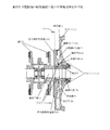
図8は、図7に示す従来の車両の駆動部の部分断面図である。
図8には、継手2と、車両用主電動機1が備える軸受装置の断面が示される。該軸受装置は、軸受カバー10、油掻揚げ円板12、軸受13、軸受押え14、軸受箱15、油溜め室10c、15a、ラビリンス10d、15c、給油室18、貯油室18aを備える。11は車両用主電動機1の回転子軸、17は車両用主電動機1の外カバーである。図8に示す軸受装置は、回転子軸11の軸受13に潤滑油を供給して潤滑する。継手2は、上記回転子軸11に取り付けられている回転体である。継手2は、軸受装置に対向する位置に設けられ、回転子軸11を中心に回転する。なお、可撓継手2以外の回転体を回転子軸11に取り付け、該回転体を該軸受装置に対向する位置に設けるようにしてもよい。
FIG. 8 is a partial cross-sectional view of the drive unit of the conventional vehicle shown in FIG.
FIG. 8 shows a cross section of the bearing device included in the joint 2 and the vehicular main motor 1. The bearing device includes a
貯油室18aは、給油室18の下部の、潤滑油が貯蔵される部分である。油掻揚げ円板12は回転子軸11に取り付けられ、その下側の一部が貯油室18aの油中に浸されている。油掻揚げ円板12が回転子軸11とともに回転すると、貯油室18aの油が掻き揚げられ、給油室18内に広がる。軸受箱15には軸受13が設けられ、回転子軸11は軸受13により回転可能に支持されている。油溜め室15aは軸受箱15に設けられ、上記軸受13を潤滑した油が溜められる。ラビリンス15cは、回転子軸11と軸受箱15の隙間を通って油が機内に漏れるのを抑制している。 The oil storage chamber 18a is a portion of the lower portion of the oil supply chamber 18 where lubricating oil is stored. The oil-raised disk 12 is attached to the rotor shaft 11, and a part of the lower side thereof is immersed in the oil in the oil storage chamber 18a. When the oil scooping disc 12 rotates with the rotor shaft 11, the oil in the oil storage chamber 18 a is swept up and spreads in the oil supply chamber 18. A bearing 13 is provided in the bearing box 15, and the rotor shaft 11 is rotatably supported by the bearing 13. The oil sump chamber 15a is provided in the bearing box 15, and the oil which lubricated the bearing 13 is stored. The labyrinth 15c prevents oil from leaking through the gap between the rotor shaft 11 and the bearing housing 15 into the machine.
軸受押え14は、軸受箱15に取り付けられ、円環形状を有する。軸受押え14は、軸受13が軸受箱15から離脱しないように軸受箱15の外側から押えている。軸受カバー10は、機外側側面に取り付けられ、中心部に上記回転子軸11が貫通する穴を有する。軸受カバー10は上記給油室18の側面を覆うように配置され、該軸受カバー10と軸受箱15の間の空間に上記給油室18が形成される。
油溜め室10cは、軸受カバー10の内周側に設けられ、油掻揚げ円板12と軸受カバー10との間の空間(後述する図10中に示す空間10b)から漏れてくる油が溜められる。該油溜め室10cは円環形状を有する。ラビリンス10dは、軸受カバー10と機外側との間に設けられ、上記油溜め室10cに溜められた油が機外側に漏れないようにシールしている。すなわち、上記ラビリンス15c、10dを用いたラビリンス構造によって、軸受装置内と軸受装置外はシールされている。
The bearing retainer 14 is attached to the bearing housing 15 and has an annular shape. The bearing retainer 14 is retained from the outside of the bearing housing 15 so that the bearing 13 is not detached from the bearing housing 15. The
The oil sump chamber 10c is provided on the inner peripheral side of the
図9は、図8中に示す軸受装置を継手側から見た正面図である。図9中に示すRは、継手2の回転半径である。 FIG. 9 is a front view of the bearing device shown in FIG. 8 viewed from the joint side. R shown in FIG. 9 is the turning radius of the joint 2.
図10は、図8を参照して説明した車両用主電動機の軸受装置の部分拡大断面図である。
図8を参照して説明した軸受装置における、軸受13への油の供給は、以下のようにして行われる。まず、貯油室18aに溜められた潤滑油が油掻揚げ円板12の回転により上部へ掻揚げられる。この掻揚げられた潤滑油が、図10中の矢印aに示すように、軸受押え14に設けられた給油穴4aを通じて軸受13内に導かれ、軸受13を潤滑して、貯油室18aに戻される。また、該軸受13内に導かれた油は、回転子軸11と軸受箱15との間の隙間を通って油溜め室15aに流れ込んで溜まる。一方、油掻揚げ円板12と軸受カバー10との間の空間10b内の油は、軸受カバー10と回転子軸11の隙間から、図10の矢印bに示すように、油溜め室10cに漏出し、油溜め室10c内に溜まる。
FIG. 10 is a partial enlarged cross-sectional view of the bearing device for the vehicle main motor described with reference to FIG. 8.
The supply of oil to the bearing 13 in the bearing device described with reference to FIG. 8 is performed as follows. First, the lubricating oil stored in the oil storage chamber 18 a is swept upward by the rotation of the oil scooping disk 12. As shown by an arrow a in FIG. 10, the scraped lubricating oil is guided into the bearing 13 through the oil supply hole 4a provided in the bearing retainer 14, lubricates the bearing 13, and returns to the oil storage chamber 18a. It is. Further, the oil guided into the bearing 13 flows into the oil sump chamber 15 a through the gap between the rotor shaft 11 and the bearing housing 15 and accumulates. On the other hand, the oil in the space 10b between the oil lifting disk 12 and the
なお、従来の具体的な車両用主電動機における油潤滑の軸受構造については、例えば特許文献2、3に記載のものが知られている。特許文献2、3に記載のものは、回転軸に取り付けられた回転板により、給油室に溜められた潤滑油を掻き揚げて軸受箱に供給するようにしたものである。上記従来の軸受装置においては、給油室や軸受箱等と機外との間をラビリンス構造によりシールし、軸受装置内の油が主電動機の機外へ漏出するのを抑制している。
しかし、図8乃至10を参照して説明した従来の車両用主電動機の軸受装置では、以下のような問題がある。
車両用主電動機使用時に、車両用主電動機の回転子軸11に取り付けられた継手2等の回転体が回転運動することにより、該回転体の回転半径内側の圧力が低下し、該回転半径の内側にある車両用主電動機の軸受装置近傍の空間の圧力が低下する。その結果、車両用主電動機の軸受装置内の潤滑油(図10中の油溜め室10cに溜まった潤滑油)が、ラビリンス10dを通して機外に吸い出されて油漏れが発生する。油が機外に多量に漏れた場合は、軸受の潤滑不良を起こし、軸受破損の原因となる。
本発明は上記従来技術の問題点を解決するためになされたものであって、その目的は、特に潤滑油の機外への漏出を抑制することができる、車両用主電動機の油漏れ抑制構造を提供することである。
However, the conventional vehicular main motor bearing device described with reference to FIGS. 8 to 10 has the following problems.
When the vehicle main motor is used, the rotary body such as the joint 2 attached to the rotor shaft 11 of the vehicle main motor rotates, so that the pressure inside the rotation radius of the rotary body decreases, and the rotation radius The pressure in the space in the vicinity of the bearing device of the vehicle main motor inside is reduced. As a result, the lubricating oil in the bearing device of the vehicular main motor (the lubricating oil collected in the oil sump chamber 10c in FIG. 10) is sucked out of the machine through the labyrinth 10d and oil leakage occurs. If a large amount of oil leaks outside the machine, it will cause poor lubrication of the bearing and cause damage to the bearing.
The present invention has been made to solve the above-described problems of the prior art, and its object is to suppress the leakage of lubricating oil to the outside of the machine, in particular, an oil leakage suppression structure for a vehicular main motor. Is to provide.
上記課題を本発明においては、次のように解決する。
回転子軸の軸受に潤滑油を供給して潤滑する軸受装置を有し、該軸受装置に対向する位置に、該回転子軸を中心に回転する回転体を有する継手が設けられた車両用主電動機における油漏れ抑制構造であって、上記軸受装置の側面を含み上記回転体と対向する面に、この回転体が含まれる空間と区画された、上記回転体の回転半径内側と外側の空間を連通させる通路が設けられる。そして、上記通路により、回転体の回転により圧力が低下した回転体の回転半径の内側にある主電動機の軸受装置近傍の空間と回転体の回転半径外側の空間をつなぎ、回転体の回転半径内外の圧力差を緩和する。
上記通路は、上記回転体の回転半径の内側から外側に連通する穴または管で構成され、
軸受装置の側面を含む面に設けられた冷却フィンの一部を利用して構成する。
In the present invention, the above problem is solved as follows.
Having a bearing device lubricated by supplying a lubricating oil to a bearing of the rotating rotor shaft, at a position opposed to the bearing device, for a vehicle coupling is provided with a rotary member which rotates about the rotor axis A structure for suppressing oil leakage in a main motor, wherein the space on the inner side and the outer side of the rotating radius of the rotating body are separated from a space including the rotating body on a surface that includes the side surface of the bearing device and faces the rotating body. There is provided a passage for communicating. The passage connects the space in the vicinity of the bearing device of the main motor inside the rotation radius of the rotating body whose pressure has been reduced by the rotation of the rotating body and the space outside the rotation radius of the rotating body, so Relieve the pressure difference.
Upper Symbol passage is constituted by a hole or a tube communicating from the inside to the outside of the rotating radius of the rotating body,
A part of the cooling fin provided on the surface including the side surface of the bearing device is used .
本発明によれば、以下の効果を得ることができる。
本発明においては、軸受装置に対向する位置に設けられた回転体の回転によって圧力が低下した該回転体の回転半径の内側にある主電動機の軸受装置近傍の空間と、該回転体の回転半径外側の空間とが、該回転体の回転半径内側と外側の空間を連通させる通路でつながれる。好ましくは、上記通路が、上記回転体の回転半径の内側から外側に連通する穴または管で構成される。
従って、本発明によれば、上記回転体の回転半径内外の圧力差が緩和され、軸受装置内の潤滑油の機外への漏出が抑制される。その結果、軸受の潤滑性能を良好に維持することができ、軸受と潤滑油の劣化低減、車両用主電動機の保守作業の低減に寄与することができる。
特に、本発明において、上記通路は、軸受装置の側面を含む面に設けられた冷却フィンの一部を利用して構成された穴または管である。従って、本発明によれば、例えば、冷却フィンの上にフタを被せることによって、上記回転体の回転半径内側と外側の空間を連通させる穴又は管を簡易に形成することが可能となる。その結果、主電動機の軸受装置内の潤滑油の機外への漏出を簡易に抑制することができる。
According to the present invention, the following effects can be obtained.
In the present invention, the space in the vicinity of the bearing device of the main motor inside the rotation radius of the rotating body, the pressure of which is reduced by the rotation of the rotating body provided at a position facing the bearing device, and the rotation radius of the rotating body The outer space is connected by a passage that connects the inner side and the outer side of the rotation radius of the rotating body. Preferably, the passage is constituted by a hole or a tube communicating from the inside to the outside of the turning radius of the rotating body.
Therefore, according to the present invention, the pressure difference inside and outside the rotation radius of the rotating body is alleviated, and leakage of the lubricating oil in the bearing device to the outside of the machine is suppressed. As a result, the lubrication performance of the bearing can be maintained satisfactorily, contributing to a reduction in deterioration of the bearing and the lubricating oil and a reduction in maintenance work of the vehicle main motor.
In particular, in the present invention, the passage is a hole or a pipe configured by using a part of a cooling fin provided on a surface including a side surface of the bearing device. Therefore, according to the present invention, for example, by covering the cooling fin with a lid, it is possible to easily form a hole or tube that communicates the space inside and outside the rotation radius of the rotating body. As a result, leakage of the lubricating oil in the bearing device of the main motor to the outside of the machine can be easily suppressed.
以下、本発明の実施の形態を図を参照して説明する。
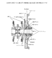
図1は、本発明の前提となる車両用主電動機の軸受装置の断面構成例を示す図である。
図1には、継手2と軸受装置の断面が示される。該軸受装置は、軸受カバー10、油掻揚げ円板12、軸受13、軸受押え14、軸受箱15、油溜め室10c、15a、ラビリンス10d、15c、給油室18、貯油室18aを備える。11は車両用主電動機の回転子軸、17は車両用主電動機の外カバー、20は圧力緩和用連通穴である。図1に示す車両用主電動機の軸受装置が備える各構成部は、図8乃至10を参照して前述した従来の車両用主電動機の軸受装置が備える同符号の構成部と同様である。また、図1に示す軸受装置を備える車両用主電動機を有する車両の駆動部の構成は、図7を参照して説明した車両の駆動部の構成と同様である。
Hereinafter, embodiments of the present invention will be described with reference to the drawings.
FIG. 1 is a diagram showing a cross-sectional configuration example of a bearing device for a vehicular main motor which is a premise of the present invention.
FIG. 1 shows a cross section of the joint 2 and the bearing device. The bearing device includes a
図1に示す軸受装置は、回転子軸11の軸受13に潤滑油を供給して潤滑する。継手2は、上記回転子軸11に取り付けられている回転体である。継手2は、軸受装置に対向する位置に設けられ、回転子軸11を中心に回転する。なお、継手2以外の回転体を回転子軸11に取り付け、該回転体を該軸受装置に対向する位置に設けるようにしてもよい。
圧力緩和用連通穴20は、軸受装置の側面を含み上記継手2等の回転体と対向する面(例えば、軸受カバー10の機外側側面)に設けられる。該圧力緩和用連通穴20は、継手2等の回転体と軸受装置の側面との間を区画して設けられる通路であって、該継手2等の回転体の回転半径内側と外側の空間を連通させる。具体的には、該圧力緩和用連通穴20は、継手2等の回転体の回転半径の内側にある主電動機の軸受装置近傍の空間(図1中のラビリンス10d近傍の空間)と該回転体の回転半径外側の空間をつなぐ。上記回転体の回転半径内側と外側の空間を連通させる通路を、該回転体の回転半径の内側から外側に連通する管で構成するようにしてもよい。
The bearing device shown in FIG. 1 lubricates the bearing 13 of the rotor shaft 11 by supplying lubricating oil. The joint 2 is a rotating body attached to the rotor shaft 11. The joint 2 is provided at a position facing the bearing device and rotates around the rotor shaft 11. A rotating body other than the joint 2 may be attached to the rotor shaft 11, and the rotating body may be provided at a position facing the bearing device.
The pressure relaxation communication hole 20 is provided on a surface (for example, the machine outer side surface of the bearing cover 10) that includes the side surface of the bearing device and faces the rotating body such as the joint 2. The communication hole 20 for pressure relaxation is a passage provided by partitioning a rotating body such as the joint 2 and the side surface of the bearing device, and a space inside and outside the rotation radius of the rotating body such as the joint 2. Communicate. Specifically, the communication hole 20 for pressure relaxation is formed in the space near the bearing device of the main motor (the space in the vicinity of the labyrinth 10d in FIG. 1) located inside the rotation radius of the rotating body such as the joint 2 and the rotating body. Connect the space outside the turning radius. You may make it comprise the channel | path which connects the space inside the rotation radius of the said rotary body, and the space outside with the pipe | tube connected from the inner side to the outer side of the rotation radius of this rotary body.
車両用主電動機使用時に、車両用主電動機の回転子軸11に取り付けられた継手2等の回転体が回転運動することにより、該回転体の回転半径内側にある主電動機の軸受装置近傍(図1中のラビリンス10d近傍)の圧力が低下する。該回転半径の内側にある主電動機の軸受装置近傍の圧力が低下すると、油溜め室10c内の潤滑油が、ラビリンス10dを通って吸い出されて、機外に漏出しようとする。しかし、上記圧力緩和用連通穴20が、継手2等の回転体の回転半径の内側にある主電動機の軸受装置近傍の空間(図1中のラビリンス10d近傍の空間)と該回転体の回転半径外側の空間とをつなぐことによって、該回転体の回転半径内外の圧力差が緩和される。その結果、軸受装置内の潤滑油(油溜め室10cに溜まった潤滑油)のラビリンス10dを通した機外への漏出が抑制される。 When the vehicle main motor is used, the rotating body such as the joint 2 attached to the rotor shaft 11 of the vehicle main motor rotates, so that the vicinity of the bearing device of the main motor inside the rotating radius of the rotating body (see FIG. 1 in the vicinity of the labyrinth 10d in 1) decreases. When the pressure in the vicinity of the bearing device of the main motor inside the turning radius decreases, the lubricating oil in the oil sump chamber 10c is sucked out through the labyrinth 10d and tends to leak out of the machine. However, the pressure relief communicating hole 20 is located inside the rotation radius of the rotating body such as the joint 2 and in the vicinity of the bearing device of the main motor (the space near the labyrinth 10d in FIG. 1) and the rotation radius of the rotating body. By connecting the outer space, the pressure difference inside and outside the rotation radius of the rotating body is alleviated. As a result, leakage of lubricating oil in the bearing device (lubricating oil accumulated in the oil sump chamber 10c) to the outside of the machine through the labyrinth 10d is suppressed.
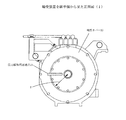
図2は、図1中に示す軸受装置を継手側から見た正面図である。
図2を参照すると、圧力緩和用連通穴20が、継手2の回転半径Rの内側にある主電動機の軸受装置近傍の空間と該継手2の回転半径外側の空間をつなぐことがわかる。
FIG. 2 is a front view of the bearing device shown in FIG. 1 viewed from the joint side.
Referring to FIG. 2, it can be seen that the pressure relief communication hole 20 connects a space near the bearing device of the main motor inside the rotation radius R of the joint 2 and a space outside the rotation radius of the joint 2.
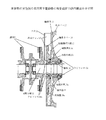
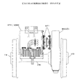
図3は、本発明の実施例の車両用主電動機の軸受装置の断面構成を示す図である。
図3には、継手2と軸受装置の断面が示される。該軸受装置は、軸受カバー10、油掻揚げ円板12、軸受13、軸受押え14、軸受箱15、油溜め室10c、15a、ラビリンス10d、15c、給油室18、貯油室18a、冷却フィン19を備える。11は車両用主電動機の回転子軸、17は車両用主電動機の外カバー、21はフタである。
図3に示す車両用主電動機の軸受装置が備える各構成部のうち、図1に示す車両用主電動機の軸受装置が備える構成部の符号と同符号のものは、図1に示す車両用主電動機が備える構成部と同様である。また、図2に示す軸受装置を備える車両用主電動機を有する車両の駆動部の構成は、図7を参照して説明した車両の駆動部の構成と同様である。
Figure 3 is a diagram showing a cross-sectional view of a bearing device for a vehicle traction motor of an embodiment of the present invention.
FIG. 3 shows a cross section of the joint 2 and the bearing device. The bearing device includes a
Of the components included in the bearing device for the vehicle main motor shown in FIG. 3, those having the same reference numerals as the components included in the bearing device for the vehicle main motor shown in FIG. This is the same as the constituent parts of the electric motor. Further, the configuration of the drive unit of the vehicle having the vehicular main motor including the bearing device shown in FIG. 2 is the same as the configuration of the drive unit of the vehicle described with reference to FIG.
図3に示す軸受装置は、回転子軸11の軸受13に潤滑油を供給して潤滑する。継手2は、上記回転子軸11に取り付けられている回転体である。継手2は、軸受装置に対向する位置に設けられ、回転子軸11を中心に回転する。なお、継手2以外の回転体を回転子軸11に取り付け、該回転体を該軸受装置に対向する位置に設けるようにしてもよい。
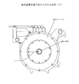
冷却フィン19は、軸受装置を冷却させる冷却器である。冷却フィン19は、軸受装置の側面を含み継手2等の回転体と対向する面(軸受カバー10の機外側側面と軸受箱15の機外側側面)に設けられる。図3中に示す軸受装置を継手側から見た正面図である図4中に示すように、軸受装置上に複数の冷却フィン19が設けられる。
フタ21は、図4に示すように、軸受装置上に設けられた複数(図4中に示す例では2個)の冷却フィン19の上に、該複数の冷却フィン19に被さるように設けられる。フタ21が冷却フィン19に被さるように設けられることにより、継手2等の回転体と軸受装置の側面との間が区画され、該継手2等の回転体の回転半径内側と外側の空間を連通させる通路が形成される。該通路は、複数の冷却フィン19の一部を利用して構成された穴または管であり、継手2等の回転体の回転半径の内側にある主電動機の軸受装置近傍の空間(図3中のラビリンス10d近傍の空間)と該回転体の回転半径外側の空間をつなぐ。
The bearing device shown in FIG. 3 lubricates the bearing 13 of the rotor shaft 11 by supplying lubricating oil. The joint 2 is a rotating body attached to the rotor shaft 11. The joint 2 is provided at a position facing the bearing device and rotates around the rotor shaft 11. A rotating body other than the joint 2 may be attached to the rotor shaft 11, and the rotating body may be provided at a position facing the bearing device.
The cooling fins 19 are coolers that cool the bearing device. The cooling fins 19 are provided on the surfaces (the outer side surface of the bearing
As shown in FIG. 4, the lid 21 is provided on a plurality of (two in the example shown in FIG. 4) cooling fins 19 provided on the bearing device so as to cover the plurality of cooling fins 19. . By providing the lid 21 so as to cover the cooling fin 19, the space between the rotating body such as the joint 2 and the side surface of the bearing device is partitioned, and the space inside and outside the rotational radius of the rotating body such as the joint 2 is communicated. A passage to be formed is formed. The passage is a hole or a pipe configured by using a part of the plurality of cooling fins 19 and is a space in the vicinity of the bearing device of the main motor inside the rotation radius of the rotating body such as the joint 2 (in FIG. 3). The space in the vicinity of the labyrinth 10d) is connected to the space outside the rotational radius of the rotating body.
車両用主電動機使用時に、車両用主電動機の回転子軸11に取り付けられた継手2等の回転体が回転運動することにより、該回転体の回転半径の内側にある主電動機の軸受装置近傍(ラビリンス10d近傍)の圧力が低下する。該回転体の回転半径の内側にある主電動機の軸受装置近傍(ラビリンス10d近傍)の圧力が低下すると、油溜め室10c内の潤滑油が、ラビリンス10dを通って吸い出されて、機外に漏出しようとする。しかし、上複数の冷却フィン19の一部を利用して構成された穴または管が、継手2等の回転体の回転半径の内側にある主電動機の軸受装置近傍の空間(ラビリンス10d近傍の空間)と該回転体の回転半径外側の空間とをつなぐことによって、該回転体の回転半径内外の圧力差が緩和される。その結果、軸受装置内の潤滑油(油溜め室10cに溜まった潤滑油)のラビリンス10dを通した機外への漏出が防止される。 When the vehicle main motor is used, the rotating body such as the joint 2 attached to the rotor shaft 11 of the vehicle main motor rotates, so that the vicinity of the bearing device of the main motor inside the rotation radius of the rotating body ( The pressure in the vicinity of the labyrinth 10d) decreases. When the pressure in the vicinity of the main motor bearing device (in the vicinity of the labyrinth 10d) inside the radius of rotation of the rotating body is reduced, the lubricating oil in the oil sump chamber 10c is sucked out through the labyrinth 10d to the outside of the machine. Try to leak. However, a hole or a tube configured by using a part of the plurality of upper cooling fins 19 is a space in the vicinity of the bearing device of the main motor (a space in the vicinity of the labyrinth 10d) inside the rotation radius of the rotating body such as the joint 2. ) And a space outside the rotation radius of the rotating body, the pressure difference inside and outside the rotation radius of the rotating body is alleviated. As a result, leakage of lubricating oil in the bearing device (lubricating oil accumulated in the oil sump chamber 10c) through the labyrinth 10d is prevented.
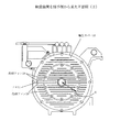
図5は、車両用主電動機の軸受装置の他の構成例を示す断面図である。
図5には、継手2と軸受装置の断面が示される。該軸受装置は、軸受カバー10、油掻揚げ円板12、軸受13、軸受押え14、軸受箱15、油溜め室10c、15a、ラビリンス10d、15c、給油室18、貯油室18aを備える。11は車両用主電動機の回転子軸、17は電動機の外カバー、20は圧力緩和用連通穴である。
図5に示す車両用主電動機の軸受装置が備える各構成部は、図1に示す車両用主電動機の軸受装置が備える同符号の構成部と同様である。また、図5に示す軸受装置を備える車両用主電動機を有する車両の駆動部の構成は、図7を参照して説明した車両の駆動部の構成と同様である。
Figure 5 is a sectional view showing another configuration example of the bearing device of the car dual traction motor.
FIG. 5 shows a cross section of the joint 2 and the bearing device. The bearing device includes a
The components included in the bearing device for the vehicle main motor shown in FIG. 5 are the same as the components having the same reference numerals provided in the bearing device for the vehicle main motor shown in FIG. Moreover, the structure of the drive part of the vehicle which has the main motor for vehicles provided with the bearing apparatus shown in FIG. 5 is the same as that of the drive part of the vehicle demonstrated with reference to FIG.
この構成例では、図5及び図5中に示す軸受装置を継手側から見た正面図である図6に示すように、軸受装置の側面を含み継手2等の回転体と対向する面(例えば、軸受カバー10の機外側側面)に、複数の圧力緩和用連通穴20を設ける。車両用主電動機使用時に、車両用主電動機の回転子軸11に取り付けられた継手2等の回転体が回転運動することにより、該回転体の回転半径内側にある主電動機の軸受装置近傍(ラビリンス10d近傍)の圧力が低下する。該回転体の回転半径の内側にある主電動機の軸受装置近傍の圧力が低下すると、油溜め室10c内の潤滑油が、ラビリンス10dを通って吸い出されて、機外に漏出しようとする。しかし、上記軸受装置の側面を含み継手2等の回転体と対向する面に設けられた各々の圧力緩和用連通穴20が、継手2等の回転体の回転半径の内側にある主電動機の軸受装置近傍の空間(ラビリンス10d近傍の空間)と該回転体の回転半径外側の空間とをつなぐことによって、該回転体の回転半径内外の圧力差が緩和される。その結果、軸受装置内の潤滑油(油溜め室10cに溜まった潤滑油)のラビリンス10dを通した機外への漏出が抑制される。
In this configuration example , as shown in FIG. 6 which is a front view of the bearing device shown in FIG. 5 and FIG. 5 as viewed from the joint side, a surface (for example, a joint 2 or the like that faces the rotating body including the side surface of the bearing device) A plurality of pressure relief communication holes 20 are provided on the outer side surface of the bearing
複数の圧力緩和用連通穴20が設けられた本構成例の車両用主電動機の軸受装置によれば、図5に示す継手1と軸受カバー10との間の隙間Sの大きさが小さく、軸受装置の側面を含み継手2等の回転体と対向する面(例えば、軸受カバー10の機外側側面)に十分な大きさの圧力緩和用連通穴20を設けることができない場合であっても、該複数の圧力緩和用連通穴20が、継手2等の回転体の回転半径の内側にある主電動機の軸受装置近傍の空間と該回転体の回転半径外側の空間とをつなぎ、該回転体の回転半径内外の圧力差を十分に緩和する。その結果、軸受装置内の潤滑油機外への漏出を効果的に抑制することが可能となる。 According to the bearing device for a vehicle main motor of this configuration example provided with a plurality of pressure relief communication holes 20, the size of the gap S between the joint 1 and the bearing cover 10 shown in FIG. Even when the pressure relief communication hole 20 having a sufficient size cannot be provided on the surface including the side surface of the apparatus and facing the rotating body such as the joint 2 (for example, the outer surface of the bearing cover 10), A plurality of pressure relief communication holes 20 connect the space in the vicinity of the bearing device of the main motor inside the rotation radius of the rotating body such as the joint 2 and the space outside the rotation radius of the rotating body, and rotate the rotating body. The pressure difference inside and outside the radius is sufficiently relaxed. As a result, it is possible to effectively suppress leakage outside the lubricating oil machine in the bearing device.
1 車両用主電動機
2 継手
3 駆動装置
4 車輪
5 車軸
10 軸受カバー
10b 空間
10c、15a 油溜め室
10d、15c ラビリンス
11 回転子軸
12 油掻揚げ円板
13 軸受
14 軸受押え
15 軸受箱
17 外カバー
18 給油室
18a 貯油室
19 冷却フィン
20 圧力緩和用連通穴
21 フタ
DESCRIPTION OF SYMBOLS 1 Vehicle main motor 2 Joint 3 Drive device 4 Wheel 5
Claims (1)
上記軸受装置の側面を含み上記回転体と対向する面に、上記回転体との間を区画して、上記回転体の回転半径内側と外側の空間を連通させる通路が設けられ、
上記通路は、上記軸受装置の側面を含み上記回転体と対向する面に設けられた冷却フィンの一部にフタを被せて形成した通路であって、
上記通路により、上記回転体の回転により圧力が低下した上記回転体の回転半径の内側にある主電動機の上記軸受装置近傍の空間と上記回転体の回転半径外側の空間をつなぎ、上記回転体の回転半径内外の圧力差を緩和する
ことを特徴とする車両用主電動機の油漏れ抑制構造。 By supplying lubricating oil to the bearing of the rotor shaft has a bearing device for lubrication, at a position opposed to said bearing device, mounted on the rotor shaft, having a rotating body that rotates about the rotor axis An oil leakage suppression structure in a vehicular main motor provided with a joint ,
The side the rotor and the opposing surfaces comprises the bearing device, and partition between said rotating body, the passage for communicating the turning radius inner and outer space of the rotary body is provided,
The passage is a passage formed by covering a part of a cooling fin provided on a surface including the side surface of the bearing device and facing the rotating body,
By the passage, connect the rotation radius space outside the space and the rotating member of the bearing device near the main motor on the inside of the rotating radius of the rotating body in which the pressure was lowered by the rotation of the rotary member, the rotary member A structure for suppressing oil leakage of a vehicular main motor characterized by relieving a pressure difference between the inside and outside of a turning radius.
Priority Applications (1)
| Application Number | Priority Date | Filing Date | Title |
|---|---|---|---|
| JP2007206288A JP5041908B2 (en) | 2007-08-08 | 2007-08-08 | Oil leakage suppression structure for vehicle main motors |
Applications Claiming Priority (1)
| Application Number | Priority Date | Filing Date | Title |
|---|---|---|---|
| JP2007206288A JP5041908B2 (en) | 2007-08-08 | 2007-08-08 | Oil leakage suppression structure for vehicle main motors |
Publications (2)
| Publication Number | Publication Date |
|---|---|
| JP2009044834A JP2009044834A (en) | 2009-02-26 |
| JP5041908B2 true JP5041908B2 (en) | 2012-10-03 |
Family
ID=40444974
Family Applications (1)
| Application Number | Title | Priority Date | Filing Date |
|---|---|---|---|
| JP2007206288A Expired - Fee Related JP5041908B2 (en) | 2007-08-08 | 2007-08-08 | Oil leakage suppression structure for vehicle main motors |
Country Status (1)
| Country | Link |
|---|---|
| JP (1) | JP5041908B2 (en) |
Families Citing this family (2)
| Publication number | Priority date | Publication date | Assignee | Title |
|---|---|---|---|---|
| JP2012102831A (en) * | 2010-11-12 | 2012-05-31 | Hitachi Ltd | Labyrinth seal device and turbo machine using the same |
| CN108711997B (en) * | 2018-05-17 | 2019-12-20 | 中车永济电机有限公司 | Multifunctional motor bearing sealing structure |
Family Cites Families (3)
| Publication number | Priority date | Publication date | Assignee | Title |
|---|---|---|---|---|
| JPS50133404U (en) * | 1974-04-19 | 1975-11-04 | ||
| JP2003032946A (en) * | 2001-07-18 | 2003-01-31 | Toshiba Transport Eng Inc | Oil-lubricated bearing structure for motors for vehicles |
| JP2006149042A (en) * | 2004-11-18 | 2006-06-08 | Yaskawa Electric Corp | Cooling device for rotating electric machine |
-
2007
- 2007-08-08 JP JP2007206288A patent/JP5041908B2/en not_active Expired - Fee Related
Also Published As
| Publication number | Publication date |
|---|---|
| JP2009044834A (en) | 2009-02-26 |
Similar Documents
| Publication | Publication Date | Title |
|---|---|---|
| CN101390275B (en) | Bearing device of main motor for vehicle | |
| US11434977B2 (en) | Vehicle drive device | |
| US8668612B2 (en) | Lubrication structure of differential gear unit | |
| US9303692B2 (en) | Lubrication of power transfer components | |
| JP5262804B2 (en) | Motor case structure | |
| JP6508148B2 (en) | In-wheel motor unit | |
| CN103863077B (en) | Driving vehicle bridge at least with an electric driving motors | |
| JP2010180911A (en) | Shaft lubricating device of hybrid working machine | |
| JP2012122552A (en) | Drive device of construction machine | |
| WO2015011976A1 (en) | Driving and transmitting device | |
| JP4684266B2 (en) | Bearing device for vehicle main motor | |
| JP5041908B2 (en) | Oil leakage suppression structure for vehicle main motors | |
| JP5722606B2 (en) | Lubrication structure of bearing in gear device | |
| US20150267803A1 (en) | Lubrication of power train components | |
| JP2008303781A (en) | Screw compressor | |
| CN111924461B (en) | A synchronous double eccentric shaft excitation device and thin oil lubrication method | |
| JPH08105523A (en) | Forced lubrication device for transmission | |
| WO2019100804A1 (en) | Hub drive assembly and vehicle | |
| JP5762128B2 (en) | Bearing device for vehicle main motor | |
| CN219013315U (en) | Unpowered two-way efficient lubrication system of electric drive bridge speed reducer | |
| US3805919A (en) | Sealing device for rotary machine | |
| JP4924404B2 (en) | Shaft sealing mechanism, and railway vehicle gear device including the same | |
| JP2003032946A (en) | Oil-lubricated bearing structure for motors for vehicles | |
| CN204900768U (en) | Bevel gear transmission, drive front axle and vehicle | |
| CN204061836U (en) | Be installed on the bearing lubrication structure of speed reducer on building hoist |
Legal Events
| Date | Code | Title | Description |
|---|---|---|---|
| A621 | Written request for application examination |
Free format text: JAPANESE INTERMEDIATE CODE: A621 Effective date: 20091104 |
|
| A977 | Report on retrieval |
Free format text: JAPANESE INTERMEDIATE CODE: A971007 Effective date: 20111130 |
|
| A131 | Notification of reasons for refusal |
Free format text: JAPANESE INTERMEDIATE CODE: A131 Effective date: 20111206 |
|
| A521 | Request for written amendment filed |
Free format text: JAPANESE INTERMEDIATE CODE: A523 Effective date: 20120123 |
|
| TRDD | Decision of grant or rejection written | ||
| A01 | Written decision to grant a patent or to grant a registration (utility model) |
Free format text: JAPANESE INTERMEDIATE CODE: A01 Effective date: 20120710 |
|
| A01 | Written decision to grant a patent or to grant a registration (utility model) |
Free format text: JAPANESE INTERMEDIATE CODE: A01 |
|
| A61 | First payment of annual fees (during grant procedure) |
Free format text: JAPANESE INTERMEDIATE CODE: A61 Effective date: 20120710 |
|
| R150 | Certificate of patent or registration of utility model |
Ref document number: 5041908 Country of ref document: JP Free format text: JAPANESE INTERMEDIATE CODE: R150 Free format text: JAPANESE INTERMEDIATE CODE: R150 |
|
| FPAY | Renewal fee payment (event date is renewal date of database) |
Free format text: PAYMENT UNTIL: 20150720 Year of fee payment: 3 |
|
| LAPS | Cancellation because of no payment of annual fees |