JP2012102831A - Labyrinth seal device and turbo machine using the same - Google Patents
Labyrinth seal device and turbo machine using the same Download PDFInfo
- Publication number
- JP2012102831A JP2012102831A JP2010253376A JP2010253376A JP2012102831A JP 2012102831 A JP2012102831 A JP 2012102831A JP 2010253376 A JP2010253376 A JP 2010253376A JP 2010253376 A JP2010253376 A JP 2010253376A JP 2012102831 A JP2012102831 A JP 2012102831A
- Authority
- JP
- Japan
- Prior art keywords
- chamber
- rotating body
- labyrinth seal
- circumferential direction
- gap
- Prior art date
- Legal status (The legal status is an assumption and is not a legal conclusion. Google has not performed a legal analysis and makes no representation as to the accuracy of the status listed.)
- Pending
Links
Images


Classifications
-
- F—MECHANICAL ENGINEERING; LIGHTING; HEATING; WEAPONS; BLASTING
- F01—MACHINES OR ENGINES IN GENERAL; ENGINE PLANTS IN GENERAL; STEAM ENGINES
- F01D—NON-POSITIVE DISPLACEMENT MACHINES OR ENGINES, e.g. STEAM TURBINES
- F01D11/00—Preventing or minimising internal leakage of working-fluid, e.g. between stages
- F01D11/02—Preventing or minimising internal leakage of working-fluid, e.g. between stages by non-contact sealings, e.g. of labyrinth type
-
- F—MECHANICAL ENGINEERING; LIGHTING; HEATING; WEAPONS; BLASTING
- F05—INDEXING SCHEMES RELATING TO ENGINES OR PUMPS IN VARIOUS SUBCLASSES OF CLASSES F01-F04
- F05D—INDEXING SCHEME FOR ASPECTS RELATING TO NON-POSITIVE-DISPLACEMENT MACHINES OR ENGINES, GAS-TURBINES OR JET-PROPULSION PLANTS
- F05D2260/00—Function
- F05D2260/96—Preventing, counteracting or reducing vibration or noise
Abstract
Description
本発明は蒸気タービン等の高速,高圧ターボ機械に好適なラビリンスシール装置に関する。 The present invention relates to a labyrinth seal device suitable for a high-speed, high-pressure turbo machine such as a steam turbine.
蒸気タービン等のターボ機械では、回転軸を収めたケーシングから作動流体が回転軸に沿って漏れることを防止するために、回転軸とケーシングとの間にラビリンスシールが設けられることが多い。
ラビリンスシールは、一般的に、回転軸の軸方向に複数のシールフィンを有しており、これらのフィンとフィンの間に回転軸の外周に沿うように圧損用空隙が形成されている。ラビリンスシールは、この圧損用空隙により、シール内を流下する漏れ流れに圧力損失を生じさせ、この圧力損失により漏れ流れを抑制することでシール機能を発揮するようになっている。
In a turbo machine such as a steam turbine, a labyrinth seal is often provided between the rotating shaft and the casing in order to prevent the working fluid from leaking along the rotating shaft from the casing containing the rotating shaft.
The labyrinth seal generally has a plurality of seal fins in the axial direction of the rotating shaft, and a pressure loss gap is formed between these fins along the outer periphery of the rotating shaft. The labyrinth seal exerts a pressure loss in the leakage flow flowing down in the seal due to the pressure loss gap, and exerts a sealing function by suppressing the leakage flow due to the pressure loss.
こうしたラビリンスシールでは、シール内を流下する漏れ流れにより回転軸の不安定振動が発生する可能性がある。具体的には、ラビリンスシール内の漏れ流れは、回転軸の回転によるつれ回り効果により、回転軸の回転と同方向の回転方向流れを伴う。この回転方向流れは、振動変位した回転軸に対して回転方向上流側に高圧部を形成し非対称圧力分布を発生させる。回転軸の回転速度が速いほど回転方向流れの流速が大きくなるが、前記圧力分布は回転軸の振動変位に対して直角方向の流体力を流速に応じた強さで発生させる。このため蒸気タービンなどの高圧ターボ機械では、高速回転時に回転軸の振動変位に対して直角方向に働く流体力が回転軸を回転方向に振れ回らせるように作用する。その結果、回転軸の振動安定性が低下して不安定振動が発生する可能性がある。 In such a labyrinth seal, there is a possibility that unstable vibration of the rotating shaft may occur due to a leakage flow flowing down in the seal. Specifically, the leakage flow in the labyrinth seal is accompanied by a rotational flow in the same direction as the rotation of the rotation shaft due to the twisting effect caused by the rotation of the rotation shaft. This flow in the rotational direction forms a high-pressure portion on the upstream side in the rotational direction with respect to the rotational shaft displaced by vibration and generates an asymmetric pressure distribution. As the rotational speed of the rotating shaft increases, the flow velocity of the rotational flow increases. However, the pressure distribution generates a fluid force in a direction perpendicular to the vibration displacement of the rotating shaft with a strength corresponding to the flow velocity. For this reason, in a high-pressure turbomachine such as a steam turbine, a fluid force acting in a direction perpendicular to the vibration displacement of the rotating shaft during high-speed rotation acts to swing the rotating shaft in the rotating direction. As a result, the vibration stability of the rotating shaft is lowered and unstable vibration may occur.
このようなラビリンスシールに関する回転軸の不安定振動問題は、回転軸の振動変位により発生する非対称圧力分布を抑えることで解消することができる。非対称圧力分布を解消する技術としては、例えば特許文献1及び2に開示の技術が知られている。
Such an unstable vibration problem of the rotating shaft related to the labyrinth seal can be solved by suppressing the asymmetric pressure distribution generated by the vibration displacement of the rotating shaft. As a technique for eliminating the asymmetric pressure distribution, for example, techniques disclosed in
特許文献1のラビリンスシールでは、シールフィン間に圧損用空隙であるチェンバーが形成されており、高圧のチェンバーと低圧のチェンバーとを連通する蒸気通路をシールリングに設けている。蒸気通路を用いて高圧のチェンバー内の漏れ流れの一部を低圧のチェンバーに逃すことで、漏れ流れの旋回流を抑制するとしている。
In the labyrinth seal of
特許文献2には、ハニカムシールにおける非対称圧力分布を解消する技術が開示されている。このハニカムシールでは、当該シール開口端より離れた部分に周方向へ連通する空間部を設け、圧損用空隙内圧力の周方向非対称分布を均一化して不安定振動に起因する流体力を抑制するとしている。
上述した特許文献1に開示されたラビリンスシール構造では、回転軸の軸方向に蒸気通路を設けて高圧のチェンバーと低圧のチェンバーとを連通させているため、下流側への漏れ量が増え、シール性が低下する可能性がある。
In the labyrinth seal structure disclosed in
さらに上述した特許文献2に開示されたハニカムシール構造では、圧損用空隙であるチャンバーに周方向に連通する空間を設けることにより周方向圧力分布の均一化ができる反面、ラビリンスシールでは既にチャンバーが周方向に連通している構造になっているため、この構造はラビリンスシールには適用できない。
Furthermore, in the honeycomb seal structure disclosed in
また、特許文献2に記載された従来技術では、特許文献1と同様に回転軸の軸方向にもチャンバーが連通しているため漏れ量が増え、シール性が低下する可能性があるが、この点については、上記従来技術では考慮されていない。
Further, in the conventional technique described in
そこで、本発明の目的は、シール内の非対称圧力分布の発生を抑制し、回転軸の不安定振動を抑制すると共に、シール性を確保できるラビリンスシール装置を提供することにある。 SUMMARY OF THE INVENTION An object of the present invention is to provide a labyrinth seal device that suppresses the generation of an asymmetric pressure distribution in a seal, suppresses unstable vibration of a rotating shaft, and ensures sealing performance.
上記の目的を達成するために、回転体と該回転体を内包する静止体との間に設けられ、前記静止体に固定されたシールリングと、該シールリングに前記回転体軸方向に複数設けられた前記回転体半径方向に突出するシールフィンとを有し、前記回転体軸方向に複数設けられたシールフィンの間にリング状のチャンバーを形成するラビリンスシール装置において、前記チャンバー内の漏れ流れを、前記チャンバーの外周側、かつ、前記回転軸周方向に一時的に逃す圧力緩和手段を備えたことを特徴とする。 In order to achieve the above object, a seal ring provided between a rotating body and a stationary body containing the rotating body and fixed to the stationary body, and a plurality of seal rings provided in the axial direction of the rotating body. A labyrinth seal device having a plurality of seal fins protruding in the radial direction of the rotating body, and forming a ring-shaped chamber between a plurality of seal fins provided in the axial direction of the rotating body. Is provided with pressure relaxation means for temporarily releasing the gas in the outer circumferential side of the chamber and in the circumferential direction of the rotation axis.
本発明のラビリンスシール装置によれば、チャンバー内の旋回する漏れ流れを、チャンバーの外周側、かつ、回転軸周方向に一時的に逃すことで、チャンバー内の圧力上昇部から圧力を逃がし、圧力上昇によるシール内の非対称圧力分布の発生を抑制し回転軸の不安定振動を抑制できると共に、シール性を確保できる。 According to the labyrinth seal device of the present invention, the leakage flow that swirls in the chamber is temporarily released in the outer peripheral side of the chamber and in the circumferential direction of the rotation axis, so that the pressure is released from the pressure increasing portion in the chamber, It is possible to suppress the occurrence of asymmetric pressure distribution in the seal due to the rise, to suppress the unstable vibration of the rotating shaft, and to ensure the sealing performance.
以下に、本発明の実施例を、図面を用いて説明する。 Embodiments of the present invention will be described below with reference to the drawings.
本発明の第1の実施例について図1乃至図6を用いて説明する。本実施例は、本発明を蒸気タービンに用いるラビリンスシール装置に適用した例である。 A first embodiment of the present invention will be described with reference to FIGS. In this embodiment, the present invention is applied to a labyrinth seal device used for a steam turbine.
まず、本発明が適用される蒸気タービンの要部構造について説明する。 First, the main structure of a steam turbine to which the present invention is applied will be described.
図1は、一般的な蒸気タービンの要部構造の一例を示した断面図である。 FIG. 1 is a cross-sectional view showing an example of a main structure of a general steam turbine.
図1において、2は回転軸、3はロータケーシング、4はノズルダイヤフラム内輪、5はダイヤフラムパッキン、6はチップフィン、7はノズルダイヤフラム外輪、8は動翼、9はノズル、10はシャフトパッキンを各々示す。 In FIG. 1, 2 is a rotating shaft, 3 is a rotor casing, 4 is a nozzle diaphragm inner ring, 5 is a diaphragm packing, 6 is a tip fin, 7 is a nozzle diaphragm outer ring, 8 is a moving blade, 9 is a nozzle, and 10 is a shaft packing. Each is shown.
蒸気タービンは主に動翼8と共に回転体を構成する回転軸2と、静止体であり、回転軸2を内包・保持するとともに作動流体である蒸気18の流路を形成するロータケーシング3とを備える。回転軸2には、周方向に複数枚の動翼8が固定されており、動翼8の蒸気流れ方向上流側に対向するようにノズル9が周方向に複数枚ロータケーシング3に固定されている。ノズル9は、外周側先端をロータケーシング3に固定されたノズルダイヤフラム外輪7に固定され、内周側先端をノズルダイヤフラム内輪4で固定されている。蒸気タービンでは、動翼8と上流側に対向して設置されるノズル9とで段落が形成され、段落が回転軸2の軸方向に複数段設置される。
The steam turbine mainly includes a rotating
作動流体である蒸気18は、ノズル9を通過する際に加速されて動翼8に送られ、動翼8で速度エネルギーから運動エネルギーに変換されて回転軸2が回転する。回転軸2は図示しない発電機と接続されており、電気エネルギーとして出力が取り出される。
The
回転体である回転軸2と静止体であるロータケーシング3との間には、回転軸2の回転を妨げないように間隙が設けられている。そして、この間隙から蒸気18の一部が漏れ流れとなって流出するが、この漏れ出た蒸気は、回転軸2の回転運動に有効に活用されないため、蒸気タービン効率低下の一因となる。
A gap is provided between the rotating
そこで、回転体である回転軸2と静止体であるロータケーシング3との間隙部には、蒸気が流出するのを防ぐため、ラビリンスシール等のシール装置が設けられている。
Therefore, a sealing device such as a labyrinth seal is provided in a gap between the rotating
例えば、ノズル9の内周側に設けられたノズルダイヤフラム内輪4と回転軸2との間隙からの蒸気の漏洩を防ぐダイヤフラムパッキン5、動翼8とロータケーシング3との間隙からの蒸気の漏洩を防ぐチップフィン6、回転軸2とロータケーシング3との間隙からの蒸気の漏洩を防ぐシャフトパッキン10にラビリンスシールが使用されている。
For example, the leakage of steam from the gap between the nozzle diaphragm
ラビリンスシールは、回転体または静止体の少なくともいずれか一方に、回転軸径方向に突出する複数のシールフィン11を有しており、これらのシールフィン間に回転軸2の外周に沿うように圧損用空隙(チャンバー12)が形成されている。ラビリンスシールは、この圧損用空隙により、シール内を流下する漏れ流れに圧力損失を生じさせ、この圧力損失により漏れ流れを抑制することでシール機能を発揮する。
The labyrinth seal has a plurality of
しかしながら、従来のラビリンスシールでは以下のような課題がある。 However, the conventional labyrinth seal has the following problems.
図5は従来のラビリンスシールのチャンバー内の圧力分布を示す模式図である。 FIG. 5 is a schematic view showing a pressure distribution in a chamber of a conventional labyrinth seal.
一般的に蒸気タービン等の軸流タービンでは、回転軸2が回転することによるつれ回り効果により、漏れ流れも回転軸2の回転方向Rに旋回して、回転方向流れRSが生じる。回転軸2が一方向に偏心(振動変位)すると、チャンバー12が偏心方向で狭まる。回転方向流れRSは回転軸2の偏心方向の上流側で流れがせき止められ、高圧部を発生させる。反対に回転軸2の偏心方向の下流側では回転方向流れRSにより流体が逃げるため低圧となる。この非対称圧力分布Pによって流体力が発生し、回転軸2が回転方向Rに押される。これにより、回転軸2が振れ回り不安定振動を起こす。
Generally, in an axial flow turbine such as a steam turbine, the leakage flow also swirls in the rotation direction R of the
以上のような従来のラビリンスシールの課題を踏まえて、本実施例のラビリンスシールについて次に説明する。 Based on the problems of the conventional labyrinth seal as described above, the labyrinth seal of the present embodiment will be described next.
本実施例は、本発明を蒸気タービンに用いるラビリンスシール装置に適用した例のうちダイヤフラムパッキン5に使用されるラビリンスシール装置に適用した例である。 The present embodiment is an example in which the present invention is applied to a labyrinth seal device used for the diaphragm packing 5 among examples applied to a labyrinth seal device used for a steam turbine.
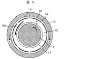
図2は、第1の実施例に係るラビリンスシール1の軸方向断面図、図3は、第1の実施例に係るラビリンスシール1の軸直角断面図、図4は、図3に示した第1の実施例に係るラビリンスシール1のX−X断面図である。
2 is an axial cross-sectional view of the
図2に示すように、ラビリンスシール1は、シールリング13とシールフィン11とを備える。シールリング13は、回転軸2の周方向に沿ってリング状に組み立てられた部材であり、ノズルダイヤフラム内輪4に固定されている。シールリング13の内周側壁面には、回転軸径方向内周側に向って突出するシールフィン11が複数枚、軸方向に設置されている。シールフィン11は、図3に示すように回転軸2の外周に沿うように周方向に向かって延伸する薄板状の部材であり、回転軸2に対して半径方向の間隙を開けて対向するように、シールリング13に固定されている。
As shown in FIG. 2, the
図2,図3に示すように、ラビリンスシール1では、シールリング13と、シールフィン11との間に、回転軸2の外周に沿って、リング状の圧損用空隙となるチャンバー12を形成している。
As shown in FIGS. 2 and 3, in the
チャンバー12は、周方向には区分けされておらず1つの空間である。このチャンバー12が圧損用空隙となり、漏れ流れがチャンバー12を通過する際に、漏れ流れに圧力損失を生じさせることで、ラビリンスシール1は漏れ流れLSを抑制してシール機能を発揮する。
The
さらに本実施例では、図2に示すように、シールリング13のチャンバー12外周位置に空隙部14を設けている。空隙部14は、図3に示すように、チャンバー12に沿って周方向に延伸した環状の空隙である。空隙部14は、軸方向に複数形成された各チャンバー12の外周にそれぞれ形成されており、各空隙部14は互いに連通しない独立した空間である。
Further, in this embodiment, as shown in FIG. 2, a
図2,図3に示すように、空隙部14は、シールリング13のチャンバー12の底部位置に相当する内周面に、周方向に延伸して形成された溝と、チャンバー12の底部位置に設置され、溝の開口部を塞ぐリング状のプレート15とで構成される。プレート15は、チャンバー12と空隙部14とを半径方向に区分けする。
As shown in FIG. 2 and FIG. 3, the
図4は、図3に示したX−X断面図である。図4において、説明のため、回転軸2は図示を省略している。図4に示したように、シールフィン11間にはそれぞれチャンバー12が形成されており、チャンバー12のそれぞれの底部にプレート15が設けられている。
4 is a cross-sectional view taken along the line XX shown in FIG. In FIG. 4, the illustration of the
各プレート15には、チャンバー12と空隙部14とを連通させる連通手段として貫通孔16がプレート15の周方向に複数設けられている。より具体的には、図4に示すように、本実施例では貫通孔16は、各プレート15毎に周方向に等間隔に8ヶ所設けられている。また、各プレート15に設けられた貫通孔16は、同位相となるように、軸方向に一直線に並んで配置されている。なお、本例は一例であり、貫通孔16の位置は8個に限定されるものではない。
Each
次に本発明の作用効果について図6を用いて説明する。図6において、破線は従来の周方向圧力分布を示す。 Next, the effect of this invention is demonstrated using FIG. In FIG. 6, the broken line shows the conventional circumferential pressure distribution.
図6に示すように、本実施例では、回転軸2が偏心してチャンバー内を旋回する漏れ流れの一部が、高圧部で堰き止められても、貫通孔16を介して、チャンバー12から空隙部14に流体が流れ込む。従来、高圧部で堰き止められていた漏れ流れを空隙部14に逃すことができるため、高圧部における圧力を逃して緩和し、圧力上昇を抑制することができる。
As shown in FIG. 6, in this embodiment, even if a part of the leakage flow in which the
空隙部14内に流入した漏れ流れは、空隙部14内を周方向低圧部側に流れる。低圧部では貫通孔16を介して空隙部14からチャンバー12に流体が流れ出ることで低圧部の圧力が増加する。この空隙部14,チャンバー12間の流体の出入りによって周方向圧力分布が均一化される。そのため、非対称圧力分布に起因する流体力を低減できる。
The leakage flow that has flowed into the
本実施例では、回転軸2が偏心してチャンバー内を旋回する漏れ流れの一部が、高圧部で堰き止められても、チャンバー12内の漏れ流れを、空隙部14を介してチャンバー12の外周側、かつ、回転軸2の周方向に一時的に逃すことができる。その結果、チャンバー12内の非対称圧力分布に起因する不安定振動をより良く抑制することができる。
In the present embodiment, even if a part of the leakage flow rotating in the chamber due to the
このとき流体の出入り口となる2ヶ所の貫通孔16の配置位置は、回転軸2の不安定振動は振れ回りであるため、どの方向に偏心する場合でも流体力を低減できるよう、周方向に均等に配置するのが望ましい。流体の出入り口となる貫通孔16の配置角度は60゜以上、180゜以下に離して設けるのが望ましい。
At this time, the positions of the two through
回転軸2の全長に対してラビリンスシール1は短いので、回転軸2の偏心方向は、各チャンバー12で同方向である。より効果的に流体力を低減するために、貫通孔16は各チャンバー12の周方向に同位相で配置するのが望ましい。
Since the
本実施例では、空隙部14は、軸方向に複数設けられた各チャンバー12の外周側にそれぞれ独立して設けられ、軸方向には連通しないため、上流側のチャンバー12から流入した漏れ流れが、空隙部14を介して下流側のチャンバー12に流出することはない。よって、漏れ量は増えずシール性の低下を招くことはない。
In the present embodiment, the
これらより、本発明のラビリンスシール1は、シール性を確保しつつ、非対称圧力分布を均一化して回転軸2の不安定振動を効果的に解消することができる。
Accordingly, the
本実施例では貫通孔16を図4の様に、円形の穴としていたが、四角形や三角形,スリットなどの形状にしてもよい。
In the present embodiment, the through-
また、貫通孔16の形状は半径方向に平行でなくても良い。チャンバー12から空隙部14に向かって末窄まりや、末広がりにしても良い。
Further, the shape of the through
また、各チャンバー12で空隙部14を配置していたが、空隙部14はすべてのチャンバー12に配置しなくてもよい。また、周方向の貫通孔16の数は2つ以上あれば良い。
Moreover, although the space |
また、本実施例は、本発明をダイヤフラムパッキン5に使用されるラビリンスシール装置に適用した例を用いて説明したが、シャフトパッキン10,チップフィン6にラビリンスシール装置を使用する場合にも同様に適用することができる。 Moreover, although the present Example demonstrated using the example which applied this invention to the labyrinth seal apparatus used for the diaphragm packing 5, when using a labyrinth seal apparatus for the shaft packing 10 and the chip fin 6, it is the same. Can be applied.
次に、本発明の第2の実施例について説明する。図7は、本発明の第2の実施例に係るラビリンスシール装置の軸方向断面図の例である。第1の実施例と同等の構成要素には同一の符号を付し、説明を省略する。 Next, a second embodiment of the present invention will be described. FIG. 7 is an example of an axial sectional view of the labyrinth seal device according to the second embodiment of the present invention. Constituent elements equivalent to those of the first embodiment are denoted by the same reference numerals, and description thereof is omitted.
前述した第1の実施例では、各チャンバー12で空隙部14の軸方向断面を四角形に形成している。一方、本実施例では、空隙部14の軸方向断面形状をチャンバー12側に向かって末窄まりな形状にし、プレート15を設けていない。空隙部14の軸方向断面形状を末窄まりな形状にすることで、空隙部14のチャンバー12との連通部(末窄まり部)は、周方向に連通するスリット状になる。このスリット17により十分にチャンバー12,空隙部14間で連通部が絞られているので、空隙部14内は回転方向流れRSの影響を受けにくい。本実施例の空隙部14は、チャンバー12側から外周方向へザグリ加工することで容易に得られる。
In the first embodiment described above, the cross section in the axial direction of the
本実施例の構造によっても、チャンバー12内の漏れ流れを、空隙部14を介してチャンバー12の外周側、かつ、回転軸2の周方向に一時的に逃すことができる。したがって、本実施例は、第1の実施例と同様にシール性を確保しつつ、非対称圧力分布を均一化して回転軸2の不安定振動を効果的に解消することができる。
Also with the structure of the present embodiment, the leakage flow in the
また、加えて、本実施例は、プレート15を設置する手間を省くことができ、加工容易である。
In addition, the present embodiment can save the trouble of installing the
本実施例では、空隙部14の軸方向断面形状を三角形にしたものとしていたが、空隙部14の軸方向断面形状がチャンバー12側に向かって末窄まりな形状であれば他の形状でも良い。
In this embodiment, the cross-sectional shape in the axial direction of the
本発明の第3の実施例について説明する。図8は本発明の第3の実施例に係るラビリンスシール1の軸直角断面図の例である。第1の実施例と同等の構成要素には同一の符号を付し、説明を省略する。
A third embodiment of the present invention will be described. FIG. 8 is an example of a cross-sectional view perpendicular to the axis of the
本実施例では、チャンバー12深さ(回転軸2外周からシールリング13内周までの距離)が円周方向に一様でなく、垂直方向で深く、水平方向で浅くなっている。このようなラビリンスシールは回転軸2の上下方向移動量が大きいターボ機械に用いられることがある。チャンバー12深さが浅い水平方向では、偏心時に高圧部の圧力上昇がより大きくなり、非対称圧力分布が大きくなる。
In this embodiment, the depth of the chamber 12 (distance from the outer periphery of the
前述した第1の実施例では、貫通孔16を周方向に等間隔で設けているのに対し、本実施例では、貫通孔16を、垂直方向に対してチャンバー12内で偏心時に圧力上昇が大きい水平方向により多く設けることにより、回転方向流れRSの局所的な圧力分布を抑えることができる。したがって、本実施例のラビリンスシール1では、圧力上昇が大きい方向でより効果的に圧力を逃がすことができ、回転方向流れRSに起因する回転軸2の不安定振動をより効果的に解消することができる。
In the first embodiment described above, the through
なお、本発明は上記した各実施例に限定されるものではなく、様々な形状例が含まれる。また、上記した各実施例は本発明を分かりやすく説明するために詳細に説明したものであり、必ずしも説明した全ての構成を備えるものに限定されるものではない。 In addition, this invention is not limited to each above-mentioned Example, Various shape examples are included. Further, each of the above-described embodiments has been described in detail for easy understanding of the present invention, and is not necessarily limited to the one having all the configurations described.
また、上記した各実施例は、蒸気タービンの例で説明したが、これに限られず、その他のターボ機械、例えば遠心圧縮機等にも適用可能である。 Moreover, although each above-mentioned Example demonstrated in the example of the steam turbine, it is not restricted to this, It can apply also to another turbomachine, for example, a centrifugal compressor etc.
1 ラビリンスシール
2 回転軸
3 ロータケーシング
4 ノズルダイヤフラム内輪
5 ダイヤフラムパッキン
6 チップフィン
7 ノズルダイヤフラム外輪
8 動翼
9 ノズル
10 シャフトパッキン
11 シールフィン
12 チャンバー
13 シールリング
14 空隙部
15 プレート
16 貫通孔
17 スリット
LS 漏れ流れ
RS 回転方向流れ
R 回転方向
θ 圧力ピーク−偏心方向間角度
P 非対称圧力分布
DESCRIPTION OF
Claims (14)
前記チャンバー内の漏れ流れを、前記チャンバーの外周側、かつ、前記回転軸の周方向に一時的に逃す圧力緩和構造を備えることを特徴とするラビリンスシール装置。 A seal ring provided between the rotating body and a stationary body containing the rotating body and fixed to the stationary body, and a plurality of the seal rings provided in the axial direction of the rotating body in the radial direction of the rotating body A labyrinth seal device having a plurality of projecting seal fins and forming a ring-shaped chamber between the plurality of seal fins provided in the axial direction of the rotating body,
A labyrinth seal device comprising a pressure relief structure for temporarily escaping a leakage flow in the chamber in an outer peripheral side of the chamber and in a circumferential direction of the rotating shaft.
前記圧力緩和構造は、前記チャンバーの外周側に設けられ、前記回転体周方向に延伸し、前記チャンバーと周方向に間隔を空けて複数箇所で連通する空隙部であることを特徴とするラビリンスシール装置。 The labyrinth seal device according to claim 1,
The pressure relief structure is a labyrinth seal provided on the outer peripheral side of the chamber, extending in the circumferential direction of the rotating body, and communicating with the chamber at a plurality of positions at intervals in the circumferential direction. apparatus.
前記空隙部は、前記チャンバー底部位置の前記シールリング内周面に設けられた溝と、前記チャンバーの底部に設けられ、前記溝の開口部を塞ぐプレートとで形成され、
前記プレートは、前記チャンバーと前記空隙部とを連通する連通手段を前記回転体周方向に沿って設けていることを特徴とするラビリンスシール装置。 The labyrinth seal device according to claim 2,
The gap is formed by a groove provided on the inner peripheral surface of the seal ring at the bottom of the chamber, and a plate provided at the bottom of the chamber and closing the opening of the groove.
The labyrinth seal device according to claim 1, wherein the plate is provided with communication means for communicating the chamber and the gap portion along the circumferential direction of the rotating body.
前記連通手段は、前記回転体周方向に沿って複数設けられた貫通孔であり、
該貫通孔は、周方向に等間隔で配置されていることを特徴とするラビリンスシール装置。 The labyrinth seal device according to claim 3,
The communication means is a plurality of through holes provided along the circumferential direction of the rotating body,
The labyrinth seal device, wherein the through holes are arranged at equal intervals in the circumferential direction.
前記チャンバーは、前記回転体軸方向に複数形成され、
前記空隙部は、前記回転体軸方向に複数設けられた前記チャンバーの外周側にそれぞれ設けられ、
前記各チャンバーの前記プレートに設けられた前記貫通孔の位置が周方向に同位相で配置されていることを特徴とするラビリンスシール装置。 The labyrinth seal device according to claim 4,
A plurality of the chambers are formed in the direction of the rotating body axis,
The voids are respectively provided on the outer peripheral side of the chamber provided in the rotating body axial direction,
The labyrinth seal device, wherein the positions of the through holes provided in the plates of the chambers are arranged in the same phase in the circumferential direction.
前記チャンバーは、前記静止体水平方向のチャンバー深さが、前記静止体垂直方向のチャンバー深さよりも浅く形成されており、
前記連通手段は、貫通孔であり、前記垂直方向よりも前記水平方向に多く設けられていることを特徴とするラビリンスシール装置。 The labyrinth seal device according to claim 3,
The chamber is formed such that the chamber depth in the horizontal direction of the stationary body is shallower than the chamber depth in the vertical direction of the stationary body,
The labyrinth seal device according to claim 1, wherein the communication means is a through-hole and is provided more in the horizontal direction than in the vertical direction.
前記圧力緩和構造は、前記チャンバーの外周側に設けられ、前記回転体周方向に延伸し、前記チャンバーと連通する空隙部であり、
該空隙部は、前記チャンバー側に向かって末窄まりとなる断面形状を有する溝を前記シールリングに設けてなり、
前記空隙部と前記チャンバーとは、前記溝の末窄まり部に、前記回転体の周方向に延伸して形成されたスリットを介して連通していることを特徴とするラビリンスシール装置。 The labyrinth seal device according to claim 1,
The pressure relaxation structure is provided on the outer peripheral side of the chamber, extends in the circumferential direction of the rotating body, and is a gap that communicates with the chamber.
The gap portion is provided with a groove in the seal ring having a cross-sectional shape that narrows toward the chamber side,
The labyrinth seal device is characterized in that the gap and the chamber communicate with a constricted portion of the groove through a slit formed by extending in a circumferential direction of the rotating body.
ロータケーシングと、該ロータケーシングに固定される静翼とを有し、前記回転体を内包する静止体と、
前記回転体と前記静止体との間に設けられ、前記静止体に固定されたシールリングと、該シールリングに前記回転体軸方向に複数設けられた、前記回転体半径方向に突出するシールフィンとを有し、前記回転体軸方向に複数設けられたシールフィンの間にリング状のチャンバーを形成するラビリンスシール装置と、を備えるターボ機械であって、
前記ラビリンスシール装置は、前記チャンバー内の漏れ流れを、前記チャンバーの外周側、かつ、前記回転軸の周方向に一時的に逃す圧力緩和構造を備えることを特徴とするターボ機械。 A rotating body having a rotating shaft and a moving blade fixed to the rotating shaft;
A stationary body having a rotor casing and a stationary blade fixed to the rotor casing, and enclosing the rotating body;
A seal ring provided between the rotating body and the stationary body and fixed to the stationary body, and a plurality of seal fins provided in the seal ring in the axial direction of the rotating body and projecting in the radial direction of the rotating body A labyrinth seal device that forms a ring-shaped chamber between a plurality of seal fins provided in the axial direction of the rotating body,
The said labyrinth seal apparatus is provided with the pressure relaxation structure which escapes the leakage flow in the said chamber temporarily in the outer peripheral side of the said chamber and the circumferential direction of the said rotating shaft, The turbomachine characterized by the above-mentioned.
前記圧力緩和構造は、前記チャンバーの外周側に、前記回転体周方向に延伸し、前記チャンバーと周方向に間隔を空けて複数箇所で連通する空隙部であることを特徴とするターボ機械。 The turbomachine according to claim 8,
The turbo machine according to claim 1, wherein the pressure relaxation structure is a gap that extends in the circumferential direction of the rotating body on the outer circumferential side of the chamber and communicates with the chamber at a plurality of positions at intervals in the circumferential direction.
前記空隙部は、前記チャンバー底部位置の前記シールリング内周面に設けられた溝と、前記チャンバーの底部に設けられ、前記溝の開口部を塞ぐプレートとで形成され、
前記プレートは、前記チャンバーと前記空隙部とを連通する連通手段を前記回転体周方向に沿って設けていることを特徴とするターボ機械。 The turbomachine according to claim 9,
The gap is formed by a groove provided on the inner peripheral surface of the seal ring at the bottom of the chamber, and a plate provided at the bottom of the chamber and closing the opening of the groove.
The turbo machine according to claim 1, wherein the plate is provided with communication means for communicating the chamber and the gap along the circumferential direction of the rotating body.
前記連通手段は、前記回転体周方向に沿って複数設けられた貫通孔であり、
該貫通孔は、周方向に等間隔で配置されていることを特徴とするターボ機械。 The turbomachine according to claim 10,
The communication means is a plurality of through holes provided along the circumferential direction of the rotating body,
The turbo machine characterized in that the through holes are arranged at equal intervals in the circumferential direction.
前記チャンバーは、前記回転体軸方向に複数形成され、
前記空隙部は、前記回転体軸方向に複数設けられた前記チャンバーの外周側にそれぞれ設けられ、
前記各チャンバーの前記プレートに設けられた前記貫通孔の位置が周方向に同位相で配置されていることを特徴とするターボ機械。 A turbomachine according to claim 11,
A plurality of the chambers are formed in the direction of the rotating body axis,
The voids are respectively provided on the outer peripheral side of the chamber provided in the rotating body axial direction,
A turbomachine characterized in that the positions of the through holes provided in the plate of each chamber are arranged in the same phase in the circumferential direction.
前記チャンバーは、前記静止体水平方向のチャンバー深さが、前記静止体垂直方向のチャンバー深さよりも浅く形成されており、
前記連通手段は、貫通孔であり、前記垂直方向よりも前記水平方向に多く設けられていることを特徴とするターボ機械。 The turbomachine according to claim 10,
The chamber is formed such that the chamber depth in the horizontal direction of the stationary body is shallower than the chamber depth in the vertical direction of the stationary body,
The turbo machine according to claim 1, wherein the communication means is a through-hole, and is provided more in the horizontal direction than in the vertical direction.
前記圧力緩和構造は、前記チャンバーの外周側に設けられ、前記回転体周方向に延伸し、前記チャンバーと連通する空隙部であり、
該空隙部は、前記チャンバー側に向かって末窄まりとなる断面形状を有する溝を前記シールリングに設けてなり、
前記空隙部と前記チャンバーとは、前記溝の末窄まり部に、前記回転体の周方向に延伸して形成されたスリットを介して連通していることを特徴とするターボ機械。 The turbomachine according to claim 8,
The pressure relaxation structure is provided on the outer peripheral side of the chamber, extends in the circumferential direction of the rotating body, and is a gap that communicates with the chamber.
The gap portion is provided with a groove in the seal ring having a cross-sectional shape that narrows toward the chamber side,
The turbo machine according to claim 1, wherein the gap and the chamber are communicated with a terminal portion of the groove through a slit formed by extending in a circumferential direction of the rotating body.
Priority Applications (3)
| Application Number | Priority Date | Filing Date | Title |
|---|---|---|---|
| JP2010253376A JP2012102831A (en) | 2010-11-12 | 2010-11-12 | Labyrinth seal device and turbo machine using the same |
| EP11188368.2A EP2453111A3 (en) | 2010-11-12 | 2011-11-09 | Labyrinth seals for turbomachinery |
| US13/292,131 US20120121411A1 (en) | 2010-11-12 | 2011-11-09 | Labyrinth Seals for Turbomachinery |
Applications Claiming Priority (1)
| Application Number | Priority Date | Filing Date | Title |
|---|---|---|---|
| JP2010253376A JP2012102831A (en) | 2010-11-12 | 2010-11-12 | Labyrinth seal device and turbo machine using the same |
Publications (1)
| Publication Number | Publication Date |
|---|---|
| JP2012102831A true JP2012102831A (en) | 2012-05-31 |
Family
ID=45002661
Family Applications (1)
| Application Number | Title | Priority Date | Filing Date |
|---|---|---|---|
| JP2010253376A Pending JP2012102831A (en) | 2010-11-12 | 2010-11-12 | Labyrinth seal device and turbo machine using the same |
Country Status (3)
| Country | Link |
|---|---|
| US (1) | US20120121411A1 (en) |
| EP (1) | EP2453111A3 (en) |
| JP (1) | JP2012102831A (en) |
Cited By (3)
| Publication number | Priority date | Publication date | Assignee | Title |
|---|---|---|---|---|
| WO2014087512A1 (en) | 2012-12-06 | 2014-06-12 | 三菱重工コンプレッサ株式会社 | Sealing device and rotating machine |
| WO2017110613A1 (en) * | 2015-12-25 | 2017-06-29 | 三菱重工コンプレッサ株式会社 | Sealing device and rotating machine |
| US10669876B2 (en) | 2016-02-29 | 2020-06-02 | Mitsubishi Hitachi Power Systems, Ltd. | Seal structure and turbomachine |
Families Citing this family (12)
| Publication number | Priority date | Publication date | Assignee | Title |
|---|---|---|---|---|
| US8740225B2 (en) * | 2009-06-03 | 2014-06-03 | Exponential Technologies, Inc. | Hydrodynamic bore seal |
| CN102966383B (en) * | 2012-11-16 | 2015-07-08 | 清华大学 | Air seal device and manufacturing method thereof |
| CN103047421A (en) * | 2013-01-18 | 2013-04-17 | 沈阳航空航天大学 | Novel high-stability three-gas wedge sealing structure |
| CN103090012A (en) * | 2013-01-18 | 2013-05-08 | 沈阳航空航天大学 | Novel high stability dislocation four gas wedge seal structure |
| CN103047418A (en) * | 2013-01-18 | 2013-04-17 | 沈阳航空航天大学 | Novel high-stability staggering three-gas wedge sealing structure |
| CN103047417A (en) * | 2013-01-18 | 2013-04-17 | 沈阳航空航天大学 | Novel high-stable oval sealing structure |
| CN103047419A (en) * | 2013-01-18 | 2013-04-17 | 沈阳航空航天大学 | Novel high-stable four air wedge sealing structure |
| KR20200108282A (en) | 2017-12-13 | 2020-09-17 | 엑스퍼넨셜 테크놀로지스 주식회사 | Rotary fluid flow device |
| JP7349248B2 (en) * | 2019-03-08 | 2023-09-22 | 三菱重工業株式会社 | Rotating machinery and seal rings |
| US11168683B2 (en) | 2019-03-14 | 2021-11-09 | Exponential Technologies, Inc. | Pressure balancing system for a fluid pump |
| US11293295B2 (en) | 2019-09-13 | 2022-04-05 | Pratt & Whitney Canada Corp. | Labyrinth seal with angled fins |
| CN114033502B (en) * | 2021-11-10 | 2023-09-12 | 北京动力机械研究所 | Low-leakage high-reliability rotor sealing structure of radial-flow turbocharging system |
Citations (16)
| Publication number | Priority date | Publication date | Assignee | Title |
|---|---|---|---|---|
| JPS54142751U (en) * | 1978-03-29 | 1979-10-03 | ||
| JPS58152974A (en) * | 1982-03-08 | 1983-09-10 | Mitsubishi Heavy Ind Ltd | Seal device of turbo-machine |
| JPS59170406A (en) * | 1983-01-24 | 1984-09-26 | ウエスチングハウス エレクトリツク コ−ポレ−シヨン | Honeycomb-shaped labyrinth seal |
| JPH04339103A (en) * | 1991-05-14 | 1992-11-26 | Mitsubishi Heavy Ind Ltd | Seal fin clearance adjusting device |
| JPH0587291U (en) * | 1992-04-27 | 1993-11-26 | 三菱重工業株式会社 | Pump spindle cooling device |
| JPH0719005A (en) * | 1993-06-30 | 1995-01-20 | Toshiba Corp | Labyrinth seal device |
| JPH08319804A (en) * | 1995-05-24 | 1996-12-03 | Toshiba Corp | Labyrinth seal device |
| JPH08338537A (en) * | 1995-06-09 | 1996-12-24 | Toshiba Corp | Labyrinth seal |
| JPH09189232A (en) * | 1996-01-08 | 1997-07-22 | Mitsubishi Heavy Ind Ltd | Lubricating oil seal device of exhaust gas turbine supercharger |
| JP2005522659A (en) * | 2002-04-19 | 2005-07-28 | エス・ディ・ウォレン・サーヴィシーズ・カンパニー | Rotary joint |
| JP2005214144A (en) * | 2004-01-30 | 2005-08-11 | Toshiba Corp | Swirl flow prevention device for fluid machine |
| JP2009044834A (en) * | 2007-08-08 | 2009-02-26 | Toyo Electric Mfg Co Ltd | Oil-spillage suppressing structure of main motor for vehicle |
| JP2009293617A (en) * | 2008-06-02 | 2009-12-17 | General Electric Co <Ge> | Fluid seal for turbo machinery |
| JP2010007611A (en) * | 2008-06-30 | 2010-01-14 | Hitachi Ltd | Turbo-machine |
| JP2010014230A (en) * | 2008-07-04 | 2010-01-21 | Ihi Corp | Labyrinth seal and rotary machine equipped therewith |
| JP2010242695A (en) * | 2009-04-09 | 2010-10-28 | Toshiba Corp | Fluid machine and seal mechanism therefor |
Family Cites Families (7)
| Publication number | Priority date | Publication date | Assignee | Title |
|---|---|---|---|---|
| US3603599A (en) * | 1970-05-06 | 1971-09-07 | Gen Motors Corp | Cooled seal |
| CA1063139A (en) * | 1976-03-09 | 1979-09-25 | Westinghouse Electric Corporation | Variable radius springback wavy seal |
| JPS58162704A (en) * | 1982-03-19 | 1983-09-27 | Toshiba Corp | Steam turbine |
| US5161942A (en) * | 1990-10-24 | 1992-11-10 | Westinghouse Electric Corp. | Moisture drainage of honeycomb seals |
| US5190440A (en) * | 1991-03-11 | 1993-03-02 | Dresser-Rand Company | Swirl control labyrinth seal |
| FR2732416B1 (en) * | 1995-03-29 | 1997-04-30 | Snecma | CONNECTION ARRANGEMENT OF TWO ANGULAR SECTORS OF TURBOMACHINE AND JOINT DESIGNED TO BE USED IN THIS ARRANGEMENT |
| EP2083200A1 (en) * | 2008-01-24 | 2009-07-29 | Siemens Aktiengesellschaft | Seal assembly |
-
2010
- 2010-11-12 JP JP2010253376A patent/JP2012102831A/en active Pending
-
2011
- 2011-11-09 EP EP11188368.2A patent/EP2453111A3/en not_active Withdrawn
- 2011-11-09 US US13/292,131 patent/US20120121411A1/en not_active Abandoned
Patent Citations (16)
| Publication number | Priority date | Publication date | Assignee | Title |
|---|---|---|---|---|
| JPS54142751U (en) * | 1978-03-29 | 1979-10-03 | ||
| JPS58152974A (en) * | 1982-03-08 | 1983-09-10 | Mitsubishi Heavy Ind Ltd | Seal device of turbo-machine |
| JPS59170406A (en) * | 1983-01-24 | 1984-09-26 | ウエスチングハウス エレクトリツク コ−ポレ−シヨン | Honeycomb-shaped labyrinth seal |
| JPH04339103A (en) * | 1991-05-14 | 1992-11-26 | Mitsubishi Heavy Ind Ltd | Seal fin clearance adjusting device |
| JPH0587291U (en) * | 1992-04-27 | 1993-11-26 | 三菱重工業株式会社 | Pump spindle cooling device |
| JPH0719005A (en) * | 1993-06-30 | 1995-01-20 | Toshiba Corp | Labyrinth seal device |
| JPH08319804A (en) * | 1995-05-24 | 1996-12-03 | Toshiba Corp | Labyrinth seal device |
| JPH08338537A (en) * | 1995-06-09 | 1996-12-24 | Toshiba Corp | Labyrinth seal |
| JPH09189232A (en) * | 1996-01-08 | 1997-07-22 | Mitsubishi Heavy Ind Ltd | Lubricating oil seal device of exhaust gas turbine supercharger |
| JP2005522659A (en) * | 2002-04-19 | 2005-07-28 | エス・ディ・ウォレン・サーヴィシーズ・カンパニー | Rotary joint |
| JP2005214144A (en) * | 2004-01-30 | 2005-08-11 | Toshiba Corp | Swirl flow prevention device for fluid machine |
| JP2009044834A (en) * | 2007-08-08 | 2009-02-26 | Toyo Electric Mfg Co Ltd | Oil-spillage suppressing structure of main motor for vehicle |
| JP2009293617A (en) * | 2008-06-02 | 2009-12-17 | General Electric Co <Ge> | Fluid seal for turbo machinery |
| JP2010007611A (en) * | 2008-06-30 | 2010-01-14 | Hitachi Ltd | Turbo-machine |
| JP2010014230A (en) * | 2008-07-04 | 2010-01-21 | Ihi Corp | Labyrinth seal and rotary machine equipped therewith |
| JP2010242695A (en) * | 2009-04-09 | 2010-10-28 | Toshiba Corp | Fluid machine and seal mechanism therefor |
Cited By (3)
| Publication number | Priority date | Publication date | Assignee | Title |
|---|---|---|---|---|
| WO2014087512A1 (en) | 2012-12-06 | 2014-06-12 | 三菱重工コンプレッサ株式会社 | Sealing device and rotating machine |
| WO2017110613A1 (en) * | 2015-12-25 | 2017-06-29 | 三菱重工コンプレッサ株式会社 | Sealing device and rotating machine |
| US10669876B2 (en) | 2016-02-29 | 2020-06-02 | Mitsubishi Hitachi Power Systems, Ltd. | Seal structure and turbomachine |
Also Published As
| Publication number | Publication date |
|---|---|
| EP2453111A2 (en) | 2012-05-16 |
| EP2453111A3 (en) | 2015-12-16 |
| US20120121411A1 (en) | 2012-05-17 |
Similar Documents
| Publication | Publication Date | Title |
|---|---|---|
| JP2012102831A (en) | Labyrinth seal device and turbo machine using the same | |
| EP3018297B1 (en) | Sealing device and turbo machine | |
| JP6344735B2 (en) | Seal structure and rotating machine | |
| JP5972374B2 (en) | Axial fluid machine | |
| JP2010159667A (en) | Axial flow turbine | |
| JP2015108301A (en) | Seal structure and rotary machine | |
| JP2014139436A (en) | Turbomachine having swirl-inhibiting seal | |
| JP2012137006A (en) | Turbine | |
| JP5643245B2 (en) | Turbo machine | |
| CN108699915B (en) | Seal structure and turbo machine | |
| JP2014141912A (en) | Rotary machine | |
| US9896952B2 (en) | Rotating machine | |
| US10794209B2 (en) | Turbine rotor blade and rotary machine | |
| US20130223998A1 (en) | Turbo Machinery | |
| JP6571257B2 (en) | Sealing device and turbomachine | |
| JP2014152696A (en) | Labyrinth seal device, and turbomachine using the same | |
| JP6204757B2 (en) | Fluid machinery | |
| JP2020020465A (en) | Seal device and turbomachine | |
| JP2014141955A (en) | Rotary machine | |
| JP6209787B2 (en) | Seal structure and rotating machine | |
| JP2013113222A (en) | Steam turbine | |
| JP2013142435A (en) | Seal device | |
| JP2017155626A (en) | Seal structure and turbomachine | |
| JP2010242695A (en) | Fluid machine and seal mechanism therefor | |
| JP2023128491A (en) | Seal device and rotary machine |
Legal Events
| Date | Code | Title | Description |
|---|---|---|---|
| RD04 | Notification of resignation of power of attorney |
Free format text: JAPANESE INTERMEDIATE CODE: A7424 Effective date: 20120521 |
|
| A621 | Written request for application examination |
Free format text: JAPANESE INTERMEDIATE CODE: A621 Effective date: 20130110 |
|
| A977 | Report on retrieval |
Free format text: JAPANESE INTERMEDIATE CODE: A971007 Effective date: 20131010 |
|
| A131 | Notification of reasons for refusal |
Free format text: JAPANESE INTERMEDIATE CODE: A131 Effective date: 20131112 |
|
| A521 | Request for written amendment filed |
Free format text: JAPANESE INTERMEDIATE CODE: A523 Effective date: 20140114 |
|
| RD02 | Notification of acceptance of power of attorney |
Free format text: JAPANESE INTERMEDIATE CODE: A7422 Effective date: 20140124 |
|
| RD04 | Notification of resignation of power of attorney |
Free format text: JAPANESE INTERMEDIATE CODE: A7424 Effective date: 20140224 |
|
| RD04 | Notification of resignation of power of attorney |
Free format text: JAPANESE INTERMEDIATE CODE: A7424 Effective date: 20140225 |
|
| RD04 | Notification of resignation of power of attorney |
Free format text: JAPANESE INTERMEDIATE CODE: A7424 Effective date: 20140227 |
|
| A02 | Decision of refusal |
Free format text: JAPANESE INTERMEDIATE CODE: A02 Effective date: 20140624 |
|
| A711 | Notification of change in applicant |
Free format text: JAPANESE INTERMEDIATE CODE: A712 Effective date: 20140829 |