JP5039672B2 - Fuel injection structure and vehicle including the same - Google Patents

Fuel injection structure and vehicle including the same Download PDF

Info

Publication number
JP5039672B2
JP5039672B2 JP2008238318A JP2008238318A JP5039672B2 JP 5039672 B2 JP5039672 B2 JP 5039672B2 JP 2008238318 A JP2008238318 A JP 2008238318A JP 2008238318 A JP2008238318 A JP 2008238318A JP 5039672 B2 JP5039672 B2 JP 5039672B2
Authority
JP
Japan
Prior art keywords
fuel
injector
guide portion
intake duct
fuel guide
Prior art date
Legal status (The legal status is an assumption and is not a legal conclusion. Google has not performed a legal analysis and makes no representation as to the accuracy of the status listed.)
Active
Application number
JP2008238318A
Other languages
Japanese (ja)
Other versions
JP2010071153A (en
Inventor
吉晴 松田
Current Assignee (The listed assignees may be inaccurate. Google has not performed a legal analysis and makes no representation or warranty as to the accuracy of the list.)
Kawasaki Motors Ltd
Original Assignee
Kawasaki Jukogyo KK
Priority date (The priority date is an assumption and is not a legal conclusion. Google has not performed a legal analysis and makes no representation as to the accuracy of the date listed.)
Filing date
Publication date
Application filed by Kawasaki Jukogyo KK filed Critical Kawasaki Jukogyo KK
Priority to JP2008238318A priority Critical patent/JP5039672B2/en
Priority to US12/559,356 priority patent/US8151754B2/en
Publication of JP2010071153A publication Critical patent/JP2010071153A/en
Application granted granted Critical
Publication of JP5039672B2 publication Critical patent/JP5039672B2/en
Active legal-status Critical Current
Anticipated expiration legal-status Critical

Links

Images

Classifications

    • YGENERAL TAGGING OF NEW TECHNOLOGICAL DEVELOPMENTS; GENERAL TAGGING OF CROSS-SECTIONAL TECHNOLOGIES SPANNING OVER SEVERAL SECTIONS OF THE IPC; TECHNICAL SUBJECTS COVERED BY FORMER USPC CROSS-REFERENCE ART COLLECTIONS [XRACs] AND DIGESTS
    • Y02TECHNOLOGIES OR APPLICATIONS FOR MITIGATION OR ADAPTATION AGAINST CLIMATE CHANGE
    • Y02TCLIMATE CHANGE MITIGATION TECHNOLOGIES RELATED TO TRANSPORTATION
    • Y02T10/00Road transport of goods or passengers
    • Y02T10/10Internal combustion engine [ICE] based vehicles
    • Y02T10/12Improving ICE efficiencies

Description

本発明は、エンジンに供給される燃料を噴射するための燃料噴射構造、及びこれを備える自動二輪車等の乗物に関する。   The present invention relates to a fuel injection structure for injecting fuel supplied to an engine and a vehicle such as a motorcycle including the same.

乗物に搭載されるエンジンにはスロットルバルブを内蔵するスロットルボディが接続され、このスロットルボディには吸気ダクト及びエアクリーナ等が順に連設されている。これら部品の各内部空間により、エンジンへの吸気通路が形成されている(例えば特許文献1参照)。   An engine mounted on a vehicle is connected to a throttle body having a throttle valve, and an intake duct, an air cleaner, and the like are sequentially connected to the throttle body. An intake passage to the engine is formed by the internal spaces of these parts (see, for example, Patent Document 1).

特許文献1に示すように、高出力型のエンジンとして、所謂ダブルインジェクタ方式を適用したものが知られている。この方式によれば、2個のインジェクタが吸気通路におけるスロットルバルブの上流側と下流側とに分かれて設けられる。上流側のインジェクタは、例えば吸気ダクトに対して上流側となるエアクリーナに設けられることがあり、主に高回転高出力時に燃料を噴射する構成となっている。
特開2006−90289号公報
As shown in Patent Document 1, a so-called double injector system is known as a high-power engine. According to this method, two injectors are provided separately on the upstream side and the downstream side of the throttle valve in the intake passage. The upstream injector may be provided, for example, in an air cleaner on the upstream side with respect to the intake duct, and is configured to inject fuel mainly at high rotation and high output.
JP 2006-90289 A

吸気通路では、エアクリーナ側からエンジン側に向けた気流が常時発生しているのではなく、ピストンの動作に従ってエンジン側からエアクリーナ側へのエアの噴き返しも生じている。高回転高出力時には、この噴き返しのため、上流側のインジェクタから噴射された燃料の全てが吸気ダクトに導入されにくくなるおそれがある。このようにしてエアクリーナボックス内に噴き返しの燃料が貯えられると、エンジン稼動時に空燃比を制御しにくくなり、出力性能や排ガス性能に影響を及ぼすおそれがある。   In the intake passage, an air flow from the air cleaner side to the engine side is not always generated, but air is blown back from the engine side to the air cleaner side according to the operation of the piston. At the time of high rotation and high output, due to this injection back, it is difficult to introduce all of the fuel injected from the upstream injector into the intake duct. Thus, if the fuel returned to the air cleaner box is stored in the air cleaner box, it becomes difficult to control the air-fuel ratio when the engine is operating, which may affect the output performance and exhaust gas performance.

そこで、本発明は、吸気ダクトの上流側に設けられたインジェクタにより噴射された燃料が吸気ダクトに導入されやすくして燃料の噴き返し量を低減し、以ってエンジンの出力性能の低下を小さくすることを目的としている。   Therefore, the present invention makes it easy to introduce fuel injected by an injector provided on the upstream side of the intake duct into the intake duct, thereby reducing the amount of fuel sprayed back, thereby reducing the decrease in engine output performance. The purpose is to do.

かかる事情に鑑み、本発明に係る燃料噴射構造は、エンジンへの吸気通路の一部を形成する吸気ダクトの上流端開口に向けて燃料を噴射するインジェクタと、前記吸気通路内に設けられて前記インジェクタの燃料噴射部を取り囲む燃料ガイド部とを備え、前記燃料ガイド部が前記吸気ダクトの上流端開口に向けて延在し、前記エアクリーナボックスが前記インジェクタを取り付けるためのインジェクタ取付部を有し、前記燃料ガイド部は、前記エアクリーナボックスの前記インジェクタ取付部から一体的に突出して前記吸気ダクトの前記上流側開口に向けて延在し、前記インジェクタは、前記インジェクタ取付部に前記エアクリーナボックスの外から取り付けられ、前記インジェクタに燃料を分配するデリバリパイプが前記エアクリーナボックス外に配置されていることを特徴としている。 In view of such circumstances, a fuel injection structure according to the present invention includes an injector that injects fuel toward an upstream end opening of an intake duct that forms part of an intake passage to the engine, and the intake passage that is provided in the intake passage. A fuel guide portion surrounding a fuel injection portion of the injector, the fuel guide portion extends toward an upstream end opening of the intake duct, and the air cleaner box has an injector attachment portion for attaching the injector, The fuel guide portion integrally protrudes from the injector mounting portion of the air cleaner box and extends toward the upstream opening of the intake duct, and the injector is connected to the injector mounting portion from the outside of the air cleaner box. A delivery pipe that is attached and distributes fuel to the injector is provided in the air cleaner box. It is characterized in that it is arranged outside the scan.

このような構成とすることにより、吸気ダクトに対して上流側に設けられたインジェクタからの燃料は、吸気ダクトの上流端開口に向けて燃料ガイド部により案内される。このため、エアの噴き返しが生じても、このインジェクタから噴射された燃料の全てが吸気ダクトに導入されやすくなり、適正に燃料を使用することができ、エンジンの出力性能の低下を小さくすることができる。また、燃料ガイド部を設けるために専用の部品を省略することができ、構造を簡素化することができる。 With such a configuration, the fuel from the injector provided on the upstream side with respect to the intake duct is guided by the fuel guide portion toward the upstream end opening of the intake duct. For this reason, even if air is blown back, all of the fuel injected from this injector can be easily introduced into the intake duct, so that the fuel can be used properly, and the reduction in engine output performance is reduced. Can do. In addition, a dedicated part for providing the fuel guide portion can be omitted, and the structure can be simplified.

前記燃料ガイド部の先端部が前記吸気ダクト内に配されていてもよい。このような構成とすることにより、インジェクタから噴射された燃料を更に吸気ダクトに導入しやすくなる。前記エンジンが複数の気筒を有し、前記吸気ダクト及び前記インジェクタが気筒毎に設けられ、一部の気筒について前記燃料ガイド部の先端部が前記吸気ダクト内に配されており、残りの気筒については前記燃料ガイド部の前記先端部が前記吸気ダクトの前記上流端開口よりも上流側に位置してもよい。前記燃料ガイド部が、先端に向かうにつれて内周面が拡径すると共に肉厚が小さくなっていてもよい。 The front end portion of the fuel guide portion may be disposed in the intake duct. With such a configuration, it becomes easier to introduce the fuel injected from the injector into the intake duct. The engine has a plurality of cylinders, the intake duct and the injector are provided for each cylinder, and the tip of the fuel guide part is arranged in the intake duct for some cylinders, and the remaining cylinders The tip of the fuel guide may be located upstream of the upstream end opening of the intake duct. The fuel guide portion may have an inner circumferential surface that increases in diameter and a thickness that decreases toward the tip.

また、本発明に係る燃料噴射構造は、エンジンへの吸気通路の一部を形成する吸気ダクトの上流端開口に向けて燃料を噴射するインジェクタと、前記吸気通路内に設けられて前記インジェクタの燃料噴射部を取り囲む燃料ガイド部とを備え、前記燃料ガイド部が前記吸気ダクトの上流端開口に向けて延在し、前記燃料ガイド部が基端部を支点にして揺動可能に設けられ。このような構成とすることにより、燃料ガイド部の先端部の吸気ダクトに対する姿勢が可変となり、燃料の噴射方向を変化させることができる構造が実現される。 The fuel injection structure according to the present invention includes an injector that injects fuel toward an upstream end opening of an intake duct that forms a part of an intake passage to the engine, and a fuel provided in the intake passage and disposed in the intake passage. and a fuel guide portion surrounding the injector, extends the fuel guide portion toward the upstream end opening of the intake duct, the fuel guide portion is Ru swingable with a fulcrum proximal portion. By adopting such a configuration, a structure in which the posture of the tip portion of the fuel guide portion with respect to the intake duct is variable and the fuel injection direction can be changed is realized.

このとき、前記燃料ガイドを揺動させる揺動アクチュエータと、前記エンジンの運転状態に応じて前記揺動アクチュエータを動作させることにより前記燃料ガイド部を揺動させる揺動制御部とを備えていてもよい。このような構成とすることにより、エンジンの運転状態に応じて燃料の噴射方向を適宜変更可能となる。   At this time, a swing actuator that swings the fuel guide and a swing control unit that swings the fuel guide by operating the swing actuator according to an operating state of the engine may be provided. Good. With such a configuration, the fuel injection direction can be appropriately changed according to the operating state of the engine.

また、本発明に係る燃料噴射構造は、エンジンへの吸気通路の一部を形成する吸気ダクトの上流端開口に向けて燃料を噴射するインジェクタと、前記吸気通路内に設けられて前記インジェクタの燃料噴射部を取り囲む燃料ガイド部とを備え、前記燃料ガイド部が前記吸気ダクトの上流端開口に向けて延在し、前記燃料ガイド部が伸縮可能であ。このような構成とすることにより、燃料噴射部から燃料ガイド部の先端部までの距離が可変となり、吸気通路の流路抵抗を変化させてエンジン側へ送られるエア量を調節可能な構造が実現される。 The fuel injection structure according to the present invention includes an injector that injects fuel toward an upstream end opening of an intake duct that forms a part of an intake passage to the engine, and a fuel provided in the intake passage and disposed in the intake passage. and a fuel guide portion surrounding the injector, the fuel guide portion extends toward the upstream end opening of the intake duct, the fuel guide portion is Ru stretchable der. With this configuration, the distance from the fuel injection part to the tip of the fuel guide part can be varied, and a structure that can adjust the amount of air sent to the engine by changing the flow path resistance of the intake passage is realized. Is done.

このとき、前記燃料ガイド部を伸縮させる伸縮アクチュエータと、前記エンジンの運転状態に応じて前記伸縮アクチュエータを動作させることにより前記燃料ガイド部を伸縮させる伸縮制御部とを備えていてもよい。このような構成とすることにより、エンジンの運転状態に応じて吸気通路の流路抵抗を適宜変更可能となる。   At this time, an expansion / contraction actuator that expands / contracts the fuel guide portion and an expansion / contraction control portion that expands / contracts the fuel guide portion by operating the expansion / contraction actuator according to an operating state of the engine may be provided. With such a configuration, the flow passage resistance of the intake passage can be appropriately changed according to the operating state of the engine.

また、本発明に係る乗物は、上記の燃料噴射構造を備えていることを特徴としており、噴射された燃料の全てを利用して高燃費かつ高出力の乗物を提供することができるようになる。   In addition, a vehicle according to the present invention includes the fuel injection structure described above, and a vehicle with high fuel consumption and high output can be provided by using all of the injected fuel. .

以上説明したように、本発明によれば、吸気ダクトの上流側に設けられたインジェクタより噴射された燃料を吸気ダクトに導入しやすくして燃料の噴き返し量を低減し、以ってエンジンの出力性能の低下を小さくすることができる。   As described above, according to the present invention, the fuel injected from the injector provided on the upstream side of the intake duct can be easily introduced into the intake duct to reduce the amount of fuel sprayed back. A decrease in output performance can be reduced.

以下、本発明に係る実施の形態について添付図面を参照しながら説明する。ここでは本発明に係る乗物として自動二輪車を例示しており、本発明に係る燃料噴射構造に係る方向をこの自動二輪車のライダが見る方向を基準にして説明している。   Embodiments according to the present invention will be described below with reference to the accompanying drawings. Here, a motorcycle is illustrated as a vehicle according to the present invention, and the direction related to the fuel injection structure according to the present invention is described with reference to the direction viewed by the rider of the motorcycle.

(第1実施形態)
[自動二輪車]
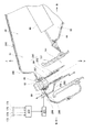
図1は本発明の第1実施形態に係る燃料噴射構造を備えた自動二輪車1の左側面図である。図1に示す自動二輪車1は、メインフレーム2の前端部にフロントフォーク3が回転可能に支持され、このフロントフォーク3の下端部に前輪4が支持されている。メインフレーム2の後方下部にはスイングアーム5が上下揺動可能に軸支され、このスイングアーム5に後輪6が支持されている。
(First embodiment)
[Motorcycle]
FIG. 1 is a left side view of a motorcycle 1 having a fuel injection structure according to a first embodiment of the present invention. In the motorcycle 1 shown in FIG. 1, a front fork 3 is rotatably supported at a front end portion of a main frame 2, and a front wheel 4 is supported at a lower end portion of the front fork 3. A swing arm 5 is pivotally supported at the rear lower part of the main frame 2 so as to be swingable up and down, and a rear wheel 6 is supported on the swing arm 5.

メインフレーム2の中央下部にはエンジン7が取り付けられている。このエンジン7の回転出力が図示しないチェーンを介して後輪6を駆動し、これにより自動二輪車1に前方への推進力が付与される。メインフレーム2の上部には、エンジン7に供給されるガソリン等の液体燃料を溜める燃料タンク8が配置されている。   An engine 7 is attached to the lower center of the main frame 2. The rotational output of the engine 7 drives the rear wheel 6 through a chain (not shown), and thereby a forward driving force is applied to the motorcycle 1. A fuel tank 8 for storing liquid fuel such as gasoline supplied to the engine 7 is disposed at the upper part of the main frame 2.

燃料タンク8の後部にはライダ用のシート9が設けられており、フロントフォーク3の上部を支持するアッパーブラケット10にはハンドル11が装着され、ハンドル11の右側にはスロットルグリップ(図示せず)が設けられている。シート9に着座したライダは、ハンドル11を回動操作して前輪4を転向させることができ、スロットルグリップ(図示せず)を捻り操作してエンジン7の回転出力を変更させることができる。   A rider seat 9 is provided at the rear of the fuel tank 8, a handle 11 is attached to the upper bracket 10 that supports the upper portion of the front fork 3, and a throttle grip (not shown) is provided on the right side of the handle 11. Is provided. The rider seated on the seat 9 can turn the handle 11 to turn the front wheel 4 and twist the throttle grip (not shown) to change the rotational output of the engine 7.

車体の前部には側方を覆う合成樹脂製のカウリング12が装着され、このカウリング12の後部はエンジン7の側部と下部とを覆っている。カウリング12の前面には空気取入口13が形成されている。燃料タンク8の下方であってエンジン7の上方にはエアクリーナボックス28が配置されている。エアクリーナボックス28は前方へ向けて開口しており、カウリング12の空気取入口13から走行風圧により流入するエアを取り込む構成になっている。   A synthetic resin cowling 12 that covers the side is attached to the front of the vehicle body, and the rear of the cowling 12 covers the side and the lower portion of the engine 7. An air intake 13 is formed on the front surface of the cowling 12. An air cleaner box 28 is disposed below the fuel tank 8 and above the engine 7. The air cleaner box 28 opens forward, and is configured to take in air that flows in from the air intake port 13 of the cowling 12 due to traveling wind pressure.

[エンジン]
図2は図1に示すエンジン7の左側断面図である。図2に示すエンジン7は4サイクル並列4気筒のレシプロエンジンであり、自動二輪車1(図1参照)に搭載された状態で4つの気筒が左右に並んで配置され、且つ出力軸であるクランク軸(図示せず)が左右に向けられる。但し、本発明に係るエンジンの気筒数や気筒のレイアウトやクランク軸の向きは、これに限られず適宜変更可能である。なお、図2は1つの気筒のみの横断面を示しているが、残りの気筒及びこれに対応する吸気通路30の横断面も図示するものと概ね同じ形状を呈している。
[engine]
FIG. 2 is a left sectional view of the engine 7 shown in FIG. The engine 7 shown in FIG. 2 is a 4-cycle parallel 4-cylinder reciprocating engine, and is mounted on the motorcycle 1 (see FIG. 1). Four cylinders are arranged side by side and a crankshaft is an output shaft. (Not shown) is directed left and right. However, the number of cylinders, the layout of the cylinders, and the direction of the crankshaft of the engine according to the present invention are not limited thereto and can be changed as appropriate. FIG. 2 shows a cross section of only one cylinder, but the remaining cylinder and the cross section of the intake passage 30 corresponding to the remaining cylinder have substantially the same shape as shown in the figure.

エンジン7は、4つのピストン(図示せず)を収容するシリンダブロック16(図1参照)に接続されるシリンダヘッド20を備えている。シリンダヘッド20には、各ピストンに個別に設けられる燃焼室21と、燃焼室21内に送られた混合気を点火するプラグ(図示せず)を収容するためのプラグ孔22とが形成されている。燃焼室21には前方に延びる排気ポート23と、後方へ延びる吸気ポート24とが連通し、混合気はこの吸気ポート24を通じて燃焼室21内に送られる。シリンダヘッド20の前部には排気マニホールド17(図1参照)が接続され、燃焼後のガスは排気ポート23及び排気マニホールドの内部を介して外部に排出される。シリンダヘッド20には、各ポート23,24を適宜タイミングで開閉する吸排気バルブ(図示せず)が設けられ、この吸排気バルブの動作により、ピストンの往復動作に応じて吸気、圧縮、膨張(燃焼)、排気がこの順で行われる。   The engine 7 includes a cylinder head 20 connected to a cylinder block 16 (see FIG. 1) that houses four pistons (not shown). The cylinder head 20 is formed with a combustion chamber 21 provided individually for each piston, and a plug hole 22 for accommodating a plug (not shown) for igniting an air-fuel mixture sent into the combustion chamber 21. Yes. An exhaust port 23 extending forward and an intake port 24 extending rearward are communicated with the combustion chamber 21, and the air-fuel mixture is sent into the combustion chamber 21 through the intake port 24. An exhaust manifold 17 (see FIG. 1) is connected to the front portion of the cylinder head 20, and the gas after combustion is discharged to the outside through the exhaust port 23 and the inside of the exhaust manifold. The cylinder head 20 is provided with an intake / exhaust valve (not shown) that opens and closes the ports 23 and 24 at appropriate timings. By the operation of the intake / exhaust valve, intake, compression, and expansion ( Combustion) and exhaust are performed in this order.

[吸気系]
シリンダヘッド20の後部には吸気装置25が設けられている。この吸気装置25は、シリンダヘッド20側から順にホルダ32、スロットルボディ26、吸気ダクト27、エアクリーナ28、及び導入ダクト(図示せず)が連設された構成となっている。これら部品が連設されると、吸気ポート24及び各部品の内部空間が互いに連通してエンジン7の燃焼室21への吸気通路30が形成される。後述するようにこのエンジン7には所謂ダブルインジェクタ方式が適用され(符号81,82参照)、吸気通路30内の2箇所にて燃料が噴射されて燃焼室21内に混合気が送られる構成となっている。
[Intake system]
An intake device 25 is provided at the rear of the cylinder head 20. The intake device 25 has a configuration in which a holder 32, a throttle body 26, an intake duct 27, an air cleaner 28, and an introduction duct (not shown) are connected in order from the cylinder head 20 side. When these components are connected in series, the intake port 24 and the internal space of each component communicate with each other to form an intake passage 30 to the combustion chamber 21 of the engine 7. As will be described later, a so-called double injector system is applied to the engine 7 (see reference numerals 81 and 82), and fuel is injected at two locations in the intake passage 30 to send an air-fuel mixture into the combustion chamber 21. It has become.

スロットルボディ26は内部空間31を有している。スロットルボディ26の一端部はホルダ32を介してシリンダヘッド20に後側から接続され、スロットルボディ26の内部空間31の中心軸線がエンジン7側から後上方に延在している。   The throttle body 26 has an internal space 31. One end of the throttle body 26 is connected to the cylinder head 20 via the holder 32 from the rear side, and the central axis of the internal space 31 of the throttle body 26 extends rearward and upward from the engine 7 side.

スロットルボディ26の下流部をなす小径部33には、メインスロットルバルブ34が内蔵されている。メインスロットルバルブ34は、内部空間31の中心軸線上を左右に延びる回転可能な弁軸35と、弁軸35に固定されて内部空間31に配設された弁体36とを備えている。また、スロットルボディ26の上流部をなす大径部37にはサブスロットルバルブ38が内蔵されており、サブスロットルバルブ38もメインスロットルバルブ34と同様構成の弁軸39及び弁体40を備えている。メインスロットルバルブ34は上記スロットルグリップ(図示せず)に機械的に接続されたワイヤによって弁軸35が回転駆動されるよう構成され、サブスロットルバルブ38は電気的に検出されたスロットルグリップの捻り操作量に基づいて弁軸39が駆動制御されるよう構成されている。弁軸35,39の回転により各弁体36,40の回転位置(つまり、スロットルバルブ34,38の開度)が変化すると、スロットルボディ26の内部空間31の流路抵抗が変化して燃焼室21へ送られるエア(混合気)の量が調整され、エンジン7の出力が変更される。   A main throttle valve 34 is built in the small diameter portion 33 that forms the downstream portion of the throttle body 26. The main throttle valve 34 includes a rotatable valve shaft 35 extending left and right on the central axis of the internal space 31, and a valve body 36 fixed to the valve shaft 35 and disposed in the internal space 31. A sub-throttle valve 38 is built in a large-diameter portion 37 that forms the upstream portion of the throttle body 26, and the sub-throttle valve 38 also includes a valve shaft 39 and a valve body 40 that have the same configuration as the main throttle valve 34. . The main throttle valve 34 is configured such that the valve shaft 35 is rotationally driven by a wire mechanically connected to the throttle grip (not shown), and the sub-throttle valve 38 is an electrically detected throttle grip twisting operation. The valve shaft 39 is configured to be driven and controlled based on the amount. When the rotational positions of the valve bodies 36 and 40 (that is, the opening degree of the throttle valves 34 and 38) change due to the rotation of the valve shafts 35 and 39, the flow path resistance of the internal space 31 of the throttle body 26 changes, and the combustion chamber The amount of air (air mixture) sent to 21 is adjusted, and the output of the engine 7 is changed.

吸気ダクト27はゴム等の弾性材料や合成樹脂材等の塑性材料から形成されて内部通路41を有しており、スロットルボディ26の他端部、すなわちエンジン7と接続される側とは反対側である上流側端部に接続されている。吸気ダクト27の外周面には、エアクリーナ28を構成するエアクリーナボックス43に接続するための係合溝42が形成されている。   The intake duct 27 is formed of an elastic material such as rubber or a plastic material such as a synthetic resin material and has an internal passage 41, and is opposite to the other end of the throttle body 26, that is, the side connected to the engine 7. Is connected to the upstream end. On the outer peripheral surface of the intake duct 27, an engagement groove 42 for connection to an air cleaner box 43 constituting the air cleaner 28 is formed.

エアクリーナボックス43は、合成樹脂材の射出成形によって形成されたロアケース44及びアッパーケース45が上下に組み付けられて構成されており、エンジン7の上方を覆うように配置されている。   The air cleaner box 43 is configured by vertically assembling a lower case 44 and an upper case 45 formed by injection molding of a synthetic resin material, and is disposed so as to cover the upper side of the engine 7.

エアクリーナボックス43が構成されると、各ケース44,45の内面により囲まれたエアクリーナボックス43の内部空間46が形成される。ロアケース44の前部にはエアを取り入れるための流入口47が形成され、ロアケース44の後下部には吸気ダクト27が接続される流出口48が形成されている。この内部空間46には、エアクリーナ28を構成するフィルタエレメント49が収容されている。このフィルタエレメント49によって内部空間46は、流入口47が形成された上流側のダーティサイド50と、流出口48が形成された下流側のクリーンサイド51とに区画される。ダーティサイド50は内部空間46における前下部に配され、クリーンサイド51は内部空間46における上部及び後下部に配されている。   When the air cleaner box 43 is configured, an internal space 46 of the air cleaner box 43 surrounded by the inner surfaces of the cases 44 and 45 is formed. An inlet 47 for taking in air is formed at the front part of the lower case 44, and an outlet 48 to which the intake duct 27 is connected is formed at the lower rear part of the lower case 44. A filter element 49 that constitutes the air cleaner 28 is accommodated in the internal space 46. The filter element 49 divides the internal space 46 into an upstream dirty side 50 in which the inflow port 47 is formed and a downstream clean side 51 in which the outflow port 48 is formed. The dirty side 50 is disposed at the front lower part in the internal space 46, and the clean side 51 is disposed at the upper part and the rear lower part in the internal space 46.

ロアケース44の底壁には、流出口48の内周囲に一体成形された鉤状の係合リブ52が設けられており、この係合リブ52は吸気ダクト27の上記係合溝42内に嵌合される。係合溝42は吸気ダクト27の外周面に形成されているため、係合溝42に対して下流側部分はエアクリーナボックス43の外側(ここでは下側)に配置され、上流側部分はエアクリーナボックス43の底壁を貫通してクリーンサイド51に配置されることとなる。吸気ダクト27がゴム等の弾性材料から形成される場合、このような配置関係となるよう吸気ダクト27をエアクリーナボックス43に容易に取り付けることができる。吸気ダクト27の上流側部分は、クリーンサイド51の後部において流出口48の形成位置から後上方へと延在し、その端部がクリーンサイド51の前上部において開口している。   The bottom wall of the lower case 44 is provided with a hook-like engagement rib 52 integrally formed on the inner periphery of the outlet 48, and the engagement rib 52 is fitted in the engagement groove 42 of the intake duct 27. Combined. Since the engaging groove 42 is formed on the outer peripheral surface of the intake duct 27, the downstream portion is disposed outside (in this case, the lower side) of the air cleaner box 43 with respect to the engaging groove 42, and the upstream portion is the air cleaner box. 43 is disposed on the clean side 51 through the bottom wall of 43. When the intake duct 27 is formed of an elastic material such as rubber, the intake duct 27 can be easily attached to the air cleaner box 43 so as to have such an arrangement relationship. The upstream portion of the intake duct 27 extends rearward and upward from the position where the outflow port 48 is formed at the rear portion of the clean side 51, and an end thereof opens at the front upper portion of the clean side 51.

各気筒において吸気を行うべく吸気ポート24が開放されると、吸気ポート24が負圧になり、空気導入口13からダーティサイド50に流入したエアがフィルタエレメント49を通過する過程で濾過され、クリーンサイド51に清浄なエアが供給される。クリーンサイド51のエアは、吸気ダクト27の内部通路41に流入し、スロットルボディ26の内部空間31を大径側から小径側へ向かって通過し、吸気ポート24に流入する。この過程でエアには燃料が混合される。また、吸気ポート24の開放直後や閉鎖直前においては吸気ポート24が瞬間的に正圧となる場合もあり、この場合には噴き返し現象が生じて吸気ポート24のエアがこれと逆方向に向けて流れる。このように吸気通路30は、上流側から順に導入ダクト(図示せず)の内部通路、エアクリーナボックス43の内部空間46、吸気ダクト27の内部通路41、スロットルボディ26の内部空間31、ホルダ32の内部通路32a、及び吸気ポート24が連通することによって構成されている。   When the intake port 24 is opened to perform intake in each cylinder, the intake port 24 becomes negative pressure, and the air flowing into the dirty side 50 from the air inlet 13 is filtered in the process of passing through the filter element 49, and is clean. Clean air is supplied to the side 51. The air on the clean side 51 flows into the internal passage 41 of the intake duct 27, passes through the internal space 31 of the throttle body 26 from the large diameter side toward the small diameter side, and flows into the intake port 24. In this process, fuel is mixed with air. In addition, immediately after the intake port 24 is opened or immediately before it is closed, the intake port 24 may instantaneously become positive pressure. In this case, a rebound phenomenon occurs and the air in the intake port 24 is directed in the opposite direction. Flowing. In this way, the intake passage 30 is arranged in order from the upstream side to the internal passage of the introduction duct (not shown), the internal space 46 of the air cleaner box 43, the internal passage 41 of the intake duct 27, the internal space 31 of the throttle body 26, and the holder 32. The internal passage 32a and the intake port 24 communicate with each other.

なお、吸気ダクト27は、係合溝42が外周面に形成された周壁61を有し、周壁61の後部からは後壁62が上方に突出している。後壁62の前側には後壁62よりも背の低い半筒状の主壁63が連続して形成されている。この主壁63の内壁面と後壁62の内壁面とで形成される空間が内部通路41の主通路53となっている。主壁63の前側には主壁63よりも背の低い半筒状の副壁64が連続して形成されている。副壁64は係合溝42を有する周壁61の前部から上方に突出して設けられており、副壁64の後端部は主壁63の下後端部及び後壁62の下両端部に連続している。その副壁64の内壁面と主壁63の外壁面とで形成される空間が内部通路41の副通路54となっている。   The intake duct 27 has a peripheral wall 61 with an engagement groove 42 formed on the outer peripheral surface, and a rear wall 62 projects upward from the rear portion of the peripheral wall 61. A semi-cylindrical main wall 63 having a lower height than the rear wall 62 is continuously formed on the front side of the rear wall 62. A space formed by the inner wall surface of the main wall 63 and the inner wall surface of the rear wall 62 is the main passage 53 of the internal passage 41. On the front side of the main wall 63, a semi-cylindrical subwall 64 having a lower height than the main wall 63 is continuously formed. The sub wall 64 is provided so as to protrude upward from the front portion of the peripheral wall 61 having the engaging groove 42, and the rear end portion of the sub wall 64 is formed at the lower rear end portion of the main wall 63 and the lower end portions of the rear wall 62. It is continuous. A space formed by the inner wall surface of the sub wall 64 and the outer wall surface of the main wall 63 is a sub passage 54 of the internal passage 41.

図3は図2のIII−III線に沿って切断して示す吸気装置25の縦断面図であり、吸気装置25の構成を、多気筒エンジンに設けられている点に鑑みてさらに説明する。図3に部分的に示すように、吸気通路30は、空気導入口13(図1参照)からエアクリーナボックス43のクリーンサイド51までの区間において、4つの気筒に共通する1系統の通路を有している。   FIG. 3 is a longitudinal sectional view of the intake device 25 cut along the line III-III in FIG. 2, and the configuration of the intake device 25 will be further described in view of being provided in a multi-cylinder engine. As partially shown in FIG. 3, the intake passage 30 has one passage common to the four cylinders in a section from the air inlet 13 (see FIG. 1) to the clean side 51 of the air cleaner box 43. ing.

ロアケース44には、気筒数に対応する4つの流出口48が左右に並んで形成され、各流出口48に吸気ダクト27が接続されている。また、スロットルボディ26のうち左側のものは左側2つの吸気ダクト27の各内部通路41と連通する2つの内部空間31を有し、右側のものは右側2つの吸気ダクト27の各内部通路41と連通する2つの内部空間31を有している。   In the lower case 44, four outlets 48 corresponding to the number of cylinders are formed side by side, and an intake duct 27 is connected to each outlet 48. The left one of the throttle bodies 26 has two internal spaces 31 communicating with the internal passages 41 of the two left intake ducts 27, and the right one includes the internal passages 41 of the two right intake ducts 27. It has two internal spaces 31 that communicate with each other.

このように吸気通路30は、図3に部分的に示すように、吸気ダクト27の内部通路41から吸気ポート24(図2参照)までの区間において、各気筒に対応して互いに独立した4系統の通路を有している。これら4系統の通路は、図3の左側から順に1番気筒、2番気筒、3番気筒、4番気筒に夫々対応している。このエンジン7では、吸気、圧縮、膨張(燃焼)及び排気の各行程が、クランク軸(図示せず)が180度回転するたびに例えば1番気筒、3番気筒、4番気筒、2番気筒、1番気筒、3番気筒…の順で行われる。   In this way, as shown in FIG. 3, the intake passage 30 has four independent systems corresponding to each cylinder in the section from the internal passage 41 of the intake duct 27 to the intake port 24 (see FIG. 2). Has a passage. These four paths correspond to the first cylinder, the second cylinder, the third cylinder, and the fourth cylinder in order from the left side of FIG. In the engine 7, each stroke of intake, compression, expansion (combustion) and exhaust is performed, for example, every time a crankshaft (not shown) rotates 180 degrees, for example, first cylinder, third cylinder, fourth cylinder, second cylinder The first cylinder, the third cylinder, and so on are performed in this order.

図4は図3に示す吸気装置25の斜視断面図であり、3番気筒に対応する吸気ダクト27の断面形状と、4番気筒に対応する吸気ダクト27の外観形状の一部とを示している。図3及び図4に示すように、1番気筒と4番気筒に対応する各吸気ダクト27(以下、これを第1吸気ダクト56とも呼ぶ)は互いの形状が同じであり、2番気筒及び3番気筒に対応する各吸気ダクト27(以下、これを第2吸気ダクト57とも呼ぶ)は互いの形状が同じである。第1吸気ダクト56と第2吸気ダクト57とは互いの形状が相違している。   FIG. 4 is a perspective sectional view of the intake device 25 shown in FIG. 3, showing a sectional shape of the intake duct 27 corresponding to the third cylinder and a part of an outer shape of the intake duct 27 corresponding to the fourth cylinder. Yes. As shown in FIGS. 3 and 4, the intake ducts 27 (hereinafter also referred to as first intake ducts 56) corresponding to the first cylinder and the fourth cylinder have the same shape, and the second cylinder and Each intake duct 27 corresponding to the third cylinder (hereinafter also referred to as a second intake duct 57) has the same shape. The first intake duct 56 and the second intake duct 57 have different shapes.

第1吸気ダクト56は、第2吸気ダクト57に比べて上流端部が短く形成され、第1吸気ダクト56は、第2吸気ダクト57に比べてエアクリーナボックス43内のクリーンサイド51での突出量が小さくなっている。   The first intake duct 56 is formed with a shorter upstream end than the second intake duct 57, and the first intake duct 56 protrudes at the clean side 51 in the air cleaner box 43 compared to the second intake duct 57. Is getting smaller.

[燃料系]
図2に戻り、このエンジン7は所謂ダブルインジェクタ方式を採用しており、吸気通路30の下流部に燃料を噴射する下流側インジェクタ81と、吸気通路30の上流部に燃料を噴射する上流側インジェクタ82とを備えている。各インジェクタ81,82はECU(図示せず)により駆動制御され、例えば下流側インジェクタ81は主にエンジン7が低負荷低回転状態から高負荷高回転状態まで全般的に動作し、上流側インジェクタ82は主にエンジン7が高負荷高回転状態のときに動作する。
[Fuel system]
Returning to FIG. 2, the engine 7 adopts a so-called double injector system, and includes a downstream injector 81 that injects fuel into the downstream portion of the intake passage 30, and an upstream injector that injects fuel into the upstream portion of the intake passage 30. 82. The injectors 81 and 82 are driven and controlled by an ECU (not shown). For example, the downstream injector 81 mainly operates from the low load low rotation state to the high load high rotation state, and the upstream injector 82. Operates mainly when the engine 7 is in a high load and high rotation state.

下流側インジェクタ81は、スロットルボディ26の後部に外側から取り付けられている。下流側インジェクタ81の燃料噴射部81aは、スロットルボディ26の内部空間31においてメインスロットルバルブ34の弁体36よりも下流側に配置されている。下流側インジェクタ81は各気筒に個別に設けられ、4つの下流側インジェクタ81が左右に並んで配置されている。各下流側インジェクタ81は、その頭部を左右に延びる下流側デリバリパイプ83に接続され、この下流側デリバリパイプ83は、燃料パイプ84を介して上流側デリバリパイプ85に接続されている。この下流側デリバリパイプ83は図示しないパイプを介して燃料タンク8(図1参照)に接続されている。これにより各上流側インジェクタ82には、燃料タンク8内の燃料が下流側デリバリパイプ83、燃料パイプ84及び上流側デリバリパイプ85を介して分配供給される。下流側インジェクタ81及び上流側インジェクタ82はそれぞれ供給された燃料を適宜タイミングで吸気通路30内に噴射する。   The downstream injector 81 is attached to the rear portion of the throttle body 26 from the outside. The fuel injection portion 81 a of the downstream injector 81 is disposed downstream of the valve body 36 of the main throttle valve 34 in the internal space 31 of the throttle body 26. The downstream injectors 81 are individually provided for each cylinder, and the four downstream injectors 81 are arranged side by side on the left and right. Each of the downstream injectors 81 is connected to a downstream delivery pipe 83 that extends from the left to the right of the head, and the downstream delivery pipe 83 is connected to an upstream delivery pipe 85 via a fuel pipe 84. The downstream delivery pipe 83 is connected to the fuel tank 8 (see FIG. 1) via a pipe (not shown). As a result, the fuel in the fuel tank 8 is distributed and supplied to each upstream injector 82 via the downstream delivery pipe 83, the fuel pipe 84, and the upstream delivery pipe 85. The downstream injector 81 and the upstream injector 82 inject the supplied fuel into the intake passage 30 at an appropriate timing.

図2に示すように、上流側のインジェクタ82は、エアクリーナ28のアッパーケース45の後上部に上側から取り付けられ、その燃料噴射部86がエアクリーナボックス43の内部空間46に配設されている。図3に示すように、上流側インジェクタ82は各気筒に個別に設けられ、4つの上流側インジェクタ82が左右に並んで配置されている。各上流側インジェクタ82は、その頭部を左右に延びる上流側デリバリパイプ85に接続されている。これにより各上流側インジェクタ82には、燃料タンク12(図1参照)内の液体燃料が上流側デリバリパイプ85を介して分配供給され、上流側インジェクタ82は供給された燃料を適宜タイミングでクリーンサイド51から吸気ダクト27の主通路53の上流端開口に向けて噴射する。   As shown in FIG. 2, the upstream injector 82 is attached to the rear upper part of the upper case 45 of the air cleaner 28 from above, and the fuel injection portion 86 is disposed in the internal space 46 of the air cleaner box 43. As shown in FIG. 3, the upstream injectors 82 are individually provided for each cylinder, and the four upstream injectors 82 are arranged side by side on the left and right. Each upstream injector 82 is connected to an upstream delivery pipe 85 extending left and right at the head. Thus, the liquid fuel in the fuel tank 12 (see FIG. 1) is distributed and supplied to each upstream injector 82 via the upstream delivery pipe 85, and the upstream injector 82 cleans the supplied fuel at an appropriate timing. Injected from 51 to the upstream end opening of the main passage 53 of the intake duct 27.

図3に示すように、アッパーケース45の上壁の後部には、各上流側インジェクタ82を取り付けるための4つのインジェクタ取付部87が左右に並んで形成されている。各インジェクタ取付部87は擂鉢状に形成され、夫々円形状である大径の上側開口と小径の下側開口とを有している。また、アッパーケース45の上壁の後部の外上面には、金属板からなるステー88がボルトで固定される。このステー88には、エアクリーナボックス43の外面と面する取付面から突出する4つのボス部89が一体的に形成されており、各ボス部89はインジェクタ取付部87内に上側開口を通じて収容される。各ボス部89は貫通孔を有しており、各ボス部89の貫通孔内にはステー88の上側から上流側インジェクタ82が1つずつ収容される。上流側インジェクタ82の外形は段付き円筒状になっているため、上流側インジェクタ82は、貫通孔内に収容されるとその段差面がボス部89に当接し、貫通孔内で保持された状態となる。このように上流側インジェクタ82がステー88を介してエアクリーナボックス43に固定されると、各上流側インジェクタ82の燃料噴射部86がインジェクタ取付部87の下側開口から僅かに突出するよう配置される。また、各上流側インジェクタ82の中心軸線は、対応する吸気ダクト27の主通路53の中心軸線及びスロットルボディ26の内部空間31の中心軸線と略一致し、燃料噴射部86が吸気ダクト27の主通路53の上流端開口の中心部に対向するよう配置されている。   As shown in FIG. 3, four injector attachment portions 87 for attaching each upstream injector 82 are formed side by side on the rear portion of the upper wall of the upper case 45. Each injector mounting portion 87 is formed in a bowl shape and has a large-diameter upper opening and a small-diameter lower opening, each of which is circular. A stay 88 made of a metal plate is fixed to the outer upper surface of the rear portion of the upper wall of the upper case 45 with a bolt. The stay 88 is integrally formed with four boss portions 89 protruding from the mounting surface facing the outer surface of the air cleaner box 43, and each boss portion 89 is accommodated in the injector mounting portion 87 through the upper opening. . Each boss portion 89 has a through hole, and one upstream injector 82 is accommodated in each through hole of each boss portion 89 from the upper side of the stay 88. Since the upstream injector 82 has a stepped cylindrical shape, when the upstream injector 82 is accommodated in the through hole, the stepped surface abuts the boss portion 89 and is held in the through hole. It becomes. Thus, when the upstream injector 82 is fixed to the air cleaner box 43 via the stay 88, the fuel injection portion 86 of each upstream injector 82 is disposed so as to slightly protrude from the lower opening of the injector mounting portion 87. . Further, the central axis of each upstream injector 82 substantially coincides with the central axis of the main passage 53 of the corresponding intake duct 27 and the central axis of the internal space 31 of the throttle body 26, and the fuel injection portion 86 is the main axis of the intake duct 27. It arrange | positions so that the center part of the upstream end opening of the channel | path 53 may be opposed.

図2に示すように、アッパーケース45の内面からは、燃料ガイド部90が一体的に突出している。燃料ガイド部90は円筒状に形成され、インジェクタ取付部87の下側開口の外周縁から流出口48に向けて延在している。このため、インジェクタ取付部87の下側開口の周囲には、燃料ガイド部90の根元部分に対して径方向内方に突出するリング状リブ91が形成されることとなり、燃料噴射部86はこのリング状リブ91及び燃料ガイド部90の根元部分の内周面とによって取り囲まれた状態となる。   As shown in FIG. 2, the fuel guide portion 90 protrudes integrally from the inner surface of the upper case 45. The fuel guide portion 90 is formed in a cylindrical shape and extends from the outer peripheral edge of the lower opening of the injector attachment portion 87 toward the outlet 48. For this reason, a ring-shaped rib 91 protruding radially inward with respect to the root portion of the fuel guide portion 90 is formed around the lower opening of the injector mounting portion 87. The ring-shaped rib 91 and the inner peripheral surface of the root portion of the fuel guide portion 90 are surrounded.

燃料ガイド部90は、その円筒部分の内周面が先端に向かうに連れて僅かに拡径している。その一方、燃料ガイド部90は全体としての大型化を避けるべく、先端に向かうに連れて肉厚が小さくなり、その外径が軸方向において略一定となっている。軸線方向に見たとき、燃料ガイド部90の先端開口は、吸気ダクト27の上流端開口の輪郭線の内側領域に配され、燃料ガイド部90の先端開口と吸気ダクト27の上流端開口の輪郭線との間には略円環状のクリアランスが形成される。ここでは、燃料ガイド部90の中心軸線は、インジェクタ取付部87の中心軸線と略一致しており、上流側インジェクタ82の中心軸線や、吸気ダクト27の主通路53の中心軸線とも略一致している。但し、燃料ガイド部90とインジェクタ取付部87とは必ずしも互いの中心軸線が一致していなくてもよい。燃料ガイド部90の先端開口は、吸気ダクト27の主通路53の上流端開口の周辺に配置され、少なくとも後壁62よりも下流側(ここでは下側)に配置されている。   The diameter of the fuel guide portion 90 is slightly increased as the inner peripheral surface of the cylindrical portion moves toward the tip. On the other hand, the thickness of the fuel guide portion 90 decreases toward the tip in order to avoid an increase in size as a whole, and the outer diameter thereof is substantially constant in the axial direction. When viewed in the axial direction, the front end opening of the fuel guide portion 90 is arranged in an inner region of the contour line of the upstream end opening of the intake duct 27, and the contour of the front end opening of the fuel guide portion 90 and the upstream end opening of the intake duct 27 is arranged. A substantially annular clearance is formed between the lines. Here, the central axis of the fuel guide portion 90 substantially coincides with the central axis of the injector mounting portion 87, and substantially coincides with the central axis of the upstream injector 82 and the central axis of the main passage 53 of the intake duct 27. Yes. However, the center axis lines of the fuel guide portion 90 and the injector mounting portion 87 do not necessarily coincide with each other. The front end opening of the fuel guide portion 90 is disposed around the upstream end opening of the main passage 53 of the intake duct 27 and is disposed at least on the downstream side (lower side here) from the rear wall 62.

このような燃料ガイド部90を有していることにより、上流側インジェクタ82から噴射された燃料は、燃料ガイド部90の内部を通過し、燃料ガイド部90の先端開口を通じて吸気通路30内に送られる。燃料ガイド部90の先端開口は吸気通路27の主通路53の上流端開口の周辺に配置されているため、燃料ガイド部90から噴射した燃料のほぼ全てが吸気ダクト27の主通路53内に導入される。この結果燃焼効率が向上し、エンジンの出力性能の低下や排ガス性能の低下を抑えることができる。   By having such a fuel guide portion 90, the fuel injected from the upstream injector 82 passes through the inside of the fuel guide portion 90 and is sent into the intake passage 30 through the front end opening of the fuel guide portion 90. It is done. Since the front end opening of the fuel guide portion 90 is disposed around the upstream end opening of the main passage 53 of the intake passage 27, almost all of the fuel injected from the fuel guide portion 90 is introduced into the main passage 53 of the intake duct 27. Is done. As a result, the combustion efficiency is improved, and the deterioration of engine output performance and exhaust gas performance can be suppressed.

また、吸気通路内30でエアの噴き返しが生じている中で上流側インジェクタ82より燃料が噴射された場合においても、燃料ガイド90が設けられずにクリーンサイド51に燃料が噴射される場合と比べ、燃料がクリーンサイド51を逆流するおそれが低減されて吸気ダクト27の主通路53内に導入されやすくなる。このため、噴射された燃料がフィルタエレメント49に付着するおそれが低減され、フィルタエレメント49の性能低下を抑えることができる。   Further, even when fuel is injected from the upstream injector 82 while air is being blown back in the intake passage 30, the fuel guide 90 is not provided and the fuel is injected into the clean side 51. In comparison, the possibility that the fuel flows back through the clean side 51 is reduced, and the fuel is easily introduced into the main passage 53 of the intake duct 27. For this reason, the possibility that the injected fuel adheres to the filter element 49 is reduced, and the performance degradation of the filter element 49 can be suppressed.

なお、本出願人が行った試験において、このような燃料ガイド部90を設けると、上流側インジェクタ82から噴射された燃料が燃料ガイド部90の内部空間をトルネード状の軌跡を描いて先端開口に向けて流れる場合があることがわかっている。このように、燃料ガイド部90を設けることにより、上流側インジェクタ82から噴射された燃料が先端開口から吸気通路30内に流入する際に霧状となりやすく、その結果燃焼効率を向上させることができる。なお、燃料ガイド部90の外壁に軸方向に延びるスリットや円形その他形状の貫通孔を形成するなど、先端開口を除く部分において燃料ガイド部90の内部を吸気通路30と連通させることにより、上流側インジェクタ82から噴射された燃料が同様の複雑な軌跡を描いて燃料ガイド部90の内部を通過しうる。   In the test conducted by the present applicant, when such a fuel guide portion 90 is provided, the fuel injected from the upstream injector 82 draws a tornado-like trajectory in the inner space of the fuel guide portion 90 and opens at the tip opening. It is known that it may flow towards you. Thus, by providing the fuel guide portion 90, the fuel injected from the upstream injector 82 is likely to form a mist when flowing into the intake passage 30 from the front end opening, and as a result, the combustion efficiency can be improved. . In addition, the inside of the fuel guide portion 90 is communicated with the intake passage 30 in a portion excluding the tip opening, such as a slit extending in the axial direction or a circular or other through-hole formed in the outer wall of the fuel guide portion 90, so that the upstream side The fuel injected from the injector 82 can pass through the inside of the fuel guide portion 90 in a similar complicated locus.

また、この燃料ガイド部90はエアクリーナボックス43のアッパーケース45を成形する際に一体的に形成されるものであるため、専用の部品を省略することができ、構造が複雑化するのを防ぐことができる。   Further, since the fuel guide portion 90 is integrally formed when the upper case 45 of the air cleaner box 43 is formed, a dedicated part can be omitted, and the structure can be prevented from becoming complicated. Can do.

図3を参照すると、燃料ガイド部90は各上流側インジェクタ82に個別に設けられている。このため、複数の気筒を有するエンジンにおいて、各気筒の燃焼効率を向上させることができる。   Referring to FIG. 3, the fuel guide portion 90 is individually provided for each upstream injector 82. For this reason, in an engine having a plurality of cylinders, the combustion efficiency of each cylinder can be improved.

また、4つの燃料ガイド部90の各軸方向長さは互いに等しいのに対し、前述したように第1吸気ダクト56の突出高さは第2吸気ダクト57に比べて小さくなっている。このため、図3及び図4を参照すると、2番及び3番気筒に対応する燃料ガイド部90の先端開口は、第2吸気ダクト57の主壁63の端縁よりも下流側に位置し、燃料ガイド部90の先端部が第2吸気ダクト57の主通路53内に配されている。これに対し、1番及び4番気筒に対応する燃料ガイド部90の先端開口は、第1吸気ダクト56の主壁63の端縁よりも上流側に位置し、燃料ガイド部90の先端部が第1吸気ダクト56の主通路53内に配置されている。   In addition, the axial lengths of the four fuel guide portions 90 are equal to each other, but the protruding height of the first intake duct 56 is smaller than that of the second intake duct 57 as described above. For this reason, referring to FIGS. 3 and 4, the tip opening of the fuel guide portion 90 corresponding to the second and third cylinders is located downstream of the edge of the main wall 63 of the second intake duct 57, The distal end portion of the fuel guide portion 90 is disposed in the main passage 53 of the second intake duct 57. On the other hand, the front end opening of the fuel guide portion 90 corresponding to the first and fourth cylinders is located upstream of the edge of the main wall 63 of the first intake duct 56, and the front end portion of the fuel guide portion 90 is The first intake duct 56 is disposed in the main passage 53.

従って、2番及び3番気筒においては、第2吸気ダクト57の主通路53の流路抵抗が増えて高回転域でのエンジン出力が減ることとなるが燃料の逆流を抑制する効果を大きくすることができる。1番及び4番気筒においては、2番及び3番気筒に比べると燃料の逆流が僅かに生じやすくなるが、第1吸気ダクト56の流路抵抗が増えることがないため高回転域でのエンジン出力を高いまま維持することができる。但し、1番及び4番気筒においても、燃料ガイド部90を設けることにより燃料の逆流を抑えることができるようになっている。このように気筒間で吸気ダクト27の主通路53に上流端開口に対する燃料ガイド部90の先端部の配置を変更することにより、高回転域でのエンジン出力を高くすることと燃料の逆流を防止することとを両立可能になる。   Therefore, in the second and third cylinders, the flow resistance of the main passage 53 of the second intake duct 57 increases and the engine output in the high rotation range decreases, but the effect of suppressing the back flow of fuel is increased. be able to. In the first and fourth cylinders, the reverse flow of the fuel is slightly more likely to occur than in the second and third cylinders, but the flow resistance of the first intake duct 56 does not increase, so the engine in the high rotation region The output can be kept high. However, also in the first and fourth cylinders, the fuel backflow can be suppressed by providing the fuel guide portion 90. In this way, by changing the arrangement of the tip of the fuel guide portion 90 with respect to the upstream end opening in the main passage 53 of the intake duct 27 between the cylinders, the engine output in the high rotation range is increased and the backflow of fuel is prevented. To do both.

なお、吸気ダクト27の上流端開口と燃料ガイド部90の先端開口との相対的な位置の関係がこのようになっていればよいため、このような関係となるよう吸気ダクトの突出高さを全て同じとし、燃料ガイド部の長さを気筒に応じて異ならせてもよい。   In addition, since the relative positional relationship between the upstream end opening of the intake duct 27 and the front end opening of the fuel guide portion 90 suffices to be like this, the protrusion height of the intake duct is set so as to satisfy such a relationship. All may be the same, and the length of the fuel guide portion may be varied depending on the cylinder.

(第2実施形態)
図5は本発明の第2実施形態に係る燃料噴射構造を備えたエンジンの吸気装置の右側断面図である。以下の説明では、上記実施形態と同一の構成については同一の符号を付して詳細な説明を省略する。
(Second Embodiment)
FIG. 5 is a right sectional view of an intake device for an engine provided with a fuel injection structure according to a second embodiment of the present invention. In the following description, the same components as those in the above embodiment are denoted by the same reference numerals, and detailed description thereof is omitted.

図5に示すように、上流側インジェクタ82はステー88のボス部89により保持され、上流側インジェクタ82の中心軸線は吸気ダクト127の内部通路141の中心軸線と略一致している。なお、この吸気ダクト127の内部通路141は第1実施形態のように主通路と副通路とに分かれてはいない。   As shown in FIG. 5, the upstream injector 82 is held by the boss portion 89 of the stay 88, and the central axis of the upstream injector 82 substantially coincides with the central axis of the internal passage 141 of the intake duct 127. Note that the internal passage 141 of the intake duct 127 is not divided into a main passage and a sub-passage as in the first embodiment.

エアクリーナボックス143のアッパーケース145には、インジェクタ取付部187の下側開口を覆うようにキャップ部材191が嵌め着けられている。このキャップ部材191の下端部にはさらに、円筒状の燃料ガイド部190が嵌め着けられている。キャップ部材191はゴム等の弾性を有した材料からなり、アッパーケース145及び燃料ガイド部190に対して強固に接着されている。燃料ガイド部190はその基端部、すなわち上流側インジェクタ82の燃料噴射部86を取り囲むような燃料噴射部86との近傍位置において、このような弾性変形可能なキャップ部材191との接着されており、燃料ガイド部190はこの接着部を支点199にして、アッパーケース145に対して揺動可能に固定されている。   A cap member 191 is fitted on the upper case 145 of the air cleaner box 143 so as to cover the lower opening of the injector mounting portion 187. A cylindrical fuel guide portion 190 is further fitted to the lower end portion of the cap member 191. The cap member 191 is made of a material having elasticity such as rubber and is firmly bonded to the upper case 145 and the fuel guide portion 190. The fuel guide portion 190 is bonded to the elastically deformable cap member 191 at the base end portion thereof, that is, in the vicinity of the fuel injection portion 86 surrounding the fuel injection portion 86 of the upstream injector 82. The fuel guide portion 190 is fixed to the upper case 145 so as to be swingable with the adhesive portion as a fulcrum 199.

燃料ガイド部190の先端部には外周面にリブ192が設けられており、このリブ192にはリンク193の先端部が揺動可能に連結されている。リンク193の基端部にはロッド194が揺動可能に連結され、このロッド194はアッパーケース145の上壁を貫通してエアクリーナボックス143の外部へと引き出されている。ロッド194はある一方向に進退可能に設けられている。なお、アッパーケース145の上壁には、ロッド194の移動をガイドするとともにエアクリーナボックス143の内部空間146の気密性を確保するためにパッキン195が設けられている。   A rib 192 is provided on the outer peripheral surface of the front end portion of the fuel guide portion 190, and the front end portion of the link 193 is swingably connected to the rib 192. A rod 194 is swingably connected to the base end portion of the link 193, and this rod 194 passes through the upper wall of the upper case 145 and is drawn out of the air cleaner box 143. The rod 194 is provided to be able to advance and retreat in a certain direction. A packing 195 is provided on the upper wall of the upper case 145 to guide the movement of the rod 194 and to ensure the airtightness of the internal space 146 of the air cleaner box 143.

このロッド194の先端には、ロッド194を駆動して進退させる揺動アクチュエータ171が接続されている。この揺動アクチュエータ171は電動のモータでもよいしソレノイドにより構成されていてもよい。   A swing actuator 171 that drives the rod 194 to advance and retreat is connected to the tip of the rod 194. The swing actuator 171 may be an electric motor or a solenoid.

また、本実施形態の自動二輪車には、この揺動アクチュエータ171の動作を制御する制御装置172が設けられている。制御装置172には、エンジンの運転状態を検出するセンサ類、例えばメインスロットルバルブの開度を検出するスロットル開度センサ173や、エンジン回転数を検出する回転数センサ174や、車速を検出する車速センサ175や、エンジンの壁面温度又は冷却水温を検出する温度センサ176等、からの検出信号が入力される。制御装置172はこれら入力された検出信号に応じて揺動アクチュエータ171を制御する。揺動アクチュエータ171の動作に応じてロッド194が進退し、ロッド194の進退方向に応じてリンク193を介してロッド194と連結された燃料ガイド部190がキャップ191との接着部を支点にして揺動する。このように揺動した燃料ガイド部190の中心軸線は、上流側インジェクタ82の中心軸線及び吸気ダクト127の内部通路141の中心軸線に対して傾斜する。キャップ191との接着部は燃料ガイド部190の基端部、すなわち上流側インジェクタ82の燃料噴射部86の近傍位置に設定されていることから、燃料ガイド部190の先端開口の吸気ダクト127の上流側開口に対する姿勢が変化する。   In addition, the motorcycle of the present embodiment is provided with a control device 172 that controls the operation of the swing actuator 171. The control device 172 includes sensors for detecting the operating state of the engine, for example, a throttle opening sensor 173 for detecting the opening of the main throttle valve, a rotation speed sensor 174 for detecting the engine speed, and a vehicle speed for detecting the vehicle speed. Detection signals from the sensor 175, the temperature sensor 176 for detecting the engine wall surface temperature or the cooling water temperature, and the like are input. The control device 172 controls the swing actuator 171 according to these input detection signals. The rod 194 advances and retreats according to the operation of the swing actuator 171, and the fuel guide portion 190 connected to the rod 194 via the link 193 according to the advance and retreat direction of the rod 194 swings with the joint portion with the cap 191 as a fulcrum. Move. The central axis of the fuel guide portion 190 that has swung in this manner is inclined with respect to the central axis of the upstream injector 82 and the central axis of the internal passage 141 of the intake duct 127. Since the bonding portion with the cap 191 is set at the base end portion of the fuel guide portion 190, that is, in the vicinity of the fuel injection portion 86 of the upstream injector 82, the upstream end of the intake duct 127 at the tip opening of the fuel guide portion 190 is set. The posture with respect to the side opening changes.

このように燃料ガイド部190の先端開口の姿勢が可変となり燃料ガイド部190の中心軸線の向きが可変となることにより、先端側インジェクタ82の姿勢を変化させることなく、燃料の噴射方向が燃料ガイド部190の中心軸線の向きに応じて調整される。   As described above, the posture of the front end opening of the fuel guide portion 190 is variable and the direction of the central axis of the fuel guide portion 190 is variable, so that the fuel injection direction can be changed without changing the posture of the front end injector 82. It is adjusted according to the direction of the central axis of the part 190.

例えば、サブスロットルバルブの開度に応じて揺動アクチュエータ171を制御し、燃料ガイド部190の中心軸線の延長線上にサブスロットルバルブの弁体の辺縁が位置するように、燃料ガイド部190を揺動させる。これにより、噴射された燃料は常に弁体の辺縁に当たって霧状になりやすく且つ拡散しやすくなる。その結果燃焼効率が向上する。   For example, the swing actuator 171 is controlled according to the opening of the sub-throttle valve, and the fuel guide portion 190 is moved so that the edge of the valve body of the sub-throttle valve is positioned on the extension line of the central axis of the fuel guide portion 190. Rock. As a result, the injected fuel always hits the edge of the valve body and tends to become mist-like and easily diffuse. As a result, the combustion efficiency is improved.

燃料ガイド部190は必ずしもエンジンの運転状態に応じて自動的に揺動する構成でなくてもよく、メンテナンス作業者がロッド193を手動で進退させてチューニングを行えるように構成されていてもよい。   The fuel guide unit 190 does not necessarily have to be configured to swing automatically in accordance with the operating state of the engine, and may be configured such that a maintenance worker can perform tuning by manually moving the rod 193 back and forth.

(第3実施形態)
図6は本発明の第3実施形態に係る燃料噴射構造を備えたエンジンの吸気装置の右側面図である。以下の説明では、上記各実施形態と同一の構成については同一の符号を付して詳細な説明を省略する。
(Third embodiment)
FIG. 6 is a right side view of an intake device for an engine provided with a fuel injection structure according to a third embodiment of the present invention. In the following description, the same components as those of the above-described embodiments are denoted by the same reference numerals, and detailed description thereof is omitted.

図6に示すように、上流側インジェクタ82はステー88のボス部89により保持され、上流側インジェクタ82の中心軸線は吸気ダクト127の内部通路141の中心軸線と略一致している。エアクリーナボックス243のアッパーケース245には、インジェクタ取付部287の下側開口の外周囲から円筒状に突出する第1燃料ガイド部291が一体的に形成されている。この第1燃料ガイド部291の外周側には円筒状の第2燃料ガイド部292がスライド自在に外嵌されている。本実施形態の燃料ガイド部290は、これら第1及び第2燃料ガイド部291,292からなり、第2燃料ガイド部292の第1燃料ガイド部291に対する摺動により伸縮可能となっている。   As shown in FIG. 6, the upstream injector 82 is held by the boss portion 89 of the stay 88, and the central axis of the upstream injector 82 substantially coincides with the central axis of the internal passage 141 of the intake duct 127. The upper case 245 of the air cleaner box 243 is integrally formed with a first fuel guide portion 291 that protrudes in a cylindrical shape from the outer periphery of the lower opening of the injector mounting portion 287. A cylindrical second fuel guide portion 292 is slidably fitted on the outer peripheral side of the first fuel guide portion 291. The fuel guide portion 290 of the present embodiment includes these first and second fuel guide portions 291 and 292, and can be expanded and contracted by sliding the second fuel guide portion 292 with respect to the first fuel guide portion 291.

第2燃料ガイド部292の基端部には外周面にリブ293が設けられており、このリブ293にはリンク294の基端部が揺動可能に連結されている。リンク294の先端部にはロッド295が揺動可能に連結されている。ロッド295はアッパーケース245の上壁を貫通してエアクリーナボックス243の外部へと引き出されており、ある一方向に進退可能になっている。なお、アッパーケース245の上壁には、ロッド295の移動をガイドするとともにエアクリーナボックス243の内部空間246の気密性を確保するためにパッキン296が設けられている。   A rib 293 is provided on the outer peripheral surface of the base end portion of the second fuel guide portion 292, and the base end portion of the link 294 is swingably connected to the rib 293. A rod 295 is swingably connected to the tip of the link 294. The rod 295 passes through the upper wall of the upper case 245 and is drawn out of the air cleaner box 243 so that it can advance and retreat in one direction. A packing 296 is provided on the upper wall of the upper case 245 in order to guide the movement of the rod 295 and to ensure the airtightness of the internal space 246 of the air cleaner box 243.

このロッド295の先端には、ロッド295を駆動して進退させる伸縮アクチュエータ271が接続されている。この揺動アクチュエータ271は電動のモータでもよいしソレノイドにより構成されていてもよい。   A telescopic actuator 271 that drives the rod 295 to advance and retract is connected to the tip of the rod 295. The swing actuator 271 may be an electric motor or a solenoid.

また、本実施形態の自動二輪車には、この伸縮アクチュエータ271の動作を制御する制御装置272が設けられている。制御装置272には、エンジンの運転状態を検出するセンサ類、例えば上記スロットル開度センサ173、回転数センサ174や、車速センサ175や、温度センサ176等からの各検出信号が入力される。制御装置272はこれら入力された検出信号に応じて伸縮アクチュエータ271を制御する。伸縮アクチュエータ271の動作に応じてロッド294が進退し、ロッド294の進退方向に応じて第2燃料ガイド部292が摺動して燃料ガイド部290が伸縮する。これにより、燃料噴射部86から燃料ガイド290の先端開口までの距離が可変となる。   The motorcycle of this embodiment is provided with a control device 272 that controls the operation of the telescopic actuator 271. The control device 272 receives detection signals from sensors for detecting the operating state of the engine, for example, the throttle opening sensor 173, the rotation speed sensor 174, the vehicle speed sensor 175, the temperature sensor 176, and the like. The control device 272 controls the telescopic actuator 271 in accordance with these input detection signals. The rod 294 advances and retreats according to the operation of the telescopic actuator 271, and the second fuel guide portion 292 slides and the fuel guide portion 290 expands and contracts according to the advance and retreat direction of the rod 294. Thereby, the distance from the fuel injection part 86 to the front end opening of the fuel guide 290 is variable.

このように燃料ガイド部290の先端開口が移動して吸気ダクト127の上流端開口に対する距離を変化させることにより、先端側インジェクタ82の姿勢は変化させることなく、吸気ダクト127の内部通路141の流路抵抗を調整することができるようになる。例えば、エンジンが低負荷低回転状態のときには、燃料ガイド部290を伸長させ、エンジンが高負荷高回転状態のときには、燃料ガイド部290を縮小させる。これにより、低負荷低回転状態においてはトルクを上昇させることができ、高負荷高回転状態のときには、エンジン出力を上昇させることができる。   In this way, the tip opening of the fuel guide portion 290 moves to change the distance from the upstream end opening of the intake duct 127, so that the attitude of the tip injector 82 is not changed, and the flow of the internal passage 141 of the intake duct 127 is changed. The road resistance can be adjusted. For example, when the engine is in a low load and low rotation state, the fuel guide portion 290 is extended, and when the engine is in a high load and high rotation state, the fuel guide portion 290 is reduced. As a result, the torque can be increased in the low load and low rotation state, and the engine output can be increased in the high load and high rotation state.

なお、燃料ガイド部290は必ずしもエンジンの運転状態に応じて自動的に伸縮する構成でなくてもよく、メンテナンス作業者がロッド294を手動で進退させてチューニングを行うことができるように構成されていてもよい。   The fuel guide unit 290 does not necessarily have to automatically expand and contract depending on the operating state of the engine, and is configured so that a maintenance worker can perform tuning by manually moving the rod 294 back and forth. May be.

(第4実施形態)
図7は本発明の第4実施形態に係る燃料噴射構造を備えたエンジンの吸気装置の右側面図である。以下の説明では、上記各実施形態と同一の構成については同一の符号を付して詳細な説明を省略する。
(Fourth embodiment)
FIG. 7 is a right side view of an intake device for an engine equipped with a fuel injection structure according to a fourth embodiment of the present invention. In the following description, the same components as those of the above-described embodiments are denoted by the same reference numerals, and detailed description thereof is omitted.

図7に示すように、上流側インジェクタ82はステー88のボス部89により保持され、上流側インジェクタ82の中心軸線は吸気ダクト127の内部通路141の中心軸線と一致している。エアクリーナボックス343のアッパーケース345には、インジェクタ取付部387の下側開口の外周囲から吸気ダクト27側に向けて延びる円筒状の第1燃料ガイド部391が回転可能且つ軸線方向に直動不能に取り付けられている。第1燃料ガイド部391の外周面には雄ネジが切られており、第1燃料ガイド部391の外周側には、その内周面に雌ネジが切られた第2燃料ガイド部392が螺合している。本実施形態の燃料ガイド部390は、これら第1及び第2燃料ガイド部391,392からなる。   As shown in FIG. 7, the upstream injector 82 is held by the boss portion 89 of the stay 88, and the central axis of the upstream injector 82 coincides with the central axis of the internal passage 141 of the intake duct 127. In the upper case 345 of the air cleaner box 343, a cylindrical first fuel guide portion 391 extending from the outer periphery of the lower opening of the injector mounting portion 387 toward the intake duct 27 side is rotatable and cannot be linearly moved in the axial direction. It is attached. A male screw is cut on the outer peripheral surface of the first fuel guide portion 391, and a second fuel guide portion 392 having a female screw cut on the inner peripheral surface thereof is screwed on the outer peripheral side of the first fuel guide portion 391. Match. The fuel guide portion 390 of the present embodiment includes these first and second fuel guide portions 391 and 392.

アッパーケース345には、インジェクタ取付部387の下側開口の外周部を吸気ダクト27側に向けて延びる平板状のガイド壁393が一体的に形成されている。このガイド壁393には、上流側インジェクタ82の中心軸線や第1及び第2燃料ガイド部391,392の中心軸線と平行に延びるスリット394が形成されており、このスリット394内には第2燃料ガイド部392の外周面から突出するガイド片395が配置されている。このように、第2燃料ガイド部392はガイド片395がスリット394内に収容されることによって回転が規制されている一方、軸線方向への直動が許容されている。   The upper case 345 is integrally formed with a flat guide wall 393 extending from the outer peripheral portion of the lower opening of the injector mounting portion 387 toward the intake duct 27 side. The guide wall 393 is formed with a slit 394 extending in parallel with the central axis of the upstream injector 82 and the central axes of the first and second fuel guide portions 391 and 392, and the second fuel is contained in the slit 394. A guide piece 395 protruding from the outer peripheral surface of the guide portion 392 is disposed. As described above, the rotation of the second fuel guide portion 392 is restricted by the guide piece 395 being accommodated in the slit 394, while the second fuel guide portion 392 is allowed to move in the axial direction.

第1燃料ガイド部391の基端部には、第1燃料ガイド部391にその軸線周りの回転駆動力を伝達するための伝動機構396が接続されている。この伝動機構396の構成部品はエアクリーナボックス343のアッパーケース345の上壁から外部に引き出されており、エアクリーナボックス343の外部には伝動機構396に回転駆動力を入力する伸縮アクチュエータ371が設けられている。この伸縮アクチュエータ371は例えば電動のモータ等から構成されている。   A transmission mechanism 396 for transmitting a rotational driving force around its axis to the first fuel guide portion 391 is connected to the base end portion of the first fuel guide portion 391. The components of the transmission mechanism 396 are pulled out from the upper wall of the upper case 345 of the air cleaner box 343, and an expansion / contraction actuator 371 for inputting a rotational driving force to the transmission mechanism 396 is provided outside the air cleaner box 343. Yes. The telescopic actuator 371 is composed of, for example, an electric motor.

また、本実施形態の自動二輪車には、この伸縮アクチュエータ371の動作を制御する制御装置372が設けられている。制御装置372には、エンジンの運転状態を検出するセンサ類、例えば上記スロットル開度センサ173、回転数センサ174や、車速センサ175や、温度センサ176等からの検出信号が入力される。制御装置372はこれら入力信号に応じて伸縮アクチュエータ371を制御する。伸縮アクチュエータ371の動作に応じて第1燃料ガイド部391がその軸線周りに回転し、第1燃料ガイド部391の回転方向に応じて第2燃料ガイド部392が回転軸方向に移動する。これにより燃料ガイド部390が伸縮する。   In addition, the motorcycle of the present embodiment is provided with a control device 372 that controls the operation of the telescopic actuator 371. The control device 372 receives detection signals from sensors that detect the operating state of the engine, such as the throttle opening sensor 173, the rotation speed sensor 174, the vehicle speed sensor 175, the temperature sensor 176, and the like. The control device 372 controls the telescopic actuator 371 according to these input signals. The first fuel guide portion 391 rotates around its axis in accordance with the operation of the telescopic actuator 371, and the second fuel guide portion 392 moves in the rotation axis direction in accordance with the rotation direction of the first fuel guide portion 391. Thereby, the fuel guide part 390 expands and contracts.

このように燃料ガイド部390の先端開口が移動して吸気ダクト127の上流端開口に対する距離を変化させることにより、先端側インジェクタ82の姿勢を変化させることなく、吸気ダクト127の内部通路141の流路抵抗を調整することができるようになる。   In this way, the tip opening of the fuel guide portion 390 moves to change the distance from the upstream end opening of the intake duct 127, so that the flow of the internal passage 141 of the intake duct 127 does not change without changing the posture of the tip injector 82. The road resistance can be adjusted.

以上、本発明に係る実施の形態について説明したが、本発明は上記構成に限られず適宜変更可能である。例えば、燃料ガイド部を伸縮可能且つ揺動可能に設けてもよい。このときには例えば伸縮可能な構成を実現するために、燃料ガイド部が蛇腹状に形成されていてもよい。また、燃料の供給方式は所謂ダブルインジェクタ方式に限られず、インジェクタが吸気ダクトの上流側に配置されている場合には、そのインジェクタのみを備えるエンジンに対しても本発明を好適に適用することができる。   The embodiment according to the present invention has been described above, but the present invention is not limited to the above configuration and can be changed as appropriate. For example, the fuel guide portion may be provided to be extendable and swingable. In this case, for example, the fuel guide portion may be formed in a bellows shape in order to realize a configuration that can be expanded and contracted. Further, the fuel supply method is not limited to the so-called double injector method, and when the injector is arranged on the upstream side of the intake duct, the present invention can be suitably applied to an engine including only the injector. it can.

本発明は、インジェクタから噴射された燃料の噴き返しを防ぐという優れた効果を奏し、吸気ダクトの上流側に燃料を噴射するインジェクタを備える燃料噴射構造に広く適用可能である。特に所謂ダブルインジェクタ方式を採用した高出力型のエンジン、及びこれを搭載した自動二輪車や小型滑走艇や不整地走行車等の乗物に好適に適用可能である。   The present invention has an excellent effect of preventing the fuel injected from the injector from being blown back, and can be widely applied to a fuel injection structure including an injector that injects fuel upstream of the intake duct. In particular, the present invention can be suitably applied to vehicles such as a high-power type engine that employs a so-called double injector system, and motorcycles, small planing boats, and rough terrain vehicles equipped with the same.

本発明の第1実施形態に係る燃料噴射構造を備えた自動二輪車の左側面図である。1 is a left side view of a motorcycle including a fuel injection structure according to a first embodiment of the present invention. 図1に示すエンジンの左側断面図である。It is a left sectional view of the engine shown in FIG. 図2に示すIII−III線に沿って切断して示すエンジンの吸気装置の縦断面図である。It is a longitudinal cross-sectional view of the intake device of the engine shown cut along the line III-III shown in FIG. 図3に示す吸気装置の斜視断面図である。FIG. 4 is a perspective sectional view of the intake device shown in FIG. 3. 本発明の第2実施形態に係る燃料噴射構造を備えたエンジンの吸気装置の右側断面図である。It is right side sectional drawing of the intake device of the engine provided with the fuel-injection structure which concerns on 2nd Embodiment of this invention. 本発明の第3実施形態に係る燃料噴射構造を備えたエンジンの吸気装置の右側面図である。It is a right view of the intake device of the engine provided with the fuel-injection structure concerning 3rd Embodiment of this invention. 本発明の第4実施形態に係る燃料噴射構造を備えたエンジンの吸気装置の右側面図である。It is a right view of the intake device of the engine provided with the fuel-injection structure which concerns on 4th Embodiment of this invention.

符号の説明Explanation of symbols

1 自動二輪車
9 エンジン
25 吸気装置
27,127 吸気ダクト
28 エアクリーナ
30 吸気通路
43,143,243,343 エアクリーナボックス
82 上流側インジェクタ
86 燃料噴射部
90,190,290,390 燃料ガイド部
171 揺動アクチュエータ
172 制御装置(揺動制御部)
271,372 伸縮アクチュエータ
272,372 制御装置(伸縮制御部)
1 Motorcycle 9 Engine 25 Intake device 27, 127 Intake duct 28 Air cleaner 30 Intake passage 43, 143, 243, 343 Air cleaner box 82 Upstream injector 86 Fuel injection part 90, 190, 290, 390 Fuel guide part 171 Swing actuator 172 Control device (oscillation controller)
271, 372 Telescopic actuator 272, 372 Control device (extension control unit)

Claims (9)

エンジンへの吸気通路の一部を形成する吸気ダクトの上流端開口に向けて燃料を噴射するインジェクタと、
前記吸気通路内に設けられて前記インジェクタの燃料噴射部を取り囲む燃料ガイド部と
を備え、
前記燃料ガイド部が前記吸気ダクトの上流端開口に向けて延在し
前記エアクリーナボックスが前記インジェクタを取り付けるためのインジェクタ取付部を有し、前記燃料ガイド部は、前記エアクリーナボックスの前記インジェクタ取付部から一体的に突出して前記吸気ダクトの前記上流側開口に向けて延在し、
前記インジェクタは、前記インジェクタ取付部に前記エアクリーナボックスの外から取り付けられ、前記インジェクタに燃料を分配するデリバリパイプが前記エアクリーナボックス外に配置されていることを特徴とする燃料噴射構造。
An injector that injects fuel toward an upstream end opening of an intake duct that forms part of an intake passage to the engine;
A fuel guide part provided in the intake passage and surrounding a fuel injection part of the injector;
The fuel guide portion extends toward the upstream end opening of the intake duct ;
The air cleaner box has an injector mounting portion for mounting the injector, and the fuel guide portion integrally protrudes from the injector mounting portion of the air cleaner box and extends toward the upstream opening of the intake duct. And
The fuel injection structure , wherein the injector is attached to the injector attachment portion from outside the air cleaner box, and a delivery pipe for distributing fuel to the injector is disposed outside the air cleaner box .
前記燃料ガイド部の先端部が前記吸気ダクト内に配されることを特徴とする請求項に記載の燃料噴射構造。 The fuel injection structure according to claim 1 , wherein a distal end portion of the fuel guide portion is disposed in the intake duct. 前記エンジンが複数の気筒を有し、前記吸気ダクト及び前記インジェクタが気筒毎に設けられ、一部の気筒について前記燃料ガイド部の先端部が前記吸気ダクト内に配されており、残りの気筒については前記燃料ガイド部の前記先端部が前記吸気ダクトの前記上流端開口よりも上流側に位置する、請求項2に記載の燃料噴射構造。The engine has a plurality of cylinders, the intake duct and the injector are provided for each cylinder, and the tip of the fuel guide part is arranged in the intake duct for some cylinders, and the remaining cylinders The fuel injection structure according to claim 2, wherein the tip end portion of the fuel guide portion is located upstream of the upstream end opening of the intake duct. 前記燃料ガイド部は、先端に向かうにつれて内周面が拡径すると共に肉厚が小さくなっている、請求項1乃至3のいずれか1項に記載の燃料噴射構造。The fuel injection structure according to any one of claims 1 to 3, wherein the fuel guide portion has an inner peripheral surface that expands in diameter and decreases in thickness toward the tip. エンジンへの吸気通路の一部を形成する吸気ダクトの上流端開口に向けて燃料を噴射するインジェクタと、
前記吸気通路内に設けられて前記インジェクタの燃料噴射部を取り囲む燃料ガイド部と
を備え、
前記燃料ガイド部が前記吸気ダクトの上流端開口に向けて延在し、
前記燃料ガイド部が基端部を支点にして揺動可能に設けられていることを特徴とする燃料噴射構造。
An injector that injects fuel toward an upstream end opening of an intake duct that forms part of an intake passage to the engine;
A fuel guide portion provided in the intake passage and surrounding a fuel injection portion of the injector;
With
The fuel guide portion extends toward the upstream end opening of the intake duct;
Fuel injection structure you characterized in that the fuel guide portion is provided to be swingable with a fulcrum proximal portion.
前記燃料ガイドを揺動させる揺動アクチュエータと、前記エンジンの運転状態に応じて前記揺動アクチュエータを動作させることにより前記燃料ガイド部を揺動させる揺動制御部とを備えることを特徴とする請求項5に記載の燃料噴射構造。   A swing actuator that swings the fuel guide, and a swing control unit that swings the fuel guide portion by operating the swing actuator according to an operating state of the engine. Item 6. The fuel injection structure according to Item 5. エンジンへの吸気通路の一部を形成する吸気ダクトの上流端開口に向けて燃料を噴射するインジェクタと、
前記吸気通路内に設けられて前記インジェクタの燃料噴射部を取り囲む燃料ガイド部と
を備え、
前記燃料ガイド部が前記吸気ダクトの上流端開口に向けて延在し、
前記燃料ガイド部が伸縮可能であることを特徴とする燃料噴射構造。
An injector that injects fuel toward an upstream end opening of an intake duct that forms part of an intake passage to the engine;
A fuel guide portion provided in the intake passage and surrounding a fuel injection portion of the injector;
With
The fuel guide portion extends toward the upstream end opening of the intake duct;
Fuel injection structure you wherein fuel guide portion is stretchable.
前記燃料ガイド部を伸縮させる伸縮アクチュエータと、前記エンジンの運転状態に応じて前記伸縮アクチュエータを動作させることにより前記燃料ガイド部を伸縮させる伸縮制御部とを備えることを特徴とする請求項7に記載の燃料噴射構造。   The expansion / contraction actuator which expands / contracts the fuel guide part, and the expansion / contraction control part which expands / contracts the fuel guide part by operating the expansion / contraction actuator according to the operating state of the engine. Fuel injection structure. 請求項1乃至8のいずれか1項に記載の燃料噴射構造を備えていることを特徴とする乗物。   A vehicle comprising the fuel injection structure according to any one of claims 1 to 8.
JP2008238318A 2008-09-16 2008-09-17 Fuel injection structure and vehicle including the same Active JP5039672B2 (en)

Priority Applications (2)

Application Number Priority Date Filing Date Title
JP2008238318A JP5039672B2 (en) 2008-09-17 2008-09-17 Fuel injection structure and vehicle including the same
US12/559,356 US8151754B2 (en) 2008-09-16 2009-09-14 Air-intake duct and air-intake structure

Applications Claiming Priority (1)

Application Number Priority Date Filing Date Title
JP2008238318A JP5039672B2 (en) 2008-09-17 2008-09-17 Fuel injection structure and vehicle including the same

Publications (2)

Publication Number Publication Date
JP2010071153A JP2010071153A (en) 2010-04-02
JP5039672B2 true JP5039672B2 (en) 2012-10-03

Family

ID=42203178

Family Applications (1)

Application Number Title Priority Date Filing Date
JP2008238318A Active JP5039672B2 (en) 2008-09-16 2008-09-17 Fuel injection structure and vehicle including the same

Country Status (1)

Country Link
JP (1) JP5039672B2 (en)

Family Cites Families (2)

* Cited by examiner, † Cited by third party
Publication number Priority date Publication date Assignee Title
JPS5892466U (en) * 1981-12-16 1983-06-22 トヨタ自動車株式会社 Fuel injection valve adapter
JP2000097131A (en) * 1998-09-22 2000-04-04 Yamaha Motor Co Ltd Setting structure of fuel injection valve

Also Published As

Publication number Publication date
JP2010071153A (en) 2010-04-02

Similar Documents

Publication Publication Date Title
US8151754B2 (en) Air-intake duct and air-intake structure
JP5498777B2 (en) Air intake duct and air intake structure
JP4706775B2 (en) Intake device for internal combustion engine
US7640909B2 (en) Vehicle with variable air intake arrangement
EP1925809B1 (en) Vehicle
US11022032B2 (en) Engine
EP1992812B1 (en) Motorcycle
US7383811B2 (en) Fuel injection system for engine
US9745916B2 (en) Internal combustion engine
US7967092B2 (en) Vehicle
US6655337B2 (en) V-type 2-cylinder engine
WO2004038213A1 (en) Two-wheeled motor vehicle
JP5039672B2 (en) Fuel injection structure and vehicle including the same
JP2009197816A (en) Engine
EP3519690A1 (en) An intake system for a two wheeled vehicle
JP3154878U (en) engine
WO2018029572A1 (en) An intake system for a two wheeled vehicle
JP5355673B2 (en) engine
JP2007009881A (en) Fuel injection device for motorcycle
EP3670877B1 (en) Internal-combustion engine and saddle-type vehicle
JP2019210893A (en) engine
JP6875439B2 (en) Fuel injection device layout structure
JP5143275B2 (en) engine
US9677467B2 (en) Vertical engine
CN117722301A (en) Redundant design structure of air inlet pipe part of two-stroke piston engine

Legal Events

Date Code Title Description
A621 Written request for application examination

Free format text: JAPANESE INTERMEDIATE CODE: A621

Effective date: 20110315

A977 Report on retrieval

Free format text: JAPANESE INTERMEDIATE CODE: A971007

Effective date: 20120517

A131 Notification of reasons for refusal

Free format text: JAPANESE INTERMEDIATE CODE: A131

Effective date: 20120522

A521 Request for written amendment filed

Free format text: JAPANESE INTERMEDIATE CODE: A523

Effective date: 20120611

TRDD Decision of grant or rejection written
A01 Written decision to grant a patent or to grant a registration (utility model)

Free format text: JAPANESE INTERMEDIATE CODE: A01

Effective date: 20120703

A01 Written decision to grant a patent or to grant a registration (utility model)

Free format text: JAPANESE INTERMEDIATE CODE: A01

A61 First payment of annual fees (during grant procedure)

Free format text: JAPANESE INTERMEDIATE CODE: A61

Effective date: 20120709

FPAY Renewal fee payment (event date is renewal date of database)

Free format text: PAYMENT UNTIL: 20150713

Year of fee payment: 3

R150 Certificate of patent or registration of utility model

Free format text: JAPANESE INTERMEDIATE CODE: R150

Ref document number: 5039672

Country of ref document: JP

Free format text: JAPANESE INTERMEDIATE CODE: R150

S111 Request for change of ownership or part of ownership

Free format text: JAPANESE INTERMEDIATE CODE: R313111

R350 Written notification of registration of transfer

Free format text: JAPANESE INTERMEDIATE CODE: R350

R250 Receipt of annual fees

Free format text: JAPANESE INTERMEDIATE CODE: R250