EP3670877B1 - Internal-combustion engine and saddle-type vehicle - Google Patents
Internal-combustion engine and saddle-type vehicle Download PDFInfo
- Publication number
- EP3670877B1 EP3670877B1 EP18846075.2A EP18846075A EP3670877B1 EP 3670877 B1 EP3670877 B1 EP 3670877B1 EP 18846075 A EP18846075 A EP 18846075A EP 3670877 B1 EP3670877 B1 EP 3670877B1
- Authority
- EP
- European Patent Office
- Prior art keywords
- intake
- cylinder
- combustion engine
- internal combustion
- center line
- Prior art date
- Legal status (The legal status is an assumption and is not a legal conclusion. Google has not performed a legal analysis and makes no representation as to the accuracy of the status listed.)
- Active
Links
- 238000002485 combustion reaction Methods 0.000 title claims description 78
- 239000000446 fuel Substances 0.000 claims description 73
- 238000002347 injection Methods 0.000 claims description 31
- 239000007924 injection Substances 0.000 claims description 31
- 230000005540 biological transmission Effects 0.000 claims description 28
- 238000011144 upstream manufacturing Methods 0.000 claims description 5
- 230000000694 effects Effects 0.000 description 3
- 230000014509 gene expression Effects 0.000 description 2
- 238000010586 diagram Methods 0.000 description 1
- 230000004048 modification Effects 0.000 description 1
- 238000012986 modification Methods 0.000 description 1
- 230000002093 peripheral effect Effects 0.000 description 1
Images


Classifications
-
- F—MECHANICAL ENGINEERING; LIGHTING; HEATING; WEAPONS; BLASTING
- F02—COMBUSTION ENGINES; HOT-GAS OR COMBUSTION-PRODUCT ENGINE PLANTS
- F02D—CONTROLLING COMBUSTION ENGINES
- F02D11/00—Arrangements for, or adaptations to, non-automatic engine control initiation means, e.g. operator initiated
- F02D11/06—Arrangements for, or adaptations to, non-automatic engine control initiation means, e.g. operator initiated characterised by non-mechanical control linkages, e.g. fluid control linkages or by control linkages with power drive or assistance
- F02D11/10—Arrangements for, or adaptations to, non-automatic engine control initiation means, e.g. operator initiated characterised by non-mechanical control linkages, e.g. fluid control linkages or by control linkages with power drive or assistance of the electric type
-
- B—PERFORMING OPERATIONS; TRANSPORTING
- B62—LAND VEHICLES FOR TRAVELLING OTHERWISE THAN ON RAILS
- B62K—CYCLES; CYCLE FRAMES; CYCLE STEERING DEVICES; RIDER-OPERATED TERMINAL CONTROLS SPECIALLY ADAPTED FOR CYCLES; CYCLE AXLE SUSPENSIONS; CYCLE SIDE-CARS, FORECARS, OR THE LIKE
- B62K11/00—Motorcycles, engine-assisted cycles or motor scooters with one or two wheels
- B62K11/02—Frames
- B62K11/04—Frames characterised by the engine being between front and rear wheels
-
- F—MECHANICAL ENGINEERING; LIGHTING; HEATING; WEAPONS; BLASTING
- F02—COMBUSTION ENGINES; HOT-GAS OR COMBUSTION-PRODUCT ENGINE PLANTS
- F02D—CONTROLLING COMBUSTION ENGINES
- F02D9/00—Controlling engines by throttling air or fuel-and-air induction conduits or exhaust conduits
- F02D9/08—Throttle valves specially adapted therefor; Arrangements of such valves in conduits
- F02D9/10—Throttle valves specially adapted therefor; Arrangements of such valves in conduits having pivotally-mounted flaps
- F02D9/1065—Mechanical control linkage between an actuator and the flap, e.g. including levers, gears, springs, clutches, limit stops of the like
-
- F—MECHANICAL ENGINEERING; LIGHTING; HEATING; WEAPONS; BLASTING
- F02—COMBUSTION ENGINES; HOT-GAS OR COMBUSTION-PRODUCT ENGINE PLANTS
- F02D—CONTROLLING COMBUSTION ENGINES
- F02D9/00—Controlling engines by throttling air or fuel-and-air induction conduits or exhaust conduits
- F02D9/08—Throttle valves specially adapted therefor; Arrangements of such valves in conduits
- F02D9/10—Throttle valves specially adapted therefor; Arrangements of such valves in conduits having pivotally-mounted flaps
- F02D9/109—Throttle valves specially adapted therefor; Arrangements of such valves in conduits having pivotally-mounted flaps having two or more flaps
- F02D9/1095—Rotating on a common axis, e.g. having a common shaft
-
- F—MECHANICAL ENGINEERING; LIGHTING; HEATING; WEAPONS; BLASTING
- F02—COMBUSTION ENGINES; HOT-GAS OR COMBUSTION-PRODUCT ENGINE PLANTS
- F02M—SUPPLYING COMBUSTION ENGINES IN GENERAL WITH COMBUSTIBLE MIXTURES OR CONSTITUENTS THEREOF
- F02M35/00—Combustion-air cleaners, air intakes, intake silencers, or induction systems specially adapted for, or arranged on, internal-combustion engines
- F02M35/10—Air intakes; Induction systems
- F02M35/10209—Fluid connections to the air intake system; their arrangement of pipes, valves or the like
- F02M35/10216—Fuel injectors; Fuel pipes or rails; Fuel pumps or pressure regulators
-
- F—MECHANICAL ENGINEERING; LIGHTING; HEATING; WEAPONS; BLASTING
- F02—COMBUSTION ENGINES; HOT-GAS OR COMBUSTION-PRODUCT ENGINE PLANTS
- F02M—SUPPLYING COMBUSTION ENGINES IN GENERAL WITH COMBUSTIBLE MIXTURES OR CONSTITUENTS THEREOF
- F02M35/00—Combustion-air cleaners, air intakes, intake silencers, or induction systems specially adapted for, or arranged on, internal-combustion engines
- F02M35/16—Combustion-air cleaners, air intakes, intake silencers, or induction systems specially adapted for, or arranged on, internal-combustion engines characterised by use in vehicles
- F02M35/162—Motorcycles; All-terrain vehicles, e.g. quads, snowmobiles; Small vehicles, e.g. forklifts
-
- B—PERFORMING OPERATIONS; TRANSPORTING
- B62—LAND VEHICLES FOR TRAVELLING OTHERWISE THAN ON RAILS
- B62K—CYCLES; CYCLE FRAMES; CYCLE STEERING DEVICES; RIDER-OPERATED TERMINAL CONTROLS SPECIALLY ADAPTED FOR CYCLES; CYCLE AXLE SUSPENSIONS; CYCLE SIDE-CARS, FORECARS, OR THE LIKE
- B62K2202/00—Motorised scooters
-
- F—MECHANICAL ENGINEERING; LIGHTING; HEATING; WEAPONS; BLASTING
- F02—COMBUSTION ENGINES; HOT-GAS OR COMBUSTION-PRODUCT ENGINE PLANTS
- F02D—CONTROLLING COMBUSTION ENGINES
- F02D11/00—Arrangements for, or adaptations to, non-automatic engine control initiation means, e.g. operator initiated
- F02D11/06—Arrangements for, or adaptations to, non-automatic engine control initiation means, e.g. operator initiated characterised by non-mechanical control linkages, e.g. fluid control linkages or by control linkages with power drive or assistance
- F02D11/10—Arrangements for, or adaptations to, non-automatic engine control initiation means, e.g. operator initiated characterised by non-mechanical control linkages, e.g. fluid control linkages or by control linkages with power drive or assistance of the electric type
- F02D2011/101—Arrangements for, or adaptations to, non-automatic engine control initiation means, e.g. operator initiated characterised by non-mechanical control linkages, e.g. fluid control linkages or by control linkages with power drive or assistance of the electric type characterised by the means for actuating the throttles
- F02D2011/102—Arrangements for, or adaptations to, non-automatic engine control initiation means, e.g. operator initiated characterised by non-mechanical control linkages, e.g. fluid control linkages or by control linkages with power drive or assistance of the electric type characterised by the means for actuating the throttles at least one throttle being moved only by an electric actuator
-
- F—MECHANICAL ENGINEERING; LIGHTING; HEATING; WEAPONS; BLASTING
- F02—COMBUSTION ENGINES; HOT-GAS OR COMBUSTION-PRODUCT ENGINE PLANTS
- F02M—SUPPLYING COMBUSTION ENGINES IN GENERAL WITH COMBUSTIBLE MIXTURES OR CONSTITUENTS THEREOF
- F02M35/00—Combustion-air cleaners, air intakes, intake silencers, or induction systems specially adapted for, or arranged on, internal-combustion engines
- F02M35/10—Air intakes; Induction systems
- F02M35/10006—Air intakes; Induction systems characterised by the position of elements of the air intake system in direction of the air intake flow, i.e. between ambient air inlet and supply to the combustion chamber
- F02M35/10026—Plenum chambers
- F02M35/10032—Plenum chambers specially shaped or arranged connecting duct between carburettor or air inlet duct and the plenum chamber; specially positioned carburettors or throttle bodies with respect to the plenum chamber
-
- F—MECHANICAL ENGINEERING; LIGHTING; HEATING; WEAPONS; BLASTING
- F02—COMBUSTION ENGINES; HOT-GAS OR COMBUSTION-PRODUCT ENGINE PLANTS
- F02M—SUPPLYING COMBUSTION ENGINES IN GENERAL WITH COMBUSTIBLE MIXTURES OR CONSTITUENTS THEREOF
- F02M35/00—Combustion-air cleaners, air intakes, intake silencers, or induction systems specially adapted for, or arranged on, internal-combustion engines
- F02M35/10—Air intakes; Induction systems
- F02M35/10006—Air intakes; Induction systems characterised by the position of elements of the air intake system in direction of the air intake flow, i.e. between ambient air inlet and supply to the combustion chamber
- F02M35/10026—Plenum chambers
- F02M35/10039—Intake ducts situated partly within or on the plenum chamber housing
Definitions
- the present invention relates to an internal combustion engine according to the preamble of independent claim 1 and a straddled vehicle.
- Such an engine can be taken from the prior art document JP 2016 180332 A .
- Patent Document No. 1 discloses an internal combustion engine having a motor for actuating a throttle valve, and a motorcycle having such an internal combustion engine.
- the motorcycle includes an intake pipe extending upward from the rear surface of a cylinder head, a throttle body linked to the intake pipe, and an air chamber linked to the throttle body.
- a motor is arranged rearward of the throttle body. The motor and the valve shaft of the throttle valve are linked together by a link mechanism.
- a fuel injector is inserted in the intake pipe. A portion of the fuel injector that is located outside the intake pipe is arranged rearward of the intake pipe.
- Patent Document No. 1 Japanese Laid-Open Patent Publication No. 2014-159775
- the throttle body and the intake pipe together form an intake passage that links together the air chamber and the intake port of the cylinder head.
- Both of the motor and the fuel injector are arranged rearward of the intake passage. That is, the motor and the fuel injector are both arranged on one side of the intake passage that is opposite to the side on which the top of the cylinder head is arranged.
- An internal combustion engine disclosed herein includes: a cylinder body having a cylinder; a cylinder head having an intake port that communicates with the cylinder and connected to the cylinder body; an intake valve supported on the cylinder head for opening/closing the intake port; an intake camshaft supported on the cylinder head and provided with an intake cam for actuating the intake valve; a throttle body connected to the cylinder head and formed with a passage therein; a throttle valve arranged inside the throttle body; a valve shaft provided on the throttle valve and rotatably supported on the throttle body; an actuator for outputting a driving force; a power transmission mechanism having a driving link portion linked to the actuator and a driven link portion linked to the valve shaft for transmitting the driving force of the actuator to the valve shaft; an intake passage including at least the intake port and the passage of the throttle body; and a fuel injector for injecting fuel into the intake passage, wherein the fuel injector has an injection port arranged on a side of the intake valve relative to the valve shaft in a flow direction of an intake air
- the actuator and the fuel injector are arranged on a side of the cylinder head with respect to a center line of the throttle body, as seen along an axial direction of the intake camshaft.
- the actuator is arranged on a side opposite to the cylinder head with respect to a straight line that passes through an axis of the valve shaft and is perpendicular to the center line of the throttle body, as seen along an axial direction of the intake camshaft.
- the actuator and the fuel injector are arranged on the side of the cylinder head with respect to the intake passage, as seen along the axial direction of the intake camshaft.
- the actuator and the fuel injector do not protrude on the side opposite to the cylinder head with respect to the intake passage. Therefore, it is possible to realize a compact arrangement of the actuator and the fuel injector. Since the fuel injector is arranged on the side of the cylinder head with respect to the intake passage, the angle formed between the injection direction of the fuel injector and the center line of the cylinder can be made relatively small. Then, it is possible to realize a desirable injection direction of the fuel injector. Thus, with the internal combustion engine described above, it is possible to both realize a compact arrangement of the actuator and the fuel injector and realize a desirable injection direction of the fuel injector.
- valve shaft is arranged on a side of the cylinder body with respect to a straight line that passes through an axis of the intake camshaft and is perpendicular to a center line of the cylinder, as seen along an axial direction of the intake camshaft.
- the actuator has a motor.
- the motor includes a first end portion that intersects with a straight line that passes through a center of the motor and is perpendicular to a center line of the cylinder, and a second end portion that intersects with a straight line that passes through the center of the motor and is perpendicular to the center line of the cylinder, wherein the second end portion is farther away from the center line of the cylinder than the first end portion.
- a distance between the axis of the valve shaft and the center line of the cylinder is shorter than a distance between the second end portion and the center line of the cylinder.
- the distance between the throttle valve and the intake port is short. Therefore, the internal combustion engine can be made compact.
- the actuator includes a motor having a rotation shaft.
- the valve shaft is arranged parallel to the rotation shaft of the motor.
- the motor can be arranged in a compact arrangement.
- a combustion chamber is formed inside the cylinder body and the cylinder head.
- the intake port has an intake opening facing the combustion chamber.
- the intake valve has a shaft portion and an umbrella portion provided at a distal end of the shaft portion for opening/closing the intake opening.
- the fuel injector is arranged so that a center line of the injection port intersects with the umbrella portion when the intake valve closes the intake opening.
- a smaller one of angles that are formed between a center line of the injection port of the fuel injector and a center line of the cylinder is 60 degrees or less.
- the internal combustion engine described above includes an intake pipe having an upstream end portion and a downstream end portion that is connected to the throttle body.
- the power transmission mechanism includes a first gear linked to the actuator, a second gear linked to the first gear, and a third gear linked to the second gear.
- a center line of the intake pipe includes a first portion that intersects with a straight line that passes through a center of the first gear and is perpendicular to a center line of the cylinder, a second portion that intersects with a straight line that passes through a center of the second gear and is perpendicular to a center line of the cylinder, and a third portion that intersects with a straight line that passes through a center of the third gear and is perpendicular to the center line of the cylinder.
- the second portion is located on a side of the intake port relative to the first portion
- the third portion is located on the side of the intake port relative to the second portion.
- the actuator can be arranged farther away from the cylinder head.
- the first to third gears can be arranged along the intake pipe, and the actuator and the power transmission mechanism can be arranged in a compact arrangement.
- the power transmission mechanism is arranged at a position overlapping with the fuel injector, as seen along an axial direction of the intake camshaft.
- the fuel injector and the power transmission mechanism can be arranged in a compact arrangement.
- the cylinder body includes another cylinder.
- the cylinder head has another intake port that communicates with the other cylinder.
- the internal combustion engine further includes another intake valve supported on the cylinder head for opening/closing the other intake port.
- the intake camshaft is provided with another intake cam for actuating the other intake valve.
- the internal combustion engine includes another throttle body connected to the cylinder head, and another throttle valve arranged inside the other throttle body and linked to the valve shaft.
- the valve shaft has a shaft end portion extending away from the throttle valve and the other throttle valve.
- the power transmission mechanism is linked to the shaft end portion.
- the internal combustion engine includes an air cleaner connected to the intake passage.
- the air cleaner is arranged on a side opposite to the cylinder body with respect to a straight line that passes through a portion of the cylinder head that is farthest away from the cylinder body and is perpendicular to a center line of the cylinder.
- the actuator and the fuel injector can be arranged in a compact arrangement in a region that is surrounded by the air cleaner, the cylinder head and the intake passage.
- a straddled vehicle disclosed herein includes the internal combustion engine described above, wherein the cylinder head is arranged forward relative to the cylinder body in a vehicle front-rear direction, and the air cleaner is arranged forward relative to the cylinder head in the vehicle front-rear direction.
- an internal combustion engine including an actuator for actuating a throttle valve and a fuel injector, wherein it is possible to both realize a compact arrangement of the actuator and the fuel injector and realize a desirable injection direction of the fuel injector, and to provide a straddled vehicle having such an internal combustion engine.
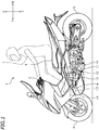
- a straddled vehicle is a scooter-type motorcycle 1 .
- the motorcycle 1 includes a vehicle frame (not shown) having a head pipe (not shown), a steering handle 3 supported on the head pipe so that the steering handle 3 can rotate left and right, a front wheel 4 , a rear wheel 5 , a seat 6 , and an internal combustion engine 10 .
- front, rear, left, right, up and down refer to front, rear, left, right, up and down, respectively, as seen from a virtual passenger 7 seated on the seat 6 while the motorcycle 1 is standing upright on a horizontal surface with no load thereon, unless specified otherwise. Note that no load means that there is no passenger 7 on the motorcycle 1 and the motorcycle 1 has no fuel.
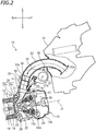
- the internal combustion engine 10 includes a crankcase 11 , a cylinder body 12 and a cylinder head 13 .
- the cylinder head 13 is connected to the cylinder body 12
- the cylinder body 12 is connected to the crankcase 11 .
- the cylinder head 13 is arranged forward of the cylinder body 12
- the cylinder body 12 is arranged forward of the crankcase 11 .
- the cylinder head 13 includes a head body 13a and a head cover 13b .
- the head body 13a and the head cover 13b are separate members and are secured to each other. Note however that the head body 13a and the head cover 13b may be integral with each other.
- the cylinder body 12 includes a cylinder 15 .
- a combustion chamber 16 is formed inside the cylinder body 12 and the cylinder head 13 .
- a piston 17 is arranged inside the cylinder 15 .
- a crankshaft (not shown) is arranged inside the crankcase 11 . The piston 17 and the crankshaft are linked together by a connecting rod 18 .
- the internal combustion engine 10 is a 4-cycle 2-cylinder engine.
- the cylinder body 12 includes another cylinder 15 .
- the cylinder 15 and the other cylinder 15 are arranged next to each other in the left-right direction.
- Another piston 17 is arranged inside the other cylinder 15 .
- the other piston 17 and the crankshaft are linked together by another connecting rod 18 .
- the designation L4 represents the center line of the cylinder 15 (hereinafter referred to as the cylinder center line).
- the angle ⁇ formed between the horizontal line L0 and the cylinder center line L4 is 45 degrees or less.
- an angle formed between two straight lines refers to one of the two angles formed by the two straight lines (i.e., two angles that are supplementary to each other) that is 90 degrees or less.
- ⁇ may be 30 degrees or less, may be 15 degrees or less, or may be 10 degrees or less.
- the cylinder head 13 includes an intake port 21 and an exhaust port 22 that communicate with the inside of the cylinder 15 .
- An intake opening 23 facing the combustion chamber 16 is formed at the downstream end of the intake port 21 in the flow direction of the intake air.
- An exhaust opening 24 facing the combustion chamber 16 is formed at the upstream end of the exhaust port 22 in the flow direction of the exhaust air.
- Supported on the cylinder head 13 are an intake valve 25 for opening/closing the intake opening 23 of the intake port 21, an exhaust valve 26 for opening/closing the exhaust opening 24 of the exhaust port 22 , an intake camshaft 29 provided with an intake cam 27 for actuating the intake valve 25 , and an exhaust camshaft 28A provided with an exhaust cam 28 for actuating the exhaust valve 26.
- a throttle body 32 is connected to the intake port 21 of the cylinder head 13 via a joint member 31 .
- An intake pipe 33 is connected to the throttle body 32.
- An air cleaner 34 is connected to the intake pipe 33 .
- An upstream end portion 33a of the intake pipe 33 is open inside the air cleaner 34 .
- a downstream end portion 33b of the intake pipe 33 is connected to the throttle body 32 .
- the intake pipe 33 , the throttle body 32 , the joint member 31 and the intake port 21 together form an intake passage 39 extending from the air cleaner 34 to the combustion chamber 16 .
- the intake passage 39 is a so-called downdraft intake passage.
- a throttle valve 35 is arranged inside the throttle body 32 .
- the throttle valve 35 is provided with a valve shaft 36 .
- the valve shaft 36 is rotatably supported on the throttle body 32 .
- the valve shaft 36 is arranged parallel to the intake camshaft 29 and the exhaust camshaft 28A.
- the internal combustion engine 10 is a 2-cylinder engine.
- the internal combustion engine 10 includes another intake port 21 , another exhaust port 22 , another intake valve 25 , another exhaust valve 26 , another intake cam 27 and another exhaust cam 28 . These components are similar to their counterparts described above, and will not be described below.
- the other intake cam 27 is provided on the intake camshaft 29
- the other exhaust cam 28 is provided on the exhaust camshaft 28A .
- the internal combustion engine 10 includes another joint member 31 , another throttle body 32 and another intake pipe 33 . These components are also similar to their counterparts described above, and will not be described below.
- Another throttle valve 35 is arranged inside the other throttle body 32 . Note that the other throttle valve 35 is connected to the valve shaft 36 .
- the two throttle valves 35 are linked together by the valve shaft 36 .
- the internal combustion engine 1 includes an electric motor 37 as an actuator for actuating the throttle valve 35 and the other throttle valve 35 .
- a rotation shaft 37s of the motor 37 and the valve shaft 36 are arranged parallel to each other. As shown in FIG. 3 , the rotation shaft 37s of the motor 37 and the valve shaft 36 are linked together by a power transmission mechanism 30 . With the power transmission mechanism 30 interposed between the motor 37 and the valve shaft 36 , the motor 37 is arranged at a position relatively far away from the throttle valve 35 .
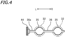
- the power transmission mechanism 30 includes a first gear 41 linked to the rotation shaft 37s of the motor 37 , a second gear 42 linked to the first gear 41 , a third gear 43 linked to the second gear 42 , and a fourth gear 44 linked to the third gear 43 .
- the fourth gear 44 is linked to the valve shaft 36 .
- the first gear 41 is an example of the driving link portion linked to the actuator.
- the fourth gear 44 is an example of the driven link portion linked to the valve shaft 36 .
- the power transmission mechanism 30 is configured to transmit the driving force of the motor 37 to the valve shaft 36 .
- the throttle valve 35 and the other throttle valve 35 are driven by the motor 37 to rotate. As shown in FIG.
- the valve shaft 36 includes a shaft end portion 36a extending away from the throttle valve 35 and the other throttle valve 35 .
- the shaft end portion 36a extends leftward from both throttle valves 35 .
- the fourth gear 44 is linked to the shaft end portion 36a .
- the first to fourth gears 41 to 44 are accommodated in a gearbox 45 .
- the gearbox 45 is arranged leftward of the two throttle bodies 32 .
- the motor 37 is arranged rightward of the gearbox 45 .
- a portion of the motor 37 overlaps with the left intake pipe 33 .
- another portion of the motor 37 is arranged between the left intake pipe 33 and the right intake pipe 33 .
- the air cleaner 34 is arranged forward relative to the cylinder head 13 .
- at least a portion of the motor 37 is arranged forward relative to the cylinder head 13 .
- at least a portion of the motor 37 is arranged rearward relative to the air cleaner 34 .
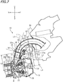
- the internal combustion engine 10 includes a fuel injector 50 . Since the internal combustion engine 10 is a 2-cylinder engine, it includes two fuel injectors 50 . The two fuel injectors 50 are arranged next to each other in the left-right direction. The fuel injectors 50 are attached to the respective throttle bodies 32 .
- the fuel injector 50 includes an injection port 51 for injecting fuel.
- the injection port 51 is arranged on the side of the intake valve 25 relative to the valve shaft 36 in the flow direction of the intake air in the intake passage 39 . In other words, the injection port 51 is arranged on the downstream side of the intake passage 39 relative to the valve shaft 36 .
- the intake valve 25 includes a shaft portion 25a , and an umbrella portion 25b provided at the distal end of the shaft portion 25a for opening/closing the intake opening 23 .
- the fuel injector 50 is arranged so that the center line L3 of the injection port 51 intersects with the umbrella portion 25b when the intake valve 25 closes the intake opening 23 .
- the angle ⁇ formed between the center line L3 of the injection port 51 and the cylinder center line L4 is set to be 60 degrees or less.
- the point at which the center line of the shaft portion 25a of the intake valve 25 and the distal end of the umbrella portion 25b intersect with each other is denoted as the first point, the center 37c of the rotation shaft 37s of the motor 37 as the second point, and the center of the valve shaft 36 as the third point.
- the injection port 51 is arranged inside the triangle whose vertexes are the first to third points.
- the injection port 51 is arranged at a position closer to the intake opening 23 than the valve shaft 36 .
- the valve shaft 36 is arranged at a position closer to the intake opening 23 than the rotation shaft 37s of the motor 37 .
- the injection port 51 is arranged downward relative to the valve shaft 36
- the valve shaft 36 is arranged downward relative to the rotation shaft 37s of the motor 37 .
- the motor 37 and the fuel injector 50 are arranged so as not to protrude, relative to the intake passage 39 , on the side opposite to the cylinder head 13 .
- the motor 37 and the fuel injector 50 are arranged on the side of the cylinder head 13 with respect to the center line L1 of the throttle body 32 .
- the motor 37 and the fuel injector 50 are arranged forward of the center line L1 of the throttle body 32 .
- the motor 37 is arranged on the side opposite to the cylinder head 13 with respect to the straight line L2 , which passes through the axis of the valve shaft 36 and is perpendicular to the center line L1 of the throttle body 32 .
- the motor 37 is arranged upward of the straight line L2 .
- the valve shaft 36 is arranged on the side of the cylinder body 12 with respect to the straight line L5 , which passes through the axis of the intake camshaft 29 and is perpendicular to the cylinder center line L4 .
- the valve shaft 36 is arranged rearward of the straight line L5 .
- the motor 37 has a first end portion 37a and a second end portion 37b that intersect with the straight line L6 , which passes through the center 37c of the motor 37 (i.e., the center of the rotation shaft 37s of the motor 37 ) and is perpendicular to the cylinder center line L4 .
- the second end portion 37b is farther away from the cylinder center line L4 than the first end portion 37a .
- the distance K2 between the second end portion 37b and the cylinder center line L4 is longer than the distance K1 between the first end portion 37a and the cylinder center line L4 . K2>K1.
- the distance K3 between the axis of the valve shaft 36 and the cylinder center line L4 is shorter than the distance K2 between the second end portion 37b and the cylinder center line L4 .
- the distance between the throttle valve 35 and the intake port 21 is short.
- the center line 33c of the intake pipe 33 includes a first portion 331 intersecting with the straight line L11 , which passes through the center of the first gear 41 and is perpendicular to the cylinder center line L4 , a second portion 332 intersecting with the straight line L12 , which passes through the center of the second gear 42 and is perpendicular to the cylinder center line L4 , and a third portion 333 intersecting with the straight line L13 , which passes through the center of the third gear 43 and is perpendicular to the cylinder center line L4 .
- the second portion 332 is located on the side of the intake port 21 relative to the first portion 331 .
- the third portion 333 is located on the side of the intake port 21 relative to the second portion 332 .
- the second portion 332 is located rearward and downward of the first portion 331 .
- the third portion 333 is located rearward and downward of the second portion 332 .
- the first gear 41 , the second gear 42 and the third gear 43 are arranged in this order in the flow direction of the intake air through the intake pipe 33 .
- the power transmission mechanism 30 is arranged at a position overlapping with the fuel injector 50 , as seen along the axial direction of the intake camshaft 29 .
- the air cleaner 34 is arranged on the side opposite to the cylinder body 12 with respect to the straight line L7 , which passes through a portion 13f of the cylinder head 13 that is farthest away from the cylinder body 12 and is perpendicular to the cylinder center line L4 .
- the air cleaner 34 is arranged forward of the straight line L7 .
- the power transmission mechanism 30 is interposed between the motor 37 and the valve shaft 36 , and the motor 37 is arranged at a position relatively far away from the throttle body 32 .
- the fuel injector 50 is arranged in the space between the motor 37 and the throttle body 32 , which is created as the motor 37 is moved away from the throttle body 32 .
- the throttle body 32 and the fuel injector 50 can be arranged at positions that are optimal design-wise while minimizing the influence on the peripheral components of the throttle body 32 and the fuel injector 50 . Effects of the internal combustion engine 10 according to the present embodiment will now be described.
- the motor 37 and the fuel injector 50 are arranged on the side of the cylinder head 13 with respect to the intake passage 39 , as seen along the axial direction of the intake camshaft 29 . Therefore, the motor 37 and the fuel injector 50 do not protrude on the side opposite to the cylinder head 13 with respect to the intake passage 39 . Herein, the motor 37 and the fuel injector 50 do not protrude upward of the intake passage 39 . Therefore, it is possible to realize a compact arrangement of the motor 37 and the fuel injector 50 .
- the fuel injector 50 is arranged on the side of the cylinder head 13 with respect to the intake passage 39 , the angle ⁇ formed between the injection direction L3 of the fuel injector 50 and the cylinder center line L4 can be made relatively small. Then, it is possible to realize a desirable injection direction of the fuel injector 50 .
- the internal combustion engine 10 it is possible to both realize a compact arrangement of the motor 37 and the fuel injector 50 and realize a desirable injection direction of the fuel injector 50 .
- the valve shaft 36 is arranged on the side of the cylinder body 12 with respect to the straight line L5 .
- the distance K3 between the axis of the valve shaft 36 and the center line L4 of the cylinder 15 is shorter than the distance K2 between the second end portion 37b of the motor 37 and the center line L4 of the cylinder 15 .
- the distance between the throttle valve 35 and the intake port 21 is short. Since the distance between the throttle valve 35 and the intake port 21 is short, the internal combustion engine 10 can be made compact.
- valve shaft 36 and the rotation shaft 37s of the motor 37 are arranged parallel to each other. Therefore, the motor 37 can be arranged in a compact arrangement.
- the fuel injector 50 is arranged so that the center line L3 of the injection port 51 intersects with the umbrella portion 25b when the intake valve 25 closes the intake opening 23 . Therefore, it is possible to suppress adhesion of fuel injected from the injection port 51 on the wall surface of the intake port 21 . Thus, it is possible to improve the performance of the internal combustion engine 10 .
- the angle ⁇ formed between the center line L3 of the injection port 51 and the cylinder center line L4 is 60 degrees or less.
- the second portion 332 of the center line 33c of the intake pipe 33 is located on the side of the intake port 21 relative to the first portion 331
- the third portion 333 is located on the side of the intake port 21 relative to the second portion 332 .
- the first gear 41 , the second gear 42 and the third gear 43 of the power transmission mechanism 30 are arranged in this order from the upstream side toward the downstream side in the flow direction of the intake air of the intake pipe 33 .
- the motor 37 can be arranged farther away from the cylinder head 13 , and the first to third gears 41 to 43 can be arranged along the intake pipe 33 . Therefore, the motor 37 and the power transmission mechanism 30 can be arranged in a compact arrangement.
- the power transmission mechanism 30 is arranged at a position overlapping with the fuel injector 50 , as seen along the axial direction of the intake camshaft 29 . Therefore, the total dimension in the front-rear direction and the total dimension in the up-down direction of the fuel injector 50 and the power transmission mechanism 30 can be made small. Thus, the fuel injector 50 and the power transmission mechanism 30 can be arranged in a compact arrangement.
- the air cleaner 34 is arranged on the side opposite to the cylinder body 12 with respect to the straight line L7 , which passes through the portion 13f of the cylinder head 13 that is farthest away from the cylinder body 12 and is perpendicular to the cylinder center line L4 . Then, as seen along the axial direction of the intake camshaft 29 , the motor 37 and the fuel injector 50 can be arranged in a compact arrangement in a region that is surrounded by the air cleaner 34 , the cylinder head 13 and the intake passage 39 .
- the motorcycle 1 is not limited to a scooter-type motorcycle but may be a motorcycle of any other type.
- a straddled vehicle refers to a vehicle that is straddled by a passenger, and is not limited to a motorcycle.
- a straddled vehicle may be an ATV (All Terrain Vehicle) or an auto tricycle, for example.
- the power transmission mechanism 30 which connects together the motor 37 and the valve shaft 36 , does not need to include gears. There is no limitation as long as the power transmission mechanism 30 is capable of transmitting the driving force of the motor 37 to the valve shaft 36 .
- the power transmission mechanism 30 may include a transmission belt, for example.
- the actuator for actuating the throttle valve 35 is not limited to the motor 37 .
- the internal combustion engine 10 is not limited to a forward leaning engine.
- the angle ⁇ described above may be greater than 45 degrees.
- the air cleaner 34 does not need to be arranged forward of the cylinder head 13 .
- the air cleaner 34 may be arranged upward of the cylinder head 13 .
- the joint member 31 may be absent between the throttle body 32 and the cylinder head 13 . While the throttle body 32 may be indirectly connected to the intake port 21 of the cylinder head 13 , the throttle body 32 may be directly connected to the intake port 21 of the cylinder head 13 .
- the internal combustion engine 10 is not limited to a 2-cylinder engine.
- the internal combustion engine 10 may be a multi-cylinder engine having three or more cylinders.
- the internal combustion engine 10 may be a single-cylinder engine.
Description
- The present invention relates to an internal combustion engine according to the preamble of independent claim 1 and a straddled vehicle. Such an engine can be taken from the prior art document
JP 2016 180332 A - Conventional internal combustion engines having an actuator for actuating a throttle valve, like the engine of
JP 2009 197816 - The motorcycle includes an intake pipe extending upward from the rear surface of a cylinder head, a throttle body linked to the intake pipe, and an air chamber linked to the throttle body. A motor is arranged rearward of the throttle body. The motor and the valve shaft of the throttle valve are linked together by a link mechanism. A fuel injector is inserted in the intake pipe. A portion of the fuel injector that is located outside the intake pipe is arranged rearward of the intake pipe.
- [Patent Document No. 1]
Japanese Laid-Open Patent Publication No. 2014-159775 - With the internal combustion engine described above, the throttle body and the intake pipe together form an intake passage that links together the air chamber and the intake port of the cylinder head. Both of the motor and the fuel injector are arranged rearward of the intake passage. That is, the motor and the fuel injector are both arranged on one side of the intake passage that is opposite to the side on which the top of the cylinder head is arranged. With the internal combustion engine described above, it may be difficult to both realize a compact arrangement of the motor and the fuel injector and realize a desirable injection direction of the fuel injector.
- It is an object of the present invention, which has been made in view of the above, to provide an internal combustion engine including an actuator for actuating a throttle valve and a fuel injector, wherein it is possible to both realize a compact arrangement of the actuator and the fuel injector and realize a desirable injection direction of the fuel injector, and to provide a straddled vehicle having such an internal combustion engine.
- An internal combustion engine disclosed herein includes: a cylinder body having a cylinder; a cylinder head having an intake port that communicates with the cylinder and connected to the cylinder body; an intake valve supported on the cylinder head for opening/closing the intake port; an intake camshaft supported on the cylinder head and provided with an intake cam for actuating the intake valve; a throttle body connected to the cylinder head and formed with a passage therein; a throttle valve arranged inside the throttle body; a valve shaft provided on the throttle valve and rotatably supported on the throttle body; an actuator for outputting a driving force; a power transmission mechanism having a driving link portion linked to the actuator and a driven link portion linked to the valve shaft for transmitting the driving force of the actuator to the valve shaft; an intake passage including at least the intake port and the passage of the throttle body; and a fuel injector for injecting fuel into the intake passage, wherein the fuel injector has an injection port arranged on a side of the intake valve relative to the valve shaft in a flow direction of an intake air in the intake passage. The actuator and the fuel injector are arranged on a side of the cylinder head with respect to a center line of the throttle body, as seen along an axial direction of the intake camshaft. The actuator is arranged on a side opposite to the cylinder head with respect to a straight line that passes through an axis of the valve shaft and is perpendicular to the center line of the throttle body, as seen along an axial direction of the intake camshaft.
- With the internal combustion engine described above, the actuator and the fuel injector are arranged on the side of the cylinder head with respect to the intake passage, as seen along the axial direction of the intake camshaft. The actuator and the fuel injector do not protrude on the side opposite to the cylinder head with respect to the intake passage. Therefore, it is possible to realize a compact arrangement of the actuator and the fuel injector. Since the fuel injector is arranged on the side of the cylinder head with respect to the intake passage, the angle formed between the injection direction of the fuel injector and the center line of the cylinder can be made relatively small. Then, it is possible to realize a desirable injection direction of the fuel injector. Thus, with the internal combustion engine described above, it is possible to both realize a compact arrangement of the actuator and the fuel injector and realize a desirable injection direction of the fuel injector.
- According to one preferred embodiment, the valve shaft is arranged on a side of the cylinder body with respect to a straight line that passes through an axis of the intake camshaft and is perpendicular to a center line of the cylinder, as seen along an axial direction of the intake camshaft.
- According to one preferred embodiment, the actuator has a motor. As seen along an axial direction of the intake camshaft, the motor includes a first end portion that intersects with a straight line that passes through a center of the motor and is perpendicular to a center line of the cylinder, and a second end portion that intersects with a straight line that passes through the center of the motor and is perpendicular to the center line of the cylinder, wherein the second end portion is farther away from the center line of the cylinder than the first end portion. As seen along an axial direction of the intake camshaft, a distance between the axis of the valve shaft and the center line of the cylinder is shorter than a distance between the second end portion and the center line of the cylinder.
- According to the embodiment described above, the distance between the throttle valve and the intake port is short. Therefore, the internal combustion engine can be made compact.
- According to one preferred embodiment, the actuator includes a motor having a rotation shaft. The valve shaft is arranged parallel to the rotation shaft of the motor.
- According to the embodiment described above, the motor can be arranged in a compact arrangement.
- According to one preferred embodiment, a combustion chamber is formed inside the cylinder body and the cylinder head. The intake port has an intake opening facing the combustion chamber. The intake valve has a shaft portion and an umbrella portion provided at a distal end of the shaft portion for opening/closing the intake opening. As seen along an axial direction of the intake camshaft, the fuel injector is arranged so that a center line of the injection port intersects with the umbrella portion when the intake valve closes the intake opening.
- According to the embodiment described above, it is possible to suppress adhesion of fuel injected from the fuel injector on the wall surface of the intake port, and it is possible to improve the performance of the internal combustion engine.
- According to one preferred embodiment, as seen along an axial direction of the intake camshaft, a smaller one of angles that are formed between a center line of the injection port of the fuel injector and a center line of the cylinder is 60 degrees or less.
- According to the embodiment described above, it is possible to realize a compact arrangement of the fuel injector and realize a desirable injection direction.
- According to one preferred embodiment, the internal combustion engine described above includes an intake pipe having an upstream end portion and a downstream end portion that is connected to the throttle body. The power transmission mechanism includes a first gear linked to the actuator, a second gear linked to the first gear, and a third gear linked to the second gear. As seen along an axial direction of the intake camshaft, a center line of the intake pipe includes a first portion that intersects with a straight line that passes through a center of the first gear and is perpendicular to a center line of the cylinder, a second portion that intersects with a straight line that passes through a center of the second gear and is perpendicular to a center line of the cylinder, and a third portion that intersects with a straight line that passes through a center of the third gear and is perpendicular to the center line of the cylinder. The second portion is located on a side of the intake port relative to the first portion, and the third portion is located on the side of the intake port relative to the second portion.
- According to the embodiment described above, the actuator can be arranged farther away from the cylinder head. The first to third gears can be arranged along the intake pipe, and the actuator and the power transmission mechanism can be arranged in a compact arrangement.
- According to one preferred embodiment, the power transmission mechanism is arranged at a position overlapping with the fuel injector, as seen along an axial direction of the intake camshaft.
- According to the embodiment described above, the fuel injector and the power transmission mechanism can be arranged in a compact arrangement.
- According to one preferred embodiment, the cylinder body includes another cylinder. The cylinder head has another intake port that communicates with the other cylinder. The internal combustion engine further includes another intake valve supported on the cylinder head for opening/closing the other intake port. The intake camshaft is provided with another intake cam for actuating the other intake valve. The internal combustion engine includes another throttle body connected to the cylinder head, and another throttle valve arranged inside the other throttle body and linked to the valve shaft. The valve shaft has a shaft end portion extending away from the throttle valve and the other throttle valve. The power transmission mechanism is linked to the shaft end portion.
- According to the embodiment described above, while having a plurality of cylinders, it is possible to both realize a compact arrangement of the actuator and the fuel injector and realize a desirable injection direction of the fuel injector.
- According to one preferred embodiment, the internal combustion engine includes an air cleaner connected to the intake passage. As seen along an axial direction of the intake camshaft, the air cleaner is arranged on a side opposite to the cylinder body with respect to a straight line that passes through a portion of the cylinder head that is farthest away from the cylinder body and is perpendicular to a center line of the cylinder.
- According to the embodiment described above, as seen along the axial direction of the intake camshaft, the actuator and the fuel injector can be arranged in a compact arrangement in a region that is surrounded by the air cleaner, the cylinder head and the intake passage.
- A straddled vehicle disclosed herein includes the internal combustion engine described above, wherein the cylinder head is arranged forward relative to the cylinder body in a vehicle front-rear direction, and the air cleaner is arranged forward relative to the cylinder head in the vehicle front-rear direction.
- According to the embodiment described above, the effects described above can be realized with so-called forward leaning engines.
- According to the present invention, it is possible to provide an internal combustion engine including an actuator for actuating a throttle valve and a fuel injector, wherein it is possible to both realize a compact arrangement of the actuator and the fuel injector and realize a desirable injection direction of the fuel injector, and to provide a straddled vehicle having such an internal combustion engine.
-
- [
FIG. 1 ] A side view of a motorcycle according to one embodiment. - [
FIG. 2 ] A partial cross-sectional view of an internal combustion engine of the motorcycle. - [
FIG. 3 ] A cross-sectional view of a power transmission mechanism. - [
FIG. 4 ] A schematic diagram showing a link between a gear of a power transmission mechanism and a valve shaft of a throttle valve. - [
FIG. 5 ] A partial perspective view of the internal combustion engine. - [
FIG. 6 ] A partial plan view of the internal combustion engine. - [
FIG. 7 ] A partial cross-sectional view of the internal combustion engine. - One embodiment will now be described with reference to the drawings. As shown in
FIG. 1 , a straddled vehicle according to the present embodiment is a scooter-type motorcycle 1. The motorcycle 1 includes a vehicle frame (not shown) having a head pipe (not shown), asteering handle 3 supported on the head pipe so that the steering handle 3 can rotate left and right, afront wheel 4, arear wheel 5, a seat 6, and aninternal combustion engine 10. - The terms front, rear, left, right, up and down, as used in the description below, refer to front, rear, left, right, up and down, respectively, as seen from a
virtual passenger 7 seated on the seat 6 while the motorcycle 1 is standing upright on a horizontal surface with no load thereon, unless specified otherwise. Note that no load means that there is nopassenger 7 on the motorcycle 1 and the motorcycle 1 has no fuel. The designations F, Rr, L, R, U and D, as used in the figures, refer to front, rear, left, right, up and down, respectively. - The
internal combustion engine 10 includes acrankcase 11, acylinder body 12 and acylinder head 13. Thecylinder head 13 is connected to thecylinder body 12, and thecylinder body 12 is connected to thecrankcase 11. In the present embodiment, thecylinder head 13 is arranged forward of thecylinder body 12, and thecylinder body 12 is arranged forward of thecrankcase 11. - As shown in
FIG. 2 , thecylinder head 13 includes ahead body 13a and ahead cover 13b. In the present embodiment, thehead body 13a and thehead cover 13b are separate members and are secured to each other. Note however that thehead body 13a and thehead cover 13b may be integral with each other. Thecylinder body 12 includes acylinder 15. Acombustion chamber 16 is formed inside thecylinder body 12 and thecylinder head 13. Apiston 17 is arranged inside thecylinder 15. A crankshaft (not shown) is arranged inside thecrankcase 11. Thepiston 17 and the crankshaft are linked together by a connectingrod 18. - The
internal combustion engine 10 is a 4-cycle 2-cylinder engine. Although not shown in the drawings, thecylinder body 12 includes anothercylinder 15. Thecylinder 15 and theother cylinder 15 are arranged next to each other in the left-right direction. Anotherpiston 17 is arranged inside theother cylinder 15. Theother piston 17 and the crankshaft are linked together by another connectingrod 18. - The designation L4 represents the center line of the cylinder 15 (hereinafter referred to as the cylinder center line). As shown in
FIG. 1 , in the present embodiment, the angle α formed between the horizontal line L0 and the cylinder center line L4, as the vehicle is seen from the side, is 45 degrees or less. Note that an angle formed between two straight lines, as used in the present specification, refers to one of the two angles formed by the two straight lines (i.e., two angles that are supplementary to each other) that is 90 degrees or less. α may be 30 degrees or less, may be 15 degrees or less, or may be 10 degrees or less. - As shown in
FIG. 2 , thecylinder head 13 includes anintake port 21 and anexhaust port 22 that communicate with the inside of thecylinder 15. Anintake opening 23 facing thecombustion chamber 16 is formed at the downstream end of theintake port 21 in the flow direction of the intake air. Anexhaust opening 24 facing thecombustion chamber 16 is formed at the upstream end of theexhaust port 22 in the flow direction of the exhaust air. Supported on thecylinder head 13 are anintake valve 25 for opening/closing theintake opening 23 of theintake port 21, anexhaust valve 26 for opening/closing theexhaust opening 24 of theexhaust port 22, anintake camshaft 29 provided with anintake cam 27 for actuating theintake valve 25, and anexhaust camshaft 28A provided with anexhaust cam 28 for actuating theexhaust valve 26. - A
throttle body 32 is connected to theintake port 21 of thecylinder head 13 via ajoint member 31. Anintake pipe 33 is connected to thethrottle body 32. Anair cleaner 34 is connected to theintake pipe 33. Anupstream end portion 33a of theintake pipe 33 is open inside theair cleaner 34. Adownstream end portion 33b of theintake pipe 33 is connected to thethrottle body 32. Theintake pipe 33, thethrottle body 32, thejoint member 31 and theintake port 21 together form anintake passage 39 extending from theair cleaner 34 to thecombustion chamber 16. Theintake passage 39 is a so-called downdraft intake passage. - A passage, through which the intake air passes, is formed inside the
throttle body 32. Athrottle valve 35 is arranged inside thethrottle body 32. Thethrottle valve 35 is provided with avalve shaft 36. Thevalve shaft 36 is rotatably supported on thethrottle body 32. Thevalve shaft 36 is arranged parallel to theintake camshaft 29 and theexhaust camshaft 28A. - As described above, the
internal combustion engine 10 is a 2-cylinder engine. Theinternal combustion engine 10 includes anotherintake port 21, anotherexhaust port 22, anotherintake valve 25, anotherexhaust valve 26, anotherintake cam 27 and anotherexhaust cam 28. These components are similar to their counterparts described above, and will not be described below. Theother intake cam 27 is provided on theintake camshaft 29, and theother exhaust cam 28 is provided on theexhaust camshaft 28A. Theinternal combustion engine 10 includes anotherjoint member 31, anotherthrottle body 32 and anotherintake pipe 33. These components are also similar to their counterparts described above, and will not be described below. Anotherthrottle valve 35 is arranged inside theother throttle body 32. Note that theother throttle valve 35 is connected to thevalve shaft 36. The twothrottle valves 35 are linked together by thevalve shaft 36. - The internal combustion engine 1 includes an
electric motor 37 as an actuator for actuating thethrottle valve 35 and theother throttle valve 35. Arotation shaft 37s of themotor 37 and thevalve shaft 36 are arranged parallel to each other. As shown inFIG. 3 , therotation shaft 37s of themotor 37 and thevalve shaft 36 are linked together by apower transmission mechanism 30. With thepower transmission mechanism 30 interposed between themotor 37 and thevalve shaft 36, themotor 37 is arranged at a position relatively far away from thethrottle valve 35. Thepower transmission mechanism 30 according to the present embodiment includes afirst gear 41 linked to therotation shaft 37s of themotor 37, asecond gear 42 linked to thefirst gear 41, athird gear 43 linked to thesecond gear 42, and afourth gear 44 linked to thethird gear 43. Thefourth gear 44 is linked to thevalve shaft 36. Note that thefirst gear 41 is an example of the driving link portion linked to the actuator. Thefourth gear 44 is an example of the driven link portion linked to thevalve shaft 36. Thepower transmission mechanism 30 is configured to transmit the driving force of themotor 37 to thevalve shaft 36. Thethrottle valve 35 and theother throttle valve 35 are driven by themotor 37 to rotate. As shown inFIG. 4 , thevalve shaft 36 includes ashaft end portion 36a extending away from thethrottle valve 35 and theother throttle valve 35. Herein, theshaft end portion 36a extends leftward from boththrottle valves 35. Thefourth gear 44 is linked to theshaft end portion 36a. - The first to
fourth gears 41 to 44 are accommodated in agearbox 45. As shown inFIG. 5 , thegearbox 45 is arranged leftward of the twothrottle bodies 32. As shown inFIG. 6 , themotor 37 is arranged rightward of thegearbox 45. As seen from above, a portion of themotor 37 overlaps with theleft intake pipe 33. As seen from above, another portion of themotor 37 is arranged between theleft intake pipe 33 and theright intake pipe 33. As seen from above, theair cleaner 34 is arranged forward relative to thecylinder head 13. As seen from above, at least a portion of themotor 37 is arranged forward relative to thecylinder head 13. As seen from above, at least a portion of themotor 37 is arranged rearward relative to theair cleaner 34. - As shown in
FIG. 2 , theinternal combustion engine 10 includes afuel injector 50. Since theinternal combustion engine 10 is a 2-cylinder engine, it includes twofuel injectors 50. The twofuel injectors 50 are arranged next to each other in the left-right direction. Thefuel injectors 50 are attached to therespective throttle bodies 32. Thefuel injector 50 includes aninjection port 51 for injecting fuel. Theinjection port 51 is arranged on the side of theintake valve 25 relative to thevalve shaft 36 in the flow direction of the intake air in theintake passage 39. In other words, theinjection port 51 is arranged on the downstream side of theintake passage 39 relative to thevalve shaft 36. - The
intake valve 25 includes ashaft portion 25a, and anumbrella portion 25b provided at the distal end of theshaft portion 25a for opening/closing theintake opening 23. As shown inFIG. 7 , as seen along the axial direction of theintake camshaft 29, thefuel injector 50 is arranged so that the center line L3 of theinjection port 51 intersects with theumbrella portion 25b when theintake valve 25 closes theintake opening 23. As seen along the axial direction of theintake camshaft 29, the angle θ formed between the center line L3 of theinjection port 51 and the cylinder center line L4 is set to be 60 degrees or less. - As seen along the axial direction of the
intake camshaft 29, the point at which the center line of theshaft portion 25a of theintake valve 25 and the distal end of theumbrella portion 25b intersect with each other is denoted as the first point, thecenter 37c of therotation shaft 37s of themotor 37 as the second point, and the center of thevalve shaft 36 as the third point. As seen along the axial direction of theintake camshaft 29, theinjection port 51 is arranged inside the triangle whose vertexes are the first to third points. - As shown in
FIG. 2 , theinjection port 51 is arranged at a position closer to theintake opening 23 than thevalve shaft 36. Thevalve shaft 36 is arranged at a position closer to theintake opening 23 than therotation shaft 37s of themotor 37. Herein, theinjection port 51 is arranged downward relative to thevalve shaft 36, and thevalve shaft 36 is arranged downward relative to therotation shaft 37s of themotor 37. - As shown in
FIG. 7 , as seen along the axial direction of theintake camshaft 29, themotor 37 and thefuel injector 50 are arranged so as not to protrude, relative to theintake passage 39, on the side opposite to thecylinder head 13. As seen along the axial direction of theintake camshaft 29, themotor 37 and thefuel injector 50 are arranged on the side of thecylinder head 13 with respect to the center line L1 of thethrottle body 32. Herein, themotor 37 and thefuel injector 50 are arranged forward of the center line L1 of thethrottle body 32. As seen along the axial direction of theintake camshaft 29, themotor 37 is arranged on the side opposite to thecylinder head 13 with respect to the straight line L2, which passes through the axis of thevalve shaft 36 and is perpendicular to the center line L1 of thethrottle body 32. Herein, themotor 37 is arranged upward of the straight line L2. - As seen along the axial direction of the
intake camshaft 29, thevalve shaft 36 is arranged on the side of thecylinder body 12 with respect to the straight line L5, which passes through the axis of theintake camshaft 29 and is perpendicular to the cylinder center line L4. Herein, thevalve shaft 36 is arranged rearward of the straight line L5. As described above, with theinternal combustion engine 10 according to the present embodiment, the distance between thethrottle valve 35 and theintake port 21 is short. - As seen along the axial direction of the
intake camshaft 29, themotor 37 has afirst end portion 37a and asecond end portion 37b that intersect with the straight line L6, which passes through thecenter 37c of the motor 37 (i.e., the center of therotation shaft 37s of the motor 37) and is perpendicular to the cylinder center line L4. Thesecond end portion 37b is farther away from the cylinder center line L4 than thefirst end portion 37a. The distance K2 between thesecond end portion 37b and the cylinder center line L4 is longer than the distance K1 between thefirst end portion 37a and the cylinder center line L4. K2>K1. As seen along the axial direction of theintake camshaft 29, the distance K3 between the axis of thevalve shaft 36 and the cylinder center line L4 is shorter than the distance K2 between thesecond end portion 37b and the cylinder center line L4. K3<K2. As described above, with the internal combustion engine 1 according to the present embodiment, the distance between thethrottle valve 35 and theintake port 21 is short. - As shown in
FIG. 3 , as seen along the axial direction of theintake camshaft 29, thecenter line 33c of theintake pipe 33 includes afirst portion 331 intersecting with the straight line L11, which passes through the center of thefirst gear 41 and is perpendicular to the cylinder center line L4, asecond portion 332 intersecting with the straight line L12, which passes through the center of thesecond gear 42 and is perpendicular to the cylinder center line L4, and athird portion 333 intersecting with the straight line L13, which passes through the center of thethird gear 43 and is perpendicular to the cylinder center line L4. Thesecond portion 332 is located on the side of theintake port 21 relative to thefirst portion 331. Thethird portion 333 is located on the side of theintake port 21 relative to thesecond portion 332. Herein, thesecond portion 332 is located rearward and downward of thefirst portion 331. Thethird portion 333 is located rearward and downward of thesecond portion 332. Thus, thefirst gear 41, thesecond gear 42 and thethird gear 43 are arranged in this order in the flow direction of the intake air through theintake pipe 33. - As shown in
FIG. 2 andFIG. 3 , thepower transmission mechanism 30 is arranged at a position overlapping with thefuel injector 50, as seen along the axial direction of theintake camshaft 29. - As shown in
FIG. 7 , as seen along the axial direction of theintake camshaft 29, theair cleaner 34 is arranged on the side opposite to thecylinder body 12 with respect to the straight line L7, which passes through aportion 13f of thecylinder head 13 that is farthest away from thecylinder body 12 and is perpendicular to the cylinder center line L4. Herein, theair cleaner 34 is arranged forward of the straight line L7. - As described above, with the
internal combustion engine 10 according to the present embodiment, thepower transmission mechanism 30 is interposed between themotor 37 and thevalve shaft 36, and themotor 37 is arranged at a position relatively far away from thethrottle body 32. Then, thefuel injector 50 is arranged in the space between themotor 37 and thethrottle body 32, which is created as themotor 37 is moved away from thethrottle body 32. With theinternal combustion engine 10, thethrottle body 32 and thefuel injector 50 can be arranged at positions that are optimal design-wise while minimizing the influence on the peripheral components of thethrottle body 32 and thefuel injector 50. Effects of theinternal combustion engine 10 according to the present embodiment will now be described. - As shown in
FIG. 7 , with theinternal combustion engine 10 according to the present embodiment, themotor 37 and thefuel injector 50 are arranged on the side of thecylinder head 13 with respect to theintake passage 39, as seen along the axial direction of theintake camshaft 29. Therefore, themotor 37 and thefuel injector 50 do not protrude on the side opposite to thecylinder head 13 with respect to theintake passage 39. Herein, themotor 37 and thefuel injector 50 do not protrude upward of theintake passage 39. Therefore, it is possible to realize a compact arrangement of themotor 37 and thefuel injector 50. Since thefuel injector 50 is arranged on the side of thecylinder head 13 with respect to theintake passage 39, the angle θ formed between the injection direction L3 of thefuel injector 50 and the cylinder center line L4 can be made relatively small. Then, it is possible to realize a desirable injection direction of thefuel injector 50. Thus, with theinternal combustion engine 10 according to the present embodiment, it is possible to both realize a compact arrangement of themotor 37 and thefuel injector 50 and realize a desirable injection direction of thefuel injector 50. - As shown in
FIG. 7 , with theinternal combustion engine 10 according to the present embodiment, thevalve shaft 36 is arranged on the side of thecylinder body 12 with respect to the straight line L5. The distance K3 between the axis of thevalve shaft 36 and the center line L4 of thecylinder 15 is shorter than the distance K2 between thesecond end portion 37b of themotor 37 and the center line L4 of thecylinder 15. With theinternal combustion engine 10 according to the present embodiment, the distance between thethrottle valve 35 and theintake port 21 is short. Since the distance between thethrottle valve 35 and theintake port 21 is short, theinternal combustion engine 10 can be made compact. - With the
internal combustion engine 10 according to the present embodiment, thevalve shaft 36 and therotation shaft 37s of themotor 37 are arranged parallel to each other. Therefore, themotor 37 can be arranged in a compact arrangement. - As described above, as seen along the axial direction of the
intake camshaft 29, thefuel injector 50 is arranged so that the center line L3 of theinjection port 51 intersects with theumbrella portion 25b when theintake valve 25 closes theintake opening 23. Therefore, it is possible to suppress adhesion of fuel injected from theinjection port 51 on the wall surface of theintake port 21. Thus, it is possible to improve the performance of theinternal combustion engine 10. - With the
internal combustion engine 10, as seen along the axial direction of theintake camshaft 29, the angle θ formed between the center line L3 of theinjection port 51 and the cylinder center line L4 is 60 degrees or less. With theinternal combustion engine 10, it is possible to realize a compact arrangement of thefuel injector 50 and realize a desirable injection direction. - As shown in
FIG. 3 , thesecond portion 332 of thecenter line 33c of theintake pipe 33 is located on the side of theintake port 21 relative to thefirst portion 331, and thethird portion 333 is located on the side of theintake port 21 relative to thesecond portion 332. Thefirst gear 41, thesecond gear 42 and thethird gear 43 of thepower transmission mechanism 30 are arranged in this order from the upstream side toward the downstream side in the flow direction of the intake air of theintake pipe 33. With such an arrangement of the first tothird gears 41 to 43, themotor 37 can be arranged farther away from thecylinder head 13, and the first tothird gears 41 to 43 can be arranged along theintake pipe 33. Therefore, themotor 37 and thepower transmission mechanism 30 can be arranged in a compact arrangement. - The
power transmission mechanism 30 is arranged at a position overlapping with thefuel injector 50, as seen along the axial direction of theintake camshaft 29. Therefore, the total dimension in the front-rear direction and the total dimension in the up-down direction of thefuel injector 50 and thepower transmission mechanism 30 can be made small. Thus, thefuel injector 50 and thepower transmission mechanism 30 can be arranged in a compact arrangement. - As shown in
FIG. 7 , as seen along the axial direction of theintake camshaft 29, theair cleaner 34 is arranged on the side opposite to thecylinder body 12 with respect to the straight line L7, which passes through theportion 13f of thecylinder head 13 that is farthest away from thecylinder body 12 and is perpendicular to the cylinder center line L4. Then, as seen along the axial direction of theintake camshaft 29, themotor 37 and thefuel injector 50 can be arranged in a compact arrangement in a region that is surrounded by theair cleaner 34, thecylinder head 13 and theintake passage 39. - Although one embodiment of the present invention has been described above, the present invention is not limited to the embodiment described above. Next, examples of other embodiments will be described briefly.
- The motorcycle 1 is not limited to a scooter-type motorcycle but may be a motorcycle of any other type. A straddled vehicle refers to a vehicle that is straddled by a passenger, and is not limited to a motorcycle. A straddled vehicle may be an ATV (All Terrain Vehicle) or an auto tricycle, for example.
- The
power transmission mechanism 30, which connects together themotor 37 and thevalve shaft 36, does not need to include gears. There is no limitation as long as thepower transmission mechanism 30 is capable of transmitting the driving force of themotor 37 to thevalve shaft 36. Thepower transmission mechanism 30 may include a transmission belt, for example. - There is no limitation on the type of the
motor 37. The actuator for actuating thethrottle valve 35 is not limited to themotor 37. - The
internal combustion engine 10 is not limited to a forward leaning engine. The angle α described above may be greater than 45 degrees. Theair cleaner 34 does not need to be arranged forward of thecylinder head 13. Theair cleaner 34 may be arranged upward of thecylinder head 13. - The
joint member 31 may be absent between thethrottle body 32 and thecylinder head 13. While thethrottle body 32 may be indirectly connected to theintake port 21 of thecylinder head 13, thethrottle body 32 may be directly connected to theintake port 21 of thecylinder head 13. - The
internal combustion engine 10 is not limited to a 2-cylinder engine. Theinternal combustion engine 10 may be a multi-cylinder engine having three or more cylinders. Theinternal combustion engine 10 may be a single-cylinder engine. - The terms and expressions used herein are used for explanation purposes and should not be construed as being restrictive. It should be appreciated that the terms and expressions used herein do not eliminate any equivalents of features illustrated and mentioned herein, but include various modifications falling within the claimed scope of the present invention. The present invention may be embodied in many different forms. The present disclosure is to be considered as providing examples of the principles of the invention. These examples are described herein with the understanding that such examples are not intended to limit the present invention to preferred embodiments described herein and/or illustrated herein. Hence, the present invention is not limited to the preferred embodiments described herein. The invention is defined by the appended claims.
- 1: Motorcycle (straddled vehicle), 10: Internal combustion engine, 12: Cylinder body, 13: Cylinder head, 15: Cylinder, 16: Combustion chamber, 21: Intake port, 23: Intake opening, 25: Intake valve, 25a: Shaft portion, 25b: Umbrella portion, 27: Intake cam, 29: Intake camshaft, 30: Power transmission mechanism, 32: Throttle body, 33: Intake pipe, 33c: Center line of intake pipe, 34: Air cleaner, 35: Throttle valve, 36: Valve shaft, 36a: Shaft end portion, 37: Motor (actuator), 37a: First end portion, 37b: Second end portion, 37s: Rotation shaft of motor, 37c: Center of motor, 39: Intake passage, 41: First gear (driving link portion), 42: Second gear, 43: Third gear, 44: Fourth gear (driven link portion), 50: Fuel injector, 51: Injection port, 331: First portion, 332: Second portion, 333: Third portion, L1: Center line of throttle body, L2: Straight line that passes through axis of valve shaft and is perpendicular to center line of throttle body, L3: Center line of injection port, L4: Center line of cylinder, L5: Straight line that passes through axis of intake camshaft and is perpendicular to center line of cylinder, L6: Straight line that passes through center of motor and is perpendicular to center line of cylinder, L7: Straight line that passes through portion of cylinder head that is farthest away from cylinder body and is perpendicular to center line of cylinder
Claims (11)
- An internal combustion engine comprising:a cylinder body (12) having a cylinder (15);a cylinder head (13) having an intake port (21) that communicates with the cylinder (15) and connected to the cylinder body (12);an intake valve (25) supported on the cylinder head (13) for opening/closing the intake port (21);an intake camshaft (29) supported on the cylinder head (13) and provided with an intake cam (27) for actuating the intake valve (25);a throttle body (32) connected to the cylinder head (13) and formed with a passage therein;a throttle valve (35) arranged inside the throttle body (32);a valve shaft (36) provided on the throttle valve (35) and rotatably supported on the throttle body (32);an actuator (37) for outputting a driving force;a power transmission mechanism (30) having a driving link portion linked to the actuator (37) and a driven link portion (44) linked to the valve shaft (36) for transmitting the driving force of the actuator (37) to the valve shaft (36);an intake passage (39) including at least the intake port (21) and the passage of the throttle body (32); anda fuel injector (50) for injecting fuel into the intake passage (39), wherein the fuel injector (50) has an injection port (51) arranged on a side of the intake valve (25) relative to the valve shaft (36) in a flow direction of an intake air in the intake passage (39), wherein:as seen along an axial direction of the intake camshaft (29), the actuator (37) is arranged on a side opposite to the cylinder head (13) with respect to a straight line (L2) that passes through an axis of the valve shaft (36) and is perpendicular to a center line (L1) of the throttle body (32), characterized in thatas seen along an axial direction of the intake camshaft (29), the actuator (37) and the fuel injector (50) are arranged on a side of the cylinder head (13) with respect to the center line (L1) of the throttle body (32).
- The internal combustion engine according to claim 1, wherein the valve shaft (36) is arranged on a side of the cylinder body (12) with respect to a straight line (L5) that passes through an axis of the intake camshaft (29) and is perpendicular to a center line (L4) of the cylinder (15), as seen along an axial direction of the intake camshaft (29).
- The internal combustion engine according to claim 1 or 2, wherein the actuator has a motor (37);as seen along an axial direction of the intake camshaft (29), the motor (37) includes a first end portion (37a) that intersects with a straight line that passes through a center of the motor (37) and is perpendicular to a center line (L4) of the cylinder (15), and a second end portion (37b) that intersects with a straight line (L6) that passes through the center (37c) of the motor (37) and is perpendicular to the center line (L4) of the cylinder (15), wherein the second end portion (37b) is farther away from the center line (L4) of the cylinder (15) than the first end portion (37a); andas seen along an axial direction of the intake camshaft (29), a distance (K3) between the axis of the valve shaft (36) and the center line (L4) of the cylinder (15) is shorter than a distance (K2) between the second end portion (37b) and the center line (L4) of the cylinder (15).
- The internal combustion engine according to claim 1 or 2, wherein the actuator includes a motor (37) having a rotation shaft (37s); and
the valve shaft (36) is arranged parallel to the rotation shaft (37s) of the motor (37). - The internal combustion engine according to any one of claims 1 to 4, wherein a combustion chamber (16) is formed inside the cylinder body (12) and the cylinder head (13);the intake port (21) has an intake opening (23) facing the combustion chamber (16);the intake valve (25) has a shaft portion (25a) and an umbrella portion (25b) provided at a distal end of the shaft portion (25a) for opening/closing the intake opening (23); andas seen along an axial direction of the intake camshaft (29), the fuel injector (50) is arranged so that a center line (L3) of the injection port (51) intersects with the umbrella portion (25b) when the intake valve (25) closes the intake opening (23).
- The internal combustion engine according to any one of claims 1 to 5, wherein as seen along an axial direction of the intake camshaft (29), a smaller one of angles that are formed between a center line (L3) of the injection port (51) of the fuel injector (50) and a center line (L4) of the cylinder (15) is 60 degrees or less.
- The internal combustion engine according to any one of claims 1 to 6, comprising an intake pipe (33) having an upstream end portion (33a) and a downstream end portion (33b) that is connected to the throttle body (32), wherein:the power transmission mechanism (30) includes a first gear (41) linked to the actuator (37), a second gear (42) linked to the first gear (41), and a third gear (43) linked to the second gear (42);as seen along an axial direction of the intake camshaft (29), a center line (33c) of the intake pipe (33) includes a first portion (331) that intersects with a straight line (L11) that passes through a center of the first gear (41) and is perpendicular to a center line (L4) of the cylinder (15), a second portion (332) that intersects with a straight line (L12) that passes through a center of the second gear (42) and is perpendicular to a center line (L4) of the cylinder (15), and a third portion (333) that intersects with a straight line (L13) that passes through a center of the third gear (43) and is perpendicular to the center line (L4) of the cylinder (15);the second portion (332) is located on a side of the intake port (21) relative to the first portion (331); andthe third portion (333) is located on the side of the intake port (21) relative to the second portion (332).
- The internal combustion engine according to any one of claims 1 to 7, wherein the power transmission mechanism (30) is arranged at a position overlapping with the fuel injector (50), as seen along an axial direction of the intake camshaft (29).
- The internal combustion engine according to any one of claims 1 to 8, wherein the cylinder body (12) includes another cylinder;the cylinder head (13) has another intake port (21) that communicates with the other cylinder;the internal combustion engine further includes another intake valve supported on the cylinder head (13) for opening/closing the other intake port;the intake camshaft (29) is provided with another intake cam for actuating the other intake valve;the internal combustion engine includes another throttle body connected to the cylinder head (13);the internal combustion engine includes another throttle valve arranged inside the other throttle body and linked to the valve shaft (36);the valve shaft (36) has a shaft end portion (36a) extending away from the throttle valve (35) and the other throttle valve; andthe power transmission mechanism (30) is linked to the shaft end portion (36a).
- The internal combustion engine according to any one of claims 1 to 9, comprising an air cleaner (34) connected to the intake passage (39),
wherein as seen along an axial direction of the intake camshaft (29), the air cleaner (34) is arranged on a side opposite to the cylinder body (12) with respect to a straight line (L7) that passes through a portion (13f) of the cylinder head (13) that is farthest away from the cylinder body (12) and is perpendicular to a center line (L4) of the cylinder (15). - The internal combustion engine according to any one of claims 1 to 9, wherein the internal combustion engine includes an air cleaner (34) connected to the intake passage (39);the cylinder head (13) is arranged forward relative to the cylinder body (12) in a vehicle front-rear direction; andthe air cleaner (34) is arranged forward relative to the cylinder head (13) in the vehicle front-rear direction.
Applications Claiming Priority (2)
| Application Number | Priority Date | Filing Date | Title |
|---|---|---|---|
| JP2017157427 | 2017-08-17 | ||
| PCT/JP2018/029559 WO2019035389A1 (en) | 2017-08-17 | 2018-08-07 | Internal-combustion engine and saddle-type vehicle |
Publications (3)
| Publication Number | Publication Date |
|---|---|
| EP3670877A1 EP3670877A1 (en) | 2020-06-24 |
| EP3670877A4 EP3670877A4 (en) | 2020-08-19 |
| EP3670877B1 true EP3670877B1 (en) | 2021-09-29 |
Family
ID=65362939
Family Applications (1)
| Application Number | Title | Priority Date | Filing Date |
|---|---|---|---|
| EP18846075.2A Active EP3670877B1 (en) | 2017-08-17 | 2018-08-07 | Internal-combustion engine and saddle-type vehicle |
Country Status (3)
| Country | Link |
|---|---|
| EP (1) | EP3670877B1 (en) |
| TW (1) | TWI664349B (en) |
| WO (1) | WO2019035389A1 (en) |
Family Cites Families (11)
| Publication number | Priority date | Publication date | Assignee | Title |
|---|---|---|---|---|
| JP4278151B2 (en) * | 2004-01-20 | 2009-06-10 | 本田技研工業株式会社 | Control method for internal combustion engine |
| JP2008286092A (en) * | 2007-05-17 | 2008-11-27 | Yamaha Motor Co Ltd | Motorcycle |
| JP4989566B2 (en) * | 2008-06-24 | 2012-08-01 | 本田技研工業株式会社 | V-type internal combustion engine having a throttle valve device |
| CN101633388B (en) * | 2008-07-24 | 2012-09-05 | 雅马哈发动机株式会社 | Automatic tumbrel |
| JP2010084665A (en) * | 2008-09-30 | 2010-04-15 | Honda Motor Co Ltd | Throttle valve drive system |
| JP2009197816A (en) * | 2009-06-11 | 2009-09-03 | Yamaha Motor Co Ltd | Engine |
| JP5727828B2 (en) * | 2011-03-23 | 2015-06-03 | 本田技研工業株式会社 | Saddle riding vehicle |
| JP6116090B2 (en) | 2013-02-20 | 2017-04-19 | 本田技研工業株式会社 | Throttle valve drive device for internal combustion engine |
| US9255541B2 (en) * | 2013-04-01 | 2016-02-09 | Ford Global Technologies, Llc | Method and system for engine control |
| JP6340903B2 (en) * | 2014-05-13 | 2018-06-13 | スズキ株式会社 | Engine control device |
| JP6094904B2 (en) * | 2015-03-23 | 2017-03-15 | 本田技研工業株式会社 | Motorcycle |
-
2018
- 2018-08-07 WO PCT/JP2018/029559 patent/WO2019035389A1/en unknown
- 2018-08-07 EP EP18846075.2A patent/EP3670877B1/en active Active
- 2018-08-13 TW TW107128147A patent/TWI664349B/en active
Also Published As
| Publication number | Publication date |
|---|---|
| TW201912926A (en) | 2019-04-01 |
| TWI664349B (en) | 2019-07-01 |
| WO2019035389A1 (en) | 2019-02-21 |
| EP3670877A4 (en) | 2020-08-19 |
| EP3670877A1 (en) | 2020-06-24 |
Similar Documents
| Publication | Publication Date | Title |
|---|---|---|
| US7219657B2 (en) | Fuel routing structure for a V-type engine | |
| US8047180B2 (en) | Intake air control system of V-type internal combustion engine | |
| US8113168B2 (en) | Engine unit and vehicle including the same | |
| US8020531B2 (en) | Electronic throttle control device in V-type internal combustion engine for vehicle | |
| US10151238B2 (en) | Internal combustion engine for saddle-ride type vehicle | |
| US8191515B2 (en) | V-type internal combustion engine including throttle valve device, and vehicle incorporating same | |
| US5109811A (en) | Intake system for multi-cylinder engine | |
| US9988978B2 (en) | Four-cycle multi-cylinder engine | |
| US8042521B2 (en) | Engine unit and vehicle provided with the same | |
| EP3670877B1 (en) | Internal-combustion engine and saddle-type vehicle | |
| WO2018163909A1 (en) | Air intake device for internal combustion engine | |
| JP6865078B2 (en) | Internal combustion engine cylinder head | |
| EP3757382A1 (en) | Straddled vehicle | |
| US7690356B2 (en) | Internal combustion engine | |
| JP3156172U (en) | Engine unit and vehicle equipped with the same | |
| JP2917043B2 (en) | Engine intake system | |
| JP6875439B2 (en) | Fuel injection device layout structure | |
| JP2009092021A (en) | Engine unit and vehicle equipped therewith | |
| WO2023190225A1 (en) | Exhaust device for saddle-ride vehicle | |
| US20230096904A1 (en) | Two-Cylinder Reciprocating Engine | |
| JPS5979058A (en) | Suction device for v-type engine | |
| JP3158106U (en) | Engine unit and vehicle equipped with the same | |
| JP3010053B2 (en) | V-type two-stroke engine | |
| JP2023151362A (en) | internal combustion engine | |
| JPH0388912A (en) | V-form engine of motorcycle |
Legal Events
| Date | Code | Title | Description |
|---|---|---|---|
| STAA | Information on the status of an ep patent application or granted ep patent |
Free format text: STATUS: THE INTERNATIONAL PUBLICATION HAS BEEN MADE |
|
| PUAI | Public reference made under article 153(3) epc to a published international application that has entered the european phase |
Free format text: ORIGINAL CODE: 0009012 |
|
| STAA | Information on the status of an ep patent application or granted ep patent |
Free format text: STATUS: REQUEST FOR EXAMINATION WAS MADE |
|
| 17P | Request for examination filed |
Effective date: 20200217 |
|
| AK | Designated contracting states |
Kind code of ref document: A1 Designated state(s): AL AT BE BG CH CY CZ DE DK EE ES FI FR GB GR HR HU IE IS IT LI LT LU LV MC MK MT NL NO PL PT RO RS SE SI SK SM TR |
|
| AX | Request for extension of the european patent |
Extension state: BA ME |
|
| A4 | Supplementary search report drawn up and despatched |
Effective date: 20200720 |
|
| RIC1 | Information provided on ipc code assigned before grant |
Ipc: F02D 11/10 20060101AFI20200715BHEP Ipc: F02M 35/10 20060101ALI20200715BHEP Ipc: F02M 35/16 20060101ALI20200715BHEP Ipc: F02D 9/10 20060101ALN20200715BHEP |
|
| DAV | Request for validation of the european patent (deleted) | ||
| DAX | Request for extension of the european patent (deleted) | ||
| GRAP | Despatch of communication of intention to grant a patent |
Free format text: ORIGINAL CODE: EPIDOSNIGR1 |
|
| STAA | Information on the status of an ep patent application or granted ep patent |
Free format text: STATUS: GRANT OF PATENT IS INTENDED |
|
| RIC1 | Information provided on ipc code assigned before grant |
Ipc: F02D 11/10 20060101AFI20210416BHEP Ipc: F02M 35/10 20060101ALI20210416BHEP Ipc: F02M 35/16 20060101ALI20210416BHEP Ipc: B62K 11/04 20060101ALI20210416BHEP Ipc: F02D 9/10 20060101ALN20210416BHEP |
|
| INTG | Intention to grant announced |
Effective date: 20210510 |
|
| GRAS | Grant fee paid |
Free format text: ORIGINAL CODE: EPIDOSNIGR3 |
|
| GRAA | (expected) grant |
Free format text: ORIGINAL CODE: 0009210 |
|
| STAA | Information on the status of an ep patent application or granted ep patent |
Free format text: STATUS: THE PATENT HAS BEEN GRANTED |
|
| AK | Designated contracting states |
Kind code of ref document: B1 Designated state(s): AL AT BE BG CH CY CZ DE DK EE ES FI FR GB GR HR HU IE IS IT LI LT LU LV MC MK MT NL NO PL PT RO RS SE SI SK SM TR |
|
| REG | Reference to a national code |
Ref country code: GB Ref legal event code: FG4D |
|
| REG | Reference to a national code |
Ref country code: CH Ref legal event code: EP Ref country code: AT Ref legal event code: REF Ref document number: 1434388 Country of ref document: AT Kind code of ref document: T Effective date: 20211015 |
|
| REG | Reference to a national code |
Ref country code: DE Ref legal event code: R096 Ref document number: 602018024435 Country of ref document: DE |
|
| REG | Reference to a national code |
Ref country code: IE Ref legal event code: FG4D |
|
| REG | Reference to a national code |
Ref country code: LT Ref legal event code: MG9D |
|
| PG25 | Lapsed in a contracting state [announced via postgrant information from national office to epo] |
Ref country code: NO Free format text: LAPSE BECAUSE OF FAILURE TO SUBMIT A TRANSLATION OF THE DESCRIPTION OR TO PAY THE FEE WITHIN THE PRESCRIBED TIME-LIMIT Effective date: 20211229 Ref country code: HR Free format text: LAPSE BECAUSE OF FAILURE TO SUBMIT A TRANSLATION OF THE DESCRIPTION OR TO PAY THE FEE WITHIN THE PRESCRIBED TIME-LIMIT Effective date: 20210929 Ref country code: BG Free format text: LAPSE BECAUSE OF FAILURE TO SUBMIT A TRANSLATION OF THE DESCRIPTION OR TO PAY THE FEE WITHIN THE PRESCRIBED TIME-LIMIT Effective date: 20211229 Ref country code: LT Free format text: LAPSE BECAUSE OF FAILURE TO SUBMIT A TRANSLATION OF THE DESCRIPTION OR TO PAY THE FEE WITHIN THE PRESCRIBED TIME-LIMIT Effective date: 20210929 Ref country code: FI Free format text: LAPSE BECAUSE OF FAILURE TO SUBMIT A TRANSLATION OF THE DESCRIPTION OR TO PAY THE FEE WITHIN THE PRESCRIBED TIME-LIMIT Effective date: 20210929 Ref country code: RS Free format text: LAPSE BECAUSE OF FAILURE TO SUBMIT A TRANSLATION OF THE DESCRIPTION OR TO PAY THE FEE WITHIN THE PRESCRIBED TIME-LIMIT Effective date: 20210929 Ref country code: SE Free format text: LAPSE BECAUSE OF FAILURE TO SUBMIT A TRANSLATION OF THE DESCRIPTION OR TO PAY THE FEE WITHIN THE PRESCRIBED TIME-LIMIT Effective date: 20210929 |
|
| REG | Reference to a national code |
Ref country code: NL Ref legal event code: MP Effective date: 20210929 |
|
| REG | Reference to a national code |
Ref country code: AT Ref legal event code: MK05 Ref document number: 1434388 Country of ref document: AT Kind code of ref document: T Effective date: 20210929 |
|
| PG25 | Lapsed in a contracting state [announced via postgrant information from national office to epo] |
Ref country code: LV Free format text: LAPSE BECAUSE OF FAILURE TO SUBMIT A TRANSLATION OF THE DESCRIPTION OR TO PAY THE FEE WITHIN THE PRESCRIBED TIME-LIMIT Effective date: 20210929 Ref country code: GR Free format text: LAPSE BECAUSE OF FAILURE TO SUBMIT A TRANSLATION OF THE DESCRIPTION OR TO PAY THE FEE WITHIN THE PRESCRIBED TIME-LIMIT Effective date: 20211230 |
|
| PG25 | Lapsed in a contracting state [announced via postgrant information from national office to epo] |
Ref country code: AT Free format text: LAPSE BECAUSE OF FAILURE TO SUBMIT A TRANSLATION OF THE DESCRIPTION OR TO PAY THE FEE WITHIN THE PRESCRIBED TIME-LIMIT Effective date: 20210929 |
|
| PG25 | Lapsed in a contracting state [announced via postgrant information from national office to epo] |
Ref country code: IS Free format text: LAPSE BECAUSE OF FAILURE TO SUBMIT A TRANSLATION OF THE DESCRIPTION OR TO PAY THE FEE WITHIN THE PRESCRIBED TIME-LIMIT Effective date: 20220129 Ref country code: SK Free format text: LAPSE BECAUSE OF FAILURE TO SUBMIT A TRANSLATION OF THE DESCRIPTION OR TO PAY THE FEE WITHIN THE PRESCRIBED TIME-LIMIT Effective date: 20210929 Ref country code: RO Free format text: LAPSE BECAUSE OF FAILURE TO SUBMIT A TRANSLATION OF THE DESCRIPTION OR TO PAY THE FEE WITHIN THE PRESCRIBED TIME-LIMIT Effective date: 20210929 Ref country code: PT Free format text: LAPSE BECAUSE OF FAILURE TO SUBMIT A TRANSLATION OF THE DESCRIPTION OR TO PAY THE FEE WITHIN THE PRESCRIBED TIME-LIMIT Effective date: 20220131 Ref country code: PL Free format text: LAPSE BECAUSE OF FAILURE TO SUBMIT A TRANSLATION OF THE DESCRIPTION OR TO PAY THE FEE WITHIN THE PRESCRIBED TIME-LIMIT Effective date: 20210929 Ref country code: NL Free format text: LAPSE BECAUSE OF FAILURE TO SUBMIT A TRANSLATION OF THE DESCRIPTION OR TO PAY THE FEE WITHIN THE PRESCRIBED TIME-LIMIT Effective date: 20210929 Ref country code: ES Free format text: LAPSE BECAUSE OF FAILURE TO SUBMIT A TRANSLATION OF THE DESCRIPTION OR TO PAY THE FEE WITHIN THE PRESCRIBED TIME-LIMIT Effective date: 20210929 Ref country code: EE Free format text: LAPSE BECAUSE OF FAILURE TO SUBMIT A TRANSLATION OF THE DESCRIPTION OR TO PAY THE FEE WITHIN THE PRESCRIBED TIME-LIMIT Effective date: 20210929 Ref country code: CZ Free format text: LAPSE BECAUSE OF FAILURE TO SUBMIT A TRANSLATION OF THE DESCRIPTION OR TO PAY THE FEE WITHIN THE PRESCRIBED TIME-LIMIT Effective date: 20210929 Ref country code: AL Free format text: LAPSE BECAUSE OF FAILURE TO SUBMIT A TRANSLATION OF THE DESCRIPTION OR TO PAY THE FEE WITHIN THE PRESCRIBED TIME-LIMIT Effective date: 20210929 |
|
| REG | Reference to a national code |
Ref country code: DE Ref legal event code: R097 Ref document number: 602018024435 Country of ref document: DE |
|
| PG25 | Lapsed in a contracting state [announced via postgrant information from national office to epo] |
Ref country code: DK Free format text: LAPSE BECAUSE OF FAILURE TO SUBMIT A TRANSLATION OF THE DESCRIPTION OR TO PAY THE FEE WITHIN THE PRESCRIBED TIME-LIMIT Effective date: 20210929 |
|
| PLBE | No opposition filed within time limit |
Free format text: ORIGINAL CODE: 0009261 |
|
| STAA | Information on the status of an ep patent application or granted ep patent |
Free format text: STATUS: NO OPPOSITION FILED WITHIN TIME LIMIT |
|
| 26N | No opposition filed |
Effective date: 20220630 |
|
| PG25 | Lapsed in a contracting state [announced via postgrant information from national office to epo] |
Ref country code: SI Free format text: LAPSE BECAUSE OF FAILURE TO SUBMIT A TRANSLATION OF THE DESCRIPTION OR TO PAY THE FEE WITHIN THE PRESCRIBED TIME-LIMIT Effective date: 20210929 |
|
| PG25 | Lapsed in a contracting state [announced via postgrant information from national office to epo] |
Ref country code: MC Free format text: LAPSE BECAUSE OF FAILURE TO SUBMIT A TRANSLATION OF THE DESCRIPTION OR TO PAY THE FEE WITHIN THE PRESCRIBED TIME-LIMIT Effective date: 20210929 |
|
| REG | Reference to a national code |
Ref country code: CH Ref legal event code: PL |
|
| GBPC | Gb: european patent ceased through non-payment of renewal fee |
Effective date: 20220807 |
|
| PG25 | Lapsed in a contracting state [announced via postgrant information from national office to epo] |
Ref country code: LU Free format text: LAPSE BECAUSE OF NON-PAYMENT OF DUE FEES Effective date: 20220807 Ref country code: LI Free format text: LAPSE BECAUSE OF NON-PAYMENT OF DUE FEES Effective date: 20220831 Ref country code: CH Free format text: LAPSE BECAUSE OF NON-PAYMENT OF DUE FEES Effective date: 20220831 |
|
| REG | Reference to a national code |
Ref country code: BE Ref legal event code: MM Effective date: 20220831 |
|
| P01 | Opt-out of the competence of the unified patent court (upc) registered |
Effective date: 20230527 |
|
| PG25 | Lapsed in a contracting state [announced via postgrant information from national office to epo] |
Ref country code: IE Free format text: LAPSE BECAUSE OF NON-PAYMENT OF DUE FEES Effective date: 20220807 |
|
| PG25 | Lapsed in a contracting state [announced via postgrant information from national office to epo] |
Ref country code: BE Free format text: LAPSE BECAUSE OF NON-PAYMENT OF DUE FEES Effective date: 20220831 |
|
| PG25 | Lapsed in a contracting state [announced via postgrant information from national office to epo] |
Ref country code: GB Free format text: LAPSE BECAUSE OF NON-PAYMENT OF DUE FEES Effective date: 20220807 |
|
| PGFP | Annual fee paid to national office [announced via postgrant information from national office to epo] |
Ref country code: IT Payment date: 20230825 Year of fee payment: 6 |
|
| PGFP | Annual fee paid to national office [announced via postgrant information from national office to epo] |
Ref country code: FR Payment date: 20230828 Year of fee payment: 6 Ref country code: DE Payment date: 20230821 Year of fee payment: 6 |