JP2019210893A - engine - Google Patents
engine Download PDFInfo
- Publication number
- JP2019210893A JP2019210893A JP2018109284A JP2018109284A JP2019210893A JP 2019210893 A JP2019210893 A JP 2019210893A JP 2018109284 A JP2018109284 A JP 2018109284A JP 2018109284 A JP2018109284 A JP 2018109284A JP 2019210893 A JP2019210893 A JP 2019210893A
- Authority
- JP
- Japan
- Prior art keywords
- intake
- port
- injector
- engine
- combustion chamber
- Prior art date
- Legal status (The legal status is an assumption and is not a legal conclusion. Google has not performed a legal analysis and makes no representation as to the accuracy of the status listed.)
- Pending
Links
- 238000002485 combustion reaction Methods 0.000 claims abstract description 70
- 238000002347 injection Methods 0.000 claims abstract description 66
- 239000007924 injection Substances 0.000 claims abstract description 66
- 239000000446 fuel Substances 0.000 claims abstract description 65
- 238000011144 upstream manufacturing Methods 0.000 claims description 23
- XLYOFNOQVPJJNP-UHFFFAOYSA-N water Substances O XLYOFNOQVPJJNP-UHFFFAOYSA-N 0.000 claims description 9
- 239000000243 solution Substances 0.000 abstract 1
- 239000000203 mixture Substances 0.000 description 7
- 239000000498 cooling water Substances 0.000 description 4
- 238000009834 vaporization Methods 0.000 description 4
- 230000008016 vaporization Effects 0.000 description 4
- 239000007788 liquid Substances 0.000 description 2
- 238000002156 mixing Methods 0.000 description 2
- 238000007792 addition Methods 0.000 description 1
- 238000000889 atomisation Methods 0.000 description 1
- 230000005540 biological transmission Effects 0.000 description 1
- 230000006835 compression Effects 0.000 description 1
- 238000007906 compression Methods 0.000 description 1
- 238000001816 cooling Methods 0.000 description 1
- 238000012217 deletion Methods 0.000 description 1
- 230000037430 deletion Effects 0.000 description 1
- 238000007599 discharging Methods 0.000 description 1
- 230000000694 effects Effects 0.000 description 1
- 239000002828 fuel tank Substances 0.000 description 1
- 229930195733 hydrocarbon Natural products 0.000 description 1
- 150000002430 hydrocarbons Chemical class 0.000 description 1
- 238000012986 modification Methods 0.000 description 1
- 230000004048 modification Effects 0.000 description 1
- 239000011347 resin Substances 0.000 description 1
- 229920005989 resin Polymers 0.000 description 1
- 230000001629 suppression Effects 0.000 description 1
Images


Classifications
-
- F—MECHANICAL ENGINEERING; LIGHTING; HEATING; WEAPONS; BLASTING
- F02—COMBUSTION ENGINES; HOT-GAS OR COMBUSTION-PRODUCT ENGINE PLANTS
- F02D—CONTROLLING COMBUSTION ENGINES
- F02D35/00—Controlling engines, dependent on conditions exterior or interior to engines, not otherwise provided for
- F02D35/02—Controlling engines, dependent on conditions exterior or interior to engines, not otherwise provided for on interior conditions
- F02D35/027—Controlling engines, dependent on conditions exterior or interior to engines, not otherwise provided for on interior conditions using knock sensors
-
- F—MECHANICAL ENGINEERING; LIGHTING; HEATING; WEAPONS; BLASTING
- F02—COMBUSTION ENGINES; HOT-GAS OR COMBUSTION-PRODUCT ENGINE PLANTS
- F02M—SUPPLYING COMBUSTION ENGINES IN GENERAL WITH COMBUSTIBLE MIXTURES OR CONSTITUENTS THEREOF
- F02M69/00—Low-pressure fuel-injection apparatus ; Apparatus with both continuous and intermittent injection; Apparatus injecting different types of fuel
- F02M69/04—Injectors peculiar thereto
- F02M69/042—Positioning of injectors with respect to engine, e.g. in the air intake conduit
- F02M69/044—Positioning of injectors with respect to engine, e.g. in the air intake conduit for injecting into the intake conduit downstream of an air throttle valve
-
- F—MECHANICAL ENGINEERING; LIGHTING; HEATING; WEAPONS; BLASTING
- F02—COMBUSTION ENGINES; HOT-GAS OR COMBUSTION-PRODUCT ENGINE PLANTS
- F02D—CONTROLLING COMBUSTION ENGINES
- F02D41/00—Electrical control of supply of combustible mixture or its constituents
- F02D41/22—Safety or indicating devices for abnormal conditions
-
- F—MECHANICAL ENGINEERING; LIGHTING; HEATING; WEAPONS; BLASTING
- F02—COMBUSTION ENGINES; HOT-GAS OR COMBUSTION-PRODUCT ENGINE PLANTS
- F02M—SUPPLYING COMBUSTION ENGINES IN GENERAL WITH COMBUSTIBLE MIXTURES OR CONSTITUENTS THEREOF
- F02M61/00—Fuel-injectors not provided for in groups F02M39/00 - F02M57/00 or F02M67/00
- F02M61/14—Arrangements of injectors with respect to engines; Mounting of injectors
- F02M61/145—Arrangements of injectors with respect to engines; Mounting of injectors the injection nozzle opening into the air intake conduit
Abstract
Description
本発明は、インジェクタを用いて生成された混合気を燃焼室内で燃焼するエンジンに関するものである。 The present invention relates to an engine that burns an air-fuel mixture generated using an injector in a combustion chamber.
インジェクタで燃料を噴射するFIエンジンにおいて、吸気バルブが開弁した状態で、吸気ポートを通って燃焼室に向かうように燃料を噴射するものがある(例えば、特許文献1)。 Some FI engines that inject fuel with an injector inject fuel toward the combustion chamber through the intake port with the intake valve open (for example, Patent Document 1).
燃焼室に向かうよう燃料を噴射するエンジンにおいても、さらなる出力向上が望まれる。 Even in an engine that injects fuel toward the combustion chamber, further output improvement is desired.
本発明は、出力の向上を図ることができるエンジンを提供する。 The present invention provides an engine capable of improving output.
上記目的を達成するために、本発明のエンジンは、燃焼室が形成されるシリンダと、前記燃焼室に吸気を導入する吸気通路が形成されたシリンダヘッドと、前記吸気通路における前記燃焼室に開口する吸気ポートを開閉する吸気バルブと、前記吸気通路よりもクランクシャフト側に配置された燃料のポート噴射インジェクタとを備え、前記ポート噴射インジェクタは、その噴射軸線が前記インジェクタの出口から前記吸気ポートを通過して前記燃焼室に至るように配置されている。 In order to achieve the above object, an engine of the present invention includes a cylinder in which a combustion chamber is formed, a cylinder head in which an intake passage for introducing intake air into the combustion chamber is formed, and an opening in the combustion chamber in the intake passage. An intake valve that opens and closes the intake port, and a fuel port injection injector disposed closer to the crankshaft than the intake passage. The port injection injector has an injection axis that opens the intake port from an outlet of the injector. It is arranged to pass through to the combustion chamber.
この構成によれば、吸気ポートの開状態でポート噴射インジェクタから燃料が噴射されることで、液体燃料が燃焼室内に噴霧され、気化熱によって燃焼室内の空気を冷却する。また、ポート噴射インジェクタが吸気通路よりもクランクシャフト側に配置されているので、吸気通路をシリンダ軸線に近づけて形成し易い。これにより、燃焼室に向かう吸気通路の形状を直線に近づけることができ、流路抵抗を小さくできる。これにより、エンジンの出力を向上させることができる。 According to this configuration, the fuel is injected from the port injector when the intake port is open, so that the liquid fuel is sprayed into the combustion chamber, and the air in the combustion chamber is cooled by the heat of vaporization. Further, since the port injection injector is disposed on the crankshaft side with respect to the intake passage, the intake passage is easily formed close to the cylinder axis. As a result, the shape of the intake passage toward the combustion chamber can be made closer to a straight line, and the flow path resistance can be reduced. Thereby, the output of the engine can be improved.
本発明において、前記シリンダヘッドにおける吸気通路の入口の軸心は、シリンダ軸線およびクランク軸心方向に直交する方向に前記シリンダヘッドから離れるにつれて、前記シリンダ軸線方向に前記クランクシャフトから離れる方向に延びていてもよい。この構成によれば、吸気通路がクランクシャフトから離れる方向に延びているので、吸気通路よりもクランクシャフト側にポート噴射インジェクタを配置し易い。 In the present invention, the axial center of the inlet of the intake passage in the cylinder head extends in a direction away from the crankshaft in the cylinder axial direction as it moves away from the cylinder head in a direction orthogonal to the cylinder axis and the crankshaft direction. May be. According to this configuration, since the intake passage extends in a direction away from the crankshaft, the port injection injector can be easily disposed on the crankshaft side than the intake passage.
本発明において、前記シリンダヘッドに、前記燃焼室から排気を導出する排気通路が形成され、前記吸気通路の曲率半径が、前記排気通路の曲率半径よりも大きく設定されていてもよい。この場合、前記吸気通路の入口は、シリンダ軸線方向に関して、前記排気通路の出口よりも前記クランクシャフトから離れた位置に配置されていてもよい。この構成によれば、吸気通路をシリンダ軸線に近づけて形成し易いので、吸気通路のクランクシャフト側にインジェクタをより一層配置し易い。 In the present invention, an exhaust passage for leading exhaust from the combustion chamber may be formed in the cylinder head, and a radius of curvature of the intake passage may be set larger than a radius of curvature of the exhaust passage. In this case, the inlet of the intake passage may be arranged at a position farther from the crankshaft than the outlet of the exhaust passage in the cylinder axial direction. According to this configuration, since the intake passage is easily formed close to the cylinder axis, it is easier to dispose the injector on the crankshaft side of the intake passage.
本発明において、前記ポート噴射インジェクタは前記シリンダヘッドに取り付けられ、前記シリンダヘッドにおける前記ポート噴射インジェクタが取り付けられる位置に隣接する部位に、ウォータジャケットが形成されていてもよい。この構成によれば、ポート噴射インジェクタの周囲が冷却されることで、噴射される燃料の温度が上昇するのを抑制できる。これにより、気化前の燃料を燃焼室に噴射し易い。 In the present invention, the port injection injector may be attached to the cylinder head, and a water jacket may be formed in a portion of the cylinder head adjacent to a position where the port injection injector is attached. According to this configuration, it is possible to suppress an increase in the temperature of the injected fuel by cooling the periphery of the port injection injector. Thereby, it is easy to inject the fuel before vaporization into the combustion chamber.
本発明において、前記吸気バルブの開状態で、前記ポート噴射インジェクタの噴射軸線は、前記吸気バルブの弁軸よりもシリンダ軸線側で前記吸気ポートを通過してもよい。この構成によれば、ポート噴射インジェクタからの燃料を燃焼室におけるシリンダ軸線付近で吸気ポートの近傍の領域に導入することができる。これにより、燃焼室に導入される吸気との混合が促進されて、燃焼効率が向上する。 In the present invention, in the open state of the intake valve, the injection axis of the port injector may pass through the intake port on the cylinder axis side of the valve shaft of the intake valve. According to this configuration, the fuel from the port injector can be introduced into a region near the intake port near the cylinder axis in the combustion chamber. Thereby, mixing with the intake air introduced into the combustion chamber is promoted, and the combustion efficiency is improved.
本発明において、気筒に複数のインジェクタが設けられ、少なくとも一つのインジェクタが前記気筒の燃焼室に燃料を噴射してもよい。この構成によれば、インジェクタごとに噴射の特性を代えることで、燃料噴射の多様性を図ることができる。 In the present invention, the cylinder may be provided with a plurality of injectors, and at least one injector may inject fuel into the combustion chamber of the cylinder. According to this configuration, it is possible to achieve a variety of fuel injections by changing the injection characteristics for each injector.
本発明において、さらに、前記吸気通路の入口に接続された吸気管と、前記吸気管よりもクランクシャフト側に配置されて前記吸気管の内部に燃料を噴射する上流側インジェクタとを備えていてもよい。この構成によれば、2つのインジェクタにより噴射の多様性を図ることができる。また、2つのインジェクタがクランクシャフト側にあるので、燃料配管を配置し易い。 In the present invention, it may further include an intake pipe connected to the inlet of the intake passage, and an upstream injector that is disposed closer to the crankshaft side than the intake pipe and injects fuel into the intake pipe. Good. According to this structure, the diversity of injection can be aimed at by two injectors. Further, since the two injectors are on the crankshaft side, it is easy to arrange the fuel piping.
本発明のエンジンによれば、流路抵抗を低下させることによってエンジンの出力向上を図ることができる。 According to the engine of the present invention, the engine output can be improved by reducing the flow path resistance.
以下、本発明の好ましい実施形態について図面を参照しながら説明する。図1は本発明の第1実施形態に係るエンジンEを備えた自動二輪車を示す側面図である。この自動二輪車の車体フレームFRは、前半部を形成するメインフレーム1と、このメインフレーム1の後部に取り付けられて車体フレームFRの後半部を形成するシートレール2とを有している。メインフレーム1の前端のヘッドブロック4にヘッドパイプ6が一体形成されている。ヘッドパイプ6に、図示しないステアリングシャフトを介してフロントフォーク8が回動自在に軸支されている。フロントフォーク8の上端にハンドル9が固定され、フロントフォーク8の下端に前輪10が取り付けられている。
Hereinafter, preferred embodiments of the present invention will be described with reference to the drawings. FIG. 1 is a side view showing a motorcycle including an engine E according to the first embodiment of the present invention. A body frame FR of the motorcycle has a
メインフレーム1の後端部にスイングアームブラケット12が設けられている。スイングアームブラケット12にスイングアーム14の前端が上下揺動自在に軸支され、スイングアーム14の後端に後輪16が取り付けられている。
A
車体フレームFRの中央下部でスイングアームブラケット12の前側に、エンジンEが取り付けられている。エンジンEにより、チェーンのような動力伝達部材(図示せず)を介して後輪16を駆動する。本実施形態のエンジンEは、複数の気筒が車幅方向に並ぶ水冷式の4気筒4サイクルエンジンである。ただし、エンジンEの形式はこれに限定されない。エンジンEの走行方向前方に、エンジン冷却水を放熱するラジエータ18が配置されている。
An engine E is attached to the front lower side of the
メインフレーム1の上部に燃料タンク20が配置され、シートレール2に操縦者用シート22および同乗車用シート24が装着されている。エンジンEは、車両の前後方向におけるハンドル9と操縦者用シート22との間に配置されている。車体前部に、樹脂製のカウリング26が装着されている。カウリング26に、エンジンEへの吸気を取り入れる空気取入口30が形成されている。本実施形態のカウリング26は、フロントフォーク8の上端部の前方から車体前部の側方にかけての部分を覆っている。
A
前記ヘッドブロック4は、前端が開口した吸入ダクト部32と、前記ヘッドパイプ6とを有し、これら吸入ダクト部32およびヘッドパイプ6が型成形品で一体に形成されている。吸入ダクト部32の前端部に、ラムダクトユニット34が接続されている。ラムダクトユニット34は、前端開口をカウリング26の空気取入口30に臨ませた配置で、ヘッドブロック4に連結されている。ヘッドブロック4の後端部に、エアクリーナ36が接続されている。エアクリーナ36は、空気取入口30から取り入れられた吸気を濾過する。
The
走行風Aは、空気取入口30からラムダクトユニット34および吸入ダクト部32を通り、エアクリーナ36で濾過されて清浄空気CAとなって、エンジンEへ導入される。なお、ラムダクトユニット34は省略してもよい。また、本実施形態では、エアクリーナ36に吸気として走行風Aが取り入れられているが、エンジンEの後方または車幅方向外側方の空気を吸気としてエアクリーナ36に取り入れるようにしてもよい。
The traveling wind A passes from the air intake 30 through the
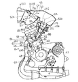
図2に示すように、エンジンEは、回転軸であるクランク軸40と、クランク軸40を支持するクランクケース42と、クランクケース42の上部に連結されてピストン43を収納するシリンダ44と、シリンダ44の上部に連結されたシリンダヘッド46と、シリンダヘッド46の上部を覆うシリンダヘッドカバー48とを備えている。クランク軸40は、エンジンEの幅方向、すなわち車幅方向に延びている。
As shown in FIG. 2, the engine E includes a
シリンダ44およびシリンダヘッド46の内部に、ウォータジャケット56が形成されている。ウォータジャケット56内の冷却水は、ラジエータ18(図1)で冷却される。エンジンの熱を奪って高温となった冷却水は、ラジエータ18へ導かれる。ラジエータ18を通過して温度の下がった冷却水は、ウォーターポンプ(図示せず)によりエンジンEのウォータジャケット56に供給される。
A
シリンダ44の内部に、燃焼室45が形成されている。燃焼室45の上部に吸気ポート60および排気ポート62が形成されている。吸気ポート60は排気ポート62よりも後方に配置されている。吸気ポート60に、これを開閉する吸気バルブ64が設けられている。排気ポート62に、これを開閉する排気バルブ66が設けられている。
A
シリンダヘッド46の後面に吸気入口46aが形成され、前面に排気出口46bが形成されている。シリンダ44の軸線AX1は、鉛直方向にクランクシャフト40から離れる方向に向かって排気ポート46b側に傾斜している。本実施形態では、シリンダ軸線AX1は上方に向かって前方に傾斜している。つまり、シリンダ44およびシリンダヘッド46は前方に傾斜して配置されている。
An
シリンダヘッド46の吸気入口46aの軸心AX2は、シリンダ軸線AX1に直交する方向にシリンダヘッド46から離れるに従って、シリンダ軸線AX1の方向にクランクシャフト40から離れるように延びている。本実施形態では、吸気入口46aの軸心AX2は、後方に向かって上方に傾斜して延びている。
The axial center AX2 of the
吸気入口46aと吸気ポート60とが内部吸気通路69により連通され、排気出口46bと排気ポート62とが内部排気通路71により連通されている。内部吸気通路69および内部排気通路71はシリンダヘッド46の内部に形成されている。吸気入口46aから内部吸気通路69および吸気ポート60を介して、空気または燃料と空気の混合気が燃焼室45に供給され、燃焼室45で燃焼される。つまり、内部吸気通路69は、燃焼室45に吸気を導入する吸気通路を構成し、吸気入口46aが内部吸気通路69(吸気通路)の入口を構成する。
The
一方、燃焼後の排気が、排気ポート62および内部排気通路71を介して排気出口46bから排出される。つまり、内部排気通路71は、燃焼室45から排気を導出する排気通路を構成し、排気出口46bが内部排気通路71(排気通路)の出口を構成する。排気ポート46aに排気管50が接続され、排気管50はエンジンEの下方で集合され、車体後方のマフラ(図示せず)に接続されている。
On the other hand, the exhaust gas after combustion is discharged from the
内部吸気通路69の曲率半径は、内部排気通路71の曲率半径よりも小さく設定されている。換言すれば、内部吸気通路69は、内部排気通路71に比べて、シリンダ軸線AX1に近づくように形成されている。また、内部吸気通路69の入口(吸気入口)46aは、シリンダ軸線AX1方向に関して、内部排気通路71の出口(排気出口)46bよりもクランクシャフト40から離れた位置に配置されている。本実施形態では、吸気入口46aは、排気出口46bよりも上方に配置されている。
The radius of curvature of the
シリンダヘッドカバー48の上方に、エアクリーナ36が配置されている。エアクリーナ36は、外郭を形成するクリーナケース52と、クリーナケース52に収納されたフィルタエレメント54とを有している。フィルタエレメント54は吸気を濾過する。つまり、クリーナケース52の内部空間におけるフィルタエレメント54よりも吸気流れ方向上流側にダーティ室53が形成され、下流側にクリーン室55が形成されている。
An
クリーナケース52に、ケース52内に吸気を導入するクリーナ入口52aと、ケース52内の吸気を排出するクリーナ出口52bとが形成されている。エアクリーナ36のクリーナ出口52bが、エンジンEのシリンダヘッド46の上方に配置されている。本実施形態では、エアタンク36のクリーン室55が、吸気入口46aの上方に配置されている。
A
クリーナ出口52bと吸気入口46aとの間に、スロットルボディ72が接続されている。スロットルボディ72は、吸気入口46a(吸気通路の入口)に接続される吸気管を構成する。スロットルボディ72の軸心は、吸気入口46aの軸心AX2と一致している。つまり、本実施形態のスロットルボディ72(吸気管)は、エンジンEに供給される空気が上方から下方に向かって流れるダウンドラフト構造である。
A
スロットルボディ72の内部の吸気通路に、吸気量を調整するスロットル弁74が設けられている。スロットルボディ72およびスロットル弁74は、気筒ごとに設けられている。スロットルボディ72に、上流側インジェクタ75が装着されている。上流側インジェクタ75は、スロットルボディ72の内部の吸気通路におけるスロットル弁74の吸気流れ方向下流側に燃料F1を噴射する。
A
上流側インジェクタ75は、スロットルボディ72(吸気管)よりもクランクシャフト40側に配置されている。本実施形態では、上流側インジェクタ75は、スロットルボディ72に取り付けられている。スロットル弁74および上流側インジェクタ75は、電子制御ユニット(図示せず)により制御される。
The
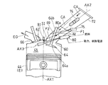
シリンダヘッド46の後面に、ポート噴射インジェクタ80が取り付けられている。ポート噴射インジェクタ80の出口80a(噴射口)は内部吸気通路69内に開口している。図3に示すように、ポート噴射インジェクタ80の噴射軸線AX3は、吸気バルブ64の開弁状態で、ポート噴射インジェクタ80の出口80aから吸気ポート60を通過して燃焼室45に至る。つまり、ポート噴射インジェクタ80は、吸気バルブ64の開弁状態で、吸気ポート60と吸気バルブ64の弁体64aとの隙間に向けて燃料を噴射する。
A
ポート噴射インジェクタ80は、燃焼室45の軸心寄り、つまり前記隙間におけるシリンダ軸線AX1寄りの部分S1に向けて燃料F2を噴射している。詳細には、吸気バルブ64の開状態で、ポート噴射インジェクタ80の噴射軸線AX3は、吸気バルブ64の弁軸64bよりもシリンダ軸線AX1側で吸気ポート60を通過している。
The
ポート噴射インジェクタ80は、エアクリーナ36(図2)の下方に配置されている。詳細には、ポート噴射インジェクタ80は、スロットルボディ72の下方に配置されている。換言すれば、ポート噴射インジェクタ80は、上方から下方に向かって吸気を燃焼室45内へ導入する吸気通路の下方に配置されている。ポート噴射インジェクタ80は、吸気通路に対して点火プラグ81の反対側に配置されている。図2に示すように、シリンダヘッド46におけるウォータジャケット56が形成された部位に隣接する位置に、ポート噴射インジェクタ80が取り付けられている。
The
ポート噴射インジェクタ80も、上流側インジェクタ75と同様に、吸気通路におけるクランクシャフト40側に配置されている。本実施形態では、ポート噴射インジェクタ80は、内部吸気通路69よりもクランクシャフト40側に配置されている。ポート噴射インジェクタ80は、吸気通路における上流側インジェクタ75の下流側に燃料F2を噴射する。
Similarly to the
本実施形態のエンジンEは、4バルブ式エンジンである。つまり、エンジンEの気筒85(シリンダ44およびシリンダヘッド46)ごとに、吸気バルブ64および排気バルブ66が2つ設けられている。各気筒85に、2つのポート噴射インジェクタ80が設けられている。つまり、燃焼室45ごとに、2つのポート噴射インジェクタ80から燃料F2が噴射されている。
The engine E of this embodiment is a 4-valve engine. That is, two
図4に示すように、シリンダヘッド46には、気筒85(燃焼室45)ごとに、内部吸気通路69が形成されている。図4も、1つの気筒85のみを示している。各内部吸気通路69は、上流部分69aと、上流部分69aから分岐する2つの下流部分69bとを有している。上流部分69aの上流端は、吸気入口46aに連通している。下流部分69bの下流端は吸気ポート60に連通している。また、各内部吸気通路69にスロットルボディ72が接続され、各スロットルボディ72にスロットルバルブ74が内蔵されている。
As shown in FIG. 4, an
各内部吸気通路69に、2つのポート噴射インジェクタ80が設けられている。一方のポート噴射インジェクタ80は、内部吸気通路69の一方の下流部分69bを介して吸気ポート60に燃料F2を噴射する。他方のポート噴射インジェクタ80は、他方の下流部分69bを介して吸気ポート60に燃料F2を噴射する。
In each
つぎに、本実施形態のエンジンの吸気系の作用について説明する。図1のエンジンEが始動して自動二輪車が走行すると、走行風Aが空気取入口30からラムダクトユニット34に導入される。走行風Aは、ラムダクトユニット34から吸入ダクト部32を通過して、図2に示すエアクリーナ36に導入される。走行風Aは、エアクリーナ36内でフィルタエレメント54により濾過され、清浄空気CAとなる。
Next, the operation of the intake system of the engine of this embodiment will be described. When the engine E of FIG. 1 is started and the motorcycle travels, the traveling wind A is introduced from the air intake 30 into the
クリーン室55内の清浄空気CAは、図3に示すスロットルボディ72を介してエンジンEの吸気入口46aに導入される。このとき、スロットルボディ72内部で、スロットル弁74により空気量が調整されるとともに、スロットル弁74の下流側で上流側インジェクタ75から清浄空気CAに燃料F1が噴霧され混合気Mが生成される。このとき、スロットル弁74で絞られて流速が増した清浄空気CAによって、上流側インジェクタ75から噴射された燃料F1(混合気M)が円滑に流れる。
The clean air CA in the clean chamber 55 is introduced into the
混合気Mは、吸気入口46aからエンジンEの内部に導入され、内部吸気通路69を通過して吸気ポート60から燃焼室45に導入される。また、ポート噴射インジェクタ80から燃焼室45内に燃料F2が噴射されている。吸気ポート60から導入された混合気Mは、ポート噴射インジェクタ80から燃焼室45に噴霧された燃料F2と共に燃焼室45内で燃焼される。燃焼後の排気ガスEGは、排気ポート62を介して燃焼室45の外部に排出される。
The air-fuel mixture M is introduced into the engine E from the
なお、上記実施形態では、上流側インジェクタ75が設けられているが、上流側インジェクタ75は省略できる。上流側インジェクタ75を省略した場合、図3に二点鎖線で示すように、吸気入口46aから内部吸気通路69に清浄空気CAが導入される。清浄空気CAは、ポート噴射インジェクタ80から噴射された燃料F2とともに吸気ポート60から燃焼室45に導入される。
In the above embodiment, the
上記構成によれば、吸気ポート60の開状態でポート噴射インジェクタ80から燃料F2が噴射されることで、液体燃料が燃焼室45内に噴霧される。この燃料が燃焼室45内で気化することで、燃焼室45内の温度上昇が抑制される。また、ポート噴射インジェクタ80の噴射軸心AX3が吸気ポート60を通過して燃焼室45に至るように配置されているので、燃料の大部分が吸気通路壁に衝突することなく燃焼室45に導入され、燃焼室45内の熱を奪う。
According to the above configuration, the fuel F2 is injected from the
これらにより、エンジンEの高圧縮比化を図ることができる。その結果、エンジンEの燃焼効率の向上が期待され、エンジンEの出力向上および燃費向上を図ることができる。また、ポート噴射インジェクタ80が内部吸気通路69よりもクランクシャフト40側に配置されているので、内部吸気通路69をシリンダ軸線AX1に近づけて形成し易い。これにより、燃焼室45に向かう内部吸気通路69の形状を直線に近づけることができ、流路抵抗を低下させることができる。その結果、エンジン出力の向上を図ることができる。
As a result, the compression ratio of the engine E can be increased. As a result, the combustion efficiency of the engine E is expected to be improved, and the output of the engine E and the fuel efficiency can be improved. Further, since the
また、ポート噴射インジェクタ80の燃料配管、制御ケーブル、動力ケーブルも、内部吸気通路69よりもクランクシャフト40側に配置することができる。これにより、内部吸気通路69をシリンダ軸線AX1に近づけて配置できる。その結果、ポート噴射インジェクタ80からの燃料F2を遠くまで噴射する必要がなく、燃料の微粒化を図り易い。
Further, the fuel piping, the control cable, and the power cable of the
さらに、吸気ポート60の開状態でポート噴射インジェクタ80から燃料F2が噴射されるから、吸気通路壁への燃料の付着が抑制されるので、直噴エンジンのような高出力/高トルク、低燃費および排ガス改善を期待できる。しかも、噴射口80aが燃焼室45ではなく、内部吸気通路69内(ポート内)に配置されているので、高圧ポンプが不要である。したがって、直噴エンジンに比べて構成が簡単である。
Further, since the fuel F2 is injected from the
内部吸気通路69の入口(吸気入口)46aの軸心AX2は、後方に向かって上方に延びている。このように、内部吸気通路69がクランクシャフト40から離れる上方向に延びているので、内部吸気通路69よりもクランクシャフト40側の下方にポート噴射インジェクタ80を配置し易い。つまり、ポート噴射インジェクタ80を吸気バルブ64の近くに配置し易い。これにより、気化前の燃料F2を燃焼室45に届けることができる。
An axis AX2 of the inlet (intake inlet) 46a of the
内部吸気通路71の曲率半径が、内部排気通路71の曲率半径よりも大きく設定され、内部吸気通路69の入口46aが内部排気通路71の出口46bよりも上方に配置されている。これにより、内部吸気通路69をシリンダ軸線AX1に近づけて形成し易くなるので、内部吸気通路69のクランクシャフト40側にポート噴射インジェクタ80をより一層配置し易い。
The radius of curvature of the
シリンダヘッド46におけるポート噴射インジェクタ80が取り付けられる位置に隣接する部位に、ウォータジャケット56が形成されている。これにより、ポート噴射インジェクタ80の周囲が冷却されるので、ポート噴射インジェクタ80から噴射される燃料F2の温度が上昇するのを抑制できる。その結果、気化前の燃料を燃焼室45内に噴霧し易い。
A
吸気バルブ64の開状態で、ポート噴射インジェクタ80の噴射軸線AX3は、吸気バルブ64の弁軸64bよりもシリンダ軸線AX1側で吸気ポート60を通過している。これにより、ポート噴射インジェクタ80からの燃料を燃焼室45の上部に導入することができる。したがって、燃焼室45の上部に導入される吸気との混合が促進されて、燃焼効率が向上する。
In the open state of the
図4に示すように、各気筒85に2つのポート噴射インジェクタ80が設けられ、各燃焼室45に2つのポート噴射インジェクタ80,80から燃料が噴射されている。したがって、1つのポート噴射インジェクタ80から噴射される燃料の流量が半分になる。その結果、微粒化を実現でき、混合気の均質性が向上する。これにより、燃焼室45内での燃焼が安定するうえに、THC(全炭化水素)を低減できる。また、ポート噴射インジェクタ80ごとに噴射の特性を代えることで、燃料噴射の多様性を実現できる。
As shown in FIG. 4, each
図2に示すスロットルボディ72におけるクランクシャフト40側の部分に、上流側インジェクタ75が取り付けられている。2つのインジェクタ75,80を設けることにより、噴射の多様性を図ることができる。また、2つのインジェクタ75,80がクランクシャフト40側にあるので、燃料配管を配置し易い。
An
シリンダヘッド46にポート噴射インジェクタ80が配置されているので、出口80a(噴射口)から燃焼室45までの距離を短くすることができる。これにより、燃焼室45に燃料F2を供給し易くできる。スロットルボディ72にポート噴射インジェクタ80を固定する場合、スロットルボディ72の取付誤差により、吸気ポート60に対するポート噴射インジェクタ80の噴射軸線AX3の位置にずれが生じる可能性がある。上記構成では、シリンダヘッド46にポート噴射インジェクタ80が固定されているので、吸気ポート60に対する噴射軸線AX3のずれを小さくすることができる。
Since the
開弁状態の吸気バルブ64の弁体64aよりも上方、すなわちクランクシャフト40と反対側を通過するように、噴射軸線AX3が設定されている。これにより、点火プラグ81の近傍に燃料F2を噴射し易い。ポート噴射インジェクタ80は、吸気通路に対して、スロットル弁74の駆動装置と反対側に配置されている。これにより、ポート噴射インジェクタ80とスロットル弁74の駆動装置との干渉を防ぐことができる。
The injection axis AX3 is set so as to pass above the
ポート噴射インジェクタ80の噴射軸線AX3は、吸気バルブ64の弁軸64bを通過するように配置されてもよく、弁軸64bに干渉しないように配置されてもよい。また、噴射軸線AX3は、吸気バルブ64の弁体64aに干渉しないように配置されてもよい。噴射軸線AX3を弁体64aに干渉しないように配置することで、弁体64aに燃料F2が衝突することが防がれて、燃焼室45に効果的に燃料F2を供給できる。噴射軸線AX3を弁体64aに対してシリンダ軸線A1寄りにずらすと、上死点にピストンが達した場合の狭い燃焼室45に燃料F2を噴射できる。噴射軸線AX3を弁体64aに対してシリンダ軸線A1と反対側にずらすと、シリンダ軸線A1回りの吸気の旋回流に沿って燃料を攪拌させ易い。
The injection axis AX3 of the
内部吸気通路69は、吸気入口46aから吸気ポート60まで湾曲しながら延びている。ポート噴射インジェクタ80の燃料F2は、吸気バルブ64の弁体64aに対して、湾曲の径方向外側を通過して燃焼室45に噴射されている。内部吸気通路69における湾曲の外側は、遠心力により流速が大きくなる。このような流速が大きくなる領域に燃料F2が噴射されることで、燃料が燃焼室45に導かれ易くなる。
The
図5に第2実施形態に係るエンジンの気筒を示す。図5は、代表して1つの気筒85のみを示している。図5に示すように、第2実施形態では、内部吸気通路69ごとにポート噴射インジェクタ80が1つ設けられ、ポート噴射インジェクタ80の出口80a(噴射口)が2つ設けられている。2つの噴射口80aから対応する吸気ポート60に向けて燃料F2が噴射されている。第2実施形態においても、上述の第1実施形態と同様の効果を奏する。
FIG. 5 shows a cylinder of an engine according to the second embodiment. FIG. 5 shows only one
上記実施形態では、自然吸気のエンジンについて説明したが、本発明は過給エンジンにも適用できる。過給エンジンは、エアクリーナ36の下流側でスロットルボディ72の上流側に過給機と吸気チャンバとが設けられる。過給エンジンの場合、吸気温度が高くなりやすいので、本発明のポート噴射インジェクタ80による燃焼室45内の温度の抑制がより効果的である。過給エンジンの場合も、上流側インジェクタ75を省略してもよい。
In the above embodiment, a naturally aspirated engine has been described, but the present invention can also be applied to a supercharged engine. The supercharged engine is provided with a supercharger and an intake chamber on the downstream side of the
また、上記実施形態では、吸気通路における吸入ダクト部32は、エンジンEの上方の空間を通過しているが、吸気通路がエンジンEのシリンダ44またはシリンダヘッド46の側方の空間を通過してもよい。上記実施形態のエンジンEは4気筒であったが、単気筒であってもよく、4気筒以外であってもよい。また、スロットル弁74は電動でなくてもよい。
In the above embodiment, the
本発明は、以上の実施形態に限定されるものでなく、本発明の要旨を逸脱しない範囲内で、種々の追加、変更または削除が可能である。例えば、上記実施形態では、4バルブ式のエンジンEについて説明したが、本発明は2バルブ式のエンジンEにも適用できる。また、上記実施形態では、本発明のエンジンEを自動二輪車に適用した例について説明したが、本発明のエンジンEは、三輪車、四輪バギーのような自動二輪車以外の鞍乗型車両にも適用可能である。したがって、そのようなものも本発明の範囲内に含まれる。 The present invention is not limited to the above-described embodiments, and various additions, modifications, or deletions can be made without departing from the gist of the present invention. For example, in the above embodiment, the four-valve engine E has been described, but the present invention can also be applied to a two-valve engine E. Moreover, although the said embodiment demonstrated the example which applied the engine E of this invention to the motorcycle, the engine E of this invention is applied also to a straddle-type vehicle other than motorcycles, such as a tricycle and a four-wheel buggy. Is possible. Therefore, such a thing is also included in the scope of the present invention.
40 クランクシャフト
44 シリンダ
45 燃焼室
46 シリンダヘッド
46a 吸気入口(吸気通路の入口)
46b 排気出口(排気通路の出口)
56 ウォータジャケット
60 吸気ポート
64 吸気バルブ
64b 吸気バルブの弁軸
69 内部吸気通路(吸気通路)
71 内部排気通路(排気通路)
72 スロットルボディ(吸気管)
75 上流側インジェクタ
80 ポート噴射インジェクタ
80a インジェクタの出口
AX1 シリンダ軸線
AX2 吸気通路の入口の軸心
AX3 インジェクタの噴射軸線
E エンジン
40
46b Exhaust outlet (exhaust passage outlet)
56
71 Internal exhaust passage (exhaust passage)
72 Throttle body (intake pipe)
75
Claims (8)
前記燃焼室に吸気を導入する吸気通路が形成されたシリンダヘッドと、
前記吸気通路における前記燃焼室に開口する吸気ポートを開閉する吸気バルブと、
前記吸気通路よりもクランクシャフト側に配置された燃料のポート噴射インジェクタと、を備え、
前記ポート噴射インジェクタは、その噴射軸線が前記ポート噴射インジェクタの出口から前記吸気ポートを通過して前記燃焼室に至るように配置されているエンジン。 A cylinder in which a combustion chamber is formed;
A cylinder head formed with an intake passage for introducing intake air into the combustion chamber;
An intake valve that opens and closes an intake port that opens to the combustion chamber in the intake passage;
A fuel port injection injector disposed closer to the crankshaft than the intake passage,
The port injection injector is an engine arranged such that an injection axis thereof passes from the outlet of the port injection injector through the intake port to the combustion chamber.
前記吸気通路の曲率半径が、前記排気通路の曲率半径よりも大きく設定されているエンジン。 The engine according to claim 1 or 2, wherein an exhaust passage for leading exhaust gas from the combustion chamber is formed in the cylinder head.
An engine in which a radius of curvature of the intake passage is set larger than a radius of curvature of the exhaust passage.
前記シリンダヘッドにおける前記ポート噴射インジェクタが取り付けられる位置に隣接する部位に、ウォータジャケットが形成されているエンジン。 The engine according to any one of claims 1 to 4, wherein the port injector is attached to the cylinder head,
An engine in which a water jacket is formed in a portion of the cylinder head adjacent to the position where the port injection injector is attached.
The engine according to any one of claims 1 to 7, further comprising an intake pipe connected to an inlet of the intake passage, and a fuel disposed inside the intake pipe, disposed closer to a crankshaft than the intake pipe. And an upstream injector for injecting fuel.
Priority Applications (2)
| Application Number | Priority Date | Filing Date | Title |
|---|---|---|---|
| JP2018109284A JP2019210893A (en) | 2018-06-07 | 2018-06-07 | engine |
| DE102019114283.0A DE102019114283A1 (en) | 2018-06-07 | 2019-05-28 | piston engine |
Applications Claiming Priority (1)
| Application Number | Priority Date | Filing Date | Title |
|---|---|---|---|
| JP2018109284A JP2019210893A (en) | 2018-06-07 | 2018-06-07 | engine |
Publications (2)
| Publication Number | Publication Date |
|---|---|
| JP2019210893A true JP2019210893A (en) | 2019-12-12 |
| JP2019210893A5 JP2019210893A5 (en) | 2021-03-18 |
Family
ID=68651942
Family Applications (1)
| Application Number | Title | Priority Date | Filing Date |
|---|---|---|---|
| JP2018109284A Pending JP2019210893A (en) | 2018-06-07 | 2018-06-07 | engine |
Country Status (2)
| Country | Link |
|---|---|
| JP (1) | JP2019210893A (en) |
| DE (1) | DE102019114283A1 (en) |
Families Citing this family (1)
| Publication number | Priority date | Publication date | Assignee | Title |
|---|---|---|---|---|
| JP2024051787A (en) * | 2022-09-30 | 2024-04-11 | 本田技研工業株式会社 | Fuel supply system |
Citations (8)
| Publication number | Priority date | Publication date | Assignee | Title |
|---|---|---|---|---|
| JPS62247173A (en) * | 1986-04-19 | 1987-10-28 | Mazda Motor Corp | Intake device of engine |
| JPH06159201A (en) * | 1992-11-27 | 1994-06-07 | Mazda Motor Corp | Fuel injection device of engine |
| JP2002048035A (en) * | 2000-08-02 | 2002-02-15 | Yamaha Motor Co Ltd | Cylinder fuel injection engine with supercharger |
| JP2004353463A (en) * | 2003-05-27 | 2004-12-16 | Toyota Motor Corp | Control device for internal combustion engine |
| JP2009103137A (en) * | 2003-11-07 | 2009-05-14 | Yamaha Motor Co Ltd | Fuel feeding device and vehicle provided with the same |
| US20140000559A1 (en) * | 2010-12-27 | 2014-01-02 | Andreas Gutscher | Injection device, an internal combustion engine, and a method for operating an injection device for gasoline and cng |
| JP2014065467A (en) * | 2012-09-27 | 2014-04-17 | Honda Motor Co Ltd | Saddle riding type vehicle |
| JP2015169186A (en) * | 2014-03-11 | 2015-09-28 | 本田技研工業株式会社 | Saddle riding type vehicle internal combustion engine equipped with supercharger |
Family Cites Families (1)
| Publication number | Priority date | Publication date | Assignee | Title |
|---|---|---|---|---|
| JPH05340326A (en) | 1992-06-08 | 1993-12-21 | Nissan Motor Co Ltd | Fuel supply device for internal combustion engine |
-
2018
- 2018-06-07 JP JP2018109284A patent/JP2019210893A/en active Pending
-
2019
- 2019-05-28 DE DE102019114283.0A patent/DE102019114283A1/en active Pending
Patent Citations (8)
| Publication number | Priority date | Publication date | Assignee | Title |
|---|---|---|---|---|
| JPS62247173A (en) * | 1986-04-19 | 1987-10-28 | Mazda Motor Corp | Intake device of engine |
| JPH06159201A (en) * | 1992-11-27 | 1994-06-07 | Mazda Motor Corp | Fuel injection device of engine |
| JP2002048035A (en) * | 2000-08-02 | 2002-02-15 | Yamaha Motor Co Ltd | Cylinder fuel injection engine with supercharger |
| JP2004353463A (en) * | 2003-05-27 | 2004-12-16 | Toyota Motor Corp | Control device for internal combustion engine |
| JP2009103137A (en) * | 2003-11-07 | 2009-05-14 | Yamaha Motor Co Ltd | Fuel feeding device and vehicle provided with the same |
| US20140000559A1 (en) * | 2010-12-27 | 2014-01-02 | Andreas Gutscher | Injection device, an internal combustion engine, and a method for operating an injection device for gasoline and cng |
| JP2014065467A (en) * | 2012-09-27 | 2014-04-17 | Honda Motor Co Ltd | Saddle riding type vehicle |
| JP2015169186A (en) * | 2014-03-11 | 2015-09-28 | 本田技研工業株式会社 | Saddle riding type vehicle internal combustion engine equipped with supercharger |
Also Published As
| Publication number | Publication date |
|---|---|
| DE102019114283A1 (en) | 2019-12-12 |
Similar Documents
| Publication | Publication Date | Title |
|---|---|---|
| US9284927B2 (en) | Motorcycle with turbocharger | |
| US7743741B2 (en) | Fuel injection engine and motorcycle comprising fuel injection engine | |
| US8083558B2 (en) | Outboard motor | |
| JP5293550B2 (en) | Multi-cylinder engine intake system | |
| JP6107381B2 (en) | Fuel injection device for motorcycle engine | |
| JP4853481B2 (en) | Intake device for internal combustion engine | |
| US9745916B2 (en) | Internal combustion engine | |
| JP7358824B2 (en) | engine intake system | |
| JP2010223211A (en) | Forced air-cooled engine unit for vehicle and motorcycle | |
| JP5393375B2 (en) | Internal combustion engine | |
| JP2003129921A (en) | Four-cycle engine for outboard engine | |
| JP2019210893A (en) | engine | |
| JP2020079597A (en) | Internal combustion engine | |
| JP2008208819A (en) | Internal combustion engine provided with variable intake device | |
| US11629634B2 (en) | Straddled vehicle | |
| JP3154878U (en) | engine | |
| JP6277661B2 (en) | Motorcycle with turbocharger | |
| JP6302926B2 (en) | engine | |
| US6691673B2 (en) | Fuel supply device for outboard motor | |
| JP2006077774A (en) | Outboard motor | |
| US20070240410A1 (en) | Multiple-cylinder engine for outboard motor | |
| JP7376384B2 (en) | Internal combustion engine with exhaust turbocharger | |
| JP5345033B2 (en) | Internal combustion engine | |
| WO2020217656A1 (en) | Saddle-type vehicle | |
| JP2019210892A (en) | engine |
Legal Events
| Date | Code | Title | Description |
|---|---|---|---|
| A521 | Request for written amendment filed |
Free format text: JAPANESE INTERMEDIATE CODE: A523 Effective date: 20210204 |
|
| A621 | Written request for application examination |
Free format text: JAPANESE INTERMEDIATE CODE: A621 Effective date: 20210204 |
|
| A977 | Report on retrieval |
Free format text: JAPANESE INTERMEDIATE CODE: A971007 Effective date: 20220119 |
|
| A711 | Notification of change in applicant |
Free format text: JAPANESE INTERMEDIATE CODE: A712 Effective date: 20220124 |
|
| A131 | Notification of reasons for refusal |
Free format text: JAPANESE INTERMEDIATE CODE: A131 Effective date: 20220308 |
|
| A521 | Request for written amendment filed |
Free format text: JAPANESE INTERMEDIATE CODE: A523 Effective date: 20220421 |
|
| A131 | Notification of reasons for refusal |
Free format text: JAPANESE INTERMEDIATE CODE: A131 Effective date: 20220823 |
|
| A521 | Request for written amendment filed |
Free format text: JAPANESE INTERMEDIATE CODE: A523 Effective date: 20221011 |
|
| A02 | Decision of refusal |
Free format text: JAPANESE INTERMEDIATE CODE: A02 Effective date: 20230131 |