JP5035138B2 - Damping device for turbomachine stator - Google Patents
Damping device for turbomachine stator Download PDFInfo
- Publication number
- JP5035138B2 JP5035138B2 JP2008165446A JP2008165446A JP5035138B2 JP 5035138 B2 JP5035138 B2 JP 5035138B2 JP 2008165446 A JP2008165446 A JP 2008165446A JP 2008165446 A JP2008165446 A JP 2008165446A JP 5035138 B2 JP5035138 B2 JP 5035138B2
- Authority
- JP
- Japan
- Prior art keywords
- layer
- stator
- stator according
- layers
- rigid
- Prior art date
- Legal status (The legal status is an assumption and is not a legal conclusion. Google has not performed a legal analysis and makes no representation as to the accuracy of the status listed.)
- Active
Links
Images


Classifications
-
- F—MECHANICAL ENGINEERING; LIGHTING; HEATING; WEAPONS; BLASTING
- F16—ENGINEERING ELEMENTS AND UNITS; GENERAL MEASURES FOR PRODUCING AND MAINTAINING EFFECTIVE FUNCTIONING OF MACHINES OR INSTALLATIONS; THERMAL INSULATION IN GENERAL
- F16F—SPRINGS; SHOCK-ABSORBERS; MEANS FOR DAMPING VIBRATION
- F16F9/00—Springs, vibration-dampers, shock-absorbers, or similarly-constructed movement-dampers using a fluid or the equivalent as damping medium
- F16F9/30—Springs, vibration-dampers, shock-absorbers, or similarly-constructed movement-dampers using a fluid or the equivalent as damping medium with solid or semi-solid material, e.g. pasty masses, as damping medium
- F16F9/306—Springs, vibration-dampers, shock-absorbers, or similarly-constructed movement-dampers using a fluid or the equivalent as damping medium with solid or semi-solid material, e.g. pasty masses, as damping medium of the constrained layer type, i.e. comprising one or more constrained viscoelastic layers
-
- F—MECHANICAL ENGINEERING; LIGHTING; HEATING; WEAPONS; BLASTING
- F01—MACHINES OR ENGINES IN GENERAL; ENGINE PLANTS IN GENERAL; STEAM ENGINES
- F01D—NON-POSITIVE DISPLACEMENT MACHINES OR ENGINES, e.g. STEAM TURBINES
- F01D25/00—Component parts, details, or accessories, not provided for in, or of interest apart from, other groups
- F01D25/04—Antivibration arrangements
-
- F—MECHANICAL ENGINEERING; LIGHTING; HEATING; WEAPONS; BLASTING
- F01—MACHINES OR ENGINES IN GENERAL; ENGINE PLANTS IN GENERAL; STEAM ENGINES
- F01D—NON-POSITIVE DISPLACEMENT MACHINES OR ENGINES, e.g. STEAM TURBINES
- F01D25/00—Component parts, details, or accessories, not provided for in, or of interest apart from, other groups
- F01D25/24—Casings; Casing parts, e.g. diaphragms, casing fastenings
- F01D25/246—Fastening of diaphragms or stator-rings
-
- F—MECHANICAL ENGINEERING; LIGHTING; HEATING; WEAPONS; BLASTING
- F01—MACHINES OR ENGINES IN GENERAL; ENGINE PLANTS IN GENERAL; STEAM ENGINES
- F01D—NON-POSITIVE DISPLACEMENT MACHINES OR ENGINES, e.g. STEAM TURBINES
- F01D9/00—Stators
- F01D9/02—Nozzles; Nozzle boxes; Stator blades; Guide conduits, e.g. individual nozzles
- F01D9/04—Nozzles; Nozzle boxes; Stator blades; Guide conduits, e.g. individual nozzles forming ring or sector
- F01D9/041—Nozzles; Nozzle boxes; Stator blades; Guide conduits, e.g. individual nozzles forming ring or sector using blades
-
- F—MECHANICAL ENGINEERING; LIGHTING; HEATING; WEAPONS; BLASTING
- F05—INDEXING SCHEMES RELATING TO ENGINES OR PUMPS IN VARIOUS SUBCLASSES OF CLASSES F01-F04
- F05D—INDEXING SCHEME FOR ASPECTS RELATING TO NON-POSITIVE-DISPLACEMENT MACHINES OR ENGINES, GAS-TURBINES OR JET-PROPULSION PLANTS
- F05D2260/00—Function
- F05D2260/96—Preventing, counteracting or reducing vibration or noise
-
- Y—GENERAL TAGGING OF NEW TECHNOLOGICAL DEVELOPMENTS; GENERAL TAGGING OF CROSS-SECTIONAL TECHNOLOGIES SPANNING OVER SEVERAL SECTIONS OF THE IPC; TECHNICAL SUBJECTS COVERED BY FORMER USPC CROSS-REFERENCE ART COLLECTIONS [XRACs] AND DIGESTS
- Y02—TECHNOLOGIES OR APPLICATIONS FOR MITIGATION OR ADAPTATION AGAINST CLIMATE CHANGE
- Y02T—CLIMATE CHANGE MITIGATION TECHNOLOGIES RELATED TO TRANSPORTATION
- Y02T50/00—Aeronautics or air transport
- Y02T50/60—Efficient propulsion technologies, e.g. for aircraft
Description
本発明は、ターボ機械の分野に関し、特にはターボジェットまたはターボプロップなどのガスタービンエンジンの分野に関し、ステータ部品のための振動減衰装置を目的として有する。 The present invention relates to the field of turbomachines, in particular to the field of gas turbine engines such as turbojets or turboprops, with the object of vibration damping devices for stator parts.
航空機用のターボ機械は、固定の羽根付きインペラ(圧縮機またはタービンのどちらに関するかに応じて、ステータ羽根リングまたは上流側ガス流案内羽根部材を構成する)と相互作用する複数の可動の羽根付きインペラ(すなわち、外周に可動のブレードがガス流中に取り付けられている回転ディスク)からなる。タービンは、それぞれがいくつかの羽根を備えるリングセクタの形態のアセンブリ、または例えば可変のピッチを有する単独の羽根の形態のアセンブリからなり得る。これらの構成要素は、寸法に関して、ガス流のためのシールをもたらしつつ、温度および空気力学的な負荷に対する機械的な耐力という要請を満足しなければならないため、特に繊細な部品である。これらの状況のすべてが、これらの構造体に静的な荷重が加わること、および寿命の要請ゆえに、それらに加わる振動の振幅を小さく保たなければならないということを意味する。 Aircraft turbomachines are equipped with a plurality of movable vanes that interact with a fixed vaned impeller (which constitutes a stator vane ring or an upstream gas flow guide vane member, depending on whether it is a compressor or turbine) It consists of an impeller (i.e. a rotating disk with movable blades attached to its periphery in the gas stream). The turbine may consist of an assembly in the form of a ring sector, each comprising several blades, or an assembly in the form of a single blade, for example with a variable pitch. These components are particularly sensitive parts because they must meet the requirements of mechanical resistance to temperature and aerodynamic loads while providing a seal for gas flow in terms of dimensions. All of these situations mean that these structures are subject to static loads and that the amplitude of vibration applied to them must be kept small because of life requirements.
ターボ機械の設計およびチューニングは、いくつかの規律の協調を必要とするため、寸法決定のプロセスは反復的である。振動に関する寸法決定は、動作範囲に重大なモードが存在しないようにするために行われる。アセンブリが、設計サイクルの終わりにおいて、エンジンテストで振動の振幅を測定することによって検証される。高いレベルが、同期または非同期の強制応答あるいは不安定に起因して現われることがある。その結果、ステータ羽根リングまたは上流側案内羽根部材を再設計しなければならず、これは、きわめて時間がかかり高価につくプロセスである。 Since turbomachine design and tuning requires the coordination of several disciplines, the sizing process is iterative. Sizing for vibrations is done so that there are no critical modes in the operating range. The assembly is verified at the end of the design cycle by measuring vibration amplitude with engine tests. High levels may appear due to synchronous or asynchronous forced responses or instability. As a result, the stator vane ring or upstream guide vane member must be redesigned, which is a very time consuming and expensive process.
したがって、製造上の目的は、寸法決定のサイクルにおいて、設計において可能な限り早期に必要とされる是正手段を講じることができるよう、構造体の振動応答のレベルを可能な限り早期に予測することにある。これらの問題の中でも、機械的な減衰が、設計者にとって重要な問題である。 Therefore, the manufacturing objective is to predict the level of vibration response of the structure as early as possible in the dimensioning cycle so that the corrective measures required as early as possible in the design can be taken. It is in. Among these issues, mechanical damping is an important issue for designers.
振動疲労に対するこれらの部品の頑丈さを保証するために、1つの解決策は、エネルギーの散逸の源として機能する特定の装置を構造体に負荷することからなる。例えば、圧縮機の可動のインペラのブレードの減衰手段が、EP1253290によって知られている。この減衰手段は、粘弾性材料の層および応力層を備える。ブレードの外形は、ガス流の流れの中に位置するため、この文献において提案されている解決策は、ブレードの外形に切り欠きをくり抜き、減衰手段を収容するようにしている。したがって、流れに接するブレードの外形の表面が、不規則を呈しておらず、ガス流が乱されることがない。このような構成は、ブレードの薄さゆえに、厄介な機械加工を必要とする。さらに、1つの同じインペラの種々のブレードの間に不釣り合いを持ち込む恐れがあり、アンバランスにつながる。
本発明の目的は、動的な減衰をもたらすことによって、同期または非同期の応力のもとでの構造体の動的応答(空気力学的な起源のものであるか否かにかかわらず)を減衰させることにある。 The purpose of the present invention is to damp the dynamic response of a structure (whether of aerodynamic origin or not) under synchronous or asynchronous stress by providing dynamic damping There is to make it.
同心である第1の内側リングおよび第2の外側リングの間に複数の羽根を放射状に配置して備え、第2のリングが円柱形の外表面部分を有する本発明によるステータ羽根リングまたは上流側案内羽根部材を形成するターボ機械のステータは、上記外表面部分に、少なくとも1つの振動減衰積層体が取り付けられており、積層体が、粘弾性材料からなる少なくとも1つの層を上記表面部分および剛性材料からなる1つのカウンタ層に接触させて備える点で注目に値する。 A stator vane ring or upstream according to the present invention comprising a plurality of vanes arranged radially between concentric first inner ring and second outer ring, wherein the second ring has a cylindrical outer surface portion In the turbomachine stator forming the guide vane member, at least one vibration damping laminate is attached to the outer surface portion, and the laminate has at least one layer made of a viscoelastic material as the surface portion and the rigidity. It is noteworthy in that it is provided in contact with one counter layer made of material.
本発明の独創性は、粘弾性材料の少なくとも1つの層からなる積層体を少なくとも1つの応力層とともに使用し、この積層体を構造体へと貼り付けて、該当部分の振動エネルギーを散逸させることにある。 The originality of the present invention is that a laminate composed of at least one layer of viscoelastic material is used together with at least one stress layer, and this laminate is attached to a structure to dissipate vibration energy of the corresponding part. It is in.
振動エネルギーの散逸は、動的な応力のもとで変形する構造体と慣性によって引っ張られる応力層との間での粘弾性材料のせん断変形によって得られる。これらの積層体が、セクタであるステータ羽根リングまたは上流側案内羽根部材の外側へと、外冠(outer crown)において、貼り付けまたは取り付けされ、該当の部品の振動モードを直接的に減衰させる。 The dissipation of vibrational energy is obtained by shear deformation of the viscoelastic material between a structure that deforms under dynamic stress and a stress layer that is pulled by inertia. These laminates are affixed or attached to the outside of the sector stator ring or upstream guide vane member at the outer crown to directly dampen the vibration mode of the part in question.
本発明は、金属部品の構造減衰を大きくし、設計において直面される振動の問題を解決することを可能にする。この結果として、最終的に、関連の開発およびチューニングの時間が短縮され、したがってコストが削減される。 The present invention makes it possible to increase the structural damping of metal parts and to solve the vibration problems encountered in the design. As a result, the associated development and tuning time is ultimately reduced, thus reducing costs.
また、交互する荷重および間接的な重量の増加に対する耐久性の提供を満足することによって区切られる従来の設計の分野の拡大を可能にする。 It also allows an expansion of the field of conventional design delimited by satisfying the provision of durability against alternating loads and indirect weight increases.
本発明は、エンジンの高調波、非同期または音響の励起、空力弾性の不安定、またはロータ−ステータの接触による衝撃と交差する動的な荷重の種類にかかわらず適用可能である。 The present invention is applicable regardless of the type of dynamic load that intersects with engine harmonics, asynchronous or acoustic excitation, aeroelastic instability, or impact due to rotor-stator contact.
種々の実施形態によれば、
積層体が、軸方向または周方向において、上記外表面部分を部分的に覆っている。
ステータ羽根リングまたは上流側案内羽根部材が、外表面部分を覆って周方向に分布した複数の積層体を備える。
層が一体に接続されている。
層が、接着によって一体に接続されている。
カウンタ層が、機械的な取り付け部材を備える。
機械的な取り付け部材が、カウンタ層をステータ羽根リングまたは上流側案内羽根部材へと接続している。
機械的な取り付け部材が、粘弾性層を上記外表面部分に押し付けられた状態に保っている。
積層体が、粘弾性層および交互の剛性層の積み重ねからなる。
粘弾性材料の特性が、或る層とその他の層とで異なっている。
粘弾性材料の特性が、或る層とその他の層とで同じである。
剛性材料の特性が、或る剛性層とその他の剛性層とで異なっている。
剛性材料の特性が、或る剛性層とその他の剛性層とで同じである。
According to various embodiments,
The laminate partially covers the outer surface portion in the axial direction or the circumferential direction.
The stator blade ring or the upstream guide blade member includes a plurality of laminated bodies distributed in the circumferential direction covering the outer surface portion.
The layers are connected together.
The layers are connected together by gluing.
The counter layer comprises a mechanical attachment member.
A mechanical mounting member connects the counter layer to the stator vane ring or upstream guide vane member.
A mechanical attachment member keeps the viscoelastic layer pressed against the outer surface portion.
The laminate consists of a stack of viscoelastic layers and alternating rigid layers.
The properties of viscoelastic materials differ between certain layers and other layers.
The properties of the viscoelastic material are the same in one layer and the other.
The properties of the rigid material differ between certain rigid layers and other rigid layers.
The properties of the rigid material are the same in certain rigid layers and other rigid layers.
さらに、本発明は、このようなステータ羽根リングまたは上流側案内羽根部材を少なくとも1つ備えるターボ機械に関する。タービン段の上流側案内羽根部材または圧縮段のステータ羽根リングであってよい。 Furthermore, the present invention relates to a turbomachine including at least one such stator blade ring or upstream guide blade member. It may be a turbine stage upstream guide vane member or a compression stage stator vane ring.
他の特徴および利点が、添付の図面を参照する本発明の種々の実施形態についての以下の説明から、明らかになるであろう。 Other features and advantages will become apparent from the following description of various embodiments of the invention with reference to the accompanying drawings.
図1を参照すると、ターボファンツインスプールターボジェット1の形態のターボ機械の例が概略的に示されている。前部のファン2が、エンジンに空気を供給する。ファンによって圧縮された空気は、同心な2つの流れへと分割される。二次流が、大気へと直接排出され、モータのスラストの基幹部分をもたらす。一次流は、いくつかの圧縮段を通って燃焼室へと案内され、燃料と混合されて燃やされる。高温ガスが、ファンを駆動する種々のタービン段および圧縮段に供給される。次いで、ガスは、大気へと排出される。 Referring to FIG. 1, an example of a turbomachine in the form of a turbofan twin spool turbojet 1 is schematically shown. A front fan 2 supplies air to the engine. The air compressed by the fan is split into two concentric streams. The secondary flow is discharged directly into the atmosphere and provides the backbone of the motor thrust. The primary stream is guided through several compression stages into the combustion chamber where it is mixed with fuel and burned. Hot gas is supplied to the various turbine and compression stages that drive the fan. The gas is then discharged into the atmosphere.
このようなエンジンは、いくつかのステータ羽根リングインペラを備える。すなわち、二次流を排出前に同期させるためのファンの下流のインペラ、圧縮機の可動インペラの間のインペラ、ならびに高圧および低圧の両方のタービンのインペラの間の上流側案内羽根部材である。 Such engines include several stator blade ring impellers. That is, an impeller downstream of the fan for synchronizing the secondary flow before discharge, an impeller between the movable impellers of the compressor, and an upstream guide vane member between the impellers of both the high and low pressure turbines.
本発明によれば、外側ステータ羽根リングまたは上流側案内羽根部材の少なくとも一部分の外表面部分に、振動減衰積層体が存在している。 According to the present invention, the vibration damping laminate is present on the outer surface portion of at least a portion of the outer stator blade ring or the upstream guide blade member.
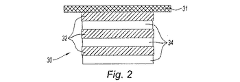
図2に見られるように、積層体30が、互いに積み重ねられた複数の層の形態で示されている。一実施形態によれば、積層体が、粘弾性材料の層32および剛性材料からなるカウンタ層34を備える。積層体は、粘弾性層32によって減衰対象の構造体の表面31へと貼り付けられている。
As can be seen in FIG. 2, the
粘弾性とは、変形を受けたときに機械的なエネルギーの散逸および保存を同時に達成することによって粘性および弾性の両方の挙動を呈する固体または液体の特性である。 Viscoelasticity is a property of a solid or liquid that exhibits both viscous and elastic behavior by simultaneously achieving mechanical energy dissipation and storage when subjected to deformation.
所望の熱および周波数の動作範囲においては、カウンタ層34の剛性材料の弾性の等方性または異方性が、粘弾性材料の等方性または異方性よりも優位である。これに限られるわけではないが、例として、層34の材料は、金属または複合材料のタイプであってよく、層32の材料は、ゴム、シリコーン、ポリマー、ガラス、またはエポキシ樹脂のタイプであってよい。材料は、所定の温度および周波数範囲に対応して予想される構成においてエネルギーの散逸に関して有効でなければならない。変形および速度にて表現される特有のせん断弾性係数にもとづいて、選択が行われる。
In the desired heat and frequency operating range, the elastic material isotropic or anisotropy of the
他の実施形態によれば、積層体が、粘弾性材料からなるいくつかの層32と剛性材料からなるいくつかのカウンタ層34とを、交互に配置して有する。図2の例(これに限られるわけではない)が、粘弾性材料からなる3つの層32と剛性材料からなる3つのカウンタ層34とを有する減衰積層体を示している。用途に応じ、粘弾性材料の層32および剛性材料の層34は、同じ寸法または異なる寸法を有する。積層体が、複数の層32を備える場合、複数の層32が、すべて同じ機械的特性を有しても、あるいは異なる機械的特性を有してもよい。積層体が、複数のカウンタ層34を有する場合、複数のカウンタ層34が、すべて同じ特性を有しても、あるいは異なる機械的特性を有してもよい。層32およびカウンタ層34は、好ましくは、接着剤のフィルムによる接着または重合によって互いに貼り付けられる。
According to another embodiment, the laminate has alternating
図3が、第1の実施形態を示している。ステータセクタ40(この場合には、タービンの上流側案内羽根部材のセクタ)が、片側にシール部材42を支持し、他方の側にガス流の内壁を形成している半径方向内側のリング部材41を備える。複数の羽根43が、リング部材41から半径方向外側のリング部材44へと放射状に延びている。部材44は、片面において羽根43をスウェプトするガス流の外壁を形成している。リング部材44は、上流側および下流側の取り付け部材45および46を備える。部材44の外表面44eは、実質的に円柱形の形状である。2つの層(すなわち、粘弾性層32および剛性カウンタ層34)からなる積層体30が、この表面の部分44eへと取り付けられている。積層体30は、粘弾性層を表面の部分44eへと接着し、あるいは重合させることによって取り付けられている。この積層体は、表面の部分44eの軸方向の部分を覆って広がっている。好ましくは、周方向において、セクタの全体を覆って広がっている。セクタ40がタービンのケーシングに設置されると、セクタ40によって、上流側案内羽根部材の外表面の全周が減衰積層体によって覆われている完全な上流側案内羽根部材インペラが形成される。
FIG. 3 shows the first embodiment. A stator sector 40 (in this case, a sector of the upstream guide vane member of the turbine) supports a
動作時、ステータ羽根リングまたは上流側案内羽根部材セクタの振動モードだけでなく、羽根の振動モードもが、ガス流の空気力学的な流れを乱すことなく、積層体によって減衰される。 In operation, not only the vibration mode of the stator blade ring or upstream guide blade member sector, but also the vibration mode of the blade is attenuated by the stack without disturbing the aerodynamic flow of the gas flow.
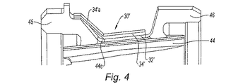
図4が、第2の実施形態を示している。内側リング部材41および外側リング部材44を備える上述と同じステータ羽根リングまたは上流側案内羽根部材セクタについて、半径方向外側の部材44の部分の軸断面を見ることができる。ここでも、減衰積層体30’が、粘弾性層32’および剛性カウンタ層34’を備える。相違点は、ステータ羽根リングまたは上流側案内羽根部材セクタとの接続の様式にある。剛性カウンタ層34’が、外側リング部材44のより頑丈で厚い部位(この例では、上流側の取り付け部材45である)へと押し付ける横延長部34’aを備える。横延長部34’aは、取り付け部材45へとボルトまたは他の手段によって取り付けられている。これが、ステータが耐えなければならないさまざまな出来事の際に、減衰積層体のより良好な耐性が保証される理由である。この場合、積層体は、必ずしもリング部44の外表面へと接着される必要はない。機械的な取り付けが、振動が生じたときにその振動が粘弾性層へと伝達されるように、この表面へと積層体を押圧している。先の場合と同様、ステータの外側リングへと粘弾性減衰積層体を適用するという解決策を、状況に合わせて適応させることが可能である。
FIG. 4 shows a second embodiment. For the same stator vane ring or upstream guide vane member sector as described above with the
1 ターボ機械
2 ファン
30、30’ 積層体
31 減衰対象の構造体の表面
32、32’ 粘弾性材料の層
34、34’ 剛性材料からなるカウンタ層
34’a 横延長部、機械的な取り付け部材
40 ステータセクタ
41 内側リング部材
42 シール部材
43 羽根
44 外側リング部材
44e 外表面
45 上流側の取り付け部材
46 下流側の取り付け部材
DESCRIPTION OF SYMBOLS 1 Turbomachine 2
Claims (14)
第2のリングが、円柱形の外表面部分(44e)を有し、
前記外表面部分(44e)に、粘弾性材料からなる少なくとも1つの層(32)を前記表面部分(44e)および剛性材料からなる1つのカウンタ層(34)に接触させて備える少なくとも1つの振動減衰積層体(30、30’)が取り付けられている、ステータ。 A stator vane ring or upstream guide vane member comprising a plurality of concentric rings, a plurality of vanes (43) arranged radially between a first inner ring (42) and a second outer ring (44); Forming a turbomachine stator,
The second ring has a cylindrical outer surface portion (44e);
At least one vibration damping comprising at least one layer (32) of viscoelastic material in contact with the outer surface portion (44e) and one counter layer (34) of rigid material. The stator to which the laminate (30, 30 ') is attached.
Applications Claiming Priority (2)
| Application Number | Priority Date | Filing Date | Title |
|---|---|---|---|
| FR0704580A FR2918108B1 (en) | 2007-06-26 | 2007-06-26 | SHOCK ABSORBER DEVICE FOR TURBOMACHINE STATOR |
| FR0704580 | 2007-06-26 |
Publications (2)
| Publication Number | Publication Date |
|---|---|
| JP2009024697A JP2009024697A (en) | 2009-02-05 |
| JP5035138B2 true JP5035138B2 (en) | 2012-09-26 |
Family
ID=38983346
Family Applications (1)
| Application Number | Title | Priority Date | Filing Date |
|---|---|---|---|
| JP2008165446A Active JP5035138B2 (en) | 2007-06-26 | 2008-06-25 | Damping device for turbomachine stator |
Country Status (7)
| Country | Link |
|---|---|
| US (1) | US8147191B2 (en) |
| EP (1) | EP2009242B1 (en) |
| JP (1) | JP5035138B2 (en) |
| CN (1) | CN101333943B (en) |
| CA (1) | CA2635639C (en) |
| FR (1) | FR2918108B1 (en) |
| RU (1) | RU2486351C2 (en) |
Families Citing this family (22)
| Publication number | Priority date | Publication date | Assignee | Title |
|---|---|---|---|---|
| EP2216511B1 (en) * | 2009-02-05 | 2012-05-02 | Siemens Aktiengesellschaft | An annular vane assembly for a gas turbine engine |
| DE102009010185A1 (en) * | 2009-02-23 | 2010-08-26 | Mtu Aero Engines Gmbh | Gas turbine engine |
| FR2961553B1 (en) * | 2010-06-18 | 2012-08-31 | Snecma | ANGULAR RECTIFIER SECTOR FOR TURBOMACHINE COMPRESSOR, TURBOMACHINE RECTIFIER AND TURBOMACHINE COMPRISING SUCH A SECTOR |
| JP5660883B2 (en) * | 2010-12-22 | 2015-01-28 | 三菱日立パワーシステムズ株式会社 | Steam turbine vane, steam turbine |
| US8696311B2 (en) * | 2011-03-29 | 2014-04-15 | Pratt & Whitney Canada Corp. | Apparatus and method for gas turbine engine vane retention |
| ITTO20110728A1 (en) * | 2011-08-04 | 2013-02-05 | Avio Spa | STATIC PALLETED SEGMENT OF A GAS TURBINE FOR AERONAUTICAL MOTORS |
| AU2012216660B2 (en) * | 2011-09-13 | 2016-10-13 | Black & Decker Inc | Tank dampening device |
| JP2013104297A (en) * | 2011-11-10 | 2013-05-30 | Mitsubishi Heavy Ind Ltd | Steam turbine low-pressure casing |
| US9194251B2 (en) * | 2012-08-10 | 2015-11-24 | United Technologies Corporation | Duct damper |
| US9243509B2 (en) | 2012-09-04 | 2016-01-26 | General Electric Company | Stator vane assembly |
| JP6150548B2 (en) * | 2013-02-13 | 2017-06-21 | 三菱重工業株式会社 | Rotating machine blade |
| FR3013072B1 (en) * | 2013-11-14 | 2018-04-20 | Safran Aircraft Engines | ANNULAR ELEMENT OF TURBOMACHINE HOUSING |
| US9845702B2 (en) * | 2015-04-27 | 2017-12-19 | United Technologies Corporation | Stator damper |
| US10808574B2 (en) | 2016-09-13 | 2020-10-20 | General Electric Company | Turbomachine stator travelling wave inhibitor |
| US10443625B2 (en) | 2016-09-21 | 2019-10-15 | General Electric Company | Airfoil singlets |
| US10612405B2 (en) * | 2017-01-13 | 2020-04-07 | United Technologies Corporation | Stator outer platform sealing and retainer |
| DE102018204876A1 (en) * | 2018-03-29 | 2019-10-02 | Thyssenkrupp Ag | Electric motor with a slanted stator and / or rotor containing at least one layer of a composite material |
| US11021995B2 (en) * | 2018-08-06 | 2021-06-01 | Raytheon Technologies Corporation | Imbalance damping devices for gas turbine engine fan shaft bearings |
| US10851942B1 (en) * | 2019-05-30 | 2020-12-01 | Caterpillar Paving Products Inc. | Vibratory system lubrication remaining useful life |
| CN112483598B (en) * | 2020-10-27 | 2022-11-29 | 中国船舶重工集团公司第七0三研究所 | Large-displacement composite-rigidity conical column hybrid shock absorber of gas turbine generator set |
| CN114233398A (en) * | 2021-12-13 | 2022-03-25 | 中国船舶重工集团公司第七0三研究所 | Composite elastic cantilever type gas turbine support ring vibration-damping and impact-resisting assembly device |
| US20240003543A1 (en) * | 2022-06-29 | 2024-01-04 | General Electric Company | Acoustic liner for a gas turbine engine |
Family Cites Families (14)
| Publication number | Priority date | Publication date | Assignee | Title |
|---|---|---|---|---|
| GB2043798B (en) * | 1979-03-14 | 1983-01-12 | Rolls Royce | Gas turbine stator vane assembly |
| SU1108221A1 (en) * | 1983-04-08 | 1984-08-15 | Куйбышевский Ордена Трудового Красного Знамени Авиационный Институт Им.Акад.С.П.Королева | Axial turbomachine inlet vanes |
| FR2642113A1 (en) * | 1989-01-20 | 1990-07-27 | Rolls Royce Plc | Method for manufacturing a set of fixed-blading fins for an axial-flow compressor and set of fins obtained by this method |
| DE4329014C1 (en) * | 1993-08-28 | 1995-01-05 | Mtu Muenchen Gmbh | Rotor housing, especially housing for turbine engines |
| US5494404A (en) * | 1993-12-22 | 1996-02-27 | Alliedsignal Inc. | Insertable stator vane assembly |
| US6102664A (en) * | 1995-12-14 | 2000-08-15 | The United States Of America As Represented By The Administrator Of The National Aeronautics And Space Administration | Blading system and method for controlling structural vibrations |
| AU2411999A (en) * | 1998-02-24 | 1999-09-15 | Lm Glasfiber A/S | Wind turbine blade |
| US6494679B1 (en) * | 1999-08-05 | 2002-12-17 | General Electric Company | Apparatus and method for rotor damping |
| US6471484B1 (en) | 2001-04-27 | 2002-10-29 | General Electric Company | Methods and apparatus for damping rotor assembly vibrations |
| US20030139217A1 (en) * | 2002-01-23 | 2003-07-24 | Lin Zhu | Shaft damper |
| US6969239B2 (en) * | 2002-09-30 | 2005-11-29 | General Electric Company | Apparatus and method for damping vibrations between a compressor stator vane and a casing of a gas turbine engine |
| GB2400415B (en) * | 2003-04-11 | 2006-03-08 | Rolls Royce Plc | Vane mounting |
| DE60318852T2 (en) * | 2003-10-03 | 2009-02-05 | General Electric Co. | Apparatus and method for damping vibrations between compressor vanes and the casing of a gas turbine |
| US7824152B2 (en) * | 2007-05-09 | 2010-11-02 | Siemens Energy, Inc. | Multivane segment mounting arrangement for a gas turbine |
-
2007
- 2007-06-26 FR FR0704580A patent/FR2918108B1/en not_active Expired - Fee Related
-
2008
- 2008-06-24 US US12/144,960 patent/US8147191B2/en active Active
- 2008-06-25 JP JP2008165446A patent/JP5035138B2/en active Active
- 2008-06-25 EP EP08159045A patent/EP2009242B1/en active Active
- 2008-06-25 RU RU2008125918/06A patent/RU2486351C2/en active
- 2008-06-26 CN CN2008101114875A patent/CN101333943B/en active Active
- 2008-06-26 CA CA2635639A patent/CA2635639C/en active Active
Also Published As
| Publication number | Publication date |
|---|---|
| FR2918108B1 (en) | 2009-10-02 |
| EP2009242A1 (en) | 2008-12-31 |
| JP2009024697A (en) | 2009-02-05 |
| RU2486351C2 (en) | 2013-06-27 |
| CA2635639C (en) | 2015-01-27 |
| FR2918108A1 (en) | 2009-01-02 |
| CN101333943B (en) | 2013-03-20 |
| US8147191B2 (en) | 2012-04-03 |
| EP2009242B1 (en) | 2012-06-20 |
| CA2635639A1 (en) | 2008-12-26 |
| CN101333943A (en) | 2008-12-31 |
| US20090004000A1 (en) | 2009-01-01 |
| RU2008125918A (en) | 2009-12-27 |
Similar Documents
| Publication | Publication Date | Title |
|---|---|---|
| JP5035138B2 (en) | Damping device for turbomachine stator | |
| JP5281828B2 (en) | Damping device for turbomachine shaft | |
| US8226367B2 (en) | Movable impeller for a turbojet and turbojet comprising same | |
| JP5427381B2 (en) | Vibration damping device for composite blades | |
| US8801385B2 (en) | Vibration damper device for turbomachine blade attachments, associated turbomachine and associated engines | |
| US8500410B2 (en) | Blade made of composite material comprising a damping device | |
| US8061967B2 (en) | Panel for supporting abradable material in a turbomachine | |
| JP2009068491A (en) | Lever for rotating about its pivot turbomachine variable-pitch stator vane | |
| US10294965B2 (en) | Compression system for a turbine engine | |
| CA2614406A1 (en) | Methods and apparatus for fabricating a fan assembly for use with turbine engines | |
| US20070183891A1 (en) | Guide vane arrangements for gas turbine engines | |
| GB2571177A (en) | Damping device | |
| RU2709752C2 (en) | Sealing ring of internal ring of last stage of gas turbine engine axial compressor | |
| CN114423927A (en) | Attachment of an acoustic shroud to a casing section for an aircraft turbine engine | |
| US11466571B1 (en) | Damping device | |
| CN114026311B (en) | Turbine assembly with damper | |
| CN114080490A (en) | Assembly for a turbomachine |
Legal Events
| Date | Code | Title | Description |
|---|---|---|---|
| A621 | Written request for application examination |
Free format text: JAPANESE INTERMEDIATE CODE: A621 Effective date: 20110624 |
|
| A977 | Report on retrieval |
Free format text: JAPANESE INTERMEDIATE CODE: A971007 Effective date: 20120524 |
|
| TRDD | Decision of grant or rejection written | ||
| A01 | Written decision to grant a patent or to grant a registration (utility model) |
Free format text: JAPANESE INTERMEDIATE CODE: A01 Effective date: 20120605 |
|
| A01 | Written decision to grant a patent or to grant a registration (utility model) |
Free format text: JAPANESE INTERMEDIATE CODE: A01 |
|
| A61 | First payment of annual fees (during grant procedure) |
Free format text: JAPANESE INTERMEDIATE CODE: A61 Effective date: 20120618 |
|
| FPAY | Renewal fee payment (event date is renewal date of database) |
Free format text: PAYMENT UNTIL: 20150713 Year of fee payment: 3 |
|
| R150 | Certificate of patent or registration of utility model |
Ref document number: 5035138 Country of ref document: JP Free format text: JAPANESE INTERMEDIATE CODE: R150 Free format text: JAPANESE INTERMEDIATE CODE: R150 |
|
| R250 | Receipt of annual fees |
Free format text: JAPANESE INTERMEDIATE CODE: R250 |
|
| R250 | Receipt of annual fees |
Free format text: JAPANESE INTERMEDIATE CODE: R250 |
|
| R250 | Receipt of annual fees |
Free format text: JAPANESE INTERMEDIATE CODE: R250 |
|
| R250 | Receipt of annual fees |
Free format text: JAPANESE INTERMEDIATE CODE: R250 |
|
| R250 | Receipt of annual fees |
Free format text: JAPANESE INTERMEDIATE CODE: R250 |
|
| R250 | Receipt of annual fees |
Free format text: JAPANESE INTERMEDIATE CODE: R250 |
|
| R250 | Receipt of annual fees |
Free format text: JAPANESE INTERMEDIATE CODE: R250 |
|
| R250 | Receipt of annual fees |
Free format text: JAPANESE INTERMEDIATE CODE: R250 |
|
| R250 | Receipt of annual fees |
Free format text: JAPANESE INTERMEDIATE CODE: R250 |