EP2216511B1 - An annular vane assembly for a gas turbine engine - Google Patents
An annular vane assembly for a gas turbine engine Download PDFInfo
- Publication number
- EP2216511B1 EP2216511B1 EP09152225A EP09152225A EP2216511B1 EP 2216511 B1 EP2216511 B1 EP 2216511B1 EP 09152225 A EP09152225 A EP 09152225A EP 09152225 A EP09152225 A EP 09152225A EP 2216511 B1 EP2216511 B1 EP 2216511B1
- Authority
- EP
- European Patent Office
- Prior art keywords
- strip
- rail
- recesses
- resilient
- assembly
- Prior art date
- Legal status (The legal status is an assumption and is not a legal conclusion. Google has not performed a legal analysis and makes no representation as to the accuracy of the status listed.)
- Not-in-force
Links
- 230000000295 complement effect Effects 0.000 claims description 4
- 230000007246 mechanism Effects 0.000 description 11
- 230000037431 insertion Effects 0.000 description 6
- 238000003780 insertion Methods 0.000 description 6
- 230000013011 mating Effects 0.000 description 2
- 239000000470 constituent Substances 0.000 description 1
- 230000007797 corrosion Effects 0.000 description 1
- 238000005260 corrosion Methods 0.000 description 1
- 238000006073 displacement reaction Methods 0.000 description 1
- 238000004519 manufacturing process Methods 0.000 description 1
- 230000007704 transition Effects 0.000 description 1
Images

Classifications
-
- F—MECHANICAL ENGINEERING; LIGHTING; HEATING; WEAPONS; BLASTING
- F01—MACHINES OR ENGINES IN GENERAL; ENGINE PLANTS IN GENERAL; STEAM ENGINES
- F01D—NON-POSITIVE DISPLACEMENT MACHINES OR ENGINES, e.g. STEAM TURBINES
- F01D9/00—Stators
- F01D9/02—Nozzles; Nozzle boxes; Stator blades; Guide conduits, e.g. individual nozzles
- F01D9/04—Nozzles; Nozzle boxes; Stator blades; Guide conduits, e.g. individual nozzles forming ring or sector
- F01D9/042—Nozzles; Nozzle boxes; Stator blades; Guide conduits, e.g. individual nozzles forming ring or sector fixing blades to stators
-
- F—MECHANICAL ENGINEERING; LIGHTING; HEATING; WEAPONS; BLASTING
- F01—MACHINES OR ENGINES IN GENERAL; ENGINE PLANTS IN GENERAL; STEAM ENGINES
- F01D—NON-POSITIVE DISPLACEMENT MACHINES OR ENGINES, e.g. STEAM TURBINES
- F01D25/00—Component parts, details, or accessories, not provided for in, or of interest apart from, other groups
- F01D25/24—Casings; Casing parts, e.g. diaphragms, casing fastenings
- F01D25/246—Fastening of diaphragms or stator-rings
Definitions
- This invention relates to an annular vane assembly for a gas turbine engine.
- the invention relates to an annular vane assembly for a gas turbine engine, the assembly including a vane segment comprising an arcuate rail and at least one vane that extends radially inwardly from the arcuate rail, the assembly also including a hollow cylindrical casing in the inside curved surface of which is formed an annular groove for receiving the arcuate rail of the vane segment.
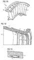
- FIG. 1a One known vane segment 1 is shown in Fig 1a , and comprises a radially inner arcuate rail 3, a radially outer arcuate rail 5, and vanes 7 that extend radially between the inner and outer rails.
- the outer rail 5 has flanges 9 that run along either side of the rail.
- One known hollow cylindrical casing 11 is shown in Fig 1b , and includes in its inside curved surface 13 a plurality of annular grooves 15. Each annular groove 15 has recesses 17 that run along either side of the groove.
- the vane segment 1 of Fig 1a is fitted to the casing 11 of Fig 1b by aligning the ends of the flanges 9 of the outer rail 5 of the vane segment with the ends of the recesses 17 of an annular groove 15 of the casing, and sliding the flanges circumferentially around the recesses so that the outer rail slides circumferentially around the annular groove.
- Fig 1c shows the mating relationship between the outer rail 5 and the annular groove 15 when the vane segment 1 is fitted to the casing 11.
- the known annular vane assembly of Figs 1a to 1c is an assembly of a compressor of a gas turbine engine.
- vane segment 1 Once fitted to casing 11, can be secured in place.
- Fig 1c One such mechanism is as shown in Fig 1c .
- the flanges 9 are a tight fit within the recesses 17, i.e. there is a minimum clearance between the radially inwardly/outwardly facing surfaces of the flanges/recesses, thereby to hold the vane segment 1 at a predetermined position in the radial direction.
- This mechanism although low cost, gives rise to problems in assembly if there has been minor distortion in the physical form of the vane segment during its fabrication. Also, if it is required to remove the vane segment from the casing following actual in service use of the gas turbine engine, then this can be very difficult due to corrosion and distortion of the vane segment during use.
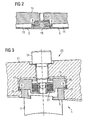
- FIG 2 Another mechanism is as shown in Fig 2 .
- the annular grooves 15 are formed by clamp rings 19 bolted to the inside curved surface 13 of the hollow cylindrical casing 11 by means of bolts (not shown) that pass via holes 21 from the outside of the casing to the clamp rings. Removal of vane segments is made easy by removal of the clamp rings.
- This mechanism although solving the problems of the Fig 1c mechanism, is expensive.
- FIG. 3 A further mechanism is shown in Fig 3 .
- the cross section of the annular groove 15 is such as to loosely fit the radially outer arcuate rail 5 of the vane segment 1, and a spring pack 23 is used to secure the flanges 9 of the rail 5 against the radially outwardly facing surfaces 25 of the recesses 17 of the groove 15.
- the spring pack 23 comprises a spring 27, a spring holder 29, and a jacking screw 31. Tightening of jacking screw 31 causes spring holder 29 to bear down upon flanges 9, clamping flanges 9 onto surfaces 25 with a controlled spring load. Vane segment 1 is now secured in position. In use temperature change may give rise to relative movement between constituent parts. The controlled spring load allows some such movement.
- FR-A-2 282 550 discloses a compressor stator having a one piece housing in which a circumferential groove having a radially inner part of reduced width is formed for each stage in the wall of the cavity of the housing and communicates with the exterior of the housing by way of at least one radial opening having sufficient size to provide a passage for a vane base.
- the vane bases are disposed in a contiguous fashion in the groove and are radially supported by said inner part of the latter.
- a chain surrounds all the bases and bears radially against each one thereof.
- an annular vane assembly for a gas turbine engine, the assembly including a vane segment comprising an arcuate rail and at least one vane that extends radially inwardly from the arcuate rail, the assembly also including a hollow cylindrical casing in the inside curved surface of which is formed an annular groove for receiving the arcuate rail of the vane segment, the arcuate rail being secured in the annular groove by means of one or more resilient strips interposed between the rail and the groove, the or each resilient strip comprising a planar main body and sprung wings that extend to either side of the main body, characterised in that the wings are angled with respect to the plane of the main body, and the or each resilient strip is moveable circumferentially between (i) a first position in which the strip exerts a force radially on the arcuate rail to secure the rail in the annular groove and (ii) a second position in which the wings of the strip occupy recesses in the assembly to relieve the radial force and release the rail in the
- the rail includes flanges that run along either side of the rail, and the groove includes recesses that run along either side of the groove, first surfaces comprising radially inwardly facing surfaces of the flanges engaging with second surfaces comprising radially outwardly facing surfaces of the recesses, and the resilient strip is interposed between third surfaces comprising radially outwardly facing surfaces of the flanges and fourth surfaces comprising radially inwardly facing surfaces of the recesses, in the first position (i) the wings of the strip exerting a radially inward force on the third surfaces and (ii) the main body of the strip exerting a radially outward force on the fourth surfaces.
- the recesses comprise recesses in a further strip of the assembly, the further strip being interposed between the resilient strip and the third surfaces, in the first position the wings of the resilient strip exerting the radially inward force on the third surfaces via the agency of the further strip, the recesses comprising recesses in each side of the further strip, the circumferential movement of the resilient strip between the first and second positions being circumferential movement relative to the further strip.
- the recesses of the further strip include encountered sides that are encountered by the wings of the resilient strip when the resilient strip is moved circumferentially relative to the further strip from the second to the first positions, and wherein the encountered sides subtend an angle to the circumferential direction of substantially less than 90 degrees.
- the ends of the resilient and/or further strips include a tooling hole whereby a tool can be attached to the resilient/further strip to facilitate the circumferential movement of the resilient strip relative to the further strip between the first and second positions.
- the arcuate rail and annular groove incorporate a complementary protrusion and depression to circumferentially locate the rail within the groove.
- the or each vane of the vane segment extends radially inwardly to a further arcuate rail of the vane segment.
- the assembly according to any one of the preceding eight paragraphs may be a compressor assembly.
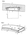
- vane segment 1 of Fig 1a is fitted to hollow cylindrical casing 11 of Fig 1b in precisely the manner described above (the ends of flanges 9 are aligned with the ends of recesses 17, and flanges 9 are slid circumferentially around recesses 17).
- resilient and further strips 33, 35 are then inserted between radially outwardly facing surfaces 37 of flanges 9 and radially inwardly facing surfaces 39 of recesses 17.
- Fig 5 shows strips 33, 35 lying atop flanges 9. In Fig 5 casing 11 atop strips 33, 35 is not shown.
- Resilient strip 33 lies radially outwardly of further strip 35 and against surfaces 39.
- Further strip 35 lies radially inwardly of resilient strip 33 and against surfaces 37.
- Resilient strip 33 comprises a planar main body 41 and sprung wings 43 that extend to either side of main body 41. Wings 43 are angled with respect to the plane of main body 41 such that (i) main body 41 exerts a radially outward force on surfaces 39, and (ii) wings 43 exert a radially inward force on further strip 35. Further strip 35 in turn exerts a radially inward force on surfaces 37. This causes radially inwardly facing surfaces 45 of flanges 9 to be biased against radially outwardly facing surfaces 47 of recesses 17, clamping flanges 9 onto surfaces 47. In this manner, vane segment 1 is securely held in position in annular groove 15 of casing 11.
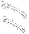
- strip 35 includes recesses 49 in either side. Recesses 49 come into play when strips 33, 35 are inserted between, or removed from insertion between, surfaces 37 of flanges 9 and surfaces 39 of recesses 17.
- strips 33, 35 are positioned relative to one another as shown in Fig 6 .
- Strip 33 lies on top of strip 35 (radially outwardly of strip 35) but is displaced relative to strip 35 in the direction of the lengths of strips 33, 35 by a distance such that wings 43 of strip 33 occupy recesses 49 of strip 35 (or are displaced past an end of strip 35).
- the positioning of Fig 6 is to be contrasted to the positioning of Fig 7 , where there has been no displacement of strip 33 in the direction of the lengths of strips 33, 35 (and the ends of strips 33, 35 are in register). It is the positioning of Fig 7 that strips 33, 35 have when strips 33, 35 are in their in use positions between vane segment 1 and annular groove 15 of casing 11.
- strip 33 is slid circumferentially relative to strip 35 in order to bring strips 33, 35 to the positioning shown in Fig 7 .
- This brings wings 43 into engagement with strip 35, lifting strip 33 away from strip 35 (in a radially outward direction).
- the result is the clamping of vane segment 1 in place in annular groove 15, as described above with reference to Figs 4 and 5 .
- strips 33, 35 are the reverse of insertion.
- strip 33 is slid circumferentially relative to strip 35 to bring strips 33, 35 to the positioning of Fig 6 .
- Strips 33, 35 can then be removed relatively easily from between surfaces 37 of flanges 9 and surfaces 39 of recesses 17 (vane segment 1 can then be removed).
- strip 33 is slid circumferentially relative to strip 35 to bring wings 43 of strip 33 into engagement with strip 35.
- strip 33 is slid circumferentially relative to strip 35 to bring wings 43 of strip 33 into engagement with strip 35.
- strips 33, 35 the reverse occurs.
- holes 51 are provided in the ends of strips 33, 35 whereby an appropriate tool can be attached to strips 33, 35 to facilitate the sliding.
- the holes 51 of the two strips 33, 35 are of the same size, and, in the positioning of Fig 7 , concentric.
- Recesses 49 of strip 35 include sides 53 that are encountered by wings 43 of strip 33 when transition is occurring from the positioning of Fig 6 to the positioning of Fig 7 . To ease the riding-up of wings 43 onto strip 35, sides 53 subtend an angle to the circumferential direction of substantially less than 90 degrees.
- arcuate rail 5 of vane segment 1 and annular groove 15 of casing 11 incorporate a complementary protrusion 55 and depression 57 to circumferentially locate rail 5 within groove 15 prior to insertion of strips 33, 35.
- one 33 or two 33, 35 strips are used between radially outwardly facing surfaces 37 of flanges 9 and radially inwardly facing surfaces 39 of recesses 17. It is to be appreciated that instead one or two pairs of strips could be used between radially outwardly facing surfaces 47 of recesses 17 and radially inwardly facing surfaces 45 of flanges 9, one strip of the or each pair being located at each side of rail 5. The one or two strips at each side of rail 5 would operate in corresponding manner to one strip 33 or two strips 33, 35.
Abstract
Description
- This invention relates to an annular vane assembly for a gas turbine engine.
- More particularly, the invention relates to an annular vane assembly for a gas turbine engine, the assembly including a vane segment comprising an arcuate rail and at least one vane that extends radially inwardly from the arcuate rail, the assembly also including a hollow cylindrical casing in the inside curved surface of which is formed an annular groove for receiving the arcuate rail of the vane segment.
- One known vane segment 1 is shown in
Fig 1a , and comprises a radially innerarcuate rail 3, a radially outerarcuate rail 5, andvanes 7 that extend radially between the inner and outer rails. Theouter rail 5 hasflanges 9 that run along either side of the rail. One known hollowcylindrical casing 11 is shown inFig 1b , and includes in its inside curved surface 13 a plurality ofannular grooves 15. Eachannular groove 15 hasrecesses 17 that run along either side of the groove. - The vane segment 1 of
Fig 1a is fitted to thecasing 11 ofFig 1b by aligning the ends of theflanges 9 of theouter rail 5 of the vane segment with the ends of therecesses 17 of anannular groove 15 of the casing, and sliding the flanges circumferentially around the recesses so that the outer rail slides circumferentially around the annular groove.Fig 1c shows the mating relationship between theouter rail 5 and theannular groove 15 when the vane segment 1 is fitted to thecasing 11. - The known annular vane assembly of
Figs 1a to 1c is an assembly of a compressor of a gas turbine engine. - There are various mechanisms by which vane segment 1, once fitted to
casing 11, can be secured in place. - One such mechanism is as shown in
Fig 1c . Theflanges 9 are a tight fit within therecesses 17, i.e. there is a minimum clearance between the radially inwardly/outwardly facing surfaces of the flanges/recesses, thereby to hold the vane segment 1 at a predetermined position in the radial direction. This mechanism, although low cost, gives rise to problems in assembly if there has been minor distortion in the physical form of the vane segment during its fabrication. Also, if it is required to remove the vane segment from the casing following actual in service use of the gas turbine engine, then this can be very difficult due to corrosion and distortion of the vane segment during use. - Another mechanism is as shown in
Fig 2 . Theannular grooves 15 are formed byclamp rings 19 bolted to the insidecurved surface 13 of the hollowcylindrical casing 11 by means of bolts (not shown) that pass viaholes 21 from the outside of the casing to the clamp rings. Removal of vane segments is made easy by removal of the clamp rings. This mechanism, although solving the problems of theFig 1c mechanism, is expensive. - A further mechanism is shown in
Fig 3 . The cross section of theannular groove 15 is such as to loosely fit the radially outerarcuate rail 5 of the vane segment 1, and aspring pack 23 is used to secure theflanges 9 of therail 5 against the radially outwardly facingsurfaces 25 of therecesses 17 of thegroove 15. Thespring pack 23 comprises aspring 27, aspring holder 29, and ajacking screw 31. Tightening of jackingscrew 31 causesspring holder 29 to bear down uponflanges 9, clampingflanges 9 ontosurfaces 25 with a controlled spring load. Vane segment 1 is now secured in position. In use temperature change may give rise to relative movement between constituent parts. The controlled spring load allows some such movement. Loosening ofjacking screw 31unclamps flanges 9, releasing vane segment 1 for removal fromannular groove 15. Typically two or threespring packs 23 are used per vane segment. The mechanism ofFig 3 suffers from the disadvantage that it is complex. -
FR-A-2 282 550 - According to the present invention there is provided an annular vane assembly for a gas turbine engine, the assembly including a vane segment comprising an arcuate rail and at least one vane that extends radially inwardly from the arcuate rail, the assembly also including a hollow cylindrical casing in the inside curved surface of which is formed an annular groove for receiving the arcuate rail of the vane segment, the arcuate rail being secured in the annular groove by means of one or more resilient strips interposed between the rail and the groove, the or each resilient strip comprising a planar main body and sprung wings that extend to either side of the main body, characterised in that the wings are angled with respect to the plane of the main body, and the or each resilient strip is moveable circumferentially between (i) a first position in which the strip exerts a force radially on the arcuate rail to secure the rail in the annular groove and (ii) a second position in which the wings of the strip occupy recesses in the assembly to relieve the radial force and release the rail in the groove, the recesses comprising either (a) recesses in a further strip of the assembly interposed between the rail and the groove or (b) recesses in the rail.
- In an assembly according to the preceding paragraph, it is preferable that there is one resilient strip and in the first position it exerts a radially inward force on the arcuate rail.
- In an assembly according to the preceding paragraph, it is preferable that the rail includes flanges that run along either side of the rail, and the groove includes recesses that run along either side of the groove, first surfaces comprising radially inwardly facing surfaces of the flanges engaging with second surfaces comprising radially outwardly facing surfaces of the recesses, and the resilient strip is interposed between third surfaces comprising radially outwardly facing surfaces of the flanges and fourth surfaces comprising radially inwardly facing surfaces of the recesses, in the first position (i) the wings of the strip exerting a radially inward force on the third surfaces and (ii) the main body of the strip exerting a radially outward force on the fourth surfaces.
- In an assembly according to the preceding paragraph, it is preferable that the recesses comprise recesses in a further strip of the assembly, the further strip being interposed between the resilient strip and the third surfaces, in the first position the wings of the resilient strip exerting the radially inward force on the third surfaces via the agency of the further strip, the recesses comprising recesses in each side of the further strip, the circumferential movement of the resilient strip between the first and second positions being circumferential movement relative to the further strip.
- In an assembly according to the preceding paragraph, it is preferable that the recesses of the further strip include encountered sides that are encountered by the wings of the resilient strip when the resilient strip is moved circumferentially relative to the further strip from the second to the first positions, and wherein the encountered sides subtend an angle to the circumferential direction of substantially less than 90 degrees.
- In an assembly according to either of the preceding two paragraphs, it is preferable that the ends of the resilient and/or further strips include a tooling hole whereby a tool can be attached to the resilient/further strip to facilitate the circumferential movement of the resilient strip relative to the further strip between the first and second positions.
- In an assembly according to any one of the preceding six paragraphs, it is preferable that the arcuate rail and annular groove incorporate a complementary protrusion and depression to circumferentially locate the rail within the groove.
- In an assembly according to any one of the preceding seven paragraphs, it is preferable that the or each vane of the vane segment extends radially inwardly to a further arcuate rail of the vane segment.
- The assembly according to any one of the preceding eight paragraphs may be a compressor assembly.
- The invention will now be described, by way of example, with reference to the accompanying drawings, in which:
-
Fig 1a , already referred to, is a perspective view of a known vane segment; -
Fig 1b , already referred to, is a perspective view of a known hollow cylindrical casing to which fits the known vane segment ofFig 1a ; -
Fig 1c , already referred to, shows a mating relationship between an outer rail of the vane segment ofFig 1a and an annular groove of the casing ofFig 1b ; -
Fig 2 , already referred to, shows a mechanism by which a vane segment, once fitted to a casing, can be secured in place; -
Fig 3 , already referred to, shows a further mechanism by which a vane segment, once fitted to a casing, can be secured in place; -
Fig 4 shows a mechanism according to the present invention by which the vane segment ofFig 1a , once fitted to the casing ofFig 1b , can be secured in place; -
Fig 5 is a partial perspective view showing resilient and further strips ofFig 4 lying atop a rail ofFig 4 ; -
Fig 6 is a perspective view of the resilient and further strips in a first positioning; -
Fig 7 is a perspective view of the resilient and further strips in a second positioning; and -
Figs 8 and 9 illustrate a complementary protrusion and depression incorporated in a rail and groove ofFig 4 . - Referring to
Fig 4 , vane segment 1 ofFig 1a is fitted to hollowcylindrical casing 11 ofFig 1b in precisely the manner described above (the ends offlanges 9 are aligned with the ends ofrecesses 17, andflanges 9 are slid circumferentially around recesses 17). In a manner described in more detail below, resilient andfurther strips surfaces 37 offlanges 9 and radially inwardly facingsurfaces 39 ofrecesses 17.Fig 5 shows strips flanges 9. InFig 5 casing 11atop strips Resilient strip 33 lies radially outwardly offurther strip 35 and againstsurfaces 39.Further strip 35 lies radially inwardly ofresilient strip 33 and againstsurfaces 37. -
Resilient strip 33 comprises a planarmain body 41 and sprungwings 43 that extend to either side ofmain body 41.Wings 43 are angled with respect to the plane ofmain body 41 such that (i)main body 41 exerts a radially outward force onsurfaces 39, and (ii)wings 43 exert a radially inward force onfurther strip 35.Further strip 35 in turn exerts a radially inward force onsurfaces 37. This causes radially inwardly facingsurfaces 45 offlanges 9 to be biased against radially outwardly facingsurfaces 47 ofrecesses 17, clampingflanges 9 ontosurfaces 47. In this manner, vane segment 1 is securely held in position inannular groove 15 ofcasing 11. - Referring to
Figs 6 and 7 ,further strip 35 includesrecesses 49 in either side.Recesses 49 come into play whenstrips surfaces 37 offlanges 9 andsurfaces 39 ofrecesses 17. - When insertion takes place,
strips Fig 6 .Strip 33 lies on top of strip 35 (radially outwardly of strip 35) but is displaced relative to strip 35 in the direction of the lengths ofstrips wings 43 ofstrip 33occupy recesses 49 of strip 35 (or are displaced past an end of strip 35). The positioning ofFig 6 is to be contrasted to the positioning ofFig 7 , where there has been no displacement ofstrip 33 in the direction of the lengths ofstrips 33, 35 (and the ends ofstrips Fig 7 that strips 33, 35 have whenstrips annular groove 15 ofcasing 11. - In the positioning of
Fig 6 , withwings 43 occupying recesses 49 (or displaced past an end of strip 35),wings 43 do not engagestrip 35 and therefore do not raisestrip 33 away from strip 35 (in a radially outward direction). Thus, in the positioning ofFig 6 the dimension of matedstrips Fig 7 ). This reduced dimension enablesstrips surfaces 37 offlanges 9 and surfaces 39 ofrecesses 17. - Following insertion of
strips strip 33 is slid circumferentially relative to strip 35 in order to bringstrips Fig 7 . This bringswings 43 into engagement withstrip 35, liftingstrip 33 away from strip 35 (in a radially outward direction). The result is the clamping of vane segment 1 in place inannular groove 15, as described above with reference toFigs 4 and 5 . - The removal of
strips strip 33 is slid circumferentially relative to strip 35 to bringstrips Fig 6 .Strips surfaces 37 offlanges 9 and surfaces 39 of recesses 17 (vane segment 1 can then be removed). - During insertion of
strips strip 33 is slid circumferentially relative to strip 35 to bringwings 43 ofstrip 33 into engagement withstrip 35. During removal ofstrips strips strips holes 51 of the twostrips Fig 7 , concentric. To make easer the engagement of a tool with a selected one of the twostrips 33, 35: (i) the relative location of theholes 51 in the two strips could be changed so that the holes are not concentric but are offset in the positioning ofFig 7 , or (ii) the size of the holes in the radiallyinner strip 35 could be made larger, or (iii) the holes in radiallyouter strip 33 could be dispensed with. -
Recesses 49 ofstrip 35 includesides 53 that are encountered bywings 43 ofstrip 33 when transition is occurring from the positioning ofFig 6 to the positioning ofFig 7 . To ease the riding-up ofwings 43 ontostrip 35,sides 53 subtend an angle to the circumferential direction of substantially less than 90 degrees. - Referring to
Figs 8 and 9 ,arcuate rail 5 of vane segment 1 andannular groove 15 ofcasing 11 incorporate acomplementary protrusion 55 anddepression 57 to circumferentially locaterail 5 withingroove 15 prior to insertion ofstrips - In the above description two
strips further strip 35 could be dispensed with, and therecesses 49 offurther strip 35 formed instead in radially outwardly facingsurfaces 37 offlanges 9 ofrail 5.Resilient strip 33 would be slid intogroove 15 at the same time asrail 5, withwings 43 ofstrip 33 occupying the recesses insurfaces 37. Oncerail 5 is in the correct circumferential position then strip 33 would be slid circumferentially relative torail 5 to bringwings 43 out of the recesses insurfaces 37 to a position where they bias against the remaining raised portions ofsurfaces 37. The reverse would occur in removal of vane segment 1. - In the above description one 33 or two 33, 35 strips are used between radially outwardly facing
surfaces 37 offlanges 9 and radially inwardly facingsurfaces 39 ofrecesses 17. It is to be appreciated that instead one or two pairs of strips could be used between radially outwardly facingsurfaces 47 ofrecesses 17 and radially inwardly facingsurfaces 45 offlanges 9, one strip of the or each pair being located at each side ofrail 5. The one or two strips at each side ofrail 5 would operate in corresponding manner to onestrip 33 or twostrips
Claims (9)
- An annular vane assembly for a gas turbine engine, the assembly including a vane segment (1) comprising an arcuate rail (5) and at least one vane (7) that extends radially inwardly from the arcuate rail (5), the assembly also including a hollow cylindrical casing (11) in the inside curved surface (13) of which is formed an annular groove (15) for receiving the arcuate rail (5) of the vane segment (1), the arcuate rail (5) being secured in the annular groove (15) by means of one or more resilient strips (33) interposed between the rail (5) and the groove (15), the or each resilient strip (33) comprising a planar main body (41) and sprung wings (43) that extend to either side of the main body (41), characterised in that the wings (43) are angled with respect to the plane of the main body (41), and the or each resilient strip (33) is moveable circumferentially between (i) a first position in which the strip (33) exerts a force radially on the arcuate rail (5) to secure the rail (5) in the annular groove (15) and (ii) a second position in which the wings (43) of the strip (33) occupy recesses (49) in the assembly to relieve the radial force and release the rail (5) in the groove (15), the recesses (49) comprising either (a) recesses (49) in a further strip (35) of the assembly interposed between the rail (5) and the groove (15) or (b) recesses in the rail (5).
- An assembly according to claim 1 wherein there is one resilient strip (33) and in the first position it exerts a radially inward force on the arcuate rail (5).
- An assembly according to claim 2 wherein the rail (5) includes flanges (9) that run along either side of the rail (5), and the groove (15) includes recesses (17) that run along either side of the groove (15), first surfaces (45) comprising radially inwardly facing surfaces (45) of the flanges (9) engaging with second surfaces (47) comprising radially outwardly facing surfaces (47) of the recesses (17), and the resilient strip (33) is interposed between third surfaces (37) comprising radially outwardly facing surfaces (37) of the flanges (9) and fourth surfaces (39) comprising radially inwardly facing surfaces (39) of the recesses (17), in the first position (i) the wings (43) of the strip (33) exerting a radially inward force on the third surfaces (37) and (ii) the main body (41) of the strip (33) exerting a radially outward force on the fourth surfaces (39).
- An assembly according to claim 3 wherein the recesses (49) comprise recesses (49) in a further strip (35) of the assembly, the further strip (35) being interposed between the resilient strip (33) and the third surfaces (37), in the first position the wings (43) of the resilient strip (33) exerting the radially inward force on the third surfaces (37) via the agency of the further strip (35), the recesses (49) comprising recesses (49) in each side of the further strip (35), the circumferential movement of the resilient strip (33) between the first and second positions being circumferential movement relative to the further strip (35).
- An assembly according to claim 4 wherein the recesses (49) of the further strip (35) include encountered sides (53) that are encountered by the wings (43) of the resilient strip (33) when the resilient strip (33) is moved circumferentially relative to the further strip (35) from the second to the first positions, and wherein the encountered sides (53) subtend an angle to the circumferential direction of substantially less than 90 degrees.
- An assembly according to claim 4 or claim 5 wherein the ends of the resilient and/or further strips (33, 35) include a tooling hole (51) whereby a tool can be attached to the resilient/further strip (33, 35) to facilitate the circumferential movement of the resilient strip (33) relative to the further strip (35) between the first and second positions.
- An assembly according to any one of the preceding claims wherein the arcuate rail (5) and annular groove (15) incorporate a complementary protrusion (55) and depression (57) to circumferentially locate the rail (5) within the groove (15).
- An assembly according to any one of the preceding claims wherein the or each vane (7) of the vane segment (1) extends radially inwardly to a further arcuate rail (3) of the vane segment (1).
- An assembly according to any one of the preceding claims which is a compressor assembly.
Priority Applications (6)
| Application Number | Priority Date | Filing Date | Title |
|---|---|---|---|
| EP09152225A EP2216511B1 (en) | 2009-02-05 | 2009-02-05 | An annular vane assembly for a gas turbine engine |
| AT09152225T ATE556195T1 (en) | 2009-02-05 | 2009-02-05 | ANNUAL BLADE ARRANGEMENT FOR A GAS TURBINE ENGINE |
| ES09152225T ES2382938T3 (en) | 2009-02-05 | 2009-02-05 | An annular vane assembly for a gas turbine engine |
| RU2010103841/06A RU2511770C2 (en) | 2009-02-05 | 2010-02-04 | Annular assembly of gas turbine engine blades |
| US12/700,054 US8398366B2 (en) | 2009-02-05 | 2010-02-04 | Annular vane assembly for a gas turbine engine |
| CN201010113944.1A CN101798940B (en) | 2009-02-05 | 2010-02-05 | An annular vane assembly for a gas turbine engine |
Applications Claiming Priority (1)
| Application Number | Priority Date | Filing Date | Title |
|---|---|---|---|
| EP09152225A EP2216511B1 (en) | 2009-02-05 | 2009-02-05 | An annular vane assembly for a gas turbine engine |
Publications (2)
| Publication Number | Publication Date |
|---|---|
| EP2216511A1 EP2216511A1 (en) | 2010-08-11 |
| EP2216511B1 true EP2216511B1 (en) | 2012-05-02 |
Family
ID=40602561
Family Applications (1)
| Application Number | Title | Priority Date | Filing Date |
|---|---|---|---|
| EP09152225A Not-in-force EP2216511B1 (en) | 2009-02-05 | 2009-02-05 | An annular vane assembly for a gas turbine engine |
Country Status (6)
| Country | Link |
|---|---|
| US (1) | US8398366B2 (en) |
| EP (1) | EP2216511B1 (en) |
| CN (1) | CN101798940B (en) |
| AT (1) | ATE556195T1 (en) |
| ES (1) | ES2382938T3 (en) |
| RU (1) | RU2511770C2 (en) |
Families Citing this family (22)
| Publication number | Priority date | Publication date | Assignee | Title |
|---|---|---|---|---|
| US20100068050A1 (en) * | 2008-09-12 | 2010-03-18 | General Electric Company | Gas turbine vane attachment |
| FR2967730B1 (en) * | 2010-11-24 | 2015-05-15 | Snecma | COMPRESSOR STAGE IN A TURBOMACHINE |
| GB201105788D0 (en) * | 2011-04-06 | 2011-05-18 | Rolls Royce Plc | Stator vane assembly |
| US8920116B2 (en) * | 2011-10-07 | 2014-12-30 | Siemens Energy, Inc. | Wear prevention system for securing compressor airfoils within a turbine engine |
| US8920112B2 (en) * | 2012-01-05 | 2014-12-30 | United Technologies Corporation | Stator vane spring damper |
| US8899914B2 (en) * | 2012-01-05 | 2014-12-02 | United Technologies Corporation | Stator vane integrated attachment liner and spring damper |
| US9506361B2 (en) * | 2013-03-08 | 2016-11-29 | Pratt & Whitney Canada Corp. | Low profile vane retention |
| US9206700B2 (en) * | 2013-10-25 | 2015-12-08 | Siemens Aktiengesellschaft | Outer vane support ring including a strong back plate in a compressor section of a gas turbine engine |
| US10329931B2 (en) | 2014-10-01 | 2019-06-25 | United Technologies Corporation | Stator assembly for a gas turbine engine |
| US10392951B2 (en) * | 2014-10-02 | 2019-08-27 | United Technologies Corporation | Vane assembly with trapped segmented vane structures |
| US10107125B2 (en) * | 2014-11-18 | 2018-10-23 | United Technologies Corporation | Shroud seal and wearliner |
| US9790809B2 (en) | 2015-03-24 | 2017-10-17 | United Technologies Corporation | Damper for stator assembly |
| JP6614407B2 (en) | 2015-06-10 | 2019-12-04 | 株式会社Ihi | Turbine |
| US10330009B2 (en) | 2017-01-13 | 2019-06-25 | United Technologies Corporation | Lock for threaded in place nosecone or spinner |
| US10612405B2 (en) * | 2017-01-13 | 2020-04-07 | United Technologies Corporation | Stator outer platform sealing and retainer |
| FR3075761A1 (en) * | 2017-12-21 | 2019-06-28 | Airbus Operations | ANTERIOR PLATFORM PART OF A NACELLE COMPRISING AN INCLINE RIGIDIFICATION FRAME |
| CN109209518B (en) * | 2018-10-29 | 2020-12-22 | 江苏海事职业技术学院 | Gas turbine stationary blade positioning structure |
| US11156110B1 (en) | 2020-08-04 | 2021-10-26 | General Electric Company | Rotor assembly for a turbine section of a gas turbine engine |
| CN116583656A (en) * | 2021-02-05 | 2023-08-11 | 三菱重工业株式会社 | Fixed blade ring and rotary machine |
| US11655719B2 (en) | 2021-04-16 | 2023-05-23 | General Electric Company | Airfoil assembly |
| CN113898421A (en) * | 2021-10-10 | 2022-01-07 | 中国航发沈阳发动机研究所 | Compressor stator inner ring and rotor stator sealing connection structure thereof |
| KR20230119491A (en) | 2022-02-07 | 2023-08-16 | 두산에너빌리티 주식회사 | Compressor to minimize vane tip clearance and gas turbine including the same |
Family Cites Families (11)
| Publication number | Priority date | Publication date | Assignee | Title |
|---|---|---|---|---|
| US3326523A (en) * | 1965-12-06 | 1967-06-20 | Gen Electric | Stator vane assembly having composite sectors |
| FR2282550A1 (en) * | 1974-08-21 | 1976-03-19 | Shur Lok International Sa | MONOBLOC CASING COMPRESSOR STATOR |
| IT1062412B (en) * | 1976-06-15 | 1984-10-10 | Nuovo Pignone Spa | PERFECT LOCKING SYSTEM IN POSITION OF THE BLADES ON THE STATIC CASE OF AN AXIAL COMPRESSOR OPERATING IN A PULVERULENT ENVIRONMENT |
| SU1071776A1 (en) * | 1982-11-03 | 1984-02-07 | Куйбышевский авиационный институт им.акад.С.П.Королева | Turbomachine stator |
| US4897021A (en) * | 1988-06-02 | 1990-01-30 | United Technologies Corporation | Stator vane asssembly for an axial flow rotary machine |
| GB2250782B (en) * | 1990-12-11 | 1994-04-27 | Rolls Royce Plc | Stator vane assembly |
| FR2702242B1 (en) * | 1993-03-03 | 1995-04-07 | Snecma | Free blades stage at one end. |
| US5927942A (en) * | 1993-10-27 | 1999-07-27 | United Technologies Corporation | Mounting and sealing arrangement for a turbine shroud segment |
| US7291946B2 (en) * | 2003-01-27 | 2007-11-06 | United Technologies Corporation | Damper for stator assembly |
| FR2906296A1 (en) * | 2006-09-26 | 2008-03-28 | Snecma Sa | DEVICE FOR FASTENING A FIXED BLADE IN AN ANNULAR CASE FOR TURBOMACHINE, TURBOREACTOR INCORPORATING THE DEVICE AND METHOD FOR MOUNTING THE BLADE. |
| FR2918108B1 (en) * | 2007-06-26 | 2009-10-02 | Snecma Sa | SHOCK ABSORBER DEVICE FOR TURBOMACHINE STATOR |
-
2009
- 2009-02-05 ES ES09152225T patent/ES2382938T3/en active Active
- 2009-02-05 EP EP09152225A patent/EP2216511B1/en not_active Not-in-force
- 2009-02-05 AT AT09152225T patent/ATE556195T1/en active
-
2010
- 2010-02-04 US US12/700,054 patent/US8398366B2/en not_active Expired - Fee Related
- 2010-02-04 RU RU2010103841/06A patent/RU2511770C2/en not_active IP Right Cessation
- 2010-02-05 CN CN201010113944.1A patent/CN101798940B/en not_active Expired - Fee Related
Also Published As
| Publication number | Publication date |
|---|---|
| RU2010103841A (en) | 2011-08-10 |
| US8398366B2 (en) | 2013-03-19 |
| ATE556195T1 (en) | 2012-05-15 |
| CN101798940B (en) | 2014-08-13 |
| RU2511770C2 (en) | 2014-04-10 |
| CN101798940A (en) | 2010-08-11 |
| US20100196155A1 (en) | 2010-08-05 |
| ES2382938T3 (en) | 2012-06-14 |
| EP2216511A1 (en) | 2010-08-11 |
Similar Documents
| Publication | Publication Date | Title |
|---|---|---|
| EP2216511B1 (en) | An annular vane assembly for a gas turbine engine | |
| US8894371B2 (en) | Rotor section for a rotor of a turbomachine, and rotor blade for a turbomachine | |
| US8459953B2 (en) | Seal plate and bucket retention pin assembly | |
| US8226366B2 (en) | Axial rotor section for a rotor of a turbine | |
| US6524065B2 (en) | Intermediate-stage seal arrangement | |
| US20060083621A1 (en) | Rotor of a turbo engine, e.g., a gas turbine rotor | |
| US20170037736A1 (en) | Wheel disk assembly and method for assembling a wheel disk assembly | |
| US8841815B2 (en) | Electrical machine with guide bars for facilitating assembly and a method for assembling the electrical machine | |
| US8661641B2 (en) | Rotor blade assembly tool for gas turbine engine | |
| CN101529052A (en) | Turbine blade assembly | |
| JP2003161297A (en) | Fixed type guide vane assembly divided to a plurality of sectors for turbo-machine compressor | |
| CA2664065A1 (en) | Guide tool and method for assembling radially loaded vane assembly of gas turbine engine | |
| US20060045747A1 (en) | Compressor stator floating tip shroud and related method | |
| US10941668B2 (en) | Assembly for a turbomachine comprising a distributor, a structural element of the turbomachine, and an attachment device | |
| US8092168B2 (en) | Patch plug repair of a compressor case stator ring hook, near the horizontal joint | |
| US8215915B2 (en) | Blade closing key system for a turbine engine | |
| US10570772B2 (en) | Coolable wall element with impingement plate | |
| US9416682B2 (en) | Turbine engine alignment assembly | |
| US20040001757A1 (en) | Methods of assembling airfoils to turbine components and assemblies thereof | |
| US11098763B2 (en) | Installation tool | |
| US10487673B2 (en) | Rotor blade arrangement having elastic support elements for a thermal turbomachine |
Legal Events
| Date | Code | Title | Description |
|---|---|---|---|
| PUAI | Public reference made under article 153(3) epc to a published international application that has entered the european phase |
Free format text: ORIGINAL CODE: 0009012 |
|
| AK | Designated contracting states |
Kind code of ref document: A1 Designated state(s): AT BE BG CH CY CZ DE DK EE ES FI FR GB GR HR HU IE IS IT LI LT LU LV MC MK MT NL NO PL PT RO SE SI SK TR |
|
| AX | Request for extension of the european patent |
Extension state: AL BA RS |
|
| 17P | Request for examination filed |
Effective date: 20110121 |
|
| 17Q | First examination report despatched |
Effective date: 20110210 |
|
| AKX | Designation fees paid |
Designated state(s): AT BE BG CH CY CZ DE DK EE ES FI FR GB GR HR HU IE IS IT LI LT LU LV MC MK MT NL NO PL PT RO SE SI SK TR |
|
| GRAP | Despatch of communication of intention to grant a patent |
Free format text: ORIGINAL CODE: EPIDOSNIGR1 |
|
| GRAS | Grant fee paid |
Free format text: ORIGINAL CODE: EPIDOSNIGR3 |
|
| GRAA | (expected) grant |
Free format text: ORIGINAL CODE: 0009210 |
|
| AK | Designated contracting states |
Kind code of ref document: B1 Designated state(s): AT BE BG CH CY CZ DE DK EE ES FI FR GB GR HR HU IE IS IT LI LT LU LV MC MK MT NL NO PL PT RO SE SI SK TR |
|
| REG | Reference to a national code |
Ref country code: GB Ref legal event code: FG4D |
|
| REG | Reference to a national code |
Ref country code: AT Ref legal event code: REF Ref document number: 556195 Country of ref document: AT Kind code of ref document: T Effective date: 20120515 Ref country code: CH Ref legal event code: EP |
|
| REG | Reference to a national code |
Ref country code: IE Ref legal event code: FG4D |
|
| REG | Reference to a national code |
Ref country code: ES Ref legal event code: FG2A Ref document number: 2382938 Country of ref document: ES Kind code of ref document: T3 Effective date: 20120614 |
|
| REG | Reference to a national code |
Ref country code: DE Ref legal event code: R096 Ref document number: 602009006691 Country of ref document: DE Effective date: 20120705 |
|
| REG | Reference to a national code |
Ref country code: NL Ref legal event code: VDEP Effective date: 20120502 |
|
| REG | Reference to a national code |
Ref country code: LT Ref legal event code: MG4D Effective date: 20120502 |
|
| PG25 | Lapsed in a contracting state [announced via postgrant information from national office to epo] |
Ref country code: PL Free format text: LAPSE BECAUSE OF FAILURE TO SUBMIT A TRANSLATION OF THE DESCRIPTION OR TO PAY THE FEE WITHIN THE PRESCRIBED TIME-LIMIT Effective date: 20120502 Ref country code: LT Free format text: LAPSE BECAUSE OF FAILURE TO SUBMIT A TRANSLATION OF THE DESCRIPTION OR TO PAY THE FEE WITHIN THE PRESCRIBED TIME-LIMIT Effective date: 20120502 Ref country code: NO Free format text: LAPSE BECAUSE OF FAILURE TO SUBMIT A TRANSLATION OF THE DESCRIPTION OR TO PAY THE FEE WITHIN THE PRESCRIBED TIME-LIMIT Effective date: 20120802 Ref country code: IS Free format text: LAPSE BECAUSE OF FAILURE TO SUBMIT A TRANSLATION OF THE DESCRIPTION OR TO PAY THE FEE WITHIN THE PRESCRIBED TIME-LIMIT Effective date: 20120902 Ref country code: CY Free format text: LAPSE BECAUSE OF FAILURE TO SUBMIT A TRANSLATION OF THE DESCRIPTION OR TO PAY THE FEE WITHIN THE PRESCRIBED TIME-LIMIT Effective date: 20120502 Ref country code: SE Free format text: LAPSE BECAUSE OF FAILURE TO SUBMIT A TRANSLATION OF THE DESCRIPTION OR TO PAY THE FEE WITHIN THE PRESCRIBED TIME-LIMIT Effective date: 20120502 Ref country code: FI Free format text: LAPSE BECAUSE OF FAILURE TO SUBMIT A TRANSLATION OF THE DESCRIPTION OR TO PAY THE FEE WITHIN THE PRESCRIBED TIME-LIMIT Effective date: 20120502 |
|
| REG | Reference to a national code |
Ref country code: AT Ref legal event code: MK05 Ref document number: 556195 Country of ref document: AT Kind code of ref document: T Effective date: 20120502 |
|
| PG25 | Lapsed in a contracting state [announced via postgrant information from national office to epo] |
Ref country code: LV Free format text: LAPSE BECAUSE OF FAILURE TO SUBMIT A TRANSLATION OF THE DESCRIPTION OR TO PAY THE FEE WITHIN THE PRESCRIBED TIME-LIMIT Effective date: 20120502 Ref country code: GR Free format text: LAPSE BECAUSE OF FAILURE TO SUBMIT A TRANSLATION OF THE DESCRIPTION OR TO PAY THE FEE WITHIN THE PRESCRIBED TIME-LIMIT Effective date: 20120803 Ref country code: HR Free format text: LAPSE BECAUSE OF FAILURE TO SUBMIT A TRANSLATION OF THE DESCRIPTION OR TO PAY THE FEE WITHIN THE PRESCRIBED TIME-LIMIT Effective date: 20120502 Ref country code: SI Free format text: LAPSE BECAUSE OF FAILURE TO SUBMIT A TRANSLATION OF THE DESCRIPTION OR TO PAY THE FEE WITHIN THE PRESCRIBED TIME-LIMIT Effective date: 20120502 Ref country code: PT Free format text: LAPSE BECAUSE OF FAILURE TO SUBMIT A TRANSLATION OF THE DESCRIPTION OR TO PAY THE FEE WITHIN THE PRESCRIBED TIME-LIMIT Effective date: 20120903 |
|
| PG25 | Lapsed in a contracting state [announced via postgrant information from national office to epo] |
Ref country code: BE Free format text: LAPSE BECAUSE OF FAILURE TO SUBMIT A TRANSLATION OF THE DESCRIPTION OR TO PAY THE FEE WITHIN THE PRESCRIBED TIME-LIMIT Effective date: 20120502 |
|
| PG25 | Lapsed in a contracting state [announced via postgrant information from national office to epo] |
Ref country code: EE Free format text: LAPSE BECAUSE OF FAILURE TO SUBMIT A TRANSLATION OF THE DESCRIPTION OR TO PAY THE FEE WITHIN THE PRESCRIBED TIME-LIMIT Effective date: 20120502 Ref country code: SK Free format text: LAPSE BECAUSE OF FAILURE TO SUBMIT A TRANSLATION OF THE DESCRIPTION OR TO PAY THE FEE WITHIN THE PRESCRIBED TIME-LIMIT Effective date: 20120502 Ref country code: DK Free format text: LAPSE BECAUSE OF FAILURE TO SUBMIT A TRANSLATION OF THE DESCRIPTION OR TO PAY THE FEE WITHIN THE PRESCRIBED TIME-LIMIT Effective date: 20120502 Ref country code: CZ Free format text: LAPSE BECAUSE OF FAILURE TO SUBMIT A TRANSLATION OF THE DESCRIPTION OR TO PAY THE FEE WITHIN THE PRESCRIBED TIME-LIMIT Effective date: 20120502 Ref country code: RO Free format text: LAPSE BECAUSE OF FAILURE TO SUBMIT A TRANSLATION OF THE DESCRIPTION OR TO PAY THE FEE WITHIN THE PRESCRIBED TIME-LIMIT Effective date: 20120502 Ref country code: AT Free format text: LAPSE BECAUSE OF FAILURE TO SUBMIT A TRANSLATION OF THE DESCRIPTION OR TO PAY THE FEE WITHIN THE PRESCRIBED TIME-LIMIT Effective date: 20120502 Ref country code: NL Free format text: LAPSE BECAUSE OF FAILURE TO SUBMIT A TRANSLATION OF THE DESCRIPTION OR TO PAY THE FEE WITHIN THE PRESCRIBED TIME-LIMIT Effective date: 20120502 |
|
| PLBE | No opposition filed within time limit |
Free format text: ORIGINAL CODE: 0009261 |
|
| STAA | Information on the status of an ep patent application or granted ep patent |
Free format text: STATUS: NO OPPOSITION FILED WITHIN TIME LIMIT |
|
| RAP2 | Party data changed (patent owner data changed or rights of a patent transferred) |
Owner name: SIEMENS AKTIENGESELLSCHAFT |
|
| 26N | No opposition filed |
Effective date: 20130205 |
|
| REG | Reference to a national code |
Ref country code: DE Ref legal event code: R097 Ref document number: 602009006691 Country of ref document: DE Effective date: 20130205 |
|
| PG25 | Lapsed in a contracting state [announced via postgrant information from national office to epo] |
Ref country code: BG Free format text: LAPSE BECAUSE OF FAILURE TO SUBMIT A TRANSLATION OF THE DESCRIPTION OR TO PAY THE FEE WITHIN THE PRESCRIBED TIME-LIMIT Effective date: 20120802 |
|
| PG25 | Lapsed in a contracting state [announced via postgrant information from national office to epo] |
Ref country code: MC Free format text: LAPSE BECAUSE OF NON-PAYMENT OF DUE FEES Effective date: 20130228 |
|
| REG | Reference to a national code |
Ref country code: CH Ref legal event code: PL |
|
| PG25 | Lapsed in a contracting state [announced via postgrant information from national office to epo] |
Ref country code: CH Free format text: LAPSE BECAUSE OF NON-PAYMENT OF DUE FEES Effective date: 20130228 Ref country code: LI Free format text: LAPSE BECAUSE OF NON-PAYMENT OF DUE FEES Effective date: 20130228 |
|
| REG | Reference to a national code |
Ref country code: IE Ref legal event code: MM4A |
|
| PG25 | Lapsed in a contracting state [announced via postgrant information from national office to epo] |
Ref country code: IE Free format text: LAPSE BECAUSE OF NON-PAYMENT OF DUE FEES Effective date: 20130205 |
|
| PG25 | Lapsed in a contracting state [announced via postgrant information from national office to epo] |
Ref country code: MT Free format text: LAPSE BECAUSE OF FAILURE TO SUBMIT A TRANSLATION OF THE DESCRIPTION OR TO PAY THE FEE WITHIN THE PRESCRIBED TIME-LIMIT Effective date: 20120502 |
|
| PG25 | Lapsed in a contracting state [announced via postgrant information from national office to epo] |
Ref country code: TR Free format text: LAPSE BECAUSE OF FAILURE TO SUBMIT A TRANSLATION OF THE DESCRIPTION OR TO PAY THE FEE WITHIN THE PRESCRIBED TIME-LIMIT Effective date: 20120502 |
|
| PG25 | Lapsed in a contracting state [announced via postgrant information from national office to epo] |
Ref country code: HU Free format text: LAPSE BECAUSE OF FAILURE TO SUBMIT A TRANSLATION OF THE DESCRIPTION OR TO PAY THE FEE WITHIN THE PRESCRIBED TIME-LIMIT; INVALID AB INITIO Effective date: 20090205 Ref country code: MK Free format text: LAPSE BECAUSE OF FAILURE TO SUBMIT A TRANSLATION OF THE DESCRIPTION OR TO PAY THE FEE WITHIN THE PRESCRIBED TIME-LIMIT Effective date: 20120502 Ref country code: LU Free format text: LAPSE BECAUSE OF NON-PAYMENT OF DUE FEES Effective date: 20130205 |
|
| REG | Reference to a national code |
Ref country code: FR Ref legal event code: PLFP Year of fee payment: 8 |
|
| PGFP | Annual fee paid to national office [announced via postgrant information from national office to epo] |
Ref country code: ES Payment date: 20160328 Year of fee payment: 8 Ref country code: IT Payment date: 20160225 Year of fee payment: 8 |
|
| PGFP | Annual fee paid to national office [announced via postgrant information from national office to epo] |
Ref country code: FR Payment date: 20160212 Year of fee payment: 8 |
|
| PGFP | Annual fee paid to national office [announced via postgrant information from national office to epo] |
Ref country code: DE Payment date: 20160420 Year of fee payment: 8 |
|
| PGFP | Annual fee paid to national office [announced via postgrant information from national office to epo] |
Ref country code: GB Payment date: 20170213 Year of fee payment: 9 |
|
| REG | Reference to a national code |
Ref country code: DE Ref legal event code: R119 Ref document number: 602009006691 Country of ref document: DE |
|
| REG | Reference to a national code |
Ref country code: FR Ref legal event code: ST Effective date: 20171031 |
|
| PG25 | Lapsed in a contracting state [announced via postgrant information from national office to epo] |
Ref country code: DE Free format text: LAPSE BECAUSE OF NON-PAYMENT OF DUE FEES Effective date: 20170901 Ref country code: FR Free format text: LAPSE BECAUSE OF NON-PAYMENT OF DUE FEES Effective date: 20170228 |
|
| PG25 | Lapsed in a contracting state [announced via postgrant information from national office to epo] |
Ref country code: IT Free format text: LAPSE BECAUSE OF NON-PAYMENT OF DUE FEES Effective date: 20170205 |
|
| REG | Reference to a national code |
Ref country code: ES Ref legal event code: FD2A Effective date: 20180706 |
|
| GBPC | Gb: european patent ceased through non-payment of renewal fee |
Effective date: 20180205 |
|
| PG25 | Lapsed in a contracting state [announced via postgrant information from national office to epo] |
Ref country code: ES Free format text: LAPSE BECAUSE OF NON-PAYMENT OF DUE FEES Effective date: 20170206 |
|
| PG25 | Lapsed in a contracting state [announced via postgrant information from national office to epo] |
Ref country code: GB Free format text: LAPSE BECAUSE OF NON-PAYMENT OF DUE FEES Effective date: 20180205 |