JP5031743B2 - Limb compression device - Google Patents
Limb compression device Download PDFInfo
- Publication number
- JP5031743B2 JP5031743B2 JP2008522064A JP2008522064A JP5031743B2 JP 5031743 B2 JP5031743 B2 JP 5031743B2 JP 2008522064 A JP2008522064 A JP 2008522064A JP 2008522064 A JP2008522064 A JP 2008522064A JP 5031743 B2 JP5031743 B2 JP 5031743B2
- Authority
- JP
- Japan
- Prior art keywords
- sleeve
- limb
- pressure
- compression
- compression device
- Prior art date
- Legal status (The legal status is an assumption and is not a legal conclusion. Google has not performed a legal analysis and makes no representation as to the accuracy of the status listed.)
- Expired - Fee Related
Links
Images


Classifications
-
- A—HUMAN NECESSITIES
- A61—MEDICAL OR VETERINARY SCIENCE; HYGIENE
- A61H—PHYSICAL THERAPY APPARATUS, e.g. DEVICES FOR LOCATING OR STIMULATING REFLEX POINTS IN THE BODY; ARTIFICIAL RESPIRATION; MASSAGE; BATHING DEVICES FOR SPECIAL THERAPEUTIC OR HYGIENIC PURPOSES OR SPECIFIC PARTS OF THE BODY
- A61H9/00—Pneumatic or hydraulic massage
- A61H9/005—Pneumatic massage
- A61H9/0078—Pneumatic massage with intermittent or alternately inflated bladders or cuffs
-
- A—HUMAN NECESSITIES
- A61—MEDICAL OR VETERINARY SCIENCE; HYGIENE
- A61H—PHYSICAL THERAPY APPARATUS, e.g. DEVICES FOR LOCATING OR STIMULATING REFLEX POINTS IN THE BODY; ARTIFICIAL RESPIRATION; MASSAGE; BATHING DEVICES FOR SPECIAL THERAPEUTIC OR HYGIENIC PURPOSES OR SPECIFIC PARTS OF THE BODY
- A61H2205/00—Devices for specific parts of the body
- A61H2205/10—Leg
-
- Y—GENERAL TAGGING OF NEW TECHNOLOGICAL DEVELOPMENTS; GENERAL TAGGING OF CROSS-SECTIONAL TECHNOLOGIES SPANNING OVER SEVERAL SECTIONS OF THE IPC; TECHNICAL SUBJECTS COVERED BY FORMER USPC CROSS-REFERENCE ART COLLECTIONS [XRACs] AND DIGESTS
- Y10—TECHNICAL SUBJECTS COVERED BY FORMER USPC
- Y10S—TECHNICAL SUBJECTS COVERED BY FORMER USPC CROSS-REFERENCE ART COLLECTIONS [XRACs] AND DIGESTS
- Y10S601/00—Surgery: kinesitherapy
- Y10S601/20—Flexible membrane caused to be moved
Landscapes
- Health & Medical Sciences (AREA)
- Epidemiology (AREA)
- Pain & Pain Management (AREA)
- Physical Education & Sports Medicine (AREA)
- Rehabilitation Therapy (AREA)
- Life Sciences & Earth Sciences (AREA)
- Animal Behavior & Ethology (AREA)
- General Health & Medical Sciences (AREA)
- Public Health (AREA)
- Veterinary Medicine (AREA)
- Massaging Devices (AREA)
- Surgical Instruments (AREA)
Abstract
Description
本発明は、手足用の圧迫装置に関し、特に、脚部用の装置に関する。例えば、装置は、静脈脚部潰瘍の治療で用いられる、圧迫療法に、使用されてもよい。 The present invention relates to a compression device for limbs, and more particularly to a device for legs. For example, the device may be used for compression therapy, used in the treatment of venous leg ulcers.
患者の手足に圧縮圧力を加える、様々な圧迫装置が、知られている。これらの種類の装置は、主に深部静脈血栓症(DVT)、血管系の異状の予防、及び浮腫の軽減を助けるために使用される。米国特許出願公開第2004/0111048号(Jensen他)及び米国特許第6786879号(KCI Licensing Inc)が、このような装置を開示している。 Various compression devices are known that apply compressive pressure to a patient's limb. These types of devices are used primarily to help prevent deep vein thrombosis (DVT), vascular abnormalities, and reduce edema. US Patent Application Publication No. 2004/0111048 (Jensen et al.) And US Pat. No. 6,786,879 (KCI Licensing Inc) disclose such devices.
圧迫療法は、静脈脚部潰瘍の治療で、使用される。治療は、浮腫の軽減及び静脈系を介した血液の良好な還流を実現する圧迫に、基づく。これは、下肢に供給される血液の滞留時間を短縮するとともに、組織破壊をもたらしうる下肢の中の虚血性症状の重症度を軽減する。
静脈脚部潰瘍の治療における手足の圧迫は、多くの場合、弾性包帯の使用で実現される。弾性包帯は、患者が動くことができ、家で処置を行うことができ、且つ、健康管理専門家により施されると、いかなる剥離又は妨害も見つけることが可能である、という利点を、有する。しかしながら、弾性包帯は、多数の欠点を有する。弾性包帯は、緩む場合があり、手足上の包帯により生じる圧力は、測定されず、包帯を巻く健康管理専門家の技能レベルに依存し、また、圧迫のレベルは手足の全周により影響され、例えば、入浴のために、患者が、包帯を取り外し且つ再び巻くことができず、多くの患者は、弾性包帯が見苦しくて、不愉快で、暑く又は苦痛であると思っている。 Compression of the limbs in the treatment of venous leg ulcers is often achieved with the use of elastic bandages. Elastic bandages have the advantage that the patient can move, can be treated at home, and can find any detachment or obstruction when applied by a health care professional. However, elastic bandages have a number of drawbacks. The elastic bandage may loosen, the pressure caused by the bandage on the limb is not measured, it depends on the skill level of the health care professional who wears the bandage, and the level of compression is influenced by the entire circumference of the limb, For example, due to bathing, the patient cannot remove and re-wrap the bandage, and many patients find the elastic bandage unsightly, unpleasant, hot or painful.
また、静脈脚部潰瘍の治療における手足の圧迫は、圧迫ストッキングの使用でも達成できるが、それらは脚部潰瘍の予防、例えば、活動性が高い脚部潰瘍が治癒した後の再発の予防、で使用されることが最も多い。圧迫ストッキングは、弾性包帯の多数の利点を有しており、それらは、家で使用できるとともに、患者は、動くことができる。しかしながら、圧迫ストッキングは、いくつかの欠点を有する。圧迫ストッキングは、かかと全体を覆って細い足首部分を引っ張らなければならないときに適用するのが難しく、また、患者が自分でストッキングを脱いで取り替えることができるため、治療がどれだけ遵守されているかをモニタすることが難しいため、患者は圧迫ストッキングが不愉快であると思う場合がある。 Compression of limbs in the treatment of venous leg ulcers can also be achieved with the use of compression stockings, but they can prevent leg ulcers, for example, prevention of recurrence after healing of a highly active leg ulcer. Most often used. Compression stockings have many of the advantages of elastic bandages, which can be used at home and the patient can move. However, compression stockings have several drawbacks. Compression stockings are difficult to apply when the entire ankle must be pulled and a thin ankle must be pulled, and how well the treatment is adhered to because the patient can remove the stocking and replace it on his own. The patient may find the compression stockings unpleasant because it is difficult to monitor.
また、手足の圧迫は、空気圧迫装置で実現できる。静脈脚部潰瘍は、多くの場合、家で又は地域社会で治療されており、既知の圧迫装置は大きくて重く、且つ、専門家の管理を必要とするため、このような治療に対する既知の圧迫装置の採用は、一般に普及していない。これまでに用いられた既知の装置は、患者の移動性に影響を与えるとともに、多数の患者にとって美観の点で容認できない、1つ以上の厚型のカフを介して、手足に圧力を加える。圧迫を与えるポンプは、大きくて重く、多数のパイプを介して、カフに流体を供給できる。これらの特性のために、既知の装置は、家庭用には不向きである。 Moreover, compression of a limb can be realized with a pneumatic compression device. Venous leg ulcers are often treated at home or in the community, and known compression devices are large and heavy, and require expert management, so known compressions for such treatments The adoption of the device is generally not widespread. Known devices used to date affect patient mobility and apply pressure to the limb through one or more thick cuffs that are unacceptable in aesthetics for many patients. The pump that applies compression is large and heavy and can supply fluid to the cuff through multiple pipes. Because of these characteristics, the known devices are not suitable for home use.
我々は、家庭用により適した空気圧迫装置を開発した。 We have developed a pneumatic compression device that is more suitable for home use.
空気圧迫装置は、以下の利点を有しており、すなわち、空気圧迫装置は、効果的な治療を提供しており、空気が抜けているときに、1つ以上の膨張可能なカフを患者の脚部に装着することが容易であり、圧力は、より容易に制御され且つモニタされる。 Pneumatic compression devices have the following advantages: Pneumatic compression devices provide effective treatment, and when one or more inflatable cuffs are removed from the patient when the air is deflated. It is easy to wear on the legs and the pressure is more easily controlled and monitored.
しかしながら、家又は地域社会で治療される患者は、上述した理由のいずれかのために装置を取り外すかもしれず、それによって、装置の不十分な使用をもたらし得るとともに、医療従事者により指示された圧迫療法のスケジュールに従い損ね得るため、先に言及された装置の全てにおいて、治療がどれだけ遵守されているかが、問題となり得る。これは、患者のより長い回復期間に通じ得る。 However, patients being treated at home or in the community may remove the device for any of the reasons described above, which may result in inadequate use of the device and compression directed by a healthcare professional. It can be a question of how well the treatment is observed in all of the previously mentioned devices, since they can fail according to the therapy schedule. This can lead to a longer recovery period for the patient.
本発明の第1の態様によれば、手足を取り囲むように構成された膨張可能なスリーブと、スリーブに取り付けられ、スリーブに流体を送出するように構成された導管と、装置内の流体の流れを制御するように構成された制御システムと、装置の使用に関して収集されたデータを保存するように構成されたメモリと、を備えている、患者の手足用の圧迫装置が提供される。 According to a first aspect of the present invention, an inflatable sleeve configured to enclose a limb, a conduit attached to the sleeve and configured to deliver fluid to the sleeve, and fluid flow in the device A compression device for a patient's limb is provided that includes a control system configured to control the device and a memory configured to store data collected regarding the use of the device.
このような圧迫装置が、例えば、医療従事者による装置の使用のダイレクト・モニタリングを可能とすることは、有利である。患者は、1週間に一度又は二度、医療従事者の診察を受けるだけでよく、この装置は、患者が、そうでなければ提供することを嫌がったり、又は、正確に提供できない、使用の詳細に関する独自の知識を、医療従事者に、提供する。したがって、圧迫装置の不十分な使用の場合に関連した問題が、より容易に確認できる。 It would be advantageous for such a compression device to allow direct monitoring of the use of the device by, for example, a healthcare professional. The patient may only need to see a health care professional once or twice a week, and the device will not provide or otherwise provide details of the use that the patient otherwise dislikes or cannot provide accurately. Providing healthcare professionals with unique knowledge about Thus, problems associated with insufficient use of the compression device can be more easily identified.
好ましくは、制御システムは、ポンプ及びコントローラ・ユニットを備えている。装置は、収集されたデータに応じた表示を提供するように構成された表示装置を、更に備えていることが好ましい。コントローラ・ユニットは、持ち運びでき着用可能であることが好ましく、導管に取り付けられることが最も好ましい。コントローラ・ユニットは、LCD画面の形態であってもよいディスプレイを含むことが好ましい。あるいは、ディスプレイは、コントローラが、例えば、ケーブル接続、無線周波数、又は、赤外線通信を介して通信できる、パーソナル・コンピュータのような、リモート装置の一部であってもよい。 Preferably, the control system comprises a pump and a controller unit. The apparatus preferably further comprises a display device configured to provide a display in response to the collected data. The controller unit is preferably portable and wearable, most preferably attached to the conduit. The controller unit preferably includes a display that may be in the form of an LCD screen. Alternatively, the display may be part of a remote device, such as a personal computer, with which the controller can communicate via, for example, cable connection, radio frequency, or infrared communication.
装置は、装置により加えられた圧力を測定するように構成された、少なくとも1つの圧力センサを備えることができる。センサは、スリーブに取り付けられ、スリーブと手足との間に位置付けられてもよく、コントローラによるスリーブの膨張の結果、手足が受ける圧力の示度を提供している。圧力センサは、接触圧力センサであってもよい。 The device can comprise at least one pressure sensor configured to measure the pressure applied by the device. A sensor may be attached to the sleeve and positioned between the sleeve and the limb, providing an indication of the pressure experienced by the limb as a result of expansion of the sleeve by the controller. The pressure sensor may be a contact pressure sensor.
我々は、装置により手足が受ける実際の圧力をモニタすることで、装置が、手足に所定の圧迫プロファイルを提供することを、可能にすることを、見つけた。所定の圧迫プロファイルは、患者の状態を考慮して、健康管理専門家によって、選択されてもよい。例えば、リンパ浮腫の患者は、治癒した脚部潰瘍の患者とは異なるレベルの圧迫を必要とし得る。また、センサは、装置使用中に、所定の圧迫プロファイルを与えるために、装置が、手足の特定部位上の圧力を、高くしたり又は低くしたりすることを、可能にする。これは、圧力が、包帯の張力、重複の量、及び、患者の脚部の形状、に依存する場合の、弾性包帯の使用において生じる圧力差の問題を、軽減する。 We have found that monitoring the actual pressure experienced by the limb by the device allows the device to provide a predetermined compression profile to the limb. The predetermined compression profile may be selected by a health care professional in view of the patient's condition. For example, patients with lymphedema may require a different level of compression than patients with cured leg ulcers. The sensor also allows the device to increase or decrease the pressure on a specific part of the limb to provide a predetermined compression profile during device use. This alleviates the pressure differential problem that occurs in the use of elastic bandages when the pressure depends on the tension of the bandage, the amount of overlap and the shape of the patient's leg.
圧力センサは、スリーブ中の流体圧力を測定するために使用されてもよく、したがって、スリーブにより加えられた圧力の測定を提供する。スリーブは、スリーブと関連する弁を有してもよく、制御システムは、弁の動作を制御し、それにより、スリーブの膨張/収縮を制御するように、構成されてもよい。スリーブと関連する圧力センサは、弁とスリーブとの間に位置付けられていることが好ましい。圧力センサは、好ましくは、弁とスリーブとの間のライン内の流体圧力を測定するように構成された、流体圧力センサであることが好ましい。 The pressure sensor may be used to measure the fluid pressure in the sleeve and thus provides a measurement of the pressure applied by the sleeve. The sleeve may have a valve associated with the sleeve and the control system may be configured to control the operation of the valve and thereby control the expansion / contraction of the sleeve. The pressure sensor associated with the sleeve is preferably positioned between the valve and the sleeve. The pressure sensor is preferably a fluid pressure sensor, preferably configured to measure fluid pressure in a line between the valve and the sleeve.
スリーブは、1つ以上の個別に膨張可能なセルを含むことが好ましい。センサは、各セルと関連して、そのセルからの圧力により手足が受ける圧力を、モニタすることが、より好ましい。例えば、各スリーブは、スリーブと関連する弁を有してもよく、コントローラは、弁の動作を制御し、したがって、各セルの膨張/収縮を制御するように、構成されている。各セルと関連する圧力センサは、弁とセルとの間に位置付けられていることが好ましい。これは、装置が各セル内の圧力を正確に制御することを可能とし、したがって、所定の圧迫プロファイルに従うことを可能とする。また、それは、装置が、間欠空気圧迫法を行うことを可能とする。 The sleeve preferably includes one or more individually inflatable cells. More preferably, the sensor monitors the pressure experienced by the limb associated with each cell due to the pressure from that cell. For example, each sleeve may have a valve associated with the sleeve, and the controller is configured to control the operation of the valve and thus control the expansion / contraction of each cell. The pressure sensor associated with each cell is preferably located between the valve and the cell. This allows the device to accurately control the pressure in each cell and thus follows a predetermined compression profile. It also allows the device to perform intermittent pneumatic compression.
メモリは、装置の使用時間と、スリーブにより手足上に加えられた圧力と、装置の運転モードと、のうちの任意の1つ以上に関するデータを保存するように、構成されていることが、好ましい。また、メモリは、装置が手足を取り囲む所定の位置にあるときの、装置の使用に関するデータを保存するように、構成されていることが、好ましい。これを行うために、制御システムは、装置が、手足を取り囲む所定の位置にあるかどうかを、最初に判断しなければならない。これは、制御システムにより収集されたデータ値と比較するために、メモリ内に保存された装置の使用に関する予想データ値を有することにより、実現できる。例えば、スリーブが手足の所定の位置にある場合、スリーブは、スリーブが手足を取り囲む所定の位置にない場合と比較して、異なった膨張プロファイルを有するであろう。制御システムは、例えば、所定の圧力までスリーブを膨らますのにかかる時間をモニタすることによって、スリーブを膨らませるときのスリーブにより加えられる圧力の変化を、モニタすることができ、これは、装置が手足を取り囲む所定の位置にあるかどうかに応じて、変化するであろう。したがって、収集されたデータを、予想時間及び予想圧力データ値と比較することにより、コントローラは、スリーブが手足を取り囲む所定の位置にあるかどうかを、判断できる。 The memory is preferably configured to store data relating to any one or more of the device usage time, the pressure applied on the limb by the sleeve, and the operating mode of the device. . The memory is also preferably configured to store data relating to the use of the device when the device is in a predetermined position surrounding the limb. To do this, the control system must first determine whether the device is in place around the limb. This can be achieved by having an expected data value for the use of the device stored in memory for comparison with the data value collected by the control system. For example, if the sleeve is in place on the limb, the sleeve will have a different inflation profile compared to when the sleeve is not in place around the limb. The control system can monitor the change in pressure applied by the sleeve as it is inflated, for example by monitoring the time it takes to inflate the sleeve to a predetermined pressure, which means that the device can Will vary depending on whether or not it is in place. Thus, by comparing the collected data with the expected time and expected pressure data values, the controller can determine whether the sleeve is in place around the limb.
制御システムが、スリーブが手足の周囲の所定の位置にないときに収集されたいかなるデータも、無視するように構成できることは有利であり、これは、分析のための、より正確で有用な収集データを、提供する。 Advantageously, the control system can be configured to ignore any data collected when the sleeve is not in place around the limb, which is a more accurate and useful collection data for analysis. I will provide a.
スリーブが手足を取り囲む所定の位置にないと判断された場合、制御システムは、スリーブを介した流体の送出を止めるように構成されており、また、スリーブを収縮させるように構成されていることが好ましい。これは、膨張可能なスリーブが手足を取り囲む所定の位置にないとき、膨張可能なスリーブの不要な膨張又は膨らみ過ぎに対する、安全機構を提供するために、有利である。 If it is determined that the sleeve is not in place around the limb, the control system is configured to stop delivery of fluid through the sleeve and may be configured to contract the sleeve. preferable. This is advantageous to provide a safety mechanism against unwanted inflation or over-inflation of the inflatable sleeve when the inflatable sleeve is not in place surrounding the limb.
装置のセンサ及びモニタ能力と、制御システム内にあるマイクロプロセッサとにより、患者による装置の使用をモニタすることが可能である。これは、弾性圧迫装置では不可能である。使用の度合いの知識は、健康管理専門家が、回復又は予防の次の段階のための最適な治療を指示することを可能にするであろう。 The use of the device by the patient can be monitored by the sensor and monitoring capabilities of the device and the microprocessor within the control system. This is not possible with an elastic compression device. Knowledge of the degree of use will allow health care professionals to direct the optimal treatment for the next stage of recovery or prevention.
また、手足に所定の圧迫プロファイルを提供するコントローラの能力は、健康管理専門家が、治療に関して、患者にいくらかの調整を与えることを可能にする。選択された治療体制に対して、患者は、高圧迫又は低圧迫設定を、選択できる。これは、1つの圧迫レベルしか提供しない圧迫性包帯又はストッキングの痛みに耐えることができない何人かの患者の治療を、遵守しないという問題を軽減する。低圧迫設定での装置の使用は、治療全体の拒否よりも好ましい。 The controller's ability to provide a predetermined compression profile to the limb also allows health care professionals to provide some adjustment to the patient regarding treatment. For the selected treatment regimen, the patient can select a high pressure or low pressure setting. This alleviates the problem of not complying with the treatment of some patients who cannot tolerate the pain of compressive bandages or stockings that provide only one level of compression. Use of the device in a low pressure setting is preferred over rejection of the entire treatment.
圧迫装置は、動くことができる患者の手足用であってもよい。 The compression device may be for a patient's limb that can move.
スリーブは、低プロファイルで、分離していることが好ましい。これは、患者が、通常の服及び靴をはいた状態で、装置を使用することを可能にする。 The sleeves are preferably low profile and separated. This allows the patient to use the device with normal clothes and shoes on.
スリーブは、脚部カフと足部カフとを含み、それらの両方が、低プロファイルで、分離していることが好ましい。脚部カフ及び足部カフは、血流に最大の影響を有する脚部又は足部のそれらの部位に、圧迫を提供するために、解剖学的に形成されていることがより好ましい。これは、装置の全体的寸法を小さくし、したがって、カフの外形と、ポンプの寸法及び出力とを小さくする、利点を、もたらす。また、カフの形状により、それは、手足の骨が多い領域への、圧力による不快感を減少させることができる。 The sleeve preferably includes a leg cuff and a foot cuff, both of which are low profile and separated. More preferably, the leg cuff and the foot cuff are anatomically formed to provide compression to those portions of the leg or foot that have the greatest effect on blood flow. This provides the advantage of reducing the overall size of the device and thus reducing the cuff profile and the pump size and power. Also, due to the shape of the cuff, it can reduce the discomfort due to pressure to areas with many limb bones.
本発明の第2の態様によれば、手足を取り囲むように構成された膨張可能なスリーブと、スリーブに取り付けられ、スリーブに流体を送出するように構成された導管と、装置の使用に関して収集されたデータを保存するステップを含む装置内の流体の流れを制御するように構成された制御システムと、を有する、患者の手足用の圧迫装置の使用をモニタする方法が提供される。 According to a second aspect of the invention, an inflatable sleeve configured to surround the limb, a conduit attached to the sleeve and configured to deliver fluid to the sleeve, and collected for use of the device. A method of monitoring the use of a compression device for a patient's limb having a control system configured to control fluid flow within the device including the step of storing data.
本発明の第3の態様によれば、圧迫装置の制御システムのプロセッサ上で実行されるとき、本発明の第2の態様の方法に基づいて装置の使用をモニタするように構成されたソフトウェアを有する、データ記憶媒体が、提供される。 According to a third aspect of the present invention, software configured to monitor the use of a device based on the method of the second aspect of the present invention when executed on a processor of a control system of a compression device. A data storage medium is provided.
ここで、本発明の好ましい実施形態が、添付図面を参照しながら説明される。 Preferred embodiments of the present invention will now be described with reference to the accompanying drawings.
図1では、本発明の圧迫装置が、立った姿勢の患者の脚部上に示されている。装置は、足部カフ6に接続された脚部カフ4を有するスリーブ2を備えている。また、装置は、コントローラ・ユニット8の中に格納された制御システムを備えている。スリーブ2は、導管10により、コントローラ・ユニット8に接続されている。コントローラ・ユニット8は、スリーブに、又は、患者のズボン又はスカートのウエストバンドに、挟んで止めることができる、小さな携帯用のユニットである。コントローラ・ユニット8は、リチウム電池によるバッテリ電源式であり、ベース・ユニット12上で再充電できるように充電式である。また、装置は、患者の脚部とスリーブ2との間に着用されたアンダーストッキング14を備えている。アンダーストッキングは、患者の脚部から湿気を吸収するために存在しており、圧迫を加えることを目的としていない。スリーブ2は、スポンジで清浄にできる耐久力のある可撓性材料で構成された、内側表面16と外側表面18とを有しており、図2で最も良く分かるように、複数のセル20に分割されている。
In FIG. 1, the compression device of the present invention is shown on a patient's leg in a standing position. The device comprises a
コントローラ・ユニット8は、LCDパネルの形態のディスプレイ21を備えている。さらに、コントローラ・ユニット8は、1列のボタン26の形態の利用者入力を備えている。図3を参照すると、コントローラ・ユニット8は、マイクロプロセッサ28と、メモリ30とを備えている。また、制御システムは、ポンプ及び弁配置32を備えている。圧力センサ34は、スリーブに取り付けられ且つスリーブと手足との間に位置付けられており、制御システムによるスリーブの膨張の結果、手足が受ける圧力の示度を提供する。この実施形態では、圧力センサ34は、接触圧力センサである。マイクロプロセッサ28は、メモリからデータを読み込み、且つ、メモリにデータを書き込むことができる。利用者による制御システムの操作は、利用者入力26を介して達成される。
The controller unit 8 comprises a
使用中には、圧力センサ34は、スリーブ2により手足上に加えられた圧力に関する情報を、提供する。マイクロプロセッサ28は、スリーブ2が膨張し且つ手足を取り囲む所定の位置にある期間を、判断することができる。このデータは、メモリ30内に保存される。圧迫装置は、連続圧力モードで作動する。この連続圧力モードでは、患者又は医療従事者は、ボタン26を使用して、スリーブ2により手足に加えることが要求される、所望の定圧を、入力する。マイクロプロセッサ28は、所要の圧力までスリーブ2を膨張させる準備をする。圧力センサ34は、いつ所要圧力に達したかを判断するために、使用される。時間の経過中において、スリーブ2により手足上に加えられている圧力が所要レベルを下回ったとき、そのことは、圧力センサ34により検出され、マイクロプロセッサ28は、所要レベルの圧力に戻るまでスリーブ2を膨張させるために、ポンプ及び弁32と通信する。
In use, the
マイクロプロセッサ28は、スリーブにより加えられている圧力が特定のレベルにある期間を測定するために、タイマ・プログラムを、実行する。このデータは、メモリ30内に保存される。利用者入力ボタン26を用いて、利用者は、スリーブが膨張したままであるべき期間を、指定できる。この期間が過ぎた後、マイクロプロセッサ28は、スリーブ2を収縮させる準備をする。
The
利用者入力ボタン26を用いて、医療従事者は、例えば、PIN番号を入力することにより、装置使用の詳細を、LCD表示画面21上に表示するように、要求できる。
Using the
図4は、脚部カフ及び足部カフが、解剖学的な形状22を有するセルを備えている、本発明の第2の実施形態に基づく装置を、示している。この実施形態では、4つのセルが設けられている。各セルには、各セル内の中心であるが、スリーブと脚部との間のスリーブの内側に位置付けられた、センサ34が、設けられている。図4では、スリーブは、符号24にてスリーブの内側のセンサ34の位置に対応する位置にて、外面上に印が付けられている。どちらの実施形態の足部カフも、足部の足の甲に対応する位置に位置付けられた、センサを、有してもよい。
FIG. 4 shows a device according to a second embodiment of the invention in which the leg cuff and the foot cuff are provided with cells having an
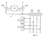
図4を参照すると、第2の実施形態に基づく装置と関連する制御システムは、ただ1つの接触圧力センサの代わりに4つの接触圧力センサ34がある点を除き、第1の実施形態に基づく装置の制御システムと、同様である。スリーブの各セルと関連する1つの圧力センサ34がある。図5a〜図5cを参照すると、この実施形態の装置のポンプ及び弁配置32は、マイクロプロセッサ28により制御される、6個の弁36及び1個のポンプ38を、含んでいる。ポンプ38は、吸入口I及び吐出口Oを有しており、また、吸入弁36P1及び吐出弁36P2と共に、流体供給ラインF内の空気圧を制御する。他の弁は、各セルと関連し、且つ、セルと流体供給ラインFとの間の空気の流れを制御するように構成された、セル弁36Cである。ポンプ弁36P1、36P2は、それぞれ、ポンプ吸入口又はポンプ吐出口に接続されたポートに加えて、大気に接続されたポートと、供給ラインFに接続されたポートと、を有している。ポンプ弁36P1は、ポンプ吸入口Iを、供給ラインF又は大気に、接続できる。ポンプ弁36P2は、ポンプ吐出口Oを、供給ラインF又は大気に、接続できる。マイクロプロセッサ28は、任意の1つ以上のセルを選択的に膨張又は収縮させるために、ポンプを使用することができるように、ポンプ及び弁に、命令を出すことができる。これは、ポンプ弁36P1、36P2を選択的に作動させて、流体供給ラインFへの又は流体供給ラインFからの、空気の流れの方向を制御することにより、ならびに、選択的に開けられたり又は閉じられたりするセル弁36Cを制御して、個々のセルへの及び個々のセルからの、空気の流れを許可することにより、達成される。各セルにおいて、圧力センサ34は、スリーブの表面上に位置付けられた接触圧力センサである。
Referring to FIG. 4, the control system associated with the apparatus according to the second embodiment is an apparatus according to the first embodiment, except that there are four
ポンプ38は、不可逆型であり、その吸入口Iから吐出口Oの方向に空気を送るように、作動する。図5aを参照すると、セルから空気を吸い出すことが要求されるとき、ポンプ吸入弁36P1は、マイクロプロセッサ28により、ポンプ吸入口Iを流体ラインFに接続するように構成されており、ポンプ吐出弁36P2は、ポンプ吐出口を大気に接続するように構成されている。弁36P1、36P2のこの動作は、ポンプ及び弁配置の中の空気を、図5aの矢印で示した方向に、流れさせる。したがって、空気は、セルから吸い出される。セル弁36Cの各々は、マイクロプロセッサ28からの命令に従って、個別に作動でき、空気を、他のセルから吸い出すことなく、1つ以上のセルから吸い出すことができる。
The
図5bを参照すると、セルに空気を送り込むことが要求されるとき、第1のポンプ弁36P1は、ポンプ吸入口Iを大気に接続するように構成され、第2のポンプ弁36P2は、ポンプ吐出口Oを供給ラインFに接続するように構成されている。その結果、ポンプの動作は、空気に、図5bに示した矢印の方向の流れを引き起こし、すなわち、空気は、セル22に向かって、送り込まれる。前と同様に、セル弁36Cは、マイクロプロセッサ28により個別に作動でき、任意の1つ以上のセルに、選択的に、空気を入れることができる。
Referring to FIG. 5b, when it is required to pump air into the cell, the first pump valve 36P1 is configured to connect the pump inlet I to the atmosphere and the second pump valve 36P2 is pumped out. The outlet O is configured to be connected to the supply line F. As a result, the operation of the pump causes the air to flow in the direction of the arrow shown in FIG. 5b, i.e., air is pumped towards the
図5cを参照すると、例えば、セルが連続圧力モード用に十分に空気を入れられた後で、セルが所望の圧力であるとき、ポンプ弁36P1と36P2の両方は、ポンプを大気に接続し、供給ラインF内の流体が、大気圧になるように、構成されている。ポンプは作動せず、セルの中の空気圧は変化しない。 Referring to FIG. 5c, for example, after the cell is fully inflated for continuous pressure mode, when the cell is at the desired pressure, both pump valves 36P1 and 36P2 connect the pump to the atmosphere, The fluid in the supply line F is configured to be atmospheric pressure. The pump does not operate and the air pressure in the cell does not change.
第2の実施形態の装置は、第1の実施形態に対して先に説明されたモードとは異なるモードで、選択的に作動できる。また、装置は、先に説明されたのと同じモードで、作動できる。その異なるモードでは、セルの各々が、例えば脚部の下端から上方に、順番に膨張する間、間欠的空気圧迫法を提供するように、装置を使用することができる。遵守データ、すなわち、装置の使用に関するデータは、プロセッサ28により収集され、メモリ30内に保存されることができる。利用者入力26を用いて、医療従事者は、メモリ30内に保存された収集データを、ディスプレイ21上に表示することを、要求できる。この実施形態では、ディスプレイ21は、コントローラの一部ではない。その代わりに、コントローラ・ユニットは、赤外線通信を介して、リモート表示画面(図示せず)と通信できる。表示データは、特定のモード、例えば、連続定圧モード又は間欠空気圧迫モードで、及び、特定の圧力で、手足を取り囲んだ状態で、各セルが膨張していた期間に関するデータを含む。また、表示データは、患者が、医療従事者による最後の訪問から、例えば、最後の週、2週間以内、の設定時間の中で、圧迫装置を使用した回数に関するデータを、含むことができる。また、データは、圧迫装置が患者により使用される実際の日時に関するデータを、含むことができる。また、表示データは、分析することができ、患者による遵守が良いか悪いかを示すために提供された表示にできる。それを超えていれば遵守が良く、それを下回れば遵守が悪い使用の設定しきい値があってもよい。患者が利用できる表示データは、医療従事者が利用できる表示データとは異なってもよく、医療従事者は、利用者入力を用いてパスワードを入力することで、詳しい情報にアクセスできてもよい。
The apparatus of the second embodiment can be selectively operated in a mode different from that previously described for the first embodiment. The device can also operate in the same mode as previously described. In that different mode, the device can be used to provide intermittent pneumatic compression while each of the cells in turn expands in turn, eg, from the lower end of the leg. Compliance data, i.e., data regarding device usage, may be collected by the
利用者入力26を用いて、医療従事者は、メモリ内に保存されたデータの一部又はすべてをリセットすることが可能である。これは、例えば、医療従事者が患者を訪れる訪問と訪問の間に、好ましい場合がある。医療従事者は、メモリ30内に保存されたデータが消去できる前に、利用者入力26を用いてパスワードを入力することを要求されるかもしれない。また、メモリ30は、最後のリセットの日付のデータを保存できる。したがって、例えば、患者がメモリをリセットすると、その日付が記録され、次の訪問で、医療従事者は、リセットの日付及びリセットのときから収集されたデータを、示される。
Using the
標準的な又は予想される膨張時間の範囲が、メモリ30に保存される。したがって、手足上の所定の位置にない状態でスリーブ2が膨張するとき、マイクロプロセッサ28は、圧力センサ34から収集されたデータを、メモリ30内に保存されたデータと比較することにより、これを認識するであろう。例えば、所定の圧力値に達するまでの時間を測定することができ、それが予想範囲内にないとき、マイクロプロセッサ28は、スリーブが手足上の所定の位置にないことを認識し、ポンプ及び弁配置32によって、スリーブを膨張させるのを止めさせ、代わりにスリーブを収縮させる。また、スリーブ2が手足上の所定の位置にないときにセンサ34により収集されたデータは、破棄することができる。したがって、マイクロプロセッサは、スリーブが膨張しているとき、スリーブが患者の手足上の所定の位置にあるかどうかを、判断できる。これは、装置の使用に関して収集され且つ保存されたデータが、装置が所定の位置にあるときの装置の正しい使用を正確に反映でき、装置が患者の所定の位置にないときのスリーブの膨張の影響を受けないようにできることを、保証する。
A standard or expected range of inflation times is stored in the
同様に、マイクロプロセッサ28は、ポンプ及び弁配置がスリーブ2を膨らませようとしているにもかかわらず、1つ以上の圧力センサ34で測定された圧力が、それに対応して高まっていないとき、そのことを認識できる。この状況では、マイクロプロセッサ28は、スリーブ2が穴を有していることを認識し、1つ以上の前記セル22に穴があることを利用者に知らせるために、ディスプレイ21上に、適当なエラー・メッセージを表示できる。
Similarly, the
本発明は、そのいくつかの好ましい実施形態に関して図示され且つ説明されているが、本発明の範囲を逸脱することなく、本発明の形態及び詳細に対する様々な変更、省略、及び追加が行われうる。例えば、使用に関するデータは、PINコードの入力を必要とせずに、任意の利用者が利用できてもよい。しかしながら、情報を消去する前に、PINコードの入力が、依然として必要であってもよい。 While the invention has been illustrated and described with respect to several preferred embodiments thereof, various modifications, omissions, and additions to the form and details of the invention may be made without departing from the scope of the invention. . For example, data relating to use may be available to any user without requiring the input of a PIN code. However, it may still be necessary to enter a PIN code before erasing the information.
間欠的空気圧迫モードは、第1の実施形態の装置と実質的に同一の装置を用いて、選択的に利用できてもよい。また、前記センサ又は各センサは、接触センサ、圧力センサ、又は、他の任意の適当な種類のセンサ、であってもよい。1つ以上のセンサが提供される場合には、異なる種類のセンサの組み合わせが用いられてもよい。例えば、第2の実施形態の接触圧力センサを、セルとその対応する弁36との間のラインに位置付けられた空気圧センサで、置き換えてもよい。センサを、コントローラ・ユニット8内に設置してもよい。
The intermittent pneumatic compression mode may be selectively available using a device that is substantially the same as the device of the first embodiment. The sensor or each sensor may be a contact sensor, a pressure sensor, or any other suitable type of sensor. If more than one sensor is provided, a combination of different types of sensors may be used. For example, the contact pressure sensor of the second embodiment may be replaced with a pneumatic sensor located in the line between the cell and its corresponding
コントローラ・ユニット8は、利用者入力26を有していなくてもよい。その代わりに、システムは、例えば、PC又は他の制御演算装置と通信(例えば、赤外線)しているときに、そのキーボードなどからの入力を、受信してもよい。
The controller unit 8 may not have the
Claims (18)
手足を取り囲むように構成された膨張可能なスリーブ(2)と、
スリーブ(2)に取り付けられ、スリーブに流体を送出するように構成された、導管(10)と、
装置内の流体の流れを制御するように構成された、制御システムと、
装置の使用時間に関して収集されたデータを保存するように構成されたメモリ(30)と、を備えており、
スリーブ(2)が手足を取り囲む所定の位置にあるかどうかを検出するように構成されており、
収集されたデータが、スリーブ(2)が手足を取り囲む所定の位置にあるかどうかの検出に依存している、
ことを特徴とする、圧迫装置。A compression device for a patient's limb,
An inflatable sleeve (2) configured to surround the limb;
A conduit (10) attached to the sleeve (2) and configured to deliver fluid to the sleeve;
A control system configured to control the flow of fluid in the device;
A memory (30) configured to store data collected regarding the usage time of the device,
Configured to detect whether the sleeve (2) is in a predetermined position surrounding the limb;
The collected data is dependent on detection of whether the sleeve (2) is in place surrounding the limb,
A compression device characterized by that.
Applications Claiming Priority (3)
| Application Number | Priority Date | Filing Date | Title |
|---|---|---|---|
| GB0515040.4 | 2005-07-21 | ||
| GBGB0515040.4A GB0515040D0 (en) | 2005-07-21 | 2005-07-21 | Compression device for the limb |
| PCT/GB2006/002738 WO2007010278A1 (en) | 2005-07-21 | 2006-07-20 | Compression device for a limb |
Publications (3)
| Publication Number | Publication Date |
|---|---|
| JP2009501594A JP2009501594A (en) | 2009-01-22 |
| JP2009501594A5 JP2009501594A5 (en) | 2009-09-03 |
| JP5031743B2 true JP5031743B2 (en) | 2012-09-26 |
Family
ID=34976355
Family Applications (1)
| Application Number | Title | Priority Date | Filing Date |
|---|---|---|---|
| JP2008522064A Expired - Fee Related JP5031743B2 (en) | 2005-07-21 | 2006-07-20 | Limb compression device |
Country Status (15)
| Country | Link |
|---|---|
| US (1) | US7909786B2 (en) |
| EP (1) | EP1919430B1 (en) |
| JP (1) | JP5031743B2 (en) |
| CN (1) | CN101267793B (en) |
| AT (1) | ATE521322T1 (en) |
| AU (1) | AU2006271380B2 (en) |
| CA (1) | CA2616145C (en) |
| DK (1) | DK1919430T3 (en) |
| ES (1) | ES2369935T3 (en) |
| GB (1) | GB0515040D0 (en) |
| MX (1) | MX2008000813A (en) |
| NZ (1) | NZ565187A (en) |
| PT (1) | PT1919430E (en) |
| TW (1) | TWI392489B (en) |
| WO (1) | WO2007010278A1 (en) |
Families Citing this family (84)
| Publication number | Priority date | Publication date | Assignee | Title |
|---|---|---|---|---|
| TWI376221B (en) | 2005-06-08 | 2012-11-11 | Convatec Technologies Inc | Compression device for the foot |
| US9642759B2 (en) | 2007-04-13 | 2017-05-09 | Stryker Corporation | Patient support with universal energy supply system |
| US8182437B2 (en) | 2007-05-08 | 2012-05-22 | Wright Therapy Products, Inc. | Pneumatic compression therapy system and methods of using same |
| US8388557B2 (en) | 2007-06-20 | 2013-03-05 | Remo Moomiaie-Qajar | Portable compression device |
| US20090204037A1 (en) * | 2008-02-12 | 2009-08-13 | Sundaram Ravikumar | Compression Apparatus for Applying Intermittent Pressure to the Leg |
| US8384551B2 (en) * | 2008-05-28 | 2013-02-26 | MedHab, LLC | Sensor device and method for monitoring physical stresses placed on a user |
| US7969315B1 (en) | 2008-05-28 | 2011-06-28 | MedHab, LLC | Sensor device and method for monitoring physical stresses placed upon a user |
| US20100042028A1 (en) * | 2008-08-14 | 2010-02-18 | Albahealth, LLC | Foot wrap with inflatable bladder |
| US8535253B2 (en) | 2008-09-30 | 2013-09-17 | Covidien Lp | Tubeless compression device |
| US8177734B2 (en) * | 2008-09-30 | 2012-05-15 | Tyco Healthcare Group Lp | Portable controller unit for a compression device |
| US20110245743A1 (en) * | 2008-12-02 | 2011-10-06 | Medical Minds LLC | Compression device and control system for applying pressure to a limb of a living being |
| US8162869B2 (en) * | 2009-07-10 | 2012-04-24 | Tyco Healthcare Group Lp | Hybrid compression garmet |
| US8752220B2 (en) * | 2009-07-10 | 2014-06-17 | Hill-Rom Services, Inc. | Systems for patient support, monitoring and treatment |
| US8257289B2 (en) * | 2010-02-03 | 2012-09-04 | Tyco Healthcare Group Lp | Fitting of compression garment |
| US8394043B2 (en) * | 2010-02-12 | 2013-03-12 | Covidien Lp | Compression garment assembly |
| US20120065561A1 (en) * | 2010-09-03 | 2012-03-15 | Epoch Medical Innovations, Inc. | Device, system, and method for the treatment, prevention and diagnosis of chronic venous insufficiency, deep vein thrombosis, lymphedema and other circulatory conditions |
| US8753300B2 (en) | 2010-09-29 | 2014-06-17 | Covidien Lp | Compression garment apparatus having baseline pressure |
| US8758282B2 (en) | 2010-09-29 | 2014-06-24 | Covidien Lp | Compression garment apparatus having support bladder |
| US20120083712A1 (en) * | 2010-09-30 | 2012-04-05 | Tyco Healthcare Group Lp | Monitoring Compliance Using Venous Refill Detection |
| US10004946B2 (en) | 2011-03-24 | 2018-06-26 | MedHab, LLC | System and method for monitoring power applied to a bicycle |
| US9453772B2 (en) | 2011-03-24 | 2016-09-27 | MedHab, LLC | Method of manufacturing a sensor insole |
| US10813825B2 (en) * | 2011-06-14 | 2020-10-27 | Portable Therapeutix, LLC | Compression device |
| US9114054B2 (en) | 2011-07-24 | 2015-08-25 | Oakwell Distribution, Inc. | System for monitoring the use of medical devices |
| US9125787B2 (en) | 2011-09-30 | 2015-09-08 | Covidien Lp | Compression garment having a foam layer |
| US9737454B2 (en) | 2012-03-02 | 2017-08-22 | Hill-Rom Services, Inc. | Sequential compression therapy compliance monitoring systems and methods |
| US20130231596A1 (en) * | 2012-03-02 | 2013-09-05 | David W. Hornbach | Sequential compression therapy compliance monitoring systems & methods |
| JP6392744B2 (en) | 2012-03-12 | 2018-09-19 | ライト セラピー プロダクツ、インク. | Compression therapy device having multiple simultaneous activation chambers |
| US9889063B2 (en) * | 2012-06-11 | 2018-02-13 | Wright Therapy Products, Inc. | Methods and systems for determining use compliance of a compression therapy device |
| DE102012013534B3 (en) | 2012-07-05 | 2013-09-19 | Tobias Sokolowski | Apparatus for repetitive nerve stimulation for the degradation of adipose tissue by means of inductive magnetic fields |
| JP2015528335A (en) | 2012-08-18 | 2015-09-28 | ライト セラピー プロダクツ、インク. | Method for determining body part dimensions as part of a pressure therapy procedure |
| US9872812B2 (en) | 2012-09-28 | 2018-01-23 | Kpr U.S., Llc | Residual pressure control in a compression device |
| US9402779B2 (en) | 2013-03-11 | 2016-08-02 | Covidien Lp | Compression garment with perspiration relief |
| US10058475B2 (en) * | 2013-03-15 | 2018-08-28 | Innovamed Health, LLC | Portable intermittent pneumatic compression system |
| CN103239340B (en) * | 2013-05-16 | 2015-01-07 | 四川旭康医疗电器有限公司 | Feeling rehabilitation training system and achieving method thereof |
| GB2514587A (en) * | 2013-05-30 | 2014-12-03 | Vibrant Medical Ltd | Treatment of peripheral arterial disease and other conditions, and apparatus therefor |
| US9615992B2 (en) * | 2013-07-30 | 2017-04-11 | Lockheed Martin Corporation | System and method for supplementing circulation in a body |
| US20150057585A1 (en) * | 2013-08-20 | 2015-02-26 | Covidien Lp | Compression device having compliance tracking |
| JP6041774B2 (en) * | 2013-09-06 | 2016-12-14 | 日東工器株式会社 | Edema severity meter |
| US9295605B2 (en) | 2013-12-02 | 2016-03-29 | Wright Therapy Products, Inc. | Methods and systems for auto-calibration of a pneumatic compression device |
| US10470967B2 (en) | 2014-01-20 | 2019-11-12 | Tactile Systems Technology, Inc. | Bespoke compression therapy device |
| US10292894B2 (en) | 2014-02-11 | 2019-05-21 | Tactile Systems Technology, Inc. | Compression therapy device and compression therapy protocols |
| JP6012015B2 (en) * | 2014-03-13 | 2016-10-25 | パナソニックIpマネジメント株式会社 | AIR MASSAGE DEVICE AND ITS AUXILIARY |
| US20150297100A1 (en) * | 2014-04-18 | 2015-10-22 | Hilario Castillo | Vital Socks |
| US9687404B2 (en) | 2014-08-26 | 2017-06-27 | Elwha Llc | Garment system including at least one muscle or joint activity sensor and at least one actuator responsive to the sensor and related methods |
| US20160120734A1 (en) * | 2014-10-30 | 2016-05-05 | Elwha Llc | Garment system including at least one sensor and at least one actuator responsive to the sensor and related methods |
| US20160120733A1 (en) * | 2014-10-30 | 2016-05-05 | Elwha Llc | Garment system including at least one sensor and at least one actuator responsive to the sensor and related methods |
| US10456604B2 (en) | 2014-08-26 | 2019-10-29 | Elwha Llc | Garment system including at least one therapeutic stimulation delivery device and related methods |
| US11638676B2 (en) * | 2014-08-26 | 2023-05-02 | Ventrk, Llc | Garment system including at least one sensor and at least one actuator responsive to the sensor and related methods |
| US10232165B2 (en) | 2015-01-29 | 2019-03-19 | Elwha Llc | Garment system including at least one sensor and at least one actuator responsive to the sensor and related methods |
| US10668305B2 (en) | 2014-08-26 | 2020-06-02 | Elwha Llc | Garment system including at least one therapeutic stimulation delivery device and related methods |
| US11491342B2 (en) | 2015-07-01 | 2022-11-08 | Btl Medical Solutions A.S. | Magnetic stimulation methods and devices for therapeutic treatments |
| US20180001107A1 (en) | 2016-07-01 | 2018-01-04 | Btl Holdings Limited | Aesthetic method of biological structure treatment by magnetic field |
| US11266850B2 (en) | 2015-07-01 | 2022-03-08 | Btl Healthcare Technologies A.S. | High power time varying magnetic field therapy |
| US10695575B1 (en) | 2016-05-10 | 2020-06-30 | Btl Medical Technologies S.R.O. | Aesthetic method of biological structure treatment by magnetic field |
| IL311576A (en) | 2015-10-09 | 2024-05-01 | Kpr Us Llc | compression garment compliance |
| US11253717B2 (en) | 2015-10-29 | 2022-02-22 | Btl Healthcare Technologies A.S. | Aesthetic method of biological structure treatment by magnetic field |
| US10667984B2 (en) | 2015-12-18 | 2020-06-02 | Stryker Corporation | Systems and methods for operating patient therapy devices |
| US11141105B2 (en) * | 2016-03-11 | 2021-10-12 | Respiratory Technology Corporation | Long-term therapeutic pressure applicator and real-time monitoring system |
| CA3021991A1 (en) | 2016-04-27 | 2017-11-02 | Radial Medical, Inc. | Adaptive compression therapy systems and methods |
| US11464993B2 (en) | 2016-05-03 | 2022-10-11 | Btl Healthcare Technologies A.S. | Device including RF source of energy and vacuum system |
| US11247039B2 (en) | 2016-05-03 | 2022-02-15 | Btl Healthcare Technologies A.S. | Device including RF source of energy and vacuum system |
| US11534619B2 (en) | 2016-05-10 | 2022-12-27 | Btl Medical Solutions A.S. | Aesthetic method of biological structure treatment by magnetic field |
| US10583287B2 (en) | 2016-05-23 | 2020-03-10 | Btl Medical Technologies S.R.O. | Systems and methods for tissue treatment |
| CN108143608A (en) * | 2016-06-08 | 2018-06-12 | 武汉佰起科技有限公司 | One kind is smoked to wash instrument and its application method |
| US10556122B1 (en) | 2016-07-01 | 2020-02-11 | Btl Medical Technologies S.R.O. | Aesthetic method of biological structure treatment by magnetic field |
| US11504293B2 (en) * | 2016-11-08 | 2022-11-22 | Lear Corporation | Seat assembly having massage bladders with reduced pressure sensor count |
| US20180229048A1 (en) * | 2017-02-15 | 2018-08-16 | Btl Holdings Limited | Method and device for body fluid stimulation |
| US11410771B2 (en) | 2017-06-01 | 2022-08-09 | Stryker Corporation | Patient care devices with open communication |
| USD870297S1 (en) | 2017-09-28 | 2019-12-17 | Tactile Systems Technology, Inc. | Trunk garment |
| US10434033B2 (en) | 2017-11-01 | 2019-10-08 | Vena Group, LLC | Portable, reusable, and disposable intermittent pneumatic compression system |
| WO2019090338A1 (en) | 2017-11-06 | 2019-05-09 | Tactile Systems Technology, Inc. | Compression garment systems |
| US20210069056A1 (en) * | 2018-05-31 | 2021-03-11 | Neuraltide | Pressure application method |
| FR3081704B1 (en) * | 2018-05-31 | 2023-11-17 | Neuraltide | PRESSURE APPLICATION CLOTHING |
| US10893998B2 (en) | 2018-10-10 | 2021-01-19 | Inova Labs Inc. | Compression apparatus and systems for circulatory disorders |
| US10646233B1 (en) | 2018-11-28 | 2020-05-12 | Jay Dean Everett | Device, system and method for intermittent displacement of blood to mitigate peripheral nerve neuropathy |
| KR102192619B1 (en) * | 2018-12-07 | 2020-12-17 | 순천향대학교 산학협력단 | Compression Stocking Equipped With Aircell |
| EP3721939B1 (en) | 2019-04-11 | 2022-07-06 | BTL Healthcare Technologies a.s. | Device for aesthetic treatment of biological structures by radiofrequency and magnetic energy |
| KR200498115Y1 (en) | 2020-05-04 | 2024-07-03 | 비티엘 헬쓰케어 테크놀로지스 에이.에스. | Device for cosmetic procedures on patients |
| US11878167B2 (en) | 2020-05-04 | 2024-01-23 | Btl Healthcare Technologies A.S. | Device and method for unattended treatment of a patient |
| JP2023548095A (en) * | 2020-11-05 | 2023-11-15 | ナショナル ユニバーシティー ホスピタル (シンガポール) ピーティーイー リミテッド | Mobile limb compression system |
| MX2024004340A (en) * | 2021-10-11 | 2024-06-05 | Arjo Ip Holding Ab | A system, method and garment for monitoring and controlling fluid pressure during compression therapy. |
| EP4415812A1 (en) | 2021-10-13 | 2024-08-21 | BTL Medical Solutions a.s. | Devices for aesthetic treatment of biological structures by radiofrequency and magnetic energy |
| US11896816B2 (en) | 2021-11-03 | 2024-02-13 | Btl Healthcare Technologies A.S. | Device and method for unattended treatment of a patient |
| USD971267S1 (en) | 2022-01-03 | 2022-11-29 | Therabody, Inc. | Controller for pneumatic compression device |
Family Cites Families (14)
| Publication number | Priority date | Publication date | Assignee | Title |
|---|---|---|---|---|
| US4396010A (en) * | 1980-06-30 | 1983-08-02 | The Kendall Company | Sequential compression device |
| US5807075A (en) * | 1993-11-23 | 1998-09-15 | Sarcos, Inc. | Disposable ambulatory microprocessor controlled volumetric pump |
| JPH07250873A (en) * | 1994-03-14 | 1995-10-03 | Tec Corp | Blood circulation accelerator |
| US6786879B1 (en) * | 1994-04-05 | 2004-09-07 | Kci Licensing, Inc. | Gradient sequential compression system for preventing deep vein thrombosis |
| US5575762A (en) * | 1994-04-05 | 1996-11-19 | Beiersdorf-Jobst, Inc. | Gradient sequential compression system and method for reducing the occurrence of deep vein thrombosis |
| US5591200A (en) * | 1994-06-17 | 1997-01-07 | World, Inc. | Method and apparatus for applying pressure to a body limb for treating edema |
| US5843007A (en) * | 1996-04-29 | 1998-12-01 | Mcewen; James Allen | Apparatus and method for periodically applying a pressure waveform to a limb |
| US6387065B1 (en) * | 1996-09-30 | 2002-05-14 | Kinetic Concepts, Inc. | Remote controllable medical pumping apparatus |
| US6494852B1 (en) * | 1998-03-11 | 2002-12-17 | Medical Compression Systems (Dbn) Ltd. | Portable ambulant pneumatic compression system |
| JP2000334011A (en) * | 1999-05-27 | 2000-12-05 | Family Kk | Massaging machine and storage medium storing massaging information |
| WO2002055005A1 (en) * | 2001-01-12 | 2002-07-18 | Midtown Technology Ltd. | Inflatable massage garment |
| JP2002065780A (en) * | 2000-08-28 | 2002-03-05 | Matsushita Electric Works Ltd | Massage machine |
| US6926617B2 (en) * | 2002-03-15 | 2005-08-09 | Sri Sports Limited | Golf club shaft |
| US20040111048A1 (en) * | 2002-12-04 | 2004-06-10 | Jensen Jeffrey L. | Compression device for treatment of chronic venous insufficiency |
-
2005
- 2005-07-21 GB GBGB0515040.4A patent/GB0515040D0/en not_active Ceased
-
2006
- 2006-07-20 WO PCT/GB2006/002738 patent/WO2007010278A1/en active Application Filing
- 2006-07-20 TW TW095126877A patent/TWI392489B/en not_active IP Right Cessation
- 2006-07-20 CA CA2616145A patent/CA2616145C/en active Active
- 2006-07-20 AT AT06765067T patent/ATE521322T1/en active
- 2006-07-20 PT PT06765067T patent/PT1919430E/en unknown
- 2006-07-20 MX MX2008000813A patent/MX2008000813A/en active IP Right Grant
- 2006-07-20 AU AU2006271380A patent/AU2006271380B2/en not_active Ceased
- 2006-07-20 CN CN2006800340740A patent/CN101267793B/en not_active Expired - Fee Related
- 2006-07-20 NZ NZ565187A patent/NZ565187A/en not_active IP Right Cessation
- 2006-07-20 EP EP06765067A patent/EP1919430B1/en active Active
- 2006-07-20 JP JP2008522064A patent/JP5031743B2/en not_active Expired - Fee Related
- 2006-07-20 ES ES06765067T patent/ES2369935T3/en active Active
- 2006-07-20 DK DK06765067.1T patent/DK1919430T3/en active
- 2006-07-21 US US11/459,036 patent/US7909786B2/en active Active
Also Published As
| Publication number | Publication date |
|---|---|
| CA2616145C (en) | 2014-07-08 |
| AU2006271380A1 (en) | 2007-01-25 |
| TWI392489B (en) | 2013-04-11 |
| CA2616145A1 (en) | 2007-01-25 |
| NZ565187A (en) | 2011-01-28 |
| DK1919430T3 (en) | 2011-10-17 |
| GB0515040D0 (en) | 2005-08-31 |
| WO2007010278A1 (en) | 2007-01-25 |
| ES2369935T3 (en) | 2011-12-09 |
| MX2008000813A (en) | 2008-03-18 |
| EP1919430B1 (en) | 2011-08-24 |
| AU2006271380B2 (en) | 2011-09-22 |
| TW200716074A (en) | 2007-05-01 |
| US7909786B2 (en) | 2011-03-22 |
| JP2009501594A (en) | 2009-01-22 |
| PT1919430E (en) | 2011-10-19 |
| US20070049853A1 (en) | 2007-03-01 |
| CN101267793B (en) | 2012-07-04 |
| CN101267793A (en) | 2008-09-17 |
| ATE521322T1 (en) | 2011-09-15 |
| EP1919430A1 (en) | 2008-05-14 |
Similar Documents
| Publication | Publication Date | Title |
|---|---|---|
| JP5031743B2 (en) | Limb compression device | |
| JP5081165B2 (en) | Pressurized medical device | |
| JP6316831B2 (en) | Monitoring system used for pressure therapy | |
| US20180092781A1 (en) | Telemedical wearable sensing system for management of chronic venous disorders | |
| EP3102172B1 (en) | A portable compression device | |
| JP6352282B2 (en) | Pressure device monitoring system | |
| US20120065561A1 (en) | Device, system, and method for the treatment, prevention and diagnosis of chronic venous insufficiency, deep vein thrombosis, lymphedema and other circulatory conditions | |
| MX2008009134A (en) | Pressurised medical device |
Legal Events
| Date | Code | Title | Description |
|---|---|---|---|
| A521 | Request for written amendment filed |
Free format text: JAPANESE INTERMEDIATE CODE: A523 Effective date: 20090717 |
|
| A621 | Written request for application examination |
Free format text: JAPANESE INTERMEDIATE CODE: A621 Effective date: 20090717 |
|
| RD04 | Notification of resignation of power of attorney |
Free format text: JAPANESE INTERMEDIATE CODE: A7424 Effective date: 20091228 |
|
| A711 | Notification of change in applicant |
Free format text: JAPANESE INTERMEDIATE CODE: A711 Effective date: 20110523 |
|
| A977 | Report on retrieval |
Free format text: JAPANESE INTERMEDIATE CODE: A971007 Effective date: 20110811 |
|
| A131 | Notification of reasons for refusal |
Free format text: JAPANESE INTERMEDIATE CODE: A131 Effective date: 20110823 |
|
| A521 | Request for written amendment filed |
Free format text: JAPANESE INTERMEDIATE CODE: A523 Effective date: 20111118 |
|
| TRDD | Decision of grant or rejection written | ||
| A01 | Written decision to grant a patent or to grant a registration (utility model) |
Free format text: JAPANESE INTERMEDIATE CODE: A01 Effective date: 20120529 |
|
| A01 | Written decision to grant a patent or to grant a registration (utility model) |
Free format text: JAPANESE INTERMEDIATE CODE: A01 |
|
| A61 | First payment of annual fees (during grant procedure) |
Free format text: JAPANESE INTERMEDIATE CODE: A61 Effective date: 20120627 |
|
| R150 | Certificate of patent or registration of utility model |
Ref document number: 5031743 Country of ref document: JP Free format text: JAPANESE INTERMEDIATE CODE: R150 Free format text: JAPANESE INTERMEDIATE CODE: R150 |
|
| FPAY | Renewal fee payment (event date is renewal date of database) |
Free format text: PAYMENT UNTIL: 20150706 Year of fee payment: 3 |
|
| S111 | Request for change of ownership or part of ownership |
Free format text: JAPANESE INTERMEDIATE CODE: R313113 |
|
| R350 | Written notification of registration of transfer |
Free format text: JAPANESE INTERMEDIATE CODE: R350 |
|
| R250 | Receipt of annual fees |
Free format text: JAPANESE INTERMEDIATE CODE: R250 |
|
| R250 | Receipt of annual fees |
Free format text: JAPANESE INTERMEDIATE CODE: R250 |
|
| R250 | Receipt of annual fees |
Free format text: JAPANESE INTERMEDIATE CODE: R250 |
|
| R250 | Receipt of annual fees |
Free format text: JAPANESE INTERMEDIATE CODE: R250 |
|
| R250 | Receipt of annual fees |
Free format text: JAPANESE INTERMEDIATE CODE: R250 |
|
| LAPS | Cancellation because of no payment of annual fees |