JP5021253B2 - Rotation angle detector - Google Patents
Rotation angle detector Download PDFInfo
- Publication number
- JP5021253B2 JP5021253B2 JP2006227680A JP2006227680A JP5021253B2 JP 5021253 B2 JP5021253 B2 JP 5021253B2 JP 2006227680 A JP2006227680 A JP 2006227680A JP 2006227680 A JP2006227680 A JP 2006227680A JP 5021253 B2 JP5021253 B2 JP 5021253B2
- Authority
- JP
- Japan
- Prior art keywords
- rotation angle
- magnetic
- detection
- rotation
- magnetic detection
- Prior art date
- Legal status (The legal status is an assumption and is not a legal conclusion. Google has not performed a legal analysis and makes no representation as to the accuracy of the status listed.)
- Expired - Fee Related
Links
Images
Classifications
-
- G—PHYSICS
- G01—MEASURING; TESTING
- G01D—MEASURING NOT SPECIALLY ADAPTED FOR A SPECIFIC VARIABLE; ARRANGEMENTS FOR MEASURING TWO OR MORE VARIABLES NOT COVERED IN A SINGLE OTHER SUBCLASS; TARIFF METERING APPARATUS; MEASURING OR TESTING NOT OTHERWISE PROVIDED FOR
- G01D5/00—Mechanical means for transferring the output of a sensing member; Means for converting the output of a sensing member to another variable where the form or nature of the sensing member does not constrain the means for converting; Transducers not specially adapted for a specific variable
- G01D5/12—Mechanical means for transferring the output of a sensing member; Means for converting the output of a sensing member to another variable where the form or nature of the sensing member does not constrain the means for converting; Transducers not specially adapted for a specific variable using electric or magnetic means
- G01D5/14—Mechanical means for transferring the output of a sensing member; Means for converting the output of a sensing member to another variable where the form or nature of the sensing member does not constrain the means for converting; Transducers not specially adapted for a specific variable using electric or magnetic means influencing the magnitude of a current or voltage
- G01D5/142—Mechanical means for transferring the output of a sensing member; Means for converting the output of a sensing member to another variable where the form or nature of the sensing member does not constrain the means for converting; Transducers not specially adapted for a specific variable using electric or magnetic means influencing the magnitude of a current or voltage using Hall-effect devices
- G01D5/145—Mechanical means for transferring the output of a sensing member; Means for converting the output of a sensing member to another variable where the form or nature of the sensing member does not constrain the means for converting; Transducers not specially adapted for a specific variable using electric or magnetic means influencing the magnitude of a current or voltage using Hall-effect devices influenced by the relative movement between the Hall device and magnetic fields
Landscapes
- Physics & Mathematics (AREA)
- General Physics & Mathematics (AREA)
- Transmission And Conversion Of Sensor Element Output (AREA)
- Measurement Of Length, Angles, Or The Like Using Electric Or Magnetic Means (AREA)
Description
本発明は、検出対象の回転角度を検出する回転角度検出装置に関するものである。 The present invention relates to a rotation angle detection device that detects a rotation angle of a detection target.
従来、検出対象とともに磁石が回転し、磁石の回転により生じる磁界の変化を磁気検出素子で検出し、磁気検出素子の出力信号に基づいて三角関数演算により検出対象の回転角度を検出する回転角度検出装置が知られている(例えば、特許文献1参照)。
しかしながら、特許文献1のように、回転する磁石の円周付近に回転方向に離れて磁気検出素子を設置して磁気検出手段を構成すると、回転角度検出装置全体の体格が大型化するという問題がある。
Conventionally, a rotation angle detection in which a magnet rotates with a detection target, a change in a magnetic field caused by the rotation of the magnet is detected by a magnetic detection element, and a rotation angle of the detection target is detected by trigonometric calculation based on an output signal of the magnetic detection element An apparatus is known (see, for example, Patent Document 1).
However, as in
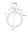
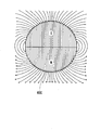
また、回転方向に離れて磁気検出素子を設置する構成では、組付時、または組付後においては振動等により各磁気検出素子と磁石との距離にばらつきが生じやすい。ここで、図19に示すように、永久磁石等で形成される磁界発生手段400の周囲の磁束密度は全周において均一ではないため、回転方向に離れて設置された磁気検出素子と磁界発生手段400との距離にばらつきが生じると、各磁気検出素子が検出する磁束密度の変化率が異なり、出力信号の変化率も異なってくる。また、通常、磁気検出素子は温度に応じて出力信号値が変化する温度特性を有するので、回転方向に離れて磁気検出素子を設置する構成では、回転方向に温度分布が生じると、設置箇所の温度に応じて磁気検出素子の出力信号の変化率が異なってくる。変化率が異なる検出信号から三角関数演算により回転角度を算出すると、算出した回転角度の誤差が大きくなるという問題がある。 Further, in the configuration in which the magnetic detection elements are installed apart from each other in the rotation direction, the distance between each magnetic detection element and the magnet is likely to vary due to vibration or the like during or after assembly. Here, as shown in FIG. 19, since the magnetic flux density around the magnetic field generating means 400 formed of a permanent magnet or the like is not uniform over the entire circumference, the magnetic detection elements and the magnetic field generating means installed apart in the rotation direction. When the distance from 400 varies, the change rate of the magnetic flux density detected by each magnetic detection element is different, and the change rate of the output signal is also different. In addition, since the magnetic detection element usually has a temperature characteristic in which the output signal value changes according to the temperature, in the configuration in which the magnetic detection element is installed away from the rotation direction, if temperature distribution occurs in the rotation direction, The rate of change of the output signal of the magnetic detection element varies depending on the temperature. When the rotation angle is calculated by trigonometric function calculation from detection signals having different rates of change, there is a problem that an error in the calculated rotation angle increases.
そこで、図16に示すように、磁界発生手段400の回転方向の一箇所に磁気検出手段410を設置し、回転角度検出装置を小型化することが考えられる。磁界発生手段400または磁気検出手段410の一方が、検出対象と連動して回転する。磁気検出手段410には、磁気検出素子412として、例えば2個のホール素子が使用される。図16では、2個の磁気検出素子412のうち一方の磁気検出素子412の感磁面413を回転軸402の回転軸線404と直交する仮想直線420に沿って設置し、他方の磁気検出素子412の感磁面413を一方の感磁面413に対して90°に設置している。
Therefore, as shown in FIG. 16, it is conceivable to install the magnetic detection means 410 at one place in the rotation direction of the magnetic field generation means 400 to downsize the rotation angle detection device. One of the magnetic field generation means 400 or the magnetic detection means 410 rotates in conjunction with the detection target. In the magnetic detection means 410, for example, two Hall elements are used as the
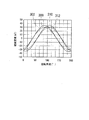
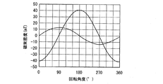
図16に示すように、2個の磁気検出素子412を設置すると、図17に示すように、回転角度に応じて2個の磁気検出素子412が検出する磁束密度の位相差は90°になる。磁気検出素子412は磁束密度に応じた信号を出力するので、磁気検出素子412の出力信号の位相差も90°になる。
しかしながら、図16に示すように、一方の磁気検出素子412の感磁面413を回転軸402の回転軸線404と直交する仮想直線420に沿って設置し、他方の磁気検出素子412の感磁面413を一方の感磁面413に対して90°を形成するように設置すると、前述したように、磁界発生手段400の周囲の磁束密度は全周において均一ではないため、図17に示すように、各磁気検出素子412の感磁面413が検出する磁束密度の大きさに差が生じる。つまり、2個の磁気検出素子412の出力信号の振幅が異なる。検出対象の回転角度に応じて変化する磁束密度を磁気検出素子412で検出し、その出力信号から三角関数演算により回転角度を算出するためには、2個の磁気検出素子412の出力信号の振幅を等しくする必要がある。
When two
However, as shown in FIG. 16, the
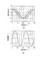
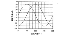
そこで、図18に示すように、振幅の小さい方の出力を増幅して2個の出力信号の振幅を合わせ、算出する回転角度の誤差を低減することが考えられる。
しかしながら、出力信号を増幅すると、増幅前の元信号に含まれていた誤差が増幅されるので、結果として算出する回転角度の誤差を低減することができない。また、振幅の小さい出力信号をAD変換器で読み込むとビット誤差が大きくなるので、回転角度の誤差を低減することができない。
Therefore, as shown in FIG. 18, it is conceivable to amplify the output with the smaller amplitude and match the amplitudes of the two output signals to reduce the error of the calculated rotation angle.
However, when the output signal is amplified, the error included in the original signal before amplification is amplified, and as a result, the calculated rotation angle error cannot be reduced. In addition, when an output signal having a small amplitude is read by an AD converter, a bit error increases, so that the rotation angle error cannot be reduced.
本発明は上記問題を解決するためになされたものであり、小型で回転角度の検出精度が高い回転角度検出装置を提供することを目的とする。 The present invention has been made to solve the above problems, and an object of the present invention is to provide a rotation angle detection device that is small and has high detection accuracy of rotation angle.
請求項1から8に記載の発明によると、磁界発生手段に対して相対回転自在に回転方向の1箇所に第1磁気検出素子および第2磁気検出素子を有する磁気検出手段を設置している。したがって、磁気検出手段を小型化し、結果として回転角度検出装置を小型化できる。
さらに、回転方向の1箇所に第1磁気検出素子および第2磁気検出素子を設置しているので、温度等の磁気検出素子の動作環境が両磁気検出素子において同程度に変化する。また、磁気検出手段と磁界発生手段との距離がずれても、2個の磁気検出素子と磁界発生手段との距離は同程度にずれる。その結果、動作環境が変化したり、磁気検出手段と磁界発生手段との距離がずれても、2個の磁気検出素子の出力は同程度に変化する。したがって、動作環境が変化したり、磁気検出手段と磁界発生手段との距離がずれても、2個の磁気検出素子の出力信号に基づいて検出対象の回転角度を高精度に検出できる。
According to the first to eighth aspects of the present invention, the magnetic detection means having the first magnetic detection element and the second magnetic detection element is provided at one place in the rotation direction so as to be rotatable relative to the magnetic field generation means. Therefore, the magnetic detection means can be downsized, and as a result, the rotation angle detection device can be downsized.
Furthermore, since the first magnetic detection element and the second magnetic detection element are installed at one place in the rotation direction, the operating environment of the magnetic detection element such as temperature changes to the same extent in both magnetic detection elements. Further, even if the distance between the magnetic detection means and the magnetic field generation means is deviated, the distance between the two magnetic detection elements and the magnetic field generation means is shifted to the same extent. As a result, even if the operating environment changes or the distance between the magnetic detection means and the magnetic field generation means shifts, the outputs of the two magnetic detection elements change to the same extent. Therefore, even if the operating environment changes or the distance between the magnetic detection means and the magnetic field generation means is shifted, the rotation angle of the detection target can be detected with high accuracy based on the output signals of the two magnetic detection elements.
ここで、図16に示す2個の磁気検出素子412の感磁面413が検出する磁束密度の最大値をそれぞれA、B、磁界発生手段400の回転角度θに応じて2個の磁気検出素子412が検出する磁束密度をそれぞれB0x、B0yとすると、B0x、B0yは次式(1)、(2)で示される。2個の磁気検出素子412は、検出磁束密度B0x、B0yの値に係数を乗じた信号を出力するので、検出磁束密度B0x、B0yを出力信号とみなしてよい。以下、Bkx、Bky(k=0、1、2・・・)を出力ということもある。
B0x=A×sinθ ・・・(1)
B0y=−B×cosθ ・・・(2)
Here, the maximum value of the magnetic flux density detected by the
B 0 x = A × sin θ (1)
B 0 y = −B × cos θ (2)
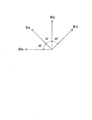
次に、請求項1から8に記載の発明において、回転軸線と直交する仮想平面上に、第1磁気検出素子の感磁面の延びる方向と第2磁気検出素子の感磁面の延びる方向とが90°を形成して設置され、回転軸線と直交する仮想直線に対し両感磁面の延びる方向がそれぞれ45°傾斜するように設置された磁気検出素子が、磁気検出手段に対して相対回転する磁界発生手段の回転角度θに応じて検出する磁束密度をそれぞれB1x、B1yとすると(図15参照)、ベクトルの合成により、B1x、B1yは次式(3)、(4)で示される。
Next, in the invention described in
B1x=B0x×cos45+B0y×sin45 ・・・(3)
B1y=−B0x×sin45+B0y×cos45 ・・・(4)
式(1)〜(4)より、
B1x=B0x/(21/2)+B0y/(21/2)
=A×sinθ/(21/2)−B×cosθ/(21/2)
=((A2+B2)/2)1/2×sin(θ+β) ・・・(5)
B1y=−B0x/(21/2)+B0y/(21/2)
=−A×sinθ/(21/2)−B×cosθ/(21/2)
=((A2+B2)/2)1/2×sin(θ+γ) ・・・(6)
B 1 x = B 0 x ×
B 1 y = −B 0 x × sin 45 + B 0 y × cos 45 (4)
From formulas (1) to (4),
B 1 x = B 0 x / (2 1/2 ) + B 0 y / (2 1/2 )
= A × sin θ / (2 1/2 ) −B × cos θ / (2 1/2 )
= ((A 2 + B 2 ) / 2) 1/2 × sin (θ + β) (5)
B 1 y = −B 0 x / (2 1/2 ) + B 0 y / (2 1/2 )
= −A × sin θ / (2 1/2 ) −B × cos θ / (2 1/2 )
= ((A 2 + B 2 ) / 2) 1/2 × sin (θ + γ) (6)
式(5)、(6)から分かるように、前述した図16に示す構成において、2個の磁気検出素子412の検出する磁束密度の最大値A、Bが異なっても、請求項1から8に記載の発明においては、2個の磁気検出素子が検出する磁束密度の最大値は((A2+B2)/2)1/2となり、等しい。つまり、2個の磁気検出素子の出力信号の振幅は等しくなる。
これにより、振幅の異なる2個の磁気検出素子の出力のうち、一方の出力値を他方の出力値に合わせて増幅する処理が不要になるので、容易に、かつ高精度に検出対象の回転角度を検出できる。
Equation (5), as can be seen from (6), in the configuration shown in FIG. 16 described above, two maximum value A of the detected magnetic flux density of the
This eliminates the need to amplify the output value of one of the two magnetic detection elements having different amplitudes in accordance with the output value of the other, so that the rotation angle of the detection target can be easily and accurately detected. Can be detected.
請求項2に記載の発明によると、磁界発生手段は円板状または円筒状の永久磁石で形成されているので、磁気検出素子に対して永久磁石が相対回転するときに、回転角度に応じて磁気検出素子が出力する検出信号の波形を正弦波形により近づけることができる。したがって、2個の磁気検出素子の出力信号から、回転角度を高精度に検出できる。 According to the second aspect of the present invention, the magnetic field generating means is formed of a disk-shaped or cylindrical permanent magnet. Therefore, when the permanent magnet rotates relative to the magnetic detection element, the magnetic field generating means depends on the rotation angle. The waveform of the detection signal output from the magnetic detection element can be made closer to a sine waveform. Therefore, the rotation angle can be detected with high accuracy from the output signals of the two magnetic detection elements.
請求項3に記載の発明によると、2個の磁気検出素子は1チップの半導体で形成されているので、例えば2個の磁気検出素子をそれぞれ別チップで形成するよりも、半導体製造工程において磁気検出素子が形成する角度を高精度に90°にすることができる。さらに、2個の磁気検出素子の動作環境が一致する。したがって、回転角度を高精度に検出できる。 According to the third aspect of the present invention, since the two magnetic detection elements are formed of one chip of semiconductor, for example, two magnetic detection elements are magnetically formed in the semiconductor manufacturing process rather than formed of separate chips. The angle formed by the detection element can be 90 ° with high accuracy. Furthermore, the operating environments of the two magnetic detection elements match. Therefore, the rotation angle can be detected with high accuracy.
ここで、式(5)から、
sinβ=−B/(A2+B2)1/2 ・・・(7)
cosβ=A/(A2+B2)1/2 ・・・(8)
よって、
β=cos-1(A/(A2+B2)1/2) ・・・(9)
また、式(6)から、
sinγ=−B/(A2+B2)1/2 ・・・(10)
cosγ=−A/(A2+B2)1/2 ・・・(11)
よって、
γ=cos-1(−A/(A2+B2)1/2)
=180°−β ・・・(12)
したがって、2個の磁気検出素子の出力信号の位相差(β−γ)は、次式(13)で表される。
(β−γ)=β−(180°−β)=2×(β−90°)・・・(13)
Here, from equation (5)
sin β = −B / (A 2 + B 2 ) 1/2 (7)
cos β = A / (A 2 + B 2 ) 1/2 (8)
Therefore,
β = cos −1 (A / (A 2 + B 2 ) 1/2 ) (9)
From equation (6),
sin γ = −B / (A 2 + B 2 ) 1/2 (10)
cosγ = −A / (A 2 + B 2 ) 1/2 (11)
Therefore,
γ = cos −1 (−A / (A 2 + B 2 ) 1/2 )
= 180 ° -β (12)
Therefore, the phase difference (β−γ) of the output signals of the two magnetic detection elements is expressed by the following equation (13).
(Β−γ) = β− (180 ° −β) = 2 × (β−90 °) (13)
請求項1に記載の発明では、2個の磁気検出素子を感磁面が90°を形成するように設置しているが、式(13)から分かるように、2個の磁気検出素子の出力信号の位相差(β−γ)は90°からずれている。そして、式(9)、(12)から分かるように、位相差(β−γ)は、図16に示す構成において、2個の磁気検出素子412の検出する磁束密度の最大値A、Bに応じて変化する。
In the first aspect of the present invention, the two magnetic detection elements are installed so that the magnetosensitive surface forms 90 °, but as can be seen from the equation (13), the outputs of the two magnetic detection elements. The phase difference (β−γ) of the signal is shifted from 90 °. As can be seen from the equations (9) and (12), the phase difference (β−γ) is equal to the maximum values A and B of the magnetic flux density detected by the two
ここで、図16に示す構成において、磁気検出手段410の位置が磁界発生手段400に対して径方向にずれると、2個の磁気検出素子412の検出する磁束密度の最大値A、Bが変化する。したがって、請求項1に記載の発明においては、磁気検出手段、つまり磁気検出素子の位置が磁界発生手段に対して径方向にずれると、式(5)、(6)、(9)、(12)のA、Bの値が変化することにより、磁気検出素子の出力の振幅および位相が変化する。ただし、請求項1に記載の発明では、式(5)、(6)から分かるように、磁気検出素子の位置が磁界発生手段に対して径方向にずれて2個の磁気検出素子の出力の振幅が変化しても、両方の振幅は定数倍されて等しくなる。したがって、振幅が変化しても回転角度の誤差は生じない。しかし、請求項1に記載の発明では、式(13)から分かるように、2個の磁気検出素子の出力の位相が変化すると、出力の位相差が変化する。位相差が変化すると、三角関数演算により算出する回転角度に誤差が生じる。ここで、位相差の変化により生じる回転角度の誤差は、磁気検出素子の出力の位相差が90°のときに最も小さいことが分かっている。
Here, in the configuration shown in FIG. 16, when the position of the magnetic detection means 410 is displaced in the radial direction with respect to the magnetic field generation means 400, the maximum values A and B of the magnetic flux density detected by the two
そこで、請求項5に記載の発明では、両出力信号の位相差を90°に補正して検出対象の回転角度を算出手段が算出するので、磁気検出素子の位置が磁界発生手段に対して径方向にずれても、算出手段が算出する回転角度の誤差を極力小さくすることができる。
また、請求項5に記載の発明では、両出力信号の位相差を90°に補正することにより、両出力信号がsin、cosの関係になる。したがって、位相差を90°に補正した両出力信号の値をBx、By、磁界発生手段の回転角度をθとすると、例えば、θ=tan-1(Bx/By)の簡単な三角関数演算により、検出対象の回転角度を容易に算出できる。
Therefore, in the invention according to claim 5 , since the calculation means calculates the rotation angle of the detection target by correcting the phase difference between the two output signals to 90 °, the position of the magnetic detection element is a diameter relative to the magnetic field generation means. Even if the direction is deviated, the error of the rotation angle calculated by the calculating means can be minimized.
In the fifth aspect of the invention, by correcting the phase difference between the two output signals to 90 °, the two output signals have a relationship of sin and cos. Accordingly, assuming that the values of both output signals with the phase difference corrected to 90 ° are Bx and By and the rotation angle of the magnetic field generating means is θ, for example, by a simple trigonometric function calculation of θ = tan −1 (Bx / By) The rotation angle of the detection target can be easily calculated.
本発明の複数の実施の形態を図に基づいて説明する。
(第1実施形態)
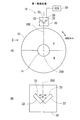
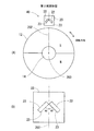
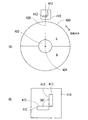
本発明の第1実施形態による回転角度検出装置を図1に示す。回転角度検出装置10は、例えばクランクシャフトや車輪等の検出対象の回転角度を検出する装置である。回転角度検出装置10は、円板状の永久磁石12、角度センサとしてのホールIC20、および電子制御装置(ECU;Electronic Control Unit)30からなる。磁界発生手段としての永久磁石12は、回転軸14を中心として検出対象と連動して回転する。永久磁石12は円板状に形成されており、径方向に向けて着磁されている。永久磁石12は、図19に示す磁界を形成する。
A plurality of embodiments of the present invention will be described with reference to the drawings.
(First embodiment)
A rotation angle detection device according to a first embodiment of the present invention is shown in FIG. The rotation
磁気検出手段としてのホールIC20は、永久磁石12の回転方向の1箇所に設置されている。これにより、回転角度検出装置10を小型化できる。ホールIC20は、2個のホール素子22を1チップの半導体として実装した角度センサである。ホールIC20からは、2個のホール素子22の検出信号がそれぞれECU30に出力される。回転角度検出装置10では、2個のホール素子22とECU30とを別部品にしてもよいし、1個の半導体として1チップで構成してもよい。図1および図2に示すように、ホールIC20は永久磁石12よりも径方向外側に、永久磁石12の外周面と向き合って設置されている。
The
2個のホール素子22は、回転軸14の回転軸線200と直交する仮想平面上において、回転軸線200と直交する仮想直線202を挟んで両側に、仮想直線202に対して感磁面23がそれぞれ45°の角度で傾斜し、2個の感磁面23の交差角度が90°になるように設置されている。
算出手段であるECU30は、図示しないCPU、ROM、RAM、EEPROM等から構成されている。ECU30は、EEPROMまたはROMに記憶されている角度算出プログラムを実行することにより、ホールIC20の出力信号から、検出対象の回転角度を算出する。
The two
The
次に、回転角度検出装置10による、検出対象の回転角度の算出方法について説明する。
(算出方法1)
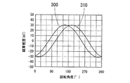
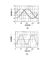
前述したように、式(5)、(6)から、2個のホール素子22が検出する磁束密度300、310の振幅は、図3に示すように等しい。その最大振幅を((A2+B2)/2)1/2=Vとすると、式(5)、(6)、(12)から、
B1x=V×sin(θ+β) ・・・(20)
B1y=V×sin(θ+γ)
=V×sin(θ+(180°−β))
=−V×sin(θ−β) ・・・(21)
ここで、
B1x+B1y=V×sin(θ+β)−V×sin(θ−β)
=2V×cosθsinβ ・・・(22)
B1x−B1y=V×sin(θ+β)+V×sin(θ−β)
=2V×sinθcosβ ・・・(23)
Next, a method for calculating the rotation angle of the detection target by the rotation
(Calculation method 1)
As described above, the amplitudes of the
B 1 x = V × sin (θ + β) (20)
B 1 y = V × sin (θ + γ)
= V × sin (θ + (180 ° −β))
= −V × sin (θ−β) (21)
here,
B 1 x + B 1 y = V × sin (θ + β) −V × sin (θ−β)
= 2V × cos θ sin β (22)
B 1 x−B 1 y = V × sin (θ + β) + V × sin (θ−β)
= 2V × sin θ cos β (23)
式(22)、(23)より、
(B1x−B1y)/(B1x+B1y)=sinθcosβ/cosθsinβ
=tanθcotβ
したがって、
θ=tan-1(tanβ×(B1x−B1y)/(B1x+B1y))・・・(24)
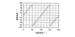
式(24)から、図1に示す第1実施形態において、2個のホール素子22の一方の出力B1xの位相角度βと、2個のホール素子22の出力B1xおよびB1yから、三角関数演算により、図4に示すように検出対象の回転角度θを算出できる。
From equations (22) and (23),
(B 1 x−B 1 y) / (B 1 x + B 1 y) = sin θ cos β / cos θ sin β
= Tan θcotβ
Therefore,
θ = tan −1 (tan β × (B 1 x−B 1 y) / (B 1 x + B 1 y)) (24)
From the equation (24), in the first embodiment shown in FIG. 1, the phase angle β of one output B 1 x of the two
(算出方法2)
予め、図16に示すようにホール素子を設置したときに、各ホール素子が検出する磁束密度の最大値A、Bを計測しておけば、式(7)、(8)よりtanβ=(−B/A)であるから、式(24)より、
θ=tan-1(−(B/A)×(B1x−B1y)/(B1x+B1y))
=−tan-1((B/A)×(B1x−B1y)/(B1x+B1y))
・・・(30)
である。したがって、図16に示すようにホール素子を設置したときに、各ホール素子が検出する磁束密度の最大値A、Bを予め計測しておけば、検出磁束密度の最大値A、Bと、図1に示すように設置した本実施形態の2個のホール素子22の出力B1xおよびB1yとから、三角関数演算により検出対象の回転角度θを算出できる。最大値A、Bは、実際には、図16に示すようにホール素子を設置したときの各ホール素子の出力の最大値である。
(Calculation method 2)
If the maximum values A and B of the magnetic flux density detected by each Hall element are measured in advance when the Hall element is installed as shown in FIG. 16, tan β = (− B / A), from equation (24),
θ = tan −1 (− (B / A) × (B 1 x−B 1 y) / (B 1 x + B 1 y))
= −tan −1 ((B / A) × (B 1 x−B 1 y) / (B 1 x + B 1 y))
... (30)
It is. Accordingly, when the Hall elements are installed as shown in FIG. 16, if the maximum values A and B of the magnetic flux density detected by each Hall element are measured in advance, the maximum values A and B of the detected magnetic flux density From the outputs B 1 x and B 1 y of the two
(算出方法3)
tanβ=cot(90°−β)であるから、式(24)より、
θ=tan-1(cot(90°−β)×(B1x−B1y)/(B1x+B1y))
・・・(40)
ここで、2個のホール素子22の出力の位相差をαとすると、
α=β−γ=β−(180°−β)=−(180°−2β)
したがって、
−α/2=90°−β ・・・(41)
よって、式(40)、(41)から、
θ=tan-1(cot(−α/2)×(B1x−B1y)/(B1x+B1y))
=−tan-1(cot(α/2)×(B1x−B1y)/(B1x+B1y))
・・・(42)
(Calculation method 3)
Since tan β = cot (90 ° −β), from the equation (24),
θ = tan −1 (cot (90 ° −β) × (B 1 x−B 1 y) / (B 1 x + B 1 y))
... (40)
Here, if the phase difference between the outputs of the two
α = β−γ = β− (180 ° −β) = − (180 ° −2β)
Therefore,
-Α / 2 = 90 ° -β (41)
Therefore, from the equations (40) and (41),
θ = tan −1 (cot (−α / 2) × (B 1 x−B 1 y) / (B 1 x + B 1 y))
= −tan −1 (cot (α / 2) × (B 1 x−B 1 y) / (B 1 x + B 1 y))
... (42)
したがって、2個のホール素子22の位相差αと、2個のホール素子22の出力B1xおよびB1yとから、三角関数演算により検出対象の回転角度θを算出できる。
以上説明した算出方法1、2、3は、いずれか一つが選択されて検出対象の回転角度が算出される。次に説明する算出方法4は、算出方法1、2、3、と組み合わせて回転角度が算出される。
Therefore, from the phase difference α between the two
Any one of the
(算出方法4)
ホールIC20の位置が永久磁石12に対して径方向にずれると、前述したように、ホール素子22の出力信号300、310の振幅、ならびに出力信号300、310の位相が変化する(図5参照)。ただし、ホール素子22の出力信号300、310の振幅は共に定数倍された出力信号302、312になる。したがって、振幅の変化は角度の算出結果には影響しない。しかし、ホールIC20の位置が永久磁石12に対して径方向にずれると、図5に示すように、ホール素子22の出力信号300、310の位相が変化し、位相変化後の出力信号302と出力信号312との位相差が変化する。このように、2個のホール素子22の出力信号の位相差が変化すると、2個のホール素子22の出力信号から算出する回転角度に誤差が生じる。
(Calculation method 4)
When the position of the
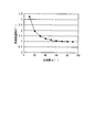
ここで、2個のホール素子22の出力信号の位相差と、算出した回転角度の誤差との関係を図8に示す。位相差が90°に向けて大きくなるにしたがい、角度誤差が小さくなることが分かる。例えば、90°よりも位相差が小さいときの検出信号と、この検出信号から算出した回転角度の誤差との関係を図6に示し、位相差が90°のときの検出信号と、この検出信号から算出した回転角度の誤差との関係を図7に示す。図6の(A)、図7の(A)において、実線は位置ずれ前の検出信号を示し、点線は位置ずれ後の検出信号を示している。位相差が90°の方が、角度誤差が小さくなっている。
FIG. 8 shows the relationship between the phase difference between the output signals of the two
そこで、2個のホール素子22の出力信号の値を元に、マップを参照し、2個のホール素子22の出力信号の値を、位相差が90°になるように補正する。そして、位相差を90°に補正した後のホール素子22の出力信号から回転角度を算出する。位相差を90°に補正された2個のホール素子22の出力は、振幅の等しいsinとcosとの関係になる。したがって、位相差を90°に補正した両出力信号の値をBx、Byとすると、例えば、θ=tan-1(Bx/By)の簡単な三角関数演算により、検出対象の回転角度を容易に算出できる。
このように、ホールIC20の位置が永久磁石12に対して径方向にずれても、2個のホール素子22の出力の位相差を90°に補正することにより、算出される回転角度の誤差を極力小さくし、かつ検出対象の回転角度を容易に算出できる。
Therefore, based on the values of the output signals of the two
Thus, even if the position of the
(温度特性補償)
次に、第1実施形態において、温度特性を考慮したときの回転角度の算出について説明する。
式(1)、(2)において、温度特性を考慮したときの検出磁束密度をそれぞれB2x、B2y、式(5)、(6)において度特性を考慮したときの検出磁束密度をそれぞれB3x、B3y、式(5)、(6)において温度特性を考慮したときの2個のホール素子22の出力信号の位相角度をβ3、γ3、ホール素子22の温度特性係数をk(t)とすると、B2x、B2y、B3x、B3yは次式(50)、(51)、(52)、(53)で示される。
(Temperature characteristic compensation)
Next, calculation of the rotation angle when temperature characteristics are taken into account in the first embodiment will be described.
In equations (1) and (2), the detected magnetic flux density when the temperature characteristic is taken into consideration is B 2 x and B 2 y, respectively, and the detected magnetic flux density when the degree characteristic is taken into consideration in equations (5) and (6), respectively. The phase angles of the output signals of the two
B2x=k(t)×B0x=A×k(t)×sinθ ・・・(50)
B2y=k(t)×B0y=−B×k(t)×cosθ・・・(51)
B3x=B2x/(21/2)+B2y/(21/2)
=A×k(t)×sinθ/(21/2)−B×k(t)×cosθ/(21/2)
=k(t)×((A2+B2)/2)1/2×sin(θ+β3)
・・・(52)
B3y=−B2x/(21/2)+B2y/(21/2)
=−A×k(t)×sinθ/(21/2)−B×k(t)×cosθ/(21/2)
=k(t)×((A2+B2)/2)1/2×sin(θ+γ3)
・・・(53)
B 2 x = k (t) × B 0 x = A × k (t) × sin θ (50)
B 2 y = k (t) × B 0 y = −B × k (t) × cos θ (51)
B 3 x = B 2 x / (2 1/2 ) + B 2 y / (2 1/2 )
= A × k (t) × sin θ / (2 1/2 ) −B × k (t) × cos θ / (2 1/2 )
= K (t) × ((A 2 + B 2 ) / 2) 1/2 × sin (θ + β 3 )
... (52)
B 3 y = −B 2 x / (2 1/2 ) + B 2 y / (2 1/2 )
= −A × k (t) × sin θ / (2 1/2 ) −B × k (t) × cos θ / (2 1/2 )
= K (t) × ((A 2 + B 2 ) / 2) 1/2 × sin (θ + γ 3 )
... (53)
ここで、式(52)から、
cosβ3=A/(A2+B2)1/2
よって、式(8)、(9)より、
β3=cos-1(A/(A2+B2)1/2)=β・・・(54)
また、式(53)から、
cosγ3=−A/(A2+B2)1/2
よって、式(11)、(12)より
γ3=cos-1(−A/(A2+B2)1/2)
=γ=180°−β ・・・(55)
Here, from equation (52)
cos β 3 = A / (A 2 + B 2 ) 1/2
Therefore, from the equations (8) and (9),
β 3 = cos −1 (A / (A 2 + B 2 ) 1/2 ) = β (54)
From the equation (53),
cos γ 3 = −A / (A 2 + B 2 ) 1/2
Therefore, from formulas (11) and (12), γ 3 = cos −1 (−A / (A 2 + B 2 ) 1/2 )
= Γ = 180 ° −β (55)
式(52)〜(55)から、温度変化が生じても、2個のホール素子22の出力信号の位相角度および位相差は変化せず、振幅がk(t)倍されることが分かる。そして、式(5)、(6)、(52)〜(55)から、
B3x=k(t)×((A2+B2)/2)1/2×sin(θ+β3)
=k(t)×B1x ・・・(56)
B3y=k(t)×((A2+B2)/2)1/2×sin(θ+γ3)
=k(t)×B1y ・・・(57)
From equations (52) to (55), it can be seen that the phase angle and phase difference of the output signals of the two
B 3 x = k (t) × ((A 2 + B 2 ) / 2) 1/2 × sin (θ + β 3 )
= K (t) × B 1 x (56)
B 3 y = k (t) × ((A 2 + B 2 ) / 2) 1/2 × sin (θ + γ 3 )
= K (t) × B 1 y (57)
式(24)において、B1xをB3xに、B1yをB3yに置き換え、式(56)、(57)を代入すると、
θ=tan-1(tanβ×(B3x−B3y)/(B3x+B3y))
=tan-1(tanβ×k(t)×(B1x−B1y)/(k(t)×(B1x+B1y)))
=tan-1(tanβ×(B1x−B1y)/(B1x+B1y))・・・(58)
つまり、本実施形態では、周囲温度が変化しても、回転角度の算出結果は温度変化の影響を受けない。したがって、周囲温度の変化に関わらず、回転角度を高精度に検出できる。
In equation (24), when B 1 x is replaced with B 3 x, B 1 y is replaced with B 3 y, and equations (56) and (57) are substituted,
θ = tan −1 (tan β × (B 3 x−B 3 y) / (B 3 x + B 3 y))
= Tan −1 (tan β × k (t) × (B 1 x−B 1 y) / (k (t) × (B 1 x + B 1 y)))
= Tan −1 (tan β × (B 1 x−B 1 y) / (B 1 x + B 1 y)) (58)
That is, in this embodiment, even if the ambient temperature changes, the calculation result of the rotation angle is not affected by the temperature change. Therefore, the rotation angle can be detected with high accuracy regardless of the change in the ambient temperature.
(第2〜第7実施形態)
本発明の第2〜第7実施形態を図9〜図14の各図に示す。図9〜図14においては、ECU30を省略している。尚、既述の実施形態と実質的に同一構成部分には同一符号を付す。
第2〜第7実施形態においても、2個のホール素子22の感磁面23は、回転軸14の回転軸線200と直交する仮想平面上において、交差角度が90°になるように設置されている。また、回転軸線200と直交する仮想直線202に対して、感磁面23はそれぞれ45°の角度で傾斜している。
(Second to seventh embodiments)
Second to seventh embodiments of the present invention are shown in FIGS. 9 to 14. 9 to 14, the
Also in the second to seventh embodiments, the magnetosensitive surfaces 23 of the two
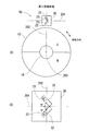
図9に示す第2実施形態の回転角度検出装置40では、第1実施形態と同様に、2個のホール素子22は、回転軸14の回転軸線200と直交する仮想平面上において、回転軸線200と直交する仮想直線202を挟んで両側に、仮想直線202に対して感磁面23がそれぞれ45°の角度で傾斜し、2個の感磁面23の交差角度が90°になるように設置されている。ただし、回転角度検出装置40は、図1に示す第1実施形態のホール1C20を180°回転して設置されている。つまり、回転角度検出装置40では、2個のホール素子22の感磁面23は、仮想直線202を挟んで両側にそれぞれ45°の角度で傾斜して90°の交差角度を形成し、永久磁石12に向けて開いている。
In the rotation
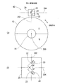
図10、図11に示す第3、第4実施形態の回転角度検出装置50、60では、2個のホール素子22は、回転軸14の回転軸線200と直交する仮想平面上において、回転軸線200と直交する仮想直線202対して感磁面23がそれぞれ45°の角度で傾斜し、2個の感磁面23の交差角度が90°になるように設置されている。ただし、回転角度検出装置50、60は、図1に示す第1実施形態のホール1C20を左右に90°回転して設置されている。つまり、回転角度検出装置50、60では、2個のホール素子22の感磁面23は、円板状の永久磁石12の接線に沿った仮想直線204を挟んで両側に、仮想直線204に対してそれぞれ45°の角度で傾斜して90°の交差角度を形成し、永久磁石12の接線方向のいずれか一方に向けて開いている。
In the rotation
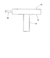
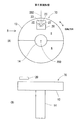
図12に示す第5実施形態の回転角度検出装置70では、ホールIC20は、永久磁石12の外周縁側の端面上に設置されている。
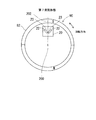
図13に示す第6実施形態の回転角度検出装置80では、磁界発生手段としての永久磁石82は、円環状または円筒状に形成されている。ホールIC20は、永久磁石82の径方向外側に、永久磁石82の軸方向長さの範囲内で永久磁石82と向き合って設置されている。
図14に示す第7実施形態の回転角度検出装置90では、ホールIC20は、永久磁石82の径方向内側に、永久磁石82の軸方向長さの範囲内で永久磁石82と向き合って設置されている。
In the rotation
In the
In the rotation
(他の実施形態)
以上説明した上記実施形態では、磁界発生手段としての永久磁石が検出対象と連動して回転した。これに対し、磁気検出手段としてのホールICが検出対象と連動して回転してもよい。
上記実施形態において、磁界発生手段として、電磁石等を使用してもよい。
上記実施形態では、2個のホール素子を1チップの半導体として製造しホールIC20を形成した。これに対し、2個のホール素子を別チップの半導体として製造し、感磁面が90°を形成し、回転軸線と直交する仮想直線に対して感磁面が45°の角度で傾斜するように2個のホール素子を設置してもよい。
(Other embodiments)
In the embodiment described above, the permanent magnet as the magnetic field generating means rotates in conjunction with the detection target. On the other hand, the Hall IC as the magnetic detection means may rotate in conjunction with the detection target.
In the above embodiment, an electromagnet or the like may be used as the magnetic field generating means.
In the above embodiment, the
このように、本発明は、上記複数の実施形態に限定されるものではなく、その要旨を逸脱しない範囲で種々の実施形態に適用可能である。 As in this, the present invention is not limited to the above plurality of embodiments are applicable to various embodiments within a scope not departing from the gist.
10、40、50、60、70、80、90:回転角度検出装置、12、82:永久磁石(磁界発生手段)、20:ホールIC、(磁気検出手段)、22:ホール素子(磁気検出素子)、30:ECU(算出手段)、200:回転軸線、202:仮想直線 10, 40, 50, 60, 70, 80, 90: Rotation angle detection device, 12, 82: Permanent magnet (magnetic field generation means), 20: Hall IC, (magnetic detection means), 22: Hall element (magnetic detection element) ), 30: ECU (calculation means), 200: rotation axis, 202: virtual straight line
Claims (8)
磁界発生手段と、
前記検出対象の回転に伴って前記磁界発生手段に対して相対回転する磁気検出手段と、
を備え、
前記磁気検出手段は、前記磁界発生手段に対して相対回転自在に回転方向の1箇所に設置され、前記磁界発生手段に対して前記磁気検出手段が相対回転することにより生じる磁界の変化に応じた信号を出力する第1磁気検出素子および第2磁気検出素子を有し、
前記両磁気検出素子はホール素子であって、相対回転の回転軸線と直交する仮想平面上に、前記第1磁気検出素子の感磁面の延びる方向と前記第2磁気検出素子の感磁面の延びる方向とが90°を形成して設置され、前記回転軸線と直交する仮想直線に対し、前記両感磁面の延びる方向はそれぞれ45°傾斜している回転角度検出装置。 In the rotation angle detection device for detecting the rotation angle of the detection target,
Magnetic field generating means;
Magnetic detection means that rotates relative to the magnetic field generation means as the detection object rotates;
With
The magnetic detection means is installed at one place in the rotation direction so as to be rotatable relative to the magnetic field generation means, and responds to a change in magnetic field generated by relative rotation of the magnetic detection means with respect to the magnetic field generation means. A first magnetic detection element and a second magnetic detection element for outputting a signal;
The two magnetic detection elements are Hall elements, and on the virtual plane orthogonal to the rotation axis of relative rotation, the direction in which the magnetic sensing surface of the first magnetic detection element extends and the magnetic sensing surface of the second magnetic detection element are The rotation angle detecting device is installed so that the extending direction forms 90 °, and the extending directions of the two magnetosensitive surfaces are inclined by 45 ° with respect to a virtual straight line orthogonal to the rotation axis.
Priority Applications (3)
| Application Number | Priority Date | Filing Date | Title |
|---|---|---|---|
| JP2006227680A JP5021253B2 (en) | 2006-08-24 | 2006-08-24 | Rotation angle detector |
| US11/878,523 US7663360B2 (en) | 2006-08-24 | 2007-07-25 | Rotation angle detecting device |
| DE102007000440A DE102007000440A1 (en) | 2006-08-24 | 2007-08-13 | Rotational angle detection device comprises magnetic element for producing magnetic field and magnetic sensor with pair of sensor elements for detecting change in magnetic field |
Applications Claiming Priority (1)
| Application Number | Priority Date | Filing Date | Title |
|---|---|---|---|
| JP2006227680A JP5021253B2 (en) | 2006-08-24 | 2006-08-24 | Rotation angle detector |
Publications (2)
| Publication Number | Publication Date |
|---|---|
| JP2008051638A JP2008051638A (en) | 2008-03-06 |
| JP5021253B2 true JP5021253B2 (en) | 2012-09-05 |
Family
ID=38973394
Family Applications (1)
| Application Number | Title | Priority Date | Filing Date |
|---|---|---|---|
| JP2006227680A Expired - Fee Related JP5021253B2 (en) | 2006-08-24 | 2006-08-24 | Rotation angle detector |
Country Status (3)
| Country | Link |
|---|---|
| US (1) | US7663360B2 (en) |
| JP (1) | JP5021253B2 (en) |
| DE (1) | DE102007000440A1 (en) |
Families Citing this family (22)
| Publication number | Priority date | Publication date | Assignee | Title |
|---|---|---|---|---|
| US7469604B2 (en) * | 2005-10-21 | 2008-12-30 | Stoneridge Control Devices, Inc. | Sensor system including a magnetized shaft |
| JP2009058240A (en) * | 2007-08-30 | 2009-03-19 | Denso Corp | Rotation detector |
| JP5192926B2 (en) * | 2008-06-30 | 2013-05-08 | 古河電気工業株式会社 | Rotation angle detector |
| US7830216B1 (en) * | 2008-09-23 | 2010-11-09 | Silicon Labs Sc, Inc. | Precision, temperature stable clock using a frequency-control circuit and a single oscillator |
| US10704925B2 (en) | 2009-01-12 | 2020-07-07 | Infineon Technologies Ag | Sensor and method for determining angular position including measuring magnetic field lines at a distance greater than the inner radius and less than the outer radius of a ring magnet, and at a distance greater than the outer radius or less than the inner radius |
| JP5879025B2 (en) * | 2010-03-26 | 2016-03-08 | 旭化成エレクトロニクス株式会社 | Hall element |
| JP5105263B2 (en) | 2010-03-29 | 2012-12-26 | 株式会社デンソー | Rotation angle detector |
| CN102022974B (en) * | 2010-10-29 | 2013-01-23 | 昌辉汽车电气系统(安徽)有限公司 | Calibration method of magnetic induction effect angle sensor |
| US9062989B2 (en) * | 2010-12-15 | 2015-06-23 | Nxp B.V. | Magnetic field sensor for sensing rotation a reference component about the axis of rotation that is independent of alignment between the axis of rotation and the sensors |
| DE102011008614A1 (en) * | 2010-12-30 | 2012-07-05 | Siemens Aktiengesellschaft | Determining the angular position of a rotor |
| JP5141780B2 (en) * | 2011-01-12 | 2013-02-13 | Tdk株式会社 | Rotation angle sensor |
| EP2485374B2 (en) | 2011-02-04 | 2017-03-01 | Dr. Fritz Faulhaber GmbH & Co. KG | Miniature electric motor |
| DE202011002402U1 (en) | 2011-02-04 | 2012-05-07 | Dr. Fritz Faulhaber Gmbh & Co. Kg | Electric micromotor |
| JP5692607B2 (en) * | 2012-07-05 | 2015-04-01 | 株式会社デンソー | Position detecting device and manufacturing method thereof |
| CN103915233B (en) * | 2013-01-05 | 2017-02-08 | 江苏多维科技有限公司 | Permanent magnet suitable for magnetic angle encoder |
| DE112015003432T5 (en) * | 2014-07-25 | 2017-04-27 | Mitsubishi Electric Corporation | Magnetic sensor device |
| US9933448B1 (en) | 2017-01-11 | 2018-04-03 | Infineon Technologies Ag | Stray-field robust, twist-insensitive magnetic speed sensors |
| DE102017109531B3 (en) | 2017-05-04 | 2018-07-19 | Schaeffler Technologies AG & Co. KG | Sensor arrangement and method for generating a position change signal sequence |
| JP2020153813A (en) * | 2019-03-20 | 2020-09-24 | 日本電産コパル電子株式会社 | Noncontact angle sensor |
| US11175160B2 (en) * | 2019-10-18 | 2021-11-16 | Allegro Microsystems, Llc | Magnetic field sensor and method with reduced distortion measurement in sideshaft applications |
| US11493527B2 (en) | 2020-10-21 | 2022-11-08 | Infineon Technologies Ag | Zero-gauss-magnet for differential, twist-insensitive magnetic speed sensors |
| GB2604921A (en) * | 2021-03-19 | 2022-09-21 | Oxford Instruments Nanotechnology Tools Ltd | Ultra-low temperature rotator apparatus |
Family Cites Families (10)
| Publication number | Priority date | Publication date | Assignee | Title |
|---|---|---|---|---|
| JPS6276607U (en) * | 1985-10-31 | 1987-05-16 | ||
| JPH0420812A (en) * | 1990-05-15 | 1992-01-24 | Tokai Rika Co Ltd | Rotation angle detector |
| US5644226A (en) * | 1994-03-02 | 1997-07-01 | Nippondenso Co., Ltd. | Magnetic detector having a bias magnet and magnetoresistive elements shifted away from the center of the magnet |
| JP2982638B2 (en) * | 1995-01-19 | 1999-11-29 | 株式会社デンソー | Displacement detector |
| US6326781B1 (en) * | 1999-01-11 | 2001-12-04 | Bvr Aero Precision Corp | 360 degree shaft angle sensing and remote indicating system using a two-axis magnetoresistive microcircuit |
| JP2003004412A (en) * | 2001-06-21 | 2003-01-08 | Tokai Rika Co Ltd | Rotary angle detector |
| JP2003075108A (en) | 2001-09-04 | 2003-03-12 | Asahi Kasei Corp | Rotation angle sensor |
| JP4376150B2 (en) | 2004-08-06 | 2009-12-02 | 株式会社デンソー | Rotation angle detector |
| JP4679358B2 (en) | 2005-02-03 | 2011-04-27 | 株式会社デンソー | Rotation angle detector |
| JP4519750B2 (en) | 2005-09-29 | 2010-08-04 | 株式会社日本自動車部品総合研究所 | Rotation angle detector |
-
2006
- 2006-08-24 JP JP2006227680A patent/JP5021253B2/en not_active Expired - Fee Related
-
2007
- 2007-07-25 US US11/878,523 patent/US7663360B2/en not_active Expired - Fee Related
- 2007-08-13 DE DE102007000440A patent/DE102007000440A1/en not_active Withdrawn
Also Published As
| Publication number | Publication date |
|---|---|
| JP2008051638A (en) | 2008-03-06 |
| US7663360B2 (en) | 2010-02-16 |
| US20080048651A1 (en) | 2008-02-28 |
| DE102007000440A1 (en) | 2008-02-28 |
Similar Documents
| Publication | Publication Date | Title |
|---|---|---|
| JP5021253B2 (en) | Rotation angle detector | |
| JP4519750B2 (en) | Rotation angle detector | |
| JP4470577B2 (en) | Rotation angle detector | |
| JP4858837B2 (en) | Rotation angle detector | |
| JP4729358B2 (en) | Rotation angle sensor | |
| JP5682798B2 (en) | Position detection device | |
| JP5613839B2 (en) | Method and apparatus for absolute positioning of a moving object | |
| JP4720233B2 (en) | Rotation angle detector | |
| JP5801566B2 (en) | Rotation angle detector | |
| US7339371B2 (en) | Rotation angle detector | |
| JP5818104B2 (en) | Rotation angle detector | |
| JP2005351849A (en) | Rotational angle detecting device and rotational angle detection method | |
| JP5131537B2 (en) | Angle detector | |
| JP2007263585A (en) | Rotation angle detector | |
| JP2005345153A (en) | Rotation angle detector | |
| JP2008151628A (en) | Rotation sensor | |
| JP2008082739A (en) | Rotation angle detection device and rotation control device using it | |
| JP5176208B2 (en) | Rotation angle detection method and rotation angle sensor | |
| JP5360503B2 (en) | Magnetic detection device, rotation angle detection device and stroke amount detection device using the same | |
| JP4756475B2 (en) | Magnetic rotor and rotation angle detection device | |
| JPWO2008050581A1 (en) | Rotation angle detector | |
| JP2009300262A (en) | Displacement detector | |
| JP2010038765A (en) | Rotation detector | |
| JP5692607B2 (en) | Position detecting device and manufacturing method thereof | |
| JP6455314B2 (en) | Rotation detector |
Legal Events
| Date | Code | Title | Description |
|---|---|---|---|
| A621 | Written request for application examination |
Free format text: JAPANESE INTERMEDIATE CODE: A621 Effective date: 20081015 |
|
| A977 | Report on retrieval |
Free format text: JAPANESE INTERMEDIATE CODE: A971007 Effective date: 20101122 |
|
| A131 | Notification of reasons for refusal |
Free format text: JAPANESE INTERMEDIATE CODE: A131 Effective date: 20110106 |
|
| A521 | Request for written amendment filed |
Free format text: JAPANESE INTERMEDIATE CODE: A523 Effective date: 20110218 |
|
| A131 | Notification of reasons for refusal |
Free format text: JAPANESE INTERMEDIATE CODE: A131 Effective date: 20120323 |
|
| A521 | Request for written amendment filed |
Free format text: JAPANESE INTERMEDIATE CODE: A523 Effective date: 20120508 |
|
| TRDD | Decision of grant or rejection written | ||
| A01 | Written decision to grant a patent or to grant a registration (utility model) |
Free format text: JAPANESE INTERMEDIATE CODE: A01 Effective date: 20120608 |
|
| A01 | Written decision to grant a patent or to grant a registration (utility model) |
Free format text: JAPANESE INTERMEDIATE CODE: A01 |
|
| A61 | First payment of annual fees (during grant procedure) |
Free format text: JAPANESE INTERMEDIATE CODE: A61 Effective date: 20120614 |
|
| R150 | Certificate of patent or registration of utility model |
Ref document number: 5021253 Country of ref document: JP Free format text: JAPANESE INTERMEDIATE CODE: R150 Free format text: JAPANESE INTERMEDIATE CODE: R150 |
|
| FPAY | Renewal fee payment (event date is renewal date of database) |
Free format text: PAYMENT UNTIL: 20150622 Year of fee payment: 3 |
|
| R250 | Receipt of annual fees |
Free format text: JAPANESE INTERMEDIATE CODE: R250 |
|
| R250 | Receipt of annual fees |
Free format text: JAPANESE INTERMEDIATE CODE: R250 |
|
| R250 | Receipt of annual fees |
Free format text: JAPANESE INTERMEDIATE CODE: R250 |
|
| R250 | Receipt of annual fees |
Free format text: JAPANESE INTERMEDIATE CODE: R250 |
|
| R250 | Receipt of annual fees |
Free format text: JAPANESE INTERMEDIATE CODE: R250 |
|
| R250 | Receipt of annual fees |
Free format text: JAPANESE INTERMEDIATE CODE: R250 |
|
| LAPS | Cancellation because of no payment of annual fees |