JP5020681B2 - Flexible substrate bending machine - Google Patents

Flexible substrate bending machine Download PDF

Info

Publication number
JP5020681B2
JP5020681B2 JP2007088963A JP2007088963A JP5020681B2 JP 5020681 B2 JP5020681 B2 JP 5020681B2 JP 2007088963 A JP2007088963 A JP 2007088963A JP 2007088963 A JP2007088963 A JP 2007088963A JP 5020681 B2 JP5020681 B2 JP 5020681B2
Authority
JP
Japan
Prior art keywords
bending
flexible substrate
cylinder
roller
support table
Prior art date
Legal status (The legal status is an assumption and is not a legal conclusion. Google has not performed a legal analysis and makes no representation as to the accuracy of the status listed.)
Expired - Fee Related
Application number
JP2007088963A
Other languages
Japanese (ja)
Other versions
JP2008251695A5 (en
JP2008251695A (en
Inventor
浩二 板谷
Current Assignee (The listed assignees may be inaccurate. Google has not performed a legal analysis and makes no representation or warranty as to the accuracy of the list.)
Kyocera Display Corp
Original Assignee
Kyocera Display Corp
Priority date (The priority date is an assumption and is not a legal conclusion. Google has not performed a legal analysis and makes no representation as to the accuracy of the date listed.)
Filing date
Publication date
Application filed by Kyocera Display Corp filed Critical Kyocera Display Corp
Priority to JP2007088963A priority Critical patent/JP5020681B2/en
Publication of JP2008251695A publication Critical patent/JP2008251695A/en
Publication of JP2008251695A5 publication Critical patent/JP2008251695A5/ja
Application granted granted Critical
Publication of JP5020681B2 publication Critical patent/JP5020681B2/en
Expired - Fee Related legal-status Critical Current
Anticipated expiration legal-status Critical

Links

Images

Landscapes

  • Shaping Of Tube Ends By Bending Or Straightening (AREA)

Description

本発明は、フレキシブル基板の曲げ加工装置に関し、特に、フレキシブル基板に多段の曲げ加工を施すフレキシブル基板の曲げ加工装置に関する。 The present invention relates to a bending equipment of the flexible substrate, in particular, it relates to a bending equipment for flexible substrate subjected to multi-stage bending the flexible substrate.

従来、フレキシブル基板(FPC:Flexible Printed Circuit)の曲げ加工は、金型を用いて行われたり、フレキシブル基板のベースに溝やスリットを設けて行われていた。金型を用いたフレキシブル基板の曲げ加工の例が特許文献1に記載されている。また、フレキシブル基板のベースに溝やスリットを設けて曲げ加工を行う加工方法の例が特許文献2に記載されている。   Conventionally, bending of a flexible printed circuit (FPC) has been performed using a mold or by providing a groove or a slit in the base of the flexible substrate. An example of bending a flexible substrate using a mold is described in Patent Document 1. Further, Patent Document 2 describes an example of a processing method in which a groove or slit is provided in the base of a flexible substrate to perform bending.

なお、直線状の部材に対する多段曲げ加工を行う装置が特許文献3に記載されている。特許文献3に記載された加工装置は、素材挿通孔を貫設した素材保持部と、素材保持部の中心方向に移動自在の曲げ押圧体を備える。そして、曲げ押圧体の直線往復運動と直線材の送出運動で、直線材に対する多段曲げ加工を実現している。   An apparatus for performing multi-stage bending on a linear member is described in Patent Document 3. The processing apparatus described in Patent Document 3 includes a material holding portion that penetrates a material insertion hole, and a bending pressing body that is movable in the center direction of the material holding portion. And the multistage bending process with respect to a linear material is implement | achieved by the linear reciprocating motion of a bending press body, and the delivery motion of a linear material.

特開2006−190751号公報(図1)Japanese Patent Laying-Open No. 2006-190751 (FIG. 1) 特開平2004−14880号公報(段落0008−0015)JP 2004-14880 (paragraphs 0008-0015) 特開平9−295065号公報(段落0010−0050)JP-A-9-295065 (paragraphs 0010-0050)

フレキシブル基板は、回路基板に接続された後、機器の外装ケースに組み込まれる。その際、フレキシブル基板の柔軟性を利用してフレキシブル基板を湾曲させている。しかし、近年、機器の省スペース化、薄型化が求められ、フレキシブル基板を組み込む機器内部のスペースも狭くすることが求められている。その結果、フレキシブル基板を多段に直角に曲げて機器に組み込む必要が生じている。すなわち、フレキシブル基板の複数箇所を直角に曲げる必要が生じている。   After the flexible substrate is connected to the circuit substrate, the flexible substrate is incorporated into an exterior case of the device. At that time, the flexible substrate is bent using the flexibility of the flexible substrate. However, in recent years, there is a demand for space saving and thinning of devices, and there is also a demand for narrowing the space inside devices that incorporate flexible substrates. As a result, it is necessary to bend the flexible substrate in multiple stages at right angles and incorporate it into the device. That is, it is necessary to bend a plurality of locations of the flexible substrate at right angles.

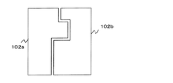
図12は、複数箇所を直角に曲げたフレキシブル基板の例を示す説明図である。図12(a)はフレキシブル基板の上面図であり、図12(b)は側面図である。図13は、図12に例示するフレキシブル基板を形成するための金型を示す。金型102aは凸部を有し、金型102bは凹部を有する。金型102a,102b間にフレキシブル基板を挟み、押圧することで図12に示す複数箇所が直角に曲がったフレキシブル基板を形成できる。   FIG. 12 is an explanatory view showing an example of a flexible substrate in which a plurality of portions are bent at right angles. FIG. 12A is a top view of the flexible substrate, and FIG. 12B is a side view. FIG. 13 shows a mold for forming the flexible substrate illustrated in FIG. The mold 102a has a convex part, and the mold 102b has a concave part. By sandwiching and pressing the flexible substrate between the molds 102a and 102b, it is possible to form a flexible substrate in which a plurality of locations shown in FIG. 12 are bent at right angles.

しかし、金型でフレキシブル基板の複数の箇所を直角に曲げようとする場合、フレキシブル基板上の曲げ位置(以下、曲げ支点と記す。)が定まらないという問題がある。図14は、金型での多段曲げ加工の問題を示す説明図である。金型102a,102b間にフレキシブル基板101を挟む。このとき、金型102aの凸部のうち金型102bに最も近づいている角部103に接している箇所が、最初の曲げ支点となる(図14(a))。この状態から、金型102aを金型102bに押し込むと、その最初の曲げ支点でフレキシブル基板は曲げられる(図14(b))。さらに金型102aを金型102bに押し込むと、金型102aの角部103とは反対側の角部104および金型102bに挟まれた部分が第2の曲げ支点となる(図14(c))。しかし、さらに金型102aを金型102bに押し込むと、第2の曲げ支点は金型102bの凹部に引き込まれていき、フレキシブル基板において角部104と接する部分がずれていってしまう(図14(d))。この結果、角部104と金型102bとによって曲げられる箇所が定まらず、フレキシブル基板によって曲げ支点にばらつきが生じるという問題がある。   However, when bending a plurality of portions of the flexible substrate with a mold at a right angle, there is a problem that a bending position on the flexible substrate (hereinafter referred to as a bending fulcrum) cannot be determined. FIG. 14 is an explanatory view showing a problem of multi-stage bending with a mold. The flexible substrate 101 is sandwiched between the molds 102a and 102b. At this time, a portion of the convex portion of the mold 102a that is in contact with the corner 103 that is closest to the mold 102b is the first bending fulcrum (FIG. 14A). From this state, when the mold 102a is pushed into the mold 102b, the flexible substrate is bent at the first bending fulcrum (FIG. 14B). When the mold 102a is further pushed into the mold 102b, the corner 104 on the opposite side to the corner 103 of the mold 102a and the portion sandwiched between the molds 102b become the second bending fulcrum (FIG. 14C). ). However, when the mold 102a is further pushed into the mold 102b, the second bending fulcrum is drawn into the recess of the mold 102b, and the portion of the flexible substrate that contacts the corner 104 is displaced (FIG. 14 ( d)). As a result, there is a problem in that a portion to be bent by the corner portion 104 and the mold 102b is not determined, and the bending fulcrum varies depending on the flexible substrate.

また、所望の形状のフレキシブル基板に対して専用の金型を製作しなければならず、金型製作のためのコストが生じていた。さらに、フレキシブル基板の形状によっては、金型の製作が困難である場合もあった。   In addition, a dedicated mold has to be manufactured for a flexible substrate having a desired shape, resulting in a cost for manufacturing the mold. Further, depending on the shape of the flexible substrate, it may be difficult to manufacture a mold.

フレキシブル基板のベースに溝やスリットを設けて曲げ加工を行う場合、曲げ部分が直角にならず、曲率のあるカーブとなり好ましくない。また、溝やスリットを設けることでフレキシブル基板の強度が低下してしまうという問題もある。   When bending is performed by providing grooves or slits in the base of the flexible substrate, the bent portion does not become a right angle, and a curved curve is not preferable. There is also a problem that the strength of the flexible substrate is reduced by providing the grooves and slits.

引用文献3に記載された発明は、直線状の材料を多段曲げ加工の対象としているので、フレキシブル基板の曲げ加工を行うことができない。   Since the invention described in the cited document 3 uses a linear material as an object of multi-stage bending, the flexible substrate cannot be bent.

そこで、フレキシブル基板上の曲げ位置がずれないようにしてフレキシブル基板に多段の曲げ加工を行うことができるフレキシブル基板の曲げ加工装置およびフレキシブル基板の曲げ加工方法を提供することを目的とする。   Therefore, an object of the present invention is to provide a flexible substrate bending apparatus and a flexible substrate bending method capable of performing multi-stage bending on the flexible substrate so that the bending position on the flexible substrate does not shift.

本発明のフレキシブル基板の曲げ加工装置は、フレキシブル基板に対して曲げ加工を行うフレキシブル基板の曲げ加工装置であって、フレキシブル基板を支持する支持テーブル(例えば、支持テーブル1)と、支持テーブルと間隔を空けて設けられる板状部材であり、支持テーブルからはみ出ているフレキシブル基板を下方から支持する下押え部(例えば、下押え板12)と、下押え部の上方に配置される上下に移動可能な板状部材であり、下降したときに下押え部との間にフレキシブル基板を挟み込む上押え部(例えば、上押え板11)と、上下に移動可能であり下降することによって、下押え部および上押え部に挟み込まれたフレキシブル基板を下方に曲げる第1曲げローラー(例えば、上曲げローラー21)と、上下に移動可能であり上昇することによって、下押え部および上押え部に挟み込まれたフレキシブル基板を上方に曲げる第2曲げローラー(例えば、下曲げローラー22)と、支持テーブルを下押え部側に移動させるテーブル移動部(例えば、テーブル移動部3)とを備え、テーブル移動部が、複数のシリンダを有し、個々のシリンダが順次、支持テーブルを移動させることによって、支持テーブルを段階的に移動させ、一つのシリンダが支持テーブルを移動させる度に、第1曲げローラーの下降または第2曲げローラーの上昇によって、フレキシブル基板の所定箇所に曲げ加工を行うことを特徴とする。 A bending apparatus for a flexible substrate according to the present invention is a bending apparatus for a flexible substrate that performs bending on a flexible substrate, and includes a support table that supports the flexible substrate (for example, the support table 1), a support table, and an interval. Is a plate-like member that is provided with a gap between the lower presser part (for example, the lower presser plate 12) that supports the flexible substrate protruding from the support table from below and can be moved up and down arranged above the lower presser part. An upper presser part (for example, the upper presser plate 11) that sandwiches the flexible substrate between the lower presser part and the lower presser part. A first bending roller (e.g., an upper bending roller 21) that bends the flexible substrate sandwiched between the upper pressing portions downward, and is movable up and down. A second bending roller (for example, the lower bending roller 22) that bends the flexible substrate sandwiched between the lower pressing portion and the upper pressing portion upward, and a table moving portion that moves the support table to the lower pressing portion side (for example, For example, the table moving unit 3) includes a plurality of cylinders, and each cylinder sequentially moves the support table to move the support table step by step. Each time the support table is moved, a bending process is performed on a predetermined portion of the flexible substrate by lowering the first bending roller or raising the second bending roller .

テーブル移動部が制御装置により制御される構成であってもよい。 The table moving unit may be controlled by a control device .

第1曲げローラーおよび第2曲げローラーは、それぞれ上押え部および下押え部を中心に支持テーブルとは反対側に配置され、第1曲げローラーの直径と第2曲げローラーの直径とが同一であることが好ましい。The first bending roller and the second bending roller are arranged on the opposite side of the support table around the upper presser portion and the lower presser portion, respectively, and the diameters of the first bending roller and the second bending roller are the same. It is preferable.

上押え部の第1曲げローラー側の面および下押え部の第2曲げローラー側の面は、同一平面上に存在することが好ましい。It is preferable that the surface of the upper pressing portion on the first bending roller side and the surface of the lower pressing portion on the second bending roller side exist on the same plane.

本発明によれば、第1曲げローラーが下降することによって、下押え部および上押え部に挟み込まれたフレキシブル基板を下方に曲げ、第2曲げローラーが上昇することによって、下押え部および上押え部に挟み込まれたフレキシブル基板を上方に曲げ、また、テーブル移動部が支持テーブルを下押え部側に移動させる。従って、フレキシブル基板上の曲げ位置がずれないようにしてフレキシブル基板に多段の曲げ加工を行うことができ、フレキシブル基板を精度よく直角に曲げることができる。   According to the present invention, when the first bending roller is lowered, the flexible substrate sandwiched between the lower presser portion and the upper presser portion is bent downward, and when the second bending roller is raised, the lower presser portion and the upper presser are moved. The flexible substrate sandwiched between the portions is bent upward, and the table moving portion moves the support table to the lower pressing portion side. Therefore, the flexible substrate can be bent in multiple stages so that the bending position on the flexible substrate does not shift, and the flexible substrate can be accurately bent at a right angle.

以下、本発明の実施の形態を図面を参照して説明する。
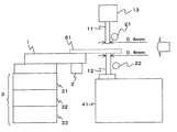
図1は、本発明の曲げ加工装置の構成を示す説明図である。本発明の曲げ加工装置は、曲げ加工の対象となるフレキシブル基板51を支持する支持テーブル1と、支持テーブルを移動させるテーブル移動部3と、支持テーブル1からはみ出ているフレキシブル基板51を下方から支持する下押え板12と、下押え板12の上方に設けられる上押え板11と、第1ローラー21と、第2ローラー22とを備える。
Hereinafter, embodiments of the present invention will be described with reference to the drawings.
FIG. 1 is an explanatory diagram showing the configuration of the bending apparatus of the present invention. The bending apparatus of the present invention supports a support table 1 that supports a flexible substrate 51 to be bent, a table moving unit 3 that moves the support table, and a flexible substrate 51 that protrudes from the support table 1 from below. A lower presser plate 12, an upper presser plate 11 provided above the lower presser plate 12, a first roller 21, and a second roller 22.

フレキシブル基板51の厚さは例えば0.14mmであるが、曲げ加工の対象となるフレキシブル基板51の厚さは0.14mmに限定されるわけではない。   The thickness of the flexible substrate 51 is, for example, 0.14 mm, but the thickness of the flexible substrate 51 to be bent is not limited to 0.14 mm.

支持テーブル1は、空気を吸い込むことによりフレキシブル基板51を吸い付けて固定する真空ポンプ2を備える。フレキシブル基板51は、例えば支持テーブル1に堀込み固定され、その上で真空ポンプ2によって吸着されて固定されてもよい。   The support table 1 includes a vacuum pump 2 that sucks and fixes the flexible substrate 51 by sucking air. For example, the flexible substrate 51 may be dug and fixed to the support table 1 and then adsorbed and fixed by the vacuum pump 2 thereon.

テーブル移動部3は複数のシリンダを備え、各シリンダがピストン(図1において図示せず。)を移動させることで、支持テーブル1を移動させる。本実施の形態では、テーブル移動部3が第1シリンダ31、第2シリンダ32、および第3シリンダ33を備えている場合を例にして説明する。テーブル移動部3が支持テーブル1を移動させると、支持テーブル1上に固定されたフレキシブル基板51も移動する。テーブル移動部3は、支持テーブル1とともにフレキシブル基板51を下押え板12方向に水平に移動させる。   The table moving unit 3 includes a plurality of cylinders, and each cylinder moves a support table 1 by moving a piston (not shown in FIG. 1). In the present embodiment, a case where the table moving unit 3 includes a first cylinder 31, a second cylinder 32, and a third cylinder 33 will be described as an example. When the table moving unit 3 moves the support table 1, the flexible substrate 51 fixed on the support table 1 also moves. The table moving unit 3 moves the flexible substrate 51 together with the support table 1 horizontally in the direction of the lower presser plate 12.

下押え板12は、支持テーブル1との間に間隔を空けて設けられる板状部材であり、板状部材の端部となる側面でフレキシブル基板51を支持する。下押え板12は、下押え板支持台41に固定されている。フレキシブル基板51を支持する下押え板12の端部の高さと支持テーブル1の高さとは等しい。   The lower presser plate 12 is a plate-like member provided with a space between the support table 1 and supports the flexible substrate 51 on the side surface serving as an end of the plate-like member. The lower presser plate 12 is fixed to the lower presser plate support base 41. The height of the end of the lower presser plate 12 that supports the flexible substrate 51 is equal to the height of the support table 1.

上押え板11は、下押え板12の上方に配置される板状部材である。上押え板11は上押え板支持部13に取り付けられ、上押え板支持部13はシリンダ(図1において図示せず。)によって上下方向に移動される。従って、上押え板11も上押え板支持部13とともに上下方向に移動する。上押え板11を移動させるシリンダをFPC押えシリンダと記す。上押え板11は、下降したときに下押え板12との間にフレキシブル基板51を挟み込む。このとき、上押え板11は、板状部材の端部となる側面でフレキシブル基板51を挟む。   The upper presser plate 11 is a plate-like member disposed above the lower presser plate 12. The upper presser plate 11 is attached to the upper presser plate support portion 13, and the upper presser plate support portion 13 is moved in the vertical direction by a cylinder (not shown in FIG. 1). Accordingly, the upper presser plate 11 also moves in the vertical direction together with the upper presser plate support portion 13. A cylinder that moves the upper presser plate 11 is referred to as an FPC presser cylinder. When the upper presser plate 11 is lowered, the flexible substrate 51 is sandwiched between the upper presser plate 12 and the lower presser plate 12. At this time, the upper presser plate 11 sandwiches the flexible substrate 51 at the side surface serving as the end portion of the plate-like member.

上押え板11および下押え板12の端部において、フレキシブル基板51を挟み込む部分の厚さは、0.4mm以上1.0mm以下であることが好ましい。図1では、この厚さが0.4mmである場合を示している。ただし、0.4mmに限定されるわけではない。また、上押え板11および下押え板12は、金属によって形成される。上押え板11および下押え板12の材料の例としてSUS304が挙げられるが、SUS304に限定されるわけではない。   In the end portions of the upper presser plate 11 and the lower presser plate 12, the thickness of the portion sandwiching the flexible substrate 51 is preferably 0.4 mm or more and 1.0 mm or less. FIG. 1 shows a case where this thickness is 0.4 mm. However, it is not necessarily limited to 0.4 mm. Further, the upper presser plate 11 and the lower presser plate 12 are made of metal. Examples of the material of the upper presser plate 11 and the lower presser plate 12 include SUS304, but are not limited to SUS304.

第1ローラー21および第2ローラー22はいずれも、上押え板11および下押え板12を中心に支持テーブル1の反対側に設けられる。そして、第1ローラー21および第2ローラー22はそれぞれ、上押え板11および下押え板12の近傍に配置され、上押え板11および下押え板12の直近で上下方向に移動し、その移動に伴ってフレキシブル基板を曲げる。第1ローラー21は、第2ローラー22の上方に設けられ、第1ローラー21の原点位置から下降して上押え板11および下押え板12に挟まれたフレキシブル基板51を下方向に直角に曲げる。第1ローラー21の原点位置は、フレキシブル基板を支持する下押え板12の端部よりも上方である。また第2ローラー22は、第2ローラー22の原点位置から上昇して上押え板11および下押え板12に挟まれたフレキシブル基板51を上方向に直角に曲げる。第2ローラー22の原点位置は、フレキシブル基板を支持する下押え板12の端部よりも下方である。以下、上方に位置する第1ローラー21を上曲げローラー21と記し、下方に位置する第2ローラー22を下曲げローラー22と記す。   Both the first roller 21 and the second roller 22 are provided on the opposite side of the support table 1 with the upper presser plate 11 and the lower presser plate 12 as the center. The first roller 21 and the second roller 22 are arranged in the vicinity of the upper presser plate 11 and the lower presser plate 12, respectively, and move up and down in the immediate vicinity of the upper presser plate 11 and the lower presser plate 12, and the movement The flexible substrate is bent accordingly. The first roller 21 is provided above the second roller 22 and descends from the origin position of the first roller 21 to bend the flexible substrate 51 sandwiched between the upper presser plate 11 and the lower presser plate 12 at a right angle downward. . The origin position of the first roller 21 is above the end of the lower presser plate 12 that supports the flexible substrate. The second roller 22 rises from the origin position of the second roller 22 and bends the flexible substrate 51 sandwiched between the upper presser plate 11 and the lower presser plate 12 at a right angle upward. The origin position of the second roller 22 is below the end of the lower presser plate 12 that supports the flexible substrate. Hereinafter, the upper first roller 21 is referred to as an upper bending roller 21, and the lower second roller 22 is referred to as a lower bending roller 22.

上曲げローラー21および下曲げローラー22の直径は例えば2.0mmであるが、2.0mmに限定されるわけではない。また、上曲げローラー21および下曲げローラー22の材料として、硬度のある金属を用いる。このような材料の例としてSKD11が挙げられるが、SKD11に限定されるわけではない。   The diameters of the upper bending roller 21 and the lower bending roller 22 are, for example, 2.0 mm, but are not limited to 2.0 mm. Further, as the material of the upper bending roller 21 and the lower bending roller 22, a metal having hardness is used. An example of such a material is SKD11, but is not limited to SKD11.

図2は、図1と同様に、本発明の曲げ加工装置の構成を示す説明図であり、図1に記した矢印方向から視認した状態を模式的に示した後面図である。図1で示した構成要素と同一の構成要素には、図1と同一の符号を付す。図2に示すように、上曲げローラー21は、軸の片側が上曲げシリンダ23によって支持される。同様に、下曲げローラー22は、軸の片側が下曲げシリンダ25によって支持される。上曲げシリンダ23は、ピストン(図2において図示せず。)を移動させることで上曲げローラー21を上下方向に移動させる。下曲げシリンダ25は、ピストン(図2において図示せず。)を移動させることで下曲げローラー22を上下方向に移動させる。   FIG. 2 is an explanatory view showing the configuration of the bending apparatus of the present invention, similarly to FIG. 1, and is a rear view schematically showing a state viewed from the arrow direction shown in FIG. The same components as those shown in FIG. 1 are denoted by the same reference numerals as those in FIG. As shown in FIG. 2, the upper bending roller 21 is supported by an upper bending cylinder 23 on one side of the shaft. Similarly, the lower bending roller 22 is supported by a lower bending cylinder 25 on one side of the shaft. The upper bending cylinder 23 moves the upper bending roller 21 in the vertical direction by moving a piston (not shown in FIG. 2). The lower bending cylinder 25 moves the lower bending roller 22 in the vertical direction by moving a piston (not shown in FIG. 2).

上曲げシリンダ23は、上曲げローラー21を原点位置から下降させる場合、フレキシブル基板51を支持している下押え板12の端部の高さより低い位置まで下降させる。また、下曲げシリンダ25は、下曲げローラー22を原点位置から上昇させる場合、下降した状態の上押え板11の端部よりも高い位置まで情報させる。   The upper bending cylinder 23 lowers the upper bending roller 21 to a position lower than the height of the end portion of the lower presser plate 12 supporting the flexible substrate 51 when lowering the upper bending roller 21 from the origin position. Moreover, when raising the lower bending roller 22 from an origin position, the lower bending cylinder 25 is made to inform to a position higher than the edge part of the upper presser plate 11 in the lowered state.

また、上曲げシリンダ23はベアリングによって上曲げローラー21を支持し、上曲げローラー21は回転可能である。同様に、下曲げシリンダ25もベアリングによって下曲げローラー22を支持し、下曲げローラー22も回転可能である。   The upper bending cylinder 23 supports the upper bending roller 21 by a bearing, and the upper bending roller 21 is rotatable. Similarly, the lower bending cylinder 25 also supports the lower bending roller 22 by a bearing, and the lower bending roller 22 is also rotatable.

上曲げシリンダ23および下曲げシリンダ25は、下押え板12を中心にして互いに反対側に位置するように配置される。   The upper bending cylinder 23 and the lower bending cylinder 25 are disposed so as to be located on opposite sides of the lower presser plate 12 as a center.

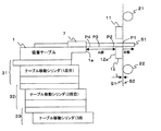
また、本発明の曲げ加工装置は、各シリンダを制御する制御装置を備える。図3は、各シリンダを制御する制御装置を示す説明図である。制御装置61は、上曲げシリンダ23および下曲げシリンダ25の動作の開始および停止を制御する。同様に、制御装置61は、上押え板11および上押え板支持部13(図1参照。)を移動させるFPC押えシリンダ55の動作の開始および停止を制御する。また、制御装置61は、第1シリンダ31、第2シリンダ32および第3シリンダ33の動作の開始および停止を制御する。さらに、制御装置61は、フレキシブル基板51を吸着する真空ポンプ2の吸着動作の停止を制御する。   Moreover, the bending apparatus of this invention is provided with the control apparatus which controls each cylinder. FIG. 3 is an explanatory diagram illustrating a control device that controls each cylinder. The control device 61 controls the start and stop of the operations of the upper bending cylinder 23 and the lower bending cylinder 25. Similarly, the control device 61 controls the start and stop of the operation of the FPC presser cylinder 55 that moves the upper presser plate 11 and the upper presser plate support portion 13 (see FIG. 1). The control device 61 controls the start and stop of the operations of the first cylinder 31, the second cylinder 32, and the third cylinder 33. Furthermore, the control device 61 controls the stop of the suction operation of the vacuum pump 2 that sucks the flexible substrate 51.

制御装置61は、第1シリンダ31、第2シリンダ32あるいは第3シリンダ33のいずれかに支持テーブル1を移動させる場合、FPC押えシリンダ55に上押え板11を上昇させる。また、下曲げシリンダ25に下曲げローラー22を原点位置に移動させ、上曲げシリンダ23に上曲げローラー21を原点位置に移動させる。従って、フレキシブル基板は、上押え板11が下押え板12から離れ、各ローラー21,22が原点位置にある状態で移動する。   When the control device 61 moves the support table 1 to any one of the first cylinder 31, the second cylinder 32, and the third cylinder 33, the control device 61 raises the upper presser plate 11 to the FPC presser cylinder 55. Further, the lower bending roller 22 is moved to the origin position in the lower bending cylinder 25, and the upper bending roller 21 is moved to the origin position in the upper bending cylinder 23. Therefore, the flexible substrate moves in a state where the upper presser plate 11 is separated from the lower presser plate 12 and the rollers 21 and 22 are at the origin positions.

また、制御装置61は、上曲げローラー21または下曲げローラー22を移動させる場合、第1シリンダ31、第2シリンダ32および第3シリンダ33を停止させ、さらにFPC押えシリンダ55に上押え板11を下降させる。従って、フレキシブル基板が静止して上押え板11および下押え板12によって挟まれた状態で曲げ加工が行われる。   Further, when the upper bending roller 21 or the lower bending roller 22 is moved, the control device 61 stops the first cylinder 31, the second cylinder 32, and the third cylinder 33, and further moves the upper presser plate 11 to the FPC presser cylinder 55. Lower. Therefore, bending is performed in a state where the flexible substrate is stationary and sandwiched between the upper presser plate 11 and the lower presser plate 12.

図4は、フレキシブル基板51における曲げ位置と支持テーブルの移動との関係を示す説明図である。ここでは、フレキシブル基板51に対して4回曲げ加工を行う場合を例にして説明する。   FIG. 4 is an explanatory diagram showing the relationship between the bending position on the flexible substrate 51 and the movement of the support table. Here, a case where the flexible substrate 51 is bent four times will be described as an example.

フレキシブル基板51は支持テーブル1上に配置される。また、支持テーブル1は、フレキシブル基板51に実装された回路(図示せず。)を保護するための金属製のカバー7を上面の下押え板12側に有している。フレキシブル基板51は、支持テーブル1上に配置され、カバー7によって保護される。なお、カバー7は、支持テーブル1全体を覆うものでなくてもよい。   The flexible substrate 51 is disposed on the support table 1. Further, the support table 1 has a metal cover 7 for protecting a circuit (not shown) mounted on the flexible substrate 51 on the lower presser plate 12 side of the upper surface. The flexible substrate 51 is disposed on the support table 1 and is protected by the cover 7. Note that the cover 7 may not cover the entire support table 1.

また、第1シリンダ31、第2シリンダ32および第3シリンダ33は、それぞれが備える各ピストンの位置を初期位置に移動させる。この初期位置は、シリンダストッパ(図示せず。)によって決定される。この初期状態における支持テーブル1と下押え板12との距離(図4に示すA部の長さ)は15mm以下であることが好ましい。すなわち、支持テーブル1の下押え板12側の面1aと、下押え板12の支持テーブル1側の面12aとの距離が15mm以下であることが好ましい。初期状態における支持テーブル1と下押え板12との距離が15mm以下であることによって、支持テーブル1および下押え板12間におけるフレキシブル基板51のたわみを防止できる。   Moreover, the 1st cylinder 31, the 2nd cylinder 32, and the 3rd cylinder 33 move the position of each piston with which each is provided to an initial position. This initial position is determined by a cylinder stopper (not shown). In this initial state, the distance between the support table 1 and the lower presser plate 12 (the length of the portion A shown in FIG. 4) is preferably 15 mm or less. That is, the distance between the surface 1a on the lower presser plate 12 side of the support table 1 and the surface 12a on the support table 1 side of the lower presser plate 12 is preferably 15 mm or less. When the distance between the support table 1 and the lower presser plate 12 in the initial state is 15 mm or less, the flexible substrate 51 can be prevented from being bent between the support table 1 and the lower presser plate 12.

フレキシブル基板51の曲げ位置をP1〜P4とする。フレキシブル基板51は、最初の曲げ位置P1が下押え板12のローラー側の面から所定距離はみ出すように配置される。この所定距離について説明する。上押え板11と下押え板12のローラー側の面は、同一平面上に存在する。この平面をS1とする。また、上曲げローラー21と下曲げローラー22の直径は同一であり、上曲げローラ21の中心軸は下曲げローラー22の中心軸の真上に位置し、その2つの中心軸は平行である。従って、円柱である上曲げローラー21と下曲げローラー22の接平面は2つ存在し、そのうち上押え板11および下押え板12に近い方の接平面をS2とする。上記の所定距離は、上押え板11と下押え板12それぞれのローラー側の面を含む平面S1と、上曲げローラー21および下曲げローラー22の接平面のうち押え板11,12に近い方の接平面S2との距離L以下であればよい。また、この所定距離が0であり、最初の曲げ位置P1が下押え板12のローラー側の面に位置するようにフレキシブル基板51が配置されていてもよい。   The bending positions of the flexible substrate 51 are P1 to P4. The flexible substrate 51 is arranged such that the initial bending position P1 protrudes from the roller-side surface of the lower presser plate 12 by a predetermined distance. This predetermined distance will be described. The surfaces of the upper presser plate 11 and the lower presser plate 12 on the roller side are on the same plane. Let this plane be S1. Moreover, the diameter of the upper bending roller 21 and the lower bending roller 22 is the same, the central axis of the upper bending roller 21 is located just above the central axis of the lower bending roller 22, and the two central axes are parallel. Accordingly, there are two tangent planes of the upper bending roller 21 and the lower bending roller 22 which are cylinders, and the tangential plane closer to the upper pressing plate 11 and the lower pressing plate 12 is defined as S2. The predetermined distance is the one closer to the presser plates 11 and 12 among the plane S1 including the roller-side surfaces of the upper presser plate 11 and the lower presser plate 12 and the tangential planes of the upper bending roller 21 and the lower bending roller 22. What is necessary is just to be the distance L or less with the tangent plane S2. Further, the flexible substrate 51 may be arranged such that the predetermined distance is 0 and the first bending position P1 is positioned on the roller side surface of the lower presser plate 12.

なお、下押え板12よりもローラー側に位置する部分(図4に示すB部)はたわんでいても曲げ加工に影響しないので、図4に示すB部はたわんでいてもよい。なお、フレキシブル基板1の表面のうち、下押え板12よりもローラー側に位置する部分(B部)や、支持テーブル1上に位置する部分には、回路が実装されていてもよい。これらの部分に回路が実装されていても、上押え板11は上下に移動可能であるので、フレキシブル基板を支持テーブル1および下押え板12上に配置することができる。ただし、初期位置における支持テーブル1と下押え板12との間(図4に示すA部)には回路は実装されない。   In addition, even if the part (B part shown in FIG. 4) located in the roller side rather than the lower presser plate 12 is bent, it does not affect a bending process, Therefore B part shown in FIG. 4 may be bent. A circuit may be mounted on a portion (B portion) located on the roller side of the lower presser plate 12 or a portion located on the support table 1 on the surface of the flexible substrate 1. Even if circuits are mounted on these portions, the upper presser plate 11 can move up and down, so that the flexible substrate can be arranged on the support table 1 and the lower presser plate 12. However, a circuit is not mounted between the support table 1 and the lower presser plate 12 at the initial position (A portion shown in FIG. 4).

第1シリンダ31、第2シリンダ32および第3シリンダ33は、順次に支持テーブル1を移動させる。ここでは第3シリンダ33、第2シリンダ32、第1シリンダ31の順番に支持テーブル1を移動させる場合を例にして説明するが、各シリンダ31〜33が支持テーブル1を移動させる順番はこの例に限定されない。   The first cylinder 31, the second cylinder 32, and the third cylinder 33 sequentially move the support table 1. Here, the case where the support table 1 is moved in the order of the third cylinder 33, the second cylinder 32, and the first cylinder 31 will be described as an example, but the order in which the cylinders 31 to 33 move the support table 1 is an example of this. It is not limited to.

ローラー21,22のいずれか一方が曲げ位置P1での曲げ加工を行った後、第3シリンダ33は、第2シリンダ32および第1シリンダ31ごと支持テーブル1を移動させる。このときの移動距離は予め制御装置61(図3参照。)に設定されている。本例では、曲げ位置P1,P2の間隔だけ移動させる。この結果、曲げ位置P2が下押え板12のローラー側の面から所定距離(図4に示すL以下の距離)はみ出した位置まで移動し、ローラー21,22のいずれかが曲げ位置P2での曲げ加工を行う。   After any one of the rollers 21 and 22 performs the bending process at the bending position P <b> 1, the third cylinder 33 moves the support table 1 together with the second cylinder 32 and the first cylinder 31. The moving distance at this time is set in advance in the control device 61 (see FIG. 3). In this example, it is moved by an interval between the bending positions P1 and P2. As a result, the bending position P2 moves to a position where a predetermined distance (distance equal to or less than L shown in FIG. 4) protrudes from the roller side surface of the lower presser plate 12, and either of the rollers 21, 22 is bent at the bending position P2. Processing.

曲げ位置P2での曲げ加工後、第2シリンダ32は、第1シリンダ31ごと支持テーブル1を移動させる。このときの移動距離も予め制御装置61に設定されている。本例では、曲げ位置P2,P3の間隔だけ移動させる。この結果、曲げ位置P3が下押え板12のローラー側の面から所定距離(図4に示すL以下の距離)はみ出した位置まで移動し、ローラー21,22のいずれかが曲げ位置P3での曲げ加工を行う。   After the bending process at the bending position P <b> 2, the second cylinder 32 moves the support table 1 together with the first cylinder 31. The moving distance at this time is also set in the control device 61 in advance. In this example, it is moved by an interval between the bending positions P2 and P3. As a result, the bending position P3 moves to a position where a predetermined distance (distance equal to or less than L shown in FIG. 4) protrudes from the roller side surface of the lower presser plate 12, and either of the rollers 21 and 22 is bent at the bending position P3. Processing.

同様に、曲げ位置P3での曲げ加工後、第1シリンダ31は支持テーブル1を移動させる。このときの移動距離も予め制御装置61に設定されている。本例では、曲げ位置P3,P4の間隔だけ移動させる。この結果、曲げ位置P4が下押え板12のローラー側の面から所定距離(図4に示すL以下の距離)はみ出した位置まで移動し、ローラー21,22のいずれかが曲げ位置P4での曲げ加工を行う。   Similarly, the 1st cylinder 31 moves the support table 1 after the bending process in the bending position P3. The moving distance at this time is also set in the control device 61 in advance. In this example, it is moved by an interval between the bending positions P3 and P4. As a result, the bending position P4 moves to a position where a predetermined distance (distance equal to or less than L shown in FIG. 4) protrudes from the roller side surface of the lower presser plate 12, and either of the rollers 21, 22 is bent at the bending position P4. Processing.

最後の曲げ位置がカバー7および支持テーブル1の端部に近い位置である場合がある。例えば、図4に示す例において、曲げ位置P4とカバー7との距離が0.5mm程度である場合もある。このような場合であっても、上押え板11および下押え板12の端部におけるフレキシブル基板を挟み込む部分の厚さが0.4mmである場合には、カバー7および支持テーブル1に近い位置(0.5mm程度)で、曲げ加工を行うことができる。   The last bending position may be a position close to the ends of the cover 7 and the support table 1. For example, in the example shown in FIG. 4, the distance between the bending position P4 and the cover 7 may be about 0.5 mm. Even in such a case, when the thickness of the portion sandwiching the flexible substrate at the ends of the upper presser plate 11 and the lower presser plate 12 is 0.4 mm, the position is close to the cover 7 and the support table 1 ( Bending can be performed at about 0.5 mm).

制御装置61は、予めテーブル移動部3の各シリンダ31〜33による移動量をそれぞれ設定される。そして、オペレータの操作によって動作開始が指示されると、テーブル移動部3のシリンダによる支持テーブル1の移動と上曲げローラー21または下曲げローラー22による曲げ加工を繰り返し、フレキシブル基板51に対する多段の曲げ加工を行う。また、各曲げ位置において上曲げローラー21を下降さるのか下曲げローラー22を上昇させるのかについても、予め制御装置61に設定されている。   In the control device 61, the amount of movement by each of the cylinders 31 to 33 of the table moving unit 3 is set in advance. Then, when an operation start is instructed by the operator's operation, the movement of the support table 1 by the cylinder of the table moving unit 3 and the bending process by the upper bending roller 21 or the lower bending roller 22 are repeated to perform multi-stage bending process on the flexible substrate 51. I do. Whether the upper bending roller 21 is lowered or the lower bending roller 22 is raised at each bending position is set in the control device 61 in advance.

また、真空ポンプ2によるフレキシブル基板51の吸着は、例えば、オペレータの操作によって開始され、制御装置61は、フレキシブル基板51に対する多段の曲げ加工を終了した後、真空ポンプ2に吸着を停止させる。   Further, the suction of the flexible substrate 51 by the vacuum pump 2 is started, for example, by an operator's operation, and the control device 61 stops the suction by the vacuum pump 2 after finishing the multistage bending process for the flexible substrate 51.

なお、移動の際、上押え板11は上昇していて、フレキシブル基板51は支持テーブル1および下押え板12によって支持されている。従って、フレキシブル基板51をスムーズに移動させることができる。   During the movement, the upper presser plate 11 is raised, and the flexible substrate 51 is supported by the support table 1 and the lower presser plate 12. Therefore, the flexible substrate 51 can be moved smoothly.

次に、図5を参照して、曲げ加工時の曲げの強さとローラー等との関係について説明する。ローラー21,22と上押え板11および下押え板12との間隔Wが狭いほど曲げの強さが増し、広いほど曲げの強さが弱まる。また、上押え板11が下降して下押え板12との間にフレキシブル基板51を挟み込んだときの上押え板11および下押え板12の間隔が狭いほど曲げの強さが増し、広いほど曲げの強さが弱まる。また、上押え板11および下押え板12の端部のコーナー111,112の曲率半径が小さいほど曲げの強さが増し、大きいほど曲げの強さが弱まる。曲げ加工によりフレキシブル基板51への影響(傷の発生や断線等)が生じる場合には、曲げの強さを弱めるように調節すればよい。   Next, with reference to FIG. 5, the relationship between the bending strength at the time of a bending process, a roller, etc. is demonstrated. The bending strength increases as the distance W between the rollers 21 and 22 and the upper pressing plate 11 and the lower pressing plate 12 decreases, and the bending strength decreases as the distance W increases. Further, the bending strength increases as the distance between the upper presser plate 11 and the lower presser plate 12 when the upper presser plate 11 is lowered and the flexible substrate 51 is sandwiched between the upper presser plate 12 and the lower presser plate 12 is increased. The strength of is weakened. Further, the bending strength increases as the radius of curvature of the corners 111 and 112 at the ends of the upper pressing plate 11 and the lower pressing plate 12 decreases, and the bending strength decreases as the radius increases. If the bending process affects the flexible substrate 51 (scratches, breakage, etc.), the bending strength may be adjusted to be weakened.

次に、本発明の曲げ加工装置が備えるシリンダの動作について説明する。   Next, the operation of the cylinder provided in the bending apparatus of the present invention will be described.

図6は、下曲げシリンダ25および上曲げシリンダ23の動作を示す説明図である。図6(a)は、下曲げローラー22および上曲げローラー21を原点位置に配置している状態を示す。図6(b)は、下曲げローラー22を上昇させた状態を示す。図6(c)は、上曲げローラーを下降させた状態を示す。なお、図6(a)〜(c)において、上段は下曲げシリンダ25および上曲げシリンダ23上面図であり、下段は正面図である。下曲げシリンダ25はピストン25aを備え、下曲げローラー22はピストン25aとともに移動する支持部25bに支持されている。同様に、上曲げシリンダ23はピストン23aを備え、上曲げローラー21はピストン23aとともに移動する支持部23bに支持されている。   FIG. 6 is an explanatory diagram showing the operation of the lower bending cylinder 25 and the upper bending cylinder 23. FIG. 6A shows a state where the lower bending roller 22 and the upper bending roller 21 are arranged at the origin position. FIG. 6B shows a state where the lower bending roller 22 is raised. FIG. 6C shows a state where the upper bending roller is lowered. 6A to 6C, the upper stage is a top view of the lower bending cylinder 25 and the upper bending cylinder 23, and the lower stage is a front view. The lower bending cylinder 25 includes a piston 25a, and the lower bending roller 22 is supported by a support portion 25b that moves together with the piston 25a. Similarly, the upper bending cylinder 23 includes a piston 23a, and the upper bending roller 21 is supported by a support portion 23b that moves together with the piston 23a.

下曲げローラー22および上曲げローラー21を原点位置に配置する場合(図6(a)参照。)、下曲げシリンダ25はピストン25aを下降させた状態とする。この結果、下曲げローラー22もピストン25aとともに下降し、下曲げローラー22の原点位置に配置される。また、上曲げシリンダ23はピストン23aを上昇させた状態とする。この結果、上曲げローラー21もピストン23aとともに上昇し、上曲げローラー21の原点位置に配置される。   When the lower bending roller 22 and the upper bending roller 21 are disposed at the origin position (see FIG. 6A), the lower bending cylinder 25 is in a state where the piston 25a is lowered. As a result, the lower bending roller 22 is also lowered together with the piston 25 a and is disposed at the origin position of the lower bending roller 22. Further, the upper bending cylinder 23 is in a state where the piston 23a is raised. As a result, the upper bending roller 21 also rises with the piston 23 a and is disposed at the origin position of the upper bending roller 21.

下曲げローラー22を上昇させる場合(図6(b)参照。)、下曲げシリンダ25はピストン25aを上昇させる。すると、下曲げローラー22もピストン25aとともに上昇し、下押え部12および上押え部11に挟み込まれたフレキシブル基板を上方向に曲げる。なお、図6では、下押え部12、上押え部11およびフレキシブル基板の図示を省略している。   When the lower bending roller 22 is raised (see FIG. 6B), the lower bending cylinder 25 raises the piston 25a. Then, the lower bending roller 22 also rises with the piston 25a, and bends the flexible substrate sandwiched between the lower presser portion 12 and the upper presser portion 11 upward. In FIG. 6, illustration of the lower presser portion 12, the upper presser portion 11, and the flexible substrate is omitted.

上曲げローラー21を下降させる場合(図6(c)参照。)、上曲げシリンダ23はピストン23aを下降させる。すると、上曲げローラー21もピストン23aとともに上昇し、下押え部12および上押え部11に挟み込まれたフレキシブル基板を上方向に曲げる。   When the upper bending roller 21 is lowered (see FIG. 6C), the upper bending cylinder 23 lowers the piston 23a. Then, the upper bending roller 21 is also lifted together with the piston 23a, and the flexible substrate sandwiched between the lower pressing portion 12 and the upper pressing portion 11 is bent upward.

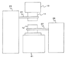
図7は、テーブル移動部3が備える第1シリンダ31、第2シリンダ32および第3シリンダ33の動作を示す説明図である。なお、図7では、第1シリンダ31、第2シリンダ32および第3シリンダ33をそれぞれ、1段移動シリンダ、2段移動シリンダ、3段移動シリンダと記している。また、図7(a)〜(d)において、左側の図は上面図であり、右側の図は側面図である。   FIG. 7 is an explanatory diagram showing operations of the first cylinder 31, the second cylinder 32, and the third cylinder 33 provided in the table moving unit 3. In FIG. 7, the first cylinder 31, the second cylinder 32, and the third cylinder 33 are referred to as a one-stage moving cylinder, a two-stage moving cylinder, and a three-stage moving cylinder, respectively. 7A to 7D, the left side is a top view, and the right side is a side view.

第1シリンダはピストン31aを備え、支持テーブル1はピストン31aとともに移動する支持部材に固定されている。第2シリンダはピストン32aを備え、第1シリンダはピストン32aとともに移動する支持部材に固定されている。第3シリンダはピストン33aを備え、第2シリンダはピストン33aとともに移動する支持部材に固定されている。   The first cylinder includes a piston 31a, and the support table 1 is fixed to a support member that moves together with the piston 31a. The second cylinder includes a piston 32a, and the first cylinder is fixed to a support member that moves together with the piston 32a. The third cylinder includes a piston 33a, and the second cylinder is fixed to a support member that moves together with the piston 33a.

図7(a)は、初期状態における各シリンダの状態を示している。第1シリンダは、第1シリンダ内のピストン31aを前進させた状態とする。同様に、第2シリンダは、第2シリンダ内のピストン32aを前進させた状態とし、第3シリンダは、第3シリンダ内のピストン33aを前進させた状態とする。なお、ここでは、「前進させる」とは、下押え板12(図7において図示せず。)と反対方向に移動させることを意味し、「後退させる」とは、下押え板12の方向に移動させることを意味する。すなわち、図7(a)に示す初期状態では、支持テーブル1は、下押え板12から遠ざけられている。   FIG. 7A shows the state of each cylinder in the initial state. The 1st cylinder makes the piston 31a in the 1st cylinder advance. Similarly, the second cylinder is in a state in which the piston 32a in the second cylinder is advanced, and the third cylinder is in a state in which the piston 33a in the third cylinder is advanced. Here, “advance” means moving in the opposite direction to the lower presser plate 12 (not shown in FIG. 7), and “retreat” means in the direction of the lower presser plate 12. It means to move. That is, in the initial state shown in FIG. 7A, the support table 1 is kept away from the lower presser plate 12.

図7(b)は、初期状態から第3シリンダが支持テーブル1を移動させた状態を示している。第3シリンダは、第3シリンダ内のピストン33aを後退させ、第2シリンダおよび第1シリンダごと支持テーブル1を下押え板12の方向に移動させる。   FIG. 7B shows a state in which the third cylinder moves the support table 1 from the initial state. The third cylinder moves the piston 33a in the third cylinder backward to move the support table 1 in the direction of the lower presser plate 12 together with the second cylinder and the first cylinder.

図7(c)は、第3シリンダが支持テーブル1を移動させた後に、第2シリンダが支持テーブル1を移動させた状態を示している。第2シリンダは、第2シリンダ内のピストン32aを後退させ、第1シリンダごと支持テーブル1を下押え板12の方向に移動させる。   FIG. 7C shows a state in which the second cylinder moves the support table 1 after the third cylinder moves the support table 1. The second cylinder moves the piston 32a in the second cylinder backward to move the support table 1 in the direction of the lower presser plate 12 together with the first cylinder.

図7(d)は、第2シリンダが支持テーブル1を移動させた後に、第1シリンダが支持テーブル1を移動させた状態を示している。第1シリンダは、第1シリンダ内のピストン32aを後退させ、支持テーブル1を下押え板12の方向に移動させる。   FIG. 7D shows a state in which the first cylinder moves the support table 1 after the second cylinder moves the support table 1. The first cylinder moves the piston 32 a in the first cylinder backward to move the support table 1 in the direction of the lower presser plate 12.

このように、テーブル移動部3は、初期状態から段階的に支持テーブル1を下押え板12の方向に移動させる。   In this way, the table moving unit 3 moves the support table 1 in the direction of the lower presser plate 12 step by step from the initial state.

図8は、FPC押えシリンダ55の動作を示す説明図である。FPC押えシリンダ55は、ピストン55aを備えている。そして、ピストン55aに上押え板支持部13が取り付けられ、さらに上押え板支持部13に上押え板11が取り付けられている。   FIG. 8 is an explanatory view showing the operation of the FPC presser cylinder 55. The FPC presser cylinder 55 includes a piston 55a. The upper presser plate support portion 13 is attached to the piston 55 a, and the upper presser plate 11 is further attached to the upper presser plate support portion 13.

図8(a)は、FPC押えシリンダ55が上押え板11を上昇させた状態を示している。FPC押えシリンダ55は、上押え板11を上昇させる場合、ピストン55aを上昇させる。すると、上押え板11もピストン55aとともに上昇する。図8(b)は、FPC押えシリンダ55が上押え板11を下降させた状態を示している。FPC押えシリンダ55は、上押え板11を下降させる場合、ピストン55aを下降させる。すると、上押え板11もピストン55aとともに下降する。   FIG. 8A shows a state where the FPC presser cylinder 55 raises the upper presser plate 11. The FPC presser cylinder 55 raises the piston 55a when the upper presser plate 11 is raised. Then, the upper presser plate 11 also rises with the piston 55a. FIG. 8B shows a state in which the FPC presser cylinder 55 has lowered the upper presser plate 11. The FPC presser cylinder 55 lowers the piston 55 a when lowering the upper presser plate 11. Then, the upper presser plate 11 also moves down together with the piston 55a.

図9は、本実施の形態の曲げ加工装置の各要素の動作タイミングの例を示す説明図である。以下、図3および図9を参照して、本実施の形態の曲げ加工装置の動作について説明する。なお、テーブル移動部3が備える各シリンダは初期状態(図7(a)参照。)となっていて、フレキシブル基板は、最初の曲げ位置が下押え板12のローラー側の面から所定距離(図4に示すL以下の距離)はみ出すようにして支持テーブル1に配置されているものとする。また、テーブル移動部3が備える各シリンダによる支持テーブル1の移動量は、予め制御装置61に設定されているものとする。   FIG. 9 is an explanatory diagram illustrating an example of operation timing of each element of the bending apparatus according to the present embodiment. Hereinafter, the operation of the bending apparatus of the present embodiment will be described with reference to FIGS. 3 and 9. Each cylinder included in the table moving unit 3 is in an initial state (see FIG. 7A), and the flexible substrate has a first bending position at a predetermined distance from the roller side surface of the lower presser plate 12 (see FIG. 7). It is assumed that the distance is equal to or less than L shown in FIG. Further, it is assumed that the movement amount of the support table 1 by each cylinder provided in the table moving unit 3 is set in the control device 61 in advance.

なお、図9に示す例では、上方向への曲げ加工を1回行った後、下方向への曲げ加工を3回行う場合を例示している。   In the example illustrated in FIG. 9, the case where the bending process is performed once and then the bending process is performed three times is illustrated.

上記の状態で、真空ポンプ2は、オペレータに操作され、フレキシブル基板51の吸着を開始する。また、制御装置61は、オペレータの操作によりフレキシブル基板51に対する多段の曲げ加工を開始する。図9に示す例では、制御装置61は、まず、FPC押えシリンダ55に上押え板11を下降させ、続いて、下曲げシリンダ25に下曲げローラー22を上昇させる。下曲げローラー22は、上昇してフレキシブル基板に接触する。すると、下曲げローラー22は、回転しながら上昇を続け、フレキシブル基板を上方向に曲げる。この動作により、フレキシブル基板51は最初の曲げ位置で上方向に直角に曲げられる。フレキシブル基板は、上押え板11および下押え板12に挟まれ、また、下曲げローラー22は回転しながらフレキシブル基板を曲げるので、曲げ位置がずれることはない。続いて、制御装置61は、下曲げシリンダ25に下曲げローラー22を原点位置まで下降させ、FPC押えシリンダ55に上押え板11を上昇させる。   In the above state, the vacuum pump 2 is operated by the operator and starts the suction of the flexible substrate 51. Further, the control device 61 starts multi-stage bending for the flexible substrate 51 by an operation of the operator. In the example shown in FIG. 9, the control device 61 first lowers the upper presser plate 11 to the FPC presser cylinder 55 and then raises the lower bend roller 22 to the lower bend cylinder 25. The lower bending roller 22 rises and contacts the flexible substrate. Then, the lower bending roller 22 continues to rise while rotating and bends the flexible substrate upward. By this operation, the flexible substrate 51 is bent at a right angle in the upward direction at the initial bending position. The flexible substrate is sandwiched between the upper presser plate 11 and the lower presser plate 12, and the lower bending roller 22 bends the flexible substrate while rotating, so that the bending position does not shift. Subsequently, the control device 61 lowers the lower bending roller 22 to the lower bending cylinder 25 to the origin position, and raises the upper pressing plate 11 to the FPC pressing cylinder 55.

次に、制御装置61は、第3シリンダ33にピストン33a(図7参照。)を後退させる。この移動量は予め定められている。この結果、支持テーブル1は下押え板12方向に移動して停止し、テーブル移動部3は図7(b)に示す状態となる。   Next, the control device 61 causes the third cylinder 33 to move the piston 33a (see FIG. 7) backward. This amount of movement is predetermined. As a result, the support table 1 moves in the direction of the lower presser plate 12 and stops, and the table moving unit 3 is in the state shown in FIG.

この状態で、制御装置61は、まず、FPC押えシリンダ55に上押え板11を下降させ、続いて、上曲げシリンダ23に上曲げローラー21を下降させる。上曲げローラー21は、下降してフレキシブル基板に接触する。すると、上曲げローラー21は、回転しながら下降を続け、フレキシブル基板を下方向に曲げる。この動作により、フレキシブル基板51は2番目の曲げ位置で下方向に直角に曲げられる。フレキシブル基板は、上押え板11および下押え板12に挟まれ、また、上曲げローラー21は回転しながらフレキシブル基板を曲げるので、曲げ位置がずれることはない。続いて、制御装置61は、上曲げシリンダ23に上曲げローラー21を原点位置まで上昇させ、FPC押えシリンダ55に上押え板11を上昇させる。   In this state, the control device 61 first lowers the upper presser plate 11 to the FPC presser cylinder 55 and then lowers the upper bending roller 21 to the upper bending cylinder 23. The upper bending roller 21 descends and comes into contact with the flexible substrate. Then, the upper bending roller 21 continues to descend while rotating and bends the flexible substrate downward. By this operation, the flexible substrate 51 is bent at a right angle downward at the second bending position. The flexible substrate is sandwiched between the upper pressing plate 11 and the lower pressing plate 12, and the upper bending roller 21 bends the flexible substrate while rotating, so that the bending position does not shift. Subsequently, the control device 61 raises the upper bending roller 21 to the upper bending cylinder 23 to the origin position, and raises the upper pressing plate 11 to the FPC pressing cylinder 55.

次に、制御装置61は、第2シリンダ32にピストン32a(図7参照。)を後退させる。この移動量は予め定められている。この結果、支持テーブル1は下押え板12方向に移動して停止し、テーブル移動部3は図7(c)に示す状態となる。曲げ加工装置は、この状態で3回目の曲げ加工を行う。この動作は2回目の曲げ加工と同様である。   Next, the control device 61 causes the piston 32a (see FIG. 7) to move backward in the second cylinder 32. This amount of movement is predetermined. As a result, the support table 1 moves in the direction of the lower presser plate 12 and stops, and the table moving unit 3 is in the state shown in FIG. The bending apparatus performs the third bending process in this state. This operation is similar to the second bending process.

次に、制御装置61は、第1シリンダ31にピストン31a(図7参照。)を後退させる。この移動量は予め定められている。この結果、支持テーブル1は下押え板12方向に移動して停止し、テーブル移動部3は図7(d)に示す状態となる。曲げ加工装置は、この状態で4回目の曲げ加工を行う。この動作は2回目および3回目の曲げ加工と同様である。   Next, the controller 61 causes the first cylinder 31 to move the piston 31a (see FIG. 7) backward. This amount of movement is predetermined. As a result, the support table 1 moves in the direction of the lower presser plate 12 and stops, and the table moving unit 3 enters the state shown in FIG. The bending apparatus performs the fourth bending process in this state. This operation is the same as the second and third bending processes.

続いて、制御装置61は、真空ポンプに吸着動作を停止させ、動作を終了する。   Subsequently, the control device 61 causes the vacuum pump to stop the adsorption operation and ends the operation.

ここでは図9に示すタイミングチャートに沿って動作を説明した。以下、図3、図10および図11を参照して、支持テーブル1、上押え板11、上曲げローラー21および下曲げローラー22の動作の例を説明する。図10および図11では、上曲げローラー21による曲げ加工を1回行った後、下曲げローラー22による曲げ加工を2回行い、その後上曲げローラー21による曲げ加工を1回行う場合を例にして説明する。   Here, the operation has been described along the timing chart shown in FIG. Hereinafter, examples of operations of the support table 1, the upper presser plate 11, the upper bending roller 21, and the lower bending roller 22 will be described with reference to FIGS. 3, 10, and 11. 10 and 11, an example in which the bending process by the upper bending roller 21 is performed once, the bending process by the lower bending roller 22 is performed twice, and then the bending process by the upper bending roller 21 is performed once. explain.

図10(a)は、曲げ加工装置の初期状態を示している。フレキシブル基板51は、支持テーブル1に吸着固定されている。   FIG. 10A shows an initial state of the bending apparatus. The flexible substrate 51 is fixed to the support table 1 by suction.

制御装置61が動作を開始すると、まず、制御装置61は、FPC押えシリンダ55に上押え板11を下降させ、続いて、上曲げシリンダ23に上曲げローラー21を下降させる(図10(b)参照。)。この結果、フレキシブル基板51は最初の曲げ位置で、下方向に直角に曲げられる。   When the control device 61 starts operation, first, the control device 61 lowers the upper presser plate 11 to the FPC presser cylinder 55, and then lowers the upper bending roller 21 to the upper bending cylinder 23 (FIG. 10B). reference.). As a result, the flexible substrate 51 is bent at a right angle in the downward direction at the initial bending position.

続いて、制御装置61は、上曲げシリンダ23に上曲げローラー21を原点位置まで上昇させ、FPC押えシリンダ55に上押え板11を上昇させる。そして、制御装置61は、テーブル移動部3を下押え板12方向に移動させる(図10(c)参照。)   Subsequently, the control device 61 raises the upper bending roller 21 to the upper bending cylinder 23 to the origin position, and raises the upper pressing plate 11 to the FPC pressing cylinder 55. Then, the control device 61 moves the table moving unit 3 toward the lower presser plate 12 (see FIG. 10C).

制御装置61は、この状態で、FPC押えシリンダ55に上押え板11を下降させ、続いて、下曲げシリンダ25に下曲げローラー22を上昇させる(図10(d)参照。)。この結果、フレキシブル基板51は2番目の曲げ位置で、上方向に直角に曲げられる。   In this state, the control device 61 lowers the upper presser plate 11 to the FPC presser cylinder 55 and then raises the lower bend roller 22 to the lower bend cylinder 25 (see FIG. 10D). As a result, the flexible substrate 51 is bent at a right angle in the upward direction at the second bending position.

続いて、制御装置61は、下曲げシリンダ25に下曲げローラー22を原点位置まで下降させ、FPC押えシリンダ55に上押え板11を上昇させる。そして、制御装置61は、テーブル移動部3を下押え板12方向に移動させる(図11(a)参照。)   Subsequently, the control device 61 lowers the lower bending roller 22 to the lower bending cylinder 25 to the origin position, and raises the upper pressing plate 11 to the FPC pressing cylinder 55. And the control apparatus 61 moves the table moving part 3 to the lower pressing plate 12 direction (refer Fig.11 (a)).

制御装置61は、この状態で、FPC押えシリンダ55に上押え板11を下降させ、続いて、下曲げシリンダ25に下曲げローラー22を上昇させる(図11(b)参照。)。この結果、フレキシブル基板51は3番目の曲げ位置で、上方向に直角に曲げられる。   In this state, the control device 61 lowers the upper presser plate 11 to the FPC presser cylinder 55 and then raises the lower bending roller 22 to the lower bending cylinder 25 (see FIG. 11B). As a result, the flexible substrate 51 is bent at a right angle in the upward direction at the third bending position.

続いて、制御装置61は、下曲げシリンダ25に下曲げローラー22を原点位置まで下降させ、FPC押えシリンダ55に上押え板11を上昇させる。そして、制御装置61は、テーブル移動部3を下押え板12方向に移動させる(図11(c)参照。)   Subsequently, the control device 61 lowers the lower bending roller 22 to the lower bending cylinder 25 to the origin position, and raises the upper pressing plate 11 to the FPC pressing cylinder 55. Then, the control device 61 moves the table moving unit 3 toward the lower presser plate 12 (see FIG. 11C).

制御装置61は、この状態で、FPC押えシリンダ55に上押え板11を下降させ、続いて、上曲げシリンダ23に上曲げローラー21を下降させる(図11(d)参照。)。この結果、フレキシブル基板51は4番目の曲げ位置で、下方向に直角に曲げられる。   In this state, the control device 61 lowers the upper presser plate 11 to the FPC presser cylinder 55 and then lowers the upper bending roller 21 to the upper bending cylinder 23 (see FIG. 11D). As a result, the flexible substrate 51 is bent at a right angle in the downward direction at the fourth bending position.

図11(d)に示す状態から、制御装置61は、上曲げシリンダ23に上曲げローラー21を原点位置まで上昇させ、FPC押えシリンダ55に上押え板11を上昇させる。その後、制御装置61は、真空ポンプに吸着動作を停止させ、動作を終了する。   From the state shown in FIG. 11D, the control device 61 raises the upper bending roller 21 to the upper bending cylinder 23 to the origin position, and raises the upper pressing plate 11 to the FPC pressing cylinder 55. Thereafter, the control device 61 causes the vacuum pump to stop the adsorption operation and ends the operation.

本発明によれば、支持テーブル1に固定され、テーブル移動部3によって移動されたフレキシブル基板は、上押え板11と下押え板12によって挟まれる。その状態で、上曲げローラー21がフレキシブル基板に接触し、回転しながらフレキシブル基板を曲げる。あるいは、下曲げローラー22がフレキシブル基板に接触し、回転しながらフレキシブル基板を曲げる。従って、曲げ加工時に曲げ位置がずれてしまうことを防止できる。   According to the present invention, the flexible substrate fixed to the support table 1 and moved by the table moving unit 3 is sandwiched between the upper presser plate 11 and the lower presser plate 12. In this state, the upper bending roller 21 contacts the flexible substrate and bends the flexible substrate while rotating. Alternatively, the lower bending roller 22 contacts the flexible substrate and bends the flexible substrate while rotating. Therefore, it is possible to prevent the bending position from being shifted during bending.

また、上曲げローラー21および下曲げローラー22は、上押え板11と下押え板12の近傍で上下に移動するので、曲げ位置でのカーブを抑え、精度よくフレキシブル基板を直角に曲げることができる。また、フレキシブル基板のベースに溝やスリットを設ける必要がなく、フレキシブル基板の強度の低下を防止することができる。   Moreover, since the upper bending roller 21 and the lower bending roller 22 move up and down in the vicinity of the upper pressing plate 11 and the lower pressing plate 12, it is possible to suppress the curve at the bending position and bend the flexible substrate at a right angle with high accuracy. . Moreover, it is not necessary to provide a groove or a slit in the base of the flexible substrate, and a decrease in the strength of the flexible substrate can be prevented.

また、制御装置61に、テーブル移動部3の各シリンダの移動量を設定し、各曲げ位置で上曲げローラー21を下降さるのか下曲げローラー22を上昇させるのかを設定すれば、フレキシブル基板を様々な形状に曲げることができる。そのため、所望のフレキシブル基板の形状に応じた金型をそれぞれ用意する必要がない。   Moreover, if the control device 61 sets the movement amount of each cylinder of the table moving unit 3 and sets whether the upper bending roller 21 is lowered or the lower bending roller 22 is raised at each bending position, various flexible substrates can be used. Can be bent into any shape. Therefore, it is not necessary to prepare dies corresponding to the shape of the desired flexible substrate.

本発明は、フレキシブル基板に曲げ加工を施す曲げ加工装置およびフレキシブル基板の曲げ加工方法に好適に適用される。   The present invention is suitably applied to a bending apparatus and a flexible substrate bending method for bending a flexible substrate.

本発明のフレキシブル基板の曲げ加工装置の構成を示す説明図。Explanatory drawing which shows the structure of the bending process apparatus of the flexible substrate of this invention. 本発明のフレキシブル基板の曲げ加工装置の構成を示す説明図。Explanatory drawing which shows the structure of the bending process apparatus of the flexible substrate of this invention. 各シリンダを制御する制御装置を示す説明図。Explanatory drawing which shows the control apparatus which controls each cylinder. 曲げ位置と支持テーブルの移動との関係を示す説明図。Explanatory drawing which shows the relationship between a bending position and the movement of a support table. 下押え板付近の構成要素を示す説明図。Explanatory drawing which shows the component of a lower press plate vicinity. 下曲げシリンダおよび上曲げシリンダの動作を示す説明図。Explanatory drawing which shows operation | movement of a lower bending cylinder and an upper bending cylinder. テーブル移動部が備える第1シリンダ、第2シリンダおよび第3シリンダの動作を示す説明図。Explanatory drawing which shows operation | movement of the 1st cylinder with which a table moving part is provided, a 2nd cylinder, and a 3rd cylinder. FPC押えシリンダの動作を示す説明図。Explanatory drawing which shows operation | movement of a FPC presser cylinder. 曲げ加工装置の各要素の動作タイミングの例を示す説明図。Explanatory drawing which shows the example of the operation | movement timing of each element of a bending apparatus. 支持テーブル、上押え板、上曲げローラーおよび下曲げローラーの動作の例を示す説明図。Explanatory drawing which shows the example of operation | movement of a support table, an upper pressing board, an upper bending roller, and a lower bending roller. 支持テーブル、上押え板、上曲げローラーおよび下曲げローラーの動作の例を示す説明図。Explanatory drawing which shows the example of operation | movement of a support table, an upper pressing board, an upper bending roller, and a lower bending roller. 複数箇所を直角に曲げたフレキシブル基板の例を示す説明図。Explanatory drawing which shows the example of the flexible substrate which bent the some place at right angle. 図12に例示するフレキシブル基板を形成するための金型を示す説明図。Explanatory drawing which shows the metal mold | die for forming the flexible substrate illustrated in FIG. 金型での多段曲げ加工の問題を示す説明図。Explanatory drawing which shows the problem of the multistage bending process in a metal mold | die.

符号の説明Explanation of symbols

1 支持テーブル
2 真空ポンプ
3 テーブル移動部
11 上押え板
12 下押え板
13 上押え板支持部
21 上曲げローラー(第1ローラー)
22 下曲げローラー(第2ローラー)
23 上曲げシリンダ
25 下曲げシリンダ
31 第1シリンダ
32 第2シリンダ
33 第3シリンダ
55 FPC押えシリンダ
DESCRIPTION OF SYMBOLS 1 Support table 2 Vacuum pump 3 Table moving part 11 Upper presser plate 12 Lower presser plate 13 Upper presser plate support part 21 Upper bending roller (1st roller)
22 Lower bending roller (second roller)
23 Upper bending cylinder 25 Lower bending cylinder 31 1st cylinder 32 2nd cylinder 33 3rd cylinder 55 FPC presser cylinder

Claims (4)

フレキシブル基板に対して曲げ加工を行うフレキシブル基板の曲げ加工装置であって、
フレキシブル基板を支持する支持テーブルと、
支持テーブルと間隔を空けて設けられる板状部材であり、支持テーブルからはみ出ているフレキシブル基板を下方から支持する下押え部と、
下押え部の上方に配置される上下に移動可能な板状部材であり、下降したときに下押え部との間にフレキシブル基板を挟み込む上押え部と、
上下に移動可能であり下降することによって、下押え部および上押え部に挟み込まれたフレキシブル基板を下方に曲げる第1曲げローラーと、
上下に移動可能であり上昇することによって、下押え部および上押え部に挟み込まれたフレキシブル基板を上方に曲げる第2曲げローラーと、
支持テーブルを下押え部側に移動させるテーブル移動部とを備え
前記テーブル移動部は、複数のシリンダを有し、個々のシリンダが順次、前記支持テーブルを移動させることによって、前記支持テーブルを段階的に移動させ、
一つのシリンダが前記支持テーブルを移動させる度に、前記第1曲げローラーの下降または前記第2曲げローラーの上昇によって、前記フレキシブル基板の所定箇所に曲げ加工を行う
ことを特徴とするフレキシブル基板の曲げ加工装置。
A flexible substrate bending apparatus for bending a flexible substrate,
A support table for supporting a flexible substrate;
A plate-like member provided at a distance from the support table, and a lower presser part that supports the flexible substrate protruding from the support table from below,
A plate-like member that can be moved up and down and arranged above the lower presser part, and when the lower presser part is sandwiched between the upper presser part and the lower presser part,
A first bending roller that can move up and down and bends the flexible substrate sandwiched between the lower presser part and the upper presser part by lowering; and
A second bending roller that bends the flexible substrate sandwiched between the lower presser part and the upper presser part by being movable up and down and rising;
A table moving unit that moves the support table to the lower presser side ,
The table moving unit has a plurality of cylinders, and each cylinder sequentially moves the support table to move the support table in stages.
Bending of a flexible substrate, wherein a bending process is performed on a predetermined portion of the flexible substrate by lowering the first bending roller or raising the second bending roller each time one cylinder moves the support table. Processing equipment.
前記テーブル移動部は制御装置により制御されている請求項1に記載のフレキシブル基板の曲げ加工装置。 The flexible substrate bending apparatus according to claim 1, wherein the table moving unit is controlled by a control device. 前記第1曲げローラーおよび前記第2曲げローラーは、それぞれ前記上押え部および前記下押え部を中心に前記支持テーブルとは反対側に配置され、前記第1曲げローラーの直径と前記第2曲げローラーの直径とは同一である請求項1または請求項2に記載のフレキシブル基板の曲げ加工装置。 The first bending roller and the second bending roller are disposed on the opposite side of the support table around the upper pressing portion and the lower pressing portion, respectively, and the diameter of the first bending roller and the second bending roller The apparatus for bending a flexible substrate according to claim 1 or 2, wherein the diameter of the flexible substrate is the same . 前記上押え部の第1曲げローラー側の面および前記下押え部の前記第2曲げローラー側の面は、同一平面上に存在する請求項3に記載のフレキシブル基板の曲げ加工装置。4. The flexible substrate bending apparatus according to claim 3, wherein a surface on the first bending roller side of the upper pressing portion and a surface on the second bending roller side of the lower pressing portion exist on the same plane. 5.
JP2007088963A 2007-03-29 2007-03-29 Flexible substrate bending machine Expired - Fee Related JP5020681B2 (en)

Priority Applications (1)

Application Number Priority Date Filing Date Title
JP2007088963A JP5020681B2 (en) 2007-03-29 2007-03-29 Flexible substrate bending machine

Applications Claiming Priority (1)

Application Number Priority Date Filing Date Title
JP2007088963A JP5020681B2 (en) 2007-03-29 2007-03-29 Flexible substrate bending machine

Publications (3)

Publication Number Publication Date
JP2008251695A JP2008251695A (en) 2008-10-16
JP2008251695A5 JP2008251695A5 (en) 2010-05-06
JP5020681B2 true JP5020681B2 (en) 2012-09-05

Family

ID=39976326

Family Applications (1)

Application Number Title Priority Date Filing Date
JP2007088963A Expired - Fee Related JP5020681B2 (en) 2007-03-29 2007-03-29 Flexible substrate bending machine

Country Status (1)

Country Link
JP (1) JP5020681B2 (en)

Families Citing this family (4)

* Cited by examiner, † Cited by third party
Publication number Priority date Publication date Assignee Title
JP5440007B2 (en) * 2009-07-30 2014-03-12 アイコム株式会社 Flat cable bending device
JP6306410B2 (en) * 2014-04-17 2018-04-04 日本メクトロン株式会社 Flexible printed board manufacturing method, board manufacturing jig, and board manufacturing apparatus
KR102417557B1 (en) 2017-09-05 2022-07-06 삼성디스플레이 주식회사 Display device and manufacturing method of display device and manufacturing apparatus of display device
CN110039753B (en) * 2019-03-29 2021-04-27 武汉华星光电技术有限公司 Flexible circuit board bending device and bending method thereof

Family Cites Families (3)

* Cited by examiner, † Cited by third party
Publication number Priority date Publication date Assignee Title
JPH07109066A (en) * 1993-10-13 1995-04-25 Sony Corp Substrate bending device
JPH0839156A (en) * 1994-07-29 1996-02-13 Amada Co Ltd Bender
JP2002210517A (en) * 2001-01-12 2002-07-30 Canon Inc Apparatus for bending parts

Also Published As

Publication number Publication date
JP2008251695A (en) 2008-10-16

Similar Documents

Publication Publication Date Title
KR102117337B1 (en) Apparatus for forming a glass
CN104028944B (en) Apparatus for shaping and detent mechanism thereof
CN103958088B (en) Processing unit (plant) and processing method
JP5020681B2 (en) Flexible substrate bending machine
JP6246968B1 (en) Punching device
CN103456662B (en) Substrate separator and use the base plate separation method of this device
JP4854256B2 (en) Panel processing apparatus and processing method
KR102432352B1 (en) Apparatus for forming window glass and method for manufacturing electronic device having the window
JP2007310019A (en) Positioning table device
JP2011047984A (en) Fpd module mounting device and method mounting the same
JP2008012572A (en) Roller hemming device
CN111688171B (en) Shaping tool and shaping board of bending bend
JP2018069536A (en) Scribe device and scribe method
KR101581726B1 (en) Plate processing apparatus and plate processing method
CN212903299U (en) Detection apparatus for formula of book etching equipment
JP2010058138A (en) Bending apparatus
JP2008068264A (en) Step bending method and device for carrying out the same
JP4914702B2 (en) Work positioning device
CN110780475A (en) FPC shaping mechanism that bends
KR20110111027A (en) A mold device for manufacturing hole
JP2007175760A (en) Press formed article made of metallic sheet and method for manufacturing it
JPH11204579A (en) Apparatus and method of mounting electronic component
JP3121691B2 (en) Press mold
CN219372685U (en) Flexible circuit board bending mechanism
JP2002205298A (en) Method and device for cutting plate cut material

Legal Events

Date Code Title Description
A521 Written amendment

Free format text: JAPANESE INTERMEDIATE CODE: A523

Effective date: 20100319

A621 Written request for application examination

Free format text: JAPANESE INTERMEDIATE CODE: A621

Effective date: 20100319

A521 Written amendment

Free format text: JAPANESE INTERMEDIATE CODE: A523

Effective date: 20110304

A977 Report on retrieval

Free format text: JAPANESE INTERMEDIATE CODE: A971007

Effective date: 20111005

A131 Notification of reasons for refusal

Free format text: JAPANESE INTERMEDIATE CODE: A131

Effective date: 20111011

A521 Written amendment

Free format text: JAPANESE INTERMEDIATE CODE: A523

Effective date: 20111202

TRDD Decision of grant or rejection written
A01 Written decision to grant a patent or to grant a registration (utility model)

Free format text: JAPANESE INTERMEDIATE CODE: A01

Effective date: 20120605

A01 Written decision to grant a patent or to grant a registration (utility model)

Free format text: JAPANESE INTERMEDIATE CODE: A01

A61 First payment of annual fees (during grant procedure)

Free format text: JAPANESE INTERMEDIATE CODE: A61

Effective date: 20120613

R150 Certificate of patent or registration of utility model

Ref document number: 5020681

Country of ref document: JP

Free format text: JAPANESE INTERMEDIATE CODE: R150

Free format text: JAPANESE INTERMEDIATE CODE: R150

FPAY Renewal fee payment (event date is renewal date of database)

Free format text: PAYMENT UNTIL: 20150622

Year of fee payment: 3

R250 Receipt of annual fees

Free format text: JAPANESE INTERMEDIATE CODE: R250

R250 Receipt of annual fees

Free format text: JAPANESE INTERMEDIATE CODE: R250

S111 Request for change of ownership or part of ownership

Free format text: JAPANESE INTERMEDIATE CODE: R313111

R350 Written notification of registration of transfer

Free format text: JAPANESE INTERMEDIATE CODE: R350

LAPS Cancellation because of no payment of annual fees