JP5019862B2 - Pilot type control valve - Google Patents
Pilot type control valve Download PDFInfo
- Publication number
- JP5019862B2 JP5019862B2 JP2006333412A JP2006333412A JP5019862B2 JP 5019862 B2 JP5019862 B2 JP 5019862B2 JP 2006333412 A JP2006333412 A JP 2006333412A JP 2006333412 A JP2006333412 A JP 2006333412A JP 5019862 B2 JP5019862 B2 JP 5019862B2
- Authority
- JP
- Japan
- Prior art keywords
- valve
- pilot
- valve body
- main valve
- main
- Prior art date
- Legal status (The legal status is an assumption and is not a legal conclusion. Google has not performed a legal analysis and makes no representation as to the accuracy of the status listed.)
- Active
Links
Images


Description
本発明は、空調機等の冷凍サイクルに使用するのに好適な制御弁に係り、特に、弁開度(開口面積)を任意にかつきめ細かく調整することができるパイロット型制御弁に関する。 The present invention relates to a control valve suitable for use in a refrigeration cycle such as an air conditioner, and more particularly to a pilot-type control valve capable of arbitrarily and finely adjusting a valve opening (opening area).
例えば、一台の室外機に対して複数台の室内機を有するマルチエアコンにおいて、室外機と室内機との間に配在するのに好適な制御弁としては、下記特許文献1等にも見られるように、パイロット弁として電磁弁を用いたパイロット型制御弁が知られている。
For example, in a multi-air conditioner having a plurality of indoor units for one outdoor unit, a control valve suitable for being distributed between the outdoor unit and the indoor unit is also found in
かかるパイロット型制御弁は、通常、主弁と電磁式パイロット弁とを備え、前記主弁は、冷媒が導入導出される弁室が形成される弁本体とこの弁本体内に摺動自在に嵌挿されて前記弁本体に設けられた主弁座に接離する主弁体とを有し、前記主弁体は、圧縮コイルばねにより常時上方(開弁方向)に付勢されている。また、前記電磁式パイロット弁(の画成部材)は、前記弁本体の上面開口を塞ぐようにその上部に密閉固定される。 Such a pilot-type control valve usually includes a main valve and an electromagnetic pilot valve, and the main valve is slidably fitted into a valve body in which a valve chamber into which refrigerant is introduced and led is formed and the valve body. And a main valve body that is inserted into and separated from a main valve seat provided in the valve body, and the main valve body is constantly urged upward (in the valve opening direction) by a compression coil spring. Further, the electromagnetic pilot valve (the defining member) is hermetically fixed to the upper portion so as to close the upper surface opening of the valve body.
前記弁本体内において主弁体と主弁座との間に前記弁室が形成され、主弁体と前記電磁式パイロット弁(の画成部材)との間に背圧室が画成される。 In the valve body, the valve chamber is formed between the main valve body and the main valve seat, and a back pressure chamber is defined between the main valve body and the electromagnetic pilot valve (the defining member). .
前記主弁体には、上下に貫通するようにパイロット通路が形成され、このパイロット通路の上端部に設けられたパイロット弁座(弁口)に前記電磁式パイロット弁の弁体が接離するようにされている。加えて、前記弁室と背圧室とを連通するように、前記主弁体あるいは弁本体等に均圧通路が形成されている。 A pilot passage is formed in the main valve body so as to penetrate vertically, so that the valve body of the electromagnetic pilot valve contacts and separates from a pilot valve seat (valve port) provided at an upper end portion of the pilot passage. Has been. In addition, a pressure equalizing passage is formed in the main valve body or the valve body so as to communicate the valve chamber and the back pressure chamber.
このような構成とされたパイロット型制御弁では、電磁式パイロット弁に通電されていないときには、パイロット弁内の閉弁ばねの付勢力により、パイロット弁の弁体がパイロット弁座を閉じるとともに、パイロット弁の弁体が主弁体を下方(閉弁方向)に押圧するので、主弁も閉状態にされる。したがって、このときは、弁室に導入された高圧の冷媒が出口へは導出されないが、この高圧冷媒が前記均圧通路を通じて背圧室に導入されるので、背圧室も高圧となり、主弁体が主弁座に強く押し付けられる。 In the pilot type control valve having such a configuration, when the electromagnetic pilot valve is not energized, the pilot valve body closes the pilot valve seat and the pilot valve seat is closed by the biasing force of the valve closing spring in the pilot valve. Since the valve body of the valve presses the main valve body downward (in the valve closing direction), the main valve is also closed. Therefore, at this time, the high-pressure refrigerant introduced into the valve chamber is not led out to the outlet, but since the high-pressure refrigerant is introduced into the back pressure chamber through the pressure equalizing passage, the back pressure chamber also becomes high pressure, and the main valve The body is strongly pressed against the main valve seat.
一方、前記閉状態から電磁式パイロット弁に通電されると、パイロット弁体が引き上げられてパイロット弁座から離れ、パイロット弁が開く。これにより、背圧室の冷媒がパイロット通路を通じて出口へ導出され、背圧室の圧力が低下して、圧縮コイルばねの付勢力等の主弁体を押し上げる力(開弁させる力)が主弁体を押し下げる力(閉弁させる力)に打ち勝ち、主弁体が押し上げられて、主弁が開く。 On the other hand, when the electromagnetic pilot valve is energized from the closed state, the pilot valve body is lifted away from the pilot valve seat and the pilot valve is opened. As a result, the refrigerant in the back pressure chamber is led out to the outlet through the pilot passage, the pressure in the back pressure chamber decreases, and the force that pushes up the main valve body such as the urging force of the compression coil spring (force to open the valve) The force to push down the body (force to close the valve) is overcome, the main valve body is pushed up, and the main valve opens.
前記した如くの従来のパイロット型制御弁では、小口径のパイロット弁を開けば、それに応動して大口径の主弁を開くことができるので、大口径の主弁の開閉を小さな駆動力で行える等の利点を有しているが、パイロット弁として電磁弁を用いているので、次のような短所があった。すなわち、実質的に全閉状態と全開状態の二位置しかとることができず、弁開度(開口面積)をきめ細かく調整することはできない。また、主弁が開弁するまでパイロット弁の開口面積分しか開いていないので、弁全体の開口面積が小さく、均圧に時間がかかり、応答性が良いとは言えない。さらに、主弁が開弁するとき、開口面積が一気に増大するので、流量が急激に変化して耳障りな騒音が発生する。 In the conventional pilot type control valve as described above, if the small-diameter pilot valve is opened, the large-diameter main valve can be opened in response to it, so that the large-diameter main valve can be opened and closed with a small driving force. However, since the solenoid valve is used as the pilot valve, there are the following disadvantages. That is, only two positions of the fully closed state and the fully open state can be taken substantially, and the valve opening degree (opening area) cannot be finely adjusted. Further, since only the opening area of the pilot valve is opened until the main valve is opened, the opening area of the entire valve is small, it takes time to equalize pressure, and it cannot be said that the responsiveness is good. Further, when the main valve opens, the opening area increases at a stretch, so that the flow rate changes rapidly and annoying noise is generated.
本発明は、上記事情に鑑みてなされたもので、その目的とするところは、弁開度を任意にかつきめ細かく調整することができるとともに、騒音の発生を効果的に抑えることができ、さらに、優れた応答性、動作安定性、制御特性等が得られるパイロット型制御弁を提供することにある。 The present invention has been made in view of the above circumstances, and the object of the present invention is that the valve opening can be arbitrarily and finely adjusted, and the generation of noise can be effectively suppressed. An object of the present invention is to provide a pilot type control valve that can obtain excellent responsiveness, operational stability, control characteristics, and the like.
前記の目的を達成すべく、本発明に係るパイロット型制御弁は、基本的には、主弁と電動式パイロット弁とを備えたパイロット型制御弁であって、前記主弁は、流体が導入導出される弁室が形成された弁本体と、該弁本体内に摺動自在に嵌挿されて前記弁本体に設けられた主弁口を開閉する大径部と小径部とを有する断面逆凸字状のピストン型の主弁体と、を有し、前記電動式パイロット弁は、前記弁本体の上面開口を塞ぐように取り付けられて前記主弁体との間に背圧室を画成する画成部材と、前記主弁体に設けられたパイロット弁口を開閉するパイロット弁体と、を有し、前記主弁には、前記弁室と前記背圧室とを連通する均圧通路が設けられるとともに、前記主弁体が圧縮コイルばねにより常時開弁方向に付勢されており、かつ、前記パイロット弁体の開弁方向の移動に追従するように、前記主弁体が開弁方向に移動するようにされている。 In order to achieve the above object, a pilot type control valve according to the present invention is basically a pilot type control valve having a main valve and an electric pilot valve, and a fluid is introduced into the main valve. An inverted cross section having a valve body formed with a valve chamber to be led out, and a large-diameter portion and a small-diameter portion that are slidably inserted into the valve body and open and close a main valve port provided in the valve body. A piston-type main valve body having a convex shape, and the electric pilot valve is attached so as to close an upper surface opening of the valve body, and defines a back pressure chamber between the main valve body and the main valve body. And a pressure equalizing passage that communicates the valve chamber and the back pressure chamber to the main valve, the pilot valve body opening and closing a pilot valve port provided in the main valve body. And the main valve body is normally urged in the valve opening direction by a compression coil spring, and the So as to follow the movement of the valve opening direction of the pilots valve body, the main valve body is adapted to move in the valve opening direction.
そして、前記弁本体は、前記主弁体が摺動自在に嵌挿される弁室筒体と、該弁室筒体の下部に設けられた段付き円筒状部を持つ弁座部材と、を有し、前記圧縮コイルばねは、前記主弁体の大径部に設けられた下向き突出部付き下端面部と前記弁座部材の段丘面部との間に介装されるとともに、その上下端部が前記主弁体の下向き突出部と前記弁座部材の円筒状部にそれぞれ外挿されており、前記主弁口の口径は、前記パイロット弁口の口径の3〜9倍とされる。
好ましい態様では、前記パイロット型制御弁は、電動モータにより前記パイロット弁体を開閉駆動し、このパイロット弁体に応動して前記主弁口を前記主弁体で開閉するようにされたものであり、前記主弁体は、前記パイロット弁体の開弁方向の移動に追従するように、前記主弁体が開弁方向に移動するようにされている。更に主弁体の大径部と該主弁体が嵌挿される弁本体内壁との間には、シール部材が配在される。
The valve body includes a valve chamber cylinder into which the main valve body is slidably inserted, and a valve seat member having a stepped cylindrical portion provided at a lower portion of the valve chamber cylinder. The compression coil spring is interposed between a lower end surface portion with a downward projecting portion provided in a large diameter portion of the main valve body and a terrace surface portion of the valve seat member, and upper and lower end portions thereof are The main valve body has a downward projecting portion and a cylindrical portion of the valve seat member, and the diameter of the main valve port is 3 to 9 times the diameter of the pilot valve port.
In a preferred aspect, the pilot type control valve is configured such that the pilot valve body is opened and closed by an electric motor, and the main valve port is opened and closed by the main valve body in response to the pilot valve body. The main valve body moves in the valve opening direction so as to follow the movement of the pilot valve body in the valve opening direction. Further, a seal member is disposed between the large diameter portion of the main valve body and the inner wall of the valve body into which the main valve body is inserted.
好ましい態様では、前記主弁体の大径部の外径が前記主弁口の口径の1.5〜3倍とされる。すなわち、図6に、主弁を開弁させるために必要なパイロット弁(の弁口の)開口面積が例示されているように、主弁体の大径部の外径が主弁口の口径の1.5倍程度未満では、その倍率が小さいほど、必要とされるパイロット弁の開口面積が急勾配で大きくなる。これは前記倍率が小さいほど、より大きなパイロット弁、より大きな開弁駆動力が必要となることを意味している。また、前記倍率が3倍を越えると、必要とされるパイロット弁の開口面積はさほど小さくはならなくなる。したがって、前記倍率を3倍以上にしても、パイロット弁のサイズや開弁駆動力をさほど小さくすることはできないので、無駄である。 In a preferred embodiment, the outer diameter of the large diameter portion of the main valve body is 1.5 to 3 times the diameter of the main valve port. That is, in FIG. 6, the outer diameter of the large diameter portion of the main valve body is the diameter of the main valve port so that the opening area of the pilot valve (of the valve port) necessary for opening the main valve is illustrated. If the magnification is less than 1.5 times, the required opening area of the pilot valve increases steeply as the magnification decreases. This means that a smaller pilot factor requires a larger pilot valve and a larger valve opening driving force. If the magnification exceeds three times, the required opening area of the pilot valve does not become so small. Therefore, even if the magnification is 3 times or more, the size of the pilot valve and the valve opening driving force cannot be reduced so much.
他の好ましい態様では、前記電動式パイロット弁の開度を略一定に保った状態で、前記パイロット弁体及び主弁体が一緒に開弁方向に移動するようにされる。 In another preferred embodiment, the pilot valve body and the main valve body are moved together in the valve opening direction while the opening degree of the electric pilot valve is kept substantially constant.
前記電動式パイロット弁は、好ましくは、キャンと、該キャンの内周に配在されるロータと、該ロータを回転駆動すべく前記キャンに外装されたステータと、前記ロータと前記パイロット弁体との間に配在され、前記ロータの回転を利用して前記パイロット弁体を軸方向に移動させる駆動機構と、を備える。 The electric pilot valve preferably includes a can, a rotor disposed on an inner periphery of the can, a stator externally mounted on the can to rotationally drive the rotor, the rotor, and the pilot valve body. And a drive mechanism that moves the pilot valve body in the axial direction by using rotation of the rotor.
他の好ましい態様では、前記主弁体の大径部の外径が前記ロータの外径より大きくされ、前記のように、主弁口の口径は、前記パイロット弁口の口径の3〜9倍とされるため、小口径のパイロット弁を開けば、それに応動して大口径の主弁を開くことができるので、大口径の主弁の開閉を小さな駆動力で行える。 In another preferred embodiment, the outer diameter of the large diameter portion of the main valve body is larger than the outer diameter of the rotor, as described above, the diameter of the main valve port, the diameter of the pre-Symbol pilot valve port 3-9 to be doubled, opening the pilot valve of small diameter, it can be open main valve of the response to a large diameter, Ru can open and close the large-diameter main valve with a small driving force.
この場合、好ましくは、前記弁座部材の円筒状部に、前記圧縮コイルばねの下端部を固定保持する係止部が設けられる。 In this case, it is preferable that a locking portion for fixing and holding the lower end portion of the compression coil spring is provided in the cylindrical portion of the valve seat member.
前記係止部は、好ましくは、前記圧縮コイルばねの下端部が螺合せしめられる雄ねじ状部で構成される。 The locking portion is preferably formed of a male screw-like portion into which a lower end portion of the compression coil spring is screwed.
他の好ましい態様では、前記主弁体の下向き突出部に円錐面部が設けられる。 In another preferred embodiment, a conical surface portion is provided in the downward projecting portion of the main valve body.
本発明に係るパイロット型制御弁では、パイロット弁として、電磁式ではなく電動式のものを用いているので、パイロット弁に供給するパルス数等に応じて弁開度(開口面積)を滑らかに変化させることができるとともに、均圧時間を早くすることができる。そのため、弁開度(開口面積)を任意にかつきめ細かく調整することができるとともに、騒音の発生を効果的に抑えることができ、さらに、優れた応答性、動作安定性、制御特性等が得られる。また、主弁体の大径部の外径を主弁口の口径の1.5〜3倍とすることにより、パイロット弁を必要最小限の大きさとすることができ、その結果、弁開閉に必要とされる消費電力等を抑えることができるとともに、モータ部分を含めた弁全体のコンパクト化を図れ、さらには、主弁体の摺動が安定するので、より優れた制御特性及び動作安定性が得られる。 In the pilot type control valve according to the present invention, since the pilot valve is an electric type instead of an electromagnetic type, the valve opening (opening area) changes smoothly according to the number of pulses supplied to the pilot valve. And equalization time can be shortened. Therefore, the valve opening (opening area) can be arbitrarily and finely adjusted, the generation of noise can be effectively suppressed, and excellent responsiveness, operational stability, control characteristics, etc. can be obtained. . Also, by setting the outer diameter of the large diameter part of the main valve body to 1.5 to 3 times the diameter of the main valve port, the pilot valve can be made the minimum necessary size, and as a result, the valve can be opened and closed. The required power consumption can be reduced, the entire valve including the motor can be made compact, and the main valve body slides more stably. Is obtained.
上記に加え、弁座部材の円筒状部に、圧縮コイルばねの下端部を固定保持するための雄ねじ状部等の係止部が設けられることにより、圧縮コイルばね(の下端部)が前記弁座部材(の段丘面部等のばね受け部)から浮き上がる、前記円筒状部から抜け出る等の不所望な挙動を起こし難くなり、その結果、動作不良を確実に防止することができるとともに、一層優れた動作安定性、制御特性等が得られ、さらには、騒音低減化等も図ることができる。 In addition to the above, the cylindrical portion of the valve seat member is provided with a locking portion such as a male threaded portion for fixing and holding the lower end portion of the compression coil spring, so that the compression coil spring (the lower end portion thereof) is It becomes difficult to cause undesired behavior such as lifting from the seat member (spring receiving part such as a terrace surface) or coming out of the cylindrical part. As a result, it is possible to surely prevent malfunction and further improve Operation stability, control characteristics, and the like can be obtained, and noise reduction can be achieved.
また、前記主弁体の下向き突出部に円錐面部を設けることにより、前記圧縮コイルばねの上端部が前記主弁体の大径部の下端面部(ばね受け部)から離れて下向き突出部上に乗り上げても、直ちに元の下端面部(ばね受け部)に戻すことができ、これにより、動作不良を一層確実に防止することができる。 Further, by providing a conical surface portion in the downward projecting portion of the main valve body, the upper end portion of the compression coil spring is separated from the lower end surface portion (spring receiving portion) of the large diameter portion of the main valve body and on the downward projecting portion. Even if it gets on, it can return to the original lower end surface part (spring receiving part) immediately, and thereby it is possible to prevent malfunction more reliably.
以下、本発明のパイロット型制御弁の実施形態を図面を参照しながら説明する。 Embodiments of a pilot type control valve of the present invention will be described below with reference to the drawings.
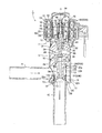
図1は、本発明に係るパイロット型制御弁の一実施形態を示す縦断面図である。 FIG. 1 is a longitudinal sectional view showing an embodiment of a pilot type control valve according to the present invention.
図示実施形態のパイロット型制御弁1は、マルチエアコン等の空調機において、室外機と室内機との間に配在するのに好適なもので、型式としては電動式パイロット型とされ、主弁5と該主弁5の上側に設けられた電動式パイロット弁7とからなっている。
The pilot
前記主弁5は、穴付き底部を有する円筒状の弁室筒体11とこの弁室筒体11の底部穴に溶接等により密封固定された弁座部材12とからなる弁本体10を有し、該弁本体10には、弁室13が形成され、また、周側部には高圧の冷媒を弁室13に導入するための入口導管(継手)41が連結され、底部(弁座部材12)には弁室13から冷媒を導出するための出口導管(継手)42が連結され、さらに、弁本体10(弁室筒体11)の上面開口を塞ぐように、台座状の画成部材32が溶接等により密封固定されている。
The
前記主弁5の弁座部材12には円錐面の主弁座14a付き主弁口14が設けられ、弁本体10(弁室筒体11)内における弁座部材12上には、断面逆凸字状のピストン型の主弁体20が摺動自在に嵌挿され、この主弁体20(の大径部20A)と前記画成部材32との間には背圧室33が画成されている。
The
前記主弁体20には、その下端部(小径部20B)に前記主弁座14aに接離する主弁部21が設けられ、また、主弁体20の大径部20Aには、前記弁室13と背圧室33とを連通するように小径の均圧孔24が形成され、また、大径部20Aと弁室筒体11との間にはシール材70が配在されている。
The
そして、前記主弁体20は、その大径部20Aの下端面部20aと前記弁座部材12との間に縮装された圧縮コイルばね25により常時開弁方向(上方)に付勢されている。詳細には、前記圧縮コイルばね25の上端部25aを受ける、前記主弁体20における大径部20Aの下端面部20a(上側ばね受け部)には、前記上端部25aの不所望な挙動を抑えるべく、該上端部25aが外挿される短円柱状の下向き突出部20bが設けられている。
The
また、前記弁座部材12は、主弁座14a付き主弁口14が形成されている小径円筒部12Aと、前記出口導管(継手)42が内挿連結されている大径円筒部12Bと、前記弁室筒体11の下端部が連結される段付き鍔状部12Cとを有し、該段付き鍔状部12Cの段丘面部(上面)12cが前記圧縮コイルばね25の下端部25bを受ける下側ばね受け部とされ、前記圧縮コイルばね25の下端部25bの不所望な挙動を抑えるべく、前記小径円筒部12Aに前記下端部25bが外挿されている。
The
さらに、前記主弁体20には、その中央を上下に貫通するようにパイロット通路28が形成されている。詳細には、前記主弁体20の上面部中央には、後述するパイロット弁体35の下端部に設けられたパイロット弁部36が接離するパイロット弁座部材22が圧入固定されている。パイロット弁座部材22は、パイロット弁座27a付きのパイロット弁口27が設けられ、このパイロット弁口27が前記パイロット通路28の上端部となっている。
Further, a
前記主弁5の上側に設けられた電動式パイロット弁7は、前記した画成部材32及びパイロット弁座27aに接離するパイロット弁部36を有する段付きニードル状のパイロット弁体35の他、前記画成部材32にその下端部が溶接により密封接合されたキャン34と、このキャン34の内周に所定の間隙をあけて配在されて、回転軸線O回りに回転せしめられるロータ55と、該ロータ55を回転駆動すべくキャン34に外装されたステータ50Aと、を備えている。
The
前記ステータ50Aは、磁性材からなるヨーク51と、このヨーク51にボビン52を介して巻回される上下のステータコイル53,53と、樹脂モールドカバー56とからなり、ロータ55とステータ50Aによりステッピングモータ50が構成されている。
The
前記キャン34は、ステンレス等の非磁性の金属板を素材として、深絞り加工等により天井を有する円筒状に形成されたもので、その下端部(開口端縁部)が、画成部材32の上部段差部に突き合わせ溶接により密封接合され、内部は気密状態に保たれている。
The
前記パイロット弁体35(のパイロット弁部36)をパイロット弁座27aに接離させる駆動機構は、パイロット弁体35が摺動自在に嵌挿された筒状のガイドブッシュ37とその外周に配在された下方開口の筒状の弁体ホルダ40とに形成されるねじ送り機構60とされる。すなわち、前記ガイドブッシュ37は、画成部材32にその下端部が圧入(又は螺合)固定されるとともに、その中央部付近に雄ねじ部62が形成され、前記弁体ホルダ40は、ガイドブッシュ37の雄ねじ部(固定ねじ部)62に螺合する雌ねじ部(移動ねじ部)61が形成され、また、その天底中央部にパイロット弁体35の上部小径部が相対回転及び相対移動可能に挿通せしめられている。パイロット弁体35の上部小径部の上端部は、弁体ホルダ40の天底上面(凹部)に乗せられたナット44に圧入固定されている。
The drive mechanism for bringing the pilot valve body 35 (the pilot valve portion 36) into and out of contact with the
また、前記パイロット弁体35は、弁体ホルダ40の天底とパイロット弁体35の中間段差部との間に縮装された緩衝用のコイルばね38によって常時下方に付勢されている。ガイドブッシュ37の側面には背圧室33とキャン34内の均圧を図る均圧孔37aが形成されている。
The
弁体ホルダ40の天底上には、コイルばねからなる復帰ばね45が設けられている。復帰ばね45は、ガイドブッシュ37の固定ねじ部62と弁体ホルダ40の移動ねじ部61との螺合が外れたときに、キャン34の天井に当接して固定ねじ部62と移動ねじ部61との螺合を復帰させるように働く。
A
弁体ホルダ40とロータ55とは支持リング43を介して結合されており、支持リング43に弁体ホルダ40の上部突部がかしめ固定され、これにより、ロータ55、支持リング43及び弁体ホルダ40が一体的に連結されている。
The
前記ガイドブッシュ37には、ストッパ機構の一方を構成する下ストッパ体(固定ストッパ)66が固着され、弁体ホルダ40にはストッパ機構の他方を構成する上ストッパ体(移動ストッパ)67が固着されている。
A lower stopper body (fixed stopper) 66 constituting one of the stopper mechanisms is fixed to the
そして、本実施形態では、前記主弁体20の大径部20Aの外径Daは、主弁口14の口径Dbの1.5〜3倍とされるとともに、前記ロータ55の外径Dcよりも大きくされ、また、主弁口14の口径は、パイロット弁口27の口径の3〜9倍とされ、パイロット弁口27の口径は、均圧孔24の孔径(最小部)より大きくされている。
In the present embodiment, the outer diameter Da of the large-
ここで、前記のように、主弁体20の大径部20Aの外径Daが主弁口14の口径Dbの1.5〜3倍とされている理由を説明する。すなわち、図6に、主弁5を開弁させるために必要なパイロット弁7(の弁口27の)開口面積が例示されているように、主弁体20の大径部20Aの外径Daが主弁口14の口径Dbの1.5倍程度未満では、その倍率が小さいほど、必要とされるパイロット弁の開口面積が急勾配で大きくなる。これは前記倍率が小さいほど、より大きなパイロット弁、より大きな開弁駆動力が必要となることを意味している。また、前記倍率が3倍を越えると、必要とされるパイロット弁の開口面積はさほど小さくはならなくなる。したがって、前記倍率を3倍以上にしても、パイロット弁のサイズや開弁駆動力をさほど小さくすることはできないので、無駄である。
Here, the reason why the outer diameter Da of the
また、主弁口14の口径は、パイロット弁口27の口径の3〜9倍とされることにより、小口径のパイロット弁7を開けば、それに応動して大口径の主弁5を開くことができるので、大口径の主弁5の開閉を小さな駆動力で行える。
The diameter of the
前記のような構成とされた本実施形態の電動式パイロット型のパイロット型制御弁1にあっては、前記主弁5が閉状態(図1、図2に示されるように、主弁体20の主弁部21が主弁座14aに着座している状態)にあり、かつ、電動式パイロット弁7が開状態(パイロット弁体35がパイロット弁座27aから離れている状態)のとき、ステッピングモータ50(ステータコイル53,53)に例えば順位相でパルス供給を行って、ロータ55をガイドブッシュ37に対して一方向に回転させると、ガイドブッシュ37の固定ねじ部62と弁体ホルダ40の移動ねじ部61とのねじ送りにより、弁体ホルダ40が下方に移動してパイロット弁体35のパイロット弁部36がパイロット弁座27aに着座圧接して閉状態となる。
In the electric pilot type pilot
この時点では、上ストッパ体67は未だ下ストッパ体66に当接しておらず、パイロット弁体35のパイロット弁部36がパイロット弁座27aに着座したまま弁体ホルダ40はさらに回転下降する。このときは、パイロット弁体35に対して弁体ホルダ40が下降するため、緩衝用のコイルばね38が圧縮せしめられることにより弁体ホルダ40の下降力は吸収される。その後、ロータ55がさらに回転して弁体ホルダ40が下降すると、上ストッパ体67が下ストッパ体66に衝接し、ステータコイル53,53に対するパルス供給が続行されても弁体ホルダ40の下降は強制的に停止される。
At this time, the
上記のように主弁5及び電動式パイロット弁7が閉状態(図1に示される状態)にあるときには、入口導管41から弁室13に導入された高圧の冷媒は、均圧孔24を介して背圧室33に導入され、背圧室33が高圧となるので、主弁体20の主弁部21が主弁座14aに強く押し付けられる。このときの、当該パイロット型制御弁1における弁開度=開口面積(主弁口14の実効開口面積+パイロット弁口27の実効開口面積)は、縦軸に開度=開口面積、横軸にパルス数(ロータ55の回転量)をとった図5に示される如くに、0(パルス数が0からTaまで)となり、弁室13から出口導管42へ流出する冷媒流量も0となる。
When the
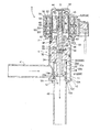
前記主弁5及び電動式パイロット弁7が閉状態(図1に示される状態)にあるときから、ステッピングモータ50(ステータコイル53,53)に例えば逆位相でパルス供給を行って、ロータ55をガイドブッシュ37に対して前記とは逆方向に回転させると、ガイドブッシュ37の固定ねじ部62と弁体ホルダ40の移動ねじ部61とのねじ送りにより、図2及び図5に示される如くに、パルス数(回転量)がTaとなったとき、弁体ホルダ40の上方移動に伴ってパイロット弁体35のパイロット弁部36がパイロット弁座27aから離れ始めてパイロット弁7が開き始め、図5に示される如くに、パルス数がTbになるまで、当該パイロット型制御弁1における弁開度=開口面積が徐々に微増して、背圧室33の冷媒がパイロット通路28を通じて出口導管42に流出し、背圧室33の圧力が徐々に減圧される。
From the time when the
そして、パルス数(回転量)がTbになると、図2に示される如くに、パイロット弁体35のパイロット弁部36がパイロット弁座27aから所定距離αだけ離れてパイロット弁口27の実効開口面積(当該パイロット型制御弁1における開口面積)がSaとなり、圧縮コイルばね25のばね力等の主弁体20を押し上げる力(開弁させる力)が主弁体20を押し下げる力(閉弁させる力)に打ち勝ち、主弁体20が押し上げられて、主弁部21が主弁座14aから離れ始め、主弁5が開き始める。
When the number of pulses (rotation amount) reaches Tb, as shown in FIG. 2, the
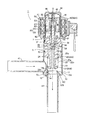
続いて、パルス数をさらに増加させていくと、パルス数がTcになるまで、図3に示される如くに、パイロット弁体35の上昇移動に追従するように、主弁体20が押し上げられる。詳細には、パイロット弁体35のパイロット弁部36がパイロット弁座27aから前記所定距離αだけ離れた状態、つまり、電動式パイロット弁7の開度を略一定に保った状態で、前記パイロット弁体35及び主弁体20が一緒に上方(開弁方向)に移動する。これにより、図5に示される如くに、パルス数(回転量)がTbからTcの間は、当該パイロット型制御弁1における開口面積(開度)が一定の勾配をもって滑らかに増加していく。すなわち、本実施形態では、パルス数がTbからTcになるまでは、パイロット弁体35のパイロット弁部36がパイロット弁座27aから所定距離αだけ離れた状態を維持したまま、パイロット弁体35と主弁体20とがパルス数(回転量)に対して同距離ずつ上昇するように、各部の寸法仕様等が設定されている。
Subsequently, when the number of pulses is further increased, the
そして、パルス数がTcになると、図4に示される如くに、主弁体20の上面ストッパ部29が画成部材32の下面に設けられた固定ストッパ39に接当し、主弁体20の上昇が阻止される。したがって、パルス数がTcを越えても、当該パイロット型制御弁1における弁開度=開口面積は、パルス数がTcのときのSbよりは大きくならず、このときの開度(最大開度)を維持することになる。
When the number of pulses reaches Tc, as shown in FIG. 4, the upper
以上のように、本実施形態のパイロット型制御弁1では、パイロット弁として、電磁式ではなく電動式のものを用いているので、パイロット弁7に供給するパルス数に応じて弁開度(開口面積)を滑らかに変化させることができるとともに、均圧時間を早くすることができる。そのため、弁開度(開口面積)を任意にかつきめ細かく調整することができるとともに、騒音の発生を効果的に抑えることができ、さらに、優れた応答性、動作安定性、制御特性等が得られる。また、主弁体20の大径部20Aの外径Daを主弁口14の口径Dbの1.5〜3倍とすることにより、パイロット弁7を必要最小限の大きさとすることができ、その結果、弁開閉に必要される消費電力等を抑えることができるとともに、ステッピングモータ50部分を含めた弁全体のコンパクト化を図れ、さらには、主弁体20の摺動が安定するので、より優れた制御特性及び動作安定性が得られる。
As described above, in the pilot
次に、本実施形態のパイロット型制御弁1を空調機の冷凍サイクルに組み込んだ例を図7を参照しながら説明する。ここで、空調機においては、暖房時に室外熱交換器に霜が付くと、暖房性能が低下するため、霜取りのため、デフロスト運転が不可欠であるが、デフロスト運転時は、暖房運転ができないため、室温が低下し、快適性が損なわれる。また、この種の冷凍サイクルでは、従来より流路切換弁として四方弁が使用されているが、通常の四方弁では、冷媒音の解消のため、コンプレッサを停止し、高低圧の均圧をとってから暖房→デフロスト、デフロスト→暖房の切換を行っているため、その切換に時間がかかる。したがって、均圧待ち時間を含めたデフロスト時間の短縮が望まれるところであり、かかる要望に応えるべく、図7に示される冷凍サイクル100では、前記四方弁に代えて本実施形態のパイロット型制御弁1が使用されている。
Next, an example in which the pilot
図7に示される冷凍サイクル100は、コンプレッサ110と、室内熱交換器130と、室外熱交換器150と、電動弁(膨張弁)140と、前記実施形態のパイロット型制御弁1(符号210、220)と、三方弁160とが備えられており、前記パイロット型制御弁210、220と三方弁160とで従来の冷凍サイクルに用いられていた四方弁の役目を果たすようになっている。前記パイロット型制御弁210、220においては、ポートa、ポートbがそれぞれ前記実施形態のパイロット型制御弁1における入口導管(継手)41、出口導管(継手)42となっており、また、三方弁160は、二つの入口ポートc、eと出口ポートdを有している(なお、この三方弁160自体は、本発明とは直接関係がないので、その詳細な説明はここでは省略する。三方弁160の詳細は、必要なら特開2004-92802号公報等を参照されたい)。
The
図7に示される冷凍サイクル100では、冷房時の冷媒の流れが実線矢印で示され、暖房時の冷媒の流れが破線矢印で示されている。
In the
すなわち、 (1)暖房時には、パイロット型制御弁210:開、パイロット型制御弁220:閉とされ、三方弁160のポートc→ポートd流れとなる。(2)暖房からデフロストへ切換途中1には、パイロット型制御弁210:開、パイロット型制御弁220:徐々に開弁し全開させる。このときには、三方弁160のポートeの圧力が上昇し、ポートcとポートeが同じ圧力となり、ポートc→ポートd、ポートe→ポートd流れが生じる。(3)暖房からデフロストへ切換途中2には、パイロット型制御弁210:徐々に閉弁し全閉させ、パイロット型制御弁220:開とする。このときには、三方弁160のポートcの圧力が低下することで、ポートe→ポートd流れとなる。(4)デフロスト運転時(冷媒の流れは冷房と同じ)は、パイロット型制御弁210:閉、パイロット型制御弁220:開とし、徐々に閉弁し全閉させる。(5)デフロストから暖房へ切換途中1には、パイロット型制御弁210:徐々に開弁し全開させ、パイロット型制御弁220:開とする。このときは、ポートcの圧力が上昇し、ポートeとポートcが同じ圧力となり、ポートe→ポートd、ポートc→ポートd流れが生じる。(6)デフロストから暖房へ切換途中2には、パイロット型制御弁210:開、パイロット型制御弁220:徐々に開弁し全開させる。このときには、ポートeの圧力が低下することでポートc→ポートd流れとなる。
That is, (1) During heating, the pilot
このように、前記実施形態のパイロット型制御弁1(210、220)を使用することにより、弁の開閉を任意に調整、すなわち、開口面積=流量を徐々に変化させることができるので、コンプレッサ110を停止させることなく、暖房→デフロスト、デフロスト→暖房の切換が可能となり、冬場のデフロスト時間の短縮が可能となる。 Thus, by using the pilot type control valve 1 (210, 220) of the above embodiment, the opening and closing of the valve can be arbitrarily adjusted, that is, the opening area = flow rate can be gradually changed. It is possible to switch between heating → defrost and defrost → heating without stopping the operation, and the defrost time in winter can be shortened.
次に、前記した図1〜図4に示されるパイロット型制御弁1の改良例を、図8(A)、(B)を参照しながら説明する。なお、図8に示される改良例のパイロット型制御弁1’において、前記パイロット型制御弁1の各部に対応する部分には同一の符号を付して重複説明を省略し、以下においては相違点を重点的に説明する。
Next, an improved example of the pilot
図8に示されるパイロット型制御弁1’は、前記実施形態のパイロット型制御弁1に対し、圧縮コイルばね25の上端部25a及び下端部25bの不所望な挙動を抑えて動作不良を起こし難くしたものである。
The pilot
すなわち、本改良例では、前記した実施形態と同様に、前記弁座部材12の段丘面部12cは、前記圧縮コイルばね25の下端部25bを受ける下側ばね受け部とされるとともに、該下端部25bは、その不所望な挙動を抑えるべく、前記弁座部材12の小径円筒部12A’に所定の態様(後述)で外挿されており、また、前記主弁体20の大径部20Aの下端面部20a(上側ばね受け部)には、前記圧縮コイルばね25の上端部25aの不所望な挙動を抑えるべく、該上端部25aが外挿される所定形状(後述)の下向き突出部20b’(前記実施形態の下向き突出部20bは短円柱状)が設けられている。
That is, in this improved example, the
そして、本改良例では、図8(B)を参照すればよくわかるように、前記圧縮コイルばね25の下端部25bが外挿される前記弁座部材12の小径円筒部12A’の外周部に、前記下端部25bを固定保持する係止部としての、前記下端部25bが螺合せしめられる2〜3ピッチの雄ねじ状部12dが設けられている。
In this improved example, as can be understood by referring to FIG. 8B, the outer peripheral portion of the small-diameter
また、前記主弁体20の下向き突出部20b’には、短円柱状部20dに連なって円錐面部20cが設けられている。
Further, the downwardly protruding
このように、弁座部材12の小径円筒部12A’外周部に、圧縮コイルばね25の下端部25bを固定保持するための雄ねじ状部12dが設けられることにより、圧縮コイルばね25の下端部25bが前記弁座部材12の段丘面部12cから浮き上がる、前記小径円筒部12A’から抜け出る等の不所望な挙動を起こし難くなり、その結果、動作不良を確実に防止することができるとともに、一層優れた動作安定性、制御特性等が得られ、さらには、騒音低減化等も図ることができる。
As described above, the male screw-
また、前記主弁体20の下向き突出部20b’に円錐面部20cが設けられていることにより、前記圧縮コイルばね25の上端部25aが前記主弁体20の大径部20Aの下端面部20a(ばね受け部)から離れて下向き突出部20b’上に乗り上げても、直ちに元の下端面部20a(ばね受け部)に戻すことができ、これにより、動作不良を一層確実に防止することができる。
Further, since the
1 パイロット型制御弁
5 主弁
7 電動式パイロット弁
10 弁本体
12 弁座部材
12A 小径円筒部
12B 大径円筒部
12C 段差鍔状部
12c 段丘面部(下側ばね受け部)
12d 雄ねじ状部(係止部)
13 弁室
14 主弁口
14a 主弁座
20 主弁体
20A 大径部
20B 小径部
20a 下端面部(上側ばね受け部)
20b 下向き突出部
20c 円錐面部
24 均圧孔
25 圧縮コイルばね
27 パイロット弁口
27a パイロット弁座
28 パイロット通路
32 画成部材
33 背圧室
35 パイロット弁体
40 弁体ホルダ
50 ステッピングモータ
55 ロータ
DESCRIPTION OF
12d Male thread (locking part)
13
20b downward projecting
Claims (10)
前記主弁は、流体が導入導出される弁室が形成された弁本体と、該弁本体内に摺動自在に嵌挿されて前記弁本体に設けられた主弁口を開閉する大径部と小径部とを有する断面逆凸字状のピストン型の主弁体と、を有し、
前記電動式パイロット弁は、前記弁本体の上面開口を塞ぐように取り付けられて前記主弁体との間に背圧室を画成する画成部材と、前記主弁体に設けられたパイロット弁口を開閉するパイロット弁体と、を有し、
前記主弁には、前記弁室と前記背圧室とを連通する均圧通路が設けられるとともに、前記主弁体が圧縮コイルばねにより常時開弁方向に付勢されており、かつ、前記パイロット弁体の開弁方向の移動に追従するように、前記主弁体が開弁方向に移動するようにされており、
前記弁本体は、前記主弁体が摺動自在に嵌挿される弁室筒体と、該弁室筒体の下部に設けられた段付き円筒状部を持つ弁座部材と、を有し、前記圧縮コイルばねは、前記主弁体の大径部に設けられた下向き突出部付き下端面部と前記弁座部材の段丘面部との間に介装されるとともに、その上下端部が前記主弁体の下向き突出部と前記弁座部材の円筒状部にそれぞれ外挿されており、
前記主弁口の口径は、前記パイロット弁口の口径の3〜9倍とされていることを特徴とするパイロット型制御弁。 A pilot type control valve having a main valve and an electric pilot valve,
The main valve includes a valve body in which a valve chamber into which fluid is introduced and led is formed, and a large-diameter portion that is slidably inserted into the valve body and opens and closes a main valve port provided in the valve body. And a piston-type main valve body having a reverse convex shape in cross section having a small-diameter portion,
The motor-operated pilot valve is mounted so as to close an upper surface opening of the valve body and defines a back pressure chamber between the main valve body and a pilot valve provided in the main valve body A pilot valve body for opening and closing the mouth,
The main valve is provided with a pressure equalizing passage communicating the valve chamber and the back pressure chamber, the main valve body is always urged in a valve opening direction by a compression coil spring, and the pilot The main valve body is adapted to move in the valve opening direction so as to follow the movement of the valve body in the valve opening direction ,
The valve body includes a valve chamber cylinder into which the main valve body is slidably fitted, and a valve seat member having a stepped cylindrical portion provided at a lower portion of the valve chamber cylinder, The compression coil spring is interposed between a lower end surface portion with a downward projecting portion provided in a large diameter portion of the main valve body and a terrace surface portion of the valve seat member, and upper and lower end portions thereof are the main valve. Each of which is extrapolated to the downward projecting part of the body and the cylindrical part of the valve seat member,
A pilot type control valve characterized in that the diameter of the main valve port is 3 to 9 times the diameter of the pilot valve port .
前記主弁体は、前記パイロット弁体の開弁方向の移動に追従するように、前記主弁体が開弁方向に移動するようにされていることを特徴とする請求項1に記載のパイロット型制御弁。2. The pilot according to claim 1, wherein the main valve body is configured to move in the valve opening direction so as to follow movement of the pilot valve body in the valve opening direction. Mold control valve.
Priority Applications (1)
| Application Number | Priority Date | Filing Date | Title |
|---|---|---|---|
| JP2006333412A JP5019862B2 (en) | 2006-08-07 | 2006-12-11 | Pilot type control valve |
Applications Claiming Priority (3)
| Application Number | Priority Date | Filing Date | Title |
|---|---|---|---|
| JP2006214365 | 2006-08-07 | ||
| JP2006214365 | 2006-08-07 | ||
| JP2006333412A JP5019862B2 (en) | 2006-08-07 | 2006-12-11 | Pilot type control valve |
Publications (3)
| Publication Number | Publication Date |
|---|---|
| JP2008064301A JP2008064301A (en) | 2008-03-21 |
| JP2008064301A5 JP2008064301A5 (en) | 2010-01-28 |
| JP5019862B2 true JP5019862B2 (en) | 2012-09-05 |
Family
ID=39287181
Family Applications (1)
| Application Number | Title | Priority Date | Filing Date |
|---|---|---|---|
| JP2006333412A Active JP5019862B2 (en) | 2006-08-07 | 2006-12-11 | Pilot type control valve |
Country Status (1)
| Country | Link |
|---|---|
| JP (1) | JP5019862B2 (en) |
Families Citing this family (11)
| Publication number | Priority date | Publication date | Assignee | Title |
|---|---|---|---|---|
| JP2011089732A (en) * | 2009-10-26 | 2011-05-06 | Fuji Koki Corp | Heat pump device |
| CN102052468A (en) * | 2009-11-01 | 2011-05-11 | 浙江三花制冷集团有限公司 | Flow path switch control device |
| JP5726506B2 (en) * | 2010-12-21 | 2015-06-03 | 株式会社不二工機 | Electric pilot type control valve |
| CN102704889B (en) * | 2012-06-24 | 2014-07-02 | 北京众博达石油科技有限公司 | Pilot-operated type solenoid valve for gas well wellhead and valve plug lifting mechanism |
| JP6031931B2 (en) * | 2012-10-03 | 2016-11-24 | 株式会社デンソー | Refrigeration cycle equipment |
| CN104930252A (en) * | 2014-03-21 | 2015-09-23 | 浙江三花股份有限公司 | Pilot-operated type control valve |
| CN104819330A (en) * | 2015-04-01 | 2015-08-05 | 浙江三花股份有限公司 | Pilot-operated type solenoid valve and combination method therefor |
| CN113677919B (en) * | 2019-02-21 | 2023-09-05 | 株式会社不二工机 | Flow control valve and method of assembling the same |
| CN110671506A (en) * | 2019-10-17 | 2020-01-10 | 太原纳新食品有限公司 | Lock nut type double-seal ring valve |
| JP2021179240A (en) * | 2020-05-15 | 2021-11-18 | 株式会社鷺宮製作所 | Motor-operated valve and refrigeration cycle system |
| CN111637230B (en) * | 2020-05-22 | 2021-03-30 | 杭州易超新能源汽车科技有限公司 | Novel combination valve |
Family Cites Families (5)
| Publication number | Priority date | Publication date | Assignee | Title |
|---|---|---|---|---|
| JPS58123976U (en) * | 1982-02-17 | 1983-08-23 | 株式会社鷺宮製作所 | Reversible solenoid valve |
| JPS63199980A (en) * | 1987-02-17 | 1988-08-18 | Saginomiya Seisakusho Inc | Pilot proportional valve |
| JPH0665915B2 (en) * | 1987-03-27 | 1994-08-24 | 株式会社鷺宮製作所 | Reversible electric expansion valve |
| JP2898906B2 (en) * | 1995-06-29 | 1999-06-02 | 株式会社不二工機 | Electric flow control valve |
| JP5060689B2 (en) * | 2001-04-13 | 2012-10-31 | 株式会社鷺宮製作所 | Flow control valve and control device for flow control valve |
-
2006
- 2006-12-11 JP JP2006333412A patent/JP5019862B2/en active Active
Also Published As
| Publication number | Publication date |
|---|---|
| JP2008064301A (en) | 2008-03-21 |
Similar Documents
| Publication | Publication Date | Title |
|---|---|---|
| JP5019862B2 (en) | Pilot type control valve | |
| CN110094514B (en) | Electric valve and refrigeration cycle system | |
| KR101342780B1 (en) | Pilot type control valve | |
| JP5022120B2 (en) | Motorized valves for air conditioning systems | |
| JP6194157B2 (en) | Motorized valve | |
| JP5726426B2 (en) | Three-way electric valve and heat pump device equipped with the valve | |
| JP4812601B2 (en) | Motorized valve | |
| US9194510B2 (en) | Composite valve | |
| CN110107695B (en) | Electric valve and refrigeration cycle system | |
| JP5572330B2 (en) | Motorized valve | |
| JP4570484B2 (en) | Composite valve, heat pump type air conditioner and control method thereof | |
| US20120091375A1 (en) | Electrically operated valve | |
| JP6209231B2 (en) | Motorized valve | |
| JP5657424B2 (en) | Motorized valve | |
| JP2008121711A (en) | Flow control valve | |
| US20120211683A1 (en) | Valve apparatus | |
| JP4056378B2 (en) | Differential pressure valve | |
| JP2022095807A (en) | Motor-operated valve and refrigerating cycle system | |
| JP4653518B2 (en) | Three-way valve | |
| JP5881452B2 (en) | Compound valve | |
| JP2010249247A (en) | Motor-operated valve and refrigeration cycle using the same | |
| JP5881451B2 (en) | Compound valve | |
| JP2017044347A (en) | Motor valve | |
| JP2020169661A (en) | Electric valve and refrigeration cycle system | |
| CN113217640B (en) | Electric valve and refrigeration cycle system |
Legal Events
| Date | Code | Title | Description |
|---|---|---|---|
| A521 | Request for written amendment filed |
Free format text: JAPANESE INTERMEDIATE CODE: A523 Effective date: 20091208 |
|
| A621 | Written request for application examination |
Free format text: JAPANESE INTERMEDIATE CODE: A621 Effective date: 20091208 |
|
| A977 | Report on retrieval |
Free format text: JAPANESE INTERMEDIATE CODE: A971007 Effective date: 20111027 |
|
| A131 | Notification of reasons for refusal |
Free format text: JAPANESE INTERMEDIATE CODE: A131 Effective date: 20111122 |
|
| A521 | Request for written amendment filed |
Free format text: JAPANESE INTERMEDIATE CODE: A523 Effective date: 20120123 |
|
| TRDD | Decision of grant or rejection written | ||
| A01 | Written decision to grant a patent or to grant a registration (utility model) |
Free format text: JAPANESE INTERMEDIATE CODE: A01 Effective date: 20120605 |
|
| A01 | Written decision to grant a patent or to grant a registration (utility model) |
Free format text: JAPANESE INTERMEDIATE CODE: A01 |
|
| A61 | First payment of annual fees (during grant procedure) |
Free format text: JAPANESE INTERMEDIATE CODE: A61 Effective date: 20120612 |
|
| R150 | Certificate of patent or registration of utility model |
Ref document number: 5019862 Country of ref document: JP Free format text: JAPANESE INTERMEDIATE CODE: R150 Free format text: JAPANESE INTERMEDIATE CODE: R150 |
|
| FPAY | Renewal fee payment (event date is renewal date of database) |
Free format text: PAYMENT UNTIL: 20150622 Year of fee payment: 3 |
|
| R250 | Receipt of annual fees |
Free format text: JAPANESE INTERMEDIATE CODE: R250 |
|
| R250 | Receipt of annual fees |
Free format text: JAPANESE INTERMEDIATE CODE: R250 |
|
| R250 | Receipt of annual fees |
Free format text: JAPANESE INTERMEDIATE CODE: R250 |
|
| R250 | Receipt of annual fees |
Free format text: JAPANESE INTERMEDIATE CODE: R250 |
|
| R250 | Receipt of annual fees |
Free format text: JAPANESE INTERMEDIATE CODE: R250 |
|
| R250 | Receipt of annual fees |
Free format text: JAPANESE INTERMEDIATE CODE: R250 |
|
| R250 | Receipt of annual fees |
Free format text: JAPANESE INTERMEDIATE CODE: R250 |