JP5017328B2 - Tomographic imaging apparatus, control method therefor, program, and storage medium - Google Patents
Tomographic imaging apparatus, control method therefor, program, and storage medium Download PDFInfo
- Publication number
- JP5017328B2 JP5017328B2 JP2009186779A JP2009186779A JP5017328B2 JP 5017328 B2 JP5017328 B2 JP 5017328B2 JP 2009186779 A JP2009186779 A JP 2009186779A JP 2009186779 A JP2009186779 A JP 2009186779A JP 5017328 B2 JP5017328 B2 JP 5017328B2
- Authority
- JP
- Japan
- Prior art keywords
- tomographic
- tomographic image
- retinal layer
- measurement range
- imaging apparatus
- Prior art date
- Legal status (The legal status is an assumption and is not a legal conclusion. Google has not performed a legal analysis and makes no representation as to the accuracy of the status listed.)
- Expired - Fee Related
Links
- 238000000034 method Methods 0.000 title claims description 92
- 238000003384 imaging method Methods 0.000 title claims description 52
- 230000002207 retinal effect Effects 0.000 claims description 99
- 238000005259 measurement Methods 0.000 claims description 91
- 238000012014 optical coherence tomography Methods 0.000 claims description 27
- 238000000605 extraction Methods 0.000 claims description 9
- 238000004590 computer program Methods 0.000 claims description 6
- 238000002059 diagnostic imaging Methods 0.000 claims description 6
- 239000000284 extract Substances 0.000 claims description 3
- 230000003287 optical effect Effects 0.000 claims 1
- 210000003583 retinal pigment epithelium Anatomy 0.000 description 33
- 238000001514 detection method Methods 0.000 description 29
- 210000001525 retina Anatomy 0.000 description 16
- 210000004379 membrane Anatomy 0.000 description 15
- 239000012528 membrane Substances 0.000 description 15
- 238000010586 diagram Methods 0.000 description 13
- 238000012545 processing Methods 0.000 description 9
- 210000005081 epithelial layer Anatomy 0.000 description 3
- 238000010191 image analysis Methods 0.000 description 3
- 239000000790 retinal pigment Substances 0.000 description 3
- 238000012790 confirmation Methods 0.000 description 2
- 238000003745 diagnosis Methods 0.000 description 2
- 201000010099 disease Diseases 0.000 description 2
- 208000037265 diseases, disorders, signs and symptoms Diseases 0.000 description 2
- 238000001228 spectrum Methods 0.000 description 2
- 238000012360 testing method Methods 0.000 description 2
- 201000004569 Blindness Diseases 0.000 description 1
- 208000010412 Glaucoma Diseases 0.000 description 1
- 206010064930 age-related macular degeneration Diseases 0.000 description 1
- 230000000694 effects Effects 0.000 description 1
- 239000004973 liquid crystal related substance Substances 0.000 description 1
- 208000002780 macular degeneration Diseases 0.000 description 1
- 210000004126 nerve fiber Anatomy 0.000 description 1
- 108091008695 photoreceptors Proteins 0.000 description 1
- 238000005070 sampling Methods 0.000 description 1
Images


Classifications
-
- A—HUMAN NECESSITIES
- A61—MEDICAL OR VETERINARY SCIENCE; HYGIENE
- A61B—DIAGNOSIS; SURGERY; IDENTIFICATION
- A61B3/00—Apparatus for testing the eyes; Instruments for examining the eyes
- A61B3/10—Objective types, i.e. instruments for examining the eyes independent of the patients' perceptions or reactions
- A61B3/102—Objective types, i.e. instruments for examining the eyes independent of the patients' perceptions or reactions for optical coherence tomography [OCT]
-
- A—HUMAN NECESSITIES
- A61—MEDICAL OR VETERINARY SCIENCE; HYGIENE
- A61B—DIAGNOSIS; SURGERY; IDENTIFICATION
- A61B3/00—Apparatus for testing the eyes; Instruments for examining the eyes
- A61B3/10—Objective types, i.e. instruments for examining the eyes independent of the patients' perceptions or reactions
- A61B3/12—Objective types, i.e. instruments for examining the eyes independent of the patients' perceptions or reactions for looking at the eye fundus, e.g. ophthalmoscopes
-
- G—PHYSICS
- G01—MEASURING; TESTING
- G01N—INVESTIGATING OR ANALYSING MATERIALS BY DETERMINING THEIR CHEMICAL OR PHYSICAL PROPERTIES
- G01N21/00—Investigating or analysing materials by the use of optical means, i.e. using sub-millimetre waves, infrared, visible or ultraviolet light
- G01N21/62—Systems in which the material investigated is excited whereby it emits light or causes a change in wavelength of the incident light
- G01N21/71—Systems in which the material investigated is excited whereby it emits light or causes a change in wavelength of the incident light thermally excited
Description
本発明は、断層像撮像装置およびその制御方法に関し、特に眼科診療等に用いられる断層像撮像装置およびその制御方法に関する。 The present invention relates to a tomographic imaging apparatus and a control method thereof, and more particularly to a tomographic imaging apparatus used for ophthalmic medical treatment and the control method thereof.
光干渉断層計(OCT;Optical Coherence Tomography)などを利用した眼部断層像撮像装置は、網膜層内部の状態を3次元的に観察することが可能であり、疾病の診断をより的確に行うのに有用であることから近年注目を集めている。 An ocular tomographic imaging apparatus using an optical coherence tomography (OCT) or the like is capable of three-dimensionally observing the state inside the retinal layer and more accurately diagnoses the disease. It has attracted attention in recent years because of its usefulness.
図5に、眼底におけるOCTの計測範囲及び対応する網膜の断層像の模式図を示す。図5において、501は眼底像、RXYは眼底の平面(x軸:水平方向、y軸:垂直方向)におけるOCTの2次元の計測範囲を表す。図5の例では、RXYは矩形領域である。そして、T1〜Tnは計測範囲RXYに対して網膜の奥行き方向を撮像して得られる黄斑部の2次元断層像(B−Scan像)である。一つの断層像は、複数の網膜の奥行き方向をスキャンするスキャンライン(以降A−スキャンラインと呼ぶ)で構成される。z軸は、このA−スキャンの方向を表し、RZはz軸方向におけるOCTの奥行き方向の1次元の計測範囲を表す。OCTの撮像では、眼底に対して設定された計測範囲RXYを順にラスタスキャンする(x軸方向のスキャンを主走査、y軸方向のスキャンを副走査と呼ぶ)ことで、これらの断層像群として3次元データを一度に取得できる。また、Mは中心窩、Aは内境界膜、Bは網膜色素上皮層境界を表す。内境界膜Aから網膜色素上皮層境界Bまでの間の網膜層の領域は、失明の主な原因である緑内障や加齢黄斑変性などの疾患の解剖的特徴が現れるため、OCTの断層像を用いた診断に非常に役立つ。そのため、断層像を撮像する際は、この領域が断層像の深さ方向の上端と下端から途切れないように撮像を行うことが重要である。 FIG. 5 shows a schematic diagram of an OCT measurement range on the fundus and a corresponding tomographic image of the retina. In FIG. 5, 501 represents a fundus image, and R XY represents a two-dimensional measurement range of OCT on the fundus plane (x axis: horizontal direction, y axis: vertical direction). In the example of FIG. 5, RXY is a rectangular area. T 1 to T n are two-dimensional tomographic images (B-Scan images) of the macular portion obtained by imaging the depth direction of the retina with respect to the measurement range R XY . One tomographic image is composed of scan lines (hereinafter referred to as A-scan lines) for scanning the depth direction of a plurality of retinas. The z-axis represents the direction of this A-scan, and R Z represents the one-dimensional measurement range in the OCT depth direction in the z-axis direction. The imaging OCT, sequentially raster scan set measurement range R XY respect fundus (x-axis direction of the scan in the main scanning is called a scan in the y-axis direction and sub-scanning) it is, these tomographic images group 3D data can be acquired at once. M represents the fovea, A represents the inner limiting membrane, and B represents the retinal pigment epithelial layer boundary. Since the anatomical features of diseases such as glaucoma and age-related macular degeneration that are the main causes of blindness appear in the region of the retinal layer between the inner boundary membrane A and the retinal pigment epithelium layer boundary B, a tomogram of OCT Very useful for the diagnosis used. Therefore, when capturing a tomographic image, it is important to capture the region so that this region is not interrupted from the upper end and the lower end in the depth direction of the tomographic image.
一般的なOCT装置では、3次元データを撮像する前の被験眼観察時に、計測範囲RXYの中心を通る断層像のみを、1枚若しくは数枚実時間で取得し、表示するようにしている。こうすることで、断層像に網膜層の領域が収まっているかを目視で確認し、撮像する位置を適切に調整していた。また、特許文献1では、被験眼観察時に取得した1枚の断層像を解析して網膜層が写っているかどうかを判別することで、断層像に網膜層が写るように自動的に撮像する位置を調整する技術が紹介されている。 In a general OCT apparatus, only one or several tomographic images passing through the center of the measurement range RXY are acquired and displayed in real time during observation of the subject's eye before imaging three-dimensional data. . By doing this, it was visually confirmed whether or not the area of the retinal layer was contained in the tomographic image, and the imaging position was adjusted appropriately. Further, in Patent Document 1, by analyzing one tomographic image acquired at the time of observing the subject eye and determining whether or not the retinal layer is captured, a position where the retinal layer is automatically captured so that the retinal layer is captured in the tomographic image. The technology to adjust is introduced.
しかしながら、上記の手法では、撮影者或いはコンピュータが計測範囲RXYの中心を通る数枚の断層像しか認識しないため、被験眼観察時に、その後撮像する3次元データに網膜層が適切に収まるかどうかを判別することができなかった。特に網膜層の湾曲が激しい近視眼を撮像する場合、被験眼観察時に計測範囲RXYの中心を通る断層像に網膜層が収まっていたとしても、中心から離れた位置の断層像では網膜層が適切に収まらなくなる可能性があった。そのような場合、撮像は失敗となり、結果として断層像を撮り直さなければならなかった。 However, if the above method, since the photographer or is not recognized by the computer only a few tomographic image passing through the center of the measurement range R XY, when tested eye observation, retinal layers fit properly in the three-dimensional data to be subsequently captured Could not be determined. In particular, when imaging a myopic eye in which the curvature of the retinal layer is severe, even if the retinal layer is contained in a tomographic image that passes through the center of the measurement range RXY when observing the subject eye, the retinal layer is appropriate in the tomographic image at a position away from the center May not fit in. In such a case, imaging failed, and as a result, a tomographic image had to be taken again.
本発明は上記の課題に鑑みてなされたものであり、光干渉断層計を用いた撮像装置において、設定された計測範囲において断層像の深さ方向の撮影位置を容易且つ適切に設定可能にすることを目的とする。 The present invention has been made in view of the above problems, and in an imaging apparatus using an optical coherence tomography, it is possible to easily and appropriately set the imaging position in the depth direction of a tomographic image within a set measurement range. For the purpose.
上記の目的を達成するための、本発明の一態様による断層像撮像装置の制御方法は、
光干渉断層計により眼底の断層像を撮影する断層像撮像装置の制御方法であって、
設定手段が、眼底における、断層像を撮影すべき計測範囲を設定する設定工程と、
取得手段が、前記光干渉断層計を用いて、前記計測範囲の、診断用の撮影よりも少ない予め定められた複数の位置で断層像を取得する取得工程と、
表示制御手段が、前記取得工程で取得された断層像を、リアルタイムに、表示装置の画面に並べて表示させる表示制御工程とを有する。
In order to achieve the above object, a method for controlling a tomographic imaging apparatus according to an aspect of the present invention includes:
A method for controlling a tomographic imaging apparatus that takes a tomographic image of the fundus using an optical coherence tomography,
A setting step in which the setting means sets a measurement range in which tomographic images are to be taken on the fundus;
An acquisition step for acquiring tomographic images at a plurality of predetermined positions less than diagnostic imaging in the measurement range using the optical coherence tomography;
The display control means includes a display control step of displaying the tomographic images acquired in the acquisition step side by side on the screen of the display device in real time.
本発明によれば、光干渉断層計を用いた撮影装置において、設定された計測範囲において断層像の深さ方向の撮影位置を容易且つ適切に設定することが可能になる。 According to the present invention, in an imaging apparatus using an optical coherence tomography, it is possible to easily and appropriately set an imaging position in the depth direction of a tomographic image within a set measurement range.
[第1実施形態]
本実施形態は、光干渉断層計(以下、OCT)により被験眼の断層画像を撮影する際に、計測範囲において複数部位のスキャンを繰り返しながら表示することにより、計測対象が撮影画像内に収まるように調整することを可能にしたものである。より具体的には、本実施形態の断層像撮像装置は、OCTで診断用の3次元データの撮像を行う前の被験眼観察時に、被検眼の計測範囲RXYの中央と端部の位置の断層像を取得し、それらを実時間で確認画面上に並べて表示する。このとき、網膜の3次元形状は楕円体に近似できるため、計測範囲RXYの中心から外側に向かうほど、中心に対する網膜の奥行き(z軸)方向の位置の差が単調に大きくなる性質を有する。この性質により、計測範囲RXYの中央と端部の位置における断層像の状態を参照可能にすることで、撮影者にその後撮像する3次元データに網膜層が収まるかどうかを常に認識させることを可能にする。ここで、計測範囲RXYの中央と端部の位置とは、それぞれ、計測範囲RXYの中心を通る位置及び、計測範囲RXYの最も外側の端の領域を含む位置を表す。以下に具体例を幾つか示す。
[First Embodiment]
In the present embodiment, when a tomographic image of the subject eye is captured by an optical coherence tomography (hereinafter referred to as OCT), the measurement target is included in the captured image by displaying while repeatedly scanning a plurality of parts in the measurement range. It is possible to adjust to. More specifically, the tomographic image capturing apparatus of this embodiment, during the previous test eye observation for imaging a three-dimensional data for diagnosis OCT, the position of the center and the end portion of the eye of the measurement range R XY Tomographic images are acquired and displayed side by side on the confirmation screen in real time. At this time, since the three-dimensional shape of the retina can be approximated to an ellipsoid, the difference in the position of the retina in the depth (z-axis) direction with respect to the center increases monotonously from the center of the measurement range RXY. . This property allows the photographer to always recognize whether or not the retinal layer fits in the three-dimensional data that is subsequently captured by making it possible to refer to the state of the tomographic image at the center and end positions of the measurement range RXY. enable. Here, the position of the center and the end of the measurement range R XY, respectively, position and through the center of the measurement range R XY, represents the position including a region of the outermost end of the measurement range R XY. Some specific examples are shown below.
図13は、計測範囲RXYに対応する中央と端部の位置を示す図である。図13の(a)及び(b)は、計測範囲RXYが矩形である場合の中央と端部の位置を示す2種類の図である。(c)及び(d)は、計測範囲RXYが平行四辺形である場合の中央と端部の位置を示す2種類の図である。(e)及び(f)は、計測範囲RXYが円形である場合の中央と端部の位置を示す2種類の図である。(a)〜(f)の各図における1301は眼底像、RXYは2次元の計測範囲である。また、1302、1306、1310、1314、1318、1321は計測範囲RXYの中央の位置を示す。1303と1304、1307と1308、1311と1312、1315と1316、1319、1322は端部の位置を示す。また、(c)及び(d)におけるP1、P2、P3、P4は計測範囲RXYの4つの頂点を示す。このとき、各図における中央と端部の位置は、全て上記の定義を満たす位置である。計測範囲RXYが矩形の場合は、中央と端部の位置をそれぞれ、(a)のように図中のx軸と平行な線分としても良いし、(b)のようにy軸と平行な線分としても良い。計測範囲RXYが平行四辺形の場合は、中央と端部の位置をそれぞれ、(c)のように図中の辺P1P4と平行な線分としても良いし、(d)のように図中の辺P1P2と平行な線分としても良い。計測範囲RXYが円形の場合は、計測範囲RXYの中央の位置をそれぞれ、(e)のように図中のx軸と平行な線分としても良いし、(f)のようにy軸と平行な線分としても良い。端部の位置は、計測範囲RXYの円周の位置とする。すなわち、円周状に走査して得られた断層像を用いる。以下に説明する本実施形態では、一例として図13の(a)の場合を具体的に説明するが、計測範囲の形状及び中央と端部の位置はこの例に限定されない。 FIG. 13 is a diagram illustrating the positions of the center and the end corresponding to the measurement range RXY . FIGS. 13A and 13B are two types of diagrams showing the positions of the center and the end when the measurement range RXY is rectangular. (C) And (d) is 2 types of figures which show the position of the center and edge part in case measurement range RXY is a parallelogram. (E) and (f) are two types of diagrams showing the positions of the center and the end when the measurement range RXY is circular. In each of the drawings (a) to (f), 1301 is a fundus image, and RXY is a two-dimensional measurement range. Further, 1302,1306,1310,1314,1318,1321 indicates the center position of the measurement range R XY. Reference numerals 1303 and 1304, 1307 and 1308, 1311 and 1312, 1315 and 1316, 1319, and 1322 indicate end positions. Further, P 1 , P 2 , P 3 , and P 4 in (c) and (d) indicate four vertices of the measurement range R XY . At this time, the positions of the center and the end in each figure are all positions that satisfy the above definition. When the measurement range RXY is rectangular, the positions of the center and the end may be respectively a line segment parallel to the x axis in the figure as shown in (a), or parallel to the y axis as shown in (b). It may be a straight line segment. When the measurement range R XY is a parallelogram, the center and end positions may be line segments parallel to the side P 1 P 4 in the figure as shown in (c), or as shown in (d). Alternatively, a line segment parallel to the side P 1 P 2 in the drawing may be used. When the measurement range R XY is circular, the center position of the measurement range R XY may be a line segment parallel to the x axis in the drawing as shown in (e), or the y axis as shown in (f). It is good also as a line segment parallel to. The position of the end is the circumferential position of the measurement range RXY . That is, a tomographic image obtained by scanning the circumference is used. In the present embodiment described below, the case of FIG. 13A is specifically described as an example, but the shape of the measurement range and the positions of the center and the end are not limited to this example.
そして、中央部および両端部の断層像をリアルタイムで表示することにより、ユーザは奥行き方向の計測範囲から網膜層がはみ出しているか(奥行き方向に関して途切れているか)どうかを容易に判断できる。また、リアルタイムで表示される中央部および両端部の断層像をみながらOCTの参照ミラーを移動することが出来るため、参照ミラーを容易に適切な位置にセットすることができる。また、上記の断層像から網膜層が、計測範囲の奥行き方向において途切れているかを検知し、途切れている場合には、その旨を警告提示することで、撮影者が網膜層の途切れを認識する支援を行うようにする。ここで、網膜層の奥行き方向の途切れは、例えば、断層像の上辺または下辺に対して網膜層が接するまたは交差するかを判断することで検出される。さらに、断層像における網膜層の位置を認識し、網膜層が断層像から途切れないようにz軸方向の計測深度を自動調整することを可能とし、撮影者の負担を軽減しかつ撮像ミスを防ぐ。以下に具体例を説明する。 Then, by displaying the tomographic images at the center and both ends in real time, the user can easily determine whether or not the retinal layer protrudes from the measurement range in the depth direction (discontinuity in the depth direction). In addition, since the OCT reference mirror can be moved while viewing the tomographic images at the center and both ends displayed in real time, the reference mirror can be easily set at an appropriate position. Further, it is detected from the above tomographic image whether or not the retinal layer is interrupted in the depth direction of the measurement range, and when it is interrupted, the photographer recognizes the disconnection of the retinal layer by presenting a warning to that effect. Try to provide support. Here, the discontinuity in the depth direction of the retinal layer is detected, for example, by determining whether the retinal layer is in contact with or intersects with the upper side or the lower side of the tomographic image. Furthermore, the position of the retinal layer in the tomographic image is recognized, and the measurement depth in the z-axis direction can be automatically adjusted so that the retinal layer is not interrupted from the tomographic image, reducing the burden on the photographer and preventing imaging errors. . A specific example will be described below.
図14は、網膜層の途切れを説明する図である。図14の(a)、(b)はそれぞれ、断層像上辺、下辺における網膜層の途切れの一例を表す図である。1401、1402はそれぞれ、(a)、(b)の場合における画像内で網膜層が途切れている断層像である。各図におけるx軸は主走査方向、z軸はA−スキャン方向である。図に示す通り、断層像上の座標の範囲は0≦x≦xmax、0≦z≦zmaxである。(a)におけるAは眼底の内境界膜である。(a)において、x=0の直線(断層像上辺)と内境界膜Aが交差しているため、内境界膜Aが途切れている状態を表す。また、(b)におけるBは網膜色素上皮層境界である。(b)において、x=xmaxの直線(断層像下辺)と網膜色素上皮境界Bが交差しているため、網膜色素上皮層境界Bが途切れている状態を表す。このように、本実施形態における網膜層の途切れとは、具体的には内境界膜または網膜色素上皮層境界の途切れを表すものとする。 FIG. 14 is a diagram for explaining the interruption of the retinal layer. (A) and (b) of FIG. 14 are diagrams showing an example of discontinuity of the retinal layer on the upper side and the lower side of the tomographic image, respectively. 1401 and 1402 are tomographic images in which the retinal layer is interrupted in the images in the cases (a) and (b), respectively. In each figure, the x-axis is the main scanning direction, and the z-axis is the A-scanning direction. As shown in the figure, the coordinate ranges on the tomographic image are 0 ≦ x ≦ x max and 0 ≦ z ≦ z max . A in (a) is the inner boundary membrane of the fundus. In (a), since the straight line of x = 0 (upper side of the tomographic image) and the inner boundary film A intersect, the inner boundary film A is in a state of being interrupted. B in (b) is the retinal pigment epithelium layer boundary. In (b), since the retinal pigment epithelium boundary B intersects with the straight line x = x max (the lower side of the tomographic image), the retinal pigment epithelium layer boundary B is discontinuous. Thus, the interruption of the retinal layer in the present embodiment specifically indicates the interruption of the inner boundary membrane or the boundary of the retinal pigment epithelium layer.
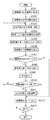
次に、図1のブロック図と、図3のフローチャートを参照して、本実施形態の断層像撮像装置10の構成、および断層像撮像装置10が実行する具体的な処理の手順を説明する。
Next, with reference to the block diagram of FIG. 1 and the flowchart of FIG. 3, the configuration of the
ステップS301において、計測範囲取得部101は、指示取得部100から被験者の眼底に対する2次元の計測範囲RXYを設定するための操作者による指示情報を取得し、計測範囲RXYを特定する。この指示情報は、断層像撮像装置10に備えられた不図示のキーボードやマウスを介して、操作者によって入力される。眼底上の計測範囲RXYの指示として、例えば、断層像取得対象の眼底上の部位や位置の指定などの指示(これを指示1と定義する)を取得する。そして、この指示1の内容に基づき矩形の計測範囲RXYを特定する。特定された計測範囲RXYは、断層像取得位置設定部102へと送信される。
In step S301, the measurement
ステップS302において、断層像取得位置設定部102は、計測範囲取得部101から計測範囲RXYを取得し、この計測範囲の中から断層像を取得する位置(以降、断層像取得位置Pと呼ぶ)を設定する。断層像取得位置Pには、診断用の撮影よりも少ない予め定められた複数の位置が設定される。本ステップでは、断層像取得位置Pとして、例えば計測範囲RXYの中央と端部の位置を設定する。もちろん、断層像取得位置Pは個の組み合わせに限られるものではない。例えば、中央部と両端部の間に一つずつ取得位置を追加し、断層像取得位置Pを5つとしても良い。
In step S302, the tomographic image acquisition
図6の(a)は、計測範囲RXYにおける断層像取得位置Pを示す図である。601は眼底像を表し、眼底像601内のRXYは2次元の計測範囲を表す。計測範囲RXY内のCは、計測範囲RXYの中心を通り図中のx軸に平行な線分(以降、中央部と呼ぶ)、Uは計測範囲RXYの上辺(以降、上端部と呼ぶ)、Lは計測範囲RXYの下辺(以降、下端部と呼ぶ)、をそれぞれ表す。本実施形態では、計測範囲RXYの中央部と両端部を示す位置として、計測範囲RXYの中央部C、上端部U、下端部Lの3つの位置を適用する。これらの位置は、図13の(a)に相当する(1302〜1304)。以降で説明する断層像取得時には、中央部C、上端部U、下端部Lの位置に対して、z軸方向に計測範囲RZの領域をスキャンした断層像を取得することになる。しかし、前述の通り、計測範囲RXYの中央と端部の位置はこれに限定されず、図13の(b)〜(f)のような位置であっても良い。こうして、設定された断層像取得位置P(中央部C、上端部U、下端部L)は、断層像取得部103へと送信される。
FIG. 6A is a diagram illustrating a tomographic image acquisition position P in the measurement range RXY .
ステップS303において、移動量設定部109は、指示取得部100から網膜の深度方向の計測位置を手動設定するための操作者による指示情報を取得する。この指示は、不図示のユーザーインターフェイスを用いて、操作者によって入力される。計測位置を設定するための指示として、ここでは、深度方向(z軸方向)への計測位置の移動量(以降、深度方向移動量Dと呼ぶ)を取得する。そして、設定した深度方向移動量Dの値は、断層像取得部103へと送信される。
In step S <b> 303, the movement
ステップS303において、断層像取得部103は断層像取得位置設定部102から取得した断層像取得位置P及び、移動量設定部109から取得した深度方向移動量Dに基づき、被験眼の断層像を撮像する。
In step S <b> 303, the tomographic
断層像取得部103は、本実施形態ではフーリエドメイン方式のOCTからなる。図2に、断層像取得部103の機能及び装置構成を示す。断層像取得部103は、断層像取得位置Pに従ってガルバノミラー駆動機構203を制御し、ガルバノミラー204を駆動する。ガルバノミラー駆動機構203は、信号光を主走査及び副走査方向(図6のx軸及びy軸方向)にスキャンするようにガルバノミラー204を駆動する。ここでは、図6の中央部C、上端部U、下端部Lの3箇所の位置を実時間で撮像するため、1回の主走査において、これらの3箇所を同時にスキャンするように制御する。具体的には、副走査方向において、スキャン位置を中央部C、上端部U、下端部Lの3箇所の間で高速に切り替えることで、副走査の位置を固定して主走査を行う場合の1/3のサンプリング間隔で主走査方向にスキャンするように制御する。また、断層像取得部103は、深度方向移動量Dに従って参照ミラー駆動機構209を制御し、参照ミラー202を駆動する。
In the present embodiment, the tomographic
そして、低コヒーレンス光源200からの光ビームは、ハーフミラー201により、対物レンズ210を経由して被測定物体211に向かう信号光と参照ミラー202に向かう参照光とに分割される。次に、被測定物体211及び参照ミラー202によりそれぞれ反射された信号光及び参照光を重畳することにより干渉光が生成される。この干渉光は回折格子205によって波長λ1〜λnの波長成分に分光され、各波長成分が1次元光センサアレイ206によって検出される。1次元光センサアレイ206を構成する各光センサは、検出した波長成分の光強度の検出信号を画像再構成部208に出力する。
Then, the light beam from the low-
画像再構成部208は、1次元光センサアレイ206から出力された干渉光の各波長成分の検出信号に基づいて、この干渉光についての波長−光強度の関係、すなわち干渉光の光強度分布(波長スペクトル)を求める。求めた干渉光の波長スペクトルをフーリエ変換し、網膜の断層像を再構成する。
Based on the detection signal of each wavelength component of the interference light output from the one-dimensional photosensor array 206, the
図6の(b)は、中央部C、上端部U、下端部Lにおいて取得された断層像を示す図である。RZは図5と同様にz軸方向における1次元の計測範囲を表す。この計測範囲RZは、制御・移動された参照ミラー202の位置に基づいて決定される、断層像の深さ方向(奥行き方向)の範囲である。TCは図6の(a)の中央部Cに対応する断層像(以降、中央部断層像と呼ぶ)、TUは図6の(a)の上端部Uに対応する断層像(以降、上端部断層像と呼ぶ)、TLは図6の(a)の下端部Lに対応する断層像(以降、下端部断層像と呼ぶ)、を表す。撮像された断層像の画像データは、記憶部104へと送信される。
FIG. 6B is a diagram illustrating a tomographic image acquired at the center C, the upper end U, and the lower end L. R Z represents a one-dimensional measurement range in the z-axis direction as in FIG. The measurement range RZ is a range in the depth direction (depth direction) of the tomographic image determined based on the position of the controlled and moved
次に、ステップS305において、表示方法設定部105は、記憶部104に記憶された断層像の画像データを取得し、断層像の画像データを並べて同時に表示する表示方法に設定する(これを表示方法1と定義する)。
Next, in step S305, the display
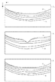
図7は、表示方法1の一例を表している。TUは、上端部断層像、TCは中央部断層像、TLは下端部断層像を表す。また、図5と同様に、各断層像内のAは内境界膜、Bは網膜色素上皮層境界を表す。図7に示すように本実施形態では、上から順に上端部断層像TU、中央部断層像TC、下端部断層像TLを並べて表示する方法を適用している。しかし、断層像の表示方法は、各断層像が並んだ状態で同時に確認できるのであれば、この方法に限定されない。例えば、これらの断層像を横や斜めに並べて表示しても良い。また、図8は、網膜層に途切れが生じている場合の表示方法1の一例を表している。図8におけるTU、TC、TL、A、Bは、図7と同様にそれぞれ、上端部断層像、中央部断層像、下端部断層像、内境界膜、網膜色素上皮層境界を表す。図8では、上端部断層像TU及び下端部断層像TLにおいて、内境界膜Aが上辺から途切れている。断層像の並べ方は図7と同様である。 FIG. 7 shows an example of the display method 1. T U is the upper end portion tomographic image, T C is the central portion tomographic image, T L represents the lower end tomogram. Similarly to FIG. 5, A in each tomogram represents the inner boundary membrane, and B represents the retinal pigment epithelial layer boundary. As shown in FIG. 7, in the present embodiment, a method of displaying the upper-end tomographic image T U , the central tomographic image T C , and the lower-end tomographic image TL in order from the top is applied. However, the display method of the tomographic image is not limited to this method as long as the tomographic images can be simultaneously confirmed in a state where the tomographic images are arranged. For example, these tomographic images may be displayed side by side or diagonally. FIG. 8 shows an example of the display method 1 when the retinal layer is interrupted. 8, T U , T C , T L , A, and B represent the upper end tomographic image, the central tomographic image, the lower end tomographic image, the inner boundary membrane, and the retinal pigment epithelium layer boundary, respectively. . 8, at the upper end tomographic image T U and the lower end portion tomographic image T L, the inner limiting membrane A is interrupted from the top. The arrangement of the tomographic images is the same as in FIG.
このように、中央と端部の断層像を並べて表示させることにより、ユーザは断層像から網膜層が途切れているかどうかを確認することができ、撮像後の3次元データから網膜層に途切れが生じるかどうかを判断することができる。そして、設定された表示方法1のデータ及び表示する断層像の画像データは、表示部106に送信される。
In this way, by displaying the tomographic images at the center and the edge side by side, the user can check whether the retinal layer is interrupted from the tomographic image, and the retinal layer is interrupted from the three-dimensional data after imaging. You can judge whether or not. Then, the set display method 1 data and tomographic image data to be displayed are transmitted to the
次の、ステップS306からS308の処理は、断層像における網膜層の途切れを検出し、途切れが検出された断層像の表示形態を他の断層像と異ならせることにより、警告を行う処理である。まず、ステップS306において、網膜層抽出部107は、記憶部104に記憶された断層像の画像データを取得し、断層像のそれぞれから画像解析により網膜層を抽出する。
The next processing in steps S306 to S308 is processing for warning by detecting a discontinuity of the retinal layer in the tomographic image and making the display form of the tomographic image in which the discontinuity is detected different from other tomographic images. First, in step S306, the retinal
本ステップでは、網膜層として、図7の内境界膜A及び網膜色素上皮層境界Bの2つの層を抽出する。内境界膜Aは、画像上で低輝度の領域として描出されるその上側の硝子体領域と、高輝度の領域として描出されるその下側の神経線維層に挟まれた境界であるため、画像上の輝度勾配が大きくなる性質がある。そこで本実施形態では、1つのA−スキャンラインに関して、画像上端からz軸正方向に注目画素を順に走査し、注目画素近傍の画像勾配が一定閾値TAを超えた位置で走査を停止することで、停止位置の画素を、内境界膜の画素として抽出する。これを全てのA−スキャンラインに対して繰り返すことで、断層像から内境界膜の抽出を行う。 In this step, two layers of the inner boundary membrane A and the retinal pigment epithelium layer boundary B in FIG. Since the inner boundary film A is a boundary sandwiched between the vitreous region above it depicted as a low luminance region on the image and the nerve fiber layer below it depicted as a high luminance region, There is a property in which the upper brightness gradient is increased. Therefore, in this embodiment, for one A- scan lines, the pixel of interest from the image upper end in the z-axis positive direction is sequentially scanned, the image gradients around the target pixel stops scanning at the position beyond the predetermined threshold value T A Thus, the pixel at the stop position is extracted as a pixel of the inner boundary film. By repeating this for all A-scan lines, the inner boundary film is extracted from the tomographic image.
また、網膜色素上皮層境界Bとその一つ上側の境界である視細胞内節外節接合部(IS/OS)との間に挟まれた領域(網膜色素上皮層)は、網膜層の中でも特に高輝度の領域として描出される。それに比べてIS/OSの上側の領域は比較的低輝度であるため、IS/OSにおける画像上の輝度勾配が大きくなる性質がある。そこで本実施形態では、1つのA−スキャンラインに関して、抽出された内境界膜Aの位置を基点にz軸正方向に注目画素を走査し、注目画素近傍の画像勾配が一定閾値TIを超えた位置で走査を停止することで、停止位置の画素をIS/OSの画素として抽出する。これを全てのA−スキャンラインに対して繰り返すことで、断層像からIS/OSの層が抽出される。 In addition, the region (retinal pigment epithelium layer) sandwiched between the retinal pigment epithelium layer boundary B and the one-upper boundary of the photoreceptor inner / outer segment joint (IS / OS) is also a part of the retinal layer. It is depicted as a particularly bright area. On the other hand, since the upper area of IS / OS has a relatively low luminance, the luminance gradient on the image in IS / OS has a property of increasing. Therefore, in this embodiment, for one A- scan lines, the position of the boundary layer A among extracted by scanning the target pixel in the positive direction of the z-axis as a base point, the image gradients around the target pixel is greater than a predetermined threshold value T I By stopping scanning at the position, the pixel at the stop position is extracted as an IS / OS pixel. By repeating this operation for all A-scan lines, an IS / OS layer is extracted from the tomographic image.
そして、1つのA−スキャンラインに関して、IS/OSを基点としてz軸正方向にさらに注目画素を走査し、輝度値が一定閾値TBよりも低くなる位置で走査を停止することで、停止位置の画素を網膜色素上皮層境界Bの画素として抽出する。これを全てのA−スキャンラインに対して繰り返すことで網膜色素上皮層境界Bの層が抽出される。そして、断層像の画像データ及び抽出された網膜層データ(内境界膜、IS/OS、網膜色素上皮層境界の3つの境界データ)は、網膜層途切れ検出部108に送信される。
Then, for one A- scan lines, by scanning the further the pixel of interest in the positive direction of the z-axis the IS / OS as a base point, the luminance value stops scanning at lower position than the predetermined threshold value T B, the stop position Are extracted as pixels of the retinal pigment epithelium layer boundary B. By repeating this operation for all A-scan lines, the layer of the retinal pigment epithelium layer boundary B is extracted. The tomographic image data and the extracted retinal layer data (the three boundary data of the inner boundary membrane, IS / OS, and retinal pigment epithelium layer boundary) are transmitted to the retinal layer
ステップS307において、網膜層途切れ検出部108は、網膜層抽出部107から取得した断層像の画像データ及び網膜層データに基づき網膜層の途切れを検出し、網膜層の途切れを検出した網膜層データを生成する。このデータを網膜層途切れ検出データと定義する。途切れ、すなわち網膜層が深さ方向の計測範囲からはみ出していることが検出された場合は、網膜層が途切れていることを表すフラグをTrueに設定し、検出されなかった場合は、Falseに設定する。このフラグを、途切れ検出フラグEと定義する。そして、途切れ検出フラグE=Trueのときは、途切れ検出フラグEの値と網膜層途切れ検出データを、記憶部104に送信しステップS308に移る。途切れ検出フラグE=Falseのときは、途切れ検出フラグEの値のみを記憶部104に送信しステップS312に移る。
In step S307, the retinal layer
本ステップでは、網膜層の途切れを以下の方法で検出する。まず、図8の断層像上における内境界膜Aの途切れの検出方法を説明する。1つのA−スキャンラインにおける、ステップS306で検出された内境界膜A上の点をpAとする。このとき、点pAに対して上側(z軸負の方向)の一定領域(例えば3画素程度)を参照領域Xと定義する。そして、参照領域Xの輝度値が本来内境界膜Aの上側に存在する硝子体領域の輝度値から一定範囲に収まる場合は途切れていない、収まらない場合は途切れていると判定する。この条件式を下記の式で表す。
![]()
![]()
式(1)において、VXは参照領域Xの平均輝度値、VCorpusは硝子体領域の平均輝度値、TAは一定の輝度値の幅を示す正の定数である。このように、式(1)を満たさない場合は、点pAとして硝子体領域と隣接しない別の点が検出されているため、A−スキャンライン上に内境界膜Aが写っておらず断層像上辺から途切れているとみなせる。また、点pAの上側に画素が存在しない場合は、点pAは断層像の上辺に位置するので、途切れていると判定する。 In the formula (1), the average luminance value of V X is the reference area X, V Corpus the average luminance value of the vitreous region is T A is a positive constant that indicates the width of constant luminance value. As described above, when Expression (1) is not satisfied, another point that is not adjacent to the vitreous region is detected as the point p A. Therefore, the inner boundary film A is not reflected on the A-scan line and the fault is detected. It can be regarded as being interrupted from the top of the image. Also, if the pixel on the upper side of the point p A is not present, since the point p A located upper side of the tomographic image is determined to be interrupted.
次に、網膜色素上皮層境界Bの途切れの検出方法を説明する。1つのA−スキャンラインにおける、ステップS306で検出された網膜色素上皮層境界B上の点をpB、IS/OS上の点をpIとする。このとき、点pIとpBに挟まれた領域を参照領域Yと定義する。そして、参照領域Yの輝度値が本来IS/OSと網膜色素上皮層境界に挟まれた網膜色素上皮層の領域の輝度値から一定範囲に収まる場合は途切れていない、収まらない場合は途切れていると判定する。この条件式を下記の式で表す。
![]()
![]()
式(2)において、VYは参照領域Yの平均輝度値、VRPEは網膜色素上皮層の平均輝度値、TBは一定の輝度値の幅を示す正の定数である。このように、式(2)を満たさない場合は、点pB、pIとして網膜色素上皮層の領域と隣接しない別の点が検出されているため、A−スキャンライン上に網膜色素上皮層が写っておらず断層像下辺から途切れているとみなせる。また、式(2)を満たしていたとしても、点pBの下側に画素が存在しない場合は、点pBは断層像の下辺に位置するので、途切れていると判定する。 In the formula (2), the average luminance value of V Y reference region Y, V RPE is an average luminance value of the retinal pigment epithelium, T B are positive constants indicating the width of constant luminance value. In this way, when the expression (2) is not satisfied, since another point not adjacent to the region of the retinal pigment epithelium layer is detected as the points p B and p I , the retinal pigment epithelium layer on the A-scan line. Is not reflected and can be regarded as broken from the bottom of the tomographic image. Further, even when not satisfy the equation (2), if the pixels do not exist on the lower side of the point p B, since the point p B is located lower side of the tomographic image is determined to be interrupted.
以上のようにしてA−スキャンラインごとに途切れているかどうかが判定された網膜層データ(内境界膜Aまたは網膜色素上皮層境界B)と断層像の画像データを合わせたデータを、網膜層途切れ検出データとする。 As described above, retinal layer data obtained by combining retinal layer data (inner boundary membrane A or retinal pigment epithelial layer boundary B) determined to be interrupted for each A-scan line and tomographic image data is obtained. Detected data.
次に、ステップS308において、表示方法設定部105は、記憶部104から途切れ検出フラグE=Trueのデータ及び網膜層途切れ検出データを取得し、表示方法を警告表示する方法(これを表示方法2と定義する)に設定する。以下で説明するように、表示方法2では、網膜層が深さ方向にはみ出していることが検出された断層像の表示形態を、他の断層像の表示形態(網膜層がはみ出していない断層像の表示形態)と異ならせる。
Next, in step S308, the display
図9は表示方法2の一例として内境界膜が途切れた場合の警告表示を示す図である。この表示方法は、網膜層途切れ検出データが内境界膜のデータである場合に適用される。図9の表示方法2は、図8の表示方法1の各部分が警告表示用に変更されたものに相当する。図9において、TUは、上端部断層像、TCは中央部断層像、TLは下端部断層像を表す。901は、内境界膜が途切れていることを文章で伝える警告表示、902は途切れが生じている内境界膜の端点の位置を示す矢印を表す。また、各断層像内のAは途切れが生じている内境界膜が太く強調表示されたものを表す。図9では、TUとTLのように内境界膜に途切れが生じている断層像は拡大表示、TCのように途切れが生じていない断層像は縮小表示されている。
FIG. 9 is a diagram showing a warning display when the inner boundary film is interrupted as an example of the display method 2. This display method is applied when the retinal layer break detection data is data of the inner boundary membrane. The display method 2 in FIG. 9 corresponds to a method in which each part of the display method 1 in FIG. 8 is changed for warning display. In Figure 9, T U is the upper end portion tomographic image, T C is the central portion tomographic image, T L represents the lower end tomogram.
また、図10は、表示方法2の一例として網膜色素上皮層境界が途切れた場合の警告表示を示す図である。この表示方法は、網膜層途切れ検出データが網膜色素上皮層境界のデータである場合に適用される。図10において、TUは上端部断層像、TCは中央部断層像、TLは下端部断層像を表す。1001は、網膜色素上皮層境界が途切れていることを文章で伝える警告表示、1002は途切れが生じている網膜色素上皮層境界の端点の位置を示す矢印を表す。また、各断層像内のBは途切れが生じている網膜色素上皮層境界が太く強調表示されたものを表す。図10では、TUとTLのように網膜色素上皮層境界に途切れが生じている断層像は拡大表示、TCのように途切れが生じていない断層像は縮小表示されている。
FIG. 10 is a diagram showing a warning display when the boundary of the retinal pigment epithelium layer is interrupted as an example of the display method 2. This display method is applied when the retinal layer break detection data is retinal pigment epithelium layer boundary data. In FIG. 10, T U is the upper end portion tomographic image, T C is the central portion tomographic image, T L represents the lower end tomogram.
このように、網膜層が途切れていることを、文章表示や途切れている箇所の表示、層の強調表示、断層像の拡大表示により示すことで、観察者が網膜層の途切れを認識する支援を行うことができる。そして、表示方法2のデータは表示部106に送信される。そして、ステップS309において、表示部106は、表示方法設定部105から表示方法2のデータを取得し、不図示のモニタ上に表示するよう表示制御する。
In this way, the fact that the retinal layer is interrupted is indicated by the text display, the display of the interrupted part, the layer highlighting display, and the enlarged display of the tomographic image, thereby assisting the observer to recognize the disconnection of the retinal layer. It can be carried out. Then, the data of the display method 2 is transmitted to the
次に、ステップS310において、移動量設定部109は、途切れ検出フラグE=Trueの場合に、指示取得部100から計測深度の自動調整を指示するための操作者による入力が取得されたか否かを判定する。この指示は、不図示のユーザーインターフェイスを用いて、操作者によって入力される。このとき、移動量設定部109が自動調整を指示する入力が取得された場合には、ステップS311へと移る。取得されなかった場合には、ステップS303へと移る。
Next, in step S310, the movement
ステップS311において、移動量設定部109は、ステップS310で取得した網膜層途切れ検出データに基づき、網膜に対して奥行き方向の計測深度を自動調整するための移動量を設定する。次に、設定した移動量に基づき、断層像取得部103は断層像の画像データを取得する。その次に、表示方法設定部105は、取得した断層像の表示方法を、表示方法1に設定する。そして、設定した表示方法1のデータは記憶部104に送信される。本ステップの処理の詳細については、図4に示すフローチャートを用いて後に詳しく説明する。
In step S311, the movement
ステップS312において、表示部106は、表示方法設定部105から表示方法1のデータを取得し、不図示のモニタ上に表示するよう表示制御する。そして、ステップS313において、指示取得部100は、断層像撮像装置10による断層像の解析・表示処理を終了するか否かの指示を外部から取得する。この指示は、不図示のユーザーインターフェイスを用いて、操作者によって入力される。処理を終了せずに、眼底像上の注目箇所の指定を行った場合、処理はステップS301に戻る。処理を終了する指示を取得した場合には、断層像撮像装置10はその処理を終了する。
In step S <b> 312, the
次に、図4を参照して、ステップS311の計測深度の自動調整処理を説明する。
ステップS401において、移動量設定部109は、網膜層途切れ検出部108から網膜層途切れ検出データを取得して解析し、必要な移動量を設定する(これを深度方向移動量D’と定義する)。断層像の撮影時において、参照ミラー202が深度方向移動量Dだけ移動することにより、計測範囲RZの断層像が得られる。そして、深度方向移動量D’が設定されると、断層像の撮影時において参照ミラー202の深度方向移動量Dの移動開始位置がD’だけシフトされ、計測範囲RZがD’だけシフトする。本ステップでは、網膜層途切れ検出データが内境界膜の途切れを示すデータである場合は、網膜層の上側が途切れているため、z軸の負の方向に計測範囲RZを移動させる(深度方向移動量D’は負の値になる)。逆に、網膜層途切れ検出データが網膜色素上皮層境界のデータである場合は、下側の網膜層が途切れているため、z軸正の方向に計測範囲RZを移動させる(深度方向移動量D’は正の値になる)。
Next, the automatic adjustment processing of the measurement depth in step S311 will be described with reference to FIG.
In step S401, the movement
まず、内境界膜が途切れた場合(深度方向移動量D’が負の値の場合)の深度方向移動量D’の設定方法を説明する。本実施形態では、正の定数をdCとして、深度方向移動量D’=−dCと設定しても良いし、網膜層が途切れなくなるために必要な距離dX(正の値)を計算して、深度方向移動量D’=−dXと設定しても良い。dXの設定方法を以下で説明する。 First, a method for setting the depth direction movement amount D ′ when the inner boundary film is interrupted (when the depth direction movement amount D ′ is a negative value) will be described. In the present embodiment, the positive constant may be set as d C , and the depth direction movement amount D ′ = − d C may be set, or the distance d X (positive value) necessary for the retinal layer not to be interrupted is calculated. to the depth direction movement amount D '= - may be set as d X. how to set d X described below.
図11の(a)は、途切れた内境界膜の推定ラインと断層像との位置関係を示す図である。1101は、端部の断層像(上端部断層像または下端部断層像)であり、Aは内境界膜を表す。また、A’は内境界膜Aの輪郭を外挿することにより推定された、途切れた内境界膜の推定ラインを表す。さらに、d1は推定ラインA’と断層像の上辺の左端との距離、d2は推定ラインA’と断層像の上辺の右端との距離を表す。
(A) of FIG. 11 is a figure which shows the positional relationship of the estimated line of a broken inner boundary film, and a tomogram.
推定ラインA’の推定方法として、網膜の3次元形状が楕円体に近似できることを利用して、例えば検出された内境界膜Aに対して楕円形状をフィッティングして得られる曲線を推定ラインA’として適用する方法を用いる。その他、網膜の形状を考慮した推定方法であれば、この方法に限定しない。 As an estimation method of the estimated line A ′, for example, a curve obtained by fitting the elliptical shape to the detected inner boundary film A is estimated by using the fact that the three-dimensional shape of the retina can be approximated to an ellipsoid. The method applied is used. Any other estimation method that takes into account the shape of the retina is not limited to this method.
そして、距離dXとして、距離d1と距離d2のうち値が大きいものを採用する。図11の(a)の例ではd1>d2が成り立つので、dX=d1となる。これにより、断層像の上辺から最も離れている推定ラインA’上の位置からの、断層像の上辺までの距離を、距離dXとして設定できる。従って、z軸負の方向に距離dXだけ計測範囲RZを移動させることで、断層像に内境界膜Aを収めることができる。 Then, the distance d X having a larger value among the distance d 1 and the distance d 2 is employed. In the example of FIG. 11A, d 1 > d 2 holds, so d X = d 1 . Thus, from the position on the farthest are estimated line A 'from the upper side of the tomographic image, the distance to the upper side of the tomographic image can be set as a distance d X. Therefore, by moving the measurement range R Z in the direction of the z-axis negative distance d X, it is possible to keep the inner limiting membrane A tomographic image.
次に、網膜色素上皮層境界が途切れた場合の深度方向移動量D’の設定方法を説明する。この場合は、内境界膜が途切れた場合と符号を逆にして、D’=dCとしても良いし、D’=dXとしても良い。dXの設定方法を以下で説明する。 Next, a method of setting the depth direction movement amount D ′ when the retinal pigment epithelium layer boundary is interrupted will be described. In this case, the sign may be reversed from that in the case where the inner boundary film is interrupted, and D ′ = d C or D ′ = d X. how to set d X described below.
図11の(b)は、途切れた網膜色素上皮層境界の推定ラインと断層像との位置関係を示す図である。1102は、端部の断層像(上端部断層像または下端部断層像)であり、Bは網膜色素上皮層境界を表す。また、B’は途切れた網膜色素上皮層境界の輪郭を外装して得られた推定ラインを表し、d3は、推定ラインB’の最もz座標が大きい位置と断層像の下辺との距離を表す。網膜色素上皮層境界も網膜の一部であるので、推定ラインB’も推定ラインA’と同様の方法で求める。そして、距離dX=d3と設定することで、z軸正の方向にdXだけ計測範囲RZを移動させ、断層像に網膜色素上皮層境界Bを収めることができる。こうして、設定した深度方向移動量D’の値は断層像取得部103へと送信される。
FIG. 11B is a diagram showing the positional relationship between the estimated line of the discontinuous retinal pigment epithelium layer and the tomographic image.
ステップS402において、断層像取得部103は、移動量設定部109から取得した深度方向移動量D’及びステップS302で断層像取得位置設定部102により設定された断層像取得位置Pに基づき、被験眼の断層像を撮像する。処理の詳細はステップS303と同様であるため、省略する。撮像された断層像の画像データは、記憶部104へと送信される。
In step S402, the tomographic
ステップS403において、網膜層抽出部107は、記憶部104に記憶された断層像の画像データを取得し、画像解析により網膜層を抽出する。処理の詳細はステップS306と同様であるため、省略する。断層像の画像データ及び抽出された網膜層のデータは、網膜層途切れ検出部108に送信される。そして、ステップS404において、網膜層途切れ検出部108は、網膜層抽出部107から取得した断層像の画像データ及び抽出された網膜層のデータに基づき網膜層の途切れを検出する。処理の詳細はステップS307と同様であるため、省略する。途切れ検出フラグE=Trueのときは、途切れ検出フラグEの値と網膜層途切れ検出データを、記憶部104に送信しステップS401に移る。途切れ検出フラグE=Falseのときは、途切れ検出フラグEの値のみを記憶部104に送信しステップS405に移る。
In step S403, the retinal
ステップS405において、表示方法設定部105は、記憶部104に記憶された断層像の画像データと途切れ検出フラグE=Falseの値を取得し、断層像の画像データを並べて同時に表示する表示方法、すなわち表示方法1に設定する。処理の詳細はステップS304と同様であるため、省略する。設定された表示方法1のデータ及び表示する断層像の画像データは、表示部106に送信される。
In step S405, the display
以上の手順により計測深度の自動調整が行われる。但し、ステップS401において深度方向移動量D’=−dCと設定した場合は(内境界膜が途切れているとき)、ステップS402において参照ミラーを一定量だけ移動させた断層像を取得する。従って、この処理とステップS404で網膜層の途切れをチェックする、という手順を何度も繰り返し(ステップS401〜S404)、網膜の途切れが検出されなくなったときに次の処理に移るという流れになる。 The measurement depth is automatically adjusted by the above procedure. However, when the depth direction movement amount D ′ = − d C is set in step S401 (when the inner boundary film is interrupted), a tomographic image in which the reference mirror is moved by a certain amount is acquired in step S402. Therefore, this process and the procedure of checking the interruption of the retinal layer in step S404 are repeated many times (steps S401 to S404), and the process proceeds to the next process when the interruption of the retina is no longer detected.
一方、ステップS401において深度方向移動量D’=−dXと設定した場合は、ステップS402において途切れが生じなくなるために必要なだけ参照ミラーを移動させた断層像を取得する。従って、ステップS404で網膜層の途切れを一度チェックした後に、次の処理に移るという流れになる。或いは、この場合、必要なだけ参照ミラーを移動させているので、ステップS403、S404による確認処理を省略するようにしてもよい。 On the other hand, the depth direction movement amount D '= in step S401 - If set to d X, acquires the tomographic image interrupted moves the reference mirror as necessary to not occur at step S402. Therefore, after checking the retinal layer break once in step S404, the process proceeds to the next process. Alternatively, in this case, since the reference mirror is moved as much as necessary, the confirmation processing in steps S403 and S404 may be omitted.
以上、述べた構成によれば、網膜の3次元形状は楕円体に近似できるため、被験眼の計測範囲RXYにおける中央と端部の断層像を実時間で参照可能にすることで、撮像後に得られる3次元データ全体に網膜層が収まるかどうかを被験眼観察時に判断可能になる。そして、網膜層の途切れが検出された場合に警告提示することで、撮影者が網膜層の途切れを認識する支援を行うことができる。さらに、網膜層の途切れが検出された場合に、撮影者の指示により網膜層の途切れの状態を解析し、網膜層が断層像から途切れないように網膜の奥行き方向の計測深度を自動調整することで、撮影者が位置を調整する負担を軽減しかつ撮影ミスを防ぐことができる。 According to the configuration described above, since the three-dimensional shape of the retina can be approximated to an ellipsoid, the tomograms at the center and the end in the measurement range RXY of the subject eye can be referred to in real time. Whether or not the retinal layer fits in the entire three-dimensional data obtained can be determined during observation of the subject's eye. Then, when the retinal layer break is detected, a warning is presented so that the photographer can assist in recognizing the retinal layer break. Furthermore, when a break in the retinal layer is detected, the state of the retinal layer break is analyzed according to the photographer's instruction, and the measurement depth in the depth direction of the retina is automatically adjusted so that the retinal layer does not break from the tomographic image. Thus, it is possible to reduce the burden of the photographer adjusting the position and to prevent a photographing error.
一方、網膜層の途切れが検出された場合に、撮影者が自動調整の指示を与えないときは計測深度の手動入力を取得できるようにする。このように構成することで、撮影者は網膜層の途切れを示す警告表示を参照しながら、手動で計測深度の位置合わせ(参照ミラー202の位置合わせ)を行うことができる。このとき、参照ミラー202の位置合わせを行った結果はリアルタイムに表示方法2で表示され、網膜層の途切れが解消すると表示方法1による表示が実行される。
On the other hand, when a break in the retinal layer is detected, a manual input of the measurement depth can be acquired when the photographer does not give an instruction for automatic adjustment. With this configuration, the photographer can manually align the measurement depth (alignment of the reference mirror 202) while referring to a warning display indicating a break in the retinal layer. At this time, the result of the alignment of the
また、図1において、網膜層抽出部107及び網膜層途切れ検出部108、表示方法設定部105における表示方法2を省くことで、表示方法1のみが表示方法設定部105で適用され、表示部106によって実時間で表示される構成にすることもできる。この場合、網膜層の途切れの検出が行われないため、移動量設定部109には撮影者からの手動による計測深度の指示のみが入力される。従って、撮影者は計測範囲RXYの中央部と両端部の位置におけるそのままの断層像を実時間で参照しながら、手動で計測深度の位置合わせを行うことができる。この場合、図3のS303〜S305が繰り返し実行されることになる。
Further, in FIG. 1, by omitting the display method 2 in the retinal
その他、自動調整を行う場合には、ユーザは断層像をチェックする必要がない。よって、表示方法設定部105での表示方法を中央部の断層像1枚のみの表示にするようにしてもよい。このように、両端部の断層像表示及び網膜層途切れの警告表示を行わずに、網膜層が途切れた場合に移動量設定部109が計測深度を自動調整する構成にすることもできる。この場合、撮影者には両端部の断層像の状態が提示されないので、撮影者は端部の断層像の状態を意識することなく、コンピュータが自動調整した位置に基づいて撮影ミスのない3次元データを取得することができる。この構成では、網膜に途切れが生じた場合に、断層像の提示以外の何らかの通知手段(音声通知など)を用いて途切れの発生を撮影者に通知した後に撮影者からの指示を取得して自動調整しても良いし、通知せずに自動調整しても良い。
In addition, when performing automatic adjustment, the user does not need to check a tomogram. Therefore, the display method in the display
(その他の実施形態)
前記それぞれの実施形態は、本発明を撮像装置として実現したものである。しかしながら、本発明の実施形態は撮像装置のみに限定されるものではない。本実施形態では、本発明をコンピュータ上で動作するソフトウェアとして実現する構成を説明する。図12は、断層像撮像装置10の各部の機能をソフトウェアで実現するためのコンピュータの基本構成を示す図である。
(Other embodiments)
In each of the above embodiments, the present invention is realized as an imaging apparatus. However, the embodiment of the present invention is not limited only to the imaging apparatus. In the present embodiment, a configuration for realizing the present invention as software that operates on a computer will be described. FIG. 12 is a diagram illustrating a basic configuration of a computer for realizing the functions of the respective units of the
CPU1201は、RAM1202やROM1203に格納されたコンピュータプログラムやデータを用いてコンピュータ全体の制御を行う。また、断層像撮像装置10の各部に対応するソフトウェアの実行を制御して、各部の機能を実現する。RAM1202は、外部記憶装置1204からロードされたコンピュータプログラムやデータを一時的に記憶するエリアを備えると共に、CPU1201が各種の処理を行うために必要とするワークエリアを備える。記憶部104の機能はRAM1202によって実現される。ROM1203は、一般にコンピュータのBIOSや設定データなどが格納されている。外部記憶装置1204は、ハードディスクドライブなどの大容量情報記憶装置として機能する装置であって、ここにオペレーティングシステムやCPU1201が実行するコンピュータプログラム等を保存する。また本実施形態の説明において既知としている情報はここに保存されており、必要に応じてRAM1202にロードされる。モニタ1205は、液晶ディスプレイなどにより構成されている。例えば、表示部106が出力する内容を表示することができる。キーボード1206、マウス1207は入力デバイスであり、操作者はこれらを用いて、各種の指示を断層像撮像装置10に与えることができる。インターフェイス1208は、断層像取得部103との間でデータのやり取りを行うためのインらーフェイスである。なお、外部の機器との間で各種データのやりとりを行うための、IEEE1394やUSB、イーサネット(登録商標)ポート等によって構成されるインターフェイスを備えてもよい。インターフェイス1208を介して取得したデータは、RAM1202に取り込まれる。上述した各構成要素は、バス1209によって相互に接続される。
The
なお、本実施形態における断層像撮像装置10の各部の機能は、各部の機能を実現するコンピュータプログラムをCPU1201が実行し、コンピュータ全体を制御することで実現される。また、上記実施形態では、同フローチャートに従ったプログラムコードは、例えば外部記憶装置1204からRAM1202に既にロードされているものとする。
In addition, the function of each part of the
以上説明したように、上記実施形態によれば、被験眼の計測範囲における中央と端部の位置の断層像を実時間で並べて表示されるため、その後撮像する3次元データに網膜層が収まるかどうかを被験眼観察時に判別可能になる。或いは、断層像において深さ方向の撮影範囲から網膜層がはみ出さないように自動的に深度方向の撮影範囲が調整される。そのため、3次元データ撮像後の断層像において網膜層が途切れてしまうという撮影ミスを防ぐことができる。
(その他の実施形態)
また、本発明は、以下の処理を実行することによっても実現される。即ち、上述した実施形態の機能を実現するソフトウェア(プログラム)を、ネットワーク又は各種記憶媒体を介してシステム或いは装置に供給し、そのシステム或いは装置のコンピュータ(またはCPUやMPU等)がプログラムを読み出して実行する処理である。
As described above, according to the above embodiment, since the tomographic images at the center and end positions in the measurement range of the subject eye are displayed side by side in real time, is the retinal layer fit in the three-dimensional data to be imaged thereafter? Whether or not can be determined at the time of observation of the test eye. Alternatively, the imaging range in the depth direction is automatically adjusted so that the retinal layer does not protrude from the imaging range in the depth direction in the tomographic image. Therefore, it is possible to prevent an imaging error that the retinal layer is interrupted in the tomographic image after the three-dimensional data imaging.
(Other embodiments)
The present invention can also be realized by executing the following processing. That is, software (program) that realizes the functions of the above-described embodiments is supplied to a system or apparatus via a network or various storage media, and a computer (or CPU, MPU, or the like) of the system or apparatus reads the program. It is a process to be executed.
なお、上述した本実施の形態における記述は、本発明に係る好適な画像処理装置の一例であり、本発明はこれに限定されるものではない。 Note that the description in this embodiment described above is an example of a suitable image processing apparatus according to the present invention, and the present invention is not limited to this.
Claims (9)
設定手段が、眼底における、断層像を撮影すべき計測範囲を設定する設定工程と、
取得手段が、前記光干渉断層計を用いて、前記計測範囲の、診断用の撮影よりも少ない予め定められた複数の位置で断層像を取得する取得工程と、
表示制御手段が、前記取得工程で取得された断層像を、リアルタイムに、表示装置の画面に並べて表示させる表示制御工程とを有することを特徴とする断層像撮像装置の制御方法。 A method for controlling a tomographic imaging apparatus that takes a tomographic image of the fundus using an optical coherence tomography,
A setting step in which the setting means sets a measurement range in which tomographic images are to be taken on the fundus;
An acquisition step for acquiring tomographic images at a plurality of predetermined positions less than diagnostic imaging in the measurement range using the optical coherence tomography;
And a display control step for displaying the tomographic images acquired in the acquisition step side by side on the screen of the display device in real time.
検出手段が、前記断層像のそれぞれについて、前記抽出工程で抽出された網膜層が断層像の深さ方向に関して撮影範囲からはみ出しているかどうかを検出する検出工程とを更に有し、
前記表示制御工程では、前記網膜層がはみ出していることが検出された断層像の表示形態と他の断層像の表示形態とを異ならせることを特徴とする請求項1に記載の断層像撮像装置の制御方法。 An extraction unit that extracts a retinal layer from each of the tomographic images acquired in the acquisition step;
A detecting step for detecting whether or not the retinal layer extracted in the extraction step protrudes from the imaging range in the depth direction of the tomographic image for each of the tomographic images;
2. The tomographic imaging apparatus according to claim 1, wherein in the display control step, a display form of a tomographic image in which it is detected that the retinal layer protrudes is different from a display form of another tomographic image. Control method.
設定手段が、眼底における、断層像を撮影すべき計測範囲を設定する設定工程と、
取得手段が、前記光干渉断層計を用いて、前記計測範囲の、診断用の撮影よりも少ない予め定められた複数の位置で断層像を取得する取得工程と、
抽出手段が、前記取得工程で取得した断層像の各々から網膜層を抽出する抽出工程と、
調整手段が、前記抽出工程で抽出された網膜層の断層像における深さ方向の位置に基づいて、網膜層が深さ方向に撮影範囲をはみ出さないように前記光干渉断層計の参照ミラーの位置を調整する調整工程とを有することを特徴とする断層像撮像装置の制御方法。 A method for controlling a tomographic imaging apparatus that takes a tomographic image of the fundus using an optical coherence tomography,
A setting step in which the setting means sets a measurement range in which tomographic images are to be taken on the fundus;
An acquisition step for acquiring tomographic images at a plurality of predetermined positions less than diagnostic imaging in the measurement range using the optical coherence tomography;
An extracting step for extracting a retinal layer from each of the tomographic images acquired in the acquiring step;
Based on the position in the depth direction in the tomographic image of the retinal layer extracted in the extraction step, the adjusting means adjusts the reference mirror of the optical coherence tomometer so that the retinal layer does not protrude from the imaging range in the depth direction. A control method for the tomographic imaging apparatus, comprising: an adjusting step for adjusting a position.
各断層像について前記抽出された網膜層が深さ方向に撮影範囲をはみ出しているか否かを判断し、
はみ出していると判断された場合に、網膜層の輪郭を外挿することによりそのはみ出しの量を推定し、
推定されたはみ出しの量に基づいて前記参照ミラーの位置を調整することを特徴とする請求項3に記載の断層像撮像装置の制御方法。 In the adjustment step,
For each tomographic image, determine whether the extracted retinal layer protrudes from the imaging range in the depth direction,
If it is determined that it is protruding, extrapolate the outline of the retinal layer to estimate the amount of protrusion,
4. The method for controlling a tomographic imaging apparatus according to claim 3, wherein the position of the reference mirror is adjusted based on the estimated amount of protrusion.
眼底における、断層像を撮影すべき計測範囲を設定する設定手段と、
前記光干渉断層計を用いて、前記計測範囲の、診断用の撮影よりも少ない予め定められた複数の位置で断層像を取得する取得手段と、
前記取得手段により取得された断層像を、リアルタイムに、表示装置の画面に並べて表示させる表示制御手段とを備えることを特徴とする断層像撮像装置。 A tomographic imaging apparatus for taking a tomographic image of the fundus using an optical coherence tomography,
Setting means for setting a measurement range in which tomographic images should be taken on the fundus;
Using the optical coherence tomography, acquisition means for acquiring tomographic images at a plurality of predetermined positions in the measurement range that are smaller than diagnostic imaging;
A tomographic imaging apparatus comprising: display control means for displaying the tomographic images acquired by the acquiring means side by side on the screen of the display device in real time.
眼底における、断層像を撮影すべき計測範囲を設定する設定手段と、
前記光干渉断層計を用いて、前記計測範囲の、診断用の撮影よりも少ない予め定められた複数の位置で断層像を取得する取得手段と、
前記取得手段により取得された断層像の各々から網膜層を抽出する抽出手段と、
前記抽出手段により抽出された網膜層の断層像における深さ方向の位置に基づいて、網膜層が深さ方向に撮影範囲をはみ出さないように前記光干渉断層計の参照ミラーの位置を調整する調整手段とを備えることを特徴とする断層像撮像装置。 A tomographic imaging apparatus for taking a tomographic image of the fundus using an optical coherence tomography,
Setting means for setting a measurement range in which tomographic images should be taken on the fundus;
Using the optical coherence tomography, acquisition means for acquiring tomographic images at a plurality of predetermined positions in the measurement range that are smaller than diagnostic imaging;
Extraction means for extracting a retinal layer from each of the tomographic images acquired by the acquisition means;
Based on the position in the depth direction in the tomographic image of the retinal layer extracted by the extraction means, the position of the reference mirror of the optical coherence tomography is adjusted so that the retinal layer does not protrude from the imaging range in the depth direction. A tomographic imaging apparatus comprising: an adjusting unit.
Priority Applications (7)
| Application Number | Priority Date | Filing Date | Title |
|---|---|---|---|
| JP2009186779A JP5017328B2 (en) | 2009-08-11 | 2009-08-11 | Tomographic imaging apparatus, control method therefor, program, and storage medium |
| DE112010003275T DE112010003275T5 (en) | 2009-08-11 | 2010-07-23 | TOMOGRAPHY DEVICE, ASSOCIATED CONTROL PROCEDURE, PROGRAM AND STORAGE MEDIUM |
| KR1020127005684A KR101484376B1 (en) | 2009-08-11 | 2010-07-23 | Tomography apparatus, control method for the same, and computer-readable storage medium |
| GB1204131.5A GB2485516A (en) | 2009-08-11 | 2010-07-23 | Tomography apparatus, control method for the same, program,and storage medium |
| PCT/JP2010/062968 WO2011018950A1 (en) | 2009-08-11 | 2010-07-23 | Tomography apparatus, control method for the same, program, and storage medium |
| US13/389,588 US20120140179A1 (en) | 2009-08-11 | 2010-07-23 | Tomography apparatus, control method for the same, program, and storage medium |
| CN201080035928.3A CN102469937B (en) | 2009-08-11 | 2010-07-23 | Tomography apparatus and control method for same |
Applications Claiming Priority (1)
| Application Number | Priority Date | Filing Date | Title |
|---|---|---|---|
| JP2009186779A JP5017328B2 (en) | 2009-08-11 | 2009-08-11 | Tomographic imaging apparatus, control method therefor, program, and storage medium |
Related Child Applications (1)
| Application Number | Title | Priority Date | Filing Date |
|---|---|---|---|
| JP2012056473A Division JP5174258B2 (en) | 2012-03-13 | 2012-03-13 | Tomographic imaging apparatus, control method therefor, and program |
Publications (3)
| Publication Number | Publication Date |
|---|---|
| JP2011036431A JP2011036431A (en) | 2011-02-24 |
| JP2011036431A5 JP2011036431A5 (en) | 2012-02-02 |
| JP5017328B2 true JP5017328B2 (en) | 2012-09-05 |
Family
ID=43586129
Family Applications (1)
| Application Number | Title | Priority Date | Filing Date |
|---|---|---|---|
| JP2009186779A Expired - Fee Related JP5017328B2 (en) | 2009-08-11 | 2009-08-11 | Tomographic imaging apparatus, control method therefor, program, and storage medium |
Country Status (7)
| Country | Link |
|---|---|
| US (1) | US20120140179A1 (en) |
| JP (1) | JP5017328B2 (en) |
| KR (1) | KR101484376B1 (en) |
| CN (1) | CN102469937B (en) |
| DE (1) | DE112010003275T5 (en) |
| GB (1) | GB2485516A (en) |
| WO (1) | WO2011018950A1 (en) |
Families Citing this family (19)
| Publication number | Priority date | Publication date | Assignee | Title |
|---|---|---|---|---|
| JP5415902B2 (en) * | 2009-10-27 | 2014-02-12 | 株式会社トプコン | Ophthalmic observation device |
| JP5953666B2 (en) * | 2011-07-27 | 2016-07-20 | 株式会社ニデック | Fundus photographing apparatus, fundus analysis method, and fundus analysis program |
| JP6226510B2 (en) | 2012-01-27 | 2017-11-08 | キヤノン株式会社 | Image processing system, processing method, and program |
| JP5932369B2 (en) * | 2012-01-27 | 2016-06-08 | キヤノン株式会社 | Image processing system, processing method, and program |
| JP2014045869A (en) | 2012-08-30 | 2014-03-17 | Canon Inc | Imaging apparatus, image processing device, and image processing method |
| JP2014155694A (en) * | 2013-01-16 | 2014-08-28 | Canon Inc | Ophthalmologic apparatus and ophthalmologic method |
| JP6108890B2 (en) * | 2013-03-15 | 2017-04-05 | キヤノン株式会社 | Image processing system, image processing method and program. |
| JP6130723B2 (en) * | 2013-05-01 | 2017-05-17 | キヤノン株式会社 | Information processing apparatus, information processing apparatus control method, and program |
| JP5602912B2 (en) * | 2013-06-06 | 2014-10-08 | キヤノン株式会社 | Ophthalmic equipment |
| JP6367530B2 (en) * | 2013-07-11 | 2018-08-01 | 株式会社トーメーコーポレーション | Tomographic imaging apparatus and tomographic image generation control method |
| EP3165151A4 (en) * | 2014-07-01 | 2018-03-28 | KOWA Co., Ltd. | Tomography device |
| JP2016041221A (en) | 2014-08-19 | 2016-03-31 | 株式会社トプコン | Ophthalmological photographing device and control method thereof |
| US9675244B1 (en) * | 2015-12-02 | 2017-06-13 | Novartis Ag | Location indicator for optical coherence tomography in ophthalmic visualization |
| JP7417524B2 (en) * | 2017-11-30 | 2024-01-18 | アルコン インコーポレイティド | Improving segmentation in optical coherence tomography imaging |
| JP7202808B2 (en) | 2018-08-10 | 2023-01-12 | 株式会社トプコン | Ophthalmic device and its control method |
| JP7202807B2 (en) * | 2018-08-10 | 2023-01-12 | 株式会社トプコン | ophthalmic equipment |
| JP7286853B2 (en) | 2018-08-10 | 2023-06-05 | 株式会社トプコン | Ophthalmic device and its control method |
| JP7343331B2 (en) * | 2019-08-08 | 2023-09-12 | 株式会社トプコン | Ophthalmological device, its control method, program, and recording medium |
| EP4257032A1 (en) * | 2022-04-04 | 2023-10-11 | Optos PLC | A method and system of detecting clipping of an oct image |
Family Cites Families (12)
| Publication number | Priority date | Publication date | Assignee | Title |
|---|---|---|---|---|
| US7301644B2 (en) * | 2004-12-02 | 2007-11-27 | University Of Miami | Enhanced optical coherence tomography for anatomical mapping |
| JP4916779B2 (en) * | 2005-09-29 | 2012-04-18 | 株式会社トプコン | Fundus observation device |
| ATE525012T1 (en) * | 2006-01-19 | 2011-10-15 | Optovue Inc | EYE EXAMINATION PROCEDURE USING OPTICAL COHERENCE TOMOGRAPHY |
| JP4822969B2 (en) * | 2006-07-27 | 2011-11-24 | 株式会社ニデック | Ophthalmic imaging equipment |
| JP5095167B2 (en) * | 2006-09-19 | 2012-12-12 | 株式会社トプコン | Fundus observation apparatus, fundus image display apparatus, and fundus observation program |
| JP5085086B2 (en) * | 2006-10-04 | 2012-11-28 | 株式会社トプコン | Fundus observation apparatus, fundus image display apparatus, and program |
| US8223143B2 (en) * | 2006-10-27 | 2012-07-17 | Carl Zeiss Meditec, Inc. | User interface for efficiently displaying relevant OCT imaging data |
| JP5007114B2 (en) * | 2006-12-22 | 2012-08-22 | 株式会社トプコン | Fundus observation apparatus, fundus image display apparatus, and program |
| JP4996918B2 (en) * | 2006-12-26 | 2012-08-08 | 株式会社トプコン | Optical image measurement device and program for controlling optical image measurement device |
| JP4996917B2 (en) * | 2006-12-26 | 2012-08-08 | 株式会社トプコン | Optical image measurement device and program for controlling optical image measurement device |
| JP5231802B2 (en) * | 2007-12-29 | 2013-07-10 | 株式会社ニデック | Ophthalmic imaging equipment |
| JP2009186779A (en) | 2008-02-06 | 2009-08-20 | Kyocera Mita Corp | Optical scanning device and image forming apparatus using the same |
-
2009
- 2009-08-11 JP JP2009186779A patent/JP5017328B2/en not_active Expired - Fee Related
-
2010
- 2010-07-23 WO PCT/JP2010/062968 patent/WO2011018950A1/en active Application Filing
- 2010-07-23 GB GB1204131.5A patent/GB2485516A/en not_active Withdrawn
- 2010-07-23 DE DE112010003275T patent/DE112010003275T5/en not_active Ceased
- 2010-07-23 KR KR1020127005684A patent/KR101484376B1/en active IP Right Grant
- 2010-07-23 CN CN201080035928.3A patent/CN102469937B/en active Active
- 2010-07-23 US US13/389,588 patent/US20120140179A1/en not_active Abandoned
Also Published As
| Publication number | Publication date |
|---|---|
| GB201204131D0 (en) | 2012-04-25 |
| US20120140179A1 (en) | 2012-06-07 |
| WO2011018950A1 (en) | 2011-02-17 |
| KR20120055594A (en) | 2012-05-31 |
| CN102469937A (en) | 2012-05-23 |
| GB2485516A (en) | 2012-05-16 |
| DE112010003275T5 (en) | 2012-12-20 |
| KR101484376B1 (en) | 2015-01-19 |
| CN102469937B (en) | 2015-03-25 |
| JP2011036431A (en) | 2011-02-24 |
Similar Documents
| Publication | Publication Date | Title |
|---|---|---|
| JP5017328B2 (en) | Tomographic imaging apparatus, control method therefor, program, and storage medium | |
| JP5058627B2 (en) | Fundus observation device | |
| CN111970957B (en) | Image processing method, computer-readable storage medium, and image processing apparatus | |
| JP5767014B2 (en) | Ophthalmic observation system and image processing method | |
| JP2008289579A (en) | Fundus observation apparatus and program for controlling the same | |
| JP7441783B2 (en) | Image processing method, program, ophthalmological device, and choroidal blood vessel image generation method | |
| JP2013066702A (en) | Image processing apparatus and image processing method | |
| US10561311B2 (en) | Ophthalmic imaging apparatus and ophthalmic information processing apparatus | |
| US9642519B2 (en) | Image processing apparatus and control method of image processing apparatus | |
| JP6723843B2 (en) | Ophthalmic equipment | |
| JP5543536B2 (en) | Tomographic imaging apparatus, tomographic imaging method and program | |
| JP5436630B2 (en) | Tomographic imaging apparatus, tomographic imaging method and program | |
| JP6892540B2 (en) | Ophthalmic equipment | |
| JP2023158161A (en) | Image processing method, program, image processing device, and ophthalmic system | |
| CN111989030B (en) | Image processing method, program, and image processing apparatus | |
| JP2022189963A (en) | Ophthalmologic apparatus | |
| JP5174258B2 (en) | Tomographic imaging apparatus, control method therefor, and program | |
| JP2020031873A (en) | Ophthalmologic apparatus, control method thereof, program, and recording medium | |
| JP2019054974A (en) | Ophthalmologic apparatus | |
| WO2022113409A1 (en) | Image processing method, image processing device, and program | |
| JP6877830B2 (en) | Ophthalmic equipment | |
| WO2015098912A1 (en) | Tomography device |
Legal Events
| Date | Code | Title | Description |
|---|---|---|---|
| A521 | Request for written amendment filed |
Free format text: JAPANESE INTERMEDIATE CODE: A523 Effective date: 20111117 |
|
| A621 | Written request for application examination |
Free format text: JAPANESE INTERMEDIATE CODE: A621 Effective date: 20111117 |
|
| A871 | Explanation of circumstances concerning accelerated examination |
Free format text: JAPANESE INTERMEDIATE CODE: A871 Effective date: 20111117 |
|
| A521 | Request for written amendment filed |
Free format text: JAPANESE INTERMEDIATE CODE: A523 Effective date: 20111208 |
|
| A975 | Report on accelerated examination |
Free format text: JAPANESE INTERMEDIATE CODE: A971005 Effective date: 20120106 |
|
| A131 | Notification of reasons for refusal |
Free format text: JAPANESE INTERMEDIATE CODE: A131 Effective date: 20120113 |
|
| A521 | Request for written amendment filed |
Free format text: JAPANESE INTERMEDIATE CODE: A523 Effective date: 20120313 |
|
| TRDD | Decision of grant or rejection written | ||
| A01 | Written decision to grant a patent or to grant a registration (utility model) |
Free format text: JAPANESE INTERMEDIATE CODE: A01 Effective date: 20120511 |
|
| A01 | Written decision to grant a patent or to grant a registration (utility model) |
Free format text: JAPANESE INTERMEDIATE CODE: A01 |
|
| A61 | First payment of annual fees (during grant procedure) |
Free format text: JAPANESE INTERMEDIATE CODE: A61 Effective date: 20120611 |
|
| FPAY | Renewal fee payment (event date is renewal date of database) |
Free format text: PAYMENT UNTIL: 20150615 Year of fee payment: 3 |
|
| R151 | Written notification of patent or utility model registration |
Ref document number: 5017328 Country of ref document: JP Free format text: JAPANESE INTERMEDIATE CODE: R151 |
|
| FPAY | Renewal fee payment (event date is renewal date of database) |
Free format text: PAYMENT UNTIL: 20150615 Year of fee payment: 3 |
|
| LAPS | Cancellation because of no payment of annual fees |