TECHNISCHES GEBIETTECHNICAL AREA
Die vorliegende Erfindung bezieht sich auf eine Tomographievorrichtung und ein zugehöriges Steuerverfahren, und insbesondere auf eine in der ophthalmischen Praxis usw. verwendete Tomographievorrichtung und ein zugehöriges Steuerverfahren.The present invention relates to a tomography apparatus and related control method, and more particularly to a tomography apparatus used in ophthalmic practice, etc., and an associated control method.
TECHNISCHER HINTERGRUNDTECHNICAL BACKGROUND
Eine Augentomographievorrichtung, die OCT (optische Kohärenztomographie) und dergleichen verwendet, hat in den vergangenen Jahren an Aufmerksamkeit gewonnen, weil sie die dreidimensionale Beobachtung der inneren Bedingung von Retinaschichten ermöglicht hat und für die genauere Diagnose von Krankheiten nützlich ist.An eye tomography apparatus using OCT (Optical Coherence Tomography) and the like has gained attention in recent years because it has enabled the three-dimensional observation of the inner condition of retinal layers and is useful for the more accurate diagnosis of diseases.
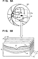
Die 5A und 5B zeigen schematische Darstellungen, die jeweils den OCT-Messbereich bei einem Fundus und entsprechenden Retinatomogrammen veranschaulichen. In 5A bezeichnet 501 ein Fundusbild und RXY bezeichnet einen zweidimensionalen OCT-Messbereich in der Fundusebene (die x-Achse stellt die horizontale Richtung und die y-Achse die vertikale Richtung dar). In dem Beispiel in 5A ist RXY ein rechteckiger Bereich. T1 bis Tn in 5B sind auch zweidimensionale Tomogramme (B-Abtast-Bilder) des Makularabschnitts, die durch die Durchführung einer Abbildung in dem Messbereich RXY in der Tiefenrichtung der Retina erhalten wurden. Jedes der Tomogramme ist aus einer Vielzahl von Abtastlinien gebildet (die nachstehend als ”A-Abtastlinien” bezeichnet werden), die in der Tiefenrichtung der Retina abtasten. Die z-Achse stellt diese A-Abtastrichtung dar, und RZ den eindimensionalen OCT-Messbereich in der Tiefenrichtung in der z-Achsenrichtung. Bei einer Abbildung, die OCT verwendet, wird der auf dem Fundus eingestellte Messbereich RXY aufeinanderfolgend rasterabgetastet (die Abtastung in der x-Achsenrichtung wird als ”Hauptabtastung” bezeichnet, und die Abtastung in der y-Achsenrichtung wird als ”Unterabtastung” bezeichnet), wodurch dreidimensionale Daten für die Gruppe der Tomogramme auf einmal erfasst werden. Des Weiteren bezeichnet M die Fovea, A bezeichnet die innere Begrenzungsmembran und B bezeichnet die Retinapigmentepithelgrenze. Der Bereich der Retinaschichten zwischen der inneren Begrenzungsmembran A und der Retinapigmentepithelgrenze B ist äußerst nützlich, wenn eine Diagnose mittels OCT-Tomogrammen gestellt wird, da die anatomischen Eigenschaften von Krankheiten wie eines Glaukoms und einer altersbedingten Makulardegeneration, die die Hauptursachen des Sehverlusts darstellen, in diesem Bereich erscheinen. Aus diesem Grund ist es bei der Aufnahme eines Tomogramms von großer Bedeutung, die Abbildung derart durchzuführen, dass dieser Bereich nicht am oberen Rand oder unteren Rand in der Tiefenrichtung des Tomogramms abgeschnitten wird.The 5A and 5B show schematic representations, each illustrating the OCT measuring range in a fundus and corresponding retinatomograms. In 5A designated 501 a fundus image and R XY denotes a two-dimensional OCT measurement area in the fundus plane (the x-axis represents the horizontal direction and the y-axis represents the vertical direction). In the example in 5A R XY is a rectangular area. T 1 to T n in 5B are also two-dimensional tomograms (B-scan images) of the macular section obtained by performing imaging in the measurement area R XY in the depth direction of the retina. Each of the tomograms is formed of a plurality of scan lines (hereinafter referred to as "A-scan lines") that scan in the depth direction of the retina. The z-axis represents this A-scan direction, and R Z represents the one-dimensional OCT scan range in the depth direction in the z-axis direction. In a map using OCT, the fundus-set range R XY is sequentially raster-scanned (the scan in the x-axis direction is referred to as "main scan", and the scan in the y-axis direction is called "sub-scan"), whereby three-dimensional data for the group of tomograms are collected at once. Further, M denotes the fovea, A denotes the inner boundary membrane, and B denotes the retinal pigment epithelial border. The range of retinal layers between the inner limiting membrane A and the retinal pigment epithelial border B is extremely useful when diagnosing by means of OCT tomograms, as the anatomical characteristics of diseases such as glaucoma and age-related macular degeneration, which are the major causes of vision loss, in this Area appear. For this reason, when taking a tomogram, it is very important to perform the imaging such that this area is not cut off at the upper edge or lower edge in the depth direction of the tomogram.
Bei der Betrachtung eines Testsubjektauges vor der Aufnahme dreidimensionaler Daten mit einer herkömmlichen OCT-Vorrichtung werden ein oder mehrere Tomogramme, die lediglich durch das Zentrum des Messbereichs RXY laufen, in Echtzeit erfasst und angezeigt. Dies ermöglicht eine visuelle Überprüfung, ob der gesamte Bereich der Retinaschichten in das Tomogramm passt, und eine geeignete Einstellung der Abbildungsposition. Des Weiteren offenbart die japanische Patentoffenlegungsschrift Nr. 2008-154939 ein Verfahren, bei dem ein einzelnes Tomogramm, das während der Beobachtung eines Testsubjektauges erfasst wird, analysiert wird, und eine Bestimmung dahingehend gemacht wird, ob die Retinaschichten im Tomogramm erscheinen, und so wird die Abbildungsposition automatisch angepasst, sodass die Retinaschichten im Tomogramm erscheinen.When viewing a test subject's eye before taking three-dimensional data with a conventional OCT device, one or more tomograms that pass only through the center of the measurement range R XY are acquired and displayed in real time. This allows a visual check of whether the entire range of retinal layers fits into the tomogram, and an appropriate adjustment of the imaging position. Furthermore, the Japanese Patent Laid-Open Publication No. 2008-154939 a method in which a single tomogram acquired during observation of a test subject's eye is analyzed, and a determination made as to whether the retinal layers appear in the tomogram, and so the imaging position is automatically adjusted so that the retinal layers appear in the tomogram.
Allerdings betrachtet der Fotograf oder Computer mit diesem Verfahren lediglich mehrere Tomogramme, die durch das Zentrum des Messbereichs RXY laufen, und daher war es nicht möglich, während der Betrachtung des Testsubjektauges zu bestimmen, ob alle Retinaschichten geeignet in die dreidimensionalen Daten passen werden, die danach erfasst werden. Insbesondere im Fall der Abbildung eines kurzsichtigen Auges, dessen Retinaschichten steil gekrümmt sind, ist es möglich, dass, selbst wenn alle Retinaschichten in das Tomogramm passen, das durch das Zentrum des Messbereichs RXY während der Betrachtung des Testsubjektauges fällt, alle Retinaschichten nicht geeignet in ein Tomogramm an einer Position passen, die vom Zentrum entfernt ist. In einem derartigen Fall schlägt die Abbildung fehl, woraus sich das Erfordernis ergibt, dass das Tomogramm erneut aufgenommen werden muss.However, with this method, the photographer or computer merely considers a plurality of tomograms passing through the center of the measurement range R XY , and therefore it was not possible to determine, during observation of the test subject eye, whether all retinal layers would fit properly in the three-dimensional data be recorded afterwards. Particularly in the case of imaging a myopic eye whose retinal layers are steeply curved, it is possible that even if all the retinal layers fit within the tomogram that passes through the center of the measurement area R XY while viewing the test subject's eye, all retinal layers will not fit properly fit a tomogram at a position away from the center. In such a case, the mapping fails, resulting in the requirement that the tomogram must be taken up again.
KURZZUSAMMENFASSUNG DER ERFINDUNGBRIEF SUMMARY OF THE INVENTION
Die vorliegende Erfindung wurde im Lichte der vorstehenden Probleme ausgebildet, und gemäß einem typischen Ausführungsbeispiel der Erfindung ist es bei einer Abbildungsvorrichtung, die die optische Kohärenztomographie anwendet, möglich, eine Abbildungsposition in der Tiefenrichtung eines Tomogramms in einem Messbereich, der eingestellt wurde, einfach und geeignet einzustellen.The present invention has been made in light of the above problems, and according to a typical embodiment of the invention, in an imaging apparatus employing optical coherence tomography, it is possible to make an imaging position in the depth direction of a tomogram in a measurement area that has been set simple and appropriate adjust.
Gemäß einer Ausgestaltung der Erfindung ist ein Steuerverfahren für eine Tomographievorrichtung bereitgestellt, die ein Tomogramm eines Fundus über eine optische Kohärenztomographie aufnimmt, mit einem Einstellschritt des Einstellens eines Messbereichs auf dem Fundus, in dem ein Tomogramm aufzunehmen ist, einem Erfassungsschritt des Erfassens von Tomogrammen mittels optischer Kohärenztomographie an einer Vielzahl vorbestimmter Positionen in dem Messbereich, wobei die Anzahl der vorbestimmten Positionen geringer als in einem Fall der Abbildung für eine Diagnose ist, und einem Anzeigesteuerschritt des Anzeigens der in dem Erfassungsschritt erfassten Tomogramme in Reihe auf einem Bildschirm einer Anzeigevorrichtung in Echtzeit.In accordance with one embodiment of the invention, there is provided a tomography apparatus control method which acquires a tomogram of a fundus via optical coherence tomography, comprising a setting step of setting a measurement area on the fundus in which a tomogram is taken a detection step of acquiring tomograms by means of optical coherence tomography at a plurality of predetermined positions in the measurement area, wherein the number of predetermined positions is less than in a case of the image for diagnosis, and a display control step of displaying the tomograms acquired in the detection step in series on a screen of a display device in real time.
Gemäß einer weiteren Ausgestaltung der Erfindung ist ein Steuerverfahren für eine Tomographievorrichtung bereitgestellt, die ein Tomogramm eines Fundus über optische Kohärenztomographie aufnimmt, mit einem Einstellschritt des Einstellens eines Messbereichs auf dem Fundus, in dem ein Tomogramm aufzunehmen ist, einem Erfassungsschritt des Erfassens von Tomogrammen mittels optischer Kohärenztomographie an einer Vielzahl vorbestimmter Positionen in dem Messbereich, wobei die Anzahl der vorbestimmten Positionen geringer als die im Fall der Abbildung für eine Diagnose ist, einem Extraktionsschritt des Extrahierens einer Retinaschicht aus jedem der in dem Erfassungsschritt erfassten Tomogramme und einem Anpassungsschritt des Anpassens einer Position eines bei der optischen Kohärenztomographie verwendeten Referenzspiegels beruhend auf Positionen in einer Tiefenrichtung in den Tomogrammen der in dem Extraktionsschritt extrahierten Retinaschichten, sodass die Retinaschichten nicht außerhalb eines Abbildungsbereichs in der Tiefenrichtung hervorstehen.According to another aspect of the present invention, there is provided a tomographic apparatus control method which acquires a tomogram of a fundus via optical coherence tomography with a setting step of setting a measurement area on the fundus in which a tomogram is to be acquired, a tomogram acquiring step by means of optical detection Coherence tomography at a plurality of predetermined positions in the measurement area, wherein the number of predetermined positions is less than that in the case of the image for diagnosis, an extraction step of extracting a retinal layer from each of the tomograms acquired in the detection step, and a fitting step of adjusting a position of a in the optical coherence tomography, using the reference mirror based on positions in a depth direction in the tomograms of the retinal layers extracted in the extraction step so that the retinal layers do not except protrude half of an imaging area in the depth direction.
Gemäß einer weiteren Ausgestaltung der Erfindung ist eine Tomographievorrichtung bereitgestellt, die ein Tomogramm eines Fundus über optische Kohärenztomographie aufnimmt, mit einer Einstelleinheit, die auf dem Fundus einen Messbereich einstellt, in dem ein Tomogramm aufzunehmen ist, einer Erfassungseinheit, die Tomogramme mittels optischer Kohärenztomographie an einer Vielzahl vorbestimmter Positionen in dem Messbereich erfasst, wobei die Anzahl der vorbestimmten Positionen geringer als in einem Fall einer Abbildung für eine Diagnose ist, und einer Anzeigesteuereinheit, die die durch die Erfassungseinheit erfassten Tomogramme in Reihe auf einem Bildschirm einer Anzeigevorrichtung in Echtzeit anzeigt.According to a further embodiment of the invention, a tomography device is provided, which records a tomogram of a fundus via optical coherence tomography, with a setting unit, which adjusts a measuring range on the fundus, in which a tomogram is to be recorded, a detection unit, the tomograms by means of optical coherence tomography on a Detecting a plurality of predetermined positions in the measuring range, wherein the number of predetermined positions is less than in a case of a picture for diagnosis, and a display control unit, which displays the tomograms detected by the detection unit in series on a screen of a display device in real time.
Gemäß einer weiteren Ausgestaltung der Erfindung ist eine Tomographievorrichtung bereitgestellt, die ein Tomogramm eines Fundus über optische Kohärenztomographie aufnimmt, mit einer Einstelleinheit, die auf dem Fundus einen Messbereich einstellt, in dem ein Tomogramm aufzunehmen ist, einer Erfassungseinheit, die Tomogramme mittels der optischen Kohärenztomographie an einer Vielzahl vorbestimmter Positionen in dem Messbereich erfasst, wobei die Anzahl der vorbestimmten Positionen geringer als im Fall der Abbildung für eine Diagnose ist, einer Extraktionseinheit, die eine Retinaschicht aus jedem der durch die Erfassungseinheit erfassten Tomogramme extrahiert, und einer Anpassungseinheit, die beruhend auf Positionen in einer Tiefenrichtung in den Tomogrammen der durch die Extraktionseinheit extrahierten Retinaschichten eine Position eines Referenzspiegels anpasst, der in der optischen Kohärenztomographie verwendet wird, sodass die Retinaschichten nicht außerhalb eines Abbildungsbereichs in der Tiefenrichtung hinausstehen.According to a further embodiment of the invention, a tomography device is provided which records a tomogram of a fundus via optical coherence tomography with an adjustment unit which adjusts a measurement range on the fundus in which a tomogram is to be recorded, a detection unit, the tomograms by means of optical coherence tomography detecting a plurality of predetermined positions in the measurement area, wherein the number of the predetermined positions is less than in the case of the image for diagnosis, an extraction unit that extracts a retinal layer from each of the tomograms acquired by the detection unit, and an adjustment unit based on positions in a depth direction in the tomograms, the retinal layer extracted by the extraction unit adjusts a position of a reference mirror used in the optical coherence tomography so that the retinal layers do not fall outside of an imaging area get rich in the depth direction.
Weitere Merkmale der Erfindung werden aus der folgenden Beschreibung der Ausführungsbeispiele unter Bezugnahme auf die beiliegenden Zeichnungen ersichtlich.Further features of the invention will become apparent from the following description of the embodiments with reference to the accompanying drawings.
KURZBESCHREIBUNG DER ZEICHNUNGENBRIEF DESCRIPTION OF THE DRAWINGS
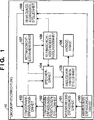
1 zeigt eine Darstellung eines Funktionsaufbaus einer Tomographievorrichtung gemäß einem Ausführungsbeispiel. 1 shows a representation of a functional structure of a tomography device according to an embodiment.
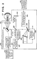
2 zeigt eine Darstellung eines Einrichtungsaufbaus und eines Funktionsaufbaus einer Tomogrammerfassungseinheit 103. 2 FIG. 10 is an illustration of a device structure and a functional structure of a tomogram detection unit. FIG 103 ,
3 zeigt ein Ablaufdiagramm einer Verarbeitungsprozedur gemäß dem Ausführungsbeispiel. 3 FIG. 12 is a flowchart showing a processing procedure according to the embodiment. FIG.
4 zeigt ein Ablaufdiagramm einer Verarbeitungsprozedur von Schritt S310. 4 FIG. 12 is a flowchart showing a processing procedure of step S310.
Die 5A und 5B zeigen Darstellungen, die jeweils einen OCT-Messbereich auf einem Fundus und dreidimensionale Daten veranschaulichen, die aufgenommen wurden.The 5A and 5B show representations each illustrating an OCT measurement area on a fundus and three-dimensional data taken.
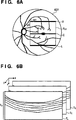
6A zeigt eine Darstellung von Tomogrammerfassungspositionen. 6A shows a representation of Tomogrammerfassungspositionen.
6B zeigt eine Darstellung von Tomogrammen, die erfasst wurden. 6B shows a representation of tomograms that have been detected.
7 zeigt eine Darstellung eines Beispiels eines Anzeigeverfahrens zur Anzeige von Tomogrammbilddaten in Reihe (ohne Abschnitt). 7 FIG. 12 is a diagram showing an example of a display method for displaying tomogram image data in series (without a section). FIG.
8 zeigt eine Darstellung eines Beispiels eines Anzeigeverfahrens zur Anzeige von Tomogrammbilddaten in Reihe (mit Abschnitt). 8th Fig. 12 is a diagram showing an example of a display method for displaying tomogram image data in series (with section).
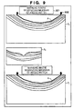
9 zeigt eine Darstellung einer Warnanzeige, die durchgeführt wird, wenn eine innere Begrenzungsmembran abgeschnitten wurde. 9 Fig. 12 is an illustration of a warning display performed when an inner restricting diaphragm has been cut off.
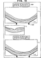
10 zeigt eine Darstellung einer Warnanzeige, die in einem Fall durchgeführt wird, wenn eine Retinapigmentepithelgrenze abgeschnitten wurde. 10 FIG. 12 is an illustration of a warning display performed in a case where a retinal pigment epithelial border has been cut off. FIG.
Die 11A und 11B zeigen Darstellungen der Positionsbeziehung zwischen einem Tomogramm und geschätzten Linien von Retinaschichten, die abgeschnitten wurden. The 11A and 11B Figures show the positional relationship between a tomogram and estimated lines of retinal tissue that were truncated.
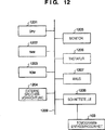
12 zeigt eine Darstellung eines Einrichtungsaufbaus der Tomographievorrichtung gemäß dem Ausführungsbeispiel. 12 FIG. 10 is an illustration of a device structure of the tomography apparatus according to the embodiment. FIG.
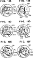
Die 13A bis 13F zeigen Darstellungen von Zentrumpositionen und Randabschnittpositionen, die Messbereichen entsprechen.The 13A to 13F show representations of center positions and edge portion positions corresponding to measurement ranges.
Die 14A und 14B zeigen Darstellungen zur Veranschaulichung des Abschnitts von Retinaschichten.The 14A and 14B show illustrations to illustrate the section of retinal layers.
BESCHREIBUNG DER AUSFÜHRUNGSBEISPIELEDESCRIPTION OF THE EMBODIMENTS
Ausführungsbeispiel 1Embodiment 1
Bei diesem Ausführungsbeispiel werden bei der Aufnahme eines Tomographiebildes eines Testsubjektauges mittels optischer Kohärenztomographie (die nachstehend als ”OCT” bezeichnet wird) Tomogramme angezeigt, während wiederholt eine Vielzahl von Stellen in einem Messbereich abgetastet werden, wodurch die Durchführung einer Anpassung ermöglicht wird, sodass der gesamte Soll-Messbereich in aufzunehmende Bilder passt. Insbesondere werden bei der erfindungsgemäßen Tomographievorrichtung bei der Betrachtung des Testsubjektauges vor der Aufnahme dreidimensionaler Daten bei der Diagnose mittels OCT Tomogramme an der Zentrumposition und Randabschnittpositionen eines Messbereichs RXY des Testsubjektauges erfasst, und die erfassten Tomogramme werden in Reihe auf einem Bestätigungsschirm in Echtzeit angezeigt. Da die dreidimensionale Form der Retina mittels eines Ellipsenkörpers genähert werden kann, gilt die Eigenschaft, dass bei einer Erhöhung der Entfernung nach außen von dem Zeitrum des Messbereichs RXY die Differenz zwischen dem Zentrum und einer Position in der Tiefen-(z-Achsen)Richtung der Retina monoton steigt. Gemäß dieser Eigenschaft ist es möglich, die Bedingung von Tomogrammen an der Zentrumposition und Randabschnittpositionen des Messbereichs RXY zu betrachten, was dem Fotografen immer ermöglicht, zu wissen, ob alle Retinaschichten in dreidimensionale Daten passen werden, die danach aufgenommen werden. Die Zentrumposition und Randabschnittpositionen des Messbereichs RXY, auf die hier Bezug genommen wird, sind jeweils die Position, die durch das Zentrum des Messbereichs RXY läuft, und Positionen, die den Bereich an den äußersten Rändern des Messbereichs RXY enthalten. Nachstehend werden mehrere spezifische Beispiele beschrieben.In this embodiment, when acquiring a tomographic image of a test subject eye by means of optical coherence tomography (hereinafter referred to as "OCT"), tomograms are displayed while repeatedly scanning a plurality of locations in a measurement area, thereby enabling the performance of fitting Target measuring range fits into pictures to be taken. Specifically, in the tomography apparatus of the present invention, when viewing the test subject eye before taking three-dimensional data in the diagnosis by OCT, tomograms at the center position and edge portion positions of a measurement range R XY of the test subject eye are detected, and the acquired tomograms are displayed in series on a confirmation screen in real time. Since the three-dimensional shape of the retina can be approximated by means of an ellipse body, the property that when increasing the distance outward from the time of the measurement area R XY, the difference between the center and a position in the depth (z-axis) direction the retina rises monotonously. According to this characteristic, it is possible to consider the condition of tomograms at the center position and edge portion positions of the measurement range R XY , which always allows the photographer to know whether all retinal layers will fit into three-dimensional data taken thereafter. The center position and edge portion positions of the measurement range R XY referred to herein are respectively the position passing through the center of the measurement range R XY and positions including the range at the outermost edges of the measurement range R XY . Hereinafter, several specific examples will be described.
Die 13A bis 13F zeigen Darstellungen von Zentrumpositionen und Randabschnittpositionen, die dem Messbereich RXY entsprechen. Die 13A und 13B zeigen zwei Typen von Darstellungen, die die Zentrumposition und Randabschnittpositionen in dem Fall darstellen, wenn der Messbereich RXY ein Rechteck ist. Die 13C und 13D zeigen zwei Typen von Darstellungen, die die Zentrumposition und Randabschnittpositionen in dem Fall zeigen, wenn der Messbereich RXY ein Parallelogramm ist. Die 13E und 13F zeigen zwei Typen von Darstellungen, die die Zentrumposition und eine Randabschnittposition in dem Fall darstellen, wenn der Messbereich RXY ein Kreis ist. In den Darstellungen 13A bis 13F bezeichnet 1301 ein Fundusbild und RXY bezeichnet einen zweidimensionalen Messbereich. Auch bezeichnen 1302, 1306, 1310, 1314, 1318 und 1321 Zentrumpositionen des Messbereichs RXY. Des Weiteren bezeichnen 1303 und 1304, 1307 und 1308, 1311 und 1312, 1315 und 1316, und 1319 und 1322 Randabschnittpositionen. Des Weiteren bezeichnen P1, P2, P3 und P4 in den 13C und 13D die vier Scheitelpunkte des Messbereichs RXY.The 13A to 13F show representations of center positions and edge portion positions corresponding to the measurement range R XY . The 13A and 13B show two types of representations representing the center position and edge portion positions in the case where the measurement range R XY is a rectangle. The 13C and 13D show two types of representations showing the center position and edge portion positions in the case where the measurement range R XY is a parallelogram. The 13E and 13F show two types of representations representing the center position and an edge portion position in the case where the measurement range R XY is a circle. In the illustrations 13A to 13F designated 1301 a fundus image and R XY denotes a two-dimensional measurement range. Also designate 1302 . 1306 . 1310 . 1314 . 1318 and 1321 Center positions of the measuring range R XY . Furthermore, denote 1303 and 1304 . 1307 and 1308 . 1311 and 1312 . 1315 and 1316 , and 1319 and 1322 Edge section positions. Further, P 1 , P 2 , P 3 and P 4 denote the 13C and 13D the four vertices of the measuring range R XY .
Hier sind die Zentrumpositionen und Randabschnittpositionen in diesen Figuren alle Positionen, die die vorstehend angeführten Definitionen erfüllen. Für den Fall, dass der Messbereich RXY ein Rechteck ist, können die Zentrumposition und die Randabschnittpositionen Liniensegmente sein, die parallel zur x-Achse sind, wie es in 13A gezeigt ist, oder können Liniensegmente parallel zur y-Achse sein, wie es in 13B gezeigt ist. Ist der Messbereich RXY ein Parallelogramm, können die Zentrumposition und die Randabschnittpositionen Liniensegmente parallel zu einer Seite P1P4 wie in 13C gezeigt oder Liniensegmente parallel zu einer Seite P1P2 wie in 13D gezeigt sein.Here, the center positions and edge portion positions in these figures are all positions that satisfy the definitions given above. In the case where the measurement range R XY is a rectangle, the center position and the edge portion positions may be line segments that are parallel to the x-axis as shown in FIG 13A is shown, or may be line segments parallel to the y-axis as shown in FIG 13B is shown. If the measurement range R XY is a parallelogram, the center position and the edge portion positions may be line segments parallel to a side P 1 P 4 as in FIG 13C shown or line segments parallel to a side P 1 P 2 as in 13D be shown.
Ist der Messbereich RXY ein Kreis, kann die Zentrumposition des Messbereichs RXY ein Liniensegment parallel zur x-Achse wie in 13E oder ein Liniensegment parallel zur y-Achse wie in 13F gezeigt sein. Hier ist die Randabschnittposition eine dem Kreisumfang des Messbereichs RXY entsprechende Position. Das heißt, es wird ein durch Kreisabtastung erhaltenes Tomogramm verwendet. Obwohl dieses Ausführungsbeispiel nachstehend anhand des bestimmten Beispiels des in 13A gezeigten Falls beschrieben wird, sind die Form des Messbereichs und die Zentrumposition und Randabschnittpositionen nicht auf dieses Beispiel beschränkt.If the measuring range R XY is a circle, the center position of the measuring range R XY can be a line segment parallel to the x-axis as in 13E or a line segment parallel to the y-axis as in 13F be shown. Here, the edge portion position is a position corresponding to the circumference of the measurement range R XY . That is, a tomogram obtained by circular scanning is used. Although this embodiment is described below with reference to the specific example of the in 13A As described, the shape of the measuring area and the center position and edge portion positions are not limited to this example.
Durch die Anzeige von Tomogrammen an der Zentrumposition und zwei Randabschnittpositionen in Echtzeit kann ein Benutzer leicht bestimmen, ob eine Retinaschicht aus dem Messbereich in der Tiefenrichtung hinaussteht (bezüglich der Tiefenrichtung abgeschnitten wurde). Da der OCT-Referenzspiegel während der Betrachtung der Tomogramme an dem Mittelpunktabschnitt und zwei Randabschnitten, die in Echtzeit angezeigt werden, bewegt werden kann, kann der Benutzer den Referenzspiegel leicht auf eine geeignete Position einstellen. Ferner wird erfasst, ob eine Retinaschicht in der Tiefenrichtung des Messbereichs in dem Tomogramm abgeschnitten wurde, und wurde eine Retinaschicht abgeschnitten, wird eine entsprechende Warnung präsentiert, wodurch dem Fotografen zur Kenntnis gebracht werden kann, dass eine Retinaschicht abgeschnitten wurde. Hier wird das Abschneiden einer Retinaschicht in der Tiefenrichtung beispielsweise durch die Bestimmung erfasst, ob die Retinaschicht die obere Seite oder untere Seite des Tomogramms berührt oder schneidet. Ferner wird die Möglichkeit bereitgestellt, die Position der Retinaschicht in dem Tomogramm zu erfassen und die Messtiefe in der z-Achsenrichtung automatisch anzupassen, sodass die Retinaschicht im Tomogramm nicht abgeschnitten wird, wodurch diese Last vom Fotografen genommen wird und ferner Abbildungsfehler verhindert werden. Nachstehend wird ein bestimmtes Beispiel beschrieben.By displaying tomograms at the center position and two edge portion positions in real time, a user can easily determine whether a retinal layer protrudes from the measurement area in the depth direction (with respect to the depth direction was cut off). Since the OCT reference mirror can be moved while observing the tomograms at the midpoint portion and two edge portions displayed in real time, the user can easily adjust the reference mirror to an appropriate position. Further, it is detected whether a retinal layer has been cut in the depth direction of the measurement area in the tomogram, and if a retinal layer has been cut off, a corresponding warning is presented, whereby the photographer can be made aware that a retinal layer has been cut off. Here, the cutting of a retinal layer in the depth direction is detected, for example, by determining whether the retinal layer touches or cuts the upper side or lower side of the tomogram. Further provided is the ability to detect the position of the retinal layer in the tomogram and to automatically adjust the measurement depth in the z-axis direction so that the retinal layer is not truncated in the tomogram, thereby removing that load from the photographer and further preventing aberrations. Hereinafter, a specific example will be described.
Die 14A und 14B zeigen Darstellungen zur Veranschaulichung eines Abschneidens von Retinaschichten. Die 14A und 14B veranschaulichen jeweils Beispiele, bei denen Retinaschichten an der oberen Seite und der unteren Seite von Tomogrammen abgeschnitten wurden. Hier bezeichnen 1401 und 1402, die jeweils in den 14A und 14B gezeigt sind, Tomogramme, bei denen Retinaschichten in den in diesen Fällen gezeigten Bildern abgeschnitten wurden. In diesen Figuren ist die x-Achse die Hauptabtastrichtung und die z-Achse ist die A-Abtastrichtung. In diesen Figuren ist der Bereich der Koordinaten in den Tomogrammen 0 ≤ x ≤ xmax und 0 ≤ z ≤ zmax. In 14A bezeichnet A die innere Begrenzungsmembran des Fundus. In 14A schneidet die innere Begrenzungsmembran A die Gerade an z = 0 (obere Seite des Tomogramms), und daher zeigt 14A die Bedingung, bei der die innere Begrenzungsmembran A abgeschnitten wurde. In 14B bezeichnet B die Retinapigmentepithelgrenze. In 14B schneidet die Retinapigmentepithelgrenze B die Gerade an z = zmax (untere Seite des Tomogramms), und daher zeigt 14B die Bedingung, bei der die Retinapigmentepithelgrenze B abgeschnitten wurde. Auf diese Weise bezieht sich das Abschneiden einer Retinaschicht bei diesem Ausführungsbeispiel insbesondere auf das Abschneiden der inneren Begrenzungsmembran oder der Retinapigmentepithelgrenze.The 14A and 14B show illustrations to illustrate a trimming of retinal layers. The 14A and 14B each illustrate examples in which retinal layers at the top and bottom of tomograms were cut off. Denote here 1401 and 1402 , respectively in the 14A and 14B are shown tomograms in which retinal layers were cut in the images shown in these cases. In these figures, the x-axis is the main scanning direction and the z-axis is the A-scanning direction. In these figures, the range of coordinates in the tomograms is 0 ≦ x ≦ x max and 0 ≦ z ≦ z max . In 14A A denotes the inner boundary membrane of the fundus. In 14A the inner limiting diaphragm A cuts the straight line at z = 0 (upper side of the tomogram), and therefore shows 14A the condition in which the inner restricting diaphragm A was cut off. In 14B B denotes the retinal pigment epithelial border. In 14B the retinal pigment epithelial border B intersects the straight line z = z max (lower side of the tomogram), and therefore shows 14B the condition in which the retinal pigment epithelial border B was cut off. In this way, the cutting of a retinal layer in this embodiment particularly relates to the cutting of the inner limiting membrane or the retinal pigment epithelial border.
Als nächstes wird ein Aufbau der Tomographievorrichtung 10 gemäß dem Ausführungsbeispiel und bestimmter durch die Tomographievorrichtung 10 ausgeführter Verarbeitungsprozeduren unter Bezugnahme auf das Blockschaltbild in 1 und das Ablaufdiagramm in 3 beschrieben.Next, a construction of the tomographic apparatus will be described 10 according to the embodiment and in particular by the tomography device 10 executed processing procedures with reference to the block diagram in 1 and the flowchart in FIG 3 described.
In Schritt S301 erfasst eine Messbereicherfassungseinheit 101 von einer Anweisungserfassungseinheit 100 Anweisungsinformationen von einem Bediener, die zur Einstellung des zweidimensionalen Messbereichs RXY auf dem Fundus eines Testsubjekts dienen, und bestimmt den Messbereich RXY. Diese Anweisungsinformationen werden vom Bediener über eine Tastatur oder eine Maus (nicht gezeigt) eingegeben, mit denen die Tomographievorrichtung 10 versehen ist. Als ein Beispiel der Anweisung hinsichtlich des Messbereichs RXY auf dem Fundus erfasst die Messbereicherfassungseinheit 101 eine (als Anweisung 1 definierte) Anweisung, wie eine Bestimmung eines Orts oder einer Position auf dem Fundus, auf den die Tomogrammerfassung abzielt. Dann bestimmt die Messbereicherfassungseinheit 101 den Messbereich RXY beruhend auf dem Inhalt dieser Anweisung 1, der ein Rechteck ist. Der bestimmte Messbereich RXY wird zu einer Tomogrammerfassungspositionseinstelleinheit 102 übertragen.In step S301, a measuring range detecting unit detects 101 from an instruction acquisition unit 100 Instruction information from an operator used to set the two-dimensional measurement range R XY on the fundus of a test subject, and determines the measurement range R XY . This instruction information is entered by the operator via a keyboard or mouse (not shown) with which the tomography device 10 is provided. As an example of the instruction regarding the measurement range R XY on the fundus, the measurement range detection unit detects 101 an instruction (defined as instruction 1), such as a determination of a location or position on the fundus targeted by the tomogram acquisition. Then, the measuring range detecting unit determines 101 the measurement range R XY based on the content of this instruction 1, which is a rectangle. The specific measuring range R XY becomes a tomogram detection position setting unit 102 transfer.
In Schritt S302 erhält die Tomogrammerfassungspositionseinstelleinheit 102 den Messbereich RXY von der Messbereicherfassungseinheit 101 und stellt Positionen ein, wo Tomogramme innerhalb des Messbereichs zu erfassen sind (die nachstehend als Tomogrammerfassungspositionen P bezeichnet werden). Eine vorbestimmte Anzahl von Positionen wird als die Tomogrammerfassungspositionen P eingestellt, und diese Anzahl ist geringer als im Fall der Durchführung einer Abbildung für eine Diagnose. In diesem Schritt werden beispielsweise die Zentrumposition und Randabschnittpositionen des Messbereichs RXY als die Tomogrammerfassungspositionen P eingestellt. Die Tomogrammerfassungspositionen P sind natürlich nicht auf diese Kombination beschränkt. Beispielsweise können fünf Tomogrammerfassungspositionen P durch Hinzufügen einer Erfassungsposition zwischen dem Zentrum und jedem der zwei Randabschnitte eingestellt werden.In step S302, the tomogram detection position setting unit obtains 102 the measuring range R XY of the measuring range detection unit 101 and sets positions where tomograms are to be detected within the measurement range (which will be referred to as tomogram detection positions P hereinafter). A predetermined number of positions are set as the tomogram detection positions P, and this number is smaller than in the case of performing a map for diagnosis. In this step, for example, the center position and edge portion positions of the measurement area R XY are set as the tomogram detection positions P. Of course, the tomographic detection positions P are not limited to this combination. For example, five tomographic detection positions P can be set by adding a detection position between the center and each of the two edge portions.
6A zeigt eine Darstellung der Tomogrammerfassungspositionen P in dem Messbereich RXY. Hier bezeichnet 601 das Fundusbild und RXY im Fundusbild 601 bezeichnet den zweidimensionalen Messbereich. 10 im Messbereich RXY bezeichnet ein Liniensegment (das nachstehend als die Zentrumposition bezeichnet wird), das durch das Zentrum des Messbereichs RXY läuft und parallel zur x-Achse in der Figur ist, U bezeichnet die obere Seite des Messbereichs RXY (die nachstehend als die obere Randposition bezeichnet wird), und L bezeichnet die untere Seite des Messbereichs RXY (die nachstehend als der untere Randabschnitt bezeichnet wird). Bei diesem Ausführungsbeispiel werden drei Positionen an dem Zentrumabschnitt C, oberen Randabschnitt U und unteren Randabschnitt L des Messbereichs RXY als die den Zentrumabschnitt und die zwei Randabschnitte des Messbereichs RXY angebenden Positionen angewendet. Diese Positionen entsprechen 13A (1302 bis 1304). Wenn Tomogramme wie nachstehend beschrieben erfasst werden, werden der Bereich des Messbereichs RZ in der z-Achsenrichtung dieser Positionen an dem Zentrumabschnitt C, dem oberen Randabschnitt U und dem unteren Randabschnitt L zur Erfassung der Tomogramme abgetastet. Allerdings sind die Positionen des Zentrums und der Randabschnitte des Messbereichs RXY wie vorstehend angeführt nicht auf diese beschriebenen Positionen beschränkt, und diese Positionen können Positionen wie in den 13B bis 13F gezeigt sein. Die Tomogrammerfassungspositionen P (der Zentrumabschnitt C, der obere Randabschnitt U und der untere Randabschnitt L), die auf diese Weise eingestellt werden, werden zu einer Tomogrammerfassungseinheit 103 übertragen. 6A shows a representation of the Tomogrammerfassungspositionen P in the measuring range R XY . Designated here 601 the fundus image and R XY in the fundus image 601 denotes the two-dimensional measuring range. 10 in the measuring range R XY denotes a line segment (hereinafter referred to as the center position) passing through the center of the measuring range R XY and parallel to the x-axis in the figure, U denotes the upper side of the measuring range R XY (hereinafter referred to as the upper edge position is designated), and L denotes the lower side of the measuring range R XY (which will be referred to as the lower edge portion hereinafter). In this embodiment, three positions at the center portion C, upper edge portion U, and lower edge portion L of the measurement range R XY than the applied to the center portion and the two edge portions of the measuring range R XY indicating positions. These positions correspond 13A ( 1302 to 1304 ). When tomograms are detected as described below, the range of the measurement range R Z in the z-axis direction of these positions is sampled at the center portion C, the top edge portion U and the bottom edge portion L for acquiring the tomograms. However, the positions of the center and edge portions of the measurement area R XY are not limited to these described positions as mentioned above, and these positions may be positions as in FIGS 13B to 13F be shown. The tomogram detection positions P (the center portion C, the top edge portion U and the bottom edge portion L) set in this manner become a tomogram detection unit 103 transfer.
In Schritt S303 erhält eine Bewegungsausmaßeinstelleinheit 109 von der Anweisungserfassungseinheit 100 Anweisungsinformationen vom Bediener, die zur manuellen Einstellung einer Messposition in der Tiefenrichtung der Retina dienen. Diese Anweisung wird durch den Bediener mittels einer Benutzerschnittstelle eingegeben, die nicht gezeigt ist. Als ein Beispiel der Anweisung zur Einstellung der Messposition erfasst die Bewegungsausmaßeinstelleinheit 109 ein Bewegungsausmaß (das nachstehend als Tiefenrichtungsbewegungsausmaß D bezeichnet wird), mit dem die Messposition in der Tiefenrichtung (z-Achsenrichtung) zu bewegen ist. Das Tiefenrichtungsbewegungsausmaß D, das eingestellt wurde, wird dann zu der Tomogrammerfassungseinheit 103 übertragen.In step S303, a movement amount setting unit is obtained 109 from the instruction acquisition unit 100 Instruction information from the operator used to manually set a measurement position in the depth direction of the retina. This instruction is entered by the operator via a user interface, which is not shown. As an example of the instruction for setting the measurement position, the movement amount setting unit detects 109 a movement amount (to be referred to as depth direction movement amount D hereinafter) with which the measurement position is to be moved in the depth direction (z-axis direction). The depth direction movement amount D that has been set then becomes the tomogram detection unit 103 transfer.
In Schritt S303 erfasst die Tomogrammerfassungseinheit 103 Tomogramme des Testsubjektauges beruhend auf den von der Tomogrammerfassungspositionseinstelleinheit 102 erfassten Tomogrammerfassungspositionen P und dem von der Bewegungsausmaßeinstelleinheit 109 erfassten Tiefenrichtungsbewegungsausmaß D.In step S303, the tomogram detection unit detects 103 Tomograms of the test subject eye based on that from the tomogram detection position setting unit 102 detected tomographic detection positions P and the movement amount setting unit 109 detected depth direction movement amount D.
Bei diesem Ausführungsbeispiel wendet die Tomogrammerfassungseinheit 103 ein OCT-Verfahren im Fourier-Bereich an. 2 zeigt ein Beispiel eines Funktionsaufbaus und eines Einrichtungsaufbaus der Tomogrammerfassungseinheit 103. Die Tomogrammerfassungseinheit 103 steuert eine galvanische Spiegelansteuereinrichtung 203 entsprechend den Tomogrammerfassungspositionen P und steuert so einen galvanischen Spiegel 203 an. Die galvanische Spiegelansteuereinrichtung 203 steuert den galvanischen Spiegel 204 derart an, dass Signallicht in der Hauptabtastrichtung und der Unterabtastrichtung (der x-Achsenrichtung und der y-Achsenrichtung in 6A) abgetastet wird. Da hier Tomogramme in Echtzeit an den drei Positionen an der Zentrumposition C, der oberen Randposition U und der unteren Randposition L in 6A aufgenommen werden, wird die Steuerung derart durchgeführt, dass diese drei Positionen bei der Hauptabtastung gleichzeitig auf einmal abgetastet werden. Insbesondere wird die Steuerung derart durchgeführt, dass durch Umschalten der Abtastposition in der Unterabtastrichtung zwischen der Zentrumposition C, der oberen Randposition U und der unteren Randposition L mit hoher Geschwindigkeit eine Abtastung in der Hauptabtastrichtung mit einem Abtastintervall von 1/3 hinsichtlich des Falls der Durchführung einer Hauptabtastung durchgeführt wird, bei der die Unterabtastposition fest ist. Auch steuert die Tomogrammerfassungseinheit 103 eine Referenzspiegelansteuereinrichtung 209 entsprechend dem Tiefenrichtungsbewegungsausmaß D, wodurch ein Referenzspiegel 202 angesteuert wird.In this embodiment, the tomogram detection unit uses 103 an OCT method in the Fourier range. 2 shows an example of a functional structure and a device structure of the tomographic detection unit 103 , The Tomogrammerfassungseinheit 103 controls a galvanic Spiegelansteuereinrichtung 203 corresponding to the tomogram detection positions P and thus controls a galvanic mirror 203 at. The galvanic mirror drive device 203 controls the galvanic mirror 204 such that signal light in the main scanning direction and the sub-scanning direction (the x-axis direction and the y-axis direction in FIG 6A ) is scanned. Since here tomograms in real time at the three positions at the center position C, the upper edge position U and the lower edge position L in 6A are taken, the control is performed such that these three positions are scanned simultaneously in the main scan at one time. Specifically, the control is performed such that by switching the scanning position in the sub-scanning direction between the center position C, the upper edge position U and the lower edge position L at high speed, scanning in the main scanning direction with a sampling interval of 1/3 in the case of performing a Main scan is performed, in which the sub-scanning is fixed. Also controls the Tomogrammerfassungseinheit 103 a reference mirror driver 209 corresponding to the depth direction movement amount D, thereby providing a reference mirror 202 is controlled.
Ein Lichtstrahl von einer Lichtquelle mit niedriger Kohärenz 200 wird durch einen Halbspiegel 201 in Signallicht, das zu einem Messobjekt 211 über eine Objektivlinse 210 läuft, und Referenzlicht geteilt, das zu dem Referenzspiegel 202 läuft. Als nächstes wird Störlicht durch Überlagern des Signallichts und Referenzlichts erzeugt, das jeweils durch das Messobjekt 211 und den Referenzspiegel 202 reflektiert wurde. Dieses Störlicht wird mittels eines Beugungsgitters 205 in Wellenlängenkomponenten mit Wellenlängen von λ1 bis λn separiert, und die Wellenlängenkomponenten werden durch ein eindimensionales optisches Sensorarray 206 erfasst. Das eindimensionale optische Sensorarray 206 ist durch optische Sensoren gebildet, die die Lichtintensität der erfassten Wellenlängekomponenten angebende Erfassungssignale zu einer Bildrekonstruktionseinheit 208 ausgeben.A beam of light from a low-coherence light source 200 is through a half mirror 201 in signal light, that becomes a measuring object 211 via an objective lens 210 runs, and reference light is shared, leading to the reference mirror 202 running. Next, stray light is generated by superimposing the signal light and reference light respectively through the measurement object 211 and the reference mirror 202 was reflected. This stray light is detected by means of a diffraction grating 205 are separated into wavelength components having wavelengths from λ1 to λn, and the wavelength components are separated by a one-dimensional optical sensor array 206 detected. The one-dimensional optical sensor array 206 is formed by optical sensors, the detection signals indicating the light intensity of the detected wavelength components to an image reconstruction unit 208 output.
Beruhend auf den erfassten Signalen hinsichtlich der Wellenlängenkomponenten des Störlichts, die von dem eindimensionalen optischen Sensorarray 206 ausgegeben wurden, erhält die Bildrekonstruktionseinheit 208 die Beziehung zwischen Wellenlänge und Lichtintensität für das Störlicht, d. h., die Lichtintensitätsverteilung (Wellenlängenspektrum) des Störlichts. Auf das erhaltene Störlichtwellenlängenspektrum wird die inverse Fourier-Transformation angewendet, und ein Tomogramm der Retina wird rekonstruiert.Based on the detected signals with respect to the wavelength components of the disturbing light emitted by the one-dimensional optical sensor array 206 are issued receives the image reconstruction unit 208 the relationship between wavelength and light intensity for the stray light, that is, the light intensity distribution (wavelength spectrum) of the stray light. The inverse Fourier transform is applied to the obtained interfering light wavelength spectrum, and a retinal tomogram is reconstructed.
6B zeigt eine Darstellung von Tomogrammen, die an dem Zentrumabschnitt C, dem oberen Randabschnitt U und dem unteren Randabschnitt L erfasst wurden. Hier bezeichnet RZ den eindimensionalen Messbereich in der z-Achsenrichtung, ähnlich wie 5B. Der Messbereich RZ ist ein Bereich in der Tiefenrichtung des Tomogramms und wird beruhend auf der Position bestimmt, an die der Referenzspiegel 202 gesteuert bewegt wurde. In 6B bezeichnet TC ein dem Zentrumabschnitt C in 6A entsprechendes Tomogramm (das nachstehend als das Zentrumabschnitttomogramm bezeichnet wird), TU bezeichnet ein dem oberen Randabschnitt U in 6A entsprechendes Tomogramm (das nachstehend als das obere Randabschnitttomogramm bezeichnet wird), und TL bezeichnet ein dem unteren Randabschnitt L in 6A entsprechendes Tomogramm (das nachstehend als das untere Randabschnitttomogramm bezeichnet wird). Die Bilddaten der aufgenommenen Tomogramme werden zu einer Speichereinheit 104 übertragen. 6B FIG. 11 is a diagram of tomograms detected at the center portion C, the upper edge portion U, and the lower edge portion L. FIG. Here, R Z denotes the one-dimensional measurement range in the z-axis direction, similarly to 5B , The measurement range R Z is an area in the depth direction of the tomogram and is determined based on the position to which the reference mirror 202 was moved controlled. In 6B T C denotes a center portion C in FIG 6A corresponding tomogram (hereinafter referred to as the center portion tomogram is designated), T U denotes a top edge portion U in 6A corresponding tomogram (hereinafter referred to as the upper edge portion tomogram), and T L denotes a lower edge portion L in FIG 6A corresponding tomogram (hereinafter referred to as the lower edge portion tomogram). The image data of the acquired tomograms become a storage unit 104 transfer.
Als nächstes erfasst eine Anzeigeverfahreneinstelleinheit 105 in Schritt S305 die in der Speichereinheit 104 gespeicherten Tomogrammbilddaten und stellt ein Anzeigenerfahren zur gleichzeitigen Anzeige der Tomogrammbilddaten in Reihe (das als Anzeigeverfahren 1 definiert ist) ein.Next, a display method setting unit detects 105 in step S305, those in the storage unit 104 stored tomogram image data and sets a display method for simultaneously displaying the tomogram image data in series (which is defined as display method 1).
7 zeigt ein Beispiel einer Anzeige entsprechend dem Anzeigeverfahren 1. Hier bezeichnet TU das obere Randabschnitttomogramm, TC bezeichnet das Zentrumabschnitttomogramm und TL bezeichnet das untere Randabschnitttomogramm. Wie in 5B bezeichnet A die innere Begrenzungsmembran in den Tomogrammen und B bezeichnet die Retinapigmentepithelgrenze. Wie in 7 gezeigt ist das bei diesem Ausführungsbeispiel angewendete Verfahren ein Verfahren, bei dem das obere Randabschnitttomogramm TU, das Zentrumabschnitttomogramm TC und das untere Randabschnitttomogramm TL in Reihe bzw. zeilenweise von oben in der genannten Reihenfolge angezeigt werden. Allerdings ist das Tomogrammanzeigeverfahren nicht darauf beschränkt, und kann ein beliebiges Verfahren sein, das eine gleichzeitige Überprüfung der Tomogramme in einer In-Reihe-Bedingung ermöglicht. Beispielsweise können diese Tomogramme horizontal oder diagonal aufgereiht angezeigt werden. Zudem zeigt 8 ein Beispiel einer Anzeige entsprechend dem Anzeigeverfahren 1 in dem Fall, wenn Retinaschichten abgeschnitten wurden. Wie in 7 bezeichnen TU, TC, TL, A und B in 8 das obere Randabschnitttomogramm, das Zentrumabschnitttomogramm, das untere Randabschnitttomogramm, die innere Begrenzungsmembran und die Retinapigmentepithelgrenze. In 8 wurde die innere Begrenzungsmembran A an der oberen Seite im oberen Randabschnitttomogramm TU und dem unteren Randabschnitttomogramm TL abgeschnitten. Die Richtung, in der die Tomogramme aufgereiht sind, ist die gleiche wie in 7. 7 Fig. 10 shows an example of a display according to the display method 1. Here, T U denotes the upper edge portion tomogram, T C denotes the center portion tomogram, and T L denotes the lower edge portion tomogram. As in 5B A denotes the inner boundary membrane in the tomograms and B denotes the retinal pigment epithelial border. As in 7 That is, the method used in this embodiment is a method in which the upper edge portion tomogram T U , the center portion tomogram T C, and the lower edge portion tomogram T L are displayed in a row from above in the order named. However, the tomogram display method is not limited to this, and may be any method that enables concurrent checking of the tomograms in an in-line condition. For example, these tomograms can be displayed horizontally or diagonally. In addition shows 8th an example of a display according to the display method 1 in the case when retinal layers were cut off. As in 7 denote T U , T C , T L , A and B in 8th the upper edge portion tomogram, the center portion tomogram, the lower edge portion tomogram, the inner boundary membrane, and the retinal pigment epithelial border. In 8th For example, the inner boundary membrane A at the upper side in the upper edge portion tomogram T U and the lower edge portion tomogram T L has been cut off. The direction in which the tomograms are lined up is the same as in 7 ,
Auf diese Weise kann der Benutzer durch das Anzeigen der Tomogramme an dem Zentrumabschnitt und den Randabschnitten in Reihe überprüfen, ob eine Retinaschicht in einem Tomogramm abgeschnitten wurde, wodurch dem Benutzer die Bestimmung ermöglicht wird, ob eine Retinaschicht in nach der Abbildung erhaltenen dreidimensionalen Daten abgeschnitten sein wird. Die Daten hinsichtlich des Anzeigeverfahrens 1, das eingestellt wurde, und die Tomogrammbilddaten, die anzuzeigen sind, werden zu einer Anzeigeeinheit 106 übertragen.In this way, by displaying the tomograms at the center portion and the edge portions in series, the user can check whether a retinal layer has been cut off in a tomogram, thereby enabling the user to determine whether a retinal layer in three-dimensional data obtained after imaging is cut off becomes. The data regarding the display method 1 that has been set and the tomogram image data to be displayed become a display unit 106 transfer.
Die Verarbeitung von Schritt S306 bis Schritt S308 ist eine Verarbeitung, bei der ein Abschneiden einer Retinaschicht in einem Tomogramm erfasst wird, und eine Warnung angezeigt wird, indem die Anzeigeform des Tomogramms, in dem das Abschneiden erfasst wurde, von der der anderen Tomogramme verschieden gemacht wird. Zuerst erfasst eine Retinaschichtextrahiereinheit 107 in Schritt S306 die in der Speichereinheit 104 gespeicherten Tomogrammbilddaten und extrahiert Retinaschichten aus jedem der Tomogramme mittels einer Bildanalyse.The processing from step S306 to step S308 is a processing in which a clipping of a retinal layer in a tomogram is detected, and a warning is displayed by making the display form of the tomogram in which the clipping was detected different from that of the other tomograms becomes. First detects a retinal layer extraction unit 107 in step S306, those in the storage unit 104 stored tomogram image data and extracts retinal layers from each of the tomograms by means of an image analysis.
In diesem Schritt werden zwei Schichten, d. h., die innere Begrenzungsmembran A und die Retinapigmentepithelgrenze B in 7 als die Retinaschichten extrahiert. Die innere Begrenzungsmembran A ist eine Grenze, die zwischen einem Glaskörperbereich an der oberen Seite, der als niedriger Luminanzbereich in dem Bild extrahiert wird, und einer Nervenfaserschicht an der unteren Seite eingeklemmt ist, die als hoher Luminanzbereich extrahiert wird, und daher hat die innere Begrenzungsmembran A die Eigenschaft, dass der Luminanzgradient groß ist. In Anbetracht dessen werden bei diesem Ausführungsbeispiel interessierende Bildelemente in einer A-Abtastlinie der Reihe nach in der positiven z-Achsenrichtung beginnend von dem oberen Rand des Bildes abgetastet, und eine Position, an der der Gradient in dem Bild in der Nähe des interessierenden Bildelements einen bestimmten Schwellenwert TA überschreitet, wird erfasst, wodurch das Bildelement an der erfassten Position als Bildelement extrahiert wird, das der inneren Begrenzungsmembran A entspricht. Dies wird für alle A-Abtastlinien wiederholt, wodurch die innere Begrenzungsmembran aus dem Tomogramm extrahiert wird.In this step, two layers, ie, the inner boundary membrane A and the retinal pigment epithelial boundary B in FIG 7 as the retinal layers extracted. The inner boundary membrane A is a boundary sandwiched between a vitreous body region on the upper side extracted as a low luminance region in the image and a nerve fiber layer on the lower side extracted as a high luminance region, and hence the inner constraint membrane A is the property that the luminance gradient is large. In view of this, in this embodiment, pixels of interest in an A-scan line are sequentially scanned in the positive z-axis direction starting from the upper edge of the image, and a position where the gradient in the image in the vicinity of the pixel of interest certain threshold value T A is detected, whereby the picture element is extracted at the detected position as a picture element corresponding to the inner limiting diaphragm A. This is repeated for all A scan lines, extracting the inner boundary diaphragm from the tomogram.
Zudem wird ein Bereich (das Retinapigmentepithel), der zwischen der Retinapigmentepithelgrenze B und der Fotorezeptor-Innensegment/Außensegment-Verbindung (IS/OS), die eine Grenze eine Stufe darüber ist, eingeschlossen ist, als besonders hoher Luminanzbereich innerhalb der Retinaschichten extrahiert. Da der Bereich über der IS/OS verglichen mit diesem Bereich eine relativ niedrige Luminanz aufweist, hat die IS/OS die Eigenschaft, dass der Luminanzgradient in dem Bild groß ist. In Anbetracht dessen werden bei diesem Ausführungsbeispiel interessierende Bildelemente in einer A-Abtastlinie in der positiven z-Achsenrichtung unter Verwendung der extrahierten Position der inneren Begrenzungsmembran A als Ursprung abgetastet, und eine Position wird erfasst, an der der Gradient in dem Bild in der Nähe des interessierenden Bildelements einen bestimmten Schwellenwert TI überschreitet, wodurch das Bildelement an der erfassten Position als der IS/OS entsprechendes Bildelement extrahiert wird. Dies wird für alte A-Abtastlinien wiederholt, wodurch die IS/OS-Schicht aus dem Tomogramm extrahiert wird.In addition, a region (the retinal pigment epithelium) sandwiched between the retinal pigment epithelial border B and the photoreceptor inner segment / outer segment compound (IS / OS), which is a boundary one step above, is extracted as a particularly high luminance region within the retinal layers. Since the area over the IS / OS has a relatively low luminance compared with this area, the IS / OS has a property that the luminance gradient in the image is large. In view of this, in this embodiment, pixels of interest in an A-scan line are scanned in the z-axis positive direction using the extracted position of the inner restricting diaphragm A as an origin, and a position is detected where the gradient in the image is near the pixel of interest exceeds a certain threshold T I , whereby the pixel at the sensed position as the IS / OS corresponding picture element is extracted. This is repeated for old A scan lines, which extracts the IS / OS layer from the tomogram.
Dann werden interessierende Bildelemente in einer A-Abtastlinie ferner in der positiven z-Achsenrichtung unter Verwendung der IS/OS als Ursprung abgetastet, und es wird eine Position erfasst, an der der Luminanzwert geringer als ein bestimmter Schwellenwert TB ist, wodurch das Bildelement an der erfassten Position als Bildelement extrahiert wird, das der Retinapigmentepithelgrenze entspricht. Dies wird für alle A-Abtastlinien wiederholt, wodurch die Retinapigmentepithelgrenze B extrahiert wird. Dann werden die Tomogrammbilddaten und extrahierten Retinaschichtdaten (drei Stück Grenzdaten für die innere Begrenzungsmembran, die IS/OS und die Retinapigmentepithelgrenze) zu einer Retinaschichtabschneideerfassungseinheit 108 übertragen.Then, pixels of interest in an A-scan line are further scanned in the z-axis positive direction using the IS / OS as the origin, and a position where the luminance value is less than a predetermined threshold T B is detected, thereby causing the pixel of the detected position is extracted as a picture element corresponding to the retinal pigment epithelial border. This is repeated for all A scan lines, thereby extracting the retinal pigment epithelial boundary B. Then, the tomogram image data and extracted retinal layer data (three pieces of boundary data for the inner boundary membrane, the IS / OS, and the retinal pigment epithelial border) become a retinal cut-off detection unit 108 transfer.
In Schritt S307 erfasst die Retinaschichtabschneideerfassungseinheit 108 ein Abschneiden einer Retinaschicht beruhend auf den Tomogrammbilddaten und den von der Retinaschichtextraktionseinheit 107 erhaltenen Retinaschichtdaten und erzeugt Retinaschichtdaten, in denen ein Abschneiden einer Retinaschicht erfasst wurde. Diese Daten sind als Retinaschichtabschneideerfassungsdaten definiert. Wird ein Abschneiden erfasst, d. h., die Tatsache, dass eine Retinaschicht aus dem Messbereich in der Tiefenrichtung hinaussteht, wird ein Flag auf wahr gesetzt, das angibt, dass eine Retinaschicht abgeschnitten wurde, und wurde kein Abschneiden erfasst, wird das Flag auf falsch gesetzt. Dieses Flag ist als Abschneideerfassungsflag E definiert. Ist das Abschneideerfassungsflag E wahr, werden der Wert des Abschneideerfassungsflags E und die Retinaschichtabschneideerfassungsdaten zu der Speichereinheit 104 übertragen, und die Prozedur geht zu Schritt S308 über. Ist das Abschneideerfassungsflag E falsch, wird lediglich der Wert des Abschneideerfassungsflags E zu der Speichereinheit 104 übertragen, und die Prozedur geht zur Schritt S312 über.In step S307, the retinal layer cut detection unit detects 108 trimming a retinal layer based on the tomogram image data and the retinal layer extraction unit 107 obtained retinal layer data and produces retinal layer data in which a clipping of a retinal layer was detected. These data are defined as retinal cut-off detection data. When clipping is detected, that is, the fact that a retinal layer protrudes from the measurement area in the depth direction, a flag indicating that a retinal layer has been clipped is set to true, and if clipping was not detected, the flag is set to false. This flag is defined as the clipping detection flag E. If the clipping detection flag E is true, the value of the clipping detection flag E and the retinal layer clipping detection data become the storage unit 104 and the procedure proceeds to step S308. If the clipping detection flag E is false, only the value of the clipping detection flag E becomes the storage unit 104 and the procedure proceeds to step S312.
In diesem Schritt wird ein Abschneiden einer Retinaschicht mittels des folgenden Verfahrens erfasst. Zuerst wird ein Verfahren zur Erfassung eines Abschneidens der inneren Begrenzungsmembran A in dem in 8 gezeigten Tomogramm beschrieben. In einer A-Abtastlinie wird der in Schritt S306 erfasste Punkt der inneren Begrenzungsmembran A als pA eingestellt. Hier ist estimmter Bereich (beispielsweise ungefähr drei Bildelemente) über dem Punkt pA (in der negativen z-Achsenrichtung) als Referenzbereich X definiert. Fallen die Luminanzwerte in dem Referenzbereich X in einen bestimmten Bereich beruhend auf den Luminanzwerten des Glaskörperbereichs, der ursprünglich über der innere Begrenzungsmembran vorhanden ist, wird bestimmt, dass kein Abschneiden aufgetreten ist, und fallen diese Luminanzwerte nicht in diesen Bereich, wird bestimmt, dass ein Abschneiden aufgetreten ist. Diese Bedingung wird wie folgt ausgedrückt. VCorpus – TA ≤ VX ≤ VCorpus + TA (1) In this step, a clipping of a retinal layer is detected by the following method. First, a method of detecting a cutting of the inner restricting diaphragm A in the FIG 8th shown tomogram described. In an A-scan line, the point of the inner restricting diaphragm A detected in step S306 is set as p A. Here, definite range (for example, about three pixels) above the point p A (in the negative z-axis direction) is defined as the reference range X. If the luminance values in the reference region X fall within a certain range based on the luminance values of the vitreous region originally present over the inner constraint membrane, it is determined that no clipping has occurred, and if these luminance values do not fall within that range, it is determined that Clipping has occurred. This condition is expressed as follows. V Corpus - T A ≤ V X ≤ V Corpus + T A (1)
Im Ausdruck (1) ist VX der mittlere Luminanzwert in dem Referenzbereich X, VCorpus ist der mittlere Luminanzwert des Glaskörperbereichs und TA ist eine positive Konstante, die einen bestimmten Bereich von Luminanzwerten angibt. Ist der Ausdruck (1) nicht erfüllt, grenzt der als der Punkt pA erfasste Punkt daher nicht an den Glaskörperbereich an, und daher wird angenommen, dass die innere Begrenzungsmembran A nicht auf der A-Abtastlinie erscheint und an der oberen Seite des Tomogramms abgeschnitten wurde. Existiert kein Bildelement über dem Punkt pA, befindet sich der Punkt pA an der oberen Seite des Tomogramms und daher wird bestimmt, dass ein Abschneiden aufgetreten ist.In Expression (1), V X is the average luminance value in the reference region X, V Corpus is the mean luminance value of the glass body region, and T A is a positive constant indicating a certain range of luminance values. Therefore, if expression (1) is not satisfied, the point detected as the point p A does not adjoin the glass body portion, and it is therefore assumed that the inner limiting diaphragm A does not appear on the A-scan line and cut off on the upper side of the tomogram has been. If there is no pixel above the point p A , the point p A is at the top of the tomogram and therefore it is determined that clipping has occurred.
Nachstehend wird ein Verfahren zur Bestimmung eines Abschneidens der Retinapigmentepithelgrenze B beschrieben. In einer A-Abtastlinie wird der in Schritt S306 erfasste Punkt auf der Retinapigmentepithelgrenze B als pB eingestellt, und der auf IS/OS erfasste Punkt wird als pI eingestellt. Hier ist eine zwischen den Punkten pI und pB eingeschlossene Region als Referenzregion Y definiert. Fallen die Luminanzwerte in dem Referenzbereich Y in einen bestimmten Bereich beruhend auf den Luminanzwerten des Retinapigmentepithelbereichs, der ursprünglich zwischen der IS/OS und der Retinapigmentepithelgrenze eingeschlossen ist, wird bestimmt, dass kein Abschneiden aufgetreten ist, und fallen diese Luminanzwerte nicht in diesen Bereich, wird bestimmt, dass ein Abschneiden aufgetreten ist. Diese Bedingung wird wie unten gezeigt ausgedrückt. VRPE – TB ≤ VY ≤ VRPE + TB (2) Hereinafter, a method for determining a cut-off of the retinal pigment epithelial border B will be described. In an A-scan line, the point detected on step S306 on the retinal pigment epithelial boundary B is set as p B , and the point detected on IS / OS is set as p I. Here, a region enclosed between the points p I and p B is defined as the reference region Y. If the luminance values in the reference region Y fall within a certain range based on the luminance values of the retinal pigment epithelial region originally included between the IS / OS and the retinal pigment epithelial border, it is determined that no clipping has occurred and these luminance values do not fall within this range determines that clipping has occurred. This condition is expressed as shown below. V RPE - T B ≦ V Y ≦ V RPE + T B (2)
Im Ausdruck (2) ist VY der mittlere Luminanzwert des Referenzbereichs Y, VRPE ist der mittlere Luminanzwert des Retinapigmentepithels und TB ist eine positive Konstante, die einen bestimmten Bereich von Luminanzwerten angibt. Ist der Ausdruck (2) nicht erfüllt, grenzen die als die Punkte pB und pI erfassten Punkte daher nicht an den Retinapigmentepithelbereich an, und daher wird angenommen, dass das Retinapigmentepithel nicht auf der A-Abtastlinie erscheint, und an der unteren Seite des Tomogramms abgeschnitten wurde. Selbst wenn der Ausdruck (2) erfüllt ist, befindet sich der Punkt pB an der unteren Seite des Tomogramms, wenn kein Bildelement unterhalb des Punkts pB vorhanden ist, und daher wird bestimmt, dass ein Abschneiden aufgetreten ist.In expression (2), V Y is the mean luminance value of the reference region Y, V RPE is the mean luminance value of the retinal pigment epithelium, and T B is a positive constant indicating a certain range of luminance values. Therefore, if expression (2) is not satisfied, the points detected as the points p B and p I do not interfere with the retinal pigment epithelial region, and it is therefore assumed that the retinal pigment epithelium does not appear on the A-scan line and on the lower side of the Tomogram was cut off. Even if the expression (2) is satisfied, the point p B is at the lower side of the tomogram when there is no picture element below the point p B , and therefore it is determined that clipping has occurred.
Retinaschichtdaten (für die innere Begrenzungsmembran A oder die Retinapigmentepithelgrenze B), für die eine Bestimmung hinsichtlich eines Abschneidens wie vorstehend beschrieben für jede A-Abtastlinie durchgeführt wurde, und die Tomogrammbilddaten werden kombiniert, und die kombinierten Daten sind die Retinaschichtabschneideerfassungsdaten. Retinal layer data (for the inner boundary membrane A or the retinal pigment epithelial boundary B) for which a determination of clipping as described above was made for each A-scan line and the tomogram image data are combined, and the combined data is the retinal layer clipping detection data.
In Schritt S308 erhält die Anzeigeverfahreneinstelleinheit 105 Daten, die angeben, dass das Abschneideerfassungsflag E wahr ist, und die Retinaschichtabschneideerfassungsdaten aus der Speichereinheit 104, und stellt das Anzeigeverfahren auf ein Verfahren zur Anzeige einer Warnung (das als Anzeigeverfahren 2 definiert ist) ein. Wie nachstehend beschrieben wird die Anzeigeform eines Tomogramms, für das bestimmt wurde, dass eine Retinaschicht aus dem Messbereich in der Tiefenrichtung heraussteht, mit dem Anzeigeverfahren 2 dazu veranlasst, von der Anzeigeform der anderen Tomogramme verschieden zu sein (der Anzeigeform der Tomogramme, für die die Retinaschichten nicht aus dem Messbereich herausstehen).In step S308, the display method setting unit obtains 105 Data indicating that the clipping detection flag E is true and the retinal layer clipping detection data from the storage unit 104 , and sets the display method to a method of displaying a warning (defined as display method 2). As described below, the display form of a tomogram for which a retinal layer has been determined to protrude from the measurement area in the depth direction is made to be different from the display form of the other tomograms (the display form of the tomograms for which the Retinal layers do not stick out of the measuring range).
9 zeigt eine Darstellung einer Warnanzeige, die in dem Fall durchgeführt wird, wenn die innere Begrenzungsmembran abgeschnitten wurde, als Beispiel einer Anzeige entsprechend dem Anzeigeverfahren 2. Dieses Anzeigeverfahren wird in dem Fall angewendet, wenn die Retinaschichtabschneideerfassungsdaten innere Begrenzungsmembrandaten sind. Das Anzeigeverfahren 2 in 9 entspricht einer Anzeige, bei der Abschnitte des Anzeigeverfahrens 1 in 8 für eine Warnanzeige geändert wurden. In 9 bezeichnet TU das obere Randabschnitttomogramm, TC bezeichnet das Zentrumabschnitttomogramm und TL bezeichnet das untere Randabschnitttomogramm, 901 bezeichnet eine Warnanzeige, mit der die Tatsache unter Verwendung eines Satzes kommuniziert wird, dass die innere Begrenzungsmembran abgeschnitten wurde, und 902 bezeichnet Pfeile, die die Positionen von Endpunkten der inneren Begrenzungsmembran angeben, an denen das Abschneiden aufgetreten ist. Auch sind die inneren Begrenzungsmembranen A, die in den Tomogrammen abgeschnitten wurden, unter Verwendung dicker Linien zum Hervorheben angegeben. In 9 sind die Tomogramme TU und TL, bei denen die innere Begrenzungsmembran abgeschnitten wurde, größer gezeigt, und das Tomogramm TC bei dem kein Abschneiden aufgetreten ist, ist kleiner gezeigt. 9 Fig. 10 is an illustration of a warning display performed in the case where the inner restricting diaphragm was cut off, as an example of a display according to the display method 2. This display method is applied in the case where the retinal cut-off detection data is internal restricting diaphragm data. The display method 2 in 9 corresponds to a display in which sections of the display method 1 in 8th have been changed for a warning display. In 9 T U denotes the upper edge portion tomogram, T C denotes the center portion tomogram, and T L denotes the lower edge portion tomogram. 901 denotes a warning display with which the fact is communicated using a set that the inner limiting diaphragm has been cut off, and 902 denotes arrows indicating the positions of end points of the inner boundary membrane at which the cut has occurred. Also, the inner boundary membranes A cut in the tomograms are indicated using thick lines for emphasis. In 9 For example, when the tomograms T U and T L in which the inner restricting diaphragm has been cut off are shown larger, and the tomogram T C at which no cutting has occurred is shown smaller.
10 zeigt eine Darstellung einer Warnanzeige, die in einem Fall angezeigt wird, wenn die Retinapigmentepithelgrenze abgeschnitten wurde, als Beispiel einer Anzeige gemäß dem Anzeigeverfahren 2. Dieses Anzeigeverfahren wird in dem Fall angewendet, wenn die Retinaschichtabschneideerfassungsdaten Retinapigmentepithelgrenzdaten sind. In 10 bezeichnet TU das obere Randabschnitttomogramm, TC bezeichnet das Zentrumabschnitttomogramm und TL bezeichnet das untere Randabschnitttomogramm. 1001 bezeichnet eine Warnanzeige, in dem die Tatsache, dass die Retinapigmentepithelgrenze abgeschnitten wurde, unter Verwendung eines Satzes kommuniziert wird, und 1002 bezeichnet Pfeile, die die Positionen von Endpunkten der Retinapigmentepithelgrenze angeben, an denen das Abschneiden aufgetreten ist. Auch sind die Retinapigmentepithelgrenzen B, die in den Tomogrammen abgeschnitten wurden, unter Verwendung dicker Linien zum Hervorheben angegeben. In 10 sind die Tomogramme TU und TL, bei denen die Retinapigmentepithelgrenze abgeschnitten wurde, vergrößert gezeigt, und das Tomogramm TC, bei dem kein Abschneiden aufgetreten ist, ist verkleinert gezeigt. 10 FIG. 12 is an illustration of a warning display displayed in a case where the retinal pigment epithelial border was cut off as an example of a display according to the display method 2. This display method is applied in the case where the retinal layer cut-off data is retinal pigment epithelial border data. In 10 T U denotes the upper edge portion tomogram, T C denotes the center portion tomogram, and T L denotes the lower edge portion tomogram. 1001 denotes a warning display in which the fact that the retinal pigment epithelial border has been cut off is communicated using a sentence, and 1002 denotes arrows indicating the positions of endpoints of the retinal pigment epithelial border where the clipping occurred. Also, the retinal pigment epithelial boundaries B that were truncated in the tomograms are indicated using thick lines for emphasis. In 10 For example, when the tomograms T U and T L at which the retinal pigment epithelial border has been cut are shown enlarged, and the tomogram T C at which no cleavage has occurred is shown downsized.
Auf diese Weise wird die Tatsache, dass eine Retinaschicht abgeschnitten wurde, durch Anzeigen eines Satzes, Anzeigen der Abschneideorte, hervorgehobenes Anzeigen der Schicht und vergrößertes Anzeigen der Tomogramme angezeigt, was hilft, den Betrachter in Kenntnis zu setzen, dass eine Retinaschicht abgeschnitten wurde. Dann werden die Daten hinsichtlich des Anzeigeverfahrens 2 zu der Anzeigeeinheit 106 übertragen. Danach erhält die Anzeigeeinheit 106 in Schritt S309 die Daten hinsichtlich des Anzeigeverfahrens 2 von der Anzeigeverfahreneinstelleinheit 105 und führt eine Anzeigesteuerung zur Anzeige der erfassten Daten auf einem nicht gezeigten Monitor durch.In this way, the fact that a retinal layer has been cut is indicated by displaying a set, displaying the cut-off locations, highlighting the layer, and displaying the tomograms in an enlarged view, helping to inform the viewer that a retinal layer has been cut off. Then, the data regarding the display method 2 becomes the display unit 106 transfer. Thereafter, the display unit receives 106 in step S309, the data concerning the display method 2 from the display method setting unit 105 and performs a display control to display the acquired data on a monitor, not shown.
In Schritt S310 bestimmt die Bewegungsausmaßeinstelleinheit 109, wenn das Abschneideerfassungsflag E wahr ist, ob eine Eingabe von dem Betrachter von der Anweisungserfassungseinheit 100 erhalten wurde, die zur Anweisung einer automatischen Anpassung der durchzuführenden Messtiefe dient. Diese Anweisung wird durch den Bediener unter Verwendung einer nicht gezeigten Benutzungsschnittstelle eingegeben. Hat die Bewegungsausmaßeinstelleinheit 109 eine Eingabe erfasst, die die Durchführung einer automatischen Anpassung anweist, geht die Prozedur zu Schritt S311 über. Wurde eine derartige Eingabe nicht erfasst, kehrt die Prozedur zu Schritt S303 zurück.In step S310, the movement amount setting unit determines 109 if the clipping detection flag E is true, whether an input from the viewer is from the instruction acquisition unit 100 was obtained, which is used to instruct an automatic adjustment of the measuring depth to be performed. This instruction is input by the operator using a user interface, not shown. Has the movement amount setting unit 109 detects an input instructing execution of automatic adjustment, the procedure goes to step S311. If such an input has not been detected, the procedure returns to step S303.
In Schritt S311 stellt die Bewegungsausmaßeinstelleinheit 109 ein Bewegungsausmaß zur automatischen Anpassung der Messtiefe in der Tiefenrichtung hinsichtlich der Retina beruhend auf den in Schritt S310 erfassten Retinaschichtabschneideerfassungsdaten ein. Dann erfasst die Tomogrammerfassungseinheit 103 Tomogrammbilddaten beruhend auf dem eingestellten Bewegungsausmaß. Danach stellt die Anzeigeverfahreneinstelleinheit 105 das Anzeigeverfahren für die erfassten Tomogramme auf das Anzeigeverfahren 1 ein. Dann werden die Daten hinsichtlich des eingestellten Anzeigeverfahrens 1 zu der Anzeigeeinheit 104 übertragen. Später werden Einzelheiten der Verarbeitung in diesem Schritt unter Bezugnahme auf das in 4 gezeigte Ablaufdiagramm beschrieben.In step S311, the movement amount setting unit sets 109 a movement amount for automatically adjusting the depth of measurement in the depth direction with respect to the retina based on the retinal layer cut detection data acquired in step S310. Then, the tomogram detection unit detects 103 Tomogram image data based on the set amount of movement. Thereafter, the display procedure setting unit sets 105 the display method for the acquired tomograms on the display method 1 a. Then the Data regarding the set display method 1 to the display unit 104 transfer. Later, details of the processing in this step will be explained with reference to the in 4 described flowchart described.
In Schritt S312 erfasst die Anzeigeeinheit 106 die Daten hinsichtlich des Anzeigeverfahrens 1 von der Anzeigeverfahreneinstelleinheit 105 und führt eine Anzeigesteuerung zur Anzeige der Tomogramme auf dem nicht gezeigten Monitor durch. Dann erfasst die Anweisungserfassungseinheit 100 in Schritt S313 von außen eine Anweisung, die angibt, ob die Verarbeitung zum Analysieren und Anzeigen von Tomogrammen zu beenden ist, die durch die Tomographievorrichtung 10 durchgeführt wird. Diese Anweisung wird durch den Bediener unter Verwendung einer nicht gezeigten Benutzerschnittstelle eingegeben. Dient die erfasste Anweisung nicht zum Beenden der Verarbeitung, sondern bestimmt vielmehr einen interessierenden Ort auf dem Fundusbild, kehrt die Prozedur zu Schritt S311 zurück. Wurde eine Anweisung zum Beenden der Verarbeitung erfasst, beendet die Tomographievorrichtung 10 diese Verarbeitung. Wurde hier eine Benutzeranweisung zum Ändern des Messbereichs erfasst, kehrt die Prozedur von Schritt S313 zu Schritt S301 zurück.In step S312, the display unit detects 106 the data regarding the display method 1 from the display method setting unit 105 and performs display control to display the tomograms on the monitor not shown. Then, the instruction acquisition unit detects 100 in step S313, from the outside, an instruction indicating whether the processing for analyzing and displaying tomograms to be completed by the tomography apparatus is to be ended 10 is carried out. This instruction is input by the operator using a user interface, not shown. If the detected instruction does not terminate the processing, but rather determines a location of interest on the fundus image, the procedure returns to step S311. If an instruction to stop processing has been detected, the tomography device stops 10 this processing. If a user instruction for changing the measuring range has been detected here, the procedure returns from step S313 to step S301.
So endet die in 3 gezeigte Verarbeitung, und eine Abbildung für eine Diagnose wird nach der geeigneten Einstellung der Messtiefe ausgeführt, wodurch dem Fotografen ein genaueres Erhalten geeigneter Tomogramme ermöglicht wird.So ends in 3 processing, and an image for diagnosis is made after the appropriate adjustment of the measurement depth, allowing the photographer to obtain more accurate tomograms more accurately.
Nachstehend wird die Verarbeitung für eine automatische Messtiefenanpassung in Schritt S311 unter Bezugnahme auf 4 beschrieben.Hereinafter, the automatic measurement depth adjustment processing in step S311 will be described with reference to FIG 4 described.
In Schritt S401 erhält die Bewegungsausmaßeinstelleinheit 109 die Retinaschichtabschneideerfassungsdaten von der Retinaschichtabschneideerfassungseinheit 108, analysiert sie und stellt ein erforderliches Bewegungsausmaß ein (das als Tiefenrichtungsbewegungsausmaß D' definiert ist). Bei der Aufnahme von Tomogrammen bewegt sich der Referenzspiegel 202 lediglich um das Tiefenrichtungsbewegungsausmaß D, und daher werden Tomogramme in dem Messbereich RZ erfasst. Wird das Tiefenrichtungsbewegungsausmaß D' eingestellt, wird die Bewegungsstartposition des Tiefenrichtungsbewegungsausmaßes D, mit dem sich der Referenzspiegel 202 bei der Aufnahme von Tomogrammen bewegt, lediglich um D' versetzt, und so wird der Messbereich RZ lediglich um D' verschoben. Sind die Retinaschichtabschneideerfassungsdaten Daten, die ein Abschneiden der inneren Begrenzungsmembran angeben, wurde die obere Seite der Retinaschichten abgeschnitten, und daher wird der Messbereich RZ in diesem Schritt in der negativen z-Achsenrichtung bewegt (das Tiefenrichtungsbewegungsausmaß D' ist ein negativer Wert). Sind die Retinaschichtabschneideerfassungsdaten andererseits Daten, die die Retinapigmentepithelgrenze angeben, wurde die untere Seite der Retinaschichten abgeschnitten, und daher wird der Messbereich RZ in der positiven z-Achsenrichtung bewegt (das Tiefenrichtungsbewegungsausmaß D' ist ein positiver Wert).In step S401, the movement amount setting unit obtains 109 the retinal cut-off detection data from the retinal cut-off detecting unit 108 , analyzes and sets a required amount of movement (defined as the depth direction movement amount D '). When taking tomograms, the reference mirror moves 202 only by the depth direction movement amount D, and therefore, tomograms are detected in the measurement range R Z. When the depth direction movement amount D 'is set, the movement start position of the depth direction movement amount D with which the reference mirror becomes 202 moves in the recording of tomograms, only offset by D ', and so the measuring range R Z is only shifted by D'. Are the retinal layer cutoff detection data data indicating cutting off the inner limiting membrane, the upper side of the retinal layers was cut off, and therefore the measurement range R Z in this step is moved in the negative z-axis direction (the depth direction of motion D 'is a negative value). On the other hand, when the retinal cut-off detection data is data indicating the retinal pigment epithelial border, the lower side of the retinal layers has been cut off, and therefore, the measurement area R Z is moved in the z-axis positive direction (the depth-direction movement amount D 'is a positive value).
Zuerst wird ein Verfahren zum Einstellen des Tiefenrichtungsbewegungsausmaßes D' in dem Fall beschrieben, wenn die innere Begrenzungsmembran abgeschnitten wurde (der Fall, in dem das Tiefenrichtungsbewegungsausmaß D' ein negativer Wert ist). Bei diesem Ausführungsbeispiel ist ein Aufbau möglich, bei dem dC eine positive Konstante ist, und die Einstellung wird derart durchgeführt, dass das Tiefenrichtungsbewegungsausmaß D' –dC ist, und ein Aufbau ist möglich, bei dem eine Distanz dX (positiver Wert), die zum Vermeiden eines Abschneidens einer Retinaschicht erforderlich ist, berechnet wird, und eine Einstellung derart durchgeführt wird, dass das Tiefenrichtungsbewegungsausmaß D' –dX ist. Nachstehend wird ein Verfahren zur Einstellung von dX beschrieben.First, a method for setting the depth direction movement amount D 'in the case where the inner boundary diaphragm has been cut off (the case where the depth direction movement amount D' is a negative value) will be described. In this embodiment, a construction is possible in which d C is a positive constant, and the adjustment is made such that the depth direction movement amount D 'is -d C , and a construction is possible in which a distance d X (positive value) is possible. which is required for avoiding cutting of a retinal layer is calculated, and adjustment is made such that the depth direction movement amount D '-d is X. Hereinafter, a method for setting d X will be described.
11A zeigt eine Darstellung der Positionsbeziehung zwischen einem Tomogramm und einer geschätzten Linie der inneren Begrenzungsmembran, die abgeschnitten wurde. Hier bezeichnet 1101 ein Randabschnitttomogramm (oberes Randabschnitttomogramm oder unteres Randabschnitttomogramm), und A bezeichnet die innere Begrenzungsmembran. A' bezeichnet eine geschätzte Linie der inneren Begrenzungsmembran, die abgeschnitten wurde, die durch Extrapolieren des Umrisses der inneren Begrenzungsmembran A geschätzt wurde. Ferner bezeichnet d1 die Distanz zwischen der geschätzten Linie A' und dem linken Rand der oberen Seite des Tomogramms, und d2 bezeichnet die Distanz zwischen der geschätzten Linie A und dem rechten Rand der oberen Seite des Tomogramms. 11A Fig. 12 is a diagram showing the positional relationship between a tomogram and an estimated line of the inner boundary diaphragm that has been cut off. Designated here 1101 an edge portion tomogram (upper edge portion tomogram or lower edge portion tomogram), and A denotes the inner boundary diaphragm. A 'denotes an estimated line of the inner boundary membrane which has been cut, which has been estimated by extrapolating the outline of the inner boundary membrane A. Further, d 1 denotes the distance between the estimated line A 'and the left edge of the upper side of the tomogram, and d 2 denotes the distance between the estimated line A and the right edge of the upper side of the tomogram.
Als Verfahren des Schätzens der geschätzten Linie A' wird unter Verwendung der Tatsache, dass die dreidimensionale Form der Retina als Ellipsenkörper genähert werden kann, eine beispielsweise durch Anpassen einer Ellipsenform an die innere Begrenzungsmembran A, die erfasst wurde, erhaltene Kurve als geschätzte Linie A' verwendet. Das Verfahren ist nicht darauf beschränkt, und es kann ein anderes Schätzverfahren verwendet werden, das die Form der Retina in Betracht zieht.As a method of estimating the estimated line A ', by using the fact that the three-dimensional shape of the retina as the ellipse body can be approximated, a curve obtained by, for example, fitting an ellipse shape to the inner boundary diaphragm A that has been detected is estimated line A'. used. The method is not limited to this, and another estimation method considering the shape of the retina may be used.
Dann wird die Distanz d1 oder die Distanz d2 mit dem größten Wert als Distanz dX verwendet. In dein Beispiel in 11A ist d1 > d2, und daher ist dX = d1. Daher kann die Distanz von der oberen Seite des Tomogramms zu der Position auf der geschätzten Linie A', die am weitesten weg von der oberen Seite des Tomogramms ist, als Distanz dX eingestellt werden. Daher ermöglicht die Bewegung des Messbereichs RZ um lediglich die Distanz dX in der negativen z-Achsenrichtung, dass die gesamte innere Begrenzungsmembran A zum Passen in das Tomogramm veranlasst wird.Then, the distance d 1 or the distance d 2 having the largest value is used as the distance d X. In your example in 11A is d 1 > d 2 , and therefore d X = d 1 . Therefore, the distance from the upper side of the tomogram to the position on the estimated line A 'farthest from the upper side of the tomogram can be set as the distance d X become. Therefore, the movement of the measuring range R Z by only the distance d X in the negative z-axis direction allows the entire inner limiting diaphragm A to be made to fit into the tomogram.
Als nächstes wird ein Verfahren zum Einstellen des Tiefenrichtungsbewegungsausmaßes D' in dem Fall beschrieben, wenn die Retinapigmentepithelgrenze abgeschnitten wurde. In diesem Fall kann entgegen den Symbolen in dem Fall, wenn die innere Begrenzungsmembran abgeschnitten wurde, die Einstellung derart durchgeführt werden, dass D' dC ist oder dass D' dX ist. Ein Verfahren zum Einstellen von dX ist nachstehend beschrieben.Next, a method of setting the depth direction movement amount D 'in the case where the retinal pigment epithelial border has been cut will be described. In this case, contrary to the symbols in the case where the inner restricting diaphragm has been cut off, the adjustment may be made such that D 'd is C or that D' d is X. A method of setting X d is described below.
11B zeigt eine Darstellung der Positionsbeziehung zwischen einem Tomogramm und einer geschätzten Linie der abgeschnittenen Retinapigmentepithelgrenze. Hier bezeichnet 1102 ein Randabschnitttomogramm (oberes Randabschnitttomogramm oder unteres Randabschnitttomogramm), und B bezeichnet die Retinapigmentepithelgrenze. B' bezeichnet eine durch Extrapolieren des Umrisses der abgeschnittenen Retinapigmentepithelgrenze erhaltene geschätzte Linie und d3 bezeichnet die Distanz zwischen der unteren Seite des Tomogramms und der Position der geschätzten Linie B' mit der größten z-Koordinate. Da die Retinapigmentepithelgrenze auch Teil der Retina ist, kann die geschätzte Linie B' auch unter Verwendung desselben Verfahrens wie bei der geschätzten Linie A' erhalten werden. Dann ermöglicht die Einstellung der Distanz dX auf d3 und Bewegung des Messbereichs RZ lediglich um dX in der positiven z-Achsenrichtung, dass die ganze Retinapigmentepithelgrenze B zum Passen in das Tomogramm veranlasst wird. Der auf diese Weise eingestellte Wert des Tiefenrichtungsbewegungsausmaßes D' wird zu der Tomogrammerfassungseinheit 103 übertragen. 11B FIG. 12 is a diagram showing the positional relationship between a tomogram and an estimated line of the cut-off retinal pigment epithelial border. FIG. Designated here 1102 an edge portion tomogram (upper edge portion tomogram or lower edge portion tomogram), and B denotes the retinal pigment epithelial boundary. B 'denotes an estimated line obtained by extrapolating the outline of the truncated retinal pigment epithelial border, and d 3 denotes the distance between the lower side of the tomogram and the position of the estimated line B' having the largest z coordinate. Since the retinal pigment epithelial border is also part of the retina, the estimated line B 'can also be obtained using the same method as the estimated line A'. Then, setting the distance d X to d 3 and moving the measurement range R Z only by d X in the positive z-axis direction allows the whole retinal pigment epithelial boundary B to be made to fit into the tomogram. The value of the depth direction movement amount D 'thus set becomes the tomographic detection unit 103 transfer.
In Schritt S402 nimmt die Tomogrammerfassungseinheit 103 Tomogramme des Testsubjektauges beruhend auf dem von der Bewegungsausmaßeinstelleinheit 109 erfassten Tiefenrichtungsbewegungsausmaß D' und den durch die Tomogrammerfassungspositionseinstelleinheit 102 in Schritt S302 eingestellten Tomogrammerfassungspositionen P auf. Auf Einzelheiten dieser Verarbeitung wird verzichtet, da sie dieselben wie in Schritt S303 sind. Die Bilddaten der aufgenommenen Tomogramme werden zu der Speichereinheit 104 übertragen.In step S402, the tomographic detection unit takes 103 Tomograms of the test subject eye based on that of the movement amount setting unit 109 detected depth direction movement amount D 'and by the Tomogrammerfassungspositionseinstelleinheit 102 in step S302, tomographic detection positions P set. Details of this processing are omitted because they are the same as in step S303. The image data of the acquired tomograms become the storage unit 104 transfer.
In Schritt S403 erhält die Retinaschichtextrahiereinheit 107 die in der Speichereinheit 104 gespeicherten Tomogrammbilddaten und extrahiert die Retinaschichten über die Bildanalyse. Auf Einzelheiten dieser Verarbeitung wird verzichtet, da sie dieselben wie in Schritt S306 sind. Die Tomogrammbilddaten und die extrahierten Retinaschichtdaten werden zu der Retinaschichtabschneideerfassungseinheit 108 übertragen. Dann erfasst die Retinaschichtabschneideerfassungseinheit 106 in Schritt S404 ein Abschneiden einer Retinaschicht beruhend auf den Tomogrammbilddaten und extrahierten Retinaschichtdaten, die von der Retinaschichtextrahiereinheit 107 erfasst wurden. Auf Einzelheiten dieser Verarbeitung wird verzichtet, da sie dieselben wie in Schritt S307 sind. Ist das Abschneideerfassungsflag E wahr, werden der Wert des Abschneideerfassungsflags E und die Retinaschichtabschneideerfassungsdaten zu der Speichereinheit 104 übertragen, und die Prozedur geht zu Schritt S401 über. Ist das Abschneideerfassungsflag E falsch, wird lediglich der Wert des Abschneideerfassungsflags E zu der Speichereinheit 104 übertragen, und die Prozedur geht zu Schritt S405 über.In step S403, the retinal layer extracting unit is obtained 107 in the storage unit 104 stored tomogram image data and extracts the retinal layers via the image analysis. Details of this processing are omitted since they are the same as in step S306. The tomogram image data and the extracted retinal layer data become the retinal cut-off detecting unit 108 transfer. Then, the retinal cut-off detecting unit detects 106 in step S404, truncating a retinal layer based on the tomogram image data and extracted retinal layer data obtained from the retinal layer extraction unit 107 were recorded. Details of this processing are omitted because they are the same as in step S307. If the clipping detection flag E is true, the value of the clipping detection flag E and the retinal layer clipping detection data become the storage unit 104 and the procedure proceeds to step S401. If the clipping detection flag E is false, only the value of the clipping detection flag E becomes the storage unit 104 and the procedure proceeds to step S405.
In Schritt S405 erfasst die Anzeigeverfahreneinstelleinheit 105 die Tomogrammbilddaten und den Wert, der angibt, dass das Abschneideerfassungsflag E falsch ist, die in der Speichereinheit 104 gespeichert sind, und stellt ein Anzeigeverfahren zum gleichzeitigen Anzeigen der Tomogrammbilddaten in Reihe ein, d. h., das Anzeigeverfahren 1. Auf Einzelheiten dieser Verarbeitung wird verzichtet, da sie dieselben wie in Schritt S304 sind. Die Daten hinsichtlich des eingestellten Anzeigeverfahrens 1 und die anzuzeigenden Tomogrammbilddaten werden zu der Anzeigeeinheit 106 übertragen.In step S405, the display method setting unit detects 105 the tomogram image data and the value indicating that the clipping detection flag E is false in the storage unit 104 and sets a display method for displaying the tomogram image data in series at the same time, that is, the display method 1. Details of this processing are omitted because they are the same as in step S304. The data regarding the set display method 1 and the tomogram image data to be displayed become the display unit 106 transfer.
Gemäß der vorstehend beschriebenen Prozedur wird die Messtiefe automatisch angepasst. Es wird angemerkt, dass bei einer Einstellung des Tiefenrichtungsbewegungsausmaßes D' auf –dC (die innere Begrenzungsmembran wurde abgeschnitten) in Schritt S401, Tomogramme in Schritt S402 nach Bewegung des Referenzspiegels um lediglich ein bestimmtes Ausmaß erfasst werden. Demnach wird die Prozedur zur Durchführung dieser Verarbeitung und dann einer Überprüfung auf ein Abschneiden einer Retinaschicht in Schritt S404 wiederholt durchgeführt (Schritte S401 bis S404), und dann geht die Prozedur zu der nächsten Verarbeitung über, wenn ein Abschneiden einer Retinaschicht nicht länger erfasst wird.According to the procedure described above, the measurement depth is automatically adjusted. It is noted that when the depth direction movement amount D 'is set to -d C (the inner boundary diaphragm was cut off) in step S401, tomograms are detected in step S402 after the reference mirror is moved by only a certain amount. Thus, the procedure for performing this processing and then checking for retinal layer cutting is repeatedly performed in steps S404 (steps S401 to S404), and then the procedure proceeds to the next processing when clipping of a retinal layer is no longer detected.
Wurde das Tiefenrichtungsbewegungsausmaß D' andererseits in Schritt S401 auf –dX eingestellt, werden Tomogramme in Schritt S402 nach einer Bewegung des Referenzspiegels lediglich um eine Distanz aufgenommen, die zum Verhindern des Auftretens eines Abschneidens erforderlich ist. Wurde das Abschneiden einer Retinaschicht einmal in Schritt S404 überprüft, geht die Prozedur demnach zu der nächsten Verarbeitung über. Alternativ wird der Referenzspiegel in diesem Fall lediglich um die erforderliche Distanz bewegt, und daher kann die in den Schritten S403 und S404 durchgeführte Überprüfungsverarbeitung weggelassen werden.On the other hand, when the depth-direction movement amount D 'is set to -d X in step S401, tomograms are taken in step S402 only after a movement of the reference mirror by a distance required for preventing the occurrence of a cut-off. Once the clipping of a retinal layer has been checked once in step S404, the procedure thus proceeds to the next processing. Alternatively, in this case, the reference mirror is moved only by the required distance, and therefore, the verification processing performed in steps S403 and S404 may be omitted.
Da die dreidimensionale Form der Retina auf einen Ellipsenkörper genähert werden kann, ist es mit der vorstehend beschriebenen Konfiguration möglich, Tomogramme an den Zentrum- und Randabschnitten des Messbereichs RXY für ein Testsubjektauge in Echtzeit zu betrachten, was eine Bestimmung während der Betrachtung des Testsubjektauges ermöglicht, ob alle Retinaschichten in dreidimensionale Daten passen werden, die nach der Abbildung erhalten werden. Wurde das Abschneiden einer Retinaschicht erfasst, wird eine diesbezügliche Warnung präsentiert, wodurch der Fotograf in Kenntnis darüber gesetzt werden kann, dass eine Retinaschicht abgeschnitten wurde. Wurde das Abschneiden einer Retinaschicht erfasst, wird entsprechend einer Anweisung von dem Fotografen die Bedingung des Abschneidens der Retinaschicht analysiert, und die Messtiefe in der Tiefenrichtung der Retina wird automatisch derart angepasst, dass die Retinaschicht in dem Tomogramm nicht abgeschnitten wird, wodurch dem Fotografen die Last abgenommen wird, Positionsanpassungen durchzuführen, und wodurch ferner Abbildungsfehler verhindert werden. Since the three-dimensional shape of the retina can be approximated to an ellipse body, with the configuration described above, it is possible to view tomograms at the center and edge portions of the measurement area R XY for a test subject eye in real time, enabling determination during observation of the test subject's eye whether all retinal layers will fit into three-dimensional data obtained after imaging. If the clipping of a retinal layer has been detected, a warning to this effect is presented, which can inform the photographer that a retinal layer has been cut off. When the clipping of a retinal layer has been detected, the condition of clipping the retina layer is analyzed according to an instruction from the photographer, and the measurement depth in the depth direction of the retina is automatically adjusted so as not to cut off the retinal layer in the tomogram, thereby relieving the photographer of the burden is made to perform position adjustments, and further prevents aberrations.
Wurde andererseits kein Abschneiden einer Retinaschicht erfasst, und hat der Fotograf ferner keine Anweisung für eine automatische Anpassung gegeben, kann die Messtiefe durch manuelle Eingabe erhalten werden. Mit diesem Aufbau kann der Fotograf die Messtiefe manuell positionieren (den Referenzspiegel 202 positionieren), während er Warnanzeigen beobachtet, die das Abschneiden einer Retinasicht angeben. Hier werden die Ergebnisse der Positionierung des Referenzspiegels 202 entsprechend dem Anzeigeverfahren 2 in Echtzeit angezeigt, und die Anzeige entsprechend dem Anzeigeverfahren 1 wird durchgeführt, wenn das Abschneiden einer Retinaschicht behoben wurde.On the other hand, if no clipping of a retinal layer has been detected, and the photographer has not given an instruction for automatic adjustment, the measurement depth can be obtained by manual input. With this setup, the photographer can manually position the measurement depth (the reference mirror 202 while watching alerts indicating the cutting off of a retinal sight. Here are the results of the positioning of the reference mirror 202 is displayed in real time according to the display method 2, and the display according to the display method 1 is performed when the clipping of a retinal layer has been corrected.
Durch Weglassen der Retinaschichtextrahiereinheit 107 und der Retinaschichtabschneideerfassungseinheit 108 in 1 und auch der in der Anzeigeverfahreneinstelleinheit 105 durchgeführten Verarbeitung hinsichtlich des Anzeigeverfahrens 2 ist es möglich, einen Aufbau auszubilden, bei dem lediglich das Anzeigeverfahren 1 in der Anzeigeverfahreneinstelleinheit 105 angewendet wird, und Tomogramme durch die Anzeigeeinheit 106 in Echtzeit angezeigt werden. In diesem Fall wird ein Abschneiden einer Retinaschicht nicht erfasst, und daher wird lediglich eine manuelle Messtiefenanweisung von dem Fotografen in die Bewegungsausmaßeinstelleinheit 109 eingegeben. Demnach kann der Fotograf die Messtiefe manuell ausrichten, während er unangepasste Tomogramme an der Mittelpunktposition und zwei Randabschnittpositionen des Messbereichs in Echtzeit betrachtet. In diesem Fall werden S303 bis S304 in 3 wiederholt ausgeführt.By omitting the retina layer extraction unit 107 and the retinal cut-off detecting unit 108 in 1 and also in the display method setting unit 105 In the processing performed with respect to the display method 2, it is possible to construct a structure in which only the display method 1 in the display method setting unit 105 is applied, and tomograms by the display unit 106 be displayed in real time. In this case, clipping of a retinal layer is not detected, and therefore, only a manual measurement depth instruction from the photographer becomes the movement amount setting unit 109 entered. Thus, the photographer can manually align the measurement depth while looking at unadjusted tomograms at the midpoint position and two edge portion positions of the measurement range in real time. In this case, S303 to S304 in FIG 3 repeatedly executed.
Außerdem muss der Benutzer im Fall der Durchführung der automatischen Anpassung die Tomogramme nicht überprüfen. Demnach kann das Anzeigeverfahren in der Anzeigeverfahreneinstelleinheit 105 auf ein Verfahren zur Anzeige lediglich eines Tomogramms an dem Zentrumabschnitt eingestellt werden. Auf diese Weise ist ein Aufbau möglich, bei dem die Tomogramme an den zwei Randabschnitten nicht angezeigt werden, und auch keine Warnung hinsichtlich eines Abschneidens einer Retinaschicht angezeigt wird, und die Bewegungsausmaßeinstelleinheit 109 die Messtiefe automatisch anpasst, wenn eine Retinaschicht abgeschnitten wurde. In diesem Fall wird die Bedingung der Tomogramme an den zwei Randabschnitten dem Fotografen nicht präsentiert, und daher kann der Fotograf dreidimensionale Daten frei von Abbildungsfehlern beruhend auf einer Position erhalten, die durch einen Computer automatisch angepasst wurde, ohne die Bedingung der Tomogramme an den Randabschnitten zu kennen. Ist ein Abschneiden einer Retinaschicht aufgetreten, kann der Fotograf bei diesem Aufbau darüber informiert werden, dass ein Abschneiden aufgetreten ist, indem eine Art Mitteilungsmittel verwendet wird, das von der Darstellung der Tomogramme verschieden ist (beispielsweise eine Audiomitteilung), und dann kann eine Anweisung von dem Fotografen erhalten werden, und dann eine automatische Anpassung durchgeführt werden, oder alternativ kann eine automatische Anpassung ohne Benachrichtigung für den Fotografen durchgeführt werden.In addition, in case of performing automatic adjustment, the user does not have to check the tomograms. Thus, the display method in the display method setting unit 105 be set to a method for displaying only a tomogram at the center portion. In this way, a structure is possible in which the tomograms are not displayed at the two edge portions, and also no warning is displayed regarding cutting of a retinal layer, and the movement amount setting unit 109 automatically adjust the measurement depth when a retinal layer has been cut off. In this case, the condition of the tomograms at the two edge portions is not presented to the photographer, and therefore, the photographer can obtain three-dimensional data free from aberrations based on a position automatically adjusted by a computer without the condition of the tomograms at the edge portions know. If clipping of a retinal layer has occurred, the photographer may be informed in this structure that clipping has occurred by using a kind of notification means other than the representation of the tomograms (eg, an audio message), and then an instruction of to the photographer, and then perform an automatic adjustment, or alternatively, an automatic adjustment can be made without notification to the photographer.
Weitere AusführungsbeispieleFurther embodiments
Bei dem vorstehenden Ausführungsbeispiel ist die Erfindung als Abbildungsvorrichtung realisiert. Allerdings sind die Ausführungsbeispiele der Erfindung nicht nur auf eine Abbildungsvorrichtung beschränkt. Bei diesem Ausführungsbeispiel ist ein Aufbau beschrieben, bei dem die vorliegende Erfindung als Software realisiert ist, die auf einem Computer läuft. 12 zeigt eine Darstellung eines grundlegenden Aufbaus eines Computers zum Realisieren der Funktionen der verschiedenen Einheiten der Tomographievorrichtung 10 mittels Software.In the above embodiment, the invention is realized as an imaging device. However, the embodiments of the invention are not limited to an imaging device only. In this embodiment, a structure in which the present invention is implemented as software running on a computer will be described. 12 Fig. 12 is an illustration of a basic structure of a computer for realizing the functions of the various units of the tomography apparatus 10 by software.
Eine CPU 1201 führt die gesamte Steuerung des Computers mittels Computerprogrammen und Daten durch, die in einem RAM 1202 und einem ROM 1203 gespeichert sind. Die CPU 1201 realisiert die Funktionen der verschiedenen Einheiten durch Steuerung der Ausführung der Software entsprechend den verschiedenen Einheiten der Tomographievorrichtung 10. Das RAM 1202 ist mit einem Bereich zum vorübergehenden Speichern von Computerprogrammen und Daten versehen, die von einer externen Speichervorrichtung 1204 geladen werden, und auch mit einem Arbeitsbereich, der für die CPU 1201 zur Durchführung verschiedener Verarbeitungen erforderlich ist. Die Funktionen der Speichereinheit 104 werden durch das RAM 1202 realisiert. Das ROM 1203 speichert allgemein ein Computer-BIOS, Einstellungsdaten und dergleichen. Die externe Speichervorrichtung 1204 ist eine Vorrichtung, die als Informationsspeichervorrichtung großer Kapazität fungiert, wie ein Festplattenlaufwerk, und die externe Speichervorrichtung 1204 speichert ein Betriebssystem, die durch die CPU 1201 geladenen Computerprogramme und dergleichen. Die externe Speichervorrichtung 1204 speichert auch die in der Beschreibung dieses Ausführungsbeispiels erzeugten Informationen, und solche Informationen werden nach Bedarf in das RAM 1202 geladen. Ein Monitor 1205 ist durch eine Flüssigkristallanzeige oder dergleichen aufgebaut. Der Monitor 1205 kann beispielsweise den durch die Anzeigeeinheit 106 ausgegebenen Inhalt anzeigen. Eine Tastatur 1206 und eine Maus 1207 sind Eingabeeinrichtungen und können durch den Bediener zum Erteilen verschiedener Anweisungen an die Tomographievorrichtung 10 verwendet werden. Eine Schnittstelle 1208 ist eine Schnittstelle zum Austauschen von Daten mit der Tomogrammerfassungseinheit 103. Es wird angemerkt, dass eine mittels IEEE 1394 , USB, einem Ethernet-(eingetragene Marke)Anschluss oder dergleichen konfigurierte Schnittstelle zum Austauschen verschiedener Daten mit externen Einrichtungen vorgesehen sein kann. Über die Schnittsteile 1208 erhaltene Daten werden in das RAM 1202 geladen. Die vorstehend beschriebenen Bauelemente sind miteinander über einen Bus 1209 verbunden.A CPU 1201 performs the entire control of the computer by means of computer programs and data stored in a RAM 1202 and a ROM 1203 are stored. The CPU 1201 Realizes the functions of the various units by controlling the execution of the software corresponding to the various units of the tomography device 10 , The RAM 1202 is provided with an area for temporarily storing computer programs and data received from an external storage device 1204 be loaded, and also with a workspace for the CPU 1201 to perform various processing is required. The functions of storage unit 104 be through the ram 1202 realized. The ROM 1203 generally stores a computer BIOS, setting data and the like. The external storage device 1204 is a device that functions as a large-capacity information storage device, such as a hard disk drive, and the external storage device 1204 stores an operating system through the CPU 1201 loaded computer programs and the like. The external storage device 1204 also stores the information generated in the description of this embodiment, and such information is written in the RAM as needed 1202 loaded. A monitor 1205 is constructed by a liquid crystal display or the like. The display 1205 for example, by the display unit 106 display output content. A keyboard 1206 and a mouse 1207 are input devices and may be provided by the operator for providing various instructions to the tomography device 10 be used. An interface 1208 is an interface for exchanging data with the Tomogrammerfassungseinheit 103 , It is noted that a means IEEE 1394 , USB, an Ethernet (registered trademark) port or the like configured interface for exchanging various data with external devices may be provided. About the cut parts 1208 data received is in the RAM 1202 loaded. The above-described components are connected to each other via a bus 1209 connected.
Die Funktionen der verschiedenen Einheiten der Tomographievorrichtung 10 bei diesem Ausführungsbeispiel werden durch die CPU 1201 realisiert, die die Computerprogramme zum Realisieren der Funktionen der verschiedenen Einheiten ausführt und die gesamte Steuerung des Computers durchführt. Es wird auch angenommen, dass der Programmcode, der den in dem vorstehenden Ausführungsbeispiel beschriebenen Ablaufdiagrammen entspricht, beispielsweise von der externen Speichervorrichtung 1204 in das RAM 1202 geladen wurde.The functions of the different units of the tomography device 10 in this embodiment, by the CPU 1201 which executes the computer programs for realizing the functions of the various units and performs the entire control of the computer. It is also assumed that the program code corresponding to the flowcharts described in the above embodiment is, for example, the external storage device 1204 in the RAM 1202 was loaded.
Wie vorstehend beschrieben, werden entsprechend den vorstehenden Ausführungsbeispielen Tomogramme an der Zentrumposition und Randabschnittpositionen in einem Messbereich eines Testsubjektauges in Reihe in Echtzeit angezeigt, wodurch bestimmt werden kann, wenn ein Testsubjektauge betrachtet wird, ob alle Retinaschichten in dreidimensionale Daten passen werden, die danach aufgenommen werden. Alternativ dazu wird der Abbildungsbereich in der Tiefenrichtung automatisch angepasst, sodass die Retinaschichten nicht aus dem Abbildungsbereich in der Tiefenrichtung in den Tomogrammen herausgehen. Dies ermöglicht das Verhindern eines Abbildungsfehlers, bei dem eine Retinaschicht in einem Tomogramm abgeschnitten wurde, das nach der Aufnahme der dreidimensionalen Daten erhalten wird.As described above, according to the above embodiments, tomograms at the center position and edge portion positions in a measurement area of a test subject eye are displayed in series in real time, whereby it can be determined, when considering a test subject eye, whether all retinal layers will fit in three-dimensional data taken thereafter , Alternatively, the imaging area in the depth direction is automatically adjusted so that the retinal layers do not go out of the imaging area in the depth direction in the tomograms. This makes it possible to prevent an aberration in which a retinal layer in a tomogram obtained after taking the three-dimensional data has been cut off.
Obwohl die vorstehenden Ausführungsbeispiele der Erfindung ein Beispiel einer bevorzugten Bildverarbeitungsvorrichtung gemäß der Erfindung beschreiben, ist die Erfindung nicht darauf beschränkt.Although the above embodiments of the invention describe an example of a preferred image processing apparatus according to the invention, the invention is not limited thereto.
Gemäß den vorstehend beschriebenen Ausführungsbeispielen ist es bei einer Abbildungsvorrichtung, die optische Kohärenztomographie anwendet, möglich, in einem Messbereich, der eingestellt wurde, eine Abbildungsposition in der Tiefenrichtung eines Tomogramms einfach und geeignet einzustellen.According to the above-described embodiments, in an imaging apparatus employing optical coherence tomography, it is possible to easily and appropriately set an imaging position in the depth direction of a tomogram in a measurement area that has been set.
Ausgestaltungen der Erfindung können auch durch einen Computer eines Systems oder einer Vorrichtung (oder Einrichtungen wie eine CPU oder MPU), der ein auf einer Speichereinrichtung aufgezeichnetes Programm ausliest und ausführt, um die Funktionen der vorstehend beschriebenen Ausführungsbeispiele durchzuführen, und durch ein Verfahren realisiert werden, dessen Schritte durch einen Computer eines Systems oder einer Vorrichtung beispielsweise durch Auslesen und Ausführen eines auf einer Speichereinrichtung aufgezeichneten Programms zur Durchführung der Funktionen der vorstehend beschriebenen Ausführungsbeispiele durchgeführt werden. Zu diesem Zweck wird das Programm dem Computer beispielsweise über ein Netz oder von einem Aufzeichnungsmedium verschiedener Arten zugeführt, das als Speichereinrichtung dient (beispielsweise einem computerlesbaren Speicherträger).Embodiments of the invention may also be realized by a computer of a system or apparatus (or devices such as a CPU or MPU) that reads out and executes a program recorded on a storage device to perform the functions of the above-described embodiments, and by a method. the steps of which are performed by a computer of a system or apparatus, for example, by reading and executing a program recorded on a memory means to perform the functions of the above-described embodiments. For this purpose, the program is supplied to the computer via, for example, a network or a recording medium of various kinds serving as storage means (for example, a computer-readable storage medium).
Obwohl die Erfindung unter Bezugnahme auf Ausführungsbeispiele beschrieben wurde, ist ersichtlich, dass die Erfindung nicht auf die offenbarten Ausführungsbeispiele beschränkt ist. Dem Schutzbereich der folgenden Patentansprüche kommt die breiteste Interpretation zu, sodass alle Modifikationen und äquivalente Strukturen und Funktionen umfasst sind.Although the invention has been described with reference to embodiments, it will be understood that the invention is not limited to the disclosed embodiments. The scope of the following claims is accorded the broadest interpretation so that all modifications and equivalent structures and functions are included.
Diese Anmeldung beansprucht die Priorität der japanischen Patentanmeldung Nr. 2009-186779 , die am 11. August 2009 eingereicht wurde, und die hier in Gänze durch Bezugnahme aufgenommen ist.This application claims the priority of Japanese Patent Application No. 2009-186779 filed on 11 August 2009, which is hereby incorporated by reference in its entirety.
ZITATE ENTHALTEN IN DER BESCHREIBUNG QUOTES INCLUDE IN THE DESCRIPTION
Diese Liste der vom Anmelder aufgeführten Dokumente wurde automatisiert erzeugt und ist ausschließlich zur besseren Information des Lesers aufgenommen. Die Liste ist nicht Bestandteil der deutschen Patent- bzw. Gebrauchsmusteranmeldung. Das DPMA übernimmt keinerlei Haftung für etwaige Fehler oder Auslassungen.This list of the documents listed by the applicant has been generated automatically and is included solely for the better information of the reader. The list is not part of the German patent or utility model application. The DPMA assumes no liability for any errors or omissions.
Zitierte PatentliteraturCited patent literature
-
JP 2008-154939 [0004] JP 2008-154939 [0004]
-
JP 2009-186779 [0089] JP 2009-186779 [0089]
Zitierte Nicht-PatentliteraturCited non-patent literature
-
IEEE 1394 [0082] IEEE 1394 [0082]