JP5011983B2 - Grain dryer - Google Patents
Grain dryer Download PDFInfo
- Publication number
- JP5011983B2 JP5011983B2 JP2006324333A JP2006324333A JP5011983B2 JP 5011983 B2 JP5011983 B2 JP 5011983B2 JP 2006324333 A JP2006324333 A JP 2006324333A JP 2006324333 A JP2006324333 A JP 2006324333A JP 5011983 B2 JP5011983 B2 JP 5011983B2
- Authority
- JP
- Japan
- Prior art keywords
- grain
- amount
- hot air
- burner
- moisture
- Prior art date
- Legal status (The legal status is an assumption and is not a legal conclusion. Google has not performed a legal analysis and makes no representation as to the accuracy of the status listed.)
- Expired - Fee Related
Links
Images


Description
本発明は、穀粒乾燥機に関するものである。 The present invention relates to a grain dryer.
特許文献1には、張込穀粒量が少量の場合に燃焼装置をON・OFF制御する技術が開示されている。
近年、農業の大規模化で農作業機の大型化が進んでいるが、その一方で農家毎の小口の穀粒乾燥処理の要望も強くなっている。
しかしながら、穀粒乾燥機は設定量以上の穀粒を張り込む必要があり、小口毎の少量の穀粒を乾燥処理する場合に、設定量以下の張込穀粒量で乾燥作業を行なうと乾燥室の穀粒流下通路に穀粒が堆積されず、熱風室から排出した熱風の内の一部が穀粒に作用されること無く熱風室近傍に備える熱風温度センサに直接作用することで、熱風温度センサの検出の精度が低下し、適正なバーナの燃焼制御ができなくなってしまう。
In recent years, the size of farming machines has been increasing due to the large scale of agriculture, but on the other hand, demands for small grain drying treatment for each farmer are also increasing.
However, the grain dryer needs to squeeze more than the set amount of grain. The kernel does not accumulate in the grain flow passage of the room, and a part of the hot air discharged from the hot air chamber directly acts on the hot air temperature sensor provided in the vicinity of the hot air chamber without acting on the grain. The detection accuracy of the temperature sensor is lowered, and proper burner combustion control cannot be performed.
本発明は、小口の少量の穀粒を乾燥するときにも安定した乾燥作業を行なうことを課題とする。 An object of the present invention is to perform a stable drying operation even when a small amount of grain is dried.
本発明は、上記課題を解決するために以下のような技術的手段を講じた。
即ち、請求項1記載の発明においては、張り込んだ穀粒を貯留する貯留室(1)と、燃焼量を制御可能なバーナ(7)と、バーナ(7)で発生させた熱風が通過する熱風室(9)と、熱風室(9)内の熱風が流下する穀粒に作用する穀粒通路(11)と、該穀粒通路(11)を通過した熱風を吸引する吸引ファン(12)と、遠赤外線放射体(6)と、張込穀粒量を設定する張込穀粒量設定手段(26)とを設けた穀粒乾燥機において、前記穀粒張込量が設定量以下の場合にバーナ(7)の燃焼量を固定に制御し、バーナ(7)が燃焼する乾燥工程と、バーナ(7)と吸引ファン(12)とが停止する休止工程を、設定水分値に到達するまで設定時間毎に交互に行うこととする。
In order to solve the above problems, the present invention has taken the following technical means.
That is, in the invention according to
請求項1記載の発明においては、穀粒張込量が設定量以下の場合にバーナ(7)の燃焼量を固定に制御することで、熱風温度センサによるバーナ(7)の燃焼量を制御に頼ることなく安定した乾燥工程を行なうことができる。
また、この休止工程の間、穀粒内部の水分が順次穀粒表面側に移行して穀粒乾燥を促進することができる。また、休止工程中は吸引ファン(12)を停止する構成とすることで、遠赤外線放射体(6)の温度を低下させ難くすることで、休止工程中の穀粒の温度を低下させ難くすることができ、前述の穀粒内部の水分が順次穀粒表面側に移動する水分移行作用を促進することができる。
In invention of
Moreover, during this pause process, the water | moisture content inside a grain can transfer to a grain surface side sequentially, and can accelerate | stimulate grain drying. Moreover, by making it the structure which stops a suction fan (12) during a pause process, it makes it difficult to lower the temperature of the grain in a pause process by making it difficult to lower the temperature of a far-infrared radiator (6). It is possible to promote the moisture transfer action in which the moisture inside the grain moves to the grain surface side .
本発明を実施するための最良の形態の一つとして、穀粒乾燥機について詳細に説明する。
1は穀物乾燥装置の機枠で、内部には貯留室2、乾燥室3、集穀室4の順に積み重ねられ、外部に設ける昇降機5の駆動によって穀物を循環させながら、集穀室4部に設けた遠赤外線放射体6による放射熱、及び遠赤外線放射体6からの排熱風を浴びせて乾燥する構成である。
As one of the best modes for carrying out the present invention, a grain dryer will be described in detail.
1 is a machine frame of a grain drying device, which is stacked in the order of a
上記遠赤外線放射体6は、集穀室4内にあって、一端をバーナ7に対向し、断面方形状を呈し左右壁面及び下面に遠赤外線放射塗料を塗布するもので、集穀室4の穀粒流下板8面を流下する穀粒に遠赤外線放射熱を浴びせるよう構成している。該遠赤外線放射体6上面からの排熱気は機体後部側及び前部側から導入する外気と混合しながら上位の乾燥室3における熱風室9a,9b,9bから排風室10,10を流通して傾斜状にかつ通気可能に形成する穀粒通路11,11…を横断する構成である。
The far-
なお、該乾燥室3の背面側には吸引ファン12を備えて上記熱風流通に寄与すべく構成する点は公知の構成と同様である。なお、機体背面におけるダクト13を介して中央熱風室9aの熱風を左右側熱風室9b,9bに供給すべく構成されている。14は遠赤外線放射体6の上部に配設する屋根型の排塵板で、上部側からの塵埃の放射体6への落下を防止しながら、排熱風と外気との上記混合風を左右側から迂回して上方に案内する案内部とする。
In addition, the point which comprises the
15,15は繰り出しバルブで正逆に回転しながら所定量の穀物を流下させる。16は上記昇降機5に通じる下部移送装置、17は昇降機5上部側に接続する上部移送装置で、貯留室2上部の拡散盤18に穀物供給できる。バーナ7や穀物循環機構等は、乾燥制御に必要な制御プログラムや各種データ等を記憶するメモリを備えるコンピュータによって行なわれる。即ち、操作盤19には液晶形態の表示部20を設け、該表示部20の下縁に沿って5個の押しボタン形態の張込スイッチ21・通風スイッチ22・乾燥スイッチ23・排出スイッチ24及び停止スイッチ25を配設している。これらスイッチのほか、最小張込量LV1〜最大張込量LV10及び最小張込量以下の張込量LV0.5を選択して設定できる張込量設定スイッチ26、穀物種類に対応させた乾燥設定スイッチ27、停止水分設定スイッチ28等を備える。29は緊急停止スイッチである。
15 and 15 are feed valves that allow a predetermined amount of grain to flow down while rotating forward and backward.
図6は制御ブロック図を示し、上記操作盤19を有する制御ボックスに内蔵するコンピュータの演算制御部31には上記スイッチ類からの設定情報のほか、水分計32検出情報、昇降機5の投げ出し部に設ける穀物流れ検出器33の穀物検出情報、熱風室8近傍に設ける熱風温度センサ60の検出情報、外気温度検出器34の検出情報、外気湿度検出器35の検出情報等が入力される。
FIG. 6 shows a control block diagram. In addition to the setting information from the switches, the
一方出力情報としては、バーナ7の燃焼系37信号、例えば燃料供給信号,その流量制御信号、あるいは上下移送装置15,16の各移送螺旋,昇降機5,繰出バルブ15等の穀物循環系モータとしての繰出バルブモータ38・昇降機駆動モータ39制御信号、吸引ファン12モータ制御信号,各表示部20への表示出力等がある。
On the other hand, the output information includes a
昇降機5はバケット式で、無端ベルト40に多数のバケット41,41…を取り付け、外周を側壁5aにより覆った構造で、バケット41により集穀室4より出る穀粒を掬い上げて上昇し貯留室2へと運ぶ構成である。昇降機5の側壁5aの正面内側に、一粒式水分計32の図外穀粒取り込み部の前縁をバケット用無端ベルト40のバケット41の近くまで差し込んで設置し、側壁5aの内側で、穀粒取り込み部下方に、図外穀粒送り螺旋の始端部をのぞませる。
The
水分計32には、一対の電極ロールを備え、穀粒を一粒毎に圧砕しながらその電気抵抗値を水分電圧に換算して水分値を算出する公知の構成であり、水分測定用の制御部を備えており、この制御部では所定粒数(本実施の形態では32粒ずつ)の換算水分値を平均処理して平均水分値を出力する構成とし各種乾燥制御あるいは表示出力するものである。
The
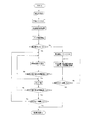
次に、乾燥作業について図1に基づいて説明する。
張込スイッチ21を押すと昇降機5と上部移送装置17と拡散盤18が駆動を開始し、穀粒張込口(図示せず)に張り込まれた穀粒は昇降機5で揚穀され、乾燥室3の穀粒通路11及び貯留室2に順次張り込まれる。
Next, the drying operation will be described with reference to FIG.
When the
張込作業が終了したら張込量設定スイッチ26で張込穀粒量を設定するが、まず、図11に示すように張込穀粒量が最低乾燥張込量以下の場合にLV0.5を張込量設定スイッチ26で設定する。
When the tensioning operation is finished, the tension
乾燥スイッチ23を押すと乾燥作業は開始され、繰り出しバルブ15が穀粒通路11の穀粒を集穀室4に向かって繰り出すと共に、バーナ7の燃焼を開始する。
集穀室4に繰り出された穀粒は穀粒流下板8を流下しながらバーナ7の燃焼で温められた遠赤外線放射体6の放射熱を浴びながら穀粒流下板8を流下して下部移送装置16に供給される。
When the
The grain fed out to the
そして、下部移送装置16で昇降機5に移送され再度貯留室2及び乾燥室11に循環供給される。このとき昇降機5で揚穀されているときに水分計32が所定粒数ずつのサンプル穀粒を設定時間毎に取り込み水分値を演算する。
Then, it is transferred to the
バーナー7は燃焼量を固定にした状態で燃焼を行なう。
すなわち、最低乾燥張込量以下である少量の張込穀粒量で乾燥作業を行なうと穀粒通路11に穀粒が堆積されず、熱風室9a,9bから穀粒通路11に通過した熱風の一部hが穀粒に作用しないで乾燥室3に排出され、熱風室9a,9b近傍に備える熱風温度センサ60に作用することで、熱風温度センサ60の温度検出の精度が低下し、適正な熱風温度センサ60の検出結果に基づくバーナ7の燃焼制御ができなくなってしまう。バーナ7の燃焼量を固定にした状態で燃焼をすることで、安定した燃焼をおこなうことができる。
The
That is, when the drying operation is performed with a small amount of squeezed kernel that is equal to or less than the minimum dry squeezing amount, the kernel is not accumulated in the
この最低乾燥張込量以下の乾燥工程時の燃焼量は所定以下の燃焼量乃至最小燃焼量のいずれかで固定して燃焼するのが良い。すなわち、張込穀粒量が少ないため、燃焼量を抑えることで急激な乾燥による穀粒の胴割れ等の不具合を低減させることができるためである。 It is preferable that the combustion amount at the time of the drying process below the minimum dry filling amount is fixed at any one of the predetermined combustion amount or the minimum combustion amount and burned. That is, since the amount of squeezed kernel is small, it is possible to reduce problems such as cracking of the kernel due to rapid drying by suppressing the amount of combustion.
そして、設定時間(例えば1時間)乾燥工程を行なうと、バーナ7と繰り出しバルブ15を停止して休止工程に入る。この休止工程の間、穀粒内部の水分が順次穀粒表面側に移行して穀粒乾燥を促進することができる。また、この休止工程中は循環しないことで少量の穀粒が多く循環することによる脱ぷ等の穀粒の損傷を低減することができる。
Then, when the drying process is performed for a set time (for example, 1 hour), the
また、休止工程中は吸引ファン12を停止する構成とすることで、遠赤外線放射体6の温度を低下させ難くすることで、休止工程中の穀粒の温度を低下させ難くすることができ、前述の穀粒内部の水分が順次穀粒表面側に移動する水分移行作用を促進することができる。
Moreover, by making it the structure which stops the
休止工程を設定時間(例えば1時間)行なうと再度乾燥工程を再開し、設定水分になるまで乾燥工程と休止工程とが交互に繰り返される。
穀粒が設定水分に到達して乾燥作業を終了してバーナ7を停止した場合は、前述の休止工程とは異なり、バーナ7の停止後吸引ファン12を設定時間(例えば20分)駆動して遠赤外線放射体6の冷却の促進を図る構成としている。
When the pause process is performed for a set time (for example, 1 hour), the drying process is restarted, and the dry process and the pause process are alternately repeated until the set moisture is reached.
When the grain reaches the set moisture and the drying operation is finished and the
次に、通常乾燥張込量(LV1〜LV10)における乾燥作業について説明すると、LV1〜LV10いずれかを張込量設定スイッチ26で設定して乾燥スイッチ23を押すと、バーナ7は乾減率や外気温度センサ34の検出結果や張込穀粒量(LV1〜LV10)等に基づいて燃焼量を制御される。そして、設定水分に到達するまで連続して乾燥工程を行なう。
Next, a description will be given of the drying operation in the normal dry stretch amount (LV1 to LV10). When any of the LV1 to LV10 is set with the stretch
次に、最低乾燥張込量以下の乾燥工程時の水分計32の水分測定について図8に基づいて説明する。
少量の張込穀粒量においても一回の所定粒数(32粒)の水分測定で全ての穀粒の水分を判断するよりも、穀粒層(S1〜S4)毎の水分のバラツキを検出できるのが穀粒の水分状態をより精密に把握することができるため望ましい。
Next, the moisture measurement of the
Rather than judging the moisture of all the grains by measuring the moisture content of a predetermined number of grains (32 grains) at a small amount of stretched grain, the variation in moisture in each grain layer (S1 to S4) is detected. It is desirable to be able to grasp the moisture state of the grain more precisely.
通常の張込穀粒量(LV1〜LV10)の場合には図8の(イ)に示すとおり、32粒ずつ水分計9に取り込む水分測定を、穀粒が乾燥機内を一回循環するまでの時間に設定時間間隔毎に行なう。そして、図8の(イ)の場合には一回循環するまでの時間に4回の水分測定を行なう。そのため、穀粒層(S1〜S4)毎の水分のバラツキ具合を測定することができる。
In the case of normal stretched grain amount (LV1 to LV10), as shown in FIG. 8 (A), the moisture measurement taken into the
なお、一回の循環とは穀粒通路11にある穀粒が集穀室4から下部移送装置16、昇降機5、上部移送装置17の循環工程を経て拡散盤18から貯留室を経て再度穀粒通路11に戻るまでの時間をいう。
In addition, the term “one-time circulation” means that the grains in the
一方、最低乾燥張込量(LV0.5)の場合には一回循環するまでの時間が短いため、図8(ロ)に示すように約130粒の穀粒を連続して水分計32に取り込み水分を測定し、それを後で取り込み順に四回分(一回分約32粒)に分割し、水分値をそれぞれ演算して表示する構成とする。すなわち、所定回数分の水分測定に必要な穀粒の粒数合計を連続して水分計32に取り込み、それを取り込み順に所定回数で所定粒数毎に割って、該所定粒数のそれぞれの水分値を演算・表示するものである。
On the other hand, in the case of the minimum dry filling amount (LV 0.5), since it takes a short time to circulate once, about 130 grains are continuously fed to the
本構成により、少量の張込穀粒量の場合でも穀粒層(S1〜S4)毎の水分のバラツキを検出でき、作業者に有効な穀粒品質情報を提供できる。
なお、ここで記載している穀物層(S1〜S4)とは厳密に層として区別しているのではなく、便宜上おおよその層として認識するものである。
With this configuration, even in the case of a small amount of sown grain, it is possible to detect moisture variation for each grain layer (S1 to S4), and to provide effective grain quality information to the operator.
The grain layers (S1 to S4) described here are not strictly distinguished as layers, but are recognized as approximate layers for convenience.
図7は張込穀粒量を自動に設定できる張込量検出センサ70を備えている場合の乾燥制御である。
張込量検出センサは70は紐70aと紐70aで錘70bを吊り下げる構成で、張り込み作業終了後、錘70bを降ろして張込穀粒の上面に当接したことを検出し、張込穀粒の上面の高さ位置から張込穀粒量を検出する構成である。張込量を検出したら後は図1の流れと同様である。
FIG. 7 shows the drying control in the case where the tension amount detection sensor 70 capable of automatically setting the tension grain amount is provided.
The tension amount detection sensor 70 has a configuration in which the
1 貯留室
7 バーナ
9 熱風室
11 穀粒通路
12 吸引ファン
26 張込穀粒量設定スイッチ
DESCRIPTION OF
Claims (1)
前記穀粒張込量が設定量以下の場合にバーナ(7)の燃焼量を固定に制御し、
バーナ(7)が燃焼する乾燥工程と、バーナ(7)と吸引ファン(12)とが停止する休止工程を、設定水分値に到達するまで設定時間毎に交互に行うことを特徴とする穀粒乾燥機。 A storage chamber (1) for storing the stuck grain, a burner (7) capable of controlling the amount of combustion, a hot air chamber (9) through which hot air generated by the burner (7) passes, and a hot air chamber (9 ) In the grain passage (11) acting on the grain in which the hot air flows down, a suction fan (12) for sucking the hot air that has passed through the grain passage (11), a far-infrared radiator (6), In the grain dryer provided with the tension grain amount setting means (26) for setting the tension grain amount,
When the amount of grain embedding is less than or equal to the set amount, the combustion amount of the burner (7) is fixedly controlled,
A grain characterized by alternately performing a drying process in which the burner (7) burns and a pause process in which the burner (7) and the suction fan (12) stop until the set moisture value is reached. Dryer.
Priority Applications (1)
| Application Number | Priority Date | Filing Date | Title |
|---|---|---|---|
| JP2006324333A JP5011983B2 (en) | 2006-11-30 | 2006-11-30 | Grain dryer |
Applications Claiming Priority (1)
| Application Number | Priority Date | Filing Date | Title |
|---|---|---|---|
| JP2006324333A JP5011983B2 (en) | 2006-11-30 | 2006-11-30 | Grain dryer |
Publications (2)
| Publication Number | Publication Date |
|---|---|
| JP2008138919A JP2008138919A (en) | 2008-06-19 |
| JP5011983B2 true JP5011983B2 (en) | 2012-08-29 |
Family
ID=39600577
Family Applications (1)
| Application Number | Title | Priority Date | Filing Date |
|---|---|---|---|
| JP2006324333A Expired - Fee Related JP5011983B2 (en) | 2006-11-30 | 2006-11-30 | Grain dryer |
Country Status (1)
| Country | Link |
|---|---|
| JP (1) | JP5011983B2 (en) |
Family Cites Families (2)
| Publication number | Priority date | Publication date | Assignee | Title |
|---|---|---|---|---|
| JPS63101689A (en) * | 1986-10-17 | 1988-05-06 | 井関農機株式会社 | Cereal grain drying control system of cereal graing drier |
| JPH0476382A (en) * | 1990-07-13 | 1992-03-11 | Iseki & Co Ltd | Hot air control system for grain dryer |
-
2006
- 2006-11-30 JP JP2006324333A patent/JP5011983B2/en not_active Expired - Fee Related
Also Published As
| Publication number | Publication date |
|---|---|
| JP2008138919A (en) | 2008-06-19 |
Similar Documents
| Publication | Publication Date | Title |
|---|---|---|
| JP2001066065A (en) | Circulative grain drier | |
| JP5293004B2 (en) | Circulating grain dryer | |
| JP2010054148A5 (en) | ||
| JP5011983B2 (en) | Grain dryer | |
| JP2008175415A (en) | Grain drier | |
| JP5391560B2 (en) | Grain dryer | |
| JP2009287870A (en) | Grain dryer | |
| JP2008039221A (en) | Grain drier | |
| JP2015224835A (en) | Crop dryer machine | |
| JP4241367B2 (en) | Grain dryer | |
| JP5125224B2 (en) | Grain dryer | |
| JP3968513B2 (en) | Grain moisture measuring device | |
| JP6244947B2 (en) | Grain dryer | |
| JP4985064B2 (en) | Grain dryer | |
| JP4561777B2 (en) | Far infrared grain dryer | |
| JP2008298324A5 (en) | ||
| JP4325053B2 (en) | Grain dryer burner abnormality determination device | |
| JP4144449B2 (en) | Grain drying equipment | |
| JP6299387B2 (en) | Grain dryer | |
| JP2010127551A (en) | Grain dryer | |
| JP2009085486A (en) | Grain dryer | |
| JP4168571B2 (en) | General-purpose dryer | |
| JP3526465B2 (en) | Display of scheduled drying time of grain dryer | |
| JPH07294125A (en) | Grain temperature detecting device for grain drier | |
| JPH06273039A (en) | Grain drying control method for grain dryer |
Legal Events
| Date | Code | Title | Description |
|---|---|---|---|
| A621 | Written request for application examination |
Free format text: JAPANESE INTERMEDIATE CODE: A621 Effective date: 20091106 |
|
| A131 | Notification of reasons for refusal |
Free format text: JAPANESE INTERMEDIATE CODE: A131 Effective date: 20120214 |
|
| A521 | Written amendment |
Free format text: JAPANESE INTERMEDIATE CODE: A523 Effective date: 20120409 |
|
| TRDD | Decision of grant or rejection written | ||
| A01 | Written decision to grant a patent or to grant a registration (utility model) |
Free format text: JAPANESE INTERMEDIATE CODE: A01 Effective date: 20120508 |
|
| A01 | Written decision to grant a patent or to grant a registration (utility model) |
Free format text: JAPANESE INTERMEDIATE CODE: A01 |
|
| A61 | First payment of annual fees (during grant procedure) |
Free format text: JAPANESE INTERMEDIATE CODE: A61 Effective date: 20120521 |
|
| FPAY | Renewal fee payment (event date is renewal date of database) |
Free format text: PAYMENT UNTIL: 20150615 Year of fee payment: 3 |
|
| R150 | Certificate of patent or registration of utility model |
Ref document number: 5011983 Country of ref document: JP Free format text: JAPANESE INTERMEDIATE CODE: R150 Free format text: JAPANESE INTERMEDIATE CODE: R150 |
|
| LAPS | Cancellation because of no payment of annual fees |