JP4997739B2 - Negative electrode material for lithium ion secondary battery, lithium ion secondary battery using the same, and method for producing lithium ion secondary battery - Google Patents
Negative electrode material for lithium ion secondary battery, lithium ion secondary battery using the same, and method for producing lithium ion secondary battery Download PDFInfo
- Publication number
- JP4997739B2 JP4997739B2 JP2005314699A JP2005314699A JP4997739B2 JP 4997739 B2 JP4997739 B2 JP 4997739B2 JP 2005314699 A JP2005314699 A JP 2005314699A JP 2005314699 A JP2005314699 A JP 2005314699A JP 4997739 B2 JP4997739 B2 JP 4997739B2
- Authority
- JP
- Japan
- Prior art keywords
- negative electrode
- secondary battery
- ion secondary
- lithium ion
- volume
- Prior art date
- Legal status (The legal status is an assumption and is not a legal conclusion. Google has not performed a legal analysis and makes no representation as to the accuracy of the status listed.)
- Expired - Fee Related
Links
Images


Classifications
-
- Y—GENERAL TAGGING OF NEW TECHNOLOGICAL DEVELOPMENTS; GENERAL TAGGING OF CROSS-SECTIONAL TECHNOLOGIES SPANNING OVER SEVERAL SECTIONS OF THE IPC; TECHNICAL SUBJECTS COVERED BY FORMER USPC CROSS-REFERENCE ART COLLECTIONS [XRACs] AND DIGESTS
- Y02—TECHNOLOGIES OR APPLICATIONS FOR MITIGATION OR ADAPTATION AGAINST CLIMATE CHANGE
- Y02E—REDUCTION OF GREENHOUSE GAS [GHG] EMISSIONS, RELATED TO ENERGY GENERATION, TRANSMISSION OR DISTRIBUTION
- Y02E60/00—Enabling technologies; Technologies with a potential or indirect contribution to GHG emissions mitigation
- Y02E60/10—Energy storage using batteries
Landscapes
- Cell Electrode Carriers And Collectors (AREA)
- Secondary Cells (AREA)
- Battery Electrode And Active Subsutance (AREA)
Description
本発明は、構成元素として金属元素および半金属元素のうちの少なくとも1種を含むリチウムイオン二次電池用負極材料およびそれを用いたリチウムイオン二次電池、並びにリチウムイオン二次電池の製造方法に関する。 The present invention relates to a method of manufacturing at least the negative electrode material for a lithium ion secondary battery and a lithium ion secondary battery using the containing one, as well as lithium ion secondary batteries of metal elements and metalloid elements as an element .
近年、モバイル機器の高性能化および多機能化に伴い、それらの電源である二次電池の高容量化が要求されている。この要求に応える二次電池としてはリチウムイオン二次電池があるが、現在実用化されているものは負極に黒鉛を用いているので、電池容量は飽和状態にあり、大幅な高容量化は難しい。そこで、より高容量化を図ることができる負極材料として、ケイ素(Si)あるいはスズ(Sn)またはそれらの合金などを用いることが検討されている(例えば、特許文献1参照。)。
しかしながら、このようにケイ素またはスズを用いた負極材料は、リチウムの吸蔵および放出に伴い体積が大きく変化し、形状が崩壊してしまうので、炭素材料に比べて充放電特性が低く、高容量という特徴を活かすことが難しいという問題があった。 However, the negative electrode material using silicon or tin as described above has a large change in volume with the absorption and release of lithium, and its shape collapses. Therefore, the charge / discharge characteristics are lower than that of the carbon material, and the capacity is high. There was a problem that it was difficult to make use of the features.
本発明はかかる問題点に鑑みてなされたもので、その目的は、膨張収縮による形状崩壊を抑制することができるリチウムイオン二次電池用負極材料およびそれを用いたリチウムイオン二次電池、並びにリチウムイオン二次電池の製造方法を提供することにある。 The present invention has been made in view of the above problems, its object is a lithium-ion secondary battery negative electrode material can be suppressed shape collapse due to expansion and shrinkage, and a lithium ion secondary battery using the same, and lithium It is providing the manufacturing method of an ion secondary battery.
本発明の第1のリチウムイオン二次電池用負極材料は、金属元素および半金属元素のうちの少なくとも1種を構成元素として含み、内部に空隙を有する中空粒子を含有し、中空粒子の平均空隙率は、15体積%以上80体積%以下であり、前記中空粒子の平均粒径は、20μm以下であるものである。 The first negative electrode material for lithium ion secondary battery of the present invention comprises as a constituent element at least one of metal elements and metalloid elements, and contains hollow particles having voids therein, the average void of the hollow particles The rate is 15 volume% or more and 80 volume% or less, and the average particle diameter of the hollow particles is 20 μm or less .
本発明の第2のリチウムイオン二次電池用負極材料は、樹脂よりなる核部に、金属元素および半金属元素のうちの少なくとも1種を構成元素として含む反応部が設けられた複合粒子を含有し、複合粒子における核部の平均体積割合は、15体積%以上80体積%以下であり、複合粒子の平均粒径は、20μm以下であるものである。 The negative electrode material for a second lithium ion secondary battery of the present invention contains composite particles in which a reaction part containing at least one of a metal element and a metalloid element as a constituent element is provided in a core part made of a resin. And the average volume ratio of the core part in a composite particle is 15 volume% or more and 80 volume% or less, and the average particle diameter of a composite particle is 20 micrometers or less .
本発明のリチウムイオン二次電池は、正極および負極と共に電解質を備えたものであって、負極は、金属元素および半金属元素のうちの少なくとも1種を構成元素として含み、内部に空隙を有する中空粒子を含有し、中空粒子の平均空隙率は、15体積%以上80体積%以下であり、中空粒子の平均粒径は、20μm以下であるものである。 The lithium ion secondary battery of the present invention is provided with an electrolyte together with a positive electrode and a negative electrode, and the negative electrode is a hollow having at least one of a metal element and a metalloid element as a constituent element and having voids therein. It contains particles, the average porosity of the hollow particles is 15 volume% or more and 80 volume% or less, and the average particle diameter of the hollow particles is 20 μm or less .
本発明のリチウムイオン二次電池の製造方法は、正極および負極と共に電解質を備えたリチウムイオン二次電池を製造するものであって、樹脂よりなる核部に、金属元素および半金属元素のうちの少なくとも1種を構成元素として含む反応部が設けられ、平均粒径が20μm以下の複合粒子を用いて、成形したのち、核部を除去して平均空隙率が15体積%以上80体積%以下となるように空隙を形成することにより負極を作製する工程を含むものである。 A method for producing a lithium ion secondary battery according to the present invention is a method for producing a lithium ion secondary battery having an electrolyte together with a positive electrode and a negative electrode. A reaction part including at least one kind as a constituent element is provided. After molding using composite particles having an average particle diameter of 20 μm or less , the core part is removed, and the average porosity is 15% by volume or more and 80% by volume or less. Thus, a step of forming a negative electrode by forming a void is included.
本発明の第1のリチウムイオン二次電池用負極材料によれば、内部に空隙を有する中空粒子の空隙率を15体積%以上80体積%以下、中空粒子の平均粒径を20μm以下としたので、空隙により膨張を吸収して、形状の崩壊を抑制することができると共に、負極材料の大きさの変化を小さくすることができる。よって、この負極材料を用いた本発明のリチウムイオン二次電池によれば、高容量を得ることができると共に、優れた充放電特性を得ることができる。 According to the first negative electrode material for a lithium ion secondary battery of the present invention, the void ratio of the hollow particles having voids therein is 15 volume% or more and 80 volume% or less, and the average particle diameter of the hollow particles is 20 μm or less . In addition, the expansion can be absorbed by the voids, the collapse of the shape can be suppressed, and the change in the size of the negative electrode material can be reduced. Therefore, according to the lithium ion secondary battery of the present invention using this negative electrode material, a high capacity can be obtained and excellent charge / discharge characteristics can be obtained.
特に、中空粒子の外側に外層部を設けるようにすれば、中空粒子が外側に膨張することを抑制することができ、より高い効果を得ることができる。 In particular, if the outer layer portion is provided outside the hollow particles, the hollow particles can be prevented from expanding outward, and a higher effect can be obtained.
本発明の第2のリチウムイオン二次電池用負極材料によれば、樹脂よりなる核部に反応部を設けた複合粒子における核部の平均体積割合を15体積%以上80体積%以下、複合粒子の平均粒径を20μm以下になるようにしたので、核部を除去することにより内部に空隙を形成することができる。よって、本発明の第1のリチウムイオン二次電池用負極材料と同様に、空隙により膨張を吸収することができ、形状の崩壊を抑制することができる。 According to the second negative electrode material for a lithium ion secondary battery of the present invention, the average volume ratio of the core part in the composite particle in which the reaction part is provided in the core part made of resin is 15% by volume to 80% by volume, and the composite particle the average particle diameter of the was so that such a 20μm or less, it is possible to form voids therein by removing the core portion. Therefore, like the first negative electrode material for a lithium ion secondary battery of the present invention, the expansion can be absorbed by the voids, and the collapse of the shape can be suppressed.
特に、反応部の外側に外層部を設けるようにすれば、反応部が外側に膨張することを抑制することができ、より高い効果を得ることができる。 In particular, by providing the outer layer on the outside of the reaction section, the reaction section can be suppressed to expand outward, it is possible to obtain a higher effect.
本発明のリチウムイオン二次電池の製造方法によれば、樹脂よりなる核部に反応部を設けた複合粒子を用いて成形したのち核部を除去することにより中空粒子を含有する負極を作製し、その中空粒子の空隙率を15体積%以上80体積%以下、中空粒子の平均粒径を20μm以下にするようにしたので、負極の成形工程において空隙が潰れてしまうことを抑制することができる。よって、本発明のリチウムイオン二次電池を容易に製造することができると共に、より高い効果を得ることができる。 According to the method for producing a lithium ion secondary battery of the present invention, a negative electrode containing hollow particles is prepared by forming a composite particle having a reaction part in a core part made of a resin and then removing the core part. Since the void ratio of the hollow particles is 15% by volume or more and 80% by volume or less and the average particle diameter of the hollow particles is 20 μm or less , the voids can be prevented from being crushed in the negative electrode forming step. . Therefore, the lithium ion secondary battery of the present invention can be easily manufactured and higher effects can be obtained.
以下、本発明の実施の形態について図面を参照して詳細に説明する。 Hereinafter, embodiments of the present invention will be described in detail with reference to the drawings.
図1は本発明の一実施の形態に係る負極材料の構成を表すものである。この負極材料は、樹脂よりなる核部1Aに、電極反応物質を吸蔵および放出可能な反応部1Bが設けられた複合粒子1を含有している。これによりこの負極材料では、核部1Aを除去することにより内部に空隙を形成し、反応部1Bが電極反応物質を吸蔵した際の膨張を吸収することができるようになっている。
FIG. 1 shows a configuration of a negative electrode material according to an embodiment of the present invention. This negative electrode material contains composite particles 1 in which a
核部1Aを構成する樹脂としては、例えば、ポリエチレン樹脂、ポリスチレン樹脂、ポリブタジエン樹脂、ポリプロピレン樹脂、あるいはメタクリル樹脂が挙げられる。
Examples of the resin constituting the
反応部1Bは、金属元素および半金属元素のうちの少なくとも1種を構成元素として含んでいる。例えば電極反応物質がリチウム(Li)である場合には、リチウムと合金を形成可能な金属元素および半金属元素のうちの少なくとも1種を構成元素として含む活物質を含有している。この活物質は、金属元素あるいは半金属元素の単体でも合金でも化合物でもよく、またこれらの1種または2種以上の相を少なくとも一部に有するようなものでもよい。なお、本発明において、合金には2種以上の金属元素からなるものに加えて、1種以上の金属元素と1種以上の半金属元素とを含むものも含める。また、非金属元素を含んでいてもよい。その組織には固溶体,共晶(共融混合物),金属間化合物あるいはそれらのうちの2種以上が共存するものがある。
The
リチウムと合金を形成可能な金属元素あるいは半金属元素としては、例えば、マグネシウム(Mg),ホウ素(B),ヒ素(As),アルミニウム(Al),ガリウム(Ga),インジウム(In),ケイ素,ゲルマニウム(Ge),スズ,鉛(Pb),アンチモン(Sb),ビスマス(Bi),カドミウム(Cd),銀(Ag),亜鉛(Zn),ハフニウム(Hf),ジルコニウム(Zr),イットリウム(Y),パラジウム(Pd)あるいは白金(Pt)が挙げられる。中でも、ケイ素,鉛,スズ,ゲルマニウム,アルミニウムあるいはインジウムが好ましく、より好ましいのは長周期型周期表における14族の金属元素あるいは半金属元素であり、特に好ましいのはケイ素あるいはスズである。より大きな容量を得ることができるからである。
Examples of metal elements or metalloid elements capable of forming an alloy with lithium include magnesium (Mg), boron (B), arsenic (As), aluminum (Al), gallium (Ga), indium (In), silicon, Germanium (Ge), tin, lead (Pb), antimony (Sb), bismuth (Bi), cadmium (Cd), silver (Ag), zinc (Zn), hafnium (Hf), zirconium (Zr), yttrium (Y ), Palladium (Pd) or platinum (Pt). Among these, silicon, lead, tin, germanium, aluminum, or indium is preferable, and a
核部1Aの大きさは、反応部1Bの膨張を十分に吸収することができる大きさであることが好ましい。例えば、反応部1Bをケイ素またはスズにより構成する場合には、リチウムなどの電極反応物質を吸蔵すると約3倍に膨張する。よって、複合粒子1の平均粒径をL1、核部1Aの平均粒径をL2とすると、複合粒子1の平均体積V1は約(1/6)πL13 、核部1Aの平均体積V2は約(1/6)πL23 、反応部1Bの平均体積V3は約(1/6)π(L13 −L23 )であり、反応部1Bの平均増加体積は約(1/3)π(L13 −L23 )である。従って、核部1Aの平均体積V2は反応部1Bの平均増加体積以上、(1/6)πL23 ≧(1/3)π(L13 −L23 )であることが好ましく、すなわち3L23 ≧L13 であることが好ましい。
The size of the
また、複合粒子1における核部1Aの平均体積割合は、15体積%以上80体積%以下であることが好ましい。この割合が小さいと膨張を十分に吸収することができず、大きいと反応部1Bの強度が低下して形状が崩壊しやすくなるからである。複合粒子1における核部1Aの平均体積割合は、例えば、複合粒子1の平均粒径L1と、核部1Aの平均粒径L2とから、核部1Aの平均体積V2/複合粒子1の平均体積V1=[(1/6)πL23 ]/[(1/6)πL13 ]×100(%)、すなわちV2/V1=(L23 /L13 )×100(%)により求められる。
Moreover, it is preferable that the average volume ratio of 1 A of core parts in the composite particle 1 is 15 volume% or more and 80 volume% or less. This is because if the ratio is small, the expansion cannot be sufficiently absorbed, and if the ratio is large, the strength of the
複合粒子1の平均粒径L1は、例えば20μm以下であることが好ましい。あまり大きいと反応部1Bの強度が低下し、形状が崩壊しやすくなるからである。また、複合粒子1の平均粒径L1は、例えば0.5μm以上であればより好ましい。あまり小さいと表面積が増加し、結着量が不足して強度が低下してしまうからである。核部1Aの平均粒径L2は例えば100nm以上であることが好ましく、反応部1Bに粒子状の活物質を用いる場合には、活物質の平均粒径は例えば1μm以下であり、核部1Aの平均粒径L2の10分の1以下であることが好ましい。活物質の平均粒径が大きいと反応部1Bを形成することが難しくなるからである。なお、これらの平均粒径は例えばメディアン径により表される。
The average particle diameter L1 of the composite particles 1 is preferably 20 μm or less, for example. This is because if it is too large, the strength of the
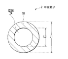
また、この負極材料は、図2に示したように、核部1Aを除去することにより内部に空隙2Aを形成した反応部1Bよりなる中空粒子2を含有していてもよい。核部1Aは完全に除去されていることが好ましいが、一部が残存していてもよい。
In addition, as shown in FIG. 2, the negative electrode material may contain
空隙2Aの大きさは、上述した核部1Aの大きさと同様であり、中空粒子2の平均粒径をL1、空隙2Aの平均径をL2とすると、3L23 ≧L13 であることが好ましい。中空粒子2の平均空隙率は、上述したように15体積%以上80体積%以下であることが好ましい。中空粒子2の平均空隙率は、空隙2Aも含めた中空粒子2の体積に対する空隙2Aの体積の割合であり、例えば、中空粒子2の平均粒径L1と、空隙2Aの平均径L2とから、空隙2Aの平均体積V2/空隙2Aも含めた中空粒子2の平均体積V1=(L23 /L13 )×100(%)により求められる。中空粒子2の平均粒径L1は、上述したように例えば20μm以下であることが好ましく、例えば0.5μm以上であればより好ましい。空隙2Aの平均径L2は、上述したように例えば100nm以上であることが好ましく、反応部1Bに粒子状の活物質を用いる場合には、活物質の平均粒径は例えば1μm以下であり、空隙2Aの平均径L2の10分の1以下であることが好ましい。
The size of the
更に、これら複合粒子1または中空粒子2の外側には、例えば図3(A)(B)に示したように、必要に応じて外層部3が設けられていてもよい。外層部3は、反応部1Bが外側に膨張することを抑制し、空隙2Aの方に選択的に膨張するように促すものである。外層部3は、反応部1Bの全面に設けられていてもよいが、一部に設けられていてもよい。また、外層部3は、電極反応物質が移動できるように空孔を有していてもよい。外層部3は、例えば、コバルト(Co),鉄(Fe),銅(Cu),ニッケル(Ni),マンガン(Mn),チタン(Ti),あるいはニオブ(Nb)の単体および合金のうちの1種以上を含有することが好ましい。これらは、リチウムなどの電極反応物質との反応性が低く、また、高い導電性を有するからである。
Furthermore, the outer layer part 3 may be provided outside the composite particles 1 or the
この負極材料は、次のようにして製造することができる。 This negative electrode material can be manufactured as follows.
まず、例えば、樹脂よりなる核部1Aに、活物質粉末を被着させて反応部1Bを形成する。反応部1Bは、活物質粉末を溶液に懸濁させて核部1Aに噴霧する方法、ボールあるいはビーズなどを用いて衝撃粉砕を行い機械的エネルギーにより付着する方法、メカノケミカル処理により付着させる方法、あるいは超臨界流体を用いたスプレーコーティング法など、どのような方法により形成してもよいが、流動層型造粒法を用いることが好ましい。流動性を高くすることにより、核部1Aの大きさが小さくても、容易に反応部1Bを均一に形成することができるからである。
First, for example, the active material powder is deposited on the
次いで、必要に応じて、反応部1Bに例えば金属粉末を被着させて外層部3を形成する。外層部3は、反応部1Bの形成工程において説明した各種方法により形成することができる。
Next, if necessary, for example, metal powder is deposited on the
続いて、必要に応じて、核部1Aを除去し、内部に空隙2Aを形成する。核部1Aは、例えば、熱処理により溶融除去してもよく、溶媒により溶出除去してもよい。また、核部1Aは、反応部1Bおよび外層部3の形成工程とは別に、使用時に除去するようにしてもよい。これにより負極材料が得られる。
Subsequently, if necessary, the
この負極材料は、例えば次のようにして二次電池に用いられる。なお、以下に示す二次電池では、電極反応物質としてリチウムを用いる場合について説明する。 This negative electrode material is used for a secondary battery as follows, for example. In the secondary battery described below, the case where lithium is used as the electrode reactant will be described.
(第1の電池)
図4は第1の二次電池の構成を表すものである。この二次電池は、いわゆるコイン型といわれるものであり、外装カップ11に収容した負極12と、外装缶13の内に収容した正極14とを、セパレータ15を介して積層したものである。外装カップ11および外装缶13の周縁部は絶縁性のガスケット16を介してかしめることにより密閉されている。外装カップ11および外装缶13は、例えば、ステンレスあるいはアルミニウムなどの金属によりそれぞれ構成されている。
(First battery)
FIG. 4 shows the configuration of the first secondary battery. This secondary battery is a so-called coin-type battery, in which a
負極12は、例えば、負極集電体12Aと、負極集電体12Aに設けられた負極活物質層12Bとを有している。
The
負極集電体12Aは、リチウムと金属間化合物を形成しない金属元素の少なくとも1種を含む金属材料により構成されていることが好ましい。リチウムと金属間化合物を形成すると、充放電に伴い膨張および収縮し、構造破壊が起こって、集電性が低下する他、負極活物質層12Bを支える能力が小さくなるからである。リチウムと金属間化合物を形成しない金属元素としては、例えば、銅,ニッケル,チタン,鉄,コバルトあるいはクロムが挙げられる。 The anode current collector 12A is preferably made of a metal material containing at least one metal element that does not form an intermetallic compound with lithium. This is because when lithium and an intermetallic compound are formed, they expand and contract with charge / discharge, structural destruction occurs, current collection performance decreases, and the ability to support the negative electrode active material layer 12B decreases. Examples of the metal element that does not form an intermetallic compound with lithium include copper, nickel, titanium, iron, cobalt, and chromium.
負極活物質層12Bは、本実施の形態に係る負極材料を含有しており、必要に応じて導電材または結着材を含んでいてもよい。負極材料は、1種を単独で用いてもよいが、組成の異なる2種以上を混合して用いてもよい。負極活物質層22Bは、また、本実施の形態に係る負極材料に加えて他の負極活物質を含んでいてもよい。 The negative electrode active material layer 12B contains the negative electrode material according to the present embodiment, and may contain a conductive material or a binder as necessary. The negative electrode material may be used alone or in combination of two or more different compositions. The negative electrode active material layer 22B may also include other negative electrode active materials in addition to the negative electrode material according to the present embodiment.
正極14は、例えば、正極集電体14Aと、正極集電体14Aに設けられた正極活物質層14Bとを有しており、正極活物質層14Bの側が負極活物質層12Bと対向するように配置されている。正極集電体14Aは、例えば、アルミニウム,ニッケルあるいはステンレスなどにより構成されている。
The
正極活物質層14Bは、例えば、正極活物質としてリチウムを吸蔵および放出することが可能な正極材料のいずれか1種または2種以上を含んでおり、必要に応じて炭素材料などの導電材およびポリフッ化ビニリデンなどの結着材を含んでいてもよい。リチウムを吸蔵および放出することが可能な正極材料としては、例えば、一般式Lix MIO2 で表されるリチウム含有金属複合酸化物が好ましい。リチウム含有金属複合酸化物は、高電圧を発生可能であると共に、高密度であるため、二次電池の更なる高容量化を図ることができるからである。なお、MIは1種類以上の遷移金属であり、例えばコバルトおよびニッケルのうちの少なくとも一方が好ましい。xは電池の充放電状態によって異なり、通常0.05≦x≦1.10の範囲内の値である。このようなリチウム含有金属複合酸化物の具体例としては、LiCoO2 あるいはLiNiO2 などが挙げられる。
The positive electrode
セパレータ15は、負極12と正極14とを隔離し、両極の接触による電流の短絡を防止しつつ、リチウムイオンを通過させるものである。このセパレータ15は、例えば、ポリエチレンやポリプロピレンにより構成されている。
The
セパレータ15には、液状の電解質である電解液が含浸されている。この電解液は、例えば、溶媒と、この溶媒に溶解された電解質塩とを含んでおり、必要に応じて添加剤を含んでいてもよい。溶媒としては、例えば、炭酸エチレン、炭酸プロピレン、炭酸ジメチル、炭酸ジエチル、炭酸エチルメチル、1,3−ジオキソール−2−オン、4−ビニル−1,3−ジオキソラン−2−オン、あるいはハロゲン原子を有する炭酸エステル誘導体などの非水溶媒が挙げられる。溶媒はいずれか1種を単独で用いてもよいが、2種以上を混合して用いてもよい。中でも、1,3−ジオキソール−2−オンおよび4−ビニル−1,3−ジオキソラン−2−オンの少なくとも一方を用いるようにすれば、電解液の分解反応を抑制することができるので好ましい。また、ハロゲン原子を有する炭酸エステル誘導体を用いるようにしても、電解液の分解反応を抑制することができるので好ましい。
The
ハロゲン原子を有する炭酸エステル誘導体は、環式化合物でも鎖式化合物でもよいが、環式化合物の方がより高い効果を得ることができるので好ましい。このような環式化合物としては、4−フルオロ−1,3−ジオキソラン−2−オン、4−クロロ−1,3−ジオキソラン−2−オン、4−ブロモ−1,3−ジオキソラン−2−オン、あるいは4,5−ジフルオロ−1,3−ジオキソラン−2−オンなどが挙げられ、中でも、4−フルオロ−1,3−ジオキソラン−2−オンが好ましい。より高い効果を得ることができるからである。 The carbonic acid ester derivative having a halogen atom may be either a cyclic compound or a chain compound, but the cyclic compound is preferable because a higher effect can be obtained. Such cyclic compounds include 4-fluoro-1,3-dioxolan-2-one, 4-chloro-1,3-dioxolan-2-one, 4-bromo-1,3-dioxolan-2-one Or 4,5-difluoro-1,3-dioxolan-2-one, among which 4-fluoro-1,3-dioxolan-2-one is preferred. This is because a higher effect can be obtained.
電解質塩としては、例えば、LiPF6 ,LiCF3 SO3 あるいはLiClO4 などのリチウム塩が挙げられる。電解質塩は、いずれか1種を単独で用いてもよいが、2種以上を混合して用いてもよい。 Examples of the electrolyte salt include lithium salts such as LiPF 6 , LiCF 3 SO 3, and LiClO 4 . Any one electrolyte salt may be used alone, or two or more electrolyte salts may be mixed and used.
この二次電池は、例えば次のようにして製造することができる。 This secondary battery can be manufactured, for example, as follows.
まず、例えば、本実施の形態に係る負極材料と、必要に応じて導電材または結着材とを混合して負極合剤を調製し、混合溶剤に分散させて負極合剤スラリーを作製する。次いで、この負極合剤スラリーを負極集電体12Aに塗布し、乾燥させたのち加圧成形することにより負極活物質層12Bを形成し、負極12を作製する。その際、負極材料には、図1または図3(A)に示したように、核部1Aを除去する前の複合粒子1を用い、負極活物質層12Bを成形したのちに例えば加熱処理を行うことにより核部1Aを除去し、空隙2Aを形成するようにすることが好ましい。成形時に空隙2Aが潰れてしまうことを抑制することができるからである。
First, for example, the negative electrode material according to the present embodiment is mixed with a conductive material or a binder as necessary to prepare a negative electrode mixture, and dispersed in a mixed solvent to prepare a negative electrode mixture slurry. Next, this negative electrode mixture slurry is applied to the negative electrode current collector 12A, dried, and then subjected to pressure molding to form the negative electrode active material layer 12B, thereby producing the
また、例えば、正極活物質と必要に応じて導電材および結着材とを混合して正極合剤を調製し、混合溶剤に分散させて正極合剤スラリーを作製する。次いで、この正極合剤スラリーを正極集電体14Aに塗布し乾燥させ圧縮して正極活物質層14Bを形成し、正極14を作製する。続いて、負極12、電解液を含浸させたセパレータ15および正極14を積層して、外装カップ11と外装缶13との中に入れ、それらをかしめることにより密閉する。これにより図1に示した二次電池が得られる。
In addition, for example, a positive electrode active material and, if necessary, a conductive material and a binder are mixed to prepare a positive electrode mixture, which is dispersed in a mixed solvent to prepare a positive electrode mixture slurry. Next, the positive electrode mixture slurry is applied to the positive electrode
この二次電池では、充電を行うと、例えば、正極14からリチウムイオンが放出され、電解液を介して負極12に吸蔵される。放電を行うと、例えば、負極12からリチウムイオンが放出され、電解液を介して正極14に吸蔵される。その際、負極12では、リチウムの吸蔵および放出に伴い反応部1Bが膨張収縮するが、空隙2Aによりその体積変化が吸収され、形状の崩壊が抑制される。また、負極材料の大きさの変化が小さくなり、負極活物質層12Bと負極集電体12Aとの接着性が向上する。
In the secondary battery, when charged, for example, lithium ions are released from the
(第2の電池)
図5は第2の二次電池の構成を表すものである。この二次電池は、リード21,22が取り付けられた電極巻回体20をフィルム状の外装部材30の内部に収容したものであり、小型化,軽量化および薄型化が可能となっている。リード21,22は、それぞれ、外装部材30の内部から外部に向かい例えば同一方向に導出されている。リード21,22は、例えば、アルミニウム,銅,ニッケルあるいはステンレスなどの金属材料によりそれぞれ構成されており、それぞれ薄板状または網目状とされている。
(Second battery)
FIG. 5 shows the structure of the second secondary battery. In this secondary battery, the
外装部材30は、例えば、ナイロンフィルム,アルミニウム箔およびポリエチレンフィルムをこの順に貼り合わせた矩形状のアルミラミネートフィルムにより構成されている。外装部材30は、例えば、ポリエチレンフィルム側と電極巻回体20とが対向するように配設されており、各外縁部が融着あるいは接着剤により互いに密着されている。外装部材30とリード21,22との間には、外気の侵入を防止するための密着フィルム31が挿入されている。密着フィルム31は、リード21,22に対して密着性を有する材料、例えば、ポリエチレン,ポリプロピレン,変性ポリエチレンあるいは変性ポリプロピレンなどのポリオレフィン樹脂により構成されている。
The exterior member 30 is made of, for example, a rectangular aluminum laminated film in which a nylon film, an aluminum foil, and a polyethylene film are bonded together in this order. The exterior member 30 is disposed, for example, so that the polyethylene film side and the
なお、外装部材30は、上述したアルミラミネートフィルムに代えて、他の構造を有するラミネートフィルム,ポリプロピレンなどの高分子フィルムあるいは金属フィルムにより構成するようにしてもよい。 The exterior member 30 may be made of a laminated film having another structure, a polymer film such as polypropylene, or a metal film instead of the above-described aluminum laminated film.
図6は図5に示した電極巻回体20のI−I線に沿った断面構造を表すものである。電極巻回体20は、負極23と正極24とをセパレータ25および電解質26を介して積層し、巻回したものであり、最外周部は保護テープ27により保護されている。
FIG. 6 shows a cross-sectional structure taken along line II of the
負極23は、負極集電体23Aの両面に負極活物質層23Bが設けられた構造を有している。正極24も、正極集電体24Aの両面に正極活物質層24Bが設けられた構造を有しており、負極活物質層23Bと正極活物質層24Bとが対向するように配置されている。負極集電体23A,負極活物質層23B,正極集電体24A,正極活物質層24Bおよびセパレータ25の構成は、それぞれ第1の二次電池の負極集電体12A,負極活物質層12B,正極集電体14A,正極活物質層14Bおよびセパレータ15と同様である。
The
電解質層26は、高分子化合物よりなる保持体に電解液を保持させたいわゆるゲル状の電解質により構成されている。ゲル状の電解質は高いイオン伝導率を得ることができると共に、電池の漏液を防止することができるので好ましい。電解液の構成は、第1の二次電池と同様である。高分子材料としては、例えばポリフッ化ビニリデンが挙げられる。
The
この二次電池は、例えば、次のようにして製造することができる。 For example, the secondary battery can be manufactured as follows.
まず、第1の二次電池と同様にして負極23および正極24を作製したのち、負極23および正極24のそれぞれに、高分子化合物に電解液を保持させた電解質層26を形成し、リード21,22を取り付ける。次いで、電解質層26が形成された負極23と正極24とをセパレータ25を介して積層し、巻回して、最外周部に保護テープ27を接着して電極巻回体20を形成する。続いて、例えば、外装部材31の間に電極巻回体20を挟み込み、外装部材31の外縁部同士を熱融着などにより密着させて封入する。その際、リード21,22と外装部材31との間には密着フィルム32を挿入する。これにより、図5,6に示した二次電池が完成する。
First, after making the
また、次のようにして製造してもよい。まず、負極23および正極24を作製し、リード21,22をそれぞれ取り付けたのち、負極23と正極24とをセパレータ25を介して積層して巻回し、最外周部に保護テープ27を接着して、電極巻回体20の前駆体である巻回体を形成する。次いで、この巻回体を外装部材31に挟み、一辺を除く外周縁部を熱融着して袋状としたのち、電解液と、高分子化合物の原料であるモノマーと、重合開始剤と、必要に応じて重合禁止剤などの他の材料とを含む電解質用組成物を、外装部材31の内部に注入する。続いて、外装部材31の開口部を真空雰囲気下で熱融着して密封し、熱を加えてモノマーを重合させて高分子化合物とすることによりゲル状の電解質層26を形成する。これにより、図5,6に示した二次電池が完成する。
Moreover, you may manufacture as follows. First, the
この二次電池の作用は、第1の二次電池と同様である。 The operation of this secondary battery is the same as that of the first secondary battery.
このように本実施の形態によれば、内部に空隙2Aを有する中空粒子2を用いるようにしたので、空隙2Aにより膨張を吸収して、形状の崩壊を抑制することができると共に、負極材料の大きさの変化を小さくすることができる。また、核部1Aに反応部1Bを設けた複合粒子1を用いるようにしたので、核部1Aを除去することにより、内部に空隙2Aを形成し膨張を吸収することができる。よって、負極材料の比表面積の増加に伴う副反応の増大を低減することができると共に、負極活物質層12Bと負極集電体12Aとの接着性を向上させることができる。従って、高容量を得ることができると共に、優れた充放電特性を得ることができる。
As described above, according to the present embodiment, since the
特に、中空粒子2または複合粒子1の外側に外層部3を設けるようにすれば、反応部1Bが外側に膨張することを抑制することができ、より高い効果を得ることができる。
In particular, if the outer layer part 3 is provided outside the
また、中空粒子2の空隙率を15体積%以上80体積%以下の範囲内、または複合粒子1における核部1Aの平均体積割合を15体積%以上80体積%以下の範囲内とするようにすれば、また、中空粒子2または複合粒子1の平均粒径を20μm以下とするようにすれば、より高い効果を得ることができる。
Further, the void ratio of the
更に、負極12,23を、複合粒子1を用いて成形したのちに核部1Aを除去して空隙2Aを形成することにより作製するようにすれば、負極12,23の成形工程において空隙2Aが潰れてしまうことを抑制することができ、より高い効果を得ることができる。
Further, if the
更に、本発明の具体的な実施例について詳細に説明する。 Further, specific embodiments of the present invention will be described in detail.
(実験例1−1〜1−12)
まず、活物質である平均粒径200nmのケイ素粉末と、結着材であるポリフッ化ビニリデンと、分散媒とを混合してスラリー状とし、樹脂よりなる核部1Aに流動層型造粒装置を用いてスプレーコーティングすることにより反応部1Bを形成し、複合粒子1を作製した。その際、実験例1−1〜1−12で、表1に示したように、核部1Aの材料、平均粒径L2、および複合粒子1の平均粒径L1を変化させた。核部1Aの平均粒径L2および複合粒子1の平均粒径L1は、粒度分布測定により得られたメディアン径である。表1に示した空隙率は、核部1Aの平均体積V2/複合粒子1の平均体積V1=(L23 /L13 )×100(%)により求めたものである。
( Experimental Examples 1-1 to 1-12)
First, silicon powder having an average particle diameter of 200 nm as an active material, polyvinylidene fluoride as a binder, and a dispersion medium are mixed to form a slurry, and a fluidized bed granulator is formed on the
なお、実験例1−1〜1−10は核部1Aにメタクリル樹脂を用い、実験例1−11,1−12は核部1Aの材料をポリエチレン樹脂またはポリスチレン樹脂に代えたものである。また、実験例1−1〜1−10は核部1Aの平均粒径を20μm〜2μmの範囲内で変化させると共に、実験例1−1は複合粒子1の平均粒径L1を20μmよりも大きくし、実験例1−2は空隙率を80体積%よりも大きくし、実験例1−3,1−6は空隙率を15体積%よりも小さくしたものである。
Incidentally, the experimental examples 1-1 to 1-10 is used methacrylic
次いで、作製した複合粒子1に、メカノケミカル法により平均粒径100nmの銅粉末を被着させ、外層部3を形成した。これにより実験例1−1〜1−12の負極材料を得た。作製した負極材料について、集束イオンビーム(FIB;Focused Ion Beam)により断面を出し、走査電子顕微鏡(Scanning Electron Microscope;SEM)により断面を観察したところ、核部1Aの周りに反応部1Bが形成され、その外側に外層部3が形成されていることが確認された。
Next, copper powder having an average particle diameter of 100 nm was deposited on the produced composite particle 1 by a mechanochemical method, thereby forming the outer layer portion 3. This obtained the negative electrode material of Experimental example 1-1 to 1-12. About the produced negative electrode material, when a cross section was taken out by focused ion beam (FIB) and the cross section was observed with a scanning electron microscope (SEM), a
続いて、作製した負極材料を用い、図4に示したようなコイン型の二次電池を作製した。負極12は、作製した負極材料と、結着材であるポリフッ化ビニリデンとを、分散媒を用いて混合し、厚み12μmの粗面化した銅箔よりなる負極集電体12Aに塗布・乾燥したのち、加圧成形し、真空雰囲気中において500℃で12時間の熱処理を行って負極活物質層12Bを形成することにより作製した。
Subsequently, a coin-type secondary battery as shown in FIG. 4 was produced using the produced negative electrode material. The
正極14は、正極活物質であるコバルト酸リチウム(LiCoO2 )粉末と、導電材であるカーボンブラックと、結着材であるポリフッ化ビニリデンと、分散媒とを混合し、アルミニウム箔よりなる正極集電体14Aに塗布・乾燥したのち、加圧成形して正極活物質層14Bを形成することにより作製した。セパレータ15にはポリプロピレン製の多孔質フィルムを用い、電解液には4−フルオロ−1,3−ジオキソラン−2−オン50質量%と炭酸ジエチル50質量%とを混合した溶媒にLiPF6 を1mol/kg溶解させたものを用いた。
The
また、実験例1−1〜1−12に対する比較例1−1として、平均粒径10μmのケイ素粉末を負極材料として用いたことを除き、他は本実験例と同様にして二次電池を作製した。比較例1−2として、平均粒径10μmのケイ素粉末に平均粒径100nmの銅粉末をメカノケミカル法により被着させたものを負極材料として用いたことを除き、他は本実験例と同様にして二次電池を作製した。 Further, as Comparative Example 1-1 with respect to Experimental Examples 1-1 to 1-12, a secondary battery was fabricated in the same manner as in this Experimental Example, except that silicon powder having an average particle diameter of 10 μm was used as the negative electrode material. did. Comparative Example 1-2 was the same as in this experimental example, except that a silicon powder having an average particle size of 10 μm and a copper powder having an average particle size of 100 nm deposited by mechanochemical method was used as the negative electrode material. A secondary battery was manufactured.
作製した実験例および比較例の二次電池について充放電試験を行い、放電容量維持率を求めた。その際、充電は、電流密度1mA/cm2 、上限電圧4.2Vの条件で定電流定電圧充電を行い、放電は、電流密度1mA/cm2 、終止電圧2.5Vの条件で定電流放電を行った。放電容量維持率は1サイクル目の放電容量に対する20サイクル目の放電容量の比率を百分率として算出した。得られた結果を表1に示す。 A charge / discharge test was performed on the fabricated secondary batteries of the experimental example and the comparative example, and the discharge capacity retention rate was obtained. At that time, charging is constant current and constant voltage charging under conditions of current density of 1 mA / cm 2 and upper limit voltage of 4.2 V, and discharging is constant current discharging under conditions of current density of 1 mA / cm 2 and final voltage of 2.5 V. Went. The discharge capacity retention ratio was calculated by using the ratio of the discharge capacity at the 20th cycle to the discharge capacity at the 1st cycle as a percentage. The obtained results are shown in Table 1.

表1に示したように、空隙2Aを形成した実験例1−1〜1−12によれば、空隙を形成していない比較例1−1,1−2に比べて、放電容量維持率を向上させることができた。すなわち、中空粒子2を用いるようにすれば、サイクル特性を向上させることができることが分かった。
As shown in Table 1, according to Experimental Examples 1-1 to 1-12 in which the
また、中空粒子2の平均粒径L1についてみると、平均粒径L1を20μmよりも大きくした実験例1−1に比べて、20μm以下とした実験例1−2〜1−12の方が、放電容量維持率をより向上させることができた。更に、中空粒子2の空隙率についてみると、空隙率を80体積%よりも大きくした実験例1−2、および空隙率を15体積%よりも小さくした実験例1−3,1−6に比べて、15体積%以上80体積%以下の範囲内とした実験例1−4,1−5,1−7〜1−10の方が、放電容量維持率をより向上させることができた。図7に、実験例1−2〜1−10の空隙率と放電容量維持率との関係を示す。
Moreover, when it sees about the average particle diameter L1 of the
すなわち、中空粒子2または複合粒子1の平均粒径L1を20μm以下とするようにすれば、また、中空粒子2の空隙率または複合粒子1における核部1Aの平均体積割合を15体積%以上80体積%以下とするようにすれば、より高い効果を得られることが分かった。
That is, if the average particle diameter L1 of the
(実験例2−1,2−2)
活物質であるケイ素粉末の平均粒径を2000nmまたは100nmとしたことを除き、他は実験例1−4と同様にして負極材料および二次電池を作製した。実験例2−1,2−2についても、実験例1−4と同様にして、平均粒径L1および空隙率を求めた。また、実験例1−4と同様にして、二次電池について充放電を行い、放電容量維持率を求めた。得られた結果を実験例1−4の結果と共に表2に示す。
( Experimental examples 2-1 and 2-2)
A negative electrode material and a secondary battery were produced in the same manner as in Experimental Example 1-4, except that the average particle size of the silicon powder as the active material was 2000 nm or 100 nm. For Experimental Examples 2-1 and 2-2, the average particle diameter L1 and the porosity were determined in the same manner as in Experimental Example 1-4. Moreover, it charged / discharged about the secondary battery similarly to Experimental example 1-4, and calculated | required the discharge capacity maintenance factor. The obtained results are shown in Table 2 together with the results of Experimental Example 1-4.
表2に示したように、活物質の平均粒径を2000nmと大きくした実験例2−1に比べて、それよりも小さくした実験例1−4,2−2の方が、より高い放電容量維持率を得ることができた。すなわち、活物質の平均粒径を1μm以下、または核部1Aの平均粒径L2の10分の1以下とすれば、より高い効果を得られることが分かった。
As shown in Table 2, compared to Experimental Example 2-1, in which the average particle size of the active material was increased to 2000 nm, Experimental Examples 1-4 and 2-2 having a smaller average particle size had a higher discharge capacity. A maintenance rate was obtained. That is, it has been found that a higher effect can be obtained if the average particle size of the active material is 1 μm or less, or 1/10 or less of the average particle size L2 of the
(実験例3−1)
外層部3を形成せずに複合粒子1をそのまま負極材料として用いたことを除き、他は実験例1−10と同様にして負極材料および二次電池を作製した。また、実験例3−1に対する比較例3−1として、平均粒径2.8μmのケイ素粉末をそのまま負極材料として用いたことを除き、他は実験例1−10と同様にして二次電池を作製した。実験例3−1および比較例3−1についても、実験例1−10と同様にして充放電を行い、放電容量維持率を求めた。得られた結果を実験例1−10の結果と共に表3に示す。
( Experimental example 3-1)
A negative electrode material and a secondary battery were produced in the same manner as in Experimental Example 1-10 except that the composite particle 1 was used as it was as the negative electrode material without forming the outer layer portion 3. Further, as Comparative Example 3-1, compared to Experimental Example 3-1, a secondary battery was manufactured in the same manner as Experimental Example 1-10 except that silicon powder having an average particle size of 2.8 μm was used as it was as a negative electrode material. Produced. For Experimental Example 3-1 and Comparative Example 3-1, charging and discharging were performed in the same manner as in Experimental Example 1-10, and the discharge capacity retention rate was obtained. The obtained results are shown in Table 3 together with the results of Experimental Example 1-10.
表3に示したように、外層部3を形成していない実験例3−1についても、実験例1−1〜1−12と同様に、空隙を形成していない比較例3−1に比べて放電容量維持率を向上させることができた。但し、外層部3を形成した実験例1−10の方が、より高い放電容量維持率を得ることができた。すなわち、外層部3を形成するようにすればより高い効果を得られることが分かった。 As shown in Table 3, the experimental example 3-1 in which the outer layer portion 3 is not formed is also similar to the comparative example 3-1 in which no gap is formed, as in the experimental examples 1-1 to 1-12. As a result, the discharge capacity retention rate could be improved. However, Experimental Example 1-10 in which the outer layer part 3 was formed was able to obtain a higher discharge capacity retention rate. That is, it has been found that if the outer layer portion 3 is formed, a higher effect can be obtained.
(実験例4−1〜4−8)
活物質としてスズ粉末を用いたことを除き、他は実験例1−1〜1−10と同様にして負極材料および二次電池を作製した。その際、実験例4−1〜4−8で、表4に示したように、核部1Aの材料、平均粒径L2、スズ粉末の平均粒径、および複合粒子1の平均粒径L1を変化させた。実験例4−1〜4−8についても、実験例1−1〜1−10と同様にして、平均粒径L2,L1および空隙率を求めた。また、実験例4−1〜4−8に対する比較例4−1として、平均粒径14μmのスズ粉末を負極材料として用いたことを除き、他は本実験例と同様にして二次電池を作製した。作製した実験例4−1〜4−8の二次電池についても、実験例1−1〜1−12と同様にして充放電を行い、放電容量維持率を求めた。得られた結果を表4に示す。
( Experimental examples 4-1 to 4-8)
A negative electrode material and a secondary battery were produced in the same manner as in Experimental Examples 1-1 to 1-10, except that tin powder was used as the active material. At that time, as shown in Table 4 in Experimental Examples 4-1 to 4-8, the material of the
表4に示したように、実験例4−1〜4−8についても、実験例1−1〜1−12と同様に、比較例4−1に比べて放電容量維持率を向上させることができた。また、中空粒子2の平均粒径L1を20μm以下、中空粒子2の空隙率を15体積%以上80体積%以下、活物質の平均粒径を1μm以下とした実験例4−4〜4−7によれば、より高い放電容量維持率を得ることができた。すなわち、リチウムと合金を形成可能な金属元素または半金属元素を含む他の活物質を用いても、同様の効果を得られることが分かった。
As shown in Table 4, also in Experimental Examples 4-1 to 4-8, the discharge capacity retention rate can be improved as compared with Comparative Example 4-1, similarly to Experimental Examples 1-1 to 1-12. did it. Experimental Examples 4-4 to 4-7, in which the average particle diameter L1 of the
以上、実施の形態および実施例を挙げて本発明を説明したが、本発明は実施の形態および実施例に限定されず、種々の変形が可能である。例えば、上記実施の形態および実施例では、液状の電解質である電解液、またはいわゆるゲル状の電解質を用いる場合について説明したが、他の電解質を用いるようにしてもよい。他の電解質としては、イオン伝導性を有する固体電解質、固体電解質と電解液とを混合したもの、あるいは固体電解質とゲル状の電解質とを混合したものが挙げられる。 Although the present invention has been described with reference to the embodiments and examples, the present invention is not limited to the embodiments and examples, and various modifications can be made. For example, in the above-described embodiments and examples, the case where an electrolytic solution which is a liquid electrolyte or a so-called gel electrolyte is used has been described, but another electrolyte may be used. Examples of other electrolytes include solid electrolytes having ionic conductivity, a mixture of a solid electrolyte and an electrolyte solution, and a mixture of a solid electrolyte and a gel electrolyte.
なお、固体電解質には、例えば、イオン伝導性を有する高分子化合物に電解質塩を分散させた高分子固体電解質、またはイオン伝導性ガラスあるいはイオン性結晶などよりなる無機固体電解質を用いることができる。高分子固体電解質の高分子化合物としては、例えば、ポリエチレンオキサイドあるいはポリエチレンオキサイドを含む架橋体などのエーテル系高分子化合物、ポリメタクリレートなどのエステル系高分子化合物、アクリレート系高分子化合物を単独あるいは混合して、または共重合させて用いることができる。また、無機固体電解質としては、窒化リチウムあるいはリン酸リチウムなどを含むもの用いることができる。 As the solid electrolyte, for example, a polymer solid electrolyte in which an electrolyte salt is dispersed in a polymer compound having ion conductivity, or an inorganic solid electrolyte made of ion conductive glass or ionic crystals can be used. Examples of the polymer compound of the solid polymer electrolyte include, for example, an ether polymer compound such as polyethylene oxide or a crosslinked product containing polyethylene oxide, an ester polymer compound such as polymethacrylate, and an acrylate polymer compound. Or can be copolymerized. In addition, as the inorganic solid electrolyte, one containing lithium nitride or lithium phosphate can be used.
また、上記実施の形態および実施例では、コイン型および巻回ラミネート型の二次電池について説明したが、本発明は、円筒型,角型,ボタン型,薄型,大型あるいは積層ラミネート型などの他の形状を有する二次電池についても同様に適用することができる。 In the above embodiments and examples, the coin type and wound laminate type secondary batteries have been described. However, the present invention is not limited to a cylindrical type, a square type, a button type, a thin type, a large size, or a laminated laminate type. secondary batteries having the shape Ru can be applied similarly.
1…複合粒子、1A…核部、1B…反応部、2…中空粒子、2A…空隙、3…外層部、11…外装カップ、12,23…負極、12A,23A…負極集電体、12B,23B…負極活物質層、13…外装缶、14,24…正極、14A,24A…正極集電体、14B,24B…正極活物質層、15,25…セパレータ、16…ガスケット、20…電極巻回体、21,22…リード、26…電解質層、27…保護テープ、30…外装部材、31…密着フィルム
DESCRIPTION OF SYMBOLS 1 ... Composite particle | grains, 1A ... Core part, 1B ... Reaction part, 2 ... Hollow particle, 2A ... Space | gap, 3 ... Outer layer part, 11 ... Exterior cup, 12, 23 ... Negative electrode, 12A, 23A ... Negative electrode collector, 12B , 23B ... negative electrode active material layer, 13 ... outer can, 14, 24 ... positive electrode, 14A, 24A ... positive electrode current collector, 14B, 24B ... positive electrode active material layer, 15, 25 ... separator, 16 ... gasket, 20 ... electrode Winding body, 21, 22 ... lead, 26 ... electrolyte layer, 27 ... protective tape, 30 ... exterior member, 31 ... adhesion film
Claims (15)
前記中空粒子の平均空隙率は、15体積%以上80体積%以下であり、前記中空粒子の平均粒径は、20μm以下である、リチウムイオン二次電池用負極材料。 Containing at least one of a metal element and a metalloid element as a constituent element, containing hollow particles having voids inside ,
The average porosity of the hollow particles is 15 volume% or more and 80 volume% or less, and the average particle diameter of the hollow particles is 20 μm or less .
前記複合粒子における前記核部の平均体積割合は、15体積%以上80体積%以下であり、前記複合粒子の平均粒径は、20μm以下である、リチウムイオン二次電池用負極材料。 Containing a composite particle in which a reaction part including at least one of a metal element and a metalloid element as a constituent element is provided in a core part made of a resin ;
The negative electrode material for a lithium ion secondary battery, wherein an average volume ratio of the core in the composite particles is 15% by volume to 80% by volume, and an average particle diameter of the composite particles is 20 μm or less .
前記中空粒子の平均空隙率は、15体積%以上80体積%以下であり、前記中空粒子の平均粒径は、20μm以下である、リチウムイオン二次電池。 Provided with an electrolyte together with a positive electrode and a negative electrode, the negative electrode contains at least one of a metal element and a metalloid element as a constituent element, contains hollow particles having voids inside ,
The average porosity of the hollow particles is 15 volume% or more and 80 volume% or less, and the average particle diameter of the hollow particles is 20 μm or less .
樹脂よりなる核部に、金属元素および半金属元素のうちの少なくとも1種を構成元素として含む反応部が設けられ、平均粒径が20μm以下の複合粒子を用いて、成形したのち、前記核部を除去して平均空隙率が15体積%以上80体積%以下となるように空隙を形成することにより負極を作製する工程を含む、リチウムイオン二次電池の製造方法。 A method for producing a lithium ion secondary battery comprising an electrolyte together with a positive electrode and a negative electrode,
A reaction part including at least one of a metal element and a metalloid element as a constituent element is provided in a core part made of a resin, and the core part is molded using composite particles having an average particle size of 20 μm or less. The manufacturing method of a lithium ion secondary battery including the process of producing a negative electrode by forming a space | gap so that an average porosity may be 15 volume% or more and 80 volume% or less by removing.
Priority Applications (1)
| Application Number | Priority Date | Filing Date | Title |
|---|---|---|---|
| JP2005314699A JP4997739B2 (en) | 2005-10-28 | 2005-10-28 | Negative electrode material for lithium ion secondary battery, lithium ion secondary battery using the same, and method for producing lithium ion secondary battery |
Applications Claiming Priority (1)
| Application Number | Priority Date | Filing Date | Title |
|---|---|---|---|
| JP2005314699A JP4997739B2 (en) | 2005-10-28 | 2005-10-28 | Negative electrode material for lithium ion secondary battery, lithium ion secondary battery using the same, and method for producing lithium ion secondary battery |
Publications (3)
| Publication Number | Publication Date |
|---|---|
| JP2007123100A JP2007123100A (en) | 2007-05-17 |
| JP2007123100A5 JP2007123100A5 (en) | 2008-11-13 |
| JP4997739B2 true JP4997739B2 (en) | 2012-08-08 |
Family
ID=38146712
Family Applications (1)
| Application Number | Title | Priority Date | Filing Date |
|---|---|---|---|
| JP2005314699A Expired - Fee Related JP4997739B2 (en) | 2005-10-28 | 2005-10-28 | Negative electrode material for lithium ion secondary battery, lithium ion secondary battery using the same, and method for producing lithium ion secondary battery |
Country Status (1)
| Country | Link |
|---|---|
| JP (1) | JP4997739B2 (en) |
Families Citing this family (15)
| Publication number | Priority date | Publication date | Assignee | Title |
|---|---|---|---|---|
| EP2139009B1 (en) * | 2007-04-13 | 2013-06-26 | Sekisui Chemical Co., Ltd. | Electroconductive fine particles, anisotropic electroconductive material, and electroconductive connection structure |
| KR20110135858A (en) * | 2009-02-27 | 2011-12-19 | 제온 코포레이션 | Negative electrode active material for lithium ion secondary battery, and lithium ion secondary battery |
| US20100285358A1 (en) | 2009-05-07 | 2010-11-11 | Amprius, Inc. | Electrode Including Nanostructures for Rechargeable Cells |
| US8450012B2 (en) | 2009-05-27 | 2013-05-28 | Amprius, Inc. | Interconnected hollow nanostructures containing high capacity active materials for use in rechargeable batteries |
| US9780365B2 (en) | 2010-03-03 | 2017-10-03 | Amprius, Inc. | High-capacity electrodes with active material coatings on multilayered nanostructured templates |
| US9172088B2 (en) | 2010-05-24 | 2015-10-27 | Amprius, Inc. | Multidimensional electrochemically active structures for battery electrodes |
| JP5271967B2 (en) | 2010-05-28 | 2013-08-21 | 株式会社日立製作所 | Negative electrode for non-aqueous secondary battery and non-aqueous secondary battery |
| JP2012069427A (en) * | 2010-09-24 | 2012-04-05 | Toshiba Corp | Active material and secondary battery |
| WO2012067943A1 (en) | 2010-11-15 | 2012-05-24 | Amprius, Inc. | Electrolytes for rechargeable batteries |
| KR101687055B1 (en) | 2013-05-16 | 2016-12-15 | 주식회사 엘지화학 | Hollow silicon-based particles, preparation method of thereof, and anode active material for lithium secondary battery comprising the same |
| WO2014207921A1 (en) * | 2013-06-28 | 2014-12-31 | 株式会社日立製作所 | Negative-electrode active substance, method for manufacturing same, and lithium-ion secondary cell |
| JP2015040150A (en) * | 2013-08-22 | 2015-03-02 | Jnc株式会社 | Method for producing almost spherical silicon powder, and almost spherical silicon powder |
| KR102535137B1 (en) | 2014-05-12 | 2023-05-22 | 암프리우스, 인코포레이티드 | Structurally controlled deposition of silicon onto nanowires |
| CN105406050B (en) * | 2015-12-31 | 2018-11-02 | 深圳市贝特瑞新能源材料股份有限公司 | A kind of comprehensive silicon negative material, preparation method and purposes |
| JP7061740B2 (en) * | 2018-07-30 | 2022-05-02 | 国立大学法人三重大学 | Fertilized egg retention structure and fertilized egg inspection method using it |
Family Cites Families (6)
| Publication number | Priority date | Publication date | Assignee | Title |
|---|---|---|---|---|
| JPS59228359A (en) * | 1983-06-09 | 1984-12-21 | Matsushita Electric Ind Co Ltd | Active metal substance for negative electrode of battery |
| JPS6056367A (en) * | 1983-09-07 | 1985-04-01 | Hitachi Maxell Ltd | Alkaline battery |
| JPH01122564A (en) * | 1987-11-07 | 1989-05-15 | Yuasa Battery Co Ltd | Sealed type lead-acid battery |
| JP3977354B2 (en) * | 1995-03-17 | 2007-09-19 | キヤノン株式会社 | Method for producing positive electrode active material, method for producing negative electrode active material, and method for producing secondary battery using lithium |
| JP4171904B2 (en) * | 2003-08-05 | 2008-10-29 | 信越化学工業株式会社 | Lithium ion secondary battery negative electrode material and method for producing the same |
| JP2005071655A (en) * | 2003-08-28 | 2005-03-17 | Mitsubishi Materials Corp | Anode material for nonaqueous electrolytic solution secondary battery, its manufacturing method, and nonaqueous electrolytic solution secondary battery using same |
-
2005
- 2005-10-28 JP JP2005314699A patent/JP4997739B2/en not_active Expired - Fee Related
Also Published As
| Publication number | Publication date |
|---|---|
| JP2007123100A (en) | 2007-05-17 |
Similar Documents
| Publication | Publication Date | Title |
|---|---|---|
| JP4997739B2 (en) | Negative electrode material for lithium ion secondary battery, lithium ion secondary battery using the same, and method for producing lithium ion secondary battery | |
| US8956758B2 (en) | Anode active material and battery | |
| JP5364230B2 (en) | Negative electrode and battery | |
| JP4622803B2 (en) | Negative electrode for lithium ion secondary battery, lithium ion secondary battery, and production method thereof | |
| JP5338041B2 (en) | Negative electrode for secondary battery and secondary battery | |
| JP5076316B2 (en) | Negative electrode for secondary battery and secondary battery | |
| JP4609048B2 (en) | Negative electrode for secondary battery and secondary battery | |
| KR101829528B1 (en) | Electrode, nonaqueous electrolyte battery and battery pack | |
| JP2007305424A (en) | Negative electrode active material, and battery using it | |
| JP5827103B2 (en) | Small non-aqueous electrolyte secondary battery and manufacturing method thereof | |
| JP3546798B2 (en) | Non-aqueous electrolyte secondary battery, alloy for the battery, and method of manufacturing the same | |
| JP2004185862A (en) | Lithium ion secondary battery and its manufacturing method | |
| JP2006216374A (en) | Negative electrode material and battery using it | |
| US9660254B2 (en) | Method for producing silicon-based negative electrode active material, negative electrode active material for lithium secondary battery, and lithium secondary battery comprising same | |
| KR101551682B1 (en) | Electrode and method of manufacturing an active material for the electrode | |
| JP5098144B2 (en) | Negative electrode and battery | |
| KR102586846B1 (en) | Lithium secondary battery | |
| KR101190026B1 (en) | Negative electrode material and battery using the same | |
| JP4877475B2 (en) | Negative electrode and battery | |
| JP6076802B2 (en) | Method for producing negative electrode for lithium ion secondary battery | |
| JP6583993B2 (en) | Lithium secondary battery charge / discharge method | |
| JP2001291513A (en) | Manufacturing method of negative electrode material for nonaqueous electrolyte secondary battery | |
| US9263742B2 (en) | Negative electrode active substance for lithium secondary battery and method for producing same | |
| JP2001148247A (en) | Non-aqueous electrolyte secondary battery and alloy for battery and its manufacturing method | |
| JP6818300B2 (en) | Lithium secondary battery charging / discharging method |
Legal Events
| Date | Code | Title | Description |
|---|---|---|---|
| A521 | Written amendment |
Free format text: JAPANESE INTERMEDIATE CODE: A523 Effective date: 20080926 |
|
| A621 | Written request for application examination |
Free format text: JAPANESE INTERMEDIATE CODE: A621 Effective date: 20080926 |
|
| A977 | Report on retrieval |
Free format text: JAPANESE INTERMEDIATE CODE: A971007 Effective date: 20110819 |
|
| A131 | Notification of reasons for refusal |
Free format text: JAPANESE INTERMEDIATE CODE: A131 Effective date: 20110927 |
|
| A521 | Written amendment |
Free format text: JAPANESE INTERMEDIATE CODE: A523 Effective date: 20111122 |
|
| TRDD | Decision of grant or rejection written | ||
| A01 | Written decision to grant a patent or to grant a registration (utility model) |
Free format text: JAPANESE INTERMEDIATE CODE: A01 Effective date: 20120417 |
|
| A01 | Written decision to grant a patent or to grant a registration (utility model) |
Free format text: JAPANESE INTERMEDIATE CODE: A01 |
|
| A61 | First payment of annual fees (during grant procedure) |
Free format text: JAPANESE INTERMEDIATE CODE: A61 Effective date: 20120430 |
|
| FPAY | Renewal fee payment (event date is renewal date of database) |
Free format text: PAYMENT UNTIL: 20150525 Year of fee payment: 3 |
|
| LAPS | Cancellation because of no payment of annual fees |