JP4991663B2 - Steam turbine blade assembly - Google Patents
Steam turbine blade assembly Download PDFInfo
- Publication number
- JP4991663B2 JP4991663B2 JP2008231617A JP2008231617A JP4991663B2 JP 4991663 B2 JP4991663 B2 JP 4991663B2 JP 2008231617 A JP2008231617 A JP 2008231617A JP 2008231617 A JP2008231617 A JP 2008231617A JP 4991663 B2 JP4991663 B2 JP 4991663B2
- Authority
- JP
- Japan
- Prior art keywords
- blade
- shroud
- hole
- rod
- shaped member
- Prior art date
- Legal status (The legal status is an assumption and is not a legal conclusion. Google has not performed a legal analysis and makes no representation as to the accuracy of the status listed.)
- Expired - Fee Related
Links
Images
Classifications
-
- F—MECHANICAL ENGINEERING; LIGHTING; HEATING; WEAPONS; BLASTING
- F01—MACHINES OR ENGINES IN GENERAL; ENGINE PLANTS IN GENERAL; STEAM ENGINES
- F01D—NON-POSITIVE DISPLACEMENT MACHINES OR ENGINES, e.g. STEAM TURBINES
- F01D5/00—Blades; Blade-carrying members; Heating, heat-insulating, cooling or antivibration means on the blades or the members
- F01D5/12—Blades
- F01D5/22—Blade-to-blade connections, e.g. for damping vibrations
- F01D5/225—Blade-to-blade connections, e.g. for damping vibrations by shrouding
-
- F—MECHANICAL ENGINEERING; LIGHTING; HEATING; WEAPONS; BLASTING
- F01—MACHINES OR ENGINES IN GENERAL; ENGINE PLANTS IN GENERAL; STEAM ENGINES
- F01D—NON-POSITIVE DISPLACEMENT MACHINES OR ENGINES, e.g. STEAM TURBINES
- F01D5/00—Blades; Blade-carrying members; Heating, heat-insulating, cooling or antivibration means on the blades or the members
- F01D5/12—Blades
- F01D5/22—Blade-to-blade connections, e.g. for damping vibrations
-
- F—MECHANICAL ENGINEERING; LIGHTING; HEATING; WEAPONS; BLASTING
- F01—MACHINES OR ENGINES IN GENERAL; ENGINE PLANTS IN GENERAL; STEAM ENGINES
- F01D—NON-POSITIVE DISPLACEMENT MACHINES OR ENGINES, e.g. STEAM TURBINES
- F01D11/00—Preventing or minimising internal leakage of working-fluid, e.g. between stages
- F01D11/005—Sealing means between non relatively rotating elements
- F01D11/006—Sealing the gap between rotor blades or blades and rotor
-
- F—MECHANICAL ENGINEERING; LIGHTING; HEATING; WEAPONS; BLASTING
- F01—MACHINES OR ENGINES IN GENERAL; ENGINE PLANTS IN GENERAL; STEAM ENGINES
- F01D—NON-POSITIVE DISPLACEMENT MACHINES OR ENGINES, e.g. STEAM TURBINES
- F01D25/00—Component parts, details, or accessories, not provided for in, or of interest apart from, other groups
- F01D25/04—Antivibration arrangements
- F01D25/06—Antivibration arrangements for preventing blade vibration
-
- F—MECHANICAL ENGINEERING; LIGHTING; HEATING; WEAPONS; BLASTING
- F01—MACHINES OR ENGINES IN GENERAL; ENGINE PLANTS IN GENERAL; STEAM ENGINES
- F01D—NON-POSITIVE DISPLACEMENT MACHINES OR ENGINES, e.g. STEAM TURBINES
- F01D5/00—Blades; Blade-carrying members; Heating, heat-insulating, cooling or antivibration means on the blades or the members
- F01D5/12—Blades
- F01D5/26—Antivibration means not restricted to blade form or construction or to blade-to-blade connections or to the use of particular materials
-
- F—MECHANICAL ENGINEERING; LIGHTING; HEATING; WEAPONS; BLASTING
- F05—INDEXING SCHEMES RELATING TO ENGINES OR PUMPS IN VARIOUS SUBCLASSES OF CLASSES F01-F04
- F05D—INDEXING SCHEME FOR ASPECTS RELATING TO NON-POSITIVE-DISPLACEMENT MACHINES OR ENGINES, GAS-TURBINES OR JET-PROPULSION PLANTS
- F05D2220/00—Application
- F05D2220/30—Application in turbines
- F05D2220/31—Application in turbines in steam turbines
Landscapes
- Engineering & Computer Science (AREA)
- Mechanical Engineering (AREA)
- General Engineering & Computer Science (AREA)
- Turbine Rotor Nozzle Sealing (AREA)
Description
本発明は、蒸気タービン動翼及びそれを用いた組立体に関する。 The present invention relates to a steam turbine blade and an assembly using the same.
蒸気タービン動翼は、ロータの回転に伴って大きな遠心力が作用し、かつ、蒸気による振動荷重が作用するため、構造、特に、翼の植え込み部と翼の先端部のシュラウドにはさまざまな工夫がなされている。 Steam turbine rotor blades are subject to a large centrifugal force as the rotor rotates and vibration loads due to steam. Therefore, there are various ingenuity in the structure, especially the shroud at the blade implant and the blade tip. Has been made.
すなわち、蒸気振動荷重による応答応力を低減するために、翼の先端に隣接する翼同志が接触するインテグラルシュラウド構造が提案されている。また、インテグラルシュラウドの隣接面に接続板やピンを挿入する構造が提案されている。例示的に、特許文献1を示す。 That is, in order to reduce the response stress due to the steam vibration load, an integral shroud structure in which blades adjacent to the blade tip are in contact with each other has been proposed. In addition, a structure in which a connection plate or a pin is inserted into an adjacent surface of the integral shroud has been proposed. Patent document 1 is shown as an example.
ところが、従来例のタービン翼では、シュラウド面に設けた接続板とシュラウドの接触面の確保に関する考慮がない。すなわち、接続板とシュラウドの間の構造減衰を確保するためには、シュラウド面と接続板のギャップ公差を制御し、シュラウドと接続板を確実に接触させる必要がある。 However, in the conventional turbine blade, there is no consideration for securing the contact surface between the connecting plate provided on the shroud surface and the shroud. That is, in order to ensure the structural damping between the connection plate and the shroud, it is necessary to control the gap tolerance between the shroud surface and the connection plate to ensure that the shroud and the connection plate are in contact with each other.
本発明の目的は、シュラウド面間に接続板やピン等の棒状の部材を挿入する構造において、シュラウド面と棒状の部材のギャップ公差を制御し、棒状の部材とシュラウドの間の構造減衰を確保し、振動応力を低減する蒸気タービン動翼組立体を提供することにある。 The object of the present invention is to control the gap tolerance between the shroud surface and the rod-shaped member in a structure in which a rod-shaped member such as a connecting plate or a pin is inserted between the shroud surfaces, and to ensure structural damping between the rod-shaped member and the shroud. It is another object of the present invention to provide a steam turbine blade assembly that reduces vibration stress.
本発明は、羽根部と、羽根部の先端に設けられたシュラウドと、タービンロータの外周部に設けられた翼溝と嵌合するタービンロータの径方向内周側に突出した翼根元部(タブテール)と、羽根部と翼根元部との間に設けられたプラットフォーム部と、翼根元部と翼溝との間に設けられたピンと、隣り合う翼の相対するシュラウドの面間に形成される孔と、孔の内に、前記孔との間に間隙を有して設けられた棒状の部材とを有する蒸気タービン動翼組立体である。
The present invention relates to a blade root, a shroud provided at the tip of the blade, and a blade root (tab tail) projecting radially inward of the turbine rotor that fits into a blade groove provided in the outer periphery of the turbine rotor. ), A platform portion provided between the blade portion and the blade root portion, a pin provided between the blade root portion and the blade groove, and a hole formed between the opposing shroud surfaces of adjacent blades And a rod-shaped member provided in the hole with a gap between the hole and the steam turbine rotor blade assembly.
シュラウドの先端にフィンシールが形成されていることが好ましい。 A fin seal is preferably formed at the tip of the shroud.
また、孔と棒状の部材との間隙を、翼根元部及び翼溝とピンとの間隙以上とすることが好ましい。 Further, it is preferable that the gap between the hole and the rod-shaped member is equal to or larger than the gap between the blade root portion, the blade groove, and the pin.
また、孔がタービンロータの軸方向に貫通していないことが好ましい。 Moreover, it is preferable that the hole does not penetrate in the axial direction of the turbine rotor.
また、孔の貫通していない部位が、シュラウドの左右で、蒸気の流れ方向に対して、前後相対する位置にあることが好ましい。 Moreover, it is preferable that the site | part which does not penetrate the hole exists in the position which opposes front and back with respect to the flow direction of a vapor | steam on the right and left of a shroud.
また、隣り合うシュラウドと周方向にオーバーラップする部位を有することが好ましい。 Moreover, it is preferable to have the site | part which overlaps with an adjacent shroud in the circumferential direction.
また、オーバーラップする部位が蒸気の流れ方向に対して下流側に位置するシュラウドに、棒状の部材が挿入される穴が穿孔されていることが好ましい。 Moreover, it is preferable that a hole into which the rod-shaped member is inserted is drilled in the shroud where the overlapping portion is located on the downstream side in the steam flow direction.
また、棒状部材はシュラウドを構成する翼材よりも比重が軽いことが好ましい。 Moreover, it is preferable that specific gravity is lighter than the wing | blade material which comprises a shroud.
また、棒状部材はシュラウドを構成する翼材よりも磨耗しやすい材料とすることが好ましい。 The rod-shaped member is preferably made of a material that is more easily worn than the wing material constituting the shroud.
また、孔と棒状の部材の組立時における間隙を、タービン回転時の隣り合うシュラウド面の孔の変位差より小さくすることが好ましい。 Moreover, it is preferable to make the gap at the time of assembling the hole and the rod-shaped member smaller than the displacement difference between the holes on the adjacent shroud surfaces when the turbine rotates.
また、棒状の部材は、孔に挿設後、前記孔の端部におけるシュラウド部をかしめて、孔内に封入されていることが好ましい。 Moreover, it is preferable that the rod-shaped member is enclosed in the hole by caulking the shroud portion at the end of the hole after being inserted into the hole.
本発明によれば、翼根元部と翼溝との間にピンを設けたので、翼とロータの位置決めの精度が高くなり、これにより、シュラウド面と棒状の部材とのギャップ公差を制御し、シュラウド面と棒状の部材を確実に接触させることができる。 According to the present invention, since the pin is provided between the blade root portion and the blade groove, the positioning accuracy of the blade and the rotor is increased, thereby controlling the gap tolerance between the shroud surface and the rod-shaped member, A shroud surface and a rod-shaped member can be made to contact reliably.
この結果として、シュラウドと棒状部材の接触面積が拡大し、構造減衰を高め、振動負荷に対する応力を低減することができる。 As a result, the contact area between the shroud and the rod-shaped member can be increased, the structural damping can be increased, and the stress against the vibration load can be reduced.
以下、発明を実施するための最良の形態を具体的な実施例によって説明する。 Hereinafter, the best mode for carrying out the invention will be described by way of specific examples.
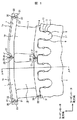
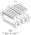
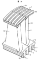
図1および図2は、それぞれ本発明に関わる蒸気タービン動翼を示す図で、図1はタービンロータ軸方向から見た正面図、図2は斜視図である。 FIG. 1 and FIG. 2 are views showing steam turbine rotor blades according to the present invention, respectively, FIG. 1 is a front view seen from the turbine rotor axial direction, and FIG. 2 is a perspective view.
本実施例における蒸気タービン動翼19は、羽根部3と、羽根部の先端に設けられたシュラウド1と、シュラウドの先端のラビリンスシール1aと、タービンロータの外周部に設けられた翼溝6と嵌合するタービンロータの径方向内周側に突出した翼根元部5と、羽根部3と翼根元部5との間に設けられたプラットフォーム部4とを有し、翼溝6に対してタービンロータ軸方向に植え込まれる。
The steam
翼根元部5は翼根元部フック7を有し、また、タービンロータの翼溝6は翼溝フック13を有する。翼根元部5の翼根元部フック7とタービンロータの翼溝6の翼溝フック13との接触部位には、タービンロータ軸方向に向かって挿設される固定ピン9を翼根元部フック7および翼溝フック13に跨って嵌合するための孔部が設けられる。
The
これにより、蒸気タービン動翼19はタービンロータの翼溝6に植え込まれた後、固定ピン9を挿設することによりタービンロータ周方向および半径方向に精度よく固定することができる。
Thus, the steam
本発明のタービン動翼19は、隣接する翼と相対するシュラウド面20,20間に孔21が形成される。この孔内に棒状の部材22を有する。この棒状の部材22と孔21は間隙を有するはめあいとする。この棒状の部材22は、タービンロータが回転することにより蒸気タービン動翼19に発生する遠心力により、孔21の上面に押し付けられる。
In the
これにより、蒸気タービン動翼19は隣り合う翼とシュラウド面の孔21において、棒状の部材22を介して連結されることになる。シュラウド面の孔21における、棒状の部材22を介した連結は、翼の周方向とタービンの軸方向については、孔21と棒状の部材22間にはたらく摩擦力によるものである。
As a result, the steam
このため、蒸気による振動荷重が作用し、タービン動翼19が振動した際に、シュラウド面の孔21と棒状の部材22の接触面においてすべりが発生し、構造減衰を発生し、翼に発生する振動応力を低減する。
For this reason, when a vibration load due to steam is applied and the
この構造減衰を向上させるためには、孔21と棒状の部材22の接触状態が重要である。すなわち、孔21と棒状の部材22の接触面積が大きくなることにより、振動荷重によるタービン動翼19の振動エネルギを散逸させ、振動応力を低減させる効果が高くなると考えられる。
In order to improve this structural damping, the contact state between the
このため、本発明では、蒸気タービン動翼19はタービンロータの翼溝6に植え込まれた後、固定ピン9を挿設することによりタービンロータの周方向および半径方向に精度よく固定することができ、その状態で、隣り合う翼とシュラウド面の孔21において、棒状の部材22を介して連結するため、隣り合う翼の孔21と棒状の部材22の間隙公差を制御することができ、孔21と棒状の部材22の接触面積を大きくすることができる。
For this reason, in the present invention, the steam
これにより、隣り合う翼の孔21と棒状の部材22の構造減衰を向上させ、振動荷重に対する振動応力を低減することができる。
Thereby, the structural attenuation of the
また、シュラウド面20の孔21と棒状の部材22の間隙を、翼根元部及び翼溝と固定ピン9との間隙以上とすることにより、シュラウド面20の孔21と棒状の部材22が、かみ合い、隣り合うシュラウド1が剛な連結となることによる構造減衰の低下や隣り合う翼の変形差を拘束することにより発生するシュラウド1や孔21の高応力を防止することができる。
Further, by making the gap between the
図1,図2では、孔21に設けた棒状の部材22が、孔21から飛び出すことが無いように、シュラウドに設けた孔がロータ軸方向に貫通しないように孔封止23を設けている。孔封止23を、シュラウドの左右で、蒸気の流れ方向に対して、前後相対する位置に設けることにより、蒸気タービン動翼19と棒状の部材22を順次組立ていくことにより、棒状の部材22をシュラウド面20に設けた孔21に封入することができる。
1 and 2, a
ただし、翼リングを形成する最後の翼については、貫通孔とし、穴の封止が必要である。穴の封止は、溶接やねじや、かしめなどでよい。 However, the last wing forming the wing ring is a through hole and needs to be sealed. The hole may be sealed by welding, screws, caulking, or the like.
シュラウド面20の孔21は、貫通孔でもよく、この場合、棒状の部材22の抜け防止は、孔21や部材22のかしめや孔21を溶接やねじなどで封止する。
The
また、構造減衰を高めるために、蒸気タービン動翼19をタービンロータの翼溝6に植え込んだ後、固定ピン9を挿設し、蒸気タービン動翼19をタービンロータの周方向および半径方向に固定した後に、シュラウド面20の孔21の加工を行っても良い。
In order to increase the structural damping, the
これにより、孔21や部材22の接触面積を高め、構造減衰を向上させる接触状態がなされることになる。
Thereby, the contact area which raises the contact area of the
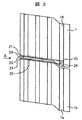
図3は本発明の他の実施例である。隣り合うシュラウド1と周方向にオーバーラップする部位24を設けている。これにより、オーバーラップする部位24を設けることで、棒状の部材22の蒸気下流への抜け防止を行うことができる。
FIG. 3 shows another embodiment of the present invention. A
オーバーラップする部位24に設けた孔25は、円孔とする。
The
これにより、棒状の部材22を隣り合うシュラウド1間に挿入する際に、あらかじめ、棒状の部材22を円孔25に挿入し、保持しておき、そののち隣り合う翼のシュラウド1bを設置することができ、組立性も向上することができる。
Thus, when the rod-
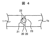
図4は、図3を矢印Aから見たものである。棒状の部材22は、図1,図2の発明と同様に孔封止23により、脱落が防止されるようになっている。
FIG. 4 is a view of FIG. The rod-shaped
図5は本発明の一実施例である。隣り合うシュラウドと周方向にオーバーラップする部位24を設けた上で、孔21を隣接するシュラウド面20に開口する部位を有しない円孔26としている。これにより、棒状の部材22を封入する円孔26を円孔とすることができ、遠心力や棒状の部材22から伝達される力により、シュラウド1の孔回りに発生する応力を低減することができる。
FIG. 5 shows an embodiment of the present invention. A
本発明は、シュラウド1に設けた棒状の部材22と同等の効果を得る目的で、プラットフォーム4の隣り合う面30,30間に孔31を設け、この中に棒状の部材32を封入してもよい。この棒状の部材32は、封止部33により、脱落を防止することも同じ構成である。
In the present invention, for the purpose of obtaining the same effect as the rod-shaped
図1から図5に示した実施例において、孔21,円孔26の内面の硬度を棒状の部材22よりも高めておくことにより以下の効果が得られる。
In the embodiment shown in FIGS. 1 to 5, the following effects can be obtained by increasing the hardness of the inner surfaces of the
即ち、孔21,円孔26の内面が棒状の部材22により磨耗し、棒状の部材22が脱落することを防止することができる。孔21,円孔26の内面の硬度を高める方法としては、硬質Crのめっきなどの処理や窒化,浸炭,高周波焼入れなどの処理が考えられる。
That is, it is possible to prevent the inner surfaces of the
また、棒状の部材22の材質を軽い金属、たとえば、Ti合金やAl合金とすることにより、孔21,円孔26の内面に発生する応力を低減することができる。
Moreover, the stress which generate | occur | produces in the inner surface of the
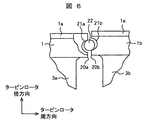
図6および図7は、本発明の他の実施例を示す説明図である。図6は、タービン回転時における、隣接する翼の相対するシュラウド面20a,20bの孔21a,21bと棒状の部材22の位置関係を示した説明図である。
6 and 7 are explanatory views showing another embodiment of the present invention. FIG. 6 is an explanatory diagram showing the positional relationship between the
本実施例では、隣接する翼の相対するシュラウド面20a,20bの孔21a,21bと棒状の部材22の間隙をタービン回転時の隣り合う該シュラウド面20a,20bの孔21a,21bの変位差より小さくしている。これにより、タービン運転時においては、図6に示したように、タービンの回転時は、棒状の部材22はシュラウド面20aの孔21aの上側と接触し、同時に、棒状の部材22はシュラウド面20bの孔21bの下側と接触することになる。この結果、タービン動翼19は、隣り合う翼とシュラウド面の孔21a,21bにおいて、棒状の部材22を介して連結されることになる。シュラウド面の孔21a,21bにおける、棒状の部材22を介した連結は、翼の周方向とタービンの軸方向については、孔21a,21bと棒状の部材22間にはたらく摩擦力によるものである。
In this embodiment, the gap between the
図6においては、シュラウド1の方が、シュラウド1bよりもタービン径方向の変形が小さい。一般的には、翼の背側(吸い込み側)に位置するシュラウドの方が、変形が小さく、翼の腹側(圧力側)に位置するシュラウドの方が変形が大きい。
In FIG. 6, the shroud 1 is less deformed in the turbine radial direction than the
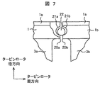
図7は回転停止時や組立時における、隣接する翼の相対するシュラウド面20a,20bの孔21a,21bと棒状の部材22の位置関係を示した説明図である。組立時や回転停止時は、隣り合う翼のシュラウド面の孔21a,21bにおいて、棒状の部材22とシュラウド面の孔21a,21bの間に隙間がある。このため、棒状の部材22は孔21a,21b内を自由に動くことができ、翼を機械的な剛性のある構造物として連結しない。この様な形態であれば、シュラウド面21a,21bに孔21a,21bを設けた後に、棒状の部材22を挿入することが容易である。
FIG. 7 is an explanatory view showing the positional relationship between the
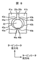
図8にシュラウド面の孔と棒状の部材22の組立時における設定について詳細を示す。はじめに、シュラウド面20aの孔42aの内周における翼の外周に位置する点43aと、棒状の部材22の翼外周に位置し、孔42aの内周の点43aに相対し、運転時に点43aと接触すると考えられる点44aの距離をGaとする。同様に、シュラウド面20bの孔42bの内周における翼の外周に位置する点43bと、棒状の部材22の翼外周に位置し、孔42bの内周の点43bに相対し、運転時に点43bと接触すると考えられる点44bの距離をGbとする。
FIG. 8 shows the details of the setting at the time of assembling the hole on the shroud surface and the rod-shaped
タービン運転時においては、シュラウド41aとシュラウド41bには、遠心力による変形量のちがいや熱変形のちがいにより、タービンロータ径方向の変位に差が生じる。この結果、点43aと点43bにおいてもタービン径方向の変位に差が生じ、この差をU43とする。同様に、シュラウド41aに設けられた孔42aの内周の点45aとシュラウド41bに設けられた孔42bの内周の点45bにおいてもタービン径方向の変位に差が生じ、この差をU45とする。このとき、下式のように、隣り合うシュラウド面20a,20bの孔42a,42bと棒状の部材22の間隙(Ga,Gb)をタービン回転時の隣り合う該シュラウド面の孔の変位差より小さくしている。
During turbine operation, the
|Ga|<|U43|
|Gb|<|U43|
|Ga|<|U45|
|Gb|<|U45|
この結果、タービン運転時において、シュラウド41aよりもシュラウド41bの変位が大きい場合、タービンの回転時は、棒状の部材22はシュラウド41aの孔42aの上側と接触し、同時に、棒状の部材22はシュラウド41bの孔42bの下側と接触することになる。
| Ga | <| U43 |
| Gb | <| U43 |
| Ga | <| U45 |
| Gb | <| U45 |
As a result, during turbine operation, if the displacement of the
産業に用いられるタービンにおいて、遠心力による隣り合うシュラウドの変位差U43やU45は、約数百μmのオーダーであると考えられる。孔42a,42bと棒状の部材22の間隙は、棒状の部材22の断面を円形とした場合は、数μm〜数十μm程度まで小さくすることができる。このため、上記の式のように、シュラウド面に設けた孔42a,42bと棒状の部材22の間隙Ga,Gbを、隣り合うシュラウドの運転時の変位差U43,U45より小さくすることは十分可能である。
In turbines used in industry, the displacement differences U43 and U45 of adjacent shrouds due to centrifugal force are considered to be on the order of about several hundred μm. The gap between the
シュラウドの運転時の変位差U43,U45は、回転数の二乗に比例して大きくなると考えられる。本発明において、孔42a,42bと棒状の部材22は、定格回転数においては接触し、シュラウドが連結することは当然であるが、定格回転数の10〜20%回転数で孔42a,42bと棒状の部材22が接触し、シュラウドが連結するようにGa,Gbを設定することが望ましい。このとき、隣り合うシュラウドの運転時の変位差U43,U45は、有限要素法解析により精度良く求められるので、求められた変位差にいくらかの安全率を見込んだ数値以下に孔42a,42bと棒状の部材22の間隙Ga,Gbを設定すればよい。
It is considered that the displacement differences U43 and U45 during the operation of the shroud increase in proportion to the square of the rotational speed. In the present invention, the
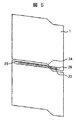
棒状の部材22の孔42a,42b内への封止は、図9に示したように、部材22を挿入した後に、孔の端面をローラやポンチなどによりかしめ、塑性変形部50を形成し、部材22の抜けを防止する。
As shown in FIG. 9, the rod-shaped
図1に示した、プラットフォーム4の隣り合う面30に孔31を設け、この中に棒状の部材32を封入した場合も、シュラウドの孔21と部材22と同様に間隙を設定し、プラットフォーム4を連結させると本発明の効果がさらに向上する。
When holes 31 are provided in
図6〜図9の実施例においては、タービン翼の翼根元部と翼溝との間にピンを設けたものについて記載したが、翼溝部にピンを有しない、クリスマスツリー型のダブテールを有するタービン翼に本実施例を適用しても良い。 In the embodiments of FIGS. 6 to 9, the turbine blades having the pins provided between the blade roots and the blade grooves are described. However, the turbine having a Christmas tree type dovetail having no pins in the blade grooves. This embodiment may be applied to the wing.
また、本発明は、蒸気タービン,ガスタービン,圧縮機,送付機に用いるタービン翼に適用することができる。 The present invention can also be applied to turbine blades used in steam turbines, gas turbines, compressors, and delivery machines.
1,1b シュラウド
3 羽根部
4 プラットフォーム部
5 翼根元部
6 翼溝
8 タービンロータ
9 固定ピン
19 蒸気タービン動翼
21,21a,21b,31,42a,42b 孔
22,32 棒状の部材
1,
Claims (11)
タービンロータの外周部に設けられた翼溝と嵌合するタービンロータの径方向内周側に突出した翼根元部と、
前記羽根部と前記翼根元部との間に設けられたプラットフォーム部と、
前記翼根元部と前記翼溝との間に設けられたピンと、
隣り合う翼の相対する前記シュラウドの面間に形成される孔と、
前記孔の内に、前記孔との間に間隙を有して設けられた棒状の部材とを有し、
前記孔と前記棒状の部材の組立時における間隙を、タービン回転時の隣り合う前記シュラウド面の孔の変位差より小さくした蒸気タービン動翼組立体。 A blade portion, and a shroud provided at the tip of the blade portion;
A blade root portion protruding to the radially inner peripheral side of the turbine rotor to be fitted with a blade groove provided on the outer peripheral portion of the turbine rotor;
A platform portion provided between the blade portion and the blade root portion;
A pin provided between the blade root and the blade groove;
A hole formed between the opposing surfaces of the shroud of adjacent wings;
Within the holes, have a bar-shaped member provided with a gap between the hole,
A steam turbine rotor blade assembly in which a gap during assembly of the hole and the rod-shaped member is made smaller than a displacement difference between adjacent holes in the shroud surface during turbine rotation .
タービンロータの外周部に設けられた翼溝と嵌合するタービンロータの径方向内周側に突出した翼根元部と、
前記羽根部と前記翼根元部との間に設けられたプラットフォーム部と、
隣り合う翼の相対する前記シュラウドの面間に形成される孔と、
前記孔の内に、前記孔との間に間隙を有して設けられた棒状の部材とを有し、
前記孔と前記棒状の部材の組立時における間隙を、タービン回転時の隣り合う前記シュラウド面の孔の変位差より小さくした蒸気タービン動翼組立体。 A blade portion, and a shroud provided at the tip of the blade portion;
A blade root portion protruding to the radially inner peripheral side of the turbine rotor to be fitted with a blade groove provided on the outer peripheral portion of the turbine rotor;
A platform portion provided between the blade portion and the blade root portion;
A hole formed between the opposing surfaces of the shroud of adjacent wings;
Within the hole, a rod-shaped member provided with a gap between the hole ,
A steam turbine rotor blade assembly in which a gap during assembly of the hole and the rod-shaped member is made smaller than a displacement difference between adjacent holes in the shroud surface during turbine rotation.
Priority Applications (1)
| Application Number | Priority Date | Filing Date | Title |
|---|---|---|---|
| JP2008231617A JP4991663B2 (en) | 2007-09-11 | 2008-09-10 | Steam turbine blade assembly |
Applications Claiming Priority (3)
| Application Number | Priority Date | Filing Date | Title |
|---|---|---|---|
| JP2007234858 | 2007-09-11 | ||
| JP2007234858 | 2007-09-11 | ||
| JP2008231617A JP4991663B2 (en) | 2007-09-11 | 2008-09-10 | Steam turbine blade assembly |
Related Child Applications (1)
| Application Number | Title | Priority Date | Filing Date |
|---|---|---|---|
| JP2012102003A Division JP5272094B2 (en) | 2007-09-11 | 2012-04-27 | Turbine blade assembly |
Publications (2)
| Publication Number | Publication Date |
|---|---|
| JP2009085214A JP2009085214A (en) | 2009-04-23 |
| JP4991663B2 true JP4991663B2 (en) | 2012-08-01 |
Family
ID=40534394
Family Applications (2)
| Application Number | Title | Priority Date | Filing Date |
|---|---|---|---|
| JP2008231617A Expired - Fee Related JP4991663B2 (en) | 2007-09-11 | 2008-09-10 | Steam turbine blade assembly |
| JP2012102003A Expired - Fee Related JP5272094B2 (en) | 2007-09-11 | 2012-04-27 | Turbine blade assembly |
Family Applications After (1)
| Application Number | Title | Priority Date | Filing Date |
|---|---|---|---|
| JP2012102003A Expired - Fee Related JP5272094B2 (en) | 2007-09-11 | 2012-04-27 | Turbine blade assembly |
Country Status (3)
| Country | Link |
|---|---|
| US (2) | US8257044B2 (en) |
| JP (2) | JP4991663B2 (en) |
| KR (2) | KR101120578B1 (en) |
Families Citing this family (32)
| Publication number | Priority date | Publication date | Assignee | Title |
|---|---|---|---|---|
| JP5090287B2 (en) * | 2008-08-07 | 2012-12-05 | 株式会社日立製作所 | Turbine blade and its fixed structure |
| US8277189B2 (en) * | 2009-11-12 | 2012-10-02 | General Electric Company | Turbine blade and rotor |
| US20110158814A1 (en) * | 2009-12-31 | 2011-06-30 | General Electric Company | Turbine engine rotor blades and rotor wheels |
| JP5380371B2 (en) * | 2010-06-04 | 2014-01-08 | 株式会社日立製作所 | Turbine blade |
| FR2963381B1 (en) * | 2010-07-27 | 2015-04-10 | Snecma | INTER-AUB SEALING FOR A TURBINE OR TURBOMACHINE COMPRESSOR WHEEL |
| JP5591152B2 (en) * | 2011-02-28 | 2014-09-17 | 三菱重工業株式会社 | Turbine blade |
| US8821125B2 (en) * | 2012-02-06 | 2014-09-02 | Alstom Technology Ltd. | Turbine blade having improved flutter capability and increased turbine stage output |
| US10309235B2 (en) | 2012-08-27 | 2019-06-04 | United Technologies Corporation | Shiplap cantilevered stator |
| JP6134878B2 (en) * | 2012-09-27 | 2017-05-31 | 三菱日立パワーシステムズ株式会社 | Turbine vane damping structure |
| US9194238B2 (en) * | 2012-11-28 | 2015-11-24 | General Electric Company | System for damping vibrations in a turbine |
| EP2803821A1 (en) * | 2013-05-13 | 2014-11-19 | Siemens Aktiengesellschaft | Blade device, blade system, and corresponding method of manufacturing a blade system |
| KR101513062B1 (en) * | 2013-10-16 | 2015-04-17 | 두산중공업 주식회사 | Steam turbine |
| DE102013224199A1 (en) * | 2013-11-27 | 2015-05-28 | MTU Aero Engines AG | Gas turbine blade |
| FR3014942B1 (en) * | 2013-12-18 | 2016-01-08 | Snecma | DAWN, WHEEL IN AUBES AND TURBOMACHINE; PROCESS FOR MANUFACTURING DAWN |
| JP6270531B2 (en) * | 2014-02-21 | 2018-01-31 | 三菱日立パワーシステムズ株式会社 | Rotor body and rotating machine |
| US10375901B2 (en) | 2014-12-09 | 2019-08-13 | Mtd Products Inc | Blower/vacuum |
| US10281045B2 (en) | 2015-02-20 | 2019-05-07 | Rolls-Royce North American Technologies Inc. | Apparatus and methods for sealing components in gas turbine engines |
| US9759079B2 (en) * | 2015-05-28 | 2017-09-12 | Rolls-Royce Corporation | Split line flow path seals |
| US10458263B2 (en) | 2015-10-12 | 2019-10-29 | Rolls-Royce North American Technologies Inc. | Turbine shroud with sealing features |
| EP3269933A1 (en) * | 2016-07-14 | 2018-01-17 | Siemens Aktiengesellschaft | Blade formation for a flow machine |
| KR101864486B1 (en) * | 2016-07-22 | 2018-06-04 | 두산중공업 주식회사 | Turbine with a cooling passage |
| US10301955B2 (en) | 2016-11-29 | 2019-05-28 | Rolls-Royce North American Technologies Inc. | Seal assembly for gas turbine engine components |
| US10443420B2 (en) | 2017-01-11 | 2019-10-15 | Rolls-Royce North American Technologies Inc. | Seal assembly for gas turbine engine components |
| US10577977B2 (en) | 2017-02-22 | 2020-03-03 | Rolls-Royce Corporation | Turbine shroud with biased retaining ring |
| EP3438410B1 (en) | 2017-08-01 | 2021-09-29 | General Electric Company | Sealing system for a rotary machine |
| US10443389B2 (en) | 2017-11-09 | 2019-10-15 | Douglas James Dietrich | Turbine blade having improved flutter capability and increased turbine stage output |
| US10724535B2 (en) * | 2017-11-14 | 2020-07-28 | Raytheon Technologies Corporation | Fan assembly of a gas turbine engine with a tip shroud |
| US10718226B2 (en) | 2017-11-21 | 2020-07-21 | Rolls-Royce Corporation | Ceramic matrix composite component assembly and seal |
| US10927692B2 (en) * | 2018-08-06 | 2021-02-23 | General Electric Company | Turbomachinery sealing apparatus and method |
| KR102111662B1 (en) * | 2018-09-21 | 2020-05-15 | 두산중공업 주식회사 | Turbine blade having damping device |
| IT201900013854A1 (en) | 2019-08-02 | 2021-02-02 | Ge Avio Srl | TURBINE MOTOR WITH SNAP-IN GASKETS. |
| US11781440B2 (en) * | 2021-03-09 | 2023-10-10 | Rtx Corporation | Scalloped mateface seal arrangement for CMC platforms |
Family Cites Families (22)
| Publication number | Priority date | Publication date | Assignee | Title |
|---|---|---|---|---|
| JPS5776208A (en) | 1980-10-30 | 1982-05-13 | Toshiba Corp | Turbine vane |
| FR2501336B1 (en) | 1981-03-09 | 1986-02-28 | Cibie Projecteurs | LIGHT EMITTING ASSEMBLY FOR MOTOR VEHICLES |
| JPS57158901U (en) * | 1981-03-31 | 1982-10-06 | ||
| JPS57210104A (en) * | 1981-06-17 | 1982-12-23 | Hitachi Ltd | Device for securing moving vane of turbine |
| JPS58176402A (en) | 1982-04-10 | 1983-10-15 | Toshiba Corp | Vibration damping device for turbine moving blade |
| JPS63150002A (en) | 1986-12-13 | 1988-06-22 | ダイワ精工株式会社 | Ski boots |
| GB8705216D0 (en) * | 1987-03-06 | 1987-04-08 | Rolls Royce Plc | Rotor assembly |
| JPS63150002U (en) * | 1987-03-25 | 1988-10-03 | ||
| JPH0586803A (en) * | 1991-09-25 | 1993-04-06 | Mitsubishi Heavy Ind Ltd | Triple pin bucket |
| JPH08303205A (en) * | 1995-05-11 | 1996-11-19 | Hitachi Ltd | Turbine blades |
| JPH11148305A (en) * | 1997-11-17 | 1999-06-02 | Hitachi Ltd | Turbine blade |
| JP2000204901A (en) * | 1999-01-08 | 2000-07-25 | Mitsubishi Heavy Ind Ltd | Damping structure of rotor blade in axial flow rotating machine |
| JP3933130B2 (en) * | 2001-08-03 | 2007-06-20 | 株式会社日立製作所 | Turbine blade |
| US7080971B2 (en) * | 2003-03-12 | 2006-07-25 | Florida Turbine Technologies, Inc. | Cooled turbine spar shell blade construction |
| DE10340773A1 (en) * | 2003-09-02 | 2005-03-24 | Man Turbomaschinen Ag | Rotor of a steam or gas turbine |
| JP2006076638A (en) * | 2004-09-10 | 2006-03-23 | Yasutaka Matsuo | Rice ball packaging sheet |
| JP2007231868A (en) * | 2006-03-02 | 2007-09-13 | Hitachi Ltd | Steam turbine blade, steam turbine using the same, and steam turbine power plant |
| US8579590B2 (en) * | 2006-05-18 | 2013-11-12 | Wood Group Heavy Industrial Turbines Ag | Turbomachinery blade having a platform relief hole, platform cooling holes, and trailing edge cutback |
| US7534090B2 (en) * | 2006-06-13 | 2009-05-19 | General Electric Company | Enhanced bucket vibration system |
| JP2007332893A (en) * | 2006-06-16 | 2007-12-27 | Mitsubishi Heavy Ind Ltd | Vibration damping and fretting preventive structure of axial flow turbine blade |
| EP1941967A1 (en) * | 2007-01-08 | 2008-07-09 | ALSTOM Technology Ltd | Method and device for pin removal in a confined space |
| US7976281B2 (en) * | 2007-05-15 | 2011-07-12 | General Electric Company | Turbine rotor blade and method of assembling the same |
-
2008
- 2008-09-10 JP JP2008231617A patent/JP4991663B2/en not_active Expired - Fee Related
- 2008-09-10 US US12/207,901 patent/US8257044B2/en not_active Expired - Fee Related
- 2008-09-10 KR KR1020080089269A patent/KR101120578B1/en not_active Expired - Fee Related
-
2011
- 2011-12-08 KR KR1020110131318A patent/KR101199553B1/en not_active Expired - Fee Related
-
2012
- 2012-04-27 JP JP2012102003A patent/JP5272094B2/en not_active Expired - Fee Related
- 2012-08-03 US US13/566,382 patent/US8591194B2/en active Active
Also Published As
| Publication number | Publication date |
|---|---|
| KR20120005420A (en) | 2012-01-16 |
| US20120301311A1 (en) | 2012-11-29 |
| KR101199553B1 (en) | 2012-11-12 |
| KR101120578B1 (en) | 2012-03-09 |
| US8591194B2 (en) | 2013-11-26 |
| KR20090027165A (en) | 2009-03-16 |
| JP2012140971A (en) | 2012-07-26 |
| US8257044B2 (en) | 2012-09-04 |
| US20090097980A1 (en) | 2009-04-16 |
| JP2009085214A (en) | 2009-04-23 |
| JP5272094B2 (en) | 2013-08-28 |
Similar Documents
| Publication | Publication Date | Title |
|---|---|---|
| JP4991663B2 (en) | Steam turbine blade assembly | |
| JP4886735B2 (en) | Turbine blade assembly and steam turbine | |
| JP5852249B2 (en) | gas turbine | |
| US8231352B2 (en) | Vibration damper assembly | |
| JP2005113916A (en) | Blade damper for turbo machine and its assembling method | |
| CA2735493C (en) | Turbine blade retention device | |
| EP2758634A1 (en) | Impingement cooling of turbine blades or vanes | |
| US20160108737A1 (en) | Blade system, and corresponding method of manufacturing a blade system | |
| JP2012052523A (en) | Turbine blade assembly | |
| US10072508B2 (en) | Turbomachine rotor with optimised bearing surfaces | |
| JP2010230007A (en) | Rotor assembly of turbomachine and its assembly method | |
| EP2601385B1 (en) | Turbomachine rotor with blade roots with adjusting protrusions | |
| EP2151545B1 (en) | Turbine blade and fixation structure thereof | |
| US10830253B2 (en) | Rotor, axial compressor, installation method | |
| US7503751B2 (en) | Apparatus and method for attaching a rotor blade to a rotor | |
| US10006296B2 (en) | Shroud for pre-twisted airfoils | |
| JP6785555B2 (en) | How to assemble the rotor blade to the turbine rotor | |
| CN110603372A (en) | Pin for reducing relative rotational movement of a disk and a spacer of a turbine engine | |
| JP2021124105A (en) | Turbine wheel and fixing method of wire holding pin of turbine wheel | |
| CN105723053A (en) | Bucket locking assembly of a turbomachine and securing method | |
| JP4871919B2 (en) | Turbine blade fixed structure | |
| JP5881430B2 (en) | Blade root spring, turbine rotor including the same, and gas turbine | |
| JP5703923B2 (en) | Scroll housing positioning structure and supercharger | |
| JP2023074610A (en) | Turbine rotor and manufacturing method of the same |
Legal Events
| Date | Code | Title | Description |
|---|---|---|---|
| A621 | Written request for application examination |
Free format text: JAPANESE INTERMEDIATE CODE: A621 Effective date: 20100326 |
|
| A977 | Report on retrieval |
Free format text: JAPANESE INTERMEDIATE CODE: A971007 Effective date: 20110922 |
|
| A131 | Notification of reasons for refusal |
Free format text: JAPANESE INTERMEDIATE CODE: A131 Effective date: 20111004 |
|
| A521 | Written amendment |
Free format text: JAPANESE INTERMEDIATE CODE: A523 Effective date: 20111205 |
|
| TRDD | Decision of grant or rejection written | ||
| A01 | Written decision to grant a patent or to grant a registration (utility model) |
Free format text: JAPANESE INTERMEDIATE CODE: A01 Effective date: 20120410 |
|
| A01 | Written decision to grant a patent or to grant a registration (utility model) |
Free format text: JAPANESE INTERMEDIATE CODE: A01 |
|
| A61 | First payment of annual fees (during grant procedure) |
Free format text: JAPANESE INTERMEDIATE CODE: A61 Effective date: 20120507 |
|
| FPAY | Renewal fee payment (event date is renewal date of database) |
Free format text: PAYMENT UNTIL: 20150511 Year of fee payment: 3 |
|
| S111 | Request for change of ownership or part of ownership |
Free format text: JAPANESE INTERMEDIATE CODE: R313111 |
|
| R350 | Written notification of registration of transfer |
Free format text: JAPANESE INTERMEDIATE CODE: R350 |
|
| R250 | Receipt of annual fees |
Free format text: JAPANESE INTERMEDIATE CODE: R250 |
|
| R250 | Receipt of annual fees |
Free format text: JAPANESE INTERMEDIATE CODE: R250 |
|
| R250 | Receipt of annual fees |
Free format text: JAPANESE INTERMEDIATE CODE: R250 |
|
| LAPS | Cancellation because of no payment of annual fees |