JP4987481B2 - Determining location information - Google Patents
Determining location information Download PDFInfo
- Publication number
- JP4987481B2 JP4987481B2 JP2006538922A JP2006538922A JP4987481B2 JP 4987481 B2 JP4987481 B2 JP 4987481B2 JP 2006538922 A JP2006538922 A JP 2006538922A JP 2006538922 A JP2006538922 A JP 2006538922A JP 4987481 B2 JP4987481 B2 JP 4987481B2
- Authority
- JP
- Japan
- Prior art keywords
- signal
- receiving
- transmitter
- frequency
- pulse
- Prior art date
- Legal status (The legal status is an assumption and is not a legal conclusion. Google has not performed a legal analysis and makes no representation as to the accuracy of the status listed.)
- Active
Links
- 238000000034 method Methods 0.000 claims description 146
- 238000001514 detection method Methods 0.000 claims description 130
- 238000012545 processing Methods 0.000 claims description 81
- 238000004891 communication Methods 0.000 claims description 55
- 230000004044 response Effects 0.000 claims description 49
- 239000000523 sample Substances 0.000 claims description 49
- 230000008569 process Effects 0.000 claims description 44
- 238000006073 displacement reaction Methods 0.000 claims description 22
- 239000000758 substrate Substances 0.000 claims description 15
- 238000000926 separation method Methods 0.000 claims description 7
- 230000001419 dependent effect Effects 0.000 claims 1
- 230000006870 function Effects 0.000 description 58
- 230000005540 biological transmission Effects 0.000 description 48
- 238000005070 sampling Methods 0.000 description 48
- 238000010586 diagram Methods 0.000 description 39
- 238000005259 measurement Methods 0.000 description 30
- 238000001208 nuclear magnetic resonance pulse sequence Methods 0.000 description 23
- 101001093748 Homo sapiens Phosphatidylinositol N-acetylglucosaminyltransferase subunit P Proteins 0.000 description 21
- 238000004422 calculation algorithm Methods 0.000 description 18
- 230000008859 change Effects 0.000 description 15
- 230000005855 radiation Effects 0.000 description 11
- 230000001360 synchronised effect Effects 0.000 description 11
- 238000001914 filtration Methods 0.000 description 10
- 230000000694 effects Effects 0.000 description 8
- 238000004364 calculation method Methods 0.000 description 7
- 238000004590 computer program Methods 0.000 description 7
- 230000033001 locomotion Effects 0.000 description 6
- 238000007726 management method Methods 0.000 description 6
- 230000007423 decrease Effects 0.000 description 5
- 230000001976 improved effect Effects 0.000 description 5
- 238000007781 pre-processing Methods 0.000 description 5
- 230000001960 triggered effect Effects 0.000 description 5
- 230000006399 behavior Effects 0.000 description 4
- 230000008901 benefit Effects 0.000 description 4
- 238000013461 design Methods 0.000 description 4
- 235000013305 food Nutrition 0.000 description 4
- 230000007274 generation of a signal involved in cell-cell signaling Effects 0.000 description 4
- 230000004807 localization Effects 0.000 description 4
- 101000987581 Homo sapiens Perforin-1 Proteins 0.000 description 3
- 102100028467 Perforin-1 Human genes 0.000 description 3
- 230000002159 abnormal effect Effects 0.000 description 3
- 230000002547 anomalous effect Effects 0.000 description 3
- 239000003795 chemical substances by application Substances 0.000 description 3
- 239000013078 crystal Substances 0.000 description 3
- 238000013480 data collection Methods 0.000 description 3
- 230000001934 delay Effects 0.000 description 3
- 230000003111 delayed effect Effects 0.000 description 3
- 238000005516 engineering process Methods 0.000 description 3
- 238000001228 spectrum Methods 0.000 description 3
- 101100137546 Arabidopsis thaliana PRF2 gene Proteins 0.000 description 2
- 238000012935 Averaging Methods 0.000 description 2
- 101100191501 Zea mays PRO2 gene Proteins 0.000 description 2
- 238000013459 approach Methods 0.000 description 2
- 238000010276 construction Methods 0.000 description 2
- 230000003993 interaction Effects 0.000 description 2
- 238000011835 investigation Methods 0.000 description 2
- 230000007246 mechanism Effects 0.000 description 2
- 238000010606 normalization Methods 0.000 description 2
- 230000035515 penetration Effects 0.000 description 2
- 230000010363 phase shift Effects 0.000 description 2
- 230000001902 propagating effect Effects 0.000 description 2
- 230000035945 sensitivity Effects 0.000 description 2
- 238000007493 shaping process Methods 0.000 description 2
- 230000003595 spectral effect Effects 0.000 description 2
- 239000000654 additive Substances 0.000 description 1
- 230000000996 additive effect Effects 0.000 description 1
- 239000000853 adhesive Substances 0.000 description 1
- 230000001070 adhesive effect Effects 0.000 description 1
- 238000004458 analytical method Methods 0.000 description 1
- 230000033228 biological regulation Effects 0.000 description 1
- 230000036772 blood pressure Effects 0.000 description 1
- 238000006243 chemical reaction Methods 0.000 description 1
- 230000000295 complement effect Effects 0.000 description 1
- 239000002131 composite material Substances 0.000 description 1
- 230000000593 degrading effect Effects 0.000 description 1
- 230000002349 favourable effect Effects 0.000 description 1
- 230000000977 initiatory effect Effects 0.000 description 1
- 238000009434 installation Methods 0.000 description 1
- 230000010354 integration Effects 0.000 description 1
- 230000001788 irregular Effects 0.000 description 1
- 239000011159 matrix material Substances 0.000 description 1
- 238000012986 modification Methods 0.000 description 1
- 230000004048 modification Effects 0.000 description 1
- 238000012544 monitoring process Methods 0.000 description 1
- 238000012805 post-processing Methods 0.000 description 1
- 230000000750 progressive effect Effects 0.000 description 1
- 238000012887 quadratic function Methods 0.000 description 1
- 238000011084 recovery Methods 0.000 description 1
- 230000010076 replication Effects 0.000 description 1
- 230000000630 rising effect Effects 0.000 description 1
- 238000011895 specific detection Methods 0.000 description 1
- 238000010408 sweeping Methods 0.000 description 1
- 230000007474 system interaction Effects 0.000 description 1
- 238000012546 transfer Methods 0.000 description 1
Images


Classifications
-
- G—PHYSICS
- G01—MEASURING; TESTING
- G01S—RADIO DIRECTION-FINDING; RADIO NAVIGATION; DETERMINING DISTANCE OR VELOCITY BY USE OF RADIO WAVES; LOCATING OR PRESENCE-DETECTING BY USE OF THE REFLECTION OR RERADIATION OF RADIO WAVES; ANALOGOUS ARRANGEMENTS USING OTHER WAVES
- G01S5/00—Position-fixing by co-ordinating two or more direction or position line determinations; Position-fixing by co-ordinating two or more distance determinations
- G01S5/02—Position-fixing by co-ordinating two or more direction or position line determinations; Position-fixing by co-ordinating two or more distance determinations using radio waves
- G01S5/04—Position of source determined by a plurality of spaced direction-finders
-
- G—PHYSICS
- G01—MEASURING; TESTING
- G01S—RADIO DIRECTION-FINDING; RADIO NAVIGATION; DETERMINING DISTANCE OR VELOCITY BY USE OF RADIO WAVES; LOCATING OR PRESENCE-DETECTING BY USE OF THE REFLECTION OR RERADIATION OF RADIO WAVES; ANALOGOUS ARRANGEMENTS USING OTHER WAVES
- G01S13/00—Systems using the reflection or reradiation of radio waves, e.g. radar systems; Analogous systems using reflection or reradiation of waves whose nature or wavelength is irrelevant or unspecified
- G01S13/02—Systems using reflection of radio waves, e.g. primary radar systems; Analogous systems
- G01S13/0209—Systems with very large relative bandwidth, i.e. larger than 10 %, e.g. baseband, pulse, carrier-free, ultrawideband
-
- G—PHYSICS
- G01—MEASURING; TESTING
- G01S—RADIO DIRECTION-FINDING; RADIO NAVIGATION; DETERMINING DISTANCE OR VELOCITY BY USE OF RADIO WAVES; LOCATING OR PRESENCE-DETECTING BY USE OF THE REFLECTION OR RERADIATION OF RADIO WAVES; ANALOGOUS ARRANGEMENTS USING OTHER WAVES
- G01S13/00—Systems using the reflection or reradiation of radio waves, e.g. radar systems; Analogous systems using reflection or reradiation of waves whose nature or wavelength is irrelevant or unspecified
- G01S13/87—Combinations of radar systems, e.g. primary radar and secondary radar
- G01S13/878—Combination of several spaced transmitters or receivers of known location for determining the position of a transponder or a reflector
-
- G—PHYSICS
- G01—MEASURING; TESTING
- G01S—RADIO DIRECTION-FINDING; RADIO NAVIGATION; DETERMINING DISTANCE OR VELOCITY BY USE OF RADIO WAVES; LOCATING OR PRESENCE-DETECTING BY USE OF THE REFLECTION OR RERADIATION OF RADIO WAVES; ANALOGOUS ARRANGEMENTS USING OTHER WAVES
- G01S13/00—Systems using the reflection or reradiation of radio waves, e.g. radar systems; Analogous systems using reflection or reradiation of waves whose nature or wavelength is irrelevant or unspecified
- G01S13/74—Systems using reradiation of radio waves, e.g. secondary radar systems; Analogous systems
- G01S13/76—Systems using reradiation of radio waves, e.g. secondary radar systems; Analogous systems wherein pulse-type signals are transmitted
- G01S13/765—Systems using reradiation of radio waves, e.g. secondary radar systems; Analogous systems wherein pulse-type signals are transmitted with exchange of information between interrogator and responder
-
- G—PHYSICS
- G01—MEASURING; TESTING
- G01S—RADIO DIRECTION-FINDING; RADIO NAVIGATION; DETERMINING DISTANCE OR VELOCITY BY USE OF RADIO WAVES; LOCATING OR PRESENCE-DETECTING BY USE OF THE REFLECTION OR RERADIATION OF RADIO WAVES; ANALOGOUS ARRANGEMENTS USING OTHER WAVES
- G01S13/00—Systems using the reflection or reradiation of radio waves, e.g. radar systems; Analogous systems using reflection or reradiation of waves whose nature or wavelength is irrelevant or unspecified
- G01S13/88—Radar or analogous systems specially adapted for specific applications
- G01S13/887—Radar or analogous systems specially adapted for specific applications for detection of concealed objects, e.g. contraband or weapons
- G01S13/888—Radar or analogous systems specially adapted for specific applications for detection of concealed objects, e.g. contraband or weapons through wall detection
-
- G—PHYSICS
- G01—MEASURING; TESTING
- G01S—RADIO DIRECTION-FINDING; RADIO NAVIGATION; DETERMINING DISTANCE OR VELOCITY BY USE OF RADIO WAVES; LOCATING OR PRESENCE-DETECTING BY USE OF THE REFLECTION OR RERADIATION OF RADIO WAVES; ANALOGOUS ARRANGEMENTS USING OTHER WAVES
- G01S13/00—Systems using the reflection or reradiation of radio waves, e.g. radar systems; Analogous systems using reflection or reradiation of waves whose nature or wavelength is irrelevant or unspecified
- G01S13/88—Radar or analogous systems specially adapted for specific applications
- G01S13/93—Radar or analogous systems specially adapted for specific applications for anti-collision purposes
- G01S13/931—Radar or analogous systems specially adapted for specific applications for anti-collision purposes of land vehicles
- G01S2013/9329—Radar or analogous systems specially adapted for specific applications for anti-collision purposes of land vehicles cooperating with reflectors or transponders
Description
本発明は、送信機を組み込んだ物体に関する位置情報を決定するための機器、放射物体を求めて検出体積内を検索するための機器、物体を位置決定するためのシステムに関し、詳細には、物体位置決めシステムにおいて物体で使用するための送信機を組み込んだ物体、位置情報を決定する方法、コンピュータ可読媒体、コンピュータプログラム製品、および信号に関する。 The present invention relates to a device for determining position information relating to an object incorporating a transmitter, a device for searching a detection volume for a radiating object, a system for locating an object, and more particularly to an object The present invention relates to an object incorporating a transmitter for use with the object in a positioning system, a method for determining position information, a computer readable medium, a computer program product, and a signal.
本発明は、物体追跡システム、侵入検出器システム、在庫管理、車両衝突検出、ならびにセキュリティおよび作業員追跡システムの分野で具体的な用途が見出せる。
「能動」送信機タグを追跡するための、知られている従来技術のシステムが、「Ultra−wideband precision asset location system」(IEEE Conference on Ultra Wideband Systems and Technologies、2002年5月)と題する論文で公開されている。このシステムでは、船内の貨物室の広く間隔の空いた隅部の場所に配置された複数の受信アンテナを使用して、貨物室内の貨物に取り付けられた送信機タグから放射される超広帯域信号を検出する。円弧近似技法では、受信アンテナの中央コンピュータとの同期を利用し、各アンテナにおける識別パルスの到着時間の知識を使用し、3次元での物体の位置を確定する。
The present invention finds particular application in the fields of object tracking systems, intrusion detector systems, inventory management, vehicle collision detection, and security and worker tracking systems.
A known prior art system for tracking "active" transmitter tags is "Ultra-wideband asset asset location system" (IEEE Conferencing on Ultra Wideband Systems and Technologies 5th Year, 200th Year). It has been published. This system uses multiple receiving antennas located at widely spaced corners of the cargo compartment on board the ship to transmit ultra-wideband signals radiated from transmitter tags attached to cargo in the cargo compartment. To detect. The arc approximation technique uses the synchronization of the receiving antenna with the central computer and uses knowledge of the arrival time of the identification pulse at each antenna to determine the position of the object in three dimensions.
従来技術のシステムでは、物体から受信機の1つへの直接信号が、遅延した反射信号と比べて弱い場合、例えば、物体と受信機の間に障害物がある場合、問題が生じる。この場合、遅延信号反射がパルス到着時間として誤って識別されることがあり、その結果、位置推定手順で劇的に大きなエラーが生じる可能性がある。また、各従来技術の受信機ユニットは比較的単純であるが、各受信機とコンピュータとを正確に同期させる必要があるので、正確で高価なタイミング回路が必要となることがある。さらに、円弧近似技法を利用すると、システムの精度が制限されることがあり、あいまいさも生じる可能性がある。 In prior art systems, problems arise when the direct signal from the object to one of the receivers is weak compared to the delayed reflected signal, for example when there is an obstacle between the object and the receiver. In this case, delayed signal reflections may be mistakenly identified as pulse arrival times, which can result in dramatically large errors in the position estimation procedure. Also, although each prior art receiver unit is relatively simple, accurate and expensive timing circuitry may be required because each receiver and computer must be accurately synchronized. In addition, the use of arc approximation techniques can limit the accuracy of the system and can cause ambiguity.
従来技術で明らかになった問題を克服するために、送信機を組み込んだ物体に関する位置情報を決定するための機器が提供される。この機器は、物体における送信機から送信された信号を受信するための手段と、受信手段に結合され、物体の角位置を決定することのできる出力を生成するための検出手段とを含む。 In order to overcome the problems identified in the prior art, an apparatus is provided for determining position information about an object incorporating a transmitter. The apparatus includes means for receiving a signal transmitted from a transmitter at the object, and detection means coupled to the receiving means for generating an output capable of determining the angular position of the object.
密接に関係する一態様においては、送信機を組み込んだ物体に関する位置情報を決定するための機器であって、
組み込まれた送信機によって送信される信号パルスを受信するための手段であって、受信するための前記手段が、単一のハウジング内に、または共通の基板上に配置され、前記信号パルスが好ましくは超広帯域信号パルスである手段と、
受信手段に結合され、物体の角位置をそこから決定することができる出力を生成するための検出手段とを含み、
受信するための手段が複数の受信エレメントを含み、検出手段が、複数の受信エレメントで受信された信号パルスの相対タイミングを検出し、それによって角位置を決定することができるように適合される機器が提供される。
In one closely related aspect, an apparatus for determining location information about an object incorporating a transmitter comprising:
Means for receiving a signal pulse transmitted by an integrated transmitter, wherein said means for receiving is arranged in a single housing or on a common substrate, preferably said signal pulse Means that is an ultra-wideband signal pulse;
Detecting means coupled to the receiving means for generating an output from which the angular position of the object can be determined;
An apparatus adapted for the means for receiving to include a plurality of receiving elements and for the detecting means to detect the relative timing of the signal pulses received at the plurality of receiving elements and thereby determine the angular position Is provided.
いずれの事象においても、好ましくは、受信手段が、特性パルス周波数を有するパルス列を受信するように適合され、検出手段が、受信パルス列を表す信号を出力するように適合される。 In any event, preferably the receiving means is adapted to receive a pulse train having a characteristic pulse frequency and the detecting means is adapted to output a signal representative of the received pulse train.
物体の到達距離ではなく角位置が得られる出力を生成することによって、物体の位置をより高い精度で決定することができる。
この機器は、UWBパルスを非同期的に(すなわち、同時送受信制御の下ではなく)送信することができる。到達距離は短いことがあり、一般に50メートル未満、通常、10メートル未満である。精度は、15cm未満とすることができる。好ましくは、複数のタグを同時に扱うことができる。別々の基地局を使用して、正確な位置を決定することができる。
By generating an output that obtains the angular position rather than the object reachable distance, the position of the object can be determined with higher accuracy.
This device can transmit UWB pulses asynchronously (ie, not under simultaneous transmit / receive control). The reach may be short, generally less than 50 meters, usually less than 10 meters. The accuracy can be less than 15 cm. Preferably, a plurality of tags can be handled simultaneously. Different base stations can be used to determine the exact location.
当機器は、広範な適用範囲を有することができ、アレイデータ処理またはビーム形成を使用せずに、時間領域プロセスにおいて、遅延を決定して、2次元ではなく3次元での角位置(または到来角)を見つけることができる。各受信機は、角位置を個別に決定することができる。マルチパスを活用して、性能を高める必要はない。この機器は、恒久的または半恒久的に固定することができる。この機器は、2つのアンテナ(必ずしも半波長の間隔を空ける必要はない)および複数の基地局を使用して、位置を決定することができる。 The instrument can have a wide range of applications, determine the delay in a time domain process, without using array data processing or beamforming, and angular position (or arrival in 3D instead of 2D) Corner). Each receiver can determine the angular position individually. There is no need to use multipath to increase performance. This device can be permanently or semi-permanently fixed. The device can determine location using two antennas (not necessarily spaced half-wave apart) and multiple base stations.
この機器は、好ましくは、在庫品目に取り付けられた能動送信機タグを追跡する在庫管理システムなどの位置決めシステム内に設けられる、受信ユニット、またはセンサである。 This equipment is preferably a receiving unit or sensor provided in a positioning system, such as an inventory management system that tracks active transmitter tags attached to inventory items.
好ましくは、信号を受信する手段が、受動システムで受信される信号とは一般に異なるダイナミックレンジを有する信号を受信するように適合される。能動システムでは、信号強度は、受動システムでの1/D4に対して、1/D2(ここで、Dは追跡される物体までの距離)で変化する。好ましくは、受信手段は、15dBより大きいダイナミックレンジ、より好ましくは、20dB、25dB、27dB、または30dBより大きいダイナミックレンジを有する。また、好ましくは、信号を受信するための手段および/または検出手段は、受動システムにおいて一般に受信されるものよりも、より広範囲の信号の形および/または周波数を、受信および/または検出するようにも適合される。この場合も、信号の形および/または周波数の生成が機器の直接制御外であり、より変化しがちであるからである。 Preferably, the means for receiving the signal is adapted to receive a signal having a dynamic range generally different from the signal received in the passive system. In an active system, the signal strength varies with 1 / D 2 (where D is the distance to the tracked object), compared to 1 / D 4 in the passive system. Preferably, the receiving means has a dynamic range greater than 15 dB, more preferably greater than 20 dB, 25 dB, 27 dB, or 30 dB. Also preferably, the means for receiving the signal and / or the detection means are adapted to receive and / or detect a wider range of signal shapes and / or frequencies than those typically received in passive systems. Is also adapted. Again, this is because the generation of signal shape and / or frequency is outside the direct control of the instrument and is more likely to change.
好ましくは、受信手段は、超広帯域(UWB)パルス、好ましくは0.5GHz〜24GHz、好ましくは2GHz〜12GHz、およびより好ましくは5.8GHz〜7.2GHzの周波数帯域にわたるパルスを受信するように適合される。この周波数範囲は、必要なレーダ特性を伝えるのに好都合で、一方、無線規制によって指定された限界内に収まる。パルスは好ましくは、そのパルスの成形により、シヌソイド周波数における強い周波数ピークおよび大きなサイドローブを有する、成形シヌソイドの形である。しかしながら、他の周波数範囲(およびしたがって他のパルス形状)も可能である。 Preferably, the receiving means is adapted to receive ultra wideband (UWB) pulses, preferably pulses over a frequency band of 0.5 GHz to 24 GHz, preferably 2 GHz to 12 GHz, and more preferably 5.8 GHz to 7.2 GHz. Is done. This frequency range is convenient for conveying the necessary radar characteristics, while staying within the limits specified by radio regulations. The pulses are preferably in the form of shaped sinusoids with strong frequency peaks and large side lobes at the sinusoid frequency due to the shaping of the pulses. However, other frequency ranges (and therefore other pulse shapes) are possible.
本発明では(全体を通して)、超広帯域(UWB)という語は、好ましくはブロードバンドシステムを意味し、好ましくは0.5〜79または81GHzの周波数範囲を意味する。より具体的には、好ましい周波数範囲は、3.1〜10.6GHz、5.46〜7.25GHz、5.725〜5.875GHz、22〜29GHz、76.5〜77.5GHz、および77〜81GHzのバリエーションである。こうした範囲が正確であることがあるが、それらはプラスまたはマイナス1、2、または5GHzとなることがある。本発明のUWBパルスでは、中心周波数に対する帯域幅の比は、好ましくは10、15、20、25、30、50、75、または100%よりも大きく、あるいは帯域幅は、好ましくは少なくとも100、250、500、または1,000MHzでもある。パルスは一般に、1,000、500、200、100、50、25、10、5、2、または1未満の、無線周波数の個々のサイクルを含んでいる。
In the present invention (throughout), the term ultra wideband (UWB) preferably means a broadband system, preferably a frequency range of 0.5 to 79 or 81 GHz. More specifically, preferred frequency ranges are 3.1-10.6 GHz, 5.46-7.25 GHz, 5.725-5.875 GHz, 22-29 GHz, 76.5-77.5 GHz, and 77- It is a 81 GHz variation. While these ranges may be accurate, they can be plus or
好ましくは、この機器は、検出手段をトリガするための手段をさらに含み、トリガ手段は送信信号の生成に依存しない。トリガ手段は、例えばタイムベース制御ユニット、または(水晶発振器などの)単純なクロックでよく、物理的に検出手段内に配置されても、システムの他のコンポーネント内に配置されてもよい。好ましくは、トリガ手段は、送信信号とトリガ手段の間に(常に変化する位相または単に一定の位相オフセットなど)定義された位相関係がないように、および/またはトリガ手段および送信信号が互いに異なるクロック源によって駆動されるように、送信信号の生成とは無関係である。本発明の「トリガ」という語は、好ましくは、物体が状態を変えるように、(パルスなどの)刺激を物体に適用することを意味する。そのようなトリガ手段を提供することにより、受信機の制御を単純化し統一することができる。 Preferably, the device further comprises means for triggering the detection means, the trigger means being independent of the generation of the transmission signal. The trigger means may be, for example, a time base control unit or a simple clock (such as a crystal oscillator) and may be physically located in the detection means or in other components of the system. Preferably, the triggering means is such that there is no defined phase relationship between the transmission signal and the triggering means (such as a constantly changing phase or just a constant phase offset) and / or the triggering means and the transmission signal are different clocks. It is independent of the generation of the transmitted signal, as driven by the source. The term “trigger” in the present invention preferably means applying a stimulus (such as a pulse) to an object such that the object changes state. By providing such trigger means, the control of the receiver can be simplified and unified.
また、この機器は好ましくは、トリガ制御信号を受信するための手段を含み、トリガ手段は、受信されるトリガ制御信号に応じて、検出手段をトリガするように適合される。トリガ制御信号を受信するための手段は、好ましくは、制御機構などの外部エージェントがトリガパラメータを指定できるようにする通信制御ユニットである。受信されるトリガ制御信号に応じて検出手段をトリガすることにより、この機器は、能動物体により容易にロックオンすることができる。 The instrument also preferably includes means for receiving a trigger control signal, the trigger means being adapted to trigger the detection means in response to the received trigger control signal. The means for receiving the trigger control signal is preferably a communication control unit that allows an external agent such as a control mechanism to specify the trigger parameters. By triggering the detection means in response to a received trigger control signal, the device can be easily locked on by an active object.
トリガ手段は、好ましくは、制御信号によって決定される周波数で検出手段をトリガするように適合される。これにより、(例えば)外部エージェントが、機器の制御を柔軟に行えるようになり、その結果、より広い範囲の可能な信号にロックオンすることができるようになる。具体的には、これにより、一般に1つの検出周波数に限定されている従来の受動検出システムに対して、システムの柔軟性がより高まる。 The trigger means is preferably adapted to trigger the detection means at a frequency determined by the control signal. This allows (for example) an external agent to flexibly control the device and, as a result, lock on to a wider range of possible signals. In particular, this makes the system more flexible than conventional passive detection systems, which are generally limited to one detection frequency.
送信される信号が特性繰返し周波数を有する場合、トリガ手段は、特性繰返し周波数と異なるトリガ周波数で検出手段をトリガするように適合される。受信信号の特性繰返し周波数と異なる周波数で検出手段をトリガすることにより、移動する「距離ゲート」を作成することができ、これにより、受信機クロックの位相を送信機クロックの位相と整合させる必要がなくなる。好ましくは、トリガ周波数Ftrigが、(Fcr/n)+Fdiffによって決まり、ここでFcrは特性繰返し周波数、nは整数の分周比、およびFdiffは走査速度である。 If the transmitted signal has a characteristic repetition frequency, the triggering means is adapted to trigger the detection means at a trigger frequency different from the characteristic repetition frequency. By triggering the detection means at a frequency different from the characteristic repetition frequency of the received signal, a moving “distance gate” can be created, which requires that the phase of the receiver clock be matched to the phase of the transmitter clock. Disappear. Preferably, the trigger frequency F trig is determined by (F cr / n) + F diff , where F cr is the characteristic repetition frequency, n is an integer division ratio, and F diff is the scan speed.
nの値は1より大きくてよく、好ましくは2、3、4、または5より大きくてよい。整数の分周比を1より大きくすることにより、検出手段は、特性繰返し周波数よりも低い周波数で動作することができるが、(特により小さいnの値において)情報または精度の著しい損失がない。また、Fdiffは非ゼロでよく、好ましくはFcrの振幅の5%、2%、または1%未満、およびより好ましくはFcrの振幅の0.5%未満である。 The value of n may be greater than 1, and preferably greater than 2, 3, 4, or 5. By making the integer division ratio greater than 1, the detection means can operate at a frequency lower than the characteristic repetition frequency, but there is no significant loss of information or accuracy (especially at smaller values of n). Further, F diff may be a non-zero, preferably 5% of the amplitude of F cr, less than 2%, or less than 1%, and more preferably 0.5% of the amplitude F cr.
好ましくは、受信するための手段は、複数の受信エレメントを含み、検出手段は、複数の場所で受信された信号の相対タイミングを検出し、それによって角位置を決定することができるように適合される。さらに好ましくは、複数の受信エレメントは、センサアレイ内の間隔を空けた場所に設けられるが、好ましくは、受信エレメント間の間隔は、機器と他の同じ機器との間の間隔と比べて小さい。例えば、受信エレメント間の距離は、好ましくは、通常の位置決めシステムにおける同じ機器間の距離の5%、1%、0.5%、または0.1%未満である。これにより、物体の角位置を検出する好都合で簡単な方法を提供することができるが、単掃引方向受信機など他の実装も可能である。 Preferably, the means for receiving includes a plurality of receiving elements, and the detecting means is adapted to detect the relative timing of signals received at the plurality of locations, thereby determining the angular position. The More preferably, the plurality of receiving elements are provided at spaced locations in the sensor array, but preferably the spacing between the receiving elements is small compared to the spacing between the device and other identical devices. For example, the distance between receiving elements is preferably less than 5%, 1%, 0.5%, or 0.1% of the distance between the same devices in a normal positioning system. This can provide a convenient and simple way to detect the angular position of the object, but other implementations such as a single sweep direction receiver are possible.
好ましくは、複数の受信エレメントは、方位角および仰角での位置情報が得られるように適合される。
複数の受信エレメントは、好ましくは、電磁アンテナアレイの形であり、好ましくは、非共線的に配置される3つ(以上)の受信エレメントを含む。例えば、受信エレメントは、直角三角形の軌跡の(すなわち、L形パターンにおける)ほぼ頂点に配置することができる。また、完全に共線的な配置も可能である。
Preferably, the plurality of receiving elements are adapted to obtain position information at azimuth and elevation.
The plurality of receiving elements are preferably in the form of an electromagnetic antenna array, and preferably include three (or more) receiving elements arranged non-collinearly. For example, the receiving element can be placed approximately at the apex of a right triangle trajectory (ie, in an L-shaped pattern). A completely collinear arrangement is also possible.
受信エレメントは、受信する予定の放射の波長λと同じ次元の大きさである距離だけ間隔を空けることができる。例えば、受信エレメントは、距離mλだけ間隔を空けることができ、ここでmは10未満、好ましくは8、5、3、または2未満でよく、mは0.1よりも大きく、好ましくは0.2、0.3、または0.5より大きくすることができる。 The receiving elements can be spaced a distance that is the same dimension as the wavelength λ of the radiation to be received. For example, the receiving elements can be spaced apart by a distance mλ, where m can be less than 10, preferably less than 8, 5, 3, or 2, where m is greater than 0.1, preferably 0. It can be greater than 2, 0.3, or 0.5.
エレメントの放射インピーダンスがサイズと共に減少し得るので、エレメントのサイズが減少するにしたがって、エレメントが放射できる、または放射を検出できる効率は低下する。したがって、エレメント自体を過剰に小さくすべきではない。一方、エレメントは過剰に大きくすべきではない。アレイにとって物理的に大きくなりすぎることがあり、また、エレメント間の間隔をより大きくすると格子ローブ効果が生じることがあるからである。一般に、エレメントのサイズは、好ましくは、10λまたは4λ未満で、約λ/4より大きい。好ましい諸実施形態においては、そのサイズは、λ/4またはλ/2の近辺であるが、他の値を使用することもできる。具体的な一例においては、エレメントは、約5cmの波長で約1.5cmのサイズである。大きいエレメントサイズと小さいエレメント間隔の組合せは、エレメントを垂直方向に積み重ね、水平方向にオーバラップさせることによって実現することができる。 Since the radiation impedance of an element can decrease with size, as the element size decreases, the efficiency with which the element can radiate or detect radiation decreases. Therefore, the element itself should not be overly small. On the other hand, the element should not be oversized. This is because it can be physically too large for the array, and larger spacing between elements can cause a lattice lobe effect. In general, the element size is preferably less than 10λ or 4λ and greater than about λ / 4. In preferred embodiments, the size is in the vicinity of λ / 4 or λ / 2, although other values can be used. In one specific example, the element is about 1.5 cm in size at a wavelength of about 5 cm. The combination of large element size and small element spacing can be realized by stacking elements vertically and overlapping horizontally.
より有利には、当側面による電磁アンテナアレイは、非共線的に配置される4つの受信エレメントを含むことができる。例えば、受信エレメントは、四辺形の軌跡の、より具体的には、不等辺四辺形の軌跡、またはその四辺形が並行する長辺および短辺を有する長方形の軌跡のほぼ頂点に配置することができる。 More advantageously, the electromagnetic antenna array according to this aspect may include four receiving elements arranged non-collinearly. For example, the receiving element may be arranged at approximately the vertex of a quadrilateral trajectory, more specifically, an unequal side quadrilateral trajectory, or a rectangular trajectory having long and short sides parallel to the quadrilateral. it can.
この(または任意の)側面によれば、電磁アンテナアレイは、2つ未満(および好ましくは1つ未満)の対称軸が存在するように非共線的に配置される少なくとも3つの受信エレメントを含むことができる。 According to this (or optional) aspect, the electromagnetic antenna array includes at least three receiving elements arranged non-collinearly so that there are less than two (and preferably less than one) axes of symmetry. be able to.
諸実施形態においては、軌跡が台形(すなわち、2辺だけが並行である四辺形)であり、このように配置することにより、その感度パターンにおいて異なる人為構造(例えば、格子ローブ)をもつ、並行平面内にある不ぞろいの間隔の2対のアンテナを選択することができるようになる。有利には、短辺は、長辺の長さの0.5〜1倍(または約4分の3)とすることができる。具体的な一例として、台形の軌跡が平行な長辺および短辺を有する場合、短辺の長さは、およそアレイが送受信する予定の放射の波長λでよく、長辺の長さは、およそ3λ/2でよい。そのようなアレイからの信号を適切に処理することによって、格子ローブの影響を大幅に低減することができる。 In embodiments, the trajectory is trapezoidal (ie, a quadrilateral with only two sides in parallel), and by arranging in this way, parallel with different artificial structures (eg, lattice lobes) in its sensitivity pattern It becomes possible to select two pairs of antennas with irregular intervals in the plane. Advantageously, the short side may be 0.5-1 times the length of the long side (or about 3/4). As a specific example, if the trapezoidal trajectory has parallel long and short sides, the length of the short side may be approximately the wavelength λ of the radiation that the array will transmit and receive, and the length of the long side is approximately It may be 3λ / 2. By properly processing the signal from such an array, the effects of grating lobes can be greatly reduced.
あるいは、四辺形は、他の2つの角は非直角でありながら、ほぼ直角な2つの対角を有することができる。この配置により、人為構造が互いに異なりながら、それぞれの主格子ローブが、正しい3次元方向を向き、したがって相殺するようにさせることができる。 Alternatively, the quadrilateral can have two diagonals that are substantially perpendicular, while the other two corners are non-right angles. This arrangement allows each main lattice lobe to point in the correct three-dimensional direction and thus cancel out, while the artificial structures are different from each other.
複数の受信エレメントは、好ましくは、ほぼ平面構成で配置され、それにより受信エレメントの幾何形状により、受信エレメントで受信された信号に応じて角位置をより直接的に計算することができるようになる。また、1つまたは複数の受信エレメントを、それ以外の受信エレメントが配置された平面の外に配置させることも可能であるが、角度計算がより複雑になり、よりあいまいになる可能性がある。具体的には、エレメントが非平面の表面上に配置され、それに合致する、共形(conformal)の配置も可能である。 The plurality of receiving elements are preferably arranged in a substantially planar configuration so that the geometry of the receiving element allows the angular position to be calculated more directly in response to the signal received at the receiving element. . It is also possible to place one or more receiving elements out of the plane in which the other receiving elements are placed, but the angle calculation can be more complicated and more ambiguous. In particular, a conformal arrangement is possible in which the elements are arranged on a non-planar surface and conform to it.
受信するための手段は、単一のハウジング内に、または共通の基板上に配置することができる。好ましくは、受信するための手段の全物理的大きさは、機器の最大検出距離の10%、5%、1%、または0.5%未満であるが、より大きな物理的大きさも可能である。「受信するための手段」は、好ましくは、上記の複数の受信エレメントなど、単一の機器の受信手段を指す。単一のハウジング内に、または共通の基板上に受信するための手段(および、実際は好ましくは機器自体)を設けることにより、機器の構造をより安価でより単純にすることができる。2つ以上の受信ユニットを、別々の場所に(例えば車両上に)設けることができ、これにより、精度および感度を高めるのを補助することができる。 The means for receiving can be located in a single housing or on a common substrate. Preferably, the total physical size of the means for receiving is less than 10%, 5%, 1%, or 0.5% of the maximum sensing distance of the instrument, although larger physical sizes are possible. . “Means for receiving” preferably refers to the receiving means of a single device, such as the plurality of receiving elements described above. By providing means (and preferably preferably the device itself) for receiving within a single housing or on a common substrate, the structure of the device can be made cheaper and simpler. Two or more receiving units can be provided at separate locations (eg, on a vehicle), which can help increase accuracy and sensitivity.
好ましくは、この機器は、処理手段と通信するための通信インターフェースをさらに含む。通信手段は、それだけには限らないが、RS232、Bluetooth、イーサネット、および無線周波リンクを含めた接続を利用する従来の通信ポートでよい。あるいは、通信手段は、例えば処理手段が検出手段と同じハウジング内に設けられる場合、単純な電気的接続でもよい。これにより、この機器で受信される信号を表すデータを処理手段に渡すのを容易にすることができる。 Preferably, the device further includes a communication interface for communicating with the processing means. The communication means may be a conventional communication port that utilizes connections including but not limited to RS232, Bluetooth, Ethernet, and radio frequency links. Alternatively, the communication means may be a simple electrical connection, for example when the processing means is provided in the same housing as the detection means. This makes it easy to pass data representing a signal received by this device to the processing means.
通信インターフェースは、この機器で受信される信号を表す複数の信号を出力するように適合させることができる。また、通信インターフェースは、複数の信号を(物理的にまたはその他の点で)別々のチャネルにあるいはアナログまたはデジタル多重信号により、出力するように適合させることもできる。この機器で受信される信号を表す複数の信号を出力することにより、物体の変位を決定するのを補助するための最大量の情報を、処理手段に提供することができる。 The communication interface can be adapted to output a plurality of signals representing signals received at the device. The communication interface can also be adapted to output multiple signals (physically or otherwise) to separate channels or by analog or digital multiplexed signals. By outputting a plurality of signals representing signals received by this device, a maximum amount of information can be provided to the processing means to assist in determining the displacement of the object.
好ましくは、通信手段は、処理手段から制御信号を受信するように適合される。これにより、処理手段がこの機器をより容易に制御することができるようになる。
好ましくは、この機器は、検出手段の出力を処理して、物体に関する位置情報を決定するための処理手段をさらに含む。さらに、処理手段は、検出手段の出力を追加の角位置と共に処理し、その結果、物体に関連する送信機の変位を決定するように適合させることができる。
Preferably, the communication means is adapted to receive a control signal from the processing means. This allows the processing means to control this device more easily.
Preferably, the device further includes processing means for processing the output of the detection means to determine position information about the object. Furthermore, the processing means can be adapted to process the output of the detection means together with the additional angular position, so that the transmitter displacement associated with the object is determined.
また、この特徴は、独立して提供される。したがって、本発明の関係する一態様においては、送信機を組み込んだ物体に関する位置情報を決定するための機器であって、物体に関連する送信機の角位置をそこから決定することのできる出力を検出手段から受信するための入力手段と、検出手段の出力を追加の角位置と共に処理し、その結果、物体に関連する送信機の変位を決定するための処理手段とを含む機器が提供される。 This feature is also provided independently. Accordingly, in a related aspect of the present invention, an apparatus for determining position information about an object incorporating a transmitter, the output from which the angular position of the transmitter associated with the object can be determined. An apparatus is provided comprising input means for receiving from the detection means, and processing means for processing the output of the detection means together with the additional angular position, so that the displacement of the transmitter associated with the object is determined. .
好ましくは、追加の角位置は、例えば同様の機器が提供される場所など、この機器から実質上遠く離れた場所に対して決定される物体の角位置である。変位は、好ましくは、デカルト式2次元または3次元での絶対変位であるが、代わりに、この機器または他の物体の場所に相対的な変位でもよい。本発明では「変位」という語は、好ましくは、(好ましくは固定の)データに対する物体の位置を表すデカルト式ベクトル量(またはその等価物)を意味する。この語は、厳密には、ある期間中の物体の相対的移動を包含するが、好ましくは、実質上瞬間的で独立している位置測定も包含する。好ましくは「変位」は、単一の角測定よりも詳細な位置情報を包含し、より好ましくは、複数の角測定とは異なるものである。 Preferably, the additional angular position is an angular position of the object that is determined relative to a location that is substantially far away from the device, for example where a similar device is provided. The displacement is preferably an absolute displacement in Cartesian 2D or 3D, but may alternatively be a displacement relative to the location of this instrument or other object. In the present invention, the term “displacement” preferably means a Cartesian vector quantity (or equivalent) representing the position of the object relative to (preferably fixed) data. The term strictly encompasses the relative movement of an object over a period of time, but preferably also includes a substantially instantaneous and independent position measurement. Preferably, “displacement” includes more detailed position information than a single angle measurement, and more preferably is different from multiple angle measurements.
処理手段は、好ましくは、検出手段からの出力を処理して、物体の角位置を決定するように適合される。好ましくは、角位置は、受信するための手段において複数の場所で受信される信号の差動タイミングの関数として計算される。 The processing means is preferably adapted to process the output from the detection means to determine the angular position of the object. Preferably, the angular position is calculated as a function of the differential timing of signals received at multiple locations in the means for receiving.
より好ましくは、処理手段は、検出手段から受信された複数の信号の間のタイミング差を計算し、複数の信号のうちの少なくとも2つの間のタイミング差に応じて角位置を決定するように適合される。したがって、必ずしも他の情報を考慮する必要はなく、受信された信号だけを参照して角位置を決定することができる。 More preferably, the processing means is adapted to calculate a timing difference between the plurality of signals received from the detection means and to determine the angular position according to the timing difference between at least two of the plurality of signals. Is done. Therefore, it is not always necessary to consider other information, and the angular position can be determined with reference to only the received signal.
あるいは、またはさらに、処理手段は、検出手段からの出力を処理して、物体の擬似距離を決定するように適合させることができる。本発明では「擬似距離」という語は、好ましくは、ターゲットまでの最短測定経路長を意味し、しばしばターゲットまでの往復にかかる時間(この時間は行程に比例する)に即して計算される。経路反射などの影響により、擬似距離は必ずしもターゲットまでの最短距離と等しくはない。好ましくは「擬似距離」という語は、不明なタイムオフセットが組み込まれたタイミング信号から導出される到達距離の測定をさらに包含する。この不明なオフセットは、好ましくは、信号の測定に関与する送信機と受信機の間の非同期関係から生じる。 Alternatively or additionally, the processing means can be adapted to process the output from the detection means to determine the pseudorange of the object. In the present invention, the term “pseudorange” preferably means the shortest measurement path length to the target, and is often calculated according to the time taken for a round trip to the target (this time is proportional to the stroke). The pseudorange is not necessarily equal to the shortest distance to the target due to the influence of path reflection. Preferably, the term “pseudorange” further encompasses a distance measurement derived from a timing signal incorporating an unknown time offset. This unknown offset preferably results from the asynchronous relationship between the transmitter and the receiver involved in signal measurement.
好ましくは、擬似距離は、受信するための手段によって受信される信号振幅の関数として計算される。一般に、マルチパスの影響、ターゲット遮蔽などにより、擬似距離の計算は、角位置の計算よりも精度が低くなり得るが、多くの用途では精度のレベルは許容可能である。 Preferably, the pseudorange is calculated as a function of the signal amplitude received by the means for receiving. In general, due to multipath effects, target occlusion, etc., pseudorange calculations may be less accurate than angular position calculations, but the level of accuracy is acceptable for many applications.
有利には、物体の角位置を決定する機能と、擬似距離を決定する機能を組み合わせることにより、1つのセンサ設備だけを使用して機能する能動物体追跡システムを構築することができるが、従来技術のシステムでは、あいまいでなく機能させるために少なくとも2つ(または3つも)のセンサ設備を必要とし得る。 Advantageously, by combining the function of determining the angular position of an object with the function of determining a pseudorange, an active object tracking system can be constructed that uses only one sensor facility, but the prior art This system may require at least two (or even three) sensor installations to function unambiguously.
処理手段は、検出手段からの出力を処理して、受信信号の振幅を決定し、振幅に応じて擬似距離を決定するように適合させることができる。これにより、必ずしも高精度ではないが、比較的迅速で容易に擬似距離を決定することができる。 The processing means can be adapted to process the output from the detection means to determine the amplitude of the received signal and to determine the pseudorange according to the amplitude. Thereby, although not necessarily highly accurate, the pseudo distance can be determined relatively quickly and easily.
好ましくは、この機器は、物体の変位を表す信号を出力するための手段をさらに含む。好ましくは、出力信号は、2次元または3次元のデカルト座標を含むが、代わりに、出力信号は、距離測定を含んでもよく、あるいは2次元または3次元のデカルト座標に容易に変換することのできる極座標または固有の座標を含んでもよい。 Preferably, the device further includes means for outputting a signal representative of the displacement of the object. Preferably, the output signal includes 2D or 3D Cartesian coordinates, but instead the output signal may include distance measurements or can be easily converted to 2D or 3D Cartesian coordinates. It may include polar coordinates or unique coordinates.
受信信号が特性パルス周波数を有するパルス列を含む場合、検出手段は、好ましくは、受信パルス列を表す信号を出力するように適合される。好ましくは、パルス周波数は、所定の許容限界内で変化することができる。例えば、(例えば、ピーク検出器からの出力など)パルス列を表す測定値ではなくそれから導出される測定値を出力することをせず、受信パルス列を表す信号を出力することにより、より多くの情報が後の処理段階で利用可能となり得、したがって、システムの精度を高めることができる。 If the received signal comprises a pulse train having a characteristic pulse frequency, the detection means is preferably adapted to output a signal representative of the received pulse train. Preferably, the pulse frequency can vary within predetermined tolerance limits. For example, by outputting a signal representing a received pulse train rather than outputting a measured value derived from a pulse train (eg, output from a peak detector) instead of representing a pulse train, more information is obtained. It may be available at a later processing stage, thus increasing the accuracy of the system.
検出手段は、受信パルスの波形を表す信号を出力するように適合させることができる。これにより、信号を最も高い精度で処理するために後の段階で必要とされる可能性のある、実質上すべての情報が得られる。 The detection means can be adapted to output a signal representative of the waveform of the received pulse. This provides substantially all the information that may be required at a later stage to process the signal with the highest accuracy.
特性パルス周波数は、2MHz〜20MHz、好ましくは5MHz〜15MHz、およびより好ましくは10.5MHz〜13.5MHzでよい。一実施形態においては、約9MHz〜12MHzの特性パルス周波数が選択される。好ましくは、特性パルス周波数を使用時に変化させ、それによって該当する信号を柔軟に検出できるようにすることができる。 The characteristic pulse frequency may be 2 MHz to 20 MHz, preferably 5 MHz to 15 MHz, and more preferably 10.5 MHz to 13.5 MHz. In one embodiment, a characteristic pulse frequency of about 9-12 MHz is selected. Preferably, the characteristic pulse frequency can be changed during use, so that the corresponding signal can be flexibly detected.
検出手段は、好ましくは、受信パルス列をサンプリングし、特性パルス周波数に関する特性サンプリング周波数を有する出力を生成するための手段を含む。受信パルス列をサンプリングすることにより、必要となる複雑な処理を、計算処理的に制限されたアナログ領域ではなく、デジタル領域で実施することができる。 The detection means preferably includes means for sampling the received pulse train and generating an output having a characteristic sampling frequency with respect to the characteristic pulse frequency. By sampling the received pulse train, the necessary complex processing can be performed in the digital domain instead of the analog domain, which is computationally limited.
サンプリング手段は、好ましくは、出力サンプリング周波数が特性パルス周波数よりも低いダウンサンプラを含む。特性パルス周波数よりも低い出力サンプリング周波数を生成することにより、高価で複雑な高速回路を使用せずに、従来の回路を後の段階で使用することができる。 The sampling means preferably includes a downsampler whose output sampling frequency is lower than the characteristic pulse frequency. By generating an output sampling frequency lower than the characteristic pulse frequency, a conventional circuit can be used at a later stage without using an expensive and complex high-speed circuit.
出力サンプリング周波数は、5kHz〜100kHz、好ましくは25kHz〜90kHz、およびより好ましくは60kHz〜85kHzでよい。出力サンプリング周波数は、(好ましくは、人間に容易に聞こえる周波数には限らないが)音声周波数範囲内とすることができる。好ましくは、80kHzの周波数が選択される。そのような範囲の出力サンプリング周波数は、無線周波数信号よりも、従来の回路を使用して処理する方がずっと容易である。 The output sampling frequency may be 5 kHz to 100 kHz, preferably 25 kHz to 90 kHz, and more preferably 60 kHz to 85 kHz. The output sampling frequency can be within the audio frequency range (preferably not limited to frequencies that are easily heard by humans). Preferably, a frequency of 80 kHz is selected. Such a range of output sampling frequencies is much easier to process using conventional circuitry than radio frequency signals.
この機器は、好ましくは、実質的に所与の複数の特性パルス周波数で動作する入力サンプリングクロックと、出力サンプリング周波数で動作する出力サンプリングクロックとをさらに含み、サンプリング手段は、好ましくは、入力サンプリングクロック信号を受信し次第、信号をサンプリングし、出力サンプリングクロック信号を受信し次第、サンプル出力を生成するように適合される。これにより、信号をダウンサンプリングするための簡単で有効な基礎が得られる。 The apparatus preferably further includes an input sampling clock operating at substantially a given plurality of characteristic pulse frequencies, and an output sampling clock operating at the output sampling frequency, wherein the sampling means preferably includes the input sampling clock. It is adapted to sample the signal upon receipt of the signal and produce a sample output upon receipt of the output sampling clock signal. This provides a simple and effective basis for downsampling the signal.
所与の複数の特性パルス周波数は、(1、2、3などの)整数倍でも、好ましくは(1/2、1/3、1/4などの)整数分の1でも、あるいは他の任意の非整数倍でもよい。好ましくは、0.25の倍数が使用される。システムごとに異なる周波数オフセット/偏差が存在し得ることを除き、サンプリングクロック周波数は、一般に特性周波数の倍数であることが理解されよう。 A given plurality of characteristic pulse frequencies can be an integer multiple (such as 1, 2, 3, etc.), preferably a fraction of an integer (such as 1/2, 1/3, 1/4), or any other arbitrary May be a non-integer multiple of. Preferably a multiple of 0.25 is used. It will be appreciated that the sampling clock frequency is generally a multiple of the characteristic frequency, except that there may be different frequency offsets / deviations from system to system.
サンプリング手段は、好ましくは、前の出力サンプリングクロック信号以降にとられた入力サンプルの平均としてサンプル出力を生成するように適合される。好ましくは、入力サンプルの平均を生成するためにサンプルアンドホールドユニットが設けられ、好ましくは、平均が平均値平均であるが、中央値または最頻値平均でもよい。したがって、入力サンプリングクロック周波数と一致する信号が強調され、他の(雑音)周波数は相殺する傾向となり、それによってシステムの信号対雑音比が高まり得る。好ましくは10〜60の入力サンプル、より好ましくは20〜50の入力サンプル、およびさらにより好ましくは30〜40の入力サンプルがとられ、使用されて、各出力サンプルが生成される。 The sampling means is preferably adapted to produce the sample output as an average of input samples taken since the previous output sampling clock signal. Preferably, a sample and hold unit is provided to generate an average of the input samples, preferably the average is an average value average, but may be a median or mode average. Thus, signals that match the input sampling clock frequency are emphasized and other (noise) frequencies tend to cancel, thereby increasing the signal-to-noise ratio of the system. Preferably 10-60 input samples, more preferably 20-50 input samples, and even more preferably 30-40 input samples are taken and used to generate each output sample.
好ましくは、サンプリング手段は、サンプル出力が生成された後、所定の量によって入力サンプリングクロックの位相を進めるように適合される。この機能によって、時間伸張効果が得られ、それにより、出力サンプルは、入力信号波形を時間伸張した表現となる。またこれにより、時間/空間範囲をシーケンシャルに走査することも可能にすることができる。好ましくは、所定の位相シフトは、入力サンプリングクロック周波数よりもかなり小さく、好ましくは、入力サンプリングクロック周波数の20%、10%、5%、または1%未満である。 Preferably, the sampling means is adapted to advance the phase of the input sampling clock by a predetermined amount after the sample output is generated. This function provides a time stretching effect, whereby the output sample is a time stretched representation of the input signal waveform. This can also allow the time / space range to be scanned sequentially. Preferably, the predetermined phase shift is much smaller than the input sampling clock frequency, preferably less than 20%, 10%, 5%, or 1% of the input sampling clock frequency.
受信手段は、物体において送信される信号に追加の少なくとも1つの信号を受信するように適合させることができ、物体において送信される信号とその追加の信号または各追加の信号とを区別するための手段をさらに含むことができる。好ましくは、区別するための手段は、信号と1、2、5、10、20、または50を超える追加の信号とを区別するように適合される。 The receiving means can be adapted to receive at least one additional signal to the signal transmitted at the object, for distinguishing the signal transmitted at the object from the additional signal or each additional signal Means may further be included. Preferably, the means for distinguishing is adapted to distinguish between a signal and 1, 2, 5, 10, 20, or more than 50 additional signals.
また、この特徴は、独立して提供される。したがって、本発明の他の一側面においては、送信機を組み込んだ物体に関する位置情報を決定するための機器であって、物体に関連する送信機を含む複数の送信機によって送信される複数の信号を受信するための手段と、物体において送信される信号と任意の追加の受信信号とを区別するための手段であって、その区別が区別手段によって受信される識別情報に応じて行われる手段と、区別された信号に応じて物体の角位置を決定し、それによって物体に関する位置情報を決定することができる手段とを含む機器が提供される。区別手段は、好ましくは、信号の固有特性に応じて、信号に関して区別するように適合される。 This feature is also provided independently. Accordingly, in another aspect of the invention, a plurality of signals transmitted by a plurality of transmitters, including a transmitter associated with an object, for determining position information about an object incorporating a transmitter. And means for distinguishing between a signal transmitted in the object and any additional received signal, wherein the distinction is performed in accordance with the identification information received by the distinguishing means; Means for determining the angular position of the object in response to the distinguished signal and thereby determining position information about the object. The distinguishing means is preferably adapted to distinguish with respect to the signal depending on the intrinsic characteristics of the signal.
本発明は、密接に関係する一態様においては、送信機を組み込んだ物体に関する位置情報を決定するための機器であって、複数の信号を受信するための手段であって、各信号が、複数の送信機および組み込まれた送信機を含む前記複数の送信機のうちのそれぞれの送信機によって送信される手段と、組み込まれた送信機によって送信される信号のパルス繰返し周波数に応じて、組み込まれた送信機によって送信される受信信号と任意の追加の受信信号とを区別するための手段とを含み、組み込まれた送信機によって送信される前記受信信号が、好ましくは、少なくとも1つの超広帯域パルスを含む機器を提供する。 In one closely related aspect, the present invention is a device for determining position information about an object incorporating a transmitter, means for receiving a plurality of signals, each signal comprising a plurality of signals. Of the plurality of transmitters including the transmitter of the transmitter and the built-in transmitter, and the means transmitted according to the pulse repetition frequency of the signal transmitted by the built-in transmitter. Means for distinguishing between a received signal transmitted by a transmitter and any additional received signals, wherein the received signal transmitted by an embedded transmitter is preferably at least one ultra wideband pulse Equipment including:
好ましくは、組み込まれた送信機によって送信される信号が、時分割多重化される。
好ましくは、区別手段は、組み込まれた送信機によって送信される信号の検出を駆動するように動作可能な検出クロックと、選択された信号周波数に応じて検出クロックを設定し、それによって、選択された信号周波数を有する信号が機器によって優先的に検出されるための手段とを含む。
Preferably, the signal transmitted by the integrated transmitter is time division multiplexed.
Preferably, the distinguishing means sets the detection clock according to the selected signal frequency and the detection clock operable to drive detection of the signal transmitted by the incorporated transmitter, and is thereby selected. Means for preferentially detecting signals having different signal frequencies by the device.
このシステムは、好ましくは、パルス繰返し周波数チャネル化によって、超短パルスの複数の非同期送信を可能にする、短パルス/インパルスのシステムでよい。パルス繰返し周波数は、一般に1ns未満のパルス持続時間を有する、1〜10MHz、好ましくは2および6MHzより前、好ましくは約3MHzでよい。システムは、物体/タグ/ターゲットを、最低3回のベースバンド検出で位置決定することができる。 The system may be a short pulse / impulse system, preferably allowing multiple asynchronous transmissions of ultrashort pulses by pulse repetition frequency channelization. The pulse repetition frequency may be 1-10 MHz, preferably before 2 and 6 MHz, preferably about 3 MHz, with a pulse duration generally less than 1 ns. The system can locate objects / tags / targets with a minimum of three baseband detections.
固有特性は、信号のパルス繰返し周波数でよい。パルス繰返し周波数は、好ましくは、固有周波数である。好ましくは、例えば6GHzの搬送周波数でn×250kHzでよい相対周波数オフセットを有する、パルス繰返し周波数(PRF)範囲が使用される。ここで、nは1以上の整数である。これにより、12個までの異なる物体が同じ検出空間を占めることが可能になる。十分に高い信号対雑音比を実現することができれば、より狭い周波数ビンを提供することができ、互いに区別することのできる物体数が増え、その逆も同様である。 The intrinsic characteristic may be the pulse repetition frequency of the signal. The pulse repetition frequency is preferably a natural frequency. Preferably, a pulse repetition frequency (PRF) range is used, for example with a relative frequency offset that may be n × 250 kHz with a carrier frequency of 6 GHz. Here, n is an integer of 1 or more. This allows up to 12 different objects to occupy the same detection space. If a sufficiently high signal-to-noise ratio can be achieved, narrower frequency bins can be provided, the number of objects that can be distinguished from each other increases, and vice versa.
固有特性は、パルス位置変調特性でもよい。好ましくは、変調では、二位相偏移変調(BPSK)または他の任意の適した変調技法の形で、パルスを「振動」させる。
あるいは、またはさらに、信号は、時分割多重化することができる。好ましくは、従来のTDMAのアルゴリズム、規格、およびチップセットが使用される。FDMAおよびCDMAの規格およびチップセットを使用することもできる。有利には、変調技法の使用と周波数偏移を組み合わせて、大きな範囲の一意で識別可能な物体の「シグニチャー」を作成することができる。
The inherent characteristic may be a pulse position modulation characteristic. Preferably, the modulation “oscillates” the pulse in the form of binary phase shift keying (BPSK) or any other suitable modulation technique.
Alternatively or additionally, the signal can be time division multiplexed. Preferably, conventional TDMA algorithms, standards, and chipsets are used. FDMA and CDMA standards and chipsets can also be used. Advantageously, the use of modulation techniques and frequency shifts can be combined to create a large range of uniquely identifiable object “signatures”.
好ましくは、区別手段は、信号の検出を駆動するように動作可能な検出クロックと、選択された信号周波数に応じて検出クロックを設定し、それによって、選択された信号周波数を有する信号が機器によって優先的に検出されるための手段とを含む。好ましくは、検出クロックは、上記の入力サンプリングクロックである。 Preferably, the distinguishing means sets a detection clock that is operable to drive detection of the signal and a detection clock according to the selected signal frequency, whereby a signal having the selected signal frequency is set by the device. Means for preferential detection. Preferably, the detection clock is the above input sampling clock.
この機器は、選択された信号周波数と受信信号の間の周波数誤差を検出するための手段と、周波数誤差を補償するための手段とをさらに含むことができる。好ましくは、周波数誤差を検出するための手段は、周波数推定ルーチンである。これは、短期周波数変動の影響を軽減するのに役立ち得る。 The apparatus can further include means for detecting a frequency error between the selected signal frequency and the received signal and means for compensating for the frequency error. Preferably, the means for detecting the frequency error is a frequency estimation routine. This can help mitigate the effects of short-term frequency fluctuations.
周波数誤差を検出するための手段は、好ましくは、連続パルスのピークに対応する受信信号中の連続ピーク間の間隔に応じて信号周波数を推定し、推定信号周波数を検出周波数と比較するように適合される。これにより、検出周波数と信号周波数の間の周波数誤差を決定するための比較的容易な方法が得られ、それを使用して、例えば、機器を粗同調することができる。 The means for detecting the frequency error is preferably adapted to estimate the signal frequency according to the interval between successive peaks in the received signal corresponding to the peak of the continuous pulse and to compare the estimated signal frequency with the detected frequency. Is done. This provides a relatively easy way to determine the frequency error between the detection frequency and the signal frequency, which can be used to coarsely tune the instrument, for example.
周波数誤差を検出するための手段は、連続したサンプルの位相差に応じて推定信号周波数を計算し、推定信号周波数を検出周波数と比較するように適合させることができる。連続したサンプルの位相差を考慮することにより(例えば、位相差を平均することにより)、周波数誤差のより正確な推定値を生成することができる。これにより、好ましくはピーク検出機能と共に、機器を微調整するのに適し得る。 The means for detecting the frequency error can be adapted to calculate an estimated signal frequency in response to a phase difference between successive samples and compare the estimated signal frequency with the detected frequency. By considering successive sample phase differences (eg, by averaging the phase differences), a more accurate estimate of the frequency error can be generated. This may be suitable for fine tuning the instrument, preferably with a peak detection function.
好ましくは、周波数誤差を補償するための手段は、推定周波数誤差によってもたらされる、予想される信号の形を表す整合フィルタ原型を作成するように適合される。整合フィルタ原型は、好ましくは、後述するように、受信信号におけるいくつかの信号波形を識別する比較方法で使用するのに適している。これにより、検出周波数と選択された信号周波数が異なる場合に、検出周波数を選択された信号周波数に整合するように変更する必要がなくなり得、その結果として、サンプリング回路が簡略化され得る。 Preferably, the means for compensating for the frequency error is adapted to create a matched filter prototype that represents the expected signal shape caused by the estimated frequency error. The matched filter prototype is preferably suitable for use in a comparison method that identifies several signal waveforms in the received signal, as described below. This eliminates the need to change the detection frequency to match the selected signal frequency when the detection frequency and the selected signal frequency are different, resulting in a simplified sampling circuit.
好ましくは、処理手段は、複数の受信エレメントにおける信号の受信の間隔を決定し、それによって物体の角位置を決定することを可能にするための手段を含む。好ましくは、受信エレメントは、上記のものであり、かつ/または機器内に設けられる。間隔は、時間差も空間差も表し得るが、好ましくは、受信エレメントで受信された信号を表すサンプリングされたデータに対するデータオフセットを表す。このデータオフセットは、該当するサンプリングレートによって、対応する時間差にリンクされている。 Preferably, the processing means includes means for determining the interval of reception of the signals at the plurality of receiving elements, thereby making it possible to determine the angular position of the object. Preferably, the receiving element is as described above and / or provided in the device. The interval can represent both a time difference and a spatial difference, but preferably represents a data offset relative to the sampled data representing the signal received at the receiving element. This data offset is linked to the corresponding time difference by the corresponding sampling rate.
この処理は、好ましくは、周波数領域ではなく、時間領域で実行される。
一実施形態においては、間隔を決定する手段は、少なくとも1対の受信エレメントで受信される信号を相互相関させ、相互相関結果に応じて間隔を決定するように動作する。好ましくは、相互相関方法は、打切り相互相関プロセスであり、それによって、例えば、受信エレメント間の最大信号遅延の知識を使用して、相互相関計算の範囲を制限する。打切り相互相関は、国際公開第01/59473号で教示されている。
This process is preferably performed in the time domain rather than the frequency domain.
In one embodiment, the means for determining the interval operates to cross-correlate signals received at the at least one pair of receiving elements and determine the interval in response to the cross-correlation result. Preferably, the cross-correlation method is a truncated cross-correlation process, thereby limiting the range of cross-correlation calculations, for example using knowledge of the maximum signal delay between receiving elements. A truncated cross-correlation is taught in WO 01/59473.
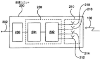
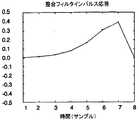
他の(前の実施形態と組み合わせることができる)一実施形態においては、間隔を決定するための手段は、複数の受信エレメントで受信された信号に整合フィルタを適用し、整合フィルタの出力に応じて時間差を決定するように動作する。好ましくは、整合フィルタは、整合フィルタ原型でプログラムされ、整合フィルタ原型は、好ましくは、生成されるパルス波形の少なくとも一部に対応し、好ましくは、それを使用して、フィルタ入力がフィルタ原型により近く整合するほど、フィルタ出力が大きくなるように、フィルタ係数を設定する。 In another embodiment (which can be combined with the previous embodiment), the means for determining the interval applies a matched filter to the signals received by the plurality of receiving elements, depending on the output of the matched filter And operate to determine the time difference. Preferably, the matched filter is programmed with a matched filter prototype, and the matched filter prototype preferably corresponds to at least a portion of the generated pulse waveform, and preferably is used to filter input by the filter prototype. The filter coefficient is set so that the filter output increases as the matching becomes closer.
(一般に能動追跡装置によって放射される信号などの)ブロードバンド信号のコンテキストでは理論的に適切ではないが、それにもかかわらず整合フィルタが、有用な性能レベルを実現したという、驚くべき発見がなされた。また、この重要な特徴は、独立して提供される。 Although not theoretically appropriate in the context of broadband signals (typically signals emitted by active tracking devices), a surprising discovery has been made that nevertheless the matched filter has achieved a useful level of performance. This important feature is also provided independently.
したがって、本発明の関係する一態様においては、物体に関する位置情報を決定するための機器であって、複数の受信エレメントを含む、受信するための手段と、受信エレメントで受信された信号を検出し、受信信号を表す出力信号を生成するための検出手段と、複数の受信エレメントによって受信される信号間の間隔を検出するように整合フィルタを適用し、それによって物体の角位置を決定するように動作可能な処理手段とを含む機器が提供される。 Accordingly, in a related aspect of the present invention, an apparatus for determining position information about an object, comprising means for receiving, including a plurality of receiving elements, and a signal received by the receiving elements are detected. Applying a matched filter to detect the interval between the signals received by the plurality of receiving elements and detection means for generating an output signal representative of the received signal, thereby determining the angular position of the object An apparatus is provided that includes operable processing means.
密接に関係する一態様においては、物体に関する位置情報を決定するための機器であって、複数の受信エレメントを含む受信手段と、整合フィルタを含み、受信エレメントのうちの1つによって受信されたある信号と受信エレメントのうちの少なくとも1つの他の受信エレメントによって受信されたその信号またはある信号との間の間隔を検出し、それによって物体の角位置を決定するように動作可能な処理手段とを含む機器が提供される。 In one closely related aspect, an apparatus for determining positional information about an object, comprising receiving means including a plurality of receiving elements and a matched filter, received by one of the receiving elements. Processing means operable to detect an interval between the signal and that signal or one signal received by at least one other receiving element of the receiving elements and thereby determine the angular position of the object; Including equipment is provided.
他の密接に関係する態様によれば、物体に関する位置情報を決定するための機器であって、複数の受信エレメントを含む、受信するための手段と、受信エレメントで受信された信号を検出し、受信信号を表す出力信号を生成するための検出手段と、各受信エレメントごとに、他の任意の受信エレメントで受信される信号から生成される任意の出力信号とは別に、その受信エレメントで受信される信号から生成される出力信号にプロセスを適用し、その結果、その受信エレメントで受信される信号を表すパラメータのそれぞれの値を得るように動作可能な処理手段とを含み、処理手段はさらに、こうして得られたパラメータの値を比較し、その結果、物体に関する位置情報を取得するように動作可能な機器が提供される。 According to another closely related aspect, an apparatus for determining positional information about an object, comprising means for receiving, including a plurality of receiving elements, and detecting a signal received at the receiving element; Detection means for generating an output signal representative of the received signal and, for each receiving element, received by the receiving element separately from any output signal generated from a signal received by any other receiving element. Processing means operable to apply a process to the output signal generated from the signal to obtain a respective value of the parameter representing the signal received at the receiving element, the processing means further comprising: A device is provided that is operable to compare the values of the parameters thus obtained and, as a result, obtain position information about the object.
これらの態様のいずれにおいても、この機器は、例えば遅延線を使用するのではなく、デジタル領域における整合フィルタリングを使用して、角位置を決定することが可能となり得る。 In any of these aspects, the instrument may be able to determine the angular position using matched filtering in the digital domain, for example, rather than using a delay line.
好ましくは、パラメータは、位相および時間のうちの1つ(したがって、位相または時間またはその両方)である。
好ましくは、処理手段によって適用されるプロセスは、信号の特性、または予想される特性に依存する。好ましくは、特性、または予想される特性は、周波数、位相、帯域幅、およびパルス幅のうちの少なくとも1つである。
Preferably, the parameter is one of phase and time (and thus phase and / or time).
Preferably, the process applied by the processing means depends on the characteristics of the signal or the expected characteristics. Preferably, the characteristic or expected characteristic is at least one of frequency, phase, bandwidth, and pulse width.
好ましくは、処理手段によって適用されるプロセスは、物体の特性、または予想される特性に依存し、好ましくは、受信手段からの物体の距離、または予想される距離に依存する。 Preferably, the process applied by the processing means depends on the characteristics of the object or on the expected characteristics, preferably on the distance of the object from the receiving means or on the expected distance.
好ましくは、この機器は、複数の可能なプロセスから、処理手段によって適用されるプロセスを選択するように適合された選択手段をさらに含む。このプロセスは、例えば信号自体の周波数範囲に最適であるように適合させることのできるフィルタリングでよい。 Preferably, the apparatus further comprises selection means adapted to select a process applied by the processing means from a plurality of possible processes. This process may be, for example, filtering that can be adapted to be optimal for the frequency range of the signal itself.
好ましくは、この機器は、複数組のプロセスデータを記憶するための手段を含み、選択手段は、複数組のプロセスデータから1組のプロセスデータを選択し、それにより処理手段によって適用されるプロセスを選択するように適合される。 Preferably, the apparatus includes means for storing a plurality of sets of process data, and the selecting means selects a set of process data from the plurality of sets of process data, and thereby the process applied by the processing means. Adapted to choose.
好ましくは、この機器は、パラメータの、少なくとも1つのあらかじめ取得された値に応じて、かつ/または物体に関する、あらかじめ取得された位置情報に応じて、処理手段によって適用されるプロセスを変更するための手段をさらに含む。 Preferably, the device is for changing the process applied by the processing means in accordance with at least one pre-obtained value of the parameter and / or in accordance with pre-obtained position information about the object. Means are further included.
好ましくは、このプロセスは整合フィルタを含む。整合フィルタは、好ましくは、フィルタリングされるパルスの逆応答であり、その複素数を乗算するとデルタ関数が得られる特性をもつ波形で定義される。整合フィルタは、好ましくは、電子的に合成される。 Preferably, the process includes a matched filter. The matched filter is preferably the inverse response of the filtered pulse and is defined by a waveform that has the characteristic of multiplying its complex number to yield a delta function. The matched filter is preferably synthesized electronically.
好ましくは、プロセスは、複数の異なる時間オフセットでフィルタを出力信号に適用すること、およびフィルタからの出力に応じて時間オフセットを選択することを含む。
好ましくは、処理手段の動作は、複数の受信エレメントによって受信された信号の間の間隔を検出するように整合フィルタを適用し、それによって物体の角位置を決定することを含む。
Preferably, the process includes applying a filter to the output signal at a plurality of different time offsets and selecting a time offset in response to the output from the filter.
Preferably, the operation of the processing means includes applying a matched filter to detect intervals between signals received by the plurality of receiving elements, thereby determining the angular position of the object.
好ましくは、この機器は、少なくとも1つの時変信号の形に応じて、および好ましくは少なくとも1つの時変信号の包絡線の形に応じて、整合フィルタを生成するための手段をさらに含む。 Preferably, the apparatus further comprises means for generating a matched filter according to the shape of the at least one time-varying signal and preferably according to the shape of the envelope of the at least one time-varying signal.
好ましくは、生成手段は、少なくとも1つの時変信号の形、または少なくとも1つの時変信号の包絡線を、関数、好ましくは二次関数に合わせるように適合される。
好ましくは、受信手段および検出手段は、その周波数の5%、10%、または20%よりも大きい帯域幅を有する信号を受信し検出するように適合される。
Preferably, the generating means is adapted to fit the shape of the at least one time-varying signal or the envelope of the at least one time-varying signal to a function, preferably a quadratic function.
Preferably, the receiving means and detecting means are adapted to receive and detect signals having a bandwidth greater than 5%, 10% or 20% of their frequency.
好ましくは、各信号は、0.5GHz〜24GHz、好ましくは2GHz〜12GHz、およびより好ましくは5.8GHz〜7.2GHzの特性周波数を有する。
好ましくは、信号はパルス信号である。
Preferably, each signal has a characteristic frequency of 0.5 GHz to 24 GHz, preferably 2 GHz to 12 GHz, and more preferably 5.8 GHz to 7.2 GHz.
Preferably, the signal is a pulse signal.
好ましくは、各パルス信号は、少なくとも5サイクルを含み、好ましくは少なくとも10、20、50、100、または500サイクルを含む。
好ましくは、各パルス信号は、2nsより長い、好ましくは5ns、10ns、20ns、および50nsのうちの少なくとも1つよりも長いパルス長を有する。
Preferably, each pulse signal includes at least 5 cycles, preferably at least 10, 20, 50, 100, or 500 cycles.
Preferably, each pulse signal has a pulse length longer than 2 ns, preferably longer than at least one of 5 ns, 10 ns, 20 ns, and 50 ns.
好ましくは、信号は、2MHz〜20MHz、場合によっては5MHz〜15MHz、場合によっては10.5MHz〜13.5MHzの特性繰返し周波数を有するパルス列を含む。 Preferably, the signal comprises a pulse train having a characteristic repetition frequency of 2 MHz to 20 MHz, possibly 5 MHz to 15 MHz, and possibly 10.5 MHz to 13.5 MHz.
好ましくは、位置情報は、物体の角位置である。
好ましくは、その物体または各物体は、送信機を組み込んだ物体を含むまたは備える。
好ましくは、信号は、物体と関連した送信機によって送信される信号である。
Preferably, the position information is an angular position of the object.
Preferably, the object or each object comprises or comprises an object incorporating a transmitter.
Preferably, the signal is a signal transmitted by a transmitter associated with the object.
好ましくは、物体と関連した送信機によって送信される信号は、超広帯域(UWB)信号である。
(少なくとも)いずれの整合フィルタ態様においても、好ましくは、受信手段および検出手段は、その周波数の5%、10%、20%、30%、または40%よりも大きい帯域幅を有する信号を受信し検出するように適合される。あるいは、受信手段および検出手段は、その周波数の5%未満の帯域幅を有する信号を受信し検出するように適合させることもできる。好ましくは、整合フィルタは、パルスの持続時間よりもかなり小さい、受信パルスの一部分に整合するように適合され、整合部分はほぼシヌソイドである。
Preferably, the signal transmitted by the transmitter associated with the object is an ultra wideband (UWB) signal.
In (at least) any matched filter aspect, preferably the receiving means and the detecting means receive a signal having a bandwidth greater than 5%, 10%, 20%, 30%, or 40% of its frequency. Adapted to detect. Alternatively, the receiving means and the detecting means can be adapted to receive and detect a signal having a bandwidth of less than 5% of its frequency. Preferably, the matched filter is adapted to match a portion of the received pulse that is substantially less than the duration of the pulse, and the matched portion is approximately sinusoidal.
この機器は、物体に向けてプローブ信号を送信するための手段をさらに含み得、受信するための手段は、物体からのプローブ信号の反射を受信するように適合される。
この特徴は、物体に関する位置情報を決定するための機器であって、信号パルスを受信するための手段であって、前記信号パルスが好ましくは超広帯域信号パルスである手段と、受信手段に結合され、物体の角位置をそこから決定することができる出力を生成するための検出手段と、物体に向けてプローブ信号を送信するための手段とを含み、前記受信手段および前記送信手段が、単一のハウジング内に、または共通の基板上に配置され、前記信号パルスが、物体からのプローブ信号の反射および物体に関連した送信機によって送信される信号のうちの1つである機器の形で、独立に提供することもできる。
The apparatus may further include means for transmitting a probe signal toward the object, the means for receiving being adapted to receive a reflection of the probe signal from the object.
This feature is a device for determining position information about an object, means for receiving a signal pulse, said signal pulse being preferably an ultra-wideband signal pulse and coupled to the receiving means Detecting means for generating an output from which the angular position of the object can be determined and means for transmitting a probe signal towards the object, wherein the receiving means and the transmitting means are a single unit In a housing or on a common substrate, wherein the signal pulse is one of the reflection of the probe signal from the object and the signal transmitted by the transmitter associated with the object, It can also be provided independently.
プローブ信号を送信するための手段は、好ましくは、物体と関連した送信機によって送信される信号と異なる信号を送信するように適合される。好ましくは、そのような異なる信号は、周波数、位相、またはパルス波形や関連周波数スペクトルなど他の信号特性において異なる。 The means for transmitting the probe signal is preferably adapted to transmit a signal different from the signal transmitted by the transmitter associated with the object. Preferably, such different signals differ in frequency, phase, or other signal characteristics such as pulse waveform and associated frequency spectrum.
この機器は、プローブ信号を符号化し、それによってそれを物体から受信された信号と区別することができるための手段をさらに含む。好ましくは、符号化するための手段は、物体に関連した送信機によって送信される信号に関して、上記のとおりである。 The instrument further includes means for encoding the probe signal so that it can be distinguished from the signal received from the object. Preferably, the means for encoding is as described above with respect to the signal transmitted by the transmitter associated with the object.
この機器は、好ましくは、プローブ信号によって照射された物体の位置情報を決定するための手段をさらに含む。これにより、この機器の周囲の環境の認識度が高まり得る。好ましくは、そのように決定される位置情報は、送信機を組み込んだ物体に関する上記の位置情報の形のうちの1つの形である。 The instrument preferably further comprises means for determining position information of the object illuminated by the probe signal. Thereby, the recognition degree of the environment around this apparatus may increase. Preferably, the position information so determined is in the form of one of the above-mentioned forms of position information relating to the object incorporating the transmitter.
好ましくは、照射された物体の検出は、放射する物体(すなわち、送信機を組み込んだ物体)の検出と同時に動作可能であるが、あるいは、(例えば、夜において)放射物体の検出が使用不可でありながら動作可能とすることもでき、その逆も同様である。 Preferably, the detection of the illuminated object is operable simultaneously with the detection of the radiating object (ie, the object incorporating the transmitter), or the detection of the radiating object is unusable (eg at night). It can also be operable, but vice versa.
好ましくは(いずれの態様においても)、この機器は、照射された物体の位置情報を、少なくとも1つの既知の物体に関する位置情報と比較し、それによって異常な物体を識別することができるための手段をさらに含む。そのような異常な物体は、例えば、必要な送信タグを有していない、侵入者である可能性がある。 Preferably (in any aspect), the apparatus is a means for comparing position information of the illuminated object with position information relating to at least one known object, thereby identifying an abnormal object Further included. Such an abnormal object may be, for example, an intruder who does not have the necessary transmission tags.
好ましくは、「既知の物体」には、この機器によって検出されたいずれかまたはすべての物体、事前プログラムされまたは前の測定から推定された(この機器の付近の構造的特徴などの)基準物体、および追加の物体を含むことも含まないこともある、事前プログラムされまたは測定された検出区域が含まれる。 Preferably, the “known object” includes any or all objects detected by the instrument, reference objects (such as structural features near the instrument) pre-programmed or estimated from previous measurements, And pre-programmed or measured detection areas that may or may not include additional objects.
この機器は、好ましくは、比較の結果に応じて警報信号を生成するための手段をさらに含む。これにより、最小限の改変で、侵入検出システムを提供して、物体追跡システムを補って完全にすることができる。好ましくは、その物体または各物体は、送信機を組み込んだ物体を含み、好ましくは、基準物体は、複数の既知の物体および/またはこの機器によって検出された物体を含む。 The instrument preferably further includes means for generating an alarm signal in response to the result of the comparison. This can provide an intrusion detection system with minimal modification to complement the object tracking system. Preferably, the object or each object includes an object incorporating a transmitter, and preferably the reference object includes a plurality of known objects and / or objects detected by the instrument.
したがって、本発明の他の一態様においては、信号を送信する物体を求めて検出体積内を検索するための機器であって、複数の受信エレメントを含むアレイと、受信エレメントに到着する信号を検出し、受信信号を表す出力信号を生成するための検出手段と、複数の受信エレメントで受信される信号の間の間隔を決定し、それによって物体の存在およびその角位置を決定することができるための処理手段とを含む機器が提供される。 Accordingly, in another aspect of the invention, an apparatus for searching within a detection volume for an object that transmits a signal, wherein the array includes a plurality of receiving elements and a signal arriving at the receiving element is detected. The distance between the detection means for generating an output signal representative of the received signal and the signals received by the plurality of receiving elements can be determined, thereby determining the presence of the object and its angular position The processing means is provided.
密接に関係する一態様においては、信号を送信する物体を求めて検出体積内を検索するための機器であって、複数の受信エレメントを含むアレイと、受信エレメントに到着する所与の距離ゲートからの少なくとも1つの信号を検出し、少なくとも1つの受信信号を表す出力信号を生成するための検出手段と、距離ゲートを変化させるための手段と、複数の受信エレメントのうちの1つで受信される少なくとも1つの信号と複数の受信エレメントの他の受信エレメントまたは他の各受信エレメントで受信される少なくとも1つの信号との間の間隔を決定し、それにより、物体からの信号の送信が機器と同期化されているかどうかに関係なく、物体の存在およびその角位置を決定することができるための処理手段とを含む機器が提供される。 In one closely related aspect, an apparatus for searching within a detection volume for an object transmitting a signal from an array including a plurality of receiving elements and a given distance gate arriving at the receiving elements. Detection means for detecting at least one signal and generating an output signal representative of at least one received signal, means for changing the distance gate, and received by one of the plurality of receiving elements Determining an interval between at least one signal and at least one signal received by another receiving element or each other receiving element of the plurality of receiving elements, whereby the transmission of the signal from the object is synchronized with the device And a processing means for determining the presence of the object and its angular position, whether or not
したがって、ロックされていないレーダ中を検索するシステムを実施することができる。
好ましくは、送信信号を生成するのに使用されない、検出手段と結合された受信機クロックをさらに含む。
Therefore, it is possible to implement a system for searching in an unlocked radar.
Preferably, it further includes a receiver clock coupled to the detection means that is not used to generate the transmission signal.
好ましくは、検出手段は、所与の距離ゲート内の信号を検出するように動作可能であり、この機器は、距離ゲートを変化させ、それによってこの機器と同期化されていない物体を検出することができるための手段をさらに含む。 Preferably, the detection means is operable to detect a signal within a given distance gate, and the device changes the distance gate, thereby detecting an object that is not synchronized with the device. And further includes means for enabling.
好ましくは、物体がこの機器と同期化されていないことは、物体とこの機器が非同期であることを意味する。本発明では「非同期」という語は、好ましくは、具体的には(一方から他方へのパルスの送信など)物体間の対話に関して、共通のタイミングすなわち同期が存在しないことを意味する。この場合、対話に関連するエレメント(例えば、送信機および受信機)は、同じタイミング信号によって駆動されない。好ましくは、「非同期」は、そのようなタイミング信号間の任意の位相差を意味するが、周波数または(同様に)期間における任意の差も意味し得る。 Preferably, the object is not synchronized with the device means that the object and the device are asynchronous. In the context of the present invention, the term “asynchronous” preferably means that there is no common timing or synchronization, in particular for the interaction between objects (such as transmission of pulses from one to the other). In this case, the elements associated with the interaction (eg, transmitter and receiver) are not driven by the same timing signal. Preferably, “asynchronous” means any phase difference between such timing signals, but can also mean any difference in frequency or (similarly) duration.
本発明では、受動レーダシステム(すなわち、受信機がプローブパルスを送信するシステム)のコンテキストにおける「距離ゲート」という語は、好ましくは、ある時間範囲が経過した後、パルスが進むことになる距離によって規定される空間領域を意味する。例えば、従来技術の受動レーダシステムは、パルスの送信後、所定の遅延で受信機の測定値を読み取るが、例えば、dc/2、(T+d)c/2、(2T+d)c/2などに位置する固定の距離ゲートを有する。ここで、cは光の速度、dはパルスの送信と受信信号のサンプリングとの間の遅延、およびTは、連続パルス間の遅延(一般にdよりもはるかに大きい)である。 In the context of the present invention, the term “distance gate” in the context of a passive radar system (ie a system in which the receiver transmits probe pulses) preferably refers to the distance that the pulse will travel after a certain time range. Means a defined spatial region. For example, a prior art passive radar system reads a receiver measurement with a predetermined delay after transmitting a pulse, but is located at, for example, dc / 2, (T + d) c / 2, (2T + d) c / 2, etc. With a fixed distance gate. Where c is the speed of light, d is the delay between sending the pulse and sampling the received signal, and T is the delay between successive pulses (generally much larger than d).
受信機および送信機が「ロックされていない」(すなわち、同期化されていない)、非同期信号のコンテキストにおいては、「距離ゲート」という語は、好ましくは、受信機クロックからの所与のオフセットで受信機によって検出されることになる、送信機の空間および位相オフセットの組合せを指す。したがって、パルス繰返し時間P(すなわち、送信パルス間で経過する時間)における所与のオフセットdの場合、d/P×360°の受信機に相対的な位相を有する、n(P+d)cの距離にある送信機は、理論的に距離ゲート内に収まることになる。ここで、nは整数、およびcは光の速度である。基本的に距離ゲートは、同期ゲートおよび非同期ゲートのどちらでも同じ方法で生成されるが、非同期のケースでは、距離ゲートはより抽象的な特性であることが注目される。 In the context of asynchronous signals where the receiver and transmitter are “unlocked” (ie, not synchronized), the term “distance gate” is preferably at a given offset from the receiver clock. Refers to the combination of transmitter spatial and phase offset that will be detected by the receiver. Thus, for a given offset d in pulse repetition time P (ie, the time that elapses between transmitted pulses), the distance of n (P + d) c with a phase relative to the receiver of d / P × 360 ° The transmitter in the theory would fit within the distance gate. Here, n is an integer, and c is the speed of light. It is noted that basically the distance gate is generated in the same way for both synchronous and asynchronous gates, but in the asynchronous case the distance gate is a more abstract property.
上記から、固定の距離ゲートが使用された場合、この機器からの距離が変化しない物体および受信機に相対的な位相が変化しない物体は、どちらも検出されないことがわかる。また、この重要な特徴は、独立して提供される。 From the above, it can be seen that when a fixed distance gate is used, neither an object whose distance from the device does not change nor an object whose phase relative to the receiver does not change is detected. This important feature is also provided independently.
好ましくは、この機器は、この機器を同じ機器(すなわち、好ましくは上記の機器)で較正するための手段をさらに含む。これにより、この機器の検出精度を高めることができる。また、この特徴は、独立して提供される。 Preferably, the instrument further comprises means for calibrating the instrument with the same instrument (ie preferably the instrument described above). Thereby, the detection accuracy of this apparatus can be improved. This feature is also provided independently.
したがって、本発明の関係する一態様においては、送信機を組み込んだ物体に関する位置情報を決定するための機器であって、物体における送信機から送信された信号を受信するための手段と、受信手段に結合され、受信手段によって受信された信号を検出し、受信信号を表す出力信号を生成するための検出手段と、この機器を同じ機器で較正するための手段とを含む機器が提供される。 Accordingly, in a related aspect of the present invention, an apparatus for determining position information relating to an object incorporating a transmitter, the means for receiving a signal transmitted from the transmitter in the object, and a receiving means An instrument is provided that includes detection means for detecting a signal received by the receiving means and generating an output signal representative of the received signal, and means for calibrating the instrument with the same instrument.
較正手段は、基準送信機からの信号を受信し、受信基準信号を表す信号を出力するように適合させることができる。受信基準信号を表す信号を提供することにより、この機器は、そのような2つの機器間の信号の受信の相対タイミングなど、物体から受信される信号の追加の特性を、外部エージェントが推定することを可能にできる。この特徴は、受信ユニットに共通クロックを提供せずに、そのような相対タイミングを決定させることを可能にできるので、有利である。 The calibration means can be adapted to receive the signal from the reference transmitter and output a signal representative of the received reference signal. By providing a signal representative of the received reference signal, the device allows the external agent to estimate additional characteristics of the signal received from the object, such as the relative timing of reception of the signal between the two devices. Can be made possible. This feature is advantageous because it can allow such relative timing to be determined without providing a common clock to the receiving unit.
好ましくは、較正手段は、物体に関連する送信機からの信号の到着時間と基準送信機からの信号の到着時間との間のタイミング差を表す信号を出力するように適合される。これにより、較正を実施するのを補助することができる。 Preferably, the calibration means is adapted to output a signal representative of the timing difference between the arrival time of the signal from the transmitter associated with the object and the arrival time of the signal from the reference transmitter. This can assist in performing calibration.
あるいは、またはさらに、較正手段は、共通クロック信号に応じて検出手段をトリガするための手段を含むことができる。そのようなクロック信号は、比較的容易に生成することができ、この機器から信号データを出力する目的で既に存在する接続を介して送信することができる。好ましくは、トリガ手段は、共通クロック信号の受信からの所定の時間オフセットで受信信号の走査を開始するように適合される。 Alternatively or additionally, the calibration means can include means for triggering the detection means in response to the common clock signal. Such a clock signal can be generated relatively easily and can be transmitted over an existing connection for the purpose of outputting signal data from this device. Preferably, the trigger means is adapted to start scanning the received signal at a predetermined time offset from reception of the common clock signal.
好ましくは、この機器は、物体をさらに含む(物体自体を組み込む)。これにより、スタンドアロンシステムを作成することができる。この機器は、好ましくは、複数の角位置測定に応じて物体の変位を決定するための手段をさらに含み、好ましくは、遠隔の位置決定機器から角位置情報を受信するための手段を含む。 Preferably, the device further includes an object (incorporates the object itself). Thereby, a stand-alone system can be created. The instrument preferably further includes means for determining the displacement of the object in response to the plurality of angular position measurements, and preferably includes means for receiving angular position information from the remote position determining instrument.
本発明の他の一態様においては、送信機を組み込んだ物体を位置決定するためのシステムであって、上記の少なくとも1つの機器と、複数の決定された角位置に応じて物体の変位を決定するための手段とを含むシステムが提供される。 In another aspect of the invention, a system for locating an object incorporating a transmitter, wherein the displacement of the object is determined in accordance with the at least one device and a plurality of determined angular positions. And a means for providing a system.
密接に関係する一態様においては、送信機を組み込んだ物体を位置決定するためのシステムであって、物体から信号を受信し、受信信号を表す信号を出力するための手段を含む少なくとも1つの機器と、その機器または各機器に対する物体の角位置を決定するための手段と、決定された角位置情報に応じて物体の変位を決定するための処理手段とを含むシステムが提供される。好ましくは、その機器または各機器は、上記の他の任意の機器の、任意のまたはすべての互換性のある特徴を含んでいる。 In one closely related aspect, a system for locating an object incorporating a transmitter, comprising at least one device comprising means for receiving a signal from the object and outputting a signal representative of the received signal And a means for determining the angular position of the object relative to the device or each device, and a processing means for determining the displacement of the object in response to the determined angular position information. Preferably, the device or each device includes any or all compatible features of any other device described above.
好ましくは、システムは、好ましくは4未満、および好ましくは3未満の、複数の機器を含む。機器の数は、好ましくは、円弧近似距離方法に基づいた等価システムで必要とされるものよりも、少なくとも1つ少ない。 Preferably, the system includes a plurality of devices, preferably less than 4, and preferably less than 3. The number of devices is preferably at least one less than that required in an equivalent system based on the arc approximate distance method.
好ましくは、受信するための手段または各手段は非同期であり、好ましくは、このシステムは、少なくとも1つの物体および関連する送信機をさらに含む。
本発明の他の態様においては、上記の機器を含む車両が提供される。
Preferably, the means for receiving or each means is asynchronous and preferably the system further comprises at least one object and an associated transmitter.
In another aspect of the present invention, a vehicle including the above device is provided.
本発明のさらに他の態様においては、減衰媒体を介して伝送される信号を受信し検出するように動作可能な、上記の機器が提供される。好ましくは、この機器は、壁または床を通して、壁または床内で、地下から、あるいは受信するための手段と物体との間の見通しコンタクトなしで、信号を受信し検出するように動作可能である。 In yet another aspect of the invention, an apparatus as described above is provided that is operable to receive and detect signals transmitted over an attenuation medium. Preferably, the device is operable to receive and detect signals through the wall or floor, within the wall or floor, from the basement, or without line-of-sight contact between the means for receiving and the object. .
本発明の他の態様においては、位置決め信号を送信するための機器であって、信号を生成するための手段と、信号を送信するための手段とを含み、信号生成手段が、上記の機器で使用するのに適した信号を生成するように適合される機器が提供される。 In another aspect of the present invention, an apparatus for transmitting a positioning signal includes means for generating a signal and means for transmitting a signal, wherein the signal generating means is the above-described apparatus. An apparatus is provided that is adapted to generate a signal suitable for use.
好ましくは、信号生成手段は、特性繰返し周波数を有するパルス列を含む信号を生成するように適合される。特性繰返し周波数は、2MHz〜20MHz、好ましくは5MHz〜15MHz、およびより好ましくは10.5MHz〜13.5MHzでよい。パルスは、0.5GHz〜24GHz、好ましくは2GHz〜12GHz、およびより好ましくは5.8GHz〜7.2GHzの特性周波数を有してよい。 Preferably, the signal generating means is adapted to generate a signal including a pulse train having a characteristic repetition frequency. The characteristic repetition frequency may be 2 MHz to 20 MHz, preferably 5 MHz to 15 MHz, and more preferably 10.5 MHz to 13.5 MHz. The pulse may have a characteristic frequency of 0.5 GHz to 24 GHz, preferably 2 GHz to 12 GHz, and more preferably 5.8 GHz to 7.2 GHz.
信号生成手段は、区別入力に応じて、生成される信号の固有特性を変化させるように適合させることができる。固有特性は、信号のパルス繰返し周波数でよく、あるいはパルス位置変調特性でもよい。この機器は、信号を時分割多重化する手段をさらに含むことができる。 The signal generating means can be adapted to change the inherent characteristics of the generated signal in response to the discrimination input. The intrinsic characteristic may be a pulse repetition frequency of the signal or a pulse position modulation characteristic. The apparatus can further include means for time division multiplexing the signal.
信号生成手段は、好ましくは、その周波数の5%、10%、または20%よりも大きい帯域幅を有する信号を生成するように適合される。
本発明の他の態様においては、物体に関する位置情報を決定する方法であって、信号を生成すること、物体から受信機器に信号を送信すること、受信機器で信号を検出すること、および受信機器に相対的な物体の角位置をそこから決定することができる出力を生成することを含む方法が提供される。
The signal generating means is preferably adapted to generate a signal having a bandwidth greater than 5%, 10% or 20% of its frequency.
In another aspect of the invention, a method for determining positional information about an object, comprising generating a signal, transmitting a signal from the object to a receiving device, detecting a signal at the receiving device, and receiving device A method is provided that includes generating an output from which an angular position of the object relative to can be determined.
密接に関係する一態様においては、送信機を組み込んだ物体に関する位置情報を決定する方法であって、信号パルス、好ましくは超広帯域信号パルスを生成すること、組み込まれた送信機から、単一のハウジング内に、または共通の基板上に配置され、複数の受信エレメントを含む受信機器に信号パルスを送信すること、複数の受信エレメントにおいて受信された信号パルスの相対タイミングを検出すること、および受信機器に相対的な物体の角位置をそこから決定することができる出力を生成することを含む方法が提供される。 In one closely related aspect, a method for determining positional information about an object incorporating a transmitter, comprising generating a signal pulse, preferably an ultra-wideband signal pulse, from an integrated transmitter, a single Transmitting signal pulses to a receiving device that is disposed within a housing or on a common substrate and includes a plurality of receiving elements, detecting relative timing of signal pulses received at the plurality of receiving elements, and receiving devices A method is provided that includes generating an output from which an angular position of the object relative to can be determined.
この方法は、受信機器で信号の検出をトリガすることをさらに含むことができ、トリガすることは、送信信号の生成に無関係である。好ましくは、この方法は、受信トリガ制御信号に応じて、信号の検出をトリガすることをさらに含む。好ましくは、信号の検出は、制御信号によって決定される周波数でトリガされる。より好ましくは、信号は、特性繰返し周波数で生成され、信号の検出は、特性繰返し周波数とは異なるトリガ周波数でトリガされる。 The method can further include triggering detection of a signal at the receiving device, wherein triggering is independent of generation of the transmitted signal. Preferably, the method further includes triggering detection of the signal in response to the reception trigger control signal. Preferably, the detection of the signal is triggered at a frequency determined by the control signal. More preferably, the signal is generated at a characteristic repetition frequency and detection of the signal is triggered at a trigger frequency that is different from the characteristic repetition frequency.
トリガ周波数Ftrigは、好ましくは、(Fcr/n)+Fdiffによって決まり、ここでFcrは特性繰返し周波数、nは整数の分周比、およびFdiffは走査速度である。nは1より大きくてよく、好ましくは2、3、4、または5より大きい。Fdiffは、好ましくは非ゼロであり、好ましくはFcrの振幅の5%、2%、または1%未満、およびより好ましくはFcrの振幅の0.5%未満である。 The trigger frequency F trig is preferably determined by (F cr / n) + F diff , where F cr is the characteristic repetition frequency, n is an integer division ratio, and F diff is the scan speed. n may be greater than 1, preferably greater than 2, 3, 4, or 5. F diff is preferably non-zero, preferably 5% of the amplitude of F cr, less than 2%, or less than 1%, and more preferably 0.5% of the amplitude F cr.
この方法は、好ましくは、複数の受信エレメントで信号を受信すること、および複数の場所で受信される信号の相対タイミングを検出し、それによって受信機器に相対的な物体の角位置を決定することができることをさらに含む。また、この方法は、好ましくは、受信機器で受信された信号を表す複数の信号を出力することもさらに含む。この方法は、受信機器で制御信号を受信することをさらに含んでよく、物体から受信された信号を処理して、物体に関する位置情報を決定することをさらに含んでもよい。 The method preferably receives signals at multiple receiving elements and detects the relative timing of signals received at multiple locations, thereby determining the angular position of the object relative to the receiving device. It further includes being able to. The method also preferably further includes outputting a plurality of signals representing signals received at the receiving device. The method may further include receiving a control signal at the receiving device, and may further include processing a signal received from the object to determine position information about the object.
受信信号を処理するステップは、追加の角位置と共に信号を処理し、その結果、受信機器に相対的な物体の変位を決定することを含むことができる。この方法は、好ましくは、受信機器で受信された複数の信号間のタイミング差を計算すること、および複数の信号のうちの少なくとも2つの信号間のタイミング差に応じて角位置を決定することをさらに含む。 Processing the received signal may include processing the signal along with the additional angular position, so that the displacement of the object relative to the receiving device is determined. The method preferably includes calculating a timing difference between a plurality of signals received at the receiving device, and determining an angular position according to the timing difference between at least two signals of the plurality of signals. In addition.
この方法は、物体の擬似距離を決定することをさらに含むことができる。好ましくは、擬似距離を決定するステップは、受信信号の振幅を決定すること、および振幅に応じて擬似距離を決定することを含む。この方法は、物体の変位を表す信号を出力することをさらに含むことができる。 The method can further include determining a pseudorange of the object. Preferably, the step of determining the pseudorange includes determining the amplitude of the received signal and determining the pseudorange according to the amplitude. The method can further include outputting a signal representative of the displacement of the object.
好ましくは、信号を生成するステップは、特性パルス周波数を有するパルス列を生成することを含む。この方法は、受信機器で受信パルス列を表す出力を出力することをさらに含んでよく、この方法は、受信パルスの波形を表す信号を出力することをさらに含んでもよい。 Preferably, the step of generating a signal includes generating a pulse train having a characteristic pulse frequency. The method may further include outputting an output representative of the received pulse train at the receiving device, and the method may further include outputting a signal representative of the waveform of the received pulse.
特性パルス周波数は、2MHz〜20MHz、好ましくは5MHz〜15MHz、およびより好ましくは10.5MHz〜13.5MHzでよい。
この方法は、好ましくは、受信パルス列をサンプリングすること、および特性パルス周波数に関する特性サンプリング周波数を有する出力を生成することをさらに含む。出力サンプリング周波数は、特性パルス周波数よりも低くすることができる。出力サンプリング周波数は、5kHz〜100kHz、好ましくは25kHz〜90kHz、およびより好ましくは60kHz〜85kHzでよい。
The characteristic pulse frequency may be 2 MHz to 20 MHz, preferably 5 MHz to 15 MHz, and more preferably 10.5 MHz to 13.5 MHz.
The method preferably further includes sampling the received pulse train and generating an output having a characteristic sampling frequency with respect to the characteristic pulse frequency. The output sampling frequency can be lower than the characteristic pulse frequency. The output sampling frequency may be 5 kHz to 100 kHz, preferably 25 kHz to 90 kHz, and more preferably 60 kHz to 85 kHz.
好ましくは、実質上所与の複数の特性パルス周波数で入力サンプリングクロック信号を生成すること、出力サンプリング周波数で出力サンプリングクロック信号を生成すること、および入力サンプリングクロック信号を受信し次第、信号をサンプリングし、出力サンプリングクロック信号を受信し次第、サンプル出力を生成することをさらに含む。この方法は、好ましくは、前の出力サンプリングクロック信号以降にとられた入力サンプルの平均としてサンプル出力を生成することをさらに含み、この方法は、サンプル出力が生成された後、入力サンプリングクロックの位相を所定の量だけ進めることをさらに含んでもよい。 Preferably, generating the input sampling clock signal at substantially a plurality of characteristic pulse frequencies, generating the output sampling clock signal at the output sampling frequency, and sampling the signal upon receipt of the input sampling clock signal , Further comprising generating a sample output upon receipt of the output sampling clock signal. The method preferably further includes generating the sample output as an average of input samples taken since the previous output sampling clock signal, the method after the sample output is generated, the phase of the input sampling clock May be further advanced by a predetermined amount.
この方法は、好ましくは、物体で送信される信号と少なくとも1つの他の信号とを受信ユニットで区別することをさらに含む。
本発明の関係する一態様においては、物体に関する位置情報を決定する方法であって、物体に関連する送信機を含む複数の送信機によって送信される複数の信号を受信すること、識別情報に応じて物体において送信される信号と任意の追加の受信信号とを区別すること、および区別された信号に応じて物体の角位置を決定し、それによって物体に関する位置情報を決定することができることを含む方法が提供される。
The method preferably further comprises distinguishing at the receiving unit a signal transmitted on the object and at least one other signal.
In a related aspect of the invention, a method for determining position information about an object, comprising receiving a plurality of signals transmitted by a plurality of transmitters including a transmitter associated with the object, in response to identification information Discriminating between signals transmitted at the object and any additional received signals and determining the angular position of the object in response to the distinguished signal, thereby determining position information about the object A method is provided.
密接に関係する一態様においては、送信機を組み込んだ物体に関する位置情報を決定する方法であって、各信号が複数の送信機および組み込まれた送信機を含む複数の送信機のうちのそれぞれの送信機によって送信される、複数の信号を受信すること、および組み込まれた送信機によって送信される信号のパルス繰返し周波数に応じて、組み込まれた送信機によって送信される受信信号と任意の追加の受信信号とを区別することを含み、組み込まれた送信機によって送信される受信信号が、好ましくは少なくとも1つの超広帯域パルスを含む方法が提供される。 In one closely related aspect, a method for determining positional information about an object incorporating a transmitter, each signal of each of a plurality of transmitters including a plurality of transmitters and an embedded transmitter. Depending on the pulse repetition frequency of the signal transmitted by the embedded transmitter and the signal transmitted by the embedded transmitter, any additional signals and any additional signals transmitted by the embedded transmitter A method is provided that includes distinguishing from a received signal, wherein the received signal transmitted by an embedded transmitter preferably includes at least one ultra-wideband pulse.
区別するステップは、好ましくは、信号の固有特性に応じて区別することを含む。固有特性は、信号のパルス繰返し周波数でよく、固有特性は、パルス位置変調特性でもよく、信号は、時分割多重化することができる。 The step of distinguishing preferably includes distinguishing according to the intrinsic characteristics of the signal. The characteristic may be the pulse repetition frequency of the signal, the characteristic may be a pulse position modulation characteristic, and the signal may be time division multiplexed.
好ましくは、この方法は、検出クロックに応じて信号を検出すること、および選択された信号周波数に応じて検出クロックを設定し、それによって選択された信号周波数を有する信号が優先的に検出されることをさらに含む。この方法は、好ましくは、選択された信号周波数と受信信号との間の周波数誤差を検出すること、および周波数誤差を補償することをさらに含む。周波数誤差を検出するステップは、連続パルスのピークに対応する受信信号中の連続ピーク間の間隔に応じて信号周波数を推定すること、および推定信号周波数を検出周波数と比較することを含むことができる。周波数誤差を検出するステップはまた、あるいは代わりに、連続したサンプルの位相差に応じて推定信号周波数を計算すること、および推定信号周波数を検出周波数と比較することを含むこともできる。周波数誤差を補償するステップは、推定周波数誤差によってもたらされる、予想される信号の形を表す整合フィルタ原型を作成することを含む。 Preferably, the method detects the signal according to the detection clock and sets the detection clock according to the selected signal frequency, whereby a signal having the selected signal frequency is detected preferentially. In addition. The method preferably further includes detecting a frequency error between the selected signal frequency and the received signal and compensating for the frequency error. Detecting the frequency error can include estimating the signal frequency as a function of the interval between successive peaks in the received signal corresponding to the peak of the continuous pulse, and comparing the estimated signal frequency to the detected frequency. . The step of detecting the frequency error can also or alternatively include calculating an estimated signal frequency in response to the phase difference of successive samples and comparing the estimated signal frequency to the detected frequency. Compensating the frequency error includes creating a matched filter prototype that represents the expected signal shape caused by the estimated frequency error.
この方法は、好ましくは、複数の場所における信号の受信の間隔を決定し、それによって物体の角位置を決定することを可能にすることをさらに含む。間隔を決定するステップは、少なくとも1対の場所で受信される信号を相互相関させること、および相互相関結果に応じて間隔を決定することを含むことができる。あるいは、間隔を決定するステップは、整合フィルタを複数の場所で受信される信号に適用すること、および整合フィルタの出力に応じて時間差を決定することを含むことができる。 The method preferably further includes determining the interval of reception of the signals at the plurality of locations, thereby allowing the angular position of the object to be determined. Determining the interval can include cross-correlating signals received at at least one pair of locations and determining the interval in response to the cross-correlation result. Alternatively, determining the interval can include applying a matched filter to signals received at multiple locations and determining a time difference in response to the output of the matched filter.
本発明の関係する一態様においては、複数の場所で信号を受信すること、受信信号を表す出力信号を生成する場所で受信された信号を検出すること、および複数の場所で受信される信号間の間隔を検出するように整合フィルタを適用し、それによって物体の角位置を決定することを含む方法が提供される。受信信号は、その周波数の5%、10%、または20%よりも大きい帯域幅を有することができる。 In a related aspect of the invention, receiving signals at multiple locations, detecting a signal received at a location that generates an output signal representing the received signal, and between signals received at multiple locations A method is provided that includes applying a matched filter to detect the spacing of the object, thereby determining the angular position of the object. The received signal can have a bandwidth that is greater than 5%, 10%, or 20% of its frequency.
密接に関係する一態様においては、物体に関する位置情報を決定する方法であって、複数の受信エレメントを含む受信機器で信号を受信すること、および受信エレメントのうちの1つでの信号の受信と受信エレメントのうちの少なくとも1つの他の受信エレメントでの信号の受信との間の間隔を検出するように整合フィルタを適用し、それによって物体の角位置を決定することを含む方法が提供される。 In one closely related aspect, a method for determining positional information about an object comprising receiving a signal at a receiving device including a plurality of receiving elements and receiving a signal at one of the receiving elements. A method is provided that includes applying a matched filter to detect an interval between reception of a signal at at least one other receiving element of the receiving elements, thereby determining an angular position of the object. .
この方法が、物体に向けてプローブ信号を送信すること、および物体からのプローブ信号の反射を受信することをさらに含む場合、プローブ信号を送信するステップは、物体で送信される信号と異なる信号を送信することを含むことができる。この方法は、プローブ信号を符号化し、それによってそれを物体から受信された信号と区別することができることをさらに含むことができる。 If the method further includes transmitting a probe signal toward the object and receiving a reflection of the probe signal from the object, the step of transmitting the probe signal is different from the signal transmitted at the object. Sending can be included. The method can further include encoding the probe signal so that it can be distinguished from the signal received from the object.
また、この方法は、プローブ信号によって照射された物体の位置情報を決定することをさらに含むこともできる。好ましくは、この方法は、次に、照射された物体の位置情報を、少なくとも1つの既知の物体に関する位置情報と比較し、それによって異常な物体を識別することができることをさらに含む。この方法は、比較の結果に応じて警報信号を生成することをさらに含むことができる。その物体または各物体は、好ましくは、受信機器で受信される信号を送信する物体を含む。 The method may further include determining position information of an object illuminated by the probe signal. Preferably, the method further comprises that the position information of the illuminated object can then be compared with position information relating to at least one known object, whereby abnormal objects can be identified. The method can further include generating an alarm signal in response to the result of the comparison. The object or each object preferably includes an object that transmits a signal received at the receiving device.
また、本発明は、物体に関する位置情報を決定する方法であって、受信手段および送信手段を、単一のハウジング内に、または共通の基板上に配置すること、送信手段を使用して、物体に向けてプローブ信号を送信すること、物体からのプローブ信号の反射および物体に関連する送信機によって送信される信号のうちの1つであり、好ましくは超広帯域信号パルスである信号パルスを受信手段で受信すること、および受信信号パルスに応じて、物体の角位置をそこから決定することができる出力を生成することを含む方法も提供する。 The present invention is also a method for determining position information about an object, wherein the receiving means and the transmitting means are arranged in a single housing or on a common substrate, using the transmitting means, Means for receiving a signal pulse, preferably one of a signal transmitted by a transmitter associated with the object, preferably a signal transmitted by the transmitter associated with the object, And generating an output from which the angular position of the object can be determined in response to the received signal pulse.
本発明の他の態様においては、信号を送信する物体を求めて検出体積内を検索する方法であって、複数の場所で信号を受信すること、受信信号を表す出力信号を生成する場所に到着する信号を検出すること、および複数の場所で受信される信号の間の間隔を決定し、それによって物体の存在およびその角位置を決定することができることを含む方法が提供される。 In another aspect of the invention, a method for searching within a detection volume for an object to transmit a signal, receiving the signal at multiple locations and arriving at a location that generates an output signal representing the received signal A method is provided that includes detecting a signal to detect and determining an interval between signals received at multiple locations, thereby determining the presence of the object and its angular position.
密接に関係する一態様においては、信号を送信する物体を求めて検出体積内を検索する方法であって、距離ゲートを設定するステップと、少なくとも1つの信号が複数の受信エレメントを含む機器で受信された場合、かかる少なくとも1つの信号を検出するステップと、複数の受信エレメントのうちの1つで受信された少なくとも1つの信号と複数の受信エレメントのうちの他の受信エレメントまたは他の各受信エレメントで受信された少なくとも1つの信号との間の間隔を決定するステップと、距離ゲートを変化させるステップと、検出するステップおよび決定するステップを繰返し、それによって物体からの信号の送信が機器と同期化されているかどうかに関係なく、物体の存在およびその角位置を決定することができるステップとを含む方法が提供される。 In one closely related aspect, a method for searching within a detection volume for an object to transmit a signal, comprising setting a distance gate and receiving at least one signal with an apparatus including a plurality of receiving elements. A step of detecting such at least one signal, and at least one signal received by one of the plurality of receiving elements and another receiving element or each other receiving element of the plurality of receiving elements. Repeating the steps of determining an interval between at least one signal received at, changing the distance gate, detecting and determining, thereby synchronizing the transmission of the signal from the object with the device The presence of an object and its angular position can be determined regardless of whether A method is provided.
この方法は、所与の距離ゲート内の信号を検出すること、および距離ゲートを変化させ、それによって受信機器と同期化されていない物体を検出することができることをさらに含むことができる。 The method can further include detecting a signal within a given distance gate and changing the distance gate, thereby detecting an object that is not synchronized with the receiving device.
この方法は、好ましくは、受信機器を同じ機器で較正することをさらに含む。
本発明の関係する一態様においては、物体に関する位置情報を決定する方法であって、物体で送信された信号を受信機器で検出すること、受信信号を表す出力信号を生成すること、および受信機器を同じ機器で較正することを含む方法が提供される。この方法は、好ましくは、基準送信機から信号を受信すること、および受信基準信号を表す信号を出力することをさらに含む。この方法は、物体において送信される信号の到着時間と基準送信機において送信される信号の到着時間との間のタイミング差を表す信号を出力することをさらに含むことができる。
The method preferably further includes calibrating the receiving device with the same device.
In a related aspect of the present invention, a method for determining position information about an object, wherein a signal transmitted by the object is detected by a receiving device, an output signal representing the received signal is generated, and the receiving device Are calibrated with the same instrument. The method preferably further includes receiving a signal from the reference transmitter and outputting a signal representative of the received reference signal. The method can further include outputting a signal representative of a timing difference between the arrival time of the signal transmitted at the object and the arrival time of the signal transmitted at the reference transmitter.
受信機器を較正するステップは、共通クロック信号に応じて検出手段をトリガすることを含むことができ、そのケースでは、この方法は、共通クロック信号の受信からの所定の時間オフセットで受信信号の走査を開始することをさらに含むことができる。 The step of calibrating the receiving device can include triggering the detection means in response to the common clock signal, in which case the method scans the received signal at a predetermined time offset from the reception of the common clock signal. Can further include initiating.
好ましくは、この方法は、複数の角位置測定に応じて物体の変位を決定することをさらに含む。この方法は、減衰媒体を介して伝送される信号を受信し検出することをさらに含むことができる。 Preferably, the method further comprises determining the displacement of the object in response to the plurality of angular position measurements. The method can further include receiving and detecting a signal transmitted via the attenuating medium.
本発明の他の態様においては、位置決め信号を送信する方法であって、信号を生成すること、および信号を送信することを含み、信号が、上記の機器で使用するのに適している方法が提供される。 In another aspect of the invention, there is a method for transmitting a positioning signal, comprising generating a signal and transmitting the signal, wherein the signal is suitable for use in the device described above. Provided.
本発明のさらに他の態様においては、位置決め信号を送信する方法であって、信号を生成すること、および信号を送信することを含み、信号が、上記の方法で使用するのに適している方法が提供される。 In yet another aspect of the invention, a method for transmitting a positioning signal comprising generating a signal and transmitting a signal, wherein the signal is suitable for use in the above method. Is provided.
この信号は、上記の特性繰返し周波数を有するパルス列を含むことができる。
この方法は、区別入力に応じて生成信号の固有特性を変化させることをさらに含むことができる。固有特性は、上記のとおりとすることができる。この方法は、信号を時分割多重化することをさらに含むことができる。信号帯域は、上記のとおりとすることができる。
This signal may include a pulse train having the characteristic repetition frequency described above.
The method can further include changing the inherent characteristic of the generated signal in response to the discrimination input. The intrinsic property can be as described above. The method can further include time division multiplexing the signal. The signal band can be as described above.
本発明の他の態様においては、上記の機器で使用するのに適した信号が提供される。
本発明の関係する一態様においては、特性パルス周波数を有するパルス列を含む信号であって、特性パルス周波数が、2MHz〜20MHz、好ましくは5MHz〜15MHz、およびより好ましくは10.5MHz〜13.5MHzであり、パルスが、0.5GHz〜24GHz、好ましくは2GHz〜12GHz、およびより好ましくは5.8GHz〜7.2GHzの特性周波数を有する信号が提供される。
In another aspect of the invention, a signal suitable for use with the above-described device is provided.
In one related aspect of the present invention, a signal including a pulse train having a characteristic pulse frequency, wherein the characteristic pulse frequency is 2 MHz to 20 MHz, preferably 5 MHz to 15 MHz, and more preferably 10.5 MHz to 13.5 MHz. There is provided a signal whose pulses have a characteristic frequency of 0.5 GHz to 24 GHz, preferably 2 GHz to 12 GHz, and more preferably 5.8 GHz to 7.2 GHz.
好ましくは、この方法は、区別入力に応じて生成信号の固有特性を変化させることをさらに含む。好ましくは、固有特性は、信号のパルス繰返し周波数である。好ましくは、固有特性は、パルス位置変調特性である。好ましくは、この方法は、信号を時分割多重化することをさらに含む。好ましくは、この信号は、その周波数の5%、10%、または20%よりも大きい帯域幅を有する。 Preferably, the method further includes changing the inherent characteristic of the generated signal in response to the discrimination input. Preferably, the intrinsic characteristic is the pulse repetition frequency of the signal. Preferably, the intrinsic characteristic is a pulse position modulation characteristic. Preferably, the method further comprises time division multiplexing the signal. Preferably, this signal has a bandwidth greater than 5%, 10% or 20% of its frequency.
上記と同様に、信号は、時分割多重化を使用して符号化してよく、パルス位置変調を使用して符号化してもよい。
本発明の他の態様によれば、物体に関する位置情報を決定するためのシステムにおいて使用するための機器であって、システムの受信機によって検出されるパルスシーケンスを送信するための送信機を含み、送信機が、パルスシーケンスの特性を変化させてデータを受信機に送信するように適合される機器が提供される。
As above, the signal may be encoded using time division multiplexing or may be encoded using pulse position modulation.
According to another aspect of the invention, an apparatus for use in a system for determining positional information about an object, comprising a transmitter for transmitting a pulse sequence detected by a receiver of the system, Equipment is provided in which the transmitter is adapted to change the characteristics of the pulse sequence and transmit data to the receiver.
送信機によって放射されるパルスシーケンスの特性を変化させることによって、送信機と受信機の間でデータを送信することが可能となる。
好ましくは、パルスシーケンスの特性を変化させる速度は、パルス周波数よりも大幅に低い。このようにして、メッセージのデータ速度は、システム自体の無線周波数よりもはるかに低くすることができる。
By changing the characteristics of the pulse sequence emitted by the transmitter, it is possible to transmit data between the transmitter and the receiver.
Preferably, the rate at which the characteristics of the pulse sequence are changed is significantly lower than the pulse frequency. In this way, the data rate of the message can be much lower than the system's own radio frequency.
送信機は、パルスシーケンスのパルス繰返し周波数(PRF)を変化させるように適合させることができる。例えば、2つのパルス繰返し周波数を使用することにより、「0」または「1」を送信機によって送信することができる。PRFは、好ましくは、擬似ランダムに変化させる。複数の送信機が存在し、干渉を避けるためにそれぞれが異なるPRFをもつ場合、変調は、各送信機ごとに異なるようにしてよく、変調の帯域幅は、各PRFチャネルの周波数帯域よりも小さくてよい。 The transmitter can be adapted to change the pulse repetition frequency (PRF) of the pulse sequence. For example, by using two pulse repetition frequencies, “0” or “1” can be transmitted by the transmitter. The PRF is preferably changed pseudo-randomly. If there are multiple transmitters and each has a different PRF to avoid interference, the modulation may be different for each transmitter, and the modulation bandwidth is smaller than the frequency band of each PRF channel. It's okay.
パルスシーケンスは、周期的に中断されてよい。受信機で中断のパターンを分析することにより、送信機によって送信される情報を決定することができる。例えば、送信は、特定の符号に対応する所定の期間、オンおよびオフに切り換えることができる。 The pulse sequence may be interrupted periodically. By analyzing the interruption pattern at the receiver, the information transmitted by the transmitter can be determined. For example, transmission can be switched on and off for a predetermined period corresponding to a particular code.
したがって、受信機で受信されるパルスから決定することのできる位置情報に加えて、パルスシーケンスの特性の変化を分析することにより、送信機によって送信される追加の情報を決定することもできる。 Thus, in addition to position information that can be determined from the pulses received at the receiver, additional information transmitted by the transmitter can also be determined by analyzing changes in the characteristics of the pulse sequence.
このようにして、符号化されたメッセージを、送信機によって送信することができる。
データ送信は、好ましくは、PRF変調によって行われる。これは、例えば、複数の送信機を区別するために使用することができる。各送信機は、この方法により、送信機を識別する情報を含む情報を送信することができる。この機構は、一般に、送信機と受信機システムの間でデータを送信するために使用することができる。
In this way, the encoded message can be transmitted by the transmitter.
Data transmission is preferably done by PRF modulation. This can be used, for example, to distinguish multiple transmitters. Each transmitter can transmit information including information for identifying the transmitter by this method. This mechanism can generally be used to transmit data between a transmitter and a receiver system.
送信機は、物体と関連付けることができる。このようにして、物体に関する位置情報ならびに追加情報を、送信されるパルスシーケンスから決定することができる。送信機は、タグ、好ましくは、上記の本発明の態様のいずれかに対応するタグと関連付けることができる。 A transmitter can be associated with an object. In this way, position information about the object as well as additional information can be determined from the transmitted pulse sequence. The transmitter can be associated with a tag, preferably a tag corresponding to any of the above aspects of the invention.
パルスシーケンスは送信データを含み、位置情報を決定するのに使用される送信信号とほぼ同じ周波数で送信することができる。
好ましくは、データを含むパルスシーケンスは、位置情報を決定するためにも使用される。
The pulse sequence includes transmission data and can be transmitted at approximately the same frequency as the transmission signal used to determine position information.
Preferably, a pulse sequence containing data is also used to determine position information.
送信データは、送信機のIDに関する情報を含むことができる。例えば、データは、送信機の識別子を含むことができる。送信機が物体と関連する場合、この情報を使用して、物体を識別することができる。 The transmission data can include information regarding the ID of the transmitter. For example, the data may include a transmitter identifier. If the transmitter is associated with an object, this information can be used to identify the object.
この情報は、送信機と受信機の間で通信を確立するのに使用される識別子を含むことができる。
この機器は、送信機と受信機の間で通信を行うための手段をさらに含むことができる。例えば、この機器は、追加の通信を行うために、例えば送信機システムまたは受信機システムにおいて、別個の無線送信機を含むことができる。
This information can include an identifier used to establish communication between the transmitter and the receiver.
The apparatus can further include means for communicating between the transmitter and the receiver. For example, the device can include a separate wireless transmitter, for example in a transmitter system or a receiver system, for additional communication.
このような通信を使用して、例えば、送信機から、例えば物体に関する追加の情報を送信することができる。代わりに、またはさらに、この通信を使用して、システムがシステム設定を変更できるようにすることができる。例えば、送信機は、物体に関連したタグを含み、通信を使用して、タグ更新レートなどのシステム設定を変更することができる。 Such communication can be used, for example, to transmit additional information, eg, about an object, from a transmitter. Alternatively or additionally, this communication can be used to allow the system to change system settings. For example, the transmitter can include tags associated with the object and use communications to change system settings such as tag update rate.
機器は、パルスシーケンスの送信を行うための、かつ送信機と受信機の間の通信を行うために使用されるコンポーネントを含むことができる。
例えば、位置決定で使用される信号を伝送する場合と、伝達情報を伝送する場合とで伝送周波数が類似または同じである場合、ほぼ同じコンポーネントをどちらの伝送にも使用することができる。これには、システムのサイズと複雑さを大幅に低減させる潜在的な利点がある。
The equipment can include components used to transmit pulse sequences and to communicate between a transmitter and a receiver.
For example, if the transmission frequency is similar or the same when transmitting a signal used for position determination and when transmitting transmission information, almost the same components can be used for both transmissions. This has the potential advantage of significantly reducing the size and complexity of the system.
本発明によれば、物体に関する位置情報を決定するためのシステムで使用される機器であって、物体の位置を決定するのに使用される信号を送信するための送信機を含み、かつ受信機に伝達情報を送信するための送信機をさらに含み、信号を送信するための送信機のコンポーネントが、伝達情報を送信するための送信機と共通である機器が提供される。 In accordance with the present invention, an apparatus used in a system for determining position information about an object, comprising a transmitter for transmitting a signal used to determine the position of the object, and a receiver A device is provided that further includes a transmitter for transmitting the transmission information, wherein a component of the transmitter for transmitting the signal is in common with the transmitter for transmitting the transmission information.
好ましくは、2つ以上のコンポーネントが送信機に共通である。アンテナ、または信号生成回路、またはフロントエンドのいずれか、またはすべてを共通とすることができる。
本発明によれば、物体に関する位置情報を決定するためのシステムで使用される機器であって、物体の位置を決定するのに使用される信号を受信するための受信機を含み、かつ送信機から伝達情報を受信するための受信機をさらに含み、信号を受信するための受信機のコンポーネントが、伝達情報を受信するための受信機と共通である機器が提供される。
Preferably, two or more components are common to the transmitter. Any or all of the antenna, the signal generation circuit, or the front end can be common.
In accordance with the present invention, an apparatus used in a system for determining position information about an object, including a receiver for receiving a signal used to determine the position of the object, and a transmitter An apparatus is provided that further includes a receiver for receiving transmission information from the receiver, wherein a component of the receiver for receiving the signal is in common with the receiver for receiving the transmission information.
好ましくは、2つ以上のコンポーネントが受信機に共通である。アンテナ、または信号受信回路、またはフロントエンドのいずれか、またはすべてを共通コンポーネントとすることができる。 Preferably, two or more components are common to the receiver. Any or all of the antennas, the signal receiving circuit, or the front end can be a common component.
好ましくは、信号および通信は、ほぼ同じ周波数、好ましくは無線周波数である。
好ましくは、信号は、好ましくは、場合によってはパルス繰返し周波数変調によって信号を符号化または変調した、好ましくは物体の、識別子を含む。好ましくは、識別子はMACアドレスである。
Preferably, the signal and communication are about the same frequency, preferably radio frequency.
Preferably, the signal preferably comprises an identifier, preferably of an object, preferably an object encoded or modulated by pulse repetition frequency modulation. Preferably, the identifier is a MAC address.
好ましくは、信号および通信はUWBである。好ましくは、通信では標準通信プロトコルを使用する。そのようなプロトコルの例には現在、DSRCおよびIEEE 802.11Aが含まれる。好ましくは、通信は両方向である。 Preferably, the signal and communication is UWB. Preferably, a standard communication protocol is used for communication. Examples of such protocols currently include DSRC and IEEE 802.11A. Preferably, communication is bi-directional.
上述の機器のいずれにおいても、送信機と受信機の間の距離は、好ましくは100m未満である。
本明細書に記載の技法は、受信機と送信機装置を含めた物体の間の距離がそれほど大きくない場合に、特に有用である。好ましくは、距離は、50m未満、好ましくは20m未満である。
In any of the above devices, the distance between the transmitter and the receiver is preferably less than 100 m.
The techniques described herein are particularly useful when the distance between objects, including the receiver and transmitter device, is not very large. Preferably the distance is less than 50 m, preferably less than 20 m.
この機器は、データを受信し、他の送受信機または受信機の特性を検出し、その特性に応じてそれらにデータを選択的に送信するように適合された送受信機を含むことができる。好ましくは、その特性は位置である。 The apparatus can include a transceiver adapted to receive data, detect characteristics of other transceivers or receivers, and selectively transmit data to them according to the characteristics. Preferably, the characteristic is position.
本発明のこの態様は独立して提供することができ、物体に関する位置情報を決定するためのシステムで使用される機器であって、データを受信し、他の送受信機または受信機の特性を検出し、その特性に応じてそれらにデータを選択的に送信するように適合された送受信機を含む機器が提供される。好ましくは、その特性は位置である。 This aspect of the invention can be provided independently and is a device used in a system for determining position information about an object, receiving data and detecting characteristics of other transceivers or receivers Thus, an apparatus is provided that includes a transceiver adapted to selectively transmit data to them according to their characteristics. Preferably, the characteristic is position.
例えば、高速道路の1車線上の車両に搭載された送受信機は、道路の該当する側の車両とのみ、道路工事に関するデータを送受信することができる。
送信機および/または受信機は、車両に搭載することができる。
For example, a transceiver mounted on a vehicle on one lane of an expressway can transmit and receive data related to road construction only with a vehicle on the corresponding side of the road.
The transmitter and / or receiver can be mounted on a vehicle.
記載の技法は、車両の位置および方位の決定に対して具体的に適用され、それを使用することにより、例えば、車両間、車両から固定の沿道システムに、および/または固定の沿道システムから車両に、情報を転送することもできる。 The described techniques are specifically applied to the determination of the position and orientation of a vehicle and can be used, for example, between vehicles, from a vehicle to a fixed roadside system, and / or from a fixed roadside system to a vehicle. In addition, information can be transferred.
この機器は、車両の特性に関するデータを送信するように適合させることもできる。
例えば、物体が車両であり、車両に送信機が搭載されている場合、送信機は、車両に関する情報、例えば駆動性能、または例えば急ブレーキをかけているとの情報を送信することができる。この情報を、例えばその情報を送信する車両に近い他の車両で使用して、駆動方針、例えばブレーキ方針または事故回避方針を決定することができる。
The device can also be adapted to transmit data relating to vehicle characteristics.
For example, when the object is a vehicle and the transmitter is mounted on the vehicle, the transmitter can transmit information related to the vehicle, for example, driving performance or information indicating that the vehicle is suddenly braked. This information can be used, for example, in other vehicles close to the vehicle transmitting the information to determine a driving policy, such as a braking policy or an accident avoidance policy.
送信機を道路に設置し、受信機を車両に搭載することもできる。車両のレーダシステムは、それによって道路端の場所を決定することができ、この情報を使用して、車両の駆動方針を変更することができる。 A transmitter can be installed on the road and a receiver can be mounted on the vehicle. The radar system of the vehicle can thereby determine the location of the road edge, and this information can be used to change the driving policy of the vehicle.
この機器は、送信機の位置に局部的な特性に関するデータを送信するように適合させることができる。例えば、送信機は、交通状況、天気状況、ローカルラジオ局、などに関する情報を送信することができる。 The device can be adapted to transmit data relating to local characteristics at the transmitter location. For example, the transmitter can transmit information regarding traffic conditions, weather conditions, local radio stations, and the like.
本発明によれば、車両に関する位置情報を決定するのに使用される機器であって、車両の位置を決定するのに使用される信号を受信するための受信機を含み、かつ車両と関連した送信機から、車両の特性に関する情報に関係した伝達情報を受信するための受信機をさらに含み、受信情報を使用して駆動方針を決定するための制御システムをさらに含む機器がさらに提供される。 In accordance with the present invention, an apparatus used to determine position information about a vehicle, including a receiver for receiving a signal used to determine the position of the vehicle and associated with the vehicle Further provided is an apparatus that further includes a receiver for receiving transmission information related to information related to vehicle characteristics from the transmitter, and further includes a control system for determining a drive strategy using the received information.
本発明によれば、送信機が包装品を位置決定するために使用され、送信機が包装品の特性に関するデータを送信するように適合される、上記の機器を含む在庫管理システムであって、その機器が、受信データを使用して商品をどこに格納すべきか、またはいつそれらを取り出すべきかを決定するための制御システムをさらに含む在庫管理システムがさらに提供される。 According to the present invention, an inventory management system comprising the above equipment, wherein a transmitter is used to locate a package and the transmitter is adapted to transmit data relating to the characteristics of the package, An inventory management system is further provided that further includes a control system for the device to use the received data to determine where to store goods and when to retrieve them.
本発明によれば、物体に関する位置情報を決定するための方法であって、パルスシーケンスを生成すること、データを送信するためにパルスシーケンスの特性を変化させること、およびシステムの受信機によって検出されるパルスシーケンスを送信することを含む方法がさらに提供される。 In accordance with the present invention, a method for determining position information about an object comprising: generating a pulse sequence; changing characteristics of a pulse sequence to transmit data; and detected by a receiver of the system. There is further provided a method comprising transmitting a pulse sequence.
本発明によれば、上記の方法を実施するように適用されるコンピュータプログラム製品、およびコンピュータプログラム製品を有形に実施するコンピュータ可読媒体が提供される。 In accordance with the present invention, there is provided a computer program product adapted to perform the above method and a computer readable medium for tangibly implementing the computer program product.
本発明によれば、上記の機器または方法で使用される信号が提供される。
本発明の上記のありとあらゆる態様において、例えば位置情報を決定するための、識別子を伝送するための、および通信するための、いくつかまたはすべての伝送は、超広帯域でよい。
According to the present invention, there is provided a signal used in the above device or method.
In any and all aspects of the invention described above, some or all transmissions, eg, for determining location information, for transmitting identifiers, and for communicating, may be ultra-wideband.
本発明の他の態様においては、上記の任意の方法を実施し、上記の任意の機器を実装するように適合されるコンピュータプログラム製品が提供される。本発明では「コンピュータプログラム製品」という語は、好ましくは、(マイクロプロセッサ、DSP、カスタム集積回路、マイクロコントローラなどの)プロセッサで実行されたときに、該当する方法が実施されるようにする、コンピュータ可読形態のデータを意味する。この語は、好ましくは、(JAVAなどの)インタープリタ言語、(コンパイルされるC++などの)コンパイル言語、および機械語を含む。 In another aspect of the invention, a computer program product adapted to implement any of the above methods and to implement any of the above devices is provided. In the present invention, the term “computer program product” is preferably a computer that, when executed on a processor (such as a microprocessor, DSP, custom integrated circuit, microcontroller, etc.), causes the corresponding method to be performed. It means data in readable form. This word preferably includes interpreted languages (such as JAVA), compiled languages (such as compiled C ++), and machine languages.
本発明の他の態様においては、上記のコンピュータプログラム製品を有形に実施するコンピュータ可読媒体が提供される。
本発明のさらに他の態様においては、上記のコンピュータプログラム製品を有形に実施する信号が提供される。
In another aspect of the present invention, a computer readable medium for tangibly implementing the above computer program product is provided.
In yet another aspect of the invention, a signal for tangibly implementing the above computer program product is provided.
本発明は、実質上、添付の図面に即して本明細書に記載される方法および/または機器を包含する。
本発明の1つの態様における任意の特徴は、任意の適切な組合せで、本発明の他の態様に適用することができる。具体的には、方法の態様は、機器の態様に適用することができ、その逆も同様である。
The invention substantially encompasses the methods and / or apparatus described herein with reference to the accompanying drawings.
Any feature in one aspect of the invention may be applied to other aspects of the invention in any suitable combination. Specifically, method aspects can be applied to instrument aspects, and vice versa.
本発明の好適な特徴を対応する図面を参照して、純粋に例示として、以下に説明する。 Preferred features of the invention are described below purely by way of example with reference to the corresponding drawings.
能動物体(つまり、送信機、すなわち「タグ」が組み込まれている物体)の位置を決定するためのシステムについて、以下に説明する。いくつかの実施形態においては、このシステムを使用して、受動物体(すなわち、送信機が組み込まれていない物体)の位置を決定することができる。 A system for determining the position of an active object (ie, a transmitter, ie, an object incorporating a “tag”) is described below. In some embodiments, the system can be used to determine the position of passive objects (ie, objects that do not have a transmitter incorporated).
システムの構成についてまず説明してから、受信ユニット(タグ信号を検出するのに使用されるセンサ)、送信物体(タグ自体)、および制御ユニットについて説明する。
その後、システムコンポーネントの相対タイミングに関する情報、受信ユニットの較正、および送信信号のチャネル化を含めた、位置決めシステムの設計の根底となる原則について説明する。
The configuration of the system will be described first, and then the receiving unit (sensor used to detect the tag signal), the transmitting object (tag itself), and the control unit will be described.
Subsequently, the principles underlying the design of the positioning system, including information regarding the relative timing of system components, calibration of the receiving unit, and channelization of the transmitted signal will be described.
さらにその後、制御ユニットにおける信号の処理(具体的には、整合フィルタリングプロセス)、差動タイミングセンサアレイの構成、受動モードでのシステムの動作、および位置決めシステムの可能なアプリケーションの説明に関してより詳細に説明する。次に、適切な検出アルゴリズムの実装に関して詳細に説明する。最後に、検出アルゴリズムの代替機能についていくらか論じる。 Further details will then be given regarding the processing of signals in the control unit (specifically the matched filtering process), the construction of the differential timing sensor array, the operation of the system in passive mode, and the description of possible applications of the positioning system. To do. Next, implementation of an appropriate detection algorithm will be described in detail. Finally, some of the alternative functions of the detection algorithm are discussed.
まず、位置決めシステムの概要について説明する。
位置決めシステムの構成
図1は、位置決めシステムの第1の実施形態の概要図である。図1を参照すると、位置決めシステム100は、位置決定すべき物体102、物体102と関連しまたはそれに含まれ、信号106を出力する送信機104、および1対の受信機器200、202、および制御ユニット300を含む。受信機器200、202は、データリンク302、304によって制御ユニット300に接続されている。より詳細に後で論じるように、このシステムの諸変形形態は受動モードで動作させることができ、その場合、送信機は物体から離れて配置され、受信機で受信される信号は、送信された信号の物体からの反射である。
First, an outline of the positioning system will be described.
Configuration of Positioning System FIG. 1 is a schematic diagram of a first embodiment of a positioning system. Referring to FIG. 1, a
受信機器200、202は、リンク302、304を介して制御ユニット300に、受信ユニットで受信された信号106を表すデータを渡す。次いで制御ユニットは、受信ユニットから受信したデータを処理し、その結果、各受信ユニットに関して物体の角位置が決定される。角位置は、方位角および仰角で測定される。最後に、制御ユニットは、受信ユニットの場所を知っており、角位置を三角測量し、その結果、物体102の3次元位置が算出される。その後の3次元位置の用途は、後述するように、システムの具体的アプリケーションに依存する。
The receiving
角位置情報を使用して物体の変移(例えば、3次元位置)を計算するには、(2対の方位角および仰角など)単に2つの角位置測定が必要とされ、したがって、単に2つの受信ユニットが必要とされる(図1参照のこと)。さらに、いくつかの改良を行った場合(以下参照)、1つの受信ユニットだけ必要である。ただし、2つ以上の受信ユニットを使用すれば、システムの精度および到達距離を改善することができる。 Using the angular position information to calculate the object's displacement (eg, three-dimensional position) requires only two angular position measurements (such as two pairs of azimuth and elevation), and thus only two received A unit is required (see FIG. 1). Furthermore, with some improvements (see below) only one receiving unit is required. However, using two or more receiving units can improve the accuracy and reach of the system.
図2は、2つ以上の受信ユニットが使用される位置決めシステムの略図である。図2においては、4つの受信ユニット200、202、204、206が、およそ一辺10メートルの正方形である検出区域108内に配置されている。検出区域において2つの能動物体102、110が示されている。受信ユニット200、202、204、206の有効到達距離は10メートルである。物体と受信ユニットの間に破線が示されており、その破線は、受信ユニットとその検出距離内に各物体が配置されていることを示している。
FIG. 2 is a schematic diagram of a positioning system in which two or more receiving units are used. In FIG. 2, four receiving
図3は、図2で示されているコンポーネントの相互接続を示す略図である。図3を参照すると、第1の物体102および関連する送信機104、第2の物体110および関連する送信機112、4つの受信ユニット200、202、204、206、およびデータリンク302、304、306、308を介して4つの受信ユニット200、202、204、206にそれぞれ接続されている制御ユニット300が示されている。
FIG. 3 is a schematic diagram illustrating the interconnection of the components shown in FIG. Referring to FIG. 3, a
受信ユニットおよび物体の幾何形状により、第1のオブジェクト102は、4つの受信ユニット200、202、204、206すべてから検出され、第2のオブジェクト110は、3つの受信ユニット200、202、204だけから検出される。どちらの場合も、少なくとも1つの角位置測定が冗長であり、それを使用して、位置決め測定全体の精度を向上させることができる。
Due to the receiving unit and object geometry, the
受信ユニットのその他の数および構成も、もちろん可能である。
再び図1を参照すると、受信ユニット200、202を制御ユニット300に接続するデータリンク302、304は、電線である。第1の実施形態の一変形形態においては、データリンク302、304は、受信ユニット200、202と制御ユニット300の間の無線リンクによって構成されるが、他の組合せも、もちろん可能である。
Other numbers and configurations of receiving units are of course possible.
Referring to FIG. 1 again, the
図4は、位置決めシステムの第2の実施形態の略図であり、その場合、受信ユニットおよび制御ユニットが代替構成で相互接続されている。図4では、第1の受信ユニット200が、追加の受信ユニット202、204、206と制御ユニット300の間の通信ハブとして働く。第1の受信ユニット200および追加の受信ユニット202、204、206および第1の受信ユニット200と制御ユニット300との間のデータリンク302の間のデータリンク310、312、314は、上記と同様に、電線、無線リンク、またはその他の方法でよい。
FIG. 4 is a schematic diagram of a second embodiment of the positioning system, in which the receiving unit and the control unit are interconnected in an alternative configuration. In FIG. 4, the
図5は、位置決めシステムの第3の実施形態の略図である。図5では、制御ユニット300が第1の受信ユニット200内に配置され、その受信ユニット200は、上記と同様に、データリンク310、312、314を介して追加の受信ユニット202、204、206に接続されている。
FIG. 5 is a schematic diagram of a third embodiment of a positioning system. In FIG. 5, the
制御ユニットおよび受信ユニットの動作については、さらに後で説明する。まず、図6および7を参照して、能動物体102についてより詳細に説明する。
能動物体の説明
図6は、位置決めシステムにおける能動物体の概要図である。図6では、物体102は、信号発生ユニット120に結合された送信機ユニット104を含み、これらのユニットが一緒に信号106を生成する。
The operations of the control unit and the receiving unit will be further described later. First, the
Description of Active Object FIG. 6 is a schematic diagram of an active object in the positioning system. In FIG. 6, the
図7は、図6の物体をより詳細に示す略図である。図7を参照すると、送信機ユニット(すなわち「タグ」)104は、1つのアンテナ118を含み、1つの信号発生ユニット120は、水晶発振器122、フェーズロックループ(PLL)回路124、パルス繰返し周波数(PRF)セレクタおよび電力インターフェース126、プログラマブルディバイダ128、パルス発生器130、フィルタ132、およびパルス繰返し周波数(PRF)出力ユニット134を含む。プログラマブルディバイダ128は、PLLセレクタおよび電力インターフェース126から供給されるPRF周波数に従って、水晶発振器122によって(PLL回路124を介して)駆動され、次にはパルス発生器130を駆動し、その出力がフィルタ132によってフィルタリングされ、その後、アンテナから送信される。PRF出力ユニット134は、物体に、その現在のPRF設定を報告する手段を提供する。好ましい実施形態においては、PRF出力ユニット134は使用されず、省略することができる。
FIG. 7 is a schematic diagram showing the object of FIG. 6 in more detail. Referring to FIG. 7, the transmitter unit (or “tag”) 104 includes one
好ましい実施形態においては、物体102は、例えば在庫品や会社のスタッフの一員などの対象アイテムに取り付けられる。したがって、使用時に、接着剤や機械的取付け具などの任意の適切な手段によって、物体102をそのようなアイテムに取り付けることができる。あるいは、物体102は、そのようなアイテムを含むことができる。また、物体102は、他の(おそらく関係した)目的で、追加の回路を含むこともできる。
In a preferred embodiment, the
送信機ユニット104および信号生成ユニット120(および具体的にはPRFの使用)の動作については、後で説明する。まず、受信ユニット200について、図8および9を参照して、より詳細に説明する。
The operation of
受信ユニットの説明
図8は、位置決めシステムにおける受信ユニットの概要図である。図8では、受信ユニット200は、送信信号106を受信するための受信機コンポーネント210、信号106を検出するための、受信機コンポーネントに結合された検出器コンポーネント230、および信号を処理し、処理結果をデータリンク302を介して制御ユニット300(図示せず)に出力するための受信機側処理ユニット260を含んでいる。
Description of Receiving Unit FIG. 8 is a schematic diagram of the receiving unit in the positioning system. In FIG. 8, the receiving
図9は、図8の受信ユニットをより詳細に示す略図である。図9では、受信ユニット200中の受信機コンポーネント210は、注意深く選択され間隔の空いた場所における送信信号106を受信するための4つのアンテナ212、214、216、218を含み、検出器コンポーネント230は、アンテナ212、214、216、218に結合された送信機ユニット232と、送信機ユニット232と受信機側処理ユニット260に結合されたタイムベースユニット234とを含み、その受信機側処理ユニット260はデータリンク302に接続されている。
FIG. 9 is a schematic diagram showing the receiving unit of FIG. 8 in more detail. In FIG. 9, the
後でより詳細に説明するように、差動タイミング技法を使用して送信物体の角位置を計算する。送信物体の信号が受信ユニットで受信されると、受信ユニットは複数の受信信号を分析する必要がある。したがって、アンテナ212、214、216、218は、検出器コンポーネント230によって各アンテナごとに別々の出力が提供されるように、検出器コンポーネント230においてそれぞれ自分の別個のチャネルを有する。
As will be described in more detail later, a differential timing technique is used to calculate the angular position of the transmitted object. When the signal of the transmission object is received by the receiving unit, the receiving unit needs to analyze a plurality of received signals. Thus,
好ましい実施形態の諸変形形態においては、互いに異なるシステムを使用して、物体の角位置を検出する。そのような一変形形態では、検出空間を継続的に走査させる指向性アンテナが提供される。 In variations of the preferred embodiment, different systems are used to detect the angular position of the object. In one such variation, a directional antenna is provided that continuously scans the detection space.
図10は、4つの受信機チャネルのうちの1つの略図である。図10を参照すると、受信機コンポーネント210、送信機ユニット232、およびタイムベースユニット234におけるチャネル240は、アンテナ212と、それに直列に接続された、無線周波数(RF)バンドパスフィルタ(BPF)242、低ノイズアンプ(LNA)244、追加の無線周波数バンドパスフィルタ246、サンプラ248、音声バッファアンプ250、音声帯域フィルタ(BPF)252、音声アンプ254、追加の音声帯域フィルタ256、サンプルアンドホールド段258、および受信機側処理ユニット260とを含む。タイムベース制御ユニット262は、受信パルス繰返し周波数(PRF)クロック264、および受信システムクロック266によって駆動され、サンプラ248、サンプルアンドホールド段258、および受信機側処理ユニット260に接続されている。
FIG. 10 is a schematic diagram of one of the four receiver channels. Referring to FIG. 10, a
好ましい実施形態の一変形形態においては、1つのクロック源が、PRFクロック264および受信システムクロック266を置き換え、その場合、クロック分割回路を使用して、各該当段階で必要なクロック周波数を得る。
In one variation of the preferred embodiment, one clock source replaces the
動作においては、アンテナ212に到着する無線周波数信号が音声周波数デジタル信号に変換され、データリンク302によって制御ユニット300に出力される。制御ユニット300が、受信ユニット200のシステムステータスを問い合わせること、および必要に応じてシステム管理作業を実施することを可能にするために、主データリンク302に加えて低帯域幅制御データリンク(図示せず)が提供される。
In operation, the radio frequency signal arriving at the
受信機側処理ユニット260は、各チャネル240のサンプルアンドホールド段258に接続され、かつ(高速マイクロコントローラおよび関連メモリなどの)処理回路にも接続されたアナログ−デジタル変換器(ADC)を含んでいる。処理回路は、4つのチャネルから4つの出力を受け取り、各アンテナ、すなわち212、214、216、218から受信した信号に関する該当する処理を行って、検出された信号源に関する方位角および仰角を決定する。処理ユニット260は、検出された角度のデジタル表現をデータリンク302を介して制御ユニット300に送り、他の受信機202、204、206から送られた同様のデータに関連する追加の処理を行う。
The receiver
好ましい実施形態の一変形形態においては、受信機側処理ユニット260が省略され、その代わりに、サンプルアンドホールド段258からのアナログ信号が、リンク302を介して制御ユニット300に含まれているアナログ−デジタル変換器(ADC)に送られる。ADCは、タイムベース制御ユニット262からのタイミング信号によって、または制御ユニット300で生成されたタイミング信号によって、駆動することができる。この変形形態では、制御ユニット300は、すべての受信機に対する、すべての方位角および仰角処理を行う。
In a variant of the preferred embodiment, the
他の変形形態においては、受信機側処理ユニット260は、基本的に単なるアナログ−デジタル変換器(ADC)を含み、その結果、各アンテナ212、214、216、218で受信された信号を表す信号が、デジタル化された形式で制御ユニットに送られる。
In other variations, the receiver-
位置決めシステムの様々な諸態様についてさらに説明する前に、図11を参照して、制御ユニット300についてより詳細に説明する。
制御ユニットの説明
図11は、位置決めシステムにおける制御ユニットの略図である。図11では、入出力インターフェース320が、データリンク302、304を介して2つの受信ユニット(図示せず)に接続されている。入出力インターフェース320は、コンピュータ330に結合されている。
Before further describing the various aspects of the positioning system, the
Description of Control Unit FIG. 11 is a schematic diagram of the control unit in the positioning system. In FIG. 11, an input / output interface 320 is connected to two receiving units (not shown) via
好ましい実施形態においては、コンピュータ330は、中央処理装置(CPU)および記憶媒体(ハードディスクおよび/またはメモリの組合せ)および入出力インターフェース320への接続を含んでいる。該当する処理が、CPUによってカスタム処理ソフトウェアを使用して実行され、その処理の結果が、画像表示で、あるいはコンピュータ可読形式で利用可能になる。
In the preferred embodiment,
低コストで実装するのに適した、好ましい実施形態の一変形形態においては、コンピュータ330は、標準PCであり、入出力インターフェース320は、2×4チャネルのアナログデータ収集PCIカードであり、このPCIカードは、例えば受信ユニット(上記参照)に必要とされるデータリンクのタイプに依存する出力機能を、有しても、有さなくてもよい。いくつかの変形形態における処理は、基本的にPC上で走る(例えば、MATLABプログラム上で走るプログラムなどのインタープリタ型プログラム、またはコンパイルされたスタンドアロンプログラムなどの)数理計画法ソフトウェアによって実行することができる。他の組合せも、もちろん可能である。異なる数の受信ユニットを有する構成では、より多くの数の入力を有するデータ収集カード、および/またはより多くの数のデータ収集カードを使用することができる。好ましい実施形態の諸変形形態においては、受信ユニットが、該当する情報を多重化し、かつ/またはそれをPCに送り、したがって、制御ユニット300への物理入力の数を低減することができる。他の諸変形形態においては、受信ユニットの出力がアナログ領域で多重化され、制御ユニット300内で逆多重化される。
In one variation of the preferred embodiment, suitable for low cost implementation, the
好ましい実施形態の他の一変形形態においては、コンピュータ330は、ASICチップなどの専用ハードウェアまたはマイクロコントローラチップと、1つまたは複数の受信機ユニットから受信された情報を処理するための関連する回路とを含む。例えば、コンピュータ330を使用して、1つまたは複数の物体の変位を決定し、かつ/または追加のアプリケーション固有のタスクを実行することができ、受信機ユニット200の受信機側処理ユニット260において、角位置が決定される。
In another variation of the preferred embodiment, the
好ましい実施形態においては、処理の結果を適切なコンテキストで共用することを可能にするために、コンピュータ330は、追加のコンピュータおよび/またはネットワークに接続される。
In a preferred embodiment,
4つの受信機/検出器チャネルの出力を送信するインターフェースに加えて、受信ユニットにおいて、また制御ユニットにおいても通信インターフェースが提供され、その結果、(クロック信号(以下参照)などの)制御信号を、制御ユニットと受信ユニットの間で受け渡すことが可能になる。通信インターフェースは単純なRS232シリアルリンクであるが、好ましい実施形態の諸変形形態においては、イーサネット、Bluetooth(および、その他の無線プロトコル)、および並列接続などの、プロトコルおよびシステムが使用される。 In addition to an interface for transmitting the outputs of the four receiver / detector channels, a communication interface is also provided in the receiving unit and also in the control unit, so that control signals (such as a clock signal (see below)) It is possible to pass between the control unit and the receiving unit. The communication interface is a simple RS232 serial link, but in variations of the preferred embodiment, protocols and systems such as Ethernet, Bluetooth (and other wireless protocols), and parallel connections are used.
次に、位置決めシステム設計の根底をなす基本原理について、以下で論じる。
位置決めシステムの設計の根底をなす原理
このシステムは、能動物体(すなわち「タグ」)の最大検出距離が10mであるように設計されている。(30m以上など)より長い検出距離も可能であるが、より高い出力およびより複雑さが必要となり得るので、コストが増大し複雑化するという犠牲を伴う。
Next, the basic principles underlying the positioning system design are discussed below.
Principles Underlying Positioning System Design This system is designed so that the maximum sensing distance of an active object (or “tag”) is 10 m. Longer detection distances (such as 30m or more) are possible, but at the expense of increased cost and complexity as higher power and more complexity may be required.
効率上および性能上の理由により、タグは、自分の位置をパルスを使用して通知し、そのパルスの相対帯域幅(すなわち、パルス周波数と比べた場合のパルス帯域幅のサイズ)は、例えば10%よりも大きく、(20%、30%、40%、またはそれ以上など)さらに大きくてもよい。そのようなパルスの伝播特性は、例えば、いわゆる狭帯域パルスでは伝播性能が低くかつ/または予測が非常にしづらいことがある場合にも、屋内用途において比較的好ましくなり得る。パルスは、特性パルス繰返し周波数(PRF)で放射される。等価なパルス繰返し時間(PRP)は、PRFの逆数であり、連続したパルス間の遅延を定義する。 For efficiency and performance reasons, the tag reports its position using a pulse, and the relative bandwidth of the pulse (ie, the size of the pulse bandwidth compared to the pulse frequency) is, for example, 10 %, And may be larger (such as 20%, 30%, 40%, or more). The propagation characteristics of such pulses can be relatively favorable in indoor applications, for example where so-called narrowband pulses have poor propagation performance and / or can be very difficult to predict. The pulses are emitted at a characteristic pulse repetition frequency (PRF). The equivalent pulse repetition time (PRP) is the reciprocal of the PRF and defines the delay between successive pulses.
しかしながら、比較的低い空間分解能が許容される好ましい実施形態の諸変形形態においては、パルスを、こうした「狭帯域」周波数に限定することができる。このような場合、パルスの相対帯域幅は、例えば、実質上10%未満(およびさらには1%未満)とすることができる。 However, in variations of the preferred embodiment where a relatively low spatial resolution is acceptable, the pulses can be limited to these “narrowband” frequencies. In such cases, the relative bandwidth of the pulses can be, for example, substantially less than 10% (and even less than 1%).
差動タイミング検出システムは、送信機におけるパルスの送信と受信機におけるパルスの受信の間の時間遅延(この遅延は、送信機と受信機の間の距離を示すことになる)を考慮する必要がないが、その代わりに、個々のパルスの受信の相対タイミング(この相対タイミングにより、送信機の角位置を決定することが可能になる)を考慮する必要がある。各センサに関して異なるタイミング検出器を使用して物体の角位置を計算し、次いで測定された角位置の三角測量を行うことにより、一般的なシステムにおいては約60〜80cmの精度まで、物体の変位を決定することができ(ただしこれは、受信ユニットの数と近さ、周波数誤差の大きさ、および受信された信号の信号対雑音比などの要因に従って変わり得る)、これは多くの追跡作業にとって十分な分解能である。 The differential timing detection system needs to take into account the time delay between the transmission of the pulse at the transmitter and the reception of the pulse at the receiver (this delay will indicate the distance between the transmitter and the receiver). Instead, it is necessary to take into account the relative timing of reception of the individual pulses (which makes it possible to determine the angular position of the transmitter). By calculating the angular position of the object using a different timing detector for each sensor and then triangulating the measured angular position, the displacement of the object to an accuracy of about 60-80 cm in a typical system. (Although this can vary according to factors such as the number and proximity of the receiving units, the magnitude of the frequency error, and the signal-to-noise ratio of the received signal), this is often the case for many tracking tasks Sufficient resolution.
しかし、システム中の各受信ユニットを同期させることによってシステムの精度を向上させ、したがって、各受信機ユニットにおける複数の受信機チャネル間の受信パルスの差動タイミングを測定することに加えて、個々の受信機ユニット間の受信パルスの差動タイミングを測定することができる。受信ユニット(以下参照)を同期させるために、どのパルスがどの受信ユニットによって受信されたかに関するあいまいさを回避すべく、送信機PRFに制約が課される。 However, by synchronizing each receiving unit in the system, the accuracy of the system is improved, thus, in addition to measuring the differential timing of received pulses between multiple receiver channels at each receiver unit, The differential timing of received pulses between receiver units can be measured. In order to synchronize the receiving unit (see below), a constraint is imposed on the transmitter PRF to avoid ambiguity as to which pulse was received by which receiving unit.
そのようなあいまいさを回避するために、パルス繰返し周波数(PRF)の逆数であるパルス繰返し時間(PRP)が、パルスの到着時間の最大差の2倍を越える必要があり、この場合、パルスの到着時間の最大差は、最大検出距離を進むパルスにかかる時間である(すなわち、m/c。ただし、mは最大検出距離、cは光の速度)。 To avoid such ambiguity, the pulse repetition time (PRP), which is the reciprocal of the pulse repetition frequency (PRF), must exceed twice the maximum difference in pulse arrival times, in which case The maximum difference in arrival time is the time taken for a pulse to travel the maximum detection distance (ie, m / c, where m is the maximum detection distance and c is the speed of light).
システムの最大検出距離が10メートルの場合、2つの受信機間の信号の到着時間の最大差は、約33ナノ秒(ns)であり、したがって、解決される到達距離のあいまいさを回避するために、その送信機のパルス繰返し時間(PRP)を、66nsよりも大きくする必要がある。 If the maximum detection distance of the system is 10 meters, the maximum difference in signal arrival time between the two receivers is about 33 nanoseconds (ns), thus avoiding the resolved range ambiguity In addition, the pulse repetition time (PRP) of the transmitter needs to be greater than 66 ns.
システムの最大検出距離がより大きい、例えば30メートル以上の場合、2つの受信機間の信号の到着時間がより長くなり(到達距離30メートルの場合、約100ナノ秒)、その結果、PRPを大きくする必要がある(例えば、到達距離30メートルの場合、少なくとも200ns)。PRPに応じて同様の変更を計算に加えることにより、本明細書で論じる原理を、そうしたより大きな最大到達距離にも適用することができる。 If the maximum detection distance of the system is larger, for example 30 meters or more, the arrival time of the signal between the two receivers will be longer (about 100 nanoseconds for a distance of 30 meters), resulting in a larger PRP (E.g., at least 200 ns for a reach of 30 meters). By making similar changes to the calculations depending on the PRP, the principles discussed herein can be applied to such larger maximum reach.
システムコンポーネントの相対タイミング
図12は、位置決めシステムにおける受信ユニットのための例示的なタイミングを示すタイミング図である。図12では、送信パルス400、対応する受信パルス410、および受信機PRFクロックパルス420が、時間に対して描画されている。送信パルス402、404、406は、PRP430だけ隔てられている。受信パルス412、414、416は、送信パルス402、404、406に対して、時間オフセット432で受信される。可能性のある到達距離のあいまいさ434も示されている。下方の描画は、受信機の走査を開始するのに使用される受信機PRFクロックの出力を示す。送信機PRFクロックと受信機PRFクロックの間が非同期の関係であるので、受信機PRFクロックは、送信機クロックに対して任意の時間オフセット436をもつ。PRFクロックパルス422、424、426が送信され、同じパルス412、414、416が受信される間に、時間オフセット438が経過する。
Relative Timing of System Components FIG. 12 is a timing diagram illustrating exemplary timing for a receiving unit in a positioning system. In FIG. 12, transmit
図12では、受信機が掃引を開始した後、(時間において)最近のパルスが受信され、到達距離遅延(すなわち、送信機と受信機の間の到達距離に比例する、パルスの送信と受信の間の遅延)432が、測定時間438と時間オフセット436の和(すなわち、実距離=測定+オフセット)に等しくなることが見てとれる。
In FIG. 12, after the receiver has started sweeping, the latest pulse (in time) is received and the transmission and reception of the pulses is proportional to the range delay (ie, the range between the transmitter and the receiver). It can be seen that the delay between 432 is equal to the sum of
図13は、位置決めシステムにおける受信ユニットのための代替の例示的なタイミングを示すタイミング図である。図13は、(時間において)最近のパルスが受信された後、受信機が掃引を開始することを除き、図12と同じ構成をもつ受信ユニットのためのタイミング図を示している。図13では、送信パルス400、対応する受信パルス410、および受信機PRFクロックパルス420が、時間に対して再度描画されている。この場合、到達距離遅延(すなわち、送信機と受信機の間の到達距離に比例する、パルスの送信と受信の間の遅延)432が、測定時間438と時間オフセット436の和からPRPを引いたもの(すなわち、実距離=測定+オフセット−PRP)に等しくなることが見てとれる。
FIG. 13 is a timing diagram illustrating alternative exemplary timing for a receiving unit in a positioning system. FIG. 13 shows a timing diagram for a receiving unit having the same configuration as in FIG. 12, except that the receiver starts a sweep after a recent pulse (in time) is received. In FIG. 13, the transmit
受信ユニットが同期化されている場合、制御ユニットは、複数の受信ユニットから受信した情報を使用して、各受信ユニットごとに、当該ユニットにおけるパルスの送信とパルスの受信の間の遅延(つまり、タイムオフセット438、すなわち上式中の「オフセット」)を決定する。次に、この情報を使用して、上式に従って、可能な2つの到達距離遅延432(「実距離」)が計算される。PRPに課された制約(上記参照)があるので、計算された到達距離遅延432のうちの1つは、最大可能遅延(この例では33ns)を超過し、排除することができる。(あいまいではなくなった)計算された到達距離遅延432を光の速度で乗算して、該当する受信ユニットと送信機の間の距離の測定値を得る。到達距離測定値を使用して、角位置情報を用いて生成された位置推定値を修正することにより、システムの分解能が、約1〜2センチメートルの精度まで高まる。
When the receiving unit is synchronized, the control unit uses the information received from the plurality of receiving units, for each receiving unit, the delay between the transmission of the pulse and the reception of the pulse in that unit (i.e. Time offset 438 (ie, “offset” in the above equation) is determined. This information is then used to calculate two possible range delays 432 (“actual distance”) according to the above equation. Because of the constraints imposed on the PRP (see above), one of the
精度を高めることを可能にするために、連続した受信信号間の遅延を測定することにより、追加の情報を導き出すことができる。したがって、サンプリングされたデータ内に少なくとも2つの受信パルスが含まれるように、サンプリング時間を選択する。 In order to be able to increase accuracy, additional information can be derived by measuring the delay between successive received signals. Therefore, the sampling time is selected so that at least two received pulses are included in the sampled data.
好ましい実施形態では、マージンを十分にとるために、83nsのPRPが得られる12MHzの最大パルス繰返し周波数(PRF)が使用される。送信機の相対タイミングがわからないので(受信ユニットが同期化されていない場合)、受信機は、送信機のPRF時間全体を(上記のように、少なくとも2つのパルスをカバーするために)2回掃引し、かつ、送信パルスの一部が失われないようにするために小さな重複部分を掃引する必要がある。したがって、230nsの時間掃引が選択される。各時間掃引後、検出コンポーネントに回復時間を与えるために、検出コンポーネントは、周波数3MHz(すなわち、333nsのPRPに等価である)で動作する。ただし、好ましい実施形態の諸変形形態においては、検出コンポーネントは、信号PRFと同じ周波数で作動し、あるいは信号PRFの異なる倍数、例えば、信号PRFの2分の1、3分の1、または5分の1(など)で作動する。 In a preferred embodiment, a maximum pulse repetition frequency (PRF) of 12 MHz is used to obtain a margin of 83 ns, resulting in a sufficient margin. Since the relative timing of the transmitter is not known (if the receiving unit is not synchronized), the receiver will sweep the entire transmitter PRF time twice (to cover at least two pulses, as described above) In addition, it is necessary to sweep a small overlapping portion so that a part of the transmission pulse is not lost. Therefore, a time sweep of 230 ns is selected. After each time sweep, the detection component operates at a frequency of 3 MHz (ie, equivalent to a 333 ns PRP) to give the detection component a recovery time. However, in variations of the preferred embodiment, the detection component operates at the same frequency as the signal PRF, or a different multiple of the signal PRF, eg, one half, one third, or five minutes of the signal PRF. Operates with 1 (etc.).
図14は、送信機から等距離の受信機のための、異なる3つの信号検出シナリオを示すタイミング図である。図14では、送信パルス400、送信機から等距離の3つの受信ユニットRx1、Rx2、Rx3で同時に受信される対応するパルス410、および3つの異なる受信ユニットのサンプリング状態の表現450、452、454が、時間に対して描画されている。送信パルス402、404、406は、PRP(図示せず)によって隔てられており、上記のとおりその長さは83nsである。受信パルス412、414、416は、送信パルス402、404、406に対して、時間オフセット432で受信される。受信ユニットの描画450、452、454は、走査開始(SoS)位置(各受信機ごとに最初の2つの走査開始位置460、462、464、466、468、470が含まれる)を示し、各走査の持続時間を上り傾斜として表す。(サンプル走査中に発生することから)受信パルスを検出できるいくつかの点が、マーカ480、482、484、486で示されている。また、単一スキャン490の長さおよび単一サンプリングサイクル492の長さも図に示されている。
FIG. 14 is a timing diagram illustrating three different signal detection scenarios for a receiver equidistant from the transmitter. In FIG. 14, a
サンプル走査中、3つの信号検出シナリオのそれぞれで、少なくとも2つのパルスが検出されることが見てとれる。各230nsのサンプル掃引で、段階的に増やすことで(230ns×c(光の速度)から導出される)距離69メートルを事実上走査することになり、そのような各段階をレンジビンと呼ぶ。 It can be seen that at least two pulses are detected in each of the three signal detection scenarios during the sample scan. With each 230 ns sample sweep, increasing in steps would effectively scan a distance of 69 meters (derived from 230 ns × c (speed of light)), and each such step is called a range bin.
図15は、1つの検出サイクルの過程にわたって(すなわち、制御ユニットに出力するための1組のデータを生成する過程にわたって)、図14のRx1受信ユニットのサンプリング動作を示すタイミング図である。図15では、受信ユニットのサンプラの状態の表現450が示されており、(走査開始(SoS)からの時間オフセットから導出される)走査範囲500が描画されている。描画中に示した高さ502は、あるレンジビンに対応する。上記と同様に、走査の掃引が、捜査開始(SoS)位置460、462、および傾斜を定義する走査位置504(等々)の最後で示されている。サンプル掃引508の持続時間(この場合、上記のように230ns)およびサンプル掃引時間510(この場合、上記のように333ns)が示されている。また、ドウェル時間512および全掃引時間514も示されている。
FIG. 15 is a timing diagram illustrating the sampling operation of the Rx1 receiving unit of FIG. 14 over the course of one detection cycle (ie, over the course of generating a set of data for output to the control unit). In FIG. 15, a
上記のように、センサが走査しサンプルする空間内の到達距離が、レンジビンに分割される。受信ユニットは、各サンプルに小さな時間オフセットを加えることによってこの到達距離を走査し、受信機ユニットのPRFクロックが事実上オフセットされ、到達距離が走査される速度がこのオフセットによって決定される。センサの更新速度は40Hzである。 As described above, the reach distance in the space scanned and sampled by the sensor is divided into range bins. The receiving unit scans this range by adding a small time offset to each sample, the receiver unit's PRF clock is effectively offset, and the rate at which the range is scanned is determined by this offset. The sensor update rate is 40 Hz.
タイムベース制御262は、図10に示したサンプラ248コンポーネントおよびサンプルアンドホールド258コンポーネントのタイミングを制御し(また、受信機側処理ユニット260にサンプルパルスも提供し)、上記の必要なクロック調整を実施する。
The
検出器出力の帯域幅は40kHz(音声周波数と同じ次元の大きさ)である。サンプル出力帯域幅は、走査速度、受信機と送信機のクロック差(これは1ppm(百万分率)内に抑えることができる)、および受信ユニットに相対的な送信機の移動によって生じる任意のドップラー周波数偏移によって決まる。 The bandwidth of the detector output is 40 kHz (same dimension as the audio frequency). The sample output bandwidth can be any scan time, any clock difference between the receiver and transmitter (which can be kept within 1 ppm (parts per million)) and any transmitter movement relative to the receiving unit. Determined by Doppler frequency shift.
送信機と受信機の間の最大相対速度を毎秒10メートルと仮定すると(適用例の大多数にとって安全な仮定である)、単に400Hzのドップラー周波数偏移が生じることになり、無視することが可能である。また、サンプル出力帯域幅は、各レンジビンで費やされた時間−ドウェル時間、または1つのレンジビンでとられたサンプル数によっても決まる。好ましい実施形態では、1レンジビンあたり36サンプルに対応するドウェル時間12μsを使用するが、他のドウェル時間を使用することもできる。 Assuming a maximum relative speed between the transmitter and receiver of 10 meters per second (a safe assumption for the majority of applications), a 400 Hz Doppler frequency shift will simply occur and can be ignored. It is. The sample output bandwidth is also determined by the time spent in each range bin-dwell time or the number of samples taken in one range bin. In the preferred embodiment, a dwell time of 12 μs corresponding to 36 samples per range bin is used, but other dwell times can be used.
サンプル出力帯域幅の選択に影響を与える残りの要因である、受信機と送信機の間のクロック差について、次に論じる。
タグの周波数精度(すなわち、受信機クロックと送信機クロックの間の整合の近さ)により、とりわけ、良好な信号対雑音比(SN比)を得るために所与の帯域幅信号に必要とされる処理量が決まる。SN比が高いと、精度が高まり、システムの検出距離が増大する可能性があり、一方、SN比が低いと、システムに累進的な誤差を生じさせる可能性がある。
The remaining factors that affect the selection of the sample output bandwidth, the clock difference between the receiver and transmitter, will now be discussed.
The frequency accuracy of the tag (ie, the closeness of matching between the receiver and transmitter clocks), among other things, is required for a given bandwidth signal to obtain a good signal-to-noise ratio (SNR). The amount of processing is determined. A high signal-to-noise ratio can increase accuracy and increase the detection distance of the system, while a low signal-to-noise ratio can cause progressive errors in the system.
調査の後、10メートルの検出距離を実現するのに十分な高SN比を実現し提供するためには、1ppm(百万分率)未満の受信機と送信機の間の周波数差が可能であることが判明した。公称12MHzのパルス繰返し周波数(PRF)では、1ppmの周波数差により、6GHzで6kHzの周波数誤差が生じる。周波数誤差の影響により、受信機のサンプラがレンジ「ビン」にいる時間中(すなわち、12μsのドウェル時間全体であり、その間36のサブサンプルがとられる)、受信された(無線周波数範囲の)信号の位相が変化し、サンプラ出力が事実上変調される。 After the investigation, a frequency difference between the receiver and transmitter of less than 1 ppm (parts per million) is possible in order to achieve and provide a high signal-to-noise ratio sufficient to achieve a detection distance of 10 meters. It turned out to be. At a nominal 12 MHz pulse repetition frequency (PRF), a frequency difference of 1 ppm results in a frequency error of 6 kHz at 6 GHz. The signal received (in the radio frequency range) during the time that the receiver sampler is in the range “bin” due to frequency error (ie, the entire 12 μs dwell time during which 36 sub-samples were taken) The phase of the sampler changes and the sampler output is effectively modulated.
例えば、信号がサンプルアンドホールドされる際の12μsの「統合時間」中、6GHzの入力信号の位相は、約26°変化している。位相が変化することによる主な影響は、システムのSN比が悪化する過程で、検出信号の振幅が減少することであるが、12μsのドウェル時間にわたる26°の位相変化による振幅減少は、許容可能であることが判明している。例えばドウェル時間の増大によって生じる著しく大きい位相変化があると、信号がほとんど検出されなくなる程、SN比を悪化させる可能性がある。 For example, during a 12 μs “integration time” when the signal is sampled and held, the phase of the 6 GHz input signal has changed by approximately 26 °. The main effect of changing the phase is that the amplitude of the detected signal decreases in the process of degrading the system's signal-to-noise ratio, but the decrease in amplitude due to a 26 ° phase change over a 12 μs dwell time is acceptable. It has been found that For example, if there is a remarkably large phase change caused by an increase in dwell time, the signal-to-noise ratio may be worsened such that almost no signal is detected.
周波数ずれによって生じる別の結果は、距離誤差である。この距離誤差は、送信タグが一方のセンサに近く、他方から離れているときに明らかとなる。この距離誤差は、受信機の逐次時間サンプリングによって生じる。(10メートルの到達距離に対応する)33nsの時間差を測定するのにかかる時間は、3.5ミリ秒(ms)である。この時間中、短距離受信機に対して、タグが3.5ns(3.5msの百万分の一)だけずれてしまうことになり、1メートルの距離誤差が生じる。この距離誤差は、目的によっては許容可能であるが、そうはいかないものもある。しかし、この誤差は、受信機データに現在存在する情報から送信機および受信機のPRFの差を正確に測定することによって、補償することができる。これは、24msの1掃引における1nsよりも良好に測定することができ、0.02ppmの周波数誤差および1.4cmの距離誤差となる。 Another result caused by the frequency shift is a distance error. This distance error becomes apparent when the transmission tag is close to one sensor and away from the other. This distance error is caused by sequential time sampling of the receiver. The time taken to measure the 33 ns time difference (corresponding to a reach of 10 meters) is 3.5 milliseconds (ms). During this time, the tag will be shifted by 3.5 ns (one millionth of 3.5 ms) with respect to the short-range receiver, resulting in a 1 meter distance error. This distance error is acceptable for some purposes, but not so. However, this error can be compensated by accurately measuring the difference between the transmitter and receiver PRF from the information currently present in the receiver data. This can be measured better than 1 ns in one sweep of 24 ms, resulting in a frequency error of 0.02 ppm and a distance error of 1.4 cm.
次に以下に述べるように、予想される距離誤差を向上させるために、受信ユニットの較正を使用することは重要である。
受信ユニットの較正
上記の距離エラーは、システムの複数の受信ユニットによって出力されるデータに現在存在する情報から、送信機および受信機のクロック位相差を決定し、次に、得られた位相差について訂正することによって、補償することができる。
As will now be described, it is important to use calibration of the receiving unit to improve the expected distance error.
Receiving unit calibration The distance error described above determines the transmitter and receiver clock phase differences from the information currently present in the data output by multiple receiving units of the system, and then determines the resulting phase difference. It can be compensated by correcting.
好ましい実施形態においては、検出を同期化するために、すべての受信ユニットに共通クロックが提供される。図14を参照すると、共通クロック信号によって、走査開始(SoS)460、464、468、462、466、470などの位置がそろい、その結果、異なる受信ユニットのサンプル掃引を直接比較することができる。 In the preferred embodiment, a common clock is provided to all receiving units to synchronize detection. Referring to FIG. 14, the common clock signal aligns the start of scan (SoS) 460, 464, 468, 462, 466, 470, etc., so that the sample sweeps of different receiving units can be directly compared.
好ましい実施形態の一変形形態においては、少なくとも1つの参照タグが提供され、受信ユニットが非同期となる(すなわち、共通クロック信号によってリンクされない)。参照タグは、追跡すべき物体で使用されるタイプの送信機であり、既知の参照場所に固定されている。参照タグは、能動物体が追跡されるのと同じ方法で、チャネル化されている(すなわち、それらは例えば特性PRFで送信する)。各受信ユニットは、当該物体の信号に同調するだけでなく、参照タグにも同調し、すべての情報を制御ユニットに渡す。 In a variation of the preferred embodiment, at least one reference tag is provided and the receiving unit is asynchronous (ie not linked by a common clock signal). A reference tag is a type of transmitter used on an object to be tracked and is fixed at a known reference location. Reference tags are channelized in the same way that active objects are tracked (ie they transmit, for example, with a characteristic PRF). Each receiving unit not only tunes to the signal of the object, but also tunes to the reference tag and passes all information to the control unit.
制御ユニットの制御の下、参照タグと当該物体の間で切り換えるためにPRFの選択が行われるが、好ましい実施形態の諸変形形態においては、受信ユニットは、参照タグと当該物体に関する受信信号を多重化し、ほぼ同時に出力することができる。さらに他の一変形形態においては、参照タグと当該物体に関するPRFが、受信ユニットの制御の下、例えば、複数の検出経路および/または検出クロックを使用して、同時に検出される。 Under the control of the control unit, a PRF selection is made to switch between the reference tag and the object, but in variants of the preferred embodiment, the receiving unit multiplexes the received signal for the reference tag and the object. And can be output almost simultaneously. In yet another variant, the reference tag and the PRF for the object are detected simultaneously under the control of the receiving unit, for example using multiple detection paths and / or detection clocks.
クロック信号は、制御ユニットに配置された検出クロックから提供され、所望のPRF周波数の所定の倍数で設定される。次に、受信ユニット中のタイムベース回路は、その内部クロックの位相を進める(上述のように、別のレンジビンに移動する)ように、外部の検出クロックを使用し、適切に分割し、時にはパルスを無視して、内部クロックを駆動する。 The clock signal is provided from a detection clock located in the control unit and is set at a predetermined multiple of the desired PRF frequency. Next, the time base circuit in the receiving unit uses the external detection clock to properly advance the phase of its internal clock (move to another range bin, as described above), and appropriately divide and sometimes pulse Ignore and drive the internal clock.
参照タグおよび受信ユニットの位置がわかるので、互いに異なる受信ユニットにおける参照タグパルスの到着の間の間隔もわかる。受信ユニットから受信したデータを使用することにより、制御ユニットは、測定された間隔を理論的な間隔と比較し、各受信ユニットにおける検出クロックの相対位相/クロックオフセットを決定することができる。 Since the position of the reference tag and the receiving unit is known, the interval between arrivals of the reference tag pulses in different receiving units is also known. By using the data received from the receiving unit, the control unit can compare the measured interval with the theoretical interval and determine the relative phase / clock offset of the detected clock at each receiving unit.
受信ユニットを同期させるためにどちらかの較正方法を使用することにより、各受信ユニットと送信機の間のクロックオフセットのより正確な推定値を生成することができ、各受信ユニットにおける物体の送信信号の受信間の間隔を分析することによって、二次的位置推定も得ることができる。好ましい実施形態においては、各受信ユニットと物体の送信機の間のクロックオフセットは、1nsの精度で測定することができ、約0.02ppmの周波数誤差および約1.4cmの距離誤差となる。 By using either calibration method to synchronize the receiving units, a more accurate estimate of the clock offset between each receiving unit and the transmitter can be generated, and the transmitted signal of the object at each receiving unit A secondary position estimate can also be obtained by analyzing the interval between receptions. In a preferred embodiment, the clock offset between each receiving unit and the object transmitter can be measured with an accuracy of 1 ns, resulting in a frequency error of about 0.02 ppm and a distance error of about 1.4 cm.
1〜2cm程度の位置決め精度は、約70cmの較正を使用しない精度よりも大幅に高く、大多数の用途にとって十分である。
次に、送信信号のチャネル化についてより詳細に説明する。
Positioning accuracy on the order of 1-2 cm is significantly higher than accuracy without using a calibration of about 70 cm, which is sufficient for most applications.
Next, transmission signal channelization will be described in more detail.
送信信号のチャネル化
好ましい実施形態においては、タグ識別(すなわち、特定の物体に関連する送信機によって送信される信号の識別)は、各物体に互いに異なるパルス繰返し周波数(PRF)で信号を送信させることによって実現する。次に、受信ユニットを、制御ユニットの制御の下、タイムベース回路により、任意選択で共通クロック信号(上記参照)によって、該当するPRFに「同調」させる。
Channelization of transmitted signals In a preferred embodiment, tag identification (ie, identification of signals transmitted by a transmitter associated with a particular object) causes each object to transmit a signal at a different pulse repetition frequency (PRF). Realized by The receiving unit is then “tuned” to the appropriate PRF, optionally by a common clock signal (see above), by the time base circuit under the control of the control unit.
そのPRFが受信ユニットの検出クロックのものと(異なる周波数整数倍であるが)整合する、選択された物体に対応する所望のタグ信号は、通常、上述のように受信される。互いに異なる、互換性のないPRFをもつ他のタグ信号は、整合した信号とは異なるベースバンド周波数を有し、こうした信号は、受信機の周波数フィルタリングによって除去される。 The desired tag signal corresponding to the selected object whose PRF matches (although a different frequency integer multiple) with that of the detection clock of the receiving unit is typically received as described above. Other tag signals with incompatible PRFs that are different from each other have a different baseband frequency than the matched signal, and these signals are removed by receiver frequency filtering.
3MHzのスペクトル線間隔が得られる、(上記説明のように、12MHzの送信機PRFの1/4となるように選択された)3MHzの受信機PRFでは、12までの異なるタグを区別することができ、各タグPRFは、250kHzの周波数分離間隔を有する。約12MHzのパルス周波数が与えられた場合、この250kHzの周波数分離間隔は、40kHzのカットオフ周波数を有する3次ローパスフィルタにとって、少なくとも48dBの除去となるように設計されている。上記のように、近くに(例えば、0.5メートルのところに)妨害タグがある(10メートルのところにある)最大到達距離タグにとって、受信機によって必要とされるダイナミックレンジは26dBである。したがって、より近いタグ間隔を選択することもできるが、SN比が犠牲になる。 A 3 MHz receiver PRF (selected to be a quarter of a 12 MHz transmitter PRF, as described above), which obtains a 3 MHz spectral line spacing, can distinguish up to 12 different tags. Each tag PRF can have a frequency separation interval of 250 kHz. Given a pulse frequency of approximately 12 MHz, this 250 kHz frequency separation interval is designed to remove at least 48 dB for a third order low pass filter having a cut off frequency of 40 kHz. As noted above, for a maximum range tag with a jamming tag nearby (eg, at 0.5 meters) (at 10 meters), the dynamic range required by the receiver is 26 dB. Therefore, a closer tag interval can be selected, but the SN ratio is sacrificed.
好ましい実施形態においては、図10を参照すると、送信機PRFとは無関係に、タイムベース制御262によって3MHzの固定の受信機PRFが生成される。9MHz〜12MHzのPRF周波数は、サンプリングのエイリアシングの影響により、0〜3MHzのベースバンド周波数にシフトされる。上記のように、信号は次に、音声周波数範囲にダウンサンプリングされ、当該周波数帯域に同調されている、受信ユニットの音声周波数バンドパスフィルタ252、256によって、当該信号はフィルタ除去される。
In the preferred embodiment, referring to FIG. 10, a 3 MHz fixed receiver PRF is generated by the
検出信号は、バンドパスフィルタリングされた周波数範囲に入っているが、受信ユニットおよび送信機が同期していない(その結果、上記の周波数誤差が生じる)ので、その具体的な周波数は、フィルタリングされた周波数範囲内で変動し得、信号対雑音比(SN比)が低下する恐れがある。SN比(したがって性能全体)を高めるために、処理ユニットは、周波数誤差の推定値を得て、その後、処理ルーチンを予想される信号周波数に適合させることを含めた、信号のある種の前処理を行う。前処理のさらなる詳細については後述する。 The detected signal is in the bandpass filtered frequency range, but the receiver unit and transmitter are not synchronized (resulting in the above frequency error), so the specific frequency is filtered There may be fluctuations within the frequency range, and the signal-to-noise ratio (S / N ratio) may be reduced. In order to increase the signal-to-noise ratio (and thus overall performance), the processing unit obtains an estimate of the frequency error and then some sort of preprocessing of the signal, including adapting the processing routine to the expected signal frequency. I do. Further details of the preprocessing will be described later.
好ましい実施形態の一変形形態においては、バンドパスフィルタ252、256が今度は固定され、代わりに受信機PRFを0〜3MHzの間で変化させて、送信機PRFを適合させる。使用される周波数が高いので、これは実現がより困難となり得るが、入力周波数と整合させることによって、後段で必要とされる帯域幅を低減することができる。
In a variation of the preferred embodiment, the
次に、信号に対して適用される処理について説明する。
信号の処理
上記のように、各受信ユニット200ごとの受信機側処理ユニット260(または、上記の変形形態においては、制御ユニット300自体)は、その入力として、各受信機チャネルに対応する(受信機ユニットのセンサアレイにおいて1アンテナごとに1つの)、サンプリングされ、フィルタリングされ、時間伸張された複数の信号をとる。受信機側処理ユニット260への各信号入力は、所望のタグ信号に対応する狭帯域の周波数を含んでいる。次に、処理を完了できるようにするために、各受信ユニット200、202(等々)によって制御ユニット300に情報が渡される。
Next, processing applied to the signal will be described.
Signal Processing As described above, the receiver-
受信機側処理ユニット260および制御ユニット300(適宜)によって、レーダデータに検出アルゴリズムが適用され、追跡される物体の場所を指定する出力が生成される。
計算効率を高めるため、レーダデータは、同相(I)成分および直交(Q)成分に分割され、複素数の対にデインターリーブされる。これにより、到達距離掃引時間を低減することができる。
A detection algorithm is applied to the radar data by the receiver-
To increase computational efficiency, radar data is divided into in-phase (I) and quadrature (Q) components and deinterleaved into complex pairs. Thereby, the reach distance sweep time can be reduced.
好ましい実施形態の諸変形形態においては、シーケンス(IN、QN、IN+1、QN+1、など)に対して、さらに音声周波数フィルタリングが適用される。
整合フィルタ
検出アルゴリズムの別の部分では、整合フィルタを使用して、パルス波形の検出を機能拡張する。所与の入力x[n]に対する整合フィルタの出力y[n]は以下で与えられる。
In variations of the preferred embodiment, further audio frequency filtering is applied to the sequences (I N , Q N , I N + 1 , Q N + 1 , etc.).
Matched filter Another part of the detection algorithm uses a matched filter to enhance the detection of pulse waveforms. The output y [n] of the matched filter for a given input x [n] is given by

ただし、h[n]は、フィルタのインパルス応答である。
インパルス応答h[n]を、予想される信号波形(すなわち、通常なら整合フィルタ原型として知られる、送信機によって送信される個々のパルスの形)の反転として設定することにより、フィルタの出力が入力信号を予想される信号波形と相互相関させたものに等しいことを示すことができる。これにより、計算的に効率的な受信パルス波形の検出方法が得られ、これを前処理方法として用いると、処理される信号の信号対雑音比が向上する。
Where h [n] is the impulse response of the filter.
By setting the impulse response h [n] as the inverse of the expected signal waveform (ie, the shape of the individual pulses transmitted by the transmitter, otherwise known as the matched filter prototype), the output of the filter is input. It can be shown that the signal is equal to the cross-correlation of the expected signal waveform. This provides a computationally efficient received pulse waveform detection method that, when used as a preprocessing method, improves the signal-to-noise ratio of the processed signal.
整合フィルタを使用するシステムがより狭帯域である程、SN比はより向上する。これにより、付加白色ガウス雑音において最適なSN比が得られる。整合フィルタのインパルス応答の長さに等しい範囲内にオフセットが存在する。狭帯域信号の場合、到達距離の解像度が、やがて2分の1に悪化し、到達距離内の分解能が半分になる。 The narrower the system that uses the matched filter, the better the signal-to-noise ratio. As a result, an optimum signal-to-noise ratio is obtained in the additive white Gaussian noise. There is an offset within a range equal to the length of the matched filter impulse response. In the case of a narrowband signal, the resolution of the reach is eventually reduced by half, and the resolution within the reach is halved.
実際には、予想される信号波形または予想される信号波形の反転を関数に適合させることによって、整合フィルタのインパルス応答が設定される。予想される信号波形の包絡線上の特定の波形、または予想される信号波形の反転に対して、いくつかの点を、例えば10または適切な数だけ二次関数または指数関数に適合させることによって、良好な結果を得ることができる。 In practice, the impulse response of the matched filter is set by fitting the expected signal waveform or the inverse of the expected signal waveform to a function. By adapting some points to a quadratic or exponential function, for example 10 or an appropriate number, for a specific waveform on the envelope of the expected signal waveform, or an inversion of the expected signal waveform, Good results can be obtained.
整合フィルタは、各受信ユニットにおいてパルスの受信によって生成されるレーダデータに個々に適用される。各受信ユニットのレーダデータに対しては、レーダデータに対する一連のタイムシフトにおいて整合フィルタが適用され、各タイムシフトごとにフィルタの出力が比較される。フィルタの最大出力に対応するタイムシフトを見つけ出すことにより、受信パルスに対する受信時間、または位相が確認される。すなわち、フィルタの最大出力における位相成分および直交成分で比較することによって、受信パルスに対する位相が確認される。 The matched filter is individually applied to the radar data generated by the reception of the pulse at each receiving unit. For the radar data of each receiving unit, a matched filter is applied in a series of time shifts with respect to the radar data, and the output of the filter is compared for each time shift. By finding the time shift corresponding to the maximum output of the filter, the reception time or phase for the received pulse is confirmed. That is, the phase with respect to the received pulse is confirmed by comparing the phase component and the quadrature component at the maximum output of the filter.
したがって、各受信ユニットにおける受信パルスに対する受信時間または位相が確認され、次いでそうした受信時間を使用して、上述のように、すなわち各受信機からの時間/位相のそうした時間を比較して角位置情報を決定することによって、位置情報が得られる。 Thus, the reception time or phase for the received pulse at each receiving unit is ascertained, and then such reception time is used to compare the angular position information as described above, i.e. comparing the time / phase of each time from each receiver. Is determined, position information can be obtained.
好ましい実施形態においては、異なるいくつかの整合フィルタ原型および/または対応するインパルス応答が記憶され、受信ユニットで受信されたパルスの予想される特性に応じて、適切な整合フィルタ原型またはインパルス応答が選択される。この技法は、プロトタイプの形が受信信号の形により類似して整合すれば、よりうまく機能する。 In a preferred embodiment, several different matched filter prototypes and / or corresponding impulse responses are stored, and an appropriate matched filter prototype or impulse response is selected according to the expected characteristics of the pulses received at the receiving unit. Is done. This technique works better if the prototype shape matches more closely to the shape of the received signal.
整合フィルタリングは、システム動作の受動モードでも能動モードでも使用される。
能動モードでは、互いに異なるタグ送信機が、異なる特性をもつパルスを送信する場合、互いに異なる整合フィルタ原型は、異なるタグに対応する。
Matched filtering is used in both passive and active modes of system operation.
In active mode, different matched filter prototypes correspond to different tags when different tag transmitters transmit pulses with different characteristics.
以下により詳細に説明するように、受動モードでは、物体に向かって送信されるパルスのパルス長が変更され、具体的な実施形態においては、受信機からの物体の距離に応じて、またはシステムの具体的なアプリケーションに応じて変更される。整合フィルタ原型またはインパルス応答は、使用される具体的なパルス長に整合するように変更される。 As described in more detail below, in passive mode, the pulse length of the pulses transmitted towards the object is changed, and in a specific embodiment, depending on the distance of the object from the receiver or in the system It is changed according to the specific application. The matched filter prototype or impulse response is modified to match the specific pulse length used.
物体または受信機が移動している場合、いくつかの状況において、1組の測定の過程で、受信機からの物体の相対距離の変更に応じて、パルス長が変化する。対応する変更は、使用される整合フィルタ原型またはインパルス応答において行われる。 When the object or receiver is moving, in some situations, the pulse length changes in the course of a set of measurements in response to changes in the relative distance of the object from the receiver. Corresponding changes are made in the matched filter prototype or impulse response used.
例として、図19〜25を参照して、IおよびQでサンプリングされたシステムのレーダデータに対するいくつかの整合フィルタリングの質的影響について、次に論じる。
例示の目的で、受信パルスがIチャネルおよびQチャネルに位相が一定(例えば、周波数オフセットがゼロ)で現れるように、IQ信号がまずベースバンド化されると仮定する。次に、整合フィルタリングがIおよびQに並列に適用される。
As an example, with reference to FIGS. 19-25, the qualitative impact of some matched filtering on the radar data of a system sampled at I and Q will now be discussed.
For illustrative purposes, assume that the IQ signal is first basebanded so that the received pulses appear with constant phase (eg, zero frequency offset) in the I and Q channels. Next, matched filtering is applied to I and Q in parallel.
当例では、1つのIチャネルまたはQチャネルが考慮され、予想される信号波形の反転を、区間x=[0,1]において関数y=exp(x*a)*(xb)(ただし、aおよびbは、立上り時間および立下り時間を調整することを可能にする整形定数)に適合させることにより、インパルス応答が得られる。サンプリングされたインパルス応答は、直流で0dBの利得となるように、正規化される。 In this example, one I channel or Q channel is considered, and the inversion of the expected signal waveform is expressed by the function y = exp (x * a) * (x b ) (where x = [0, 1] (where An impulse response is obtained by adapting a and b to a shaping constant that allows the rise and fall times to be adjusted. The sampled impulse response is normalized to have a gain of 0 dB at DC.
図19は、パルス中に12サイクルを有する2ns、6GHzのパルスに対して適合させた整合フィルタインパルス応答を示している。1サンプルあたり3πラジアンのサンプリングレートを用いると、ゼロの端点を含めて8点が得られた。パルスの反転は、y=exp(x*a)*(xb)に適合しており、図19に描画されているように、a=−8およびb=1.3が得られた。 FIG. 19 shows the matched filter impulse response adapted for a 2 ns, 6 GHz pulse with 12 cycles in the pulse. Using a sampling rate of 3π radians per sample, 8 points were obtained including the zero endpoint. The inversion of the pulse fits y = exp (x * a) * (x b ), and a = −8 and b = 1.3 were obtained as depicted in FIG.
図20は、パルス中に12サイクルを有する2ns、6GHzのパルスに対する、雑音のあるベースバンド化された入力信号(IまたはQ)を示し、図21は、図19の整合フィルタインパルス応答を使用して整合フィルタを適用した後の、図20の信号を示す。 FIG. 20 shows a noisy baseband input signal (I or Q) for a 2 ns, 6 GHz pulse with 12 cycles in the pulse, and FIG. 21 uses the matched filter impulse response of FIG. FIG. 20 shows the signal of FIG. 20 after applying the matched filter.
図22は、パルス中に120サイクルを有する20ns、6GHzのパルスに対して適合させた整合フィルタインパルス応答を示している。1サンプルあたり12πラジアンのサンプリングレートを用いると、ゼロの端点を含めて22点が得られた。この場合も、パルスの反転は、y=exp(x*a)*(xb)に適合しており、図23に描画されているように、a=−6およびb=0.8が得られた。 FIG. 22 shows the matched filter impulse response adapted for a 20 ns, 6 GHz pulse with 120 cycles in the pulse. Using a sampling rate of 12π radians per sample, 22 points were obtained including the zero endpoint. Again, the inversion of the pulse is compatible with y = exp (x * a) * (x b ), and as shown in FIG. 23, a = −6 and b = 0.8 are obtained. It was.
図23は、パルス中に120サイクルを有する20ns、6GHzのパルスに対する、雑音のあるベースバンド化された入力信号(IまたはQ)を示し、図24は、図22の整合フィルタインパルス応答を使用して整合フィルタを適用した後の、図23の信号を示す。 FIG. 23 shows the noisy baseband input signal (I or Q) for a 20 ns, 6 GHz pulse with 120 cycles in the pulse, and FIG. 24 uses the matched filter impulse response of FIG. FIG. 23 shows the signal of FIG. 23 after applying the matched filter.
図25は、整合フィルタ290および292を使用した1つのセンサからのデータの前処理を示す。N個のセンサでは、この図がN回複製されることになる。音声周波数領域にダウンコンバートされた生データ周波数は、同相および直交形式で、局部発振器296によって局部発振器信号が供給される複素乗算器294に渡される。出力は、位相情報と振幅情報をどちらも有する、IおよびQでベースバンド化され、フィルタリングされたレーダデータである。
FIG. 25 shows preprocessing of data from one sensor using matched
好ましい実施形態の諸変形形態においては、信号受信信号に対して動作する整合フィルタは、受信信号の対の間の相互相関によって置き換えられる。1つの変形形態においては、相互相関プロセスの計算上の犠牲を制限するために、(センサアレイの幾何学的特性により測定することのできる最大間隔など)受信信号の既知の特性を用いる、打切り相互相関プロセスが使用される。 In variations of the preferred embodiment, the matched filter operating on the received signal is replaced by a cross-correlation between the received signal pair. In one variation, truncation reciprocation using known characteristics of the received signal (such as the maximum spacing that can be measured by the sensor array geometry) to limit the computational cost of the cross-correlation process. A correlation process is used.
検出アルゴリズムに関するさらなる詳細については、後で述べる。次に、差動タイミングセンサアレイの構成および動作について、より詳細に説明する。
差動タイミングセンサアレイの構成
図16は、受信ユニットにおけるセンサアレイの平面図である。図16では、アレイ基板270は、基板上に形成された4つのアンテナ272、274、276、278を含んでいる。角位置を測定するとき、より非対称な構成であるほど、あいまいさが生じる可能性が減少することに留意して、アンテナ272、274、276、278は、アレイ基板270の平面において非長方形の四辺形の形で構成されているが、それとは異なる構成も可能である。
Further details regarding the detection algorithm will be described later. Next, the configuration and operation of the differential timing sensor array will be described in more detail.
Configuration of Differential Timing Sensor Array FIG. 16 is a plan view of the sensor array in the receiving unit. In FIG. 16, the
図17は、レーダシステムが受信モードまたは能動モード(あるいはその両モード)で動作することを可能にするための、送信機コンポーネントを含む、図16のシステムの一変形形態を示す図である。図17では、アレイ基板270は、非長方形の四辺形の形で基板上に形成された5つのアンテナ272、274、276、278、280を含んでいる。中央のアンテナ280は、専用送信アンテナとして働くが、第5の受信機として働くこともできる。あるいは、第5(またはそれ以上)の受信機を設けて、受信機モードでのみ動作させることができる(受信ユニットの複雑さが増大するが、精度も向上する)。
FIG. 17 is a diagram illustrating one variation of the system of FIG. 16 that includes a transmitter component to allow the radar system to operate in a receive mode and / or an active mode. In FIG. 17, the
図16のシステムに関して、次に、受信エレメント272、274、276、278からそれぞれRl、R2、R3、およびR4の距離に配置された物体があると仮定する。
物体がアレイ270の軸(「ボアサイト」と呼ばれることもある)上に配置されている場合、4つのアンテナ272、274、276、278のいずれからも等距離であり、その結果、4つのアンテナ272、274、276、278のいずれからも同時に到着する。
With respect to the system of FIG. 16, it is now assumed that there are objects located at distances R1, R2, R3, and R4 from the receiving
If the object is placed on the axis of the array 270 (sometimes referred to as “boresight”), it is equidistant from any of the four
一方、物体が軸外に、例えば方位角φおよび仰角θで配置されている場合、アレイ270の垂直方向に離隔された受信エレメントに到着する信号間には約Dv sinθ/cの時間差が生じ、アレイ270の水平方向に離隔された受信エレメントに到着する信号間には約Dh sinφ/cの時間差が生じることになる。ただし、DvおよびDhは、それぞれアレイ270の受信エレメントの間の縦および横の距離である。上記において、cは光の速度である。
On the other hand, when the object is arranged off-axis, for example, at an azimuth angle φ and an elevation angle θ, a time difference of approximately Dv sin θ / c occurs between signals arriving at receiving elements spaced apart in the vertical direction of the
より具体的には、反射された信号が受信エレメントによって受信される時間をそれぞれTr1、Tr2、Tr3、Tr4とすると、以下のようになる。
Tr1=(2R5+(−D14sin(θ)+D12sin(φ))/2)/c
Tr2=(2R5+(−D23sin(θ)−D12sin(φ))/2)/c
Tr3=(2R5+(D23sin(θ)−D34sin(φ))/2)/c
Tr4=(2R5+(D14sin(θ)+D34sin(φ))/2)/c
ここで、Dxyは、互いに異なるセンサxおよびセンサyの間の距離であり、R5は、送信機(図示せず)とセンサアレイ270の間の距離であり、これらの計算式は、小さな角度に対する近似である。(送信機と受信ユニットの非同期性により容易に得ることのできないR5がわからなくても)上記の計算式を解いて、角度θおよびφを得ることができる。
More specifically, assuming that the time when the reflected signal is received by the receiving element is Tr1, Tr2, Tr3, Tr4, respectively,
Tr1 = (2R5 + (− D14sin (θ) + D12sin (φ)) / 2) / c
Tr2 = (2R5 + (− D23sin (θ) −D12sin (φ)) / 2) / c
Tr3 = (2R5 + (D23sin (θ) −D34sin (φ)) / 2) / c
Tr4 = (2R5 + (D14sin (θ) + D34sin (φ)) / 2) / c
Where Dxy is the distance between different sensors x and y, R5 is the distance between the transmitter (not shown) and
図18は、動作時におけるセンサアレイの側面図である。図18では、アンテナ272、276がこの場合も基板270上に搭載されており、図示されているように物体からの信号を受信する。アンテナ間の間隔282は、選択された最小検出距離に比べて十分小さく、入射信号経路は基本的に並行である。信号は、受信ユニットに対する送信物体の3次元位置に応じて、アンテナ272、274、276、278に異なる時間に到着すると考えることができる。仰角θおよび(272および276の両アンテナにおける信号の受信間の時間遅延に比例する)信号経路長の差284が示されている。
FIG. 18 is a side view of the sensor array during operation. In FIG. 18,
4つ以上のエレメントのアレイ270から受信される情報には、冗長性も認められることになる。これは、選択によって、あるいは平均化プロセスまたは重みづけプロセスによって対処することができる。
Redundancy will also be allowed for information received from an
また、到来角が45度のオフボアサイトを超えると、アレイの分解能が悪化し始めることも認められる。90度のオフボアサイトでは、(システムの幾何形状から理解できるように、この位置周辺における物体の比較的大きい角度の摂動により、差動タイミングにおいて比較的小さな変化しか生じないので)角分解能が減少する。 It is also observed that the resolution of the array begins to deteriorate when the angle of arrival exceeds 45 degrees off-boresite. 90-degree off-bore sight reduces angular resolution (as can be understood from the system geometry, because a relatively large angular perturbation of the object around this location causes only a relatively small change in differential timing) To do.
同様に、受信ユニットのうちの1つに対して、システムの物体が90度のオフボアサイトに近い場合、変位分解能が減少する恐れがある。この問題は、送信物体が、少なくとも2つの受信ユニットに関してできるだけ45度のオフボアサイトより大きな値に近づけるように、システムの受信ユニットを注意深く配置し方向付けることによって克服することができる。 Similarly, for one of the receiving units, if the system object is close to 90 degree off-bore sight, the displacement resolution may be reduced. This problem can be overcome by carefully positioning and directing the receiving units of the system so that the transmitting objects are as close as possible to an off-bore site of 45 degrees for at least two receiving units.
システムの受動モードの動作
システムは、能動および受動の2つのモードのうちの1つのモードで動作するように設計されている。能動モードでは、システムは能動物体(タグ)から送信される信号がないかどうか走査し、最低2つのセンサを使用してタグの位置を決定する。受動モードでは、これは能動モードと同時に動作可能であるが、システムは、異常な受動物体、すなわちそれらに関連した能動送信機を有さない未知の物体がないかどうか走査する。好ましい実施形態の諸変形形態においては、システムは受動モードでのみ動作する。
System Passive Mode Operation The system is designed to operate in one of two modes, active and passive. In active mode, the system scans for signals transmitted from the active object (tag) and uses a minimum of two sensors to determine the position of the tag. In passive mode, it can operate simultaneously with active mode, but the system scans for anomalous passive objects, ie unknown objects that do not have an active transmitter associated with them. In variations of the preferred embodiment, the system operates only in passive mode.
受動モードにおいては、受信ユニット200のセンサアレイ270における送信エレメント280は、一連のパルスを放射する。この放射の一部は、侵入者から反射されて戻り、センサ中の受信エレメント272、274、276、278のアレイによって受信される。
In the passive mode, the transmitting
受動モードにおいて受信エレメントのアレイによって受信された放射は、能動モードにおいて受信エレメントによって受信される方法と同様の方法で処理され、角位置が同様に得られる。 Radiation received by the array of receiving elements in the passive mode is processed in a manner similar to that received by the receiving elements in the active mode, and the angular position is similarly obtained.
能動モードと受動モードにおけるシステム動作間の1つの大きな違いは、能動モードでは、放射が反射される物体の距離を、送信機からのパルスの送信と受信ユニットにおけるパルスの反射の受信との間の時間差から得ることができることである。受信ユニットからの物体の距離の測定値を角位置の測定値と組み合わせて、物体の位置を求めることができる。 One major difference between system operation in active and passive modes is that in active mode the distance of the object from which the radiation is reflected is different between the transmission of the pulse from the transmitter and the reception of the reflection of the pulse at the receiving unit. It can be obtained from the time difference. A measurement of the distance of the object from the receiving unit can be combined with a measurement of the angular position to determine the position of the object.
能動モード動作と同様に、受動モード動作でも上記の整合フィルタリングプロセスが使用される。
通常、デジタルベースバンド変換プロセスとそれに続く(デジタルローパスフィルタの形の)整合フィルタが、同相シーケンスおよび直交シーケンスに適用される。
Similar to active mode operation, the matched filtering process described above is used in passive mode operation.
Typically, a digital baseband conversion process followed by a matched filter (in the form of a digital low pass filter) is applied to the in-phase and quadrature sequences.
上述のように、予想される信号波形または予想される信号波形の包絡線を適合させることにより、整合フィルタインパルス応答が得られる。
予想される信号波形はもちろん送信信号の波形に依存し、送信信号は測定条件および検出すべき物体の特性に応じて変わることが、受動モードで動作する好ましい実施形態の特徴である。
As described above, the matched filter impulse response is obtained by fitting the expected signal waveform or the envelope of the expected signal waveform.
It is a feature of the preferred embodiment that operates in passive mode that the expected signal waveform will of course depend on the waveform of the transmitted signal, which varies depending on the measurement conditions and the characteristics of the object to be detected.
好ましい実施形態の諸変形形態においては、システムの様々な諸側面を変化させ、あるいは選択して、特定のアプリケーションに適合させる。そのような諸側面には、パルス長、パルス列(例えば、列の長さまたはパルス間隔)、および使用される(例えば、デジタルローパスフィルタの形の)整合フィルタが含まれる。すべてを変化させ、最適化させて、特定のレーダまたはタグ追跡の用途に適合させることができる。 In variations of the preferred embodiment, various aspects of the system are varied or selected to suit a particular application. Such aspects include pulse length, pulse train (eg, train length or pulse spacing), and matched filter used (eg, in the form of a digital low pass filter). Everything can be varied and optimized to suit a particular radar or tag tracking application.
適切なパルスおよびその他のシステム特性の選択は、例えば、信号対雑音比の要件および所期の用途のための分解能に依存する。送信パルス幅を拡大しかつ(デジタルローパスフィルタの形の)整合フィルタを拡張して、平均送信電力を増大させ、有効雑音帯域幅を狭めることができ、あるいは局部発振器パルス幅を拡大して、実際のRF雑音帯域幅を狭めることもできる。 The selection of appropriate pulses and other system characteristics depends on, for example, signal to noise ratio requirements and resolution for the intended application. Enlarge the transmit pulse width and expand the matched filter (in the form of a digital low pass filter) to increase the average transmit power, reduce the effective noise bandwidth, or increase the local oscillator pulse width The RF noise bandwidth can be reduced.
好ましい実施形態の一変形形態においては、FIRフィルタを拡大されたパルスに適用して、応答を白色化し、受信信号の立上がりを拡大することができる。
通常、短いまたは長い送信パルスが選択され、次にそれに対応する短いまたは長い局部発振器パルスおよび互いに異なる整合フィルタインパルス応答が選択される。送信パルス、局部発振器パルス、および整合フィルタインパルス応答の選択は、用途に応じて、到達距離、分解能、および精度の点で最適な応答が得られるように行う。
In a variation of the preferred embodiment, an FIR filter can be applied to the expanded pulse to whiten the response and increase the rising edge of the received signal.
Usually, a short or long transmit pulse is selected, followed by a corresponding short or long local oscillator pulse and a different matched filter impulse response. The transmission pulse, the local oscillator pulse, and the matched filter impulse response are selected so as to obtain an optimum response in terms of reach, resolution, and accuracy, depending on the application.
いくつかの用途では、パルス長は、受信エレメントからの物体の距離に応じて変化させる。物体が受信エレメントから比較的遠く離れている場合(すなわち、長い到達距離の場合)、より長くより高出力のパルスを使用できることがあり、物体が受信エレメントから比較的近い場合、より短くより低出力のパルスを使用できることがある。 In some applications, the pulse length is varied depending on the distance of the object from the receiving element. If the object is relatively far away from the receiving element (ie, for long reach), longer and higher power pulses may be used, and shorter and lower power if the object is relatively close to the receiving element May be used.
より長くより高出力のパルスでは、一般に信号対雑音比がより高くなるが分解能がより低くなり、より短くより低出力のパルスでは、一般に分解能がより高くなるが信号対雑音比がより低くなる。 Longer, higher power pulses generally have higher signal-to-noise ratios but lower resolution, and shorter, lower-power pulses generally have higher resolution but lower signal-to-noise ratios.
例えば自動車用途のケースでは、システムを駐車支援装置として使用する場合、短いパルスを選択し、約0.5m/sでの移動に適したパルス列およびローパスフィルタが使用される。事前衝突検知の場合、より長いパルスを使用して、到達距離分解能はより粗くなるが、70m/sまでの速度に対応することができる。 For example, in the case of automotive applications, when using the system as a parking assistance device, a short pulse is selected and a pulse train and low pass filter suitable for movement at about 0.5 m / s is used. For pre-collision detection, longer pulses can be used to achieve a coarser range resolution, but can accommodate speeds up to 70 m / s.
使用される整合フィルタは、パルス特性の変化に応じて変更され、通常、使用する可能性のある様々なパルスに応じた様々な整合フィルタインパルス応答が記憶される。
様々な到達距離にある車両の存在を検出するための、システムの1つの具体的な用途で使用されるパルスのいくつかの例が、次の表1に示されている。
The matched filter used is changed in response to changes in pulse characteristics, and typically various matched filter impulse responses are stored for different pulses that may be used.
Some examples of pulses used in one specific application of the system to detect the presence of vehicles at various reach are shown in Table 1 below.
システムの受動モード動作で送信されるパルスの例が、図26および27に示されている。図26は、おおよそ2ns、6GHzのパルスであり、図27は、パルス中に60サイクルを有するおおよそ10ns、6GHzのパルスである。 Examples of pulses transmitted in the passive mode operation of the system are shown in FIGS. FIG. 26 is an approximately 2 ns, 6 GHz pulse, and FIG. 27 is an approximately 10 ns, 6 GHz pulse with 60 cycles in the pulse.
次に、位置決めシステムの様々な用途について論じる。
位置決めシステムの用途
上述の位置決めシステムは、高セキュリティ環境に特に適しており、その場合、指定された区域周辺のスタッフおよび物体を追跡できる必要があることがある。スタッフおよび物体の追跡に加えて、システムが侵入者を検出する必要もある。
Next, various applications of the positioning system will be discussed.
Positioning System Applications The positioning system described above is particularly suitable for high security environments, where it may be necessary to be able to track staff and objects around a designated area. In addition to staff and object tracking, the system also needs to detect intruders.
上述の位置決めシステムを使用して、これらの要件を満たすことができる。このようなシステムでは、上記の設計によれば、指定された保護区域内のスタッフおよび物体にはどちらも送信タグが装備される。前に述べたように、タグは、パルスシーケンスを放射する放射エレメント104を有し、受信ユニット200、202などは、図17に示すような、送信エレメント280を組み込んでいるタイプである。
These positioning requirements can be met using the positioning system described above. In such a system, according to the above design, both staff and objects within a designated protected area are equipped with transmission tags. As previously mentioned, the tag has a
システムは、能動および受動の2つのモードのうちの一方のモードで動作するように設計されている。能動モードでは、システムは能動物体(タグ)から送信される信号がないかどうか走査し、最低2つのセンサを使用してタグの位置を決定する。受動モードでは、これは能動モードと同時に動作可能であるが、システムは、異常な受動物体、すなわちそれらに関連した能動送信機を有さない未知の物体がないかどうか走査する。 The system is designed to operate in one of two modes, active and passive. In active mode, the system scans for signals transmitted from the active object (tag) and uses a minimum of two sensors to determine the position of the tag. In passive mode, it can operate simultaneously with active mode, but the system scans for anomalous passive objects, ie unknown objects that do not have an active transmitter associated with them.
上記のように、受動モードにおいては、受信ユニット200のセンサアレイ270中の送信エレメント280は、パルスシーケンスを放射する。この放射の一部は、侵入者から反射されて戻り、センサ中の受信エレメント272、274、276、278のアレイによって受信される。次に、信号が処理されて、候補の物体が識別される。次いでこうした候補の物体が、受信ユニットの近傍の固定構造など既知の物体、または送信タグによって既に識別されている物体と比較される。既知の物体の一覧に対応しない物体(すなわち、侵入者として識別される物体)が検出された場合、警報が生成される。次に、例えば侵入者がとる出口経路を突き止めることができるように、受信ユニットを取り囲んでいる検出空間の周りで、その異常な物体を追跡することができる。
As described above, in the passive mode, the transmitting
2つ以上の受信ユニットからなるシステムを使用して、指定された区域をカバーし、タグおよび侵入者に関する位置情報を提供することができる。ただし、受動モードでは1つの受信ユニットだけが必要とされる。そのケースでは、送信機と受信機の同期がとられ、その結果、パルスの送信と受信の間の測定間隔に比例する擬似距離を決定することが可能になるからである。 A system of two or more receiving units can be used to cover a designated area and provide location information about tags and intruders. However, only one receiving unit is required in passive mode. In that case, the transmitter and receiver are synchronized, so that it becomes possible to determine a pseudo-range that is proportional to the measurement interval between the transmission and reception of the pulse.
この例では、通信リンク上を複数のセンサが互いに通信する。この通信リンクは、各受信ユニットの具体的な場所に応じて無線または有線となる。1つの受信ユニットはマスタセンサとして働き、各受信ユニットからすべての測定情報を受信し、物体の位置を計算する。上記説明のとおり、物体タグから送信されるパルス列および受信ユニット中の送信エレメントがコード化(チャネル化)されて、他のタグとの干渉が防止される。 In this example, a plurality of sensors communicate with each other over a communication link. This communication link is wireless or wired depending on the specific location of each receiving unit. One receiving unit acts as a master sensor, receives all measurement information from each receiving unit and calculates the position of the object. As described above, the pulse train transmitted from the object tag and the transmission element in the reception unit are coded (channelized), and interference with other tags is prevented.
位置決めシステムを使用する別の例は、車両の場合である。このケースでは、技術および機能的動作は、前の例と基本的に同じである。ただし、このシステムでは、後進支援として、または侵入検出システムとしてセンサが使用される。 Another example of using a positioning system is in the case of a vehicle. In this case, the technology and functional operation are basically the same as in the previous example. However, in this system, sensors are used as backward assistance or as an intrusion detection system.
この例では、センサは受動モードで動作して(すなわち、送信機を組み込まない物体を検出する)、車両の移動中、車両の周囲の物体を追跡する。動作の第2のモードでは、これは第1のモードと同時に動作可能であるが、センサはキーホルダなどの能動タグを検出する。このケースでは、車両が駐車されており、タグを携えた運転者がその車両に近づいていることが考えられる。運転者がその車両に関する指定された区域内に入ると、車両に搭載された受信ユニットは、キーホルダの位置を検出し、それにより運転者を認証して、運転者に最も近いドアを開錠するなどの一連の機能を有効化することができる。 In this example, the sensor operates in a passive mode (ie, detects an object that does not incorporate a transmitter) and tracks objects around the vehicle while the vehicle is moving. In the second mode of operation, it can operate simultaneously with the first mode, but the sensor detects an active tag, such as a key holder. In this case, it is possible that the vehicle is parked and the driver carrying the tag is approaching the vehicle. When the driver enters the designated area for the vehicle, the receiving unit mounted on the vehicle detects the position of the key holder, thereby authenticating the driver and unlocking the door closest to the driver A series of functions such as can be activated.
位置決めシステムには、それだけには限らないが、場所ベースの情報送達システム、移動性ベースの商取引システム、測量および測定用の精密測定システムを含めた、さらに多くの潜在的な用途がある。また、システムは、距離ゲート制御を行い、クラッタ除去を有し、高分解能を有し、貫通結果を得、また画像装置としてもセンサとしても機能することのできる、携帯式高性能高分解能レーダシステムを可能にすることもできる。 Positioning systems have many more potential applications, including but not limited to location-based information delivery systems, mobility-based commerce systems, precision measurement systems for surveying and measurement. In addition, the system is a portable high-performance high-resolution radar system that performs distance gate control, has clutter removal, has high resolution, obtains penetration results, and can also function as an imager and sensor Can also be made possible.
さらなる用途には、壁貫通センシング、移動を追跡するレーダセキュリティシステム、ロボット制御用の産業用センシング、衝突回避センサ用の自動車センシング、および家庭用および産業用セキュリティシステム用のモノスタティックおよびバイスタティックな安全区域などがある。 Further applications include wall penetration sensing, radar security systems that track movement, industrial sensing for robot control, automotive sensing for collision avoidance sensors, and monostatic and bistatic safety for home and industrial security systems There are areas.
さらに、受動物体および能動物体の両方に関する位置情報を決定する必要がある場合、具体的には物体と受信ユニットを接続するケーブル配線がないとき、特に受信機と送信機が非同期のときに、このシステムを使用することができる。 In addition, if it is necessary to determine position information for both passive and active objects, specifically when there is no cabling connecting the object and the receiving unit, especially when the receiver and transmitter are asynchronous. The system can be used.
この位置決めシステムは、システムの受信ユニット内の複数のタグおよび/または送信機など複数の送信エレメントを用いる環境で、到達距離のあいまいさを解決できる必要があるときに、使用することもできる(例えば、合成角と差動タイミング測定値を合成できるため)。別記のように、最も簡単な形態では、システムは、送信機と受信機がすべて互いに非同期して動作している能動物体の位置を解決することができる。受信機と受信機ならびに送信機と受信機の間の相対タイミングオフセットを知る必要はない。 This positioning system can also be used when the range ambiguity needs to be resolved in an environment that uses multiple transmitting elements such as multiple tags and / or transmitters in the receiving unit of the system (eg, , Because the composite angle and differential timing measurements can be combined. As noted elsewhere, in its simplest form, the system can resolve the position of the active object where the transmitter and receiver are all operating asynchronously with each other. There is no need to know the relative timing offset between the receiver and receiver and between the transmitter and receiver.
タグを用いた通信
このセクションの説明においては、いくつかの用語が他のセクションの説明とは異なる意味で使用される。位置情報が所望されるエレメントは、「物体」ではなく「タグ」と呼ばれる。位置を計算する装置は、「制御ユニット」と同様に「基地局」とも呼ばれ、「基地局」には他のセクションの説明の「受信ユニット」の機能が組み込まれている。
Communication using tags In the description of this section, some terms are used with different meanings than in the other sections. Elements for which location information is desired are called “tags” rather than “objects”. The device for calculating the position is also called a “base station” as well as a “control unit”, and the “base station” incorporates the function of the “receiving unit” described in the other sections.
本明細書に記載されるようなタグまたは能動物体の位置の決定に加えて、多くのケースでは、タグとの通信を確立する際に、タグとセンサ/基地局の間でメッセージを転送することができるという利点が生じる。この通信は、いくつかのケースではメッセージの片方向通信でよいが、多くの用途では、両方向通信を提供することができる。 In addition to determining the position of a tag or active object as described herein, in many cases, transferring messages between the tag and the sensor / base station when establishing communication with the tag. The advantage is that This communication may be one-way communication of messages in some cases, but in many applications it can provide two-way communication.
1つの用途においては、システムは、複数のタグと、UWB送信機および受信機を装備したセンサを含む基地局とを含んでいる。UWB送信機の送信は、時分割多重化することができる。そうすることにより、チャネル密度を高め、かつ/またはタグの電池消費電力を節約することができる。 In one application, the system includes a plurality of tags and a base station that includes a sensor equipped with a UWB transmitter and receiver. The transmission of the UWB transmitter can be time division multiplexed. By doing so, channel density can be increased and / or battery power consumption of the tag can be saved.
そのようなケースでは、基地局または制御ユニットは、メッセージをタグに送信することができる。そのようなメッセージは、例えば、タグが起動し、アイドル状態になり、またはPRFを変更するためのコマンドを含むことができる。 In such a case, the base station or control unit can send a message to the tag. Such a message can include, for example, a command to activate a tag, go idle, or change the PRF.
別の用途においては、タグを、データ、例えばタグ送信機に関連した物体に関するデータを収集するように適合されたセンサと関連付けることができる。例えば、タグを患者が着用することができる。タグは、患者に関する心電図情報を収集する装置と関連付けることができる。このECG情報は、上述の方法を用いて、中央監視システムに中継することができる。 In another application, the tag can be associated with a sensor adapted to collect data, eg, data relating to an object associated with the tag transmitter. For example, a patient can wear a tag. The tag can be associated with a device that collects ECG information about the patient. This ECG information can be relayed to the central monitoring system using the method described above.
基地局は、メッセージをタグに定期的に送信するように適合させることができ、そのメッセージは、タグがECGセンサから遠隔地に情報を送信するための命令を含んでいる。例えば、ECGデータは、基地局に、あるいは別個の制御/データ収集ユニットに、無線で送信することができる。 The base station can be adapted to periodically send messages to the tag, which includes instructions for the tag to send information from the ECG sensor to a remote location. For example, ECG data can be transmitted wirelessly to a base station or to a separate control / data collection unit.
他の用途においては、互いに異なるタグまたは制御ユニットの間の通信が所望される。この通信は、タグ、タグ制御情報、および/またはリアルタイム音声/映像データに適合したセンサから収集されたデータからなってよい。 In other applications, communication between different tags or control units is desired. This communication may consist of data collected from sensors adapted to tags, tag control information, and / or real-time audio / video data.
以上その他の用途では、通信を行うことを可能にするために、タグと受信機の間または1つのタグと別のタグの間の無線リンクが提供されることになる。
これを実現する1つの方法は、必要に応じてタグおよび受信ユニットまたは制御ユニットに、別個の無線送信機を適合させるようにすることである。この送信機は、位置情報を決定するのに使用されるUWB送信機とは無関係に動作することができる。用途に応じて、この送信機は、簡単なアナログ無線を含むことも、あるいは例えばBluetoothやZigBee技術を使用した、より複雑なデジタル無線システムを含むこともできる。この二次送信機を使用して、すべてのデータの流れ、ならびにタグと制御ユニットの間の通信を管理することができる。その間、(制御ユニットに接続された)UWB送信機および受信機は、タグの検出、タグの位置の決定、および/またはタグの追跡を続行することになる。
In other applications, a wireless link between a tag and a receiver or between one tag and another tag will be provided to enable communication.
One way to achieve this is to adapt a separate radio transmitter to the tag and receiving unit or control unit as needed. This transmitter can operate independently of the UWB transmitter used to determine location information. Depending on the application, the transmitter may include a simple analog radio or a more complex digital radio system using, for example, Bluetooth or ZigBee technology. This secondary transmitter can be used to manage all data flows as well as communication between the tag and the control unit. Meanwhile, the UWB transmitter and receiver (connected to the control unit) will continue to detect the tag, determine the location of the tag, and / or track the tag.
したがって、上述の例においては、タグを患者が着用し、タグがECGまたは他の生理学的センサと関連付けられているが、患者の場所に関する情報および患者のECG情報の両方を得ることができる。 Thus, in the above example, the tag is worn by the patient and the tag is associated with an ECG or other physiological sensor, but both patient location information and patient ECG information can be obtained.
変調または符号化を使用したUWBシステムでのデータ送信
別個の無線送受信機を使用してタグとセンサ/制御ユニットの間の通信を実現するための好ましい一代替手法においては、UWB送信機および受信機は無線リンクとしても使用される。そのような手法では、UWB無線システムは、タグ位置決め機能とタグ追跡機能をどちらも提供し、タグと制御ユニットの間の通信を可能にする。この利点は、1つの無線標準だけが必要とされ、したがって、ハードウェアの複雑さ、タグのサイズ、コスト、および/または電力消費が低減されることである。通信が両方向である場合、タグには、UWB送信機に加えてUWB受信機が必要となる。
Data transmission in UWB systems using modulation or coding In a preferred alternative approach to achieve communication between a tag and a sensor / control unit using a separate radio transceiver, a UWB transmitter and receiver Is also used as a wireless link. In such an approach, the UWB wireless system provides both tag positioning and tag tracking functions to enable communication between the tag and the control unit. The advantage is that only one wireless standard is required, thus reducing hardware complexity, tag size, cost, and / or power consumption. If communication is bi-directional, the tag requires a UWB receiver in addition to a UWB transmitter.
− PRF変調の使用
UWB無線システムを使用してタグと制御ユニットの間の通信を実現するには、送信機からのUWB放射が変調される。第1の例では、パルス繰返し周波数変調技法が使用されている。
-Use of PRF modulation To achieve communication between the tag and the control unit using the UWB radio system, the UWB radiation from the transmitter is modulated. In the first example, a pulse repetition frequency modulation technique is used.
PRF変調技法を使用する場合、2つ以上のPRFが使用される。2つのパルス繰返し周波数を使用することにより、UWB送信機で、「0」または「1」を一度に1ビットずつ送信することができる。さらに、4つのPRFを使用することにより、2ビットを一度に送信することができる。そのようなケースでは、PRF1は「0」を表すことができ、PRF2は「1」を表すことができる。 When using PRF modulation techniques, more than one PRF is used. By using two pulse repetition frequencies, a UWB transmitter can transmit “0” or “1” one bit at a time. Furthermore, by using four PRFs, two bits can be transmitted at once. In such a case, PRF1 can represent “0” and PRF2 can represent “1”.
例えば、データ信号に応答して、UWB送信機はPRF1またはPRF2の速度でトリガされ、したがって「0」を送信するとき、UWB送信機は、PRF1によって決まる速度でn回トリガされることになる。1ビットおよびそのPRFに対して送信機がトリガされる回数nにより、データ速度が決まる。必ずしもそうとは限らないが一般に、2.5MHzのPRFを有すると、100kHzのデータ速度をサポートすることができる。 For example, in response to a data signal, the UWB transmitter is triggered at the rate of PRF1 or PRF2, so when transmitting “0”, the UWB transmitter will be triggered n times at a rate determined by PRF1. The data rate is determined by the number of times the transmitter is triggered for one bit and its PRF. In general, though not necessarily, having a PRF of 2.5 MHz can support a data rate of 100 kHz.
− 代替方法
UWB無線システムを使用してタグと制御ユニットの間の通信を実現する一代替方法においては、タグ(および/または制御ユニット)が、周期的に中断されるパルスシーケンスを送信する。上記と同様に、送信されたパルスシーケンスから位置情報を決定することができるが、送信されたパルスシーケンスから得られる方位情報に加えて、パルスシーケンス中の中断パターンを分析することによって他の情報も得ることができる。
-Alternative method In an alternative method of realizing communication between a tag and a control unit using a UWB radio system, the tag (and / or control unit) transmits a periodically interrupted pulse sequence. As above, the position information can be determined from the transmitted pulse sequence, but in addition to the azimuth information obtained from the transmitted pulse sequence, other information can also be obtained by analyzing the interruption pattern in the pulse sequence. Obtainable.
例えば、10パルスの放射と、それに続く20パルスに対応する期間の無送信と、それに続くさらに10パルスの放射などを含む特定のシーケンスでパルスを送信するように、タグ送信機を構成する。制御ユニットは、タグから送信される1000パルスの期間をサンプルして、物体の位置を追跡する。この例においては、制御ユニットは、タグから送信され、位置情報を決定することのできる最初の10パルスを受信し、その後20パルスに対応する期間何も検出されず、その後さらに10パルスが検出され、その際にさらなる位置情報を決定することができる。 For example, the tag transmitter is configured to transmit pulses in a specific sequence including 10 pulses of radiation followed by no transmission for a period corresponding to 20 pulses, followed by 10 more pulses of radiation, and the like. The control unit samples the period of 1000 pulses transmitted from the tag to track the position of the object. In this example, the control unit receives the first 10 pulses transmitted from the tag and from which position information can be determined, after which nothing is detected for a period corresponding to 20 pulses, and then another 10 pulses are detected. In this case, further position information can be determined.
したがって、位置情報の決定に加えて、パルスと無パルスのパターンを解析することによって追加の情報を決定することができる。このケースでは、10パルス、20無パルス、10パルスのパターンにより情報を提供することができる。例えば、情報には、例えばタグの識別に関するアドレスコードを含めることができる。 Therefore, in addition to determining position information, additional information can be determined by analyzing pulse and no-pulse patterns. In this case, information can be provided by a pattern of 10 pulses, 20 no pulses, and 10 pulses. For example, the information may include, for example, an address code related to tag identification.
別の例においては、タグはまず開始ビットと、それに続く8パルスを連続して送信する。8パルスの分析から、パルス間の時間に関して正確に決定することができる。
その後、タグは、(パルス間の時間があらかじめ決まった)連続した2パルスが「1」を示し、連続した2つの欠落パルス(無パルス)が「0」を示すパルスシーケンスを送信する(すなわち、2パルスがオンを示し、2つがオフを示すように切り換える)。
In another example, the tag first transmits a start bit followed by 8 pulses in succession. From an analysis of 8 pulses, an accurate determination can be made regarding the time between pulses.
Thereafter, the tag transmits a pulse sequence in which two consecutive pulses (the time between pulses is predetermined) indicate “1” and two consecutive missing pulses (no pulses) indicate “0” (ie, Switch so that two pulses indicate on and two indicate off).
この代替方法によれば、名目パルス周波数は一定のままでよい。
こうした様々な方法により、タグと制御ユニットの間で情報を伝送することができる。
こうした方法の1つを使用してタグからその付近に存在し得る受信機への通信を可能にする情報の重要な一部分が、タグの識別に関するものである。したがって、タグは、その位置およびそのIDをどちらも決定できるようにするパルスシーケンスを送信するように、適合させることができる。
According to this alternative method, the nominal pulse frequency may remain constant.
In various ways, information can be transmitted between the tag and the control unit.
An important part of the information that enables communication from a tag to a receiver that may be in the vicinity using one of these methods relates to tag identification. Thus, the tag can be adapted to transmit a pulse sequence that allows both its location and its ID to be determined.
典型的な識別子は、MACアドレスまたはIEEE 802.11Aアドレスである。そのようなプロトコルを使用して通信する各装置は、個別の識別子を有する。これらの個別の識別子は、上述の方法を使用して決定することができる。 A typical identifier is a MAC address or an IEEE 802.11A address. Each device that communicates using such a protocol has a separate identifier. These individual identifiers can be determined using the methods described above.
そのような識別子のケースおよびその他の例においては、RF伝送の変調または符号化を使用して通信される情報は、タグ符号化プロセス自体によって必要とされる分解能よりも、便利なことに量が大幅に少ない。したがって、RFパルス繰返し速度と比べて遅い速度で情報を変調または符号化することはしばしば有用であるが、もちろんそれでもその速度は、該当する情報を送信するのに十分高速である。 In the case of such identifiers and other examples, information communicated using modulation or encoding of RF transmissions is more convenient than the resolution required by the tag encoding process itself. Significantly less. Thus, it is often useful to modulate or encode information at a rate that is slow compared to the RF pulse repetition rate, but of course that rate is still fast enough to transmit the relevant information.
MACアドレスは、システムが「ローカリゼーションモード」の場合に有用である。「ローカリゼーションモード」では、例えば、タグがUWB信号を送信していて、制御ユニットのレーダユニットが受信モードとなっており、したがって、タグの場所を正確に決定することができる。タグから送信されるUWBレーダ信号は同時に、タグに関する識別子を送信するために使用される。このような理由で、信号がどこから来たかを、したがってタグの場所を、非常に正確に決定することができ、またタグに対する識別子を有することもでき、したがって、後でブロードキャストメッセージがそのタグから受信される。ただし、タグの位置は、そのメッセージから決定することができず、MACアドレスを使用してメッセージ源を識別することができる。 The MAC address is useful when the system is in “localization mode”. In the “localization mode”, for example, the tag is transmitting a UWB signal and the radar unit of the control unit is in the reception mode, so the location of the tag can be accurately determined. The UWB radar signal transmitted from the tag is simultaneously used to transmit an identifier for the tag. For this reason, it is possible to determine very precisely where the signal came from, and thus the location of the tag, and also have an identifier for the tag, so that a broadcast message is later received from that tag. Is done. However, the tag location cannot be determined from the message and the MAC address can be used to identify the message source.
メッセージングおよび位置決め
概要においては、符号化(例えば上述のPRF符号化)方法を使用して、送信装置の識別情報、例えばMACアドレスを受信装置に送信する。受信装置は、MACアドレスを含む送信を受信し、その後、その情報が復号化されて、送信装置のMACアドレスが決定される。
Messaging and Positioning In overview, an encoding (eg, PRF encoding as described above) method is used to transmit transmitting device identification information, eg, MAC address, to the receiving device. The receiving device receives the transmission including the MAC address, and then the information is decoded to determine the MAC address of the transmitting device.
送信装置は、MACアドレスに関する情報を送信した後、それ自体を通信モード、例えば標準DSRCモードに切り換え、送信装置に関する情報と共に、情報を受信装置にブロードキャストする。DSRCは狭域通信を表す。これは5.850〜5.925GHzの帯域におけるスペクトルのブロックであり、輸送システムの安全性および生産性を向上させるためにUSFCCによって割り当てられている。 After transmitting the information regarding the MAC address, the transmitting device switches itself to a communication mode, for example, the standard DSRC mode, and broadcasts the information to the receiving device together with the information regarding the transmitting device. DSRC represents narrow area communication. This is a block of spectrum in the 5.850 to 5.925 GHz band, assigned by the USFCC to improve the safety and productivity of transportation systems.
この例によれば、次の異なる2つの動作モードが存在する。
1)送信装置(タグ)の位置およびそのMACアドレスを決定することのできる、UWBローカリゼーションモード。
According to this example, there are two different operating modes:
1) UWB localization mode in which the location of the transmitting device (tag) and its MAC address can be determined.
2)送信装置からメッセージを送信することのできる、標準通信モード。
標準通信モードでは、(DSRCやIEEE 802.11Aなどの)標準通信プロトコルを使用することができる。プロトコルは、UWBローカリゼーションモードで使用される信号と同じスペクトルで使用される。そのようなプロトコルは、上記で提案されているPRF符号化とは異なる符号化を使用する。
2) A standard communication mode in which a message can be transmitted from a transmission device.
In the standard communication mode, a standard communication protocol (such as DSRC or IEEE 802.11A) can be used. The protocol is used in the same spectrum as the signal used in UWB localization mode. Such a protocol uses an encoding different from the PRF encoding proposed above.
実装
一例においては、図28に車両用途として図示されているが、短距離レーダ700は、送信機702および多重チャネル受信機704を含んでおり、その視野内の物体によって散乱した信号を検出する。
Implementation In one example, illustrated as a vehicle application in FIG. 28, the
受信機はまた、同じ周波数帯域内で放射器706(タグ)の方向を測定することもできる。ただし、放射器706(タグ)は送信機と整合して動作していないことがある。このようにして、レーダ自体の動作とは無関係に、キータグを検出し、その方向を推定することができる。レーダの動作は、そのようなタグの存在によって中断することもできる。 The receiver can also measure the direction of radiator 706 (tag) within the same frequency band. However, the radiator 706 (tag) may not operate in alignment with the transmitter. In this way, the key tag can be detected and its direction can be estimated regardless of the operation of the radar itself. Radar operation can also be interrupted by the presence of such tags.
送信機は、送信機パルスを、パルス繰返し周波数に応じて、おそらくは(上述の)擬似ランダムシーケンスに変調することにより、送信機パルスシーケンスを、例えば遅延して変調する方法で、動作させることができる。 The transmitter can be operated in a manner that modulates the transmitter pulse sequence, eg, in a delayed manner, by modulating the transmitter pulses according to the pulse repetition frequency, possibly into a pseudo-random sequence (described above). .
擬似ランダムシーケンスがタグ送信機のシーケンスとは整合しない場合、タグが存在すると、その結果、符号の長さおよびタグ送信機の電力に応じて雑音が増加することになり、実際には、擬似ランダムシーケンスが受信される。 If the pseudo-random sequence does not match the tag transmitter's sequence, the presence of the tag will result in increased noise depending on the length of the code and the power of the tag transmitter. A sequence is received.
擬似ランダムシーケンスが整合する場合、出力が整合することになり、したがって実際には、相関シーケンスが受信され、タグの方向を有する出力が受信機から提供されることになる。これはその後、識別および方向付け用に使用することができる。具体的には、IDは媒体アクセス制御アドレス(MACアドレス)でよく、その結果、システムがDSRCなどのプロトコルを介して通信することが可能になる。 If the pseudo-random sequence matches, the outputs will match, so in practice, the correlation sequence will be received and an output with the tag direction will be provided from the receiver. This can then be used for identification and orientation. Specifically, the ID may be a medium access control address (MAC address), and as a result, the system can communicate via a protocol such as DSRC.
識別が行われた後、タグ送信機の(通常、異なるタイプの)次の(例えば振幅での)変調を使用して、メッセージを送信することができる。変調は、DSRC通信またはIEEE 802.11A通信の形でよく、これは、例えば車両用の標準通信プロトコルである。送信機はそれでもまだ、位置情報を決定し、識別メッセージを送信するステップと基本的に同じ搬送周波数で送信することができる。したがって、こうしたステップのすべてについて同じ送信機を使用することができ、したがって、機器は、少なくとも同じフロントエンドおよびアンテナを使用して、こうしたステップのすべてを実行することができる。これには、機器に必要とされるコンポーネント数が低減される利点があり、そのことが特に有利である。 After identification is made, the message can be transmitted using the tag transmitter's (usually different type) next modulation (eg, in amplitude). The modulation may be in the form of DSRC communication or IEEE 802.11A communication, which is a standard communication protocol for vehicles, for example. The transmitter can still transmit at essentially the same carrier frequency as the step of determining the location information and transmitting the identification message. Thus, the same transmitter can be used for all of these steps, and thus the device can perform all of these steps using at least the same front end and antenna. This has the advantage that the number of components required for the device is reduced, which is particularly advantageous.
DSRCプロトコルでは、通信の両当事者がMACアドレスを提供する必要があり、したがって、自分のアドレスを他方の当事者に送信するために、両当事者が送信機を含む必要がある。したがって、そうした例では、タグ構成と基地局構成はどちらも送信機と受信機を含む。他の例では、通信は片方向であり、受信側は送信機を必要としない。 In the DSRC protocol, both parties of the communication need to provide a MAC address, and thus both parties need to include a transmitter in order to send their address to the other party. Thus, in such an example, both the tag configuration and the base station configuration include a transmitter and a receiver. In other examples, communication is one-way and the receiver does not require a transmitter.
DSRCの例を挙げると、レーダは、(a)システムの干渉の影響を最小限に抑え、(b)システムと通信するよう、構成することができる。
(a)システムの相互作用を最小限に抑えるために、レーダのパルス繰返し速度を、正確に5MHzに調整する。これにより、あいまいでない到達距離が30メートルに制限される。
As an example of DSRC, a radar can be configured to (a) minimize the effects of system interference and (b) communicate with the system.
(A) Adjust radar pulse repetition rate to exactly 5 MHz to minimize system interaction. This limits the unambiguous reach to 30 meters.
(b)DSRCは、5MHzの高調波においてスペクトル零位を有する信号で動作し、レーダ信号は、固定PRFで動作するとき、PRFの高調波における超狭帯域を占有する。この方法で、DSRCにとって十分な分離を実現することができる。 (B) DSRC operates with a signal having a spectral null at the 5 MHz harmonic, and the radar signal occupies a very narrow band at the PRF harmonic when operating with a fixed PRF. In this way, separation sufficient for DSRC can be achieved.
DSRCと相互運用するために、レーダアレイは、DSRC送信機の方向において零位に合わせるように動作させる。2つのアンテナエレメントは、同じ信号であるが、方向に応じて異なる位相だけシフトされた信号を受信する。位相を変更することにより、「零位に合わせる」と呼ばれる、そこで信号を合計するとそれらを事実上ゼロにする位相および振幅を見つけ出すことが可能となる。これにより、通常ならアレイと送信機が干渉することになるが、その干渉が除去され、分離が改善される。 In order to interoperate with DSRC, the radar array is operated to zero in the direction of the DSRC transmitter. The two antenna elements receive the same signal but shifted by different phases depending on the direction. By changing the phase, it is possible to find the phase and amplitude called “to zero” where the signals are summed to effectively make them zero. This normally causes interference between the array and the transmitter, but the interference is removed and separation is improved.
位相の変更は、後処理で行われる。別個の処理チャネルを動作させて、DSRC信号を復調/出力し、DSRCオンボードユニットを制御して、DSRCトランザクションを完了することができる。 The phase change is performed by post-processing. A separate processing channel can be operated to demodulate / output the DSRC signal and control the DSRC onboard unit to complete the DSRC transaction.
タグが2つの多重チャネル受信機によって同時に観測される場合、3次元の位置決めを行うことができ、別記のように、三角測量できる2つの方向が独立して得られる。車両用システムのコンテキストにおいては、多重チャネル受信機は、例えば車両のフロントバンパー上および車両の側部上でよい。好ましい諸構成においては、受信機は、車両の4つの角にそれぞれ配置される。 If the tag is observed simultaneously by two multi-channel receivers, three-dimensional positioning can be performed, and two directions that can be triangulated can be obtained independently, as described elsewhere. In the context of a vehicle system, the multi-channel receiver may be on the front bumper of the vehicle and on the side of the vehicle, for example. In preferred configurations, the receivers are located at each of the four corners of the vehicle.
3次元の位置決めおよび両方向メッセージングを行うために、タグには、レーダ送信機を検出し、それをロックオンする受信機が装備される。ロックは、タグが送信機からのパルスを受信するときとそれが自分のパルスを送信するときの間の遅延を変調することによって提供される。その遅延を変調することにより、受信機に信号を送信し、またその逆を行うことが可能になる。 For three-dimensional positioning and two-way messaging, the tag is equipped with a receiver that detects the radar transmitter and locks it on. Locking is provided by modulating the delay between when the tag receives a pulse from the transmitter and when it transmits its pulse. By modulating the delay, it is possible to send a signal to the receiver and vice versa.
タグ送信機は、レーダと同じ擬似ランダム符号を使用することができ、メッセージングの前に確実な識別を行うことができる。あるいは、パルス繰返し周波数で符号化せずに、タグおよびレーダを動作させることもできるが、ロックされた後は、遅延変調を使用して、IDを確立する(または認識なしの)メッセージを転送することができる。 The tag transmitter can use the same pseudo-random code as the radar and can make a positive identification prior to messaging. Alternatively, the tag and radar can be operated without encoding at the pulse repetition frequency, but once locked, delay modulation is used to transfer the message that establishes (or does not recognize) the ID. be able to.
メッセージングおよび位置決め情報システムの使用例
上述の方法は、受信機と送信装置を含む物体との間の距離が大きくない場合に、具体的には距離が数十メートルまでの場合に、特に効果的である。
Example of use of messaging and positioning information system The method described above is particularly effective when the distance between the receiver and the object containing the transmitter is not large, in particular when the distance is up to several tens of meters. is there.
好ましい具体的な1つの適用例が、車両に関するものである。最初の車両の受信機は、送信機および受信機エレメントのアレイが組み込まれ、例えば欧州特許出願公開第0 853 768号に記載されているように位置情報を決定するように構成された、UWBレーダシステムを含んでいる。第2の車両は、タグ/送信機装置を含んでいる。 One preferred specific application is for vehicles. The first vehicle receiver incorporates an array of transmitters and receiver elements and is configured to determine position information as described, for example, in EP 0 853 768, UWB radar Includes the system. The second vehicle includes a tag / transmitter device.
以下のステップが実行される。
1.タグを検出する
第1の車両のUWBレーダシステムは、第2の車両のタグ/送信機からの信号を受信する。
The following steps are performed:
1. Tag detection The UWB radar system of the first vehicle receives a signal from the tag / transmitter of the second vehicle.
2.タグの位置を測定する
第1の車両のレーダシステムは次に、本明細書に記載の技法を使用して、第2の車両のタグの位置を決定する。
2. Measuring the Tag Position The first vehicle radar system then determines the position of the second vehicle tag using the techniques described herein.
3.識別情報を変調して送信し、受信し、確認する
第2の車両のタグによって送信された信号は、タグのPRFに周波数変調されたメッセージングを含んでいる。第1の車両のシステムは、タグからの信号を分析して、第2の車両のタグのMACアドレスを決定する。
3. Modulating identification information to transmit, receive and confirm The signal transmitted by the tag of the second vehicle includes messaging frequency modulated to the tag's PRF. The first vehicle system analyzes the signal from the tag to determine the MAC address of the second vehicle tag.
4.通信モードに変更する
第1の車両のレーダシステムは次いで、第2の車両のタグに、タグが標準DSRCまたはIEEE 802.11Aモードに切り換わるよう求める要求を送信する。
4). Changing to communication mode The first vehicle's radar system then sends a request to the second vehicle's tag requesting that the tag switch to standard DSRC or IEEE 802.11A mode.
5.例えばDSRCまたはIEEE 802.11Aプロトコルを介した通信を確立する
第1の車両のレーダシステムの要求があり次第、第2の車両のタグは、第2の車両の挙動に関する標準情報を第1の車両のレーダシステムに送信する。この情報には、例えば、車両の速度、ブレーキ状態、車両の性能、およびその他の情報に関する情報が含まれ得る。受信機システムはしたがって、DSRCチャネルを介して受信される第2の車両に関する情報を、位置決定から得られる方位情報および位置情報と相関させることができる。したがって、第1の車両に関して、車両の挙動を調整することによるブレーキ方針および事故回避方針を開発する場合に、この情報を考慮することができる。
5. For example, upon request of the first vehicle's radar system to establish communication via the DSRC or IEEE 802.11A protocol, the second vehicle tag provides standard information regarding the behavior of the second vehicle to the first vehicle. To the radar system. This information may include, for example, information related to vehicle speed, brake conditions, vehicle performance, and other information. The receiver system can thus correlate information about the second vehicle received via the DSRC channel with the heading information and position information obtained from the position determination. Therefore, this information can be taken into account when developing a braking policy and an accident avoidance policy for the first vehicle by adjusting the behavior of the vehicle.
6.PDA、サービス情報などを同期化する
車両は、携帯電話、携帯情報端末、コンピュータなどに送信された情報を複製し、それにより、任意の関連したデータベースに保持されたデータを同期化することができる。例えば車両のタイヤがパンクした、あるいは車両がいじられたとの情報であった場合、適切な人員に警報することができる。
6). Synchronize PDA, service information, etc. Vehicles can replicate information sent to mobile phones, personal digital assistants, computers, etc., thereby synchronizing data held in any relevant database . For example, if the vehicle tire is punctured or information that the vehicle has been tampered with, an appropriate person can be warned.
7.位置決めモードに戻る
これは、第1の車両のレーダシステムからの要求によって開始する、あるいは、例えばDSRCモードにおける所定の時間後に、自動的に行わせることができる。
7). Returning to the positioning mode This can be initiated by a request from the radar system of the first vehicle, or it can be done automatically after a predetermined time, for example in the DSRC mode.
車両に関する具体的な一例においては、レーダシステムによって前方の車両の存在が検出されるようになる。また、レーダシステムは、前方の車両のタグから、例えばその車両が急ブレーキをかけているということを示す緊急メッセージを受信することもできる。前方の車両の位置、ならびに2台の車両の相対速度および/またはその他の情報を知ることにより、緊急事態にどのように対応するのが最善であるかに関する方針を公式化することができる。 In a specific example relating to a vehicle, the presence of a vehicle ahead is detected by a radar system. The radar system can also receive an emergency message from the tag of the vehicle ahead, for example, indicating that the vehicle is suddenly braking. Knowing the position of the vehicle ahead and the relative speed and / or other information of the two vehicles can formulate a policy on how best to respond to an emergency.
他の例においては、タグが道路の縁部に搭載される。車両のレーダシステムは、タグの位置、したがって道の端の位置を決定する。また、沿道にあるタグは、車両のシステムに情報を送信するように適合させることもできる。そのような情報には、例えば、天気情報、交通情報、道路状況に関する情報、温度情報、および/またはその他の情報が含まれ得る。 In another example, a tag is mounted on the edge of the road. The vehicle's radar system determines the position of the tag and thus the position of the end of the road. Roadside tags can also be adapted to transmit information to the vehicle system. Such information may include, for example, weather information, traffic information, information about road conditions, temperature information, and / or other information.
他の使用例は、車両またはその他の運搬体を、指向性中継器として使用することに関するものである。本明細書に記載の方法を使用して車両の位置を正確に決定することができるので、メッセージをいくつかの方向にまたはいくつかのモードで中継し、それ以外は中継しないようにすることが効果的に行える。例えば、高速道路上のこれより先の交通状況に関する情報を、高速道路の1つの車線に沿って中継し、情報が該当しない他の車線上には中継しないようにすることができる。この方法により、1つの車両が別の車両と通信し、次に他の車両と通信し、以下同様にすることができる。したがって、各車両が中継器になる。例えば、DSRCビーコンを沿道に配置して、例えば、天気、温度、交通状況、または渋滞報告に関する交通警報を提供させることができる。ビーコンは一般的なメッセージを生成し、各車両は中継器となり、その結果、メッセージが道に沿って車両に送信されることになる。また、ビーコンは、道の端がどこであるかを識別する方法も含むことができる。 Another use case relates to the use of a vehicle or other vehicle as a directional repeater. The method described herein can be used to accurately determine the position of the vehicle so that messages can be relayed in several directions or in several modes, and not otherwise. It can be done effectively. For example, it is possible to relay information related to the traffic situation ahead on the highway along one lane of the highway and not relay it to other lanes where the information does not apply. This method allows one vehicle to communicate with another vehicle, then communicate with another vehicle, and so on. Therefore, each vehicle becomes a repeater. For example, DSRC beacons can be placed along the roadside to provide traffic alerts, for example, regarding weather, temperature, traffic conditions, or traffic jam reports. The beacon generates a generic message and each vehicle becomes a repeater so that the message is sent along the road to the vehicle. The beacon can also include a method of identifying where the road edge is.
他の使用例は、物流に関するものである。タグ式システムを、例えば倉庫内の品目に関してタグが配置されている倉庫で使用することができる。タグは、IEEE 802.11Aプロトコルにしたがって、レーダシステムを含む検出装置にメッセージを送信するように適合されている。品目は、この方法によって、特に密集した区域でより効率的に配置することができる。品目のタグは、例えば、要求があり次第、自分のIDまたはその他の特性に関する情報を検出装置に送信するように適合させることができる。例えば、倉庫内の品目が生鮮食料品を含む場合、食品種別の各群にタグを関連付けることができる。検出システムを使用することにより、食品種別の位置だけでなく、各群に関する情報、例えばその「賞味期限」日付を容易に決定することができる。この方法を用いて、生鮮食料品の効率的な在庫管理を実現することができる。また、タグ式システムを、品目を検索するためだけでなく、品目を検索してから、その品目に関する情報を更新するために使用するように、システムを構成することもできる。802.11などのメッセージングシステムを使用して、高度に複雑なメッセージをタグに送信することができる。この技法を用いると、必要な品目を容易に検索することができる。 Another use case relates to logistics. A tag-based system can be used, for example, in a warehouse where tags are located for items in the warehouse. The tag is adapted to send a message to a detection device including a radar system according to the IEEE 802.11A protocol. Items can be placed more efficiently by this method, especially in dense areas. The item tag can be adapted, for example, to send information about its ID or other characteristics to the detection device on demand. For example, if an item in a warehouse includes fresh food, a tag can be associated with each group of food types. By using the detection system, it is possible to easily determine not only the position of the food type, but also information about each group, for example its “best before date” date. Using this method, efficient inventory management of fresh food products can be realized. The tag-based system can also be configured to be used not only to search for an item, but also to search for an item and then update information about that item. A highly complex message can be sent to the tag using a messaging system such as 802.11. Using this technique, the required items can be easily retrieved.
他の使用例は、病院環境における、例えば患者の血圧またはECG(ならびに患者の位置)を監視し、それを基地局に中継する場合である。
上記のシステムにおいては、情報の取得に関して時間の制約がある場合に、特に利点がある。本明細書に記載の方法は、一般に時間および位置がクリティカルな状況に対して適用可能である。いくつかの例においては、メッセージングモード(例えばDSRCモード)と場所決定モードを高速に切り換えることが可能であり、情報を送信エレメントと受信エレメントの間で、必要なら中断できる情報のパケットで送信することができるように、システムを構成することができる。
Another use case is where a patient's blood pressure or ECG (as well as the patient's location) is monitored in a hospital environment and relayed to a base station.
The above-described system is particularly advantageous when there is a time constraint regarding information acquisition. The methods described herein are generally applicable for time and location critical situations. In some examples, the messaging mode (eg, DSRC mode) and the location determination mode can be switched at high speed, and information is transmitted between the transmitting element and the receiving element in packets of information that can be interrupted if necessary. The system can be configured so that
次に、図29を参照して、制御ユニット300(または処理ユニットと等価物)によって使用される検出アルゴリズムについて説明する。
検出アルゴリズム
図29は、上述の位置決めシステムで使用するための検出アルゴリズム600を構成するコンポーネントの、階層リストである。検出アルゴリズムは、共通/中核機能602、検出アルゴリズム本体604、および較正機能606、を含んでおり、すべて「メインループ」機能608の下にグループ化されている。
Next, with reference to FIG. 29, a detection algorithm used by the control unit 300 (or an equivalent to the processing unit) will be described.
Detection Algorithm FIG. 29 is a hierarchical list of components that make up a
次に、検出アルゴリズムの各要素について説明する。
機能608は、初期設定の、永続的に実行するタイプの、プログラムのメインループである。
Next, each element of the detection algorithm will be described.
共通/中核機能602は、以下のとおりである。
機能610は、特定のレーダタイプを指定する1つの引数をとり、レーダに対する基本的なシステムパラメータをすべて含むレコードを返す。
The common / core functions 602 are as follows.
機能612は、xの関数であるyのデータに、二次方程式を適合させる。データxおよびyが±1の平方に正規化されて、広範囲の入力にわたる良好な数値的挙動が確保される。
機能614は、予想される生データパルス包絡線(一般に、約10サンプル)の近似値を返す。この近似の生データパルス包絡線は、タグパルスの存在を検出するために整合フィルタによって使用される、整合フィルタの原型である。 Function 614 returns an approximation of the expected raw data pulse envelope (generally about 10 samples). This approximate raw data pulse envelope is the matched filter prototype used by the matched filter to detect the presence of a tag pulse.
機能616は、レーダからの最新の走査を返す。各走査は、(一般に)N行×4列のマトリックスであり、最上部から走査が開始される。この機能は、レーダ走査の際に直流バイアスがあればそれを検出し除去する前処理ステップを含む。
機能616は事実上、検出アルゴリズムと入出力インターフェース320または受信機側処理ユニット260(図示せず)のデータ取得システムとの間のインターフェースである。
主検出アルゴリズムのコンポーネントは、以下のとおりである。
上位の機能618は、機能616によって提供される生レーダ掃引を入力としてとり、検出アルゴリズムの結果全体を含む実装固有の結果を返す。この機能は、中核の検出アルゴリズム機能をカプセル化し、後述の特定の検出機能の多くを呼び出す。
The components of the main detection algorithm are as follows.
The
機能620は、機能616によって提供される生レーダ掃引をその入力としてとる。この機能は、生レーダ掃引をとり、データを訂正しローパスフィルタリングすることによって、計算上効率的な検出機能を適用する。この機能は、レーダ掃引の左手側における最大ピークを検出し、次いでレーダ掃引の右手側における最大ピークを検出する。この技法は、送信クロックと受信クロックの間の最大誤り(例えば、百万分率で)の知識が与えられた場合、当該の2つのピークを選び出すことができる。230nsの1回の走査および83nsの送信パルス繰返し間隔の間、2つまたは3つのピークが検出される。
機能622は、供給された記述子に基づいてxで多項式を評価する。機能612と同様に、(y,x)の値は、±1の平方(y’,x’)に正規化される。この正規化は、広範囲の入力にわたる良好な数値的挙動を実現するために行われるが、この正規化ステップは必須ではない。機能622は、曲線の当てはめ動作の際に使用することができる。
機能624は、レーダデータに対する一般的な任意選択のいくつかの拡張を実行する。まず、レーダデータが、発振器サンプルの復調テーブルを使用して復調される。次に、このベースバンド化データが、パルス複製に対して整合フィルタリングされる。この機能の効果は、信号の信号対雑音比(SN比)が向上し、その結果、後続の検出アルゴリズムの精度が向上することである。
機能626は、すべてのサンプル対に対してI2+Q2を計算することにより、フィルタリングされたレーダデータから正規化された検出機能を生成する。ここで、IおよびQは、同相サンプル対および直交サンプル対である。基本的にこれにより、後続の段階を動作させることのできる、信号の振幅の測定値が得られる。
機能628は、機能620(上記参照)から得られた粗いピーク推定値を使用して、当該サブウィンドウ内の正規化された検出データ中の直接パスのピーク検出に焦点を合わせる。この機能は、マルチパスが存在しリングダウンが長い際に、最も可能性の高い直接パスの帰路を識別する。この機能は、サブウィンドウ内で最大値を検索しようと試み、サブウィンドウ内で右から左に動作し、しきい値を超えたと見られる最新のピーク特性を記録する。こうして、最も可能性の高い直接パスの候補が選択される。
機能630は、アレイの幾何形状および波長情報を使用して、受信信号の到着の方位角方向(Az)を推定する。到着の仰角方向(Ez)も同様に推定される。出力は、ラジアンで得られる。この機能は基本的に、1つの受信ユニットに対する角位置情報を提供し、次いでその角位置情報は、該当する物体の変位(すなわち、2次元または3次元での場所)を決定するために、他の位置情報と組み合わされる。
上述の方法を使用して、機能632は、好ましくは推定値を修正するために、異なる受信ユニットにおいて受信された信号の相対タイミングの知識およびその他の関連情報を使用して、角位置情報を三角測量する。
Using the method described above, the
好ましい実施形態の諸変形形態においては、機能632は、他の出力を生成し、例えば、推定値の不確実性の指示、あるいは物体の速度および/または(以前の位置測定値など追加の関連位置情報が与えられた場合)予想される将来位置の測定を提供する。他の変形形態においては、場所出力(本明細書では変位と呼ぶ)を2次元で、あるいは極座標で行うことができる。
In variations of the preferred embodiment, the
機能634は、チャネルの分離、信号の波長、およびチャネルの位相差を考慮して、チャネル対に対して到着の可能性のある方向を計算する。
合計2N+1の可能性のある遅延が返され、その場合、アークサイン(遅延)により、到着の方向がラジアンで得られる。遅延+1は、波面が受信機対、受信機Aおよび受信機Bの軸に沿って、例えばAからBに伝播することを表す。遅延0は、波面がこの軸に垂直に伝播することを表し、遅延−1は、波面がこの軸に沿ってBからAに伝播することを表す。「遅延領域」処理を使用して、角度計算を行う。
Function 634 calculates possible directions of arrival for the channel pair, taking into account channel separation, signal wavelength, and channel phase difference.
A total of 2N + 1 possible delays are returned, in which case the arcsine (delay) gives the direction of arrival in radians. Delay + 1 represents that the wavefront propagates along the axis of the receiver pair, receiver A and receiver B, eg from A to B. A delay of 0 represents the wavefront propagating perpendicular to this axis, and a delay of -1 represents the wavefront propagating from B to A along this axis. Use the “delay region” process to perform the angle calculation.
機能640は較正機能であり、その入力として、便宜上、デインターリーブされた複素数の形で基本的にレーダ走査データを含むレコードをとり、(サンプル間位相差の形で)レーダデータサンプルセットの周波数の推定値を表す複素数を返す。
要約すると、本明細書に記載の実施形態は、逆角度検出/位置決めシステム、タグの符号化、整合フィルタ、能動/受動の組合せ(好ましくは、その場合にレーダが位置決めシステムと組み合わされる)、ロックされていないレーダ中の検索、受信機の同期化/較正、UWBシステムにおけるPRF復調によるデータ送信、例えば通信目的の無線リンクタグ、ならびにメッセージングおよび位置決めの組合せを含んでいる。 In summary, the embodiments described herein include an inverted angle detection / positioning system, tag encoding, matched filter, active / passive combination (preferably in which case the radar is combined with a positioning system), locking It includes search in unradar radar, receiver synchronization / calibration, data transmission by PRF demodulation in UWB systems, eg radio link tags for communication purposes, and a combination of messaging and positioning.
基線に対するUWB送信機の角度を測定することのできるシステムが提供され、この場合の基線は、2つの受信エレメントの間に引いた線である。符号化されたパルス列を送信してチャネル化を行うこともできるが、オフセットPRF周波数を使用するのが好ましい。 A system is provided that can measure the angle of a UWB transmitter with respect to a baseline, where the baseline is a line drawn between two receiving elements. Although the encoded pulse train can be transmitted for channelization, it is preferable to use an offset PRF frequency.
また、受信エレメントとインパルス無線の間で既知の遅延を指定することができるが、この遅延は(各受信エレメントからパルスを時間で分離できるようにし、したがって、システムが同じ検出器回路を使用できるようにするために)各受信エレメントごとに一義的に異なるが、システムは好ましくは、受信エレメントと無線受信機の間で同じ遅延を有する。システムは、受信パルスを時間で分離する必要はない。 It is also possible to specify a known delay between the receiving element and the impulse radio, but this delay (allows the pulse to be separated in time from each receiving element and thus allows the system to use the same detector circuit. The system preferably has the same delay between the receiving element and the radio receiver, although it is uniquely different for each receiving element. The system does not need to separate received pulses by time.
他の例として、角度を測定するときに、較正技法を指定することができる。このケースでは、受信エレメントとインパルス無線の間で遅延は同様である。2つのインパルス無線が必要になり、角度を決定するために共通クロックおよびバックプレーンに接続されることがある。しかし、好ましくは、受信エレメントと検出器の間で同様の遅延が存在する。同じ受信機ユニットが、角度を決定することができる。また、同じ受信エレメントおよび検出器が同じ基板上に配置され、その場合、受信エレメントの分離がUWB波長の小さい倍数である。したがって、共通クロックが必要になることがあるが、角度だけを決定するときは、バックプレーンを必要としない。 As another example, a calibration technique can be specified when measuring an angle. In this case, the delay is similar between the receiving element and the impulse radio. Two impulse radios are required and may be connected to a common clock and backplane to determine the angle. However, preferably there is a similar delay between the receiving element and the detector. The same receiver unit can determine the angle. Also, the same receiving element and detector are placed on the same substrate, in which case the receiving element separation is a small multiple of the UWB wavelength. Thus, a common clock may be required, but no backplane is required when determining only the angle.
また、システムをレーダとして使用することができ、物体上にUWB送信機が存在しないケースにおいて、受動物体の位置を、単に1つの受信機ユニットを使用して、検出し、かつ/または追跡することができる。 Also, in the case where the system can be used as a radar and there is no UWB transmitter on the object, the position of the passive object is detected and / or tracked using just one receiver unit. Can do.
以上、本発明を純粋に例示として説明してきたが、本発明の範囲内で細部を改変することもできることが理解されよう。
本明細書、ならびに(適切な場合には)特許請求の範囲および図面で開示された各特徴は、独立して、または任意の適切な組合せで、提供することができる。
Although the present invention has been described purely by way of example, it will be understood that details may be modified within the scope of the invention.
Each feature disclosed in the description, and (where appropriate) the claims and drawings may be provided independently or in any appropriate combination.
Claims (25)
単一のハウジング内あるいは共通の基板上に有る複数の受信エレメントを含み、前記組み込まれた送信機によって送信された特性繰返し周波数を有する信号を受信するための手段と、
前記受信エレメントで受信された信号を検出するための検出手段と、
前記検出手段をトリガする手段であって、当該トリガ手段が前記送信された信号の生成と独立であるトリガ手段と、
トリガ制御信号を受信する手段であって、前記トリガ手段が前記特性繰返し周波数と異なるトリガ周波数F trig =(F cr /n)+F diff で前記検出手段をトリガするように適合され、ここでF cr は前記特性繰返し周波数であり、nは整数の分周比であり、F diff は走査速度であるものと、
前記受信エレメントごとに、その受信エレメントで受信される前記信号にプロセスを適用し、その結果、その受信エレメントで前記信号が受信されたそれぞれのタイミングを得るように動作可能な処理手段と、を含み、
前記処理手段はさらに、こうして得られた前記タイミングを比較し、その結果、前記物体に関する角位置情報を取得するように動作可能な機器。A device for determining position information about an object incorporating a transmitter,
Means for receiving a signal having a characteristic repetition frequency transmitted by said integrated transmitter, comprising a plurality of receiving elements in a single housing or on a common substrate;
A detecting means for detecting a signal received in the previous SL receiving element,
Means for triggering the detection means, the trigger means being independent of the generation of the transmitted signal;
Means for receiving a trigger control signal, wherein the trigger means is adapted to trigger the detection means at a trigger frequency F trig = (F cr / n) + F diff different from the characteristic repetition frequency , wherein F cr Is the characteristic repetition frequency, n is an integer division ratio, F diff is the scanning speed,
For each of the receiving element, applying the process to the signal received by the reception element comprises a result, and a processing means operable to obtain the respective timing of the signal has been received by the receiving element ,
The processing means is further a device operable to compare the timings thus obtained and, as a result, obtain angular position information about the object.
単一のハウジング内あるいは共通の基板上にある複数の受信エレメントを含む受信手段で、前記組み込まれた送信機によって送信された特性繰返し周波数を有する信号を受信するステップと、
検出手段で、前記受信エレメントで受信された信号を検出するステップと、
前記検出手段をトリガする手段で、前記送信された信号の生成と独立にトリガするステップと、
トリガ制御信号を受信し、前記特性繰返し周波数と異なるトリガ周波数F trig =(F cr /n)+F diff で前記検出手段をトリガするステップであって、ここでF cr は前記特性繰返し周波数であり、nは整数の分周比であり、F diff は走査速度であるものと、
前記受信エレメントごとに、その受信エレメントで受信される前記信号にプロセスを適用し、その結果、その受信エレメントで前記信号が受信されたそれぞれのタイミングを取得し、更にこうして得られた前記タイミングを比較し、その結果、前記物体に関する角位置情報を取得するステップと、を含む方法。A method for determining position information about an object incorporating a transmitter, comprising:
The receiving means including a plurality of receiving elements in a single housing or a common substrate, comprising the steps of: receiving a signal having properties repetition frequency transmitted by the incorporated transmitter,
Detecting a signal received by the receiving element with a detecting means ;
Triggering independently of the generation of the transmitted signal with means for triggering the detection means;
Receiving a trigger control signal and triggering the detection means at a trigger frequency F trig = (F cr / n) + F diff different from the characteristic repetition frequency , where F cr is the characteristic repetition frequency; n is an integer division ratio, F diff is the scanning speed,
For each receiving element, a process is applied to the signal received by the receiving element, so that each timing at which the signal is received by the receiving element is obtained, and the timing thus obtained is compared. and, as a result, the method comprising the steps of acquiring the angular position information about the object.
Applications Claiming Priority (3)
| Application Number | Priority Date | Filing Date | Title |
|---|---|---|---|
| GBGB0325622.9A GB0325622D0 (en) | 2003-11-03 | 2003-11-03 | System for determining positional information |
| GB0325622.9 | 2003-11-03 | ||
| PCT/GB2004/004648 WO2005045455A2 (en) | 2003-11-03 | 2004-11-03 | Determining positional information |
Related Child Applications (1)
| Application Number | Title | Priority Date | Filing Date |
|---|---|---|---|
| JP2012000740A Division JP2012108141A (en) | 2003-11-03 | 2012-01-05 | Determination of location information |
Publications (3)
| Publication Number | Publication Date |
|---|---|
| JP2007518968A JP2007518968A (en) | 2007-07-12 |
| JP2007518968A5 JP2007518968A5 (en) | 2007-12-20 |
| JP4987481B2 true JP4987481B2 (en) | 2012-07-25 |
Family
ID=29725847
Family Applications (2)
| Application Number | Title | Priority Date | Filing Date |
|---|---|---|---|
| JP2006538922A Active JP4987481B2 (en) | 2003-11-03 | 2004-11-03 | Determining location information |
| JP2012000740A Pending JP2012108141A (en) | 2003-11-03 | 2012-01-05 | Determination of location information |
Family Applications After (1)
| Application Number | Title | Priority Date | Filing Date |
|---|---|---|---|
| JP2012000740A Pending JP2012108141A (en) | 2003-11-03 | 2012-01-05 | Determination of location information |
Country Status (5)
| Country | Link |
|---|---|
| US (1) | US7750841B2 (en) |
| EP (1) | EP1690108B1 (en) |
| JP (2) | JP4987481B2 (en) |
| GB (1) | GB0325622D0 (en) |
| WO (1) | WO2005045455A2 (en) |
Families Citing this family (228)
| Publication number | Priority date | Publication date | Assignee | Title |
|---|---|---|---|---|
| US8190162B2 (en) * | 2003-09-15 | 2012-05-29 | Broadcom Corporation | Radar detection circuit for a WLAN transceiver |
| US8120521B2 (en) * | 2003-10-28 | 2012-02-21 | Preco Electronics, Inc. | Radar echolocater with audio output |
| GB0325622D0 (en) * | 2003-11-03 | 2003-12-10 | Cambridge Consultants | System for determining positional information |
| US7729407B2 (en) * | 2005-01-21 | 2010-06-01 | Renesas Technology Corp. | Single-pulse and multi-pulse transmitted reference impulse radio systems with energy detecting receivers |
| US7647177B2 (en) | 2005-03-31 | 2010-01-12 | Deere & Company | System and method for determining a position of a vehicle |
| US7653483B2 (en) * | 2005-03-31 | 2010-01-26 | Deere & Company | System and method for determining a position of a vehicle |
| US7720598B2 (en) * | 2005-03-31 | 2010-05-18 | Deere & Company | System and method for determining a position of a vehicle with compensation for noise or measurement error |
| US10133888B2 (en) * | 2005-10-06 | 2018-11-20 | Universal Entertainment Corporation | Data reader and positioning system |
| DE102005054128A1 (en) * | 2005-11-14 | 2007-05-16 | Bosch Gmbh Robert | Machine tool monitoring device |
| US8451162B2 (en) * | 2005-12-20 | 2013-05-28 | Walleye Technologies, Inc. | Microwave datum tool |
| JP4801990B2 (en) * | 2005-12-26 | 2011-10-26 | 株式会社東芝 | Electronic device and data transfer method executed in the electronic device |
| US9215581B2 (en) | 2006-04-14 | 2015-12-15 | Qualcomm Incorported | Distance-based presence management |
| US20070249288A1 (en) * | 2006-04-14 | 2007-10-25 | Kamran Moallemi | Distance-based security |
| US8886125B2 (en) | 2006-04-14 | 2014-11-11 | Qualcomm Incorporated | Distance-based association |
| US7606290B1 (en) * | 2006-05-03 | 2009-10-20 | Rockwell Collins, Inc. | Architecture for signal acquisition with cyclic range search |
| JP4829148B2 (en) * | 2007-03-01 | 2011-12-07 | 富士通コンポーネント株式会社 | Transceiver |
| US7640105B2 (en) | 2007-03-13 | 2009-12-29 | Certus View Technologies, LLC | Marking system and method with location and/or time tracking |
| US8060304B2 (en) | 2007-04-04 | 2011-11-15 | Certusview Technologies, Llc | Marking system and method |
| US8478523B2 (en) | 2007-03-13 | 2013-07-02 | Certusview Technologies, Llc | Marking apparatus and methods for creating an electronic record of marking apparatus operations |
| US8473209B2 (en) | 2007-03-13 | 2013-06-25 | Certusview Technologies, Llc | Marking apparatus and marking methods using marking dispenser with machine-readable ID mechanism |
| US8837724B2 (en) | 2007-03-27 | 2014-09-16 | Qualcomm Incorporated | Synchronization test for device authentication |
| US8098150B2 (en) * | 2007-05-25 | 2012-01-17 | Palo Alto Research Center Incorporated | Method and system for locating devices with embedded location tags |
| US9524502B2 (en) | 2007-06-20 | 2016-12-20 | Qualcomm Incorporated | Management of dynamic electronic coupons |
| US9483769B2 (en) | 2007-06-20 | 2016-11-01 | Qualcomm Incorporated | Dynamic electronic coupon for a mobile environment |
| US9141961B2 (en) | 2007-06-20 | 2015-09-22 | Qualcomm Incorporated | Management of dynamic mobile coupons |
| US8868220B2 (en) * | 2007-07-16 | 2014-10-21 | Crucs Holdings, Llc | Systems and methods for automatically changing operational states of appliances |
| US9076331B2 (en) * | 2007-07-16 | 2015-07-07 | Crucs Holdings, Llc | System and method to monitor vehicles on a roadway and to control driving restrictions of vehicle drivers |
| US8532342B2 (en) | 2008-02-12 | 2013-09-10 | Certusview Technologies, Llc | Electronic manifest of underground facility locate marks |
| US8242888B2 (en) * | 2008-06-05 | 2012-08-14 | Keystone Technology Solutions, Llc | Systems and methods to determine motion parameters using RFID tags |
| EP2133711B1 (en) * | 2008-06-13 | 2013-02-27 | Siemens Aktiengesellschaft | Method for distance measuring and data transfer in a continuous wave radar system |
| US8965700B2 (en) | 2008-10-02 | 2015-02-24 | Certusview Technologies, Llc | Methods and apparatus for generating an electronic record of environmental landmarks based on marking device actuations |
| US8280631B2 (en) | 2008-10-02 | 2012-10-02 | Certusview Technologies, Llc | Methods and apparatus for generating an electronic record of a marking operation based on marking device actuations |
| JP5178353B2 (en) * | 2008-06-30 | 2013-04-10 | キヤノン株式会社 | Wireless communication apparatus, wireless communication apparatus control method, and program |
| US8424486B2 (en) | 2008-07-10 | 2013-04-23 | Certusview Technologies, Llc | Marker detection mechanisms for use in marking devices and methods of using same |
| IT1391337B1 (en) * | 2008-08-07 | 2011-12-05 | Univ Roma | INTEGRATED RADIO-ELECTRIC LOCATION SYSTEM BASED ON NOISY OF WAVE |
| DE102008050988A1 (en) * | 2008-09-01 | 2010-03-04 | Gerd Reime | Identification element with an optical transponder |
| US8400357B2 (en) | 2008-09-30 | 2013-03-19 | Panasonic Corporation | Radio arrival direction estimation device and radio arrival direction estimation method |
| GB2476445B (en) | 2008-10-02 | 2014-01-08 | Certusview Technologies Llc | Marking device docking stations and methods of using same |
| US20100198663A1 (en) | 2008-10-02 | 2010-08-05 | Certusview Technologies, Llc | Methods and apparatus for overlaying electronic marking information on facilities map information and/or other image information displayed on a marking device |
| US20100188407A1 (en) | 2008-10-02 | 2010-07-29 | Certusview Technologies, Llc | Methods and apparatus for displaying and processing facilities map information and/or other image information on a marking device |
| US8442766B2 (en) | 2008-10-02 | 2013-05-14 | Certusview Technologies, Llc | Marking apparatus having enhanced features for underground facility marking operations, and associated methods and systems |
| US8510141B2 (en) | 2008-10-02 | 2013-08-13 | Certusview Technologies, Llc | Methods and apparatus for generating alerts on a marking device, based on comparing electronic marking information to facilities map information and/or other image information |
| CN102239598B (en) | 2008-12-05 | 2014-09-17 | 樱花技术株式会社 | Array antenna |
| US8116350B1 (en) * | 2009-01-14 | 2012-02-14 | The United States Of America As Represented By The Administrator Of The National Aeronautics And Space Administration | Ultrawideband asynchronous tracking system and method |
| DE102009018311A1 (en) * | 2009-04-22 | 2010-10-28 | Valeo Schalter Und Sensoren Gmbh | Method and apparatus for operating a radar-based environment recognition system |
| CA2710269C (en) | 2009-08-11 | 2012-05-22 | Certusview Technologies, Llc | Locating equipment communicatively coupled to or equipped with a mobile/portable device |
| CA2710189C (en) | 2009-08-20 | 2012-05-08 | Certusview Technologies, Llc | Methods and apparatus for assessing marking operations based on acceleration information |
| WO2011022102A1 (en) | 2009-08-20 | 2011-02-24 | Certusview Technologies, Llc | Methods and marking devices with mechanisms for indicating and/or detecting marking material color |
| CA2713282C (en) * | 2009-08-20 | 2013-03-19 | Certusview Technologies, Llc | Marking device with transmitter for triangulating location during marking operations |
| US8531288B1 (en) | 2009-11-09 | 2013-09-10 | Carnegie Mellon University | System and method for collaborative resource tracking |
| US7990317B2 (en) * | 2009-12-18 | 2011-08-02 | At&T Mobility Ii Llc | Signal path delay determination |
| US8457657B2 (en) | 2010-01-22 | 2013-06-04 | Qualcomm Incorporated | Method and apparatus for peer-assisted localization |
| US8600606B2 (en) * | 2010-02-11 | 2013-12-03 | GM Global Technology Operations LLC | Vehicle safety systems and methods |
| EP2367021A1 (en) * | 2010-03-17 | 2011-09-21 | The Swatch Group Research and Development Ltd. | Method and system for locating objects |
| US8749433B2 (en) * | 2010-04-02 | 2014-06-10 | Position Imaging, Inc. | Multiplexing receiver system |
| DE102010014108A1 (en) * | 2010-04-07 | 2011-10-13 | Rohde & Schwarz Gmbh & Co. Kg | Method and system for locating a device emitting an electromagnetic signal |
| IL206385A (en) * | 2010-06-15 | 2015-08-31 | Elbit Systems Ew And Sigint Elisra Ltd | Method and system for determining location properties of an emitter |
| JP5640583B2 (en) * | 2010-09-06 | 2014-12-17 | 日本電気株式会社 | Target detection system, detection method, and detection information processing program |
| US8957812B1 (en) | 2010-11-12 | 2015-02-17 | Position Imaging, Inc. | Position tracking system and method using radio signals and inertial sensing |
| US11175375B2 (en) | 2010-11-12 | 2021-11-16 | Position Imaging, Inc. | Position tracking system and method using radio signals and inertial sensing |
| US10416276B2 (en) | 2010-11-12 | 2019-09-17 | Position Imaging, Inc. | Position tracking system and method using radio signals and inertial sensing |
| US20120129545A1 (en) * | 2010-11-19 | 2012-05-24 | IIlume Software, Inc. | Systems and methods for selectively invoking positioning systems for mobile device control applications using multiple sensing modalities |
| JP5581190B2 (en) * | 2010-11-30 | 2014-08-27 | 東芝テック株式会社 | RFID tag position detection apparatus and RFID tag position detection method |
| US10542372B2 (en) | 2011-03-15 | 2020-01-21 | Qualcomm Incorporated | User identification within a physical merchant location through the use of a wireless network |
| US8830792B2 (en) * | 2011-04-18 | 2014-09-09 | Microsoft Corporation | Mobile device localization using audio signals |
| KR101220794B1 (en) * | 2011-05-16 | 2013-01-15 | 엘에스산전 주식회사 | Rtls system using tdoa |
| WO2012155991A1 (en) * | 2011-05-18 | 2012-11-22 | Lambda:4 Entwicklungen Gmbh | Method for fast and accurate distance measurement |
| DE102011076880A1 (en) * | 2011-06-01 | 2012-12-06 | Siemens Aktiengesellschaft | Method for controlling a medical device, device with a medical device and data carrier |
| DE102011076885B4 (en) * | 2011-06-01 | 2013-08-29 | Siemens Aktiengesellschaft | Method for controlling a medical device, device with a medical device and data carrier |
| US9066311B1 (en) * | 2011-06-15 | 2015-06-23 | Bae Systems Information And Electronic Systems Integration Inc. | Networked navigation and ranging methods |
| US11835639B2 (en) | 2011-08-03 | 2023-12-05 | Qualcomm Technologies, Inc. | Partially synchronized multilateration or trilateration method and system for positional finding using RF |
| DE102011083496A1 (en) * | 2011-09-27 | 2013-03-28 | Siemens Aktiengesellschaft | Method for locating mobile objects and associated system |
| US8483899B2 (en) * | 2011-10-06 | 2013-07-09 | Ford Global Technologies, Llc | Vehicle guidance system |
| US9945940B2 (en) | 2011-11-10 | 2018-04-17 | Position Imaging, Inc. | Systems and methods of wireless position tracking |
| US9933509B2 (en) | 2011-11-10 | 2018-04-03 | Position Imaging, Inc. | System for tracking an object using pulsed frequency hopping |
| US9554286B2 (en) | 2011-12-02 | 2017-01-24 | Lear Corporation | Apparatus and method for detecting a location of a wireless device |
| US10674709B2 (en) | 2011-12-05 | 2020-06-09 | Radio Systems Corporation | Piezoelectric detection coupling of a bark collar |
| US11470814B2 (en) | 2011-12-05 | 2022-10-18 | Radio Systems Corporation | Piezoelectric detection coupling of a bark collar |
| US11553692B2 (en) | 2011-12-05 | 2023-01-17 | Radio Systems Corporation | Piezoelectric detection coupling of a bark collar |
| WO2013084030A1 (en) * | 2011-12-08 | 2013-06-13 | Nokia Corporation | Method, apparatus, and computer program product for secure distance bounding based on direction measurement |
| WO2013126391A1 (en) * | 2012-02-22 | 2013-08-29 | Bar Code Specialties, Inc. (Dba Bcs Solutions) | Overhead antenna live inventory locating system |
| DE102012004308B4 (en) * | 2012-03-01 | 2018-09-20 | Atlas Elektronik Gmbh | Proximity sensor and method for determining proximity to an electrically conductive body |
| CN102589416B (en) * | 2012-03-15 | 2014-05-07 | 浙江大学 | Wavelength scanning interferometer and method for aspheric measurement |
| US9552503B2 (en) * | 2012-05-01 | 2017-01-24 | 5D Robotics, Inc. | Distributed positioning and collaborative behavior determination |
| TWI478035B (en) * | 2012-05-08 | 2015-03-21 | Egalax Empia Technology Inc | Detecting method and device for suppressing interference of low frequency noise |
| US9702963B2 (en) * | 2012-05-30 | 2017-07-11 | Nokia Technologies Oy | Method, apparatus, and computer program product for high accuracy location determination |
| US10269182B2 (en) | 2012-06-14 | 2019-04-23 | Position Imaging, Inc. | RF tracking with active sensory feedback |
| US9782669B1 (en) | 2012-06-14 | 2017-10-10 | Position Imaging, Inc. | RF tracking with active sensory feedback |
| US10863313B2 (en) | 2014-08-01 | 2020-12-08 | Polte Corporation | Network architecture and methods for location services |
| US10440512B2 (en) * | 2012-08-03 | 2019-10-08 | Polte Corporation | Angle of arrival (AOA) positioning method and system for positional finding and tracking objects using reduced attenuation RF technology |
| US9519344B1 (en) | 2012-08-14 | 2016-12-13 | Position Imaging, Inc. | User input system for immersive interaction |
| US10180490B1 (en) | 2012-08-24 | 2019-01-15 | Position Imaging, Inc. | Radio frequency communication system |
| NO336454B1 (en) * | 2012-08-31 | 2015-08-24 | Id Tag Technology Group As | Device, system and method for identifying objects in a digital image, as well as transponder device |
| CN104756563A (en) | 2012-08-31 | 2015-07-01 | 诺基亚技术有限公司 | Positioning devices |
| US8934884B2 (en) * | 2012-09-21 | 2015-01-13 | SenionLab AB | Method and device for indoor position resolution |
| KR101331833B1 (en) | 2012-10-10 | 2013-11-22 | 국방과학연구소 | Method for positioning using time difference of arrival |
| JP6149374B2 (en) * | 2012-10-11 | 2017-06-21 | 中国電力株式会社 | Location system and method for locating mobile terminal |
| EP2735994B1 (en) * | 2012-11-27 | 2015-02-18 | ST-Ericsson SA | Near field communication method of detection of a tag presence by a tag reader |
| US10707971B2 (en) * | 2012-12-10 | 2020-07-07 | Apple Inc. | Ultrasound ranging for mobile devices |
| WO2014093961A1 (en) | 2012-12-15 | 2014-06-19 | Position Imaging, Inc | Cycling reference multiplexing receiver system |
| US9482741B1 (en) | 2013-01-18 | 2016-11-01 | Position Imaging, Inc. | System and method of locating a radio frequency (RF) tracking device using a calibration routine |
| US10856108B2 (en) | 2013-01-18 | 2020-12-01 | Position Imaging, Inc. | System and method of locating a radio frequency (RF) tracking device using a calibration routine |
| RU2526588C1 (en) * | 2013-03-15 | 2014-08-27 | Открытое акционерное общество "Авангард" | Apparatus for detecting people under debris and searching for explosives and narcotics |
| US9107057B2 (en) * | 2013-03-15 | 2015-08-11 | Cornerturn Llc | Methods, apparatuses, systems and computer readable mediums for determining location of assets |
| ES2687948T3 (en) * | 2013-06-04 | 2018-10-30 | Koninklijke Philips N.V. | Improved distance measurement using signal flight time |
| US20140368321A1 (en) * | 2013-06-12 | 2014-12-18 | Qualcomm Incorporated | Ultra-wideband ranging waveform |
| CA2918895A1 (en) * | 2013-07-24 | 2015-01-29 | Beestar Bv | Locating a tag in an area |
| DE102013224540A1 (en) * | 2013-11-29 | 2015-06-03 | Bayerische Motoren Werke Aktiengesellschaft | Location system |
| US10634761B2 (en) | 2013-12-13 | 2020-04-28 | Position Imaging, Inc. | Tracking system with mobile reader |
| US9755797B2 (en) * | 2013-12-26 | 2017-09-05 | Mediatek Singapore Pte. Ltd. | Localization-based beamforming scheme for systems with multiple antennas |
| US10103796B2 (en) * | 2013-12-27 | 2018-10-16 | Intel IP Corporation | Apparatus, system and method of selectively responding to wireless transmissions |
| TWI522639B (en) * | 2014-01-14 | 2016-02-21 | 宏碁股份有限公司 | Devices, systems, and methods of location identification |
| US9497728B2 (en) | 2014-01-17 | 2016-11-15 | Position Imaging, Inc. | Wireless relay station for radio frequency-based tracking system |
| US10200819B2 (en) | 2014-02-06 | 2019-02-05 | Position Imaging, Inc. | Virtual reality and augmented reality functionality for mobile devices |
| JP6251087B2 (en) * | 2014-03-12 | 2017-12-20 | 株式会社東芝 | Target detection apparatus and target detection method |
| FR3020699A1 (en) * | 2014-04-30 | 2015-11-06 | Centre Nat Rech Scient | METHOD OF FOLLOWING SHAPE IN A SCENE OBSERVED BY AN ASYNCHRONOUS LIGHT SENSOR |
| US9179285B1 (en) | 2014-05-19 | 2015-11-03 | Disney Enterprises, Inc. | Reflection-based location detection |
| DE102014212650B4 (en) * | 2014-06-30 | 2018-02-15 | Trumpf Medizin Systeme Gmbh + Co. Kg | Medical device system and method for locating medical devices and mobile control units of the medical device system |
| US9778749B2 (en) | 2014-08-22 | 2017-10-03 | Google Inc. | Occluded gesture recognition |
| US11169988B2 (en) | 2014-08-22 | 2021-11-09 | Google Llc | Radar recognition-aided search |
| EP3215864B1 (en) * | 2014-11-07 | 2020-07-29 | Sony Corporation | Determining the geographic location of a portable electronic device with a synthetic antenna array |
| WO2016118609A1 (en) * | 2015-01-20 | 2016-07-28 | Red Point Positioning Corporation | Method, system, and apparatus for determining and provisioning location information of wireless devices |
| US9720121B2 (en) * | 2015-01-28 | 2017-08-01 | Baker Hughes Incorporated | Devices and methods for downhole acoustic imaging |
| US9936352B2 (en) * | 2015-02-02 | 2018-04-03 | Qualcomm, Incorporated | Techniques for estimating distance between wireless communication devices |
| GB201501995D0 (en) * | 2015-02-06 | 2015-03-25 | Langford Joshua | Safety system for use with watercraft |
| US10324474B2 (en) | 2015-02-13 | 2019-06-18 | Position Imaging, Inc. | Spatial diversity for relative position tracking |
| US11132004B2 (en) | 2015-02-13 | 2021-09-28 | Position Imaging, Inc. | Spatial diveristy for relative position tracking |
| US10642560B2 (en) | 2015-02-13 | 2020-05-05 | Position Imaging, Inc. | Accurate geographic tracking of mobile devices |
| US11501244B1 (en) | 2015-04-06 | 2022-11-15 | Position Imaging, Inc. | Package tracking systems and methods |
| US10148918B1 (en) | 2015-04-06 | 2018-12-04 | Position Imaging, Inc. | Modular shelving systems for package tracking |
| US10853757B1 (en) | 2015-04-06 | 2020-12-01 | Position Imaging, Inc. | Video for real-time confirmation in package tracking systems |
| US11416805B1 (en) | 2015-04-06 | 2022-08-16 | Position Imaging, Inc. | Light-based guidance for package tracking systems |
| US9947196B2 (en) * | 2015-04-29 | 2018-04-17 | Senaya, Inc. | Wireless asset tracking systems with heterogeneous communication |
| KR102002112B1 (en) | 2015-04-30 | 2019-07-19 | 구글 엘엘씨 | RF-based micro-motion tracking for gesture tracking and recognition |
| EP3270179B1 (en) * | 2015-05-07 | 2021-04-21 | Murata Manufacturing Co., Ltd. | Position detecting system and position detecting method |
| ES2743489T3 (en) * | 2015-05-11 | 2020-02-19 | Bae Systems Plc | Aircraft coupling method and system |
| US10627499B2 (en) * | 2015-05-22 | 2020-04-21 | Witricity Corporation | Methods and apparatus utilizing digital signal processing of ultra wide band radar signals for living object detection in wireless power transfer applications |
| US10645908B2 (en) | 2015-06-16 | 2020-05-12 | Radio Systems Corporation | Systems and methods for providing a sound masking environment |
| DE102015214826A1 (en) * | 2015-08-04 | 2017-02-09 | Robert Bosch Gmbh | Method and system for locating a vehicle within a parking space |
| GB201514249D0 (en) * | 2015-08-12 | 2015-09-23 | Trw Ltd | Processing received radiation reflected from a target |
| US10817065B1 (en) | 2015-10-06 | 2020-10-27 | Google Llc | Gesture recognition using multiple antenna |
| CN108351400A (en) * | 2015-11-10 | 2018-07-31 | Xco技术有限公司 | System and method for the positioning of ultra wide band position |
| CN106851550B (en) * | 2015-12-04 | 2020-02-14 | 华为技术有限公司 | Method for positioning terminal and baseband unit |
| US20170168134A1 (en) * | 2015-12-10 | 2017-06-15 | Qualcomm Incorporated | Object Detection |
| KR101708199B1 (en) * | 2015-12-24 | 2017-02-20 | 한국항공우주연구원 | System for estimating the lacation of radio source |
| DE102017100909B4 (en) | 2016-01-22 | 2024-01-25 | GM Global Technology Operations LLC | Estimating an angle of incidence |
| US10539645B2 (en) * | 2016-01-22 | 2020-01-21 | GM Global Technology Operations LLC | Angle of arrival estimation |
| CH712188A1 (en) * | 2016-03-01 | 2017-09-15 | Peter Weisz Wm Fahne 2006 Gmbh | System and method for locating an object. |
| US10444323B2 (en) | 2016-03-08 | 2019-10-15 | Position Imaging, Inc. | Expandable, decentralized position tracking systems and methods |
| US10705179B2 (en) | 2016-04-22 | 2020-07-07 | Tandemlaunch | Device-free subject localization methods and systems using wireless signals |
| US10564116B2 (en) | 2016-04-28 | 2020-02-18 | Fluke Corporation | Optical image capture with position registration and RF in-wall composite image |
| US10254398B2 (en) | 2016-04-28 | 2019-04-09 | Fluke Corporation | Manipulation of 3-D RF imagery and on-wall marking of detected structure |
| US10209357B2 (en) * | 2016-04-28 | 2019-02-19 | Fluke Corporation | RF in-wall image registration using position indicating markers |
| US10585203B2 (en) | 2016-04-28 | 2020-03-10 | Fluke Corporation | RF in-wall image visualization |
| US10571591B2 (en) | 2016-04-28 | 2020-02-25 | Fluke Corporation | RF in-wall image registration using optically-sensed markers |
| EP3465255A1 (en) * | 2016-06-01 | 2019-04-10 | Sony Mobile Communications Inc. | Radar probing employing pilot signals |
| US10268220B2 (en) | 2016-07-14 | 2019-04-23 | Radio Systems Corporation | Apparatus, systems and methods for generating voltage excitation waveforms |
| US10302793B2 (en) | 2016-08-04 | 2019-05-28 | Fluke Corporation | Blending and display of RF in wall imagery with data from other sensors |
| CN106896356B (en) | 2016-08-17 | 2019-11-19 | 阿里巴巴集团控股有限公司 | Determine method, position indicating method and its device and system of distance change |
| US11436553B2 (en) | 2016-09-08 | 2022-09-06 | Position Imaging, Inc. | System and method of object tracking using weight confirmation |
| US11047702B1 (en) * | 2016-09-16 | 2021-06-29 | Apple Inc. | Tracking systems for electronic devices |
| US20180083661A1 (en) * | 2016-09-22 | 2018-03-22 | Qualcomm Incorporated | Wideband Residual Sideband Calibration |
| JP6649865B2 (en) * | 2016-10-27 | 2020-02-19 | 株式会社Soken | Object detection device |
| WO2018085766A1 (en) * | 2016-11-04 | 2018-05-11 | Trustees Of Tufts College | Mobile network localization |
| US10634503B2 (en) | 2016-12-12 | 2020-04-28 | Position Imaging, Inc. | System and method of personalized navigation inside a business enterprise |
| US10455364B2 (en) | 2016-12-12 | 2019-10-22 | Position Imaging, Inc. | System and method of personalized navigation inside a business enterprise |
| US10634506B2 (en) | 2016-12-12 | 2020-04-28 | Position Imaging, Inc. | System and method of personalized navigation inside a business enterprise |
| CN113490147A (en) | 2016-12-14 | 2021-10-08 | 株式会社电装 | System and method for establishing location information about portable device and vehicle |
| US10444344B2 (en) | 2016-12-19 | 2019-10-15 | Fluke Corporation | Optical sensor-based position sensing of a radio frequency imaging device |
| US11120392B2 (en) | 2017-01-06 | 2021-09-14 | Position Imaging, Inc. | System and method of calibrating a directional light source relative to a camera's field of view |
| US10928496B2 (en) | 2017-01-06 | 2021-02-23 | Panasonic Intellectual Property Management Co., Ltd. | Sensor and method for estimating position of living body |
| RU2656370C1 (en) * | 2017-01-10 | 2018-06-05 | Акционерное общество "ЗАСЛОН" | Method for relative bearing matching of radio emission sources by their radio engineering characteristics using two-position passive radioelectronic means |
| US10397735B2 (en) | 2017-02-27 | 2019-08-27 | Radio Systems Corporation | Threshold barrier system |
| US10845477B2 (en) | 2017-05-10 | 2020-11-24 | Google Llc | Power management using a low-power radar |
| WO2018217219A1 (en) | 2017-05-22 | 2018-11-29 | Peloton Technology, Inc. | Transceiver antenna system for platooning |
| EP3407082B1 (en) * | 2017-05-24 | 2021-06-23 | Apple Inc. | Apparatus and method for determining a distance to an object |
| US10754005B2 (en) | 2017-05-31 | 2020-08-25 | Google Llc | Radar modulation for radar sensing using a wireless communication chipset |
| US10795009B2 (en) * | 2017-05-31 | 2020-10-06 | Google Llc | Digital beamforming for radar sensing using wireless communication chipset |
| US10782390B2 (en) | 2017-05-31 | 2020-09-22 | Google Llc | Full-duplex operation for radar sensing using wireless communication chipset |
| CN110999136B (en) * | 2017-05-31 | 2022-06-24 | 弗劳恩霍夫应用研究促进协会 | Device, measurement system for testing device and operation method thereof |
| IT201700062080A1 (en) * | 2017-06-07 | 2018-12-07 | Mecoil Diagnosi Mecc S R L | Individual tracking system and method |
| US20190066504A1 (en) * | 2017-06-18 | 2019-02-28 | George Zaloom | System for automatically determining the position and velocity of objects |
| US10171129B1 (en) * | 2017-07-03 | 2019-01-01 | Apple Inc. | Pulse shaping interoperability protocol for ultra wideband systems |
| US10690743B2 (en) * | 2017-08-17 | 2020-06-23 | GM Global Technology Operations LLC | Doppler measurements to resolve angle of arrival ambiguity of wide aperture radar |
| JP2019060607A (en) * | 2017-09-22 | 2019-04-18 | 株式会社オートネットワーク技術研究所 | Receiving device, communication system, distance determination method and computer program |
| US11394196B2 (en) | 2017-11-10 | 2022-07-19 | Radio Systems Corporation | Interactive application to protect pet containment systems from external surge damage |
| WO2019091583A1 (en) * | 2017-11-13 | 2019-05-16 | Telefonaktiebolaget Lm Ericsson (Publ) | Technique for ultra-wide band positioning |
| RU2684440C1 (en) * | 2017-12-07 | 2019-04-09 | Акционерное Общество "Концерн "Океанприбор" | Method of obtaining objects detected by several systems |
| US10986813B2 (en) | 2017-12-12 | 2021-04-27 | Radio Systems Corporation | Method and apparatus for applying, monitoring, and adjusting a stimulus to a pet |
| US10842128B2 (en) | 2017-12-12 | 2020-11-24 | Radio Systems Corporation | Method and apparatus for applying, monitoring, and adjusting a stimulus to a pet |
| US11372077B2 (en) | 2017-12-15 | 2022-06-28 | Radio Systems Corporation | Location based wireless pet containment system using single base unit |
| US10514439B2 (en) | 2017-12-15 | 2019-12-24 | Radio Systems Corporation | Location based wireless pet containment system using single base unit |
| DE102018200395A1 (en) * | 2018-01-11 | 2019-07-11 | Robert Bosch Gmbh | Radar system with integrated in a central control unit clock |
| WO2019138130A1 (en) * | 2018-01-15 | 2019-07-18 | Sony Mobile Communications Inc. | Determining a position of a device with respect to another device |
| US10401472B2 (en) * | 2018-01-18 | 2019-09-03 | Ciholas, Inc. | System and method for range and angle determination to an array of radio receivers |
| US11237249B2 (en) | 2018-01-22 | 2022-02-01 | Mediatek Inc. | Apparatus and method for applying frequency calibration to local oscillator signal derived from reference clock output of active oscillator that has no electromechanical resonator |
| US10659941B2 (en) * | 2018-03-13 | 2020-05-19 | Cypress Semiconductor Corporation | Communicating packets in a mesh network |
| US11255945B2 (en) | 2018-03-27 | 2022-02-22 | Polte Corporation | Multi-path mitigation in tracking objects using compressed RF data |
| EP3572829B1 (en) * | 2018-05-25 | 2024-01-17 | Airbus Defence and Space GmbH | Synchronized radar networks |
| FR3085491B1 (en) * | 2018-08-31 | 2021-02-12 | Uwinloc | DATA LOCATION PROCESS, CONTROL SYSTEM, TRANSMITTER DEVICE |
| CN113424197A (en) | 2018-09-21 | 2021-09-21 | 定位成像有限公司 | Machine learning assisted self-improving object recognition system and method |
| WO2020146861A1 (en) | 2019-01-11 | 2020-07-16 | Position Imaging, Inc. | Computer-vision-based object tracking and guidance module |
| US11137472B2 (en) * | 2019-01-24 | 2021-10-05 | Bae Systems Information And Electronic Systems Integration Inc. | Amplitude based centroiding for angle of arrival estimation |
| CN113614676B (en) | 2019-05-20 | 2024-03-26 | 谷歌有限责任公司 | Mobile device-based radar system for providing a multi-mode interface and method thereof |
| EP3928181A1 (en) | 2019-06-17 | 2021-12-29 | Google LLC | Mobile device-based radar system for applying different power modes to a multi-mode interface |
| KR102285581B1 (en) * | 2019-07-05 | 2021-08-03 | 주식회사 에스원 | Artificial intelligence client device and operation method thereof |
| US11238889B2 (en) | 2019-07-25 | 2022-02-01 | Radio Systems Corporation | Systems and methods for remote multi-directional bark deterrence |
| RU2730103C1 (en) * | 2019-08-16 | 2020-08-17 | Акционерное Общество "Концерн "Океанприбор" | Method of identifying objects detected by spatially spaced apart systems |
| JP2021038991A (en) * | 2019-09-03 | 2021-03-11 | 株式会社フューチャースタンダード | Sensor module |
| US11824711B2 (en) * | 2019-09-25 | 2023-11-21 | Qualcomm Incorporated | Techniques for configuring a time gap for a probing pulse signal |
| MX2022003588A (en) | 2019-09-26 | 2022-07-19 | Assa Abloy Ab | Ultra-wide band antenna configuration for physical access control system. |
| US10728378B1 (en) * | 2019-10-01 | 2020-07-28 | GM Global Technology Operations LLC | Crash detection using smartphone sensor data |
| US10926738B1 (en) | 2019-12-17 | 2021-02-23 | Robert Bosch Gmbh | Method and system for self-learning radio node positions within a vehicle structure |
| US11719786B2 (en) * | 2020-02-25 | 2023-08-08 | The United States Of America As Represented By The Secretary Of The Army | Asynchronous, coherent, radar transmitter-receiver system |
| JP2021135271A (en) * | 2020-02-28 | 2021-09-13 | ダイキン工業株式会社 | Arrangement specification system |
| RU2752863C1 (en) * | 2020-06-03 | 2021-08-11 | Акционерное общество "Концерн "Созвездие" | Method for strobe identification of signals with radio sources in a multi-purpose environment |
| US20210382165A1 (en) * | 2020-06-09 | 2021-12-09 | Samsung Electronics Co., Ltd. | Method and apparatus for processing radar signal by correcting phase distortion |
| US11490597B2 (en) | 2020-07-04 | 2022-11-08 | Radio Systems Corporation | Systems, methods, and apparatus for establishing keep out zones within wireless containment regions |
| WO2022025602A1 (en) * | 2020-07-28 | 2022-02-03 | Samsung Electronics Co., Ltd. | Method and system for user intent detection in ultra wide band systems |
| WO2022032059A1 (en) * | 2020-08-07 | 2022-02-10 | Analog Devices, Inc. | Secure passive wireless sensor and related methods |
| US11092462B1 (en) * | 2021-01-22 | 2021-08-17 | Eric HASELTINE | Systems and methods for through wall locating |
| US20220276074A1 (en) * | 2021-01-22 | 2022-09-01 | Eric HASELTINE | Systems and methods for through wall locating |
| US20220268908A1 (en) * | 2021-02-23 | 2022-08-25 | Cobalt Solutions, Inc. | Systems and Methods for Detecting Physical Objects Using Passive Radar Receivers |
| EP4047383A1 (en) | 2021-02-23 | 2022-08-24 | Nxp B.V. | Communication device and operating method |
| US11733372B1 (en) * | 2022-03-28 | 2023-08-22 | Bluehalo, Llc | System and method for dynamic two-way ranging using unmanned aerial vehicles |
| US11693432B1 (en) | 2022-05-24 | 2023-07-04 | Bluehalo, Llc | System and method for autonomously controlling a set of unmanned aerial vehicles |
| CN115119195B (en) * | 2022-06-07 | 2024-03-22 | 三星电子(中国)研发中心 | Method and device for acquiring MAC address of equipment |
| CN117420538B (en) * | 2023-12-18 | 2024-03-08 | 深圳捷扬微电子有限公司 | Distance measurement method of ultra-wideband system |
Family Cites Families (41)
| Publication number | Priority date | Publication date | Assignee | Title |
|---|---|---|---|---|
| US4236159A (en) * | 1975-02-03 | 1980-11-25 | The United States Of America As Represented By The Secretary Of The Navy | Passive direction finding system |
| GB1493732A (en) * | 1975-07-24 | 1977-11-30 | Standard Telephones Cables Ltd | Radio direction finding equipment |
| US4128759A (en) * | 1977-11-21 | 1978-12-05 | The United States Of America As Represented By The Secretary Of The Navy | Fiber optic delay line filter |
| DE2843253A1 (en) | 1978-10-04 | 1980-04-17 | Standard Elektrik Lorenz Ag | Continuous wave direction and distance measuring navigation system - has measurement station defining direction and transponder on boat with two aerials |
| JPS61139770A (en) | 1984-12-12 | 1986-06-27 | Koden Electronics Co Ltd | Simple direction finder |
| GB2326299B (en) | 1985-08-17 | 1999-03-31 | British Aerospace | Target detection |
| US5075694A (en) * | 1987-05-18 | 1991-12-24 | Avion Systems, Inc. | Airborne surveillance method and system |
| US4910526A (en) * | 1987-05-18 | 1990-03-20 | Avion Systems, Inc. | Airborne surveillance method and system |
| JPH0359481A (en) * | 1989-07-28 | 1991-03-14 | Nec Corp | Azimuth measuring instrument |
| GB2261788A (en) | 1991-09-26 | 1993-05-26 | Ist Lab Ltd | A location system |
| US5361072A (en) * | 1992-02-28 | 1994-11-01 | Codar Ocean Sensors, Ltd. | Gated FMCW DF radar and signal processing for range/doppler/angle determination |
| JP2818077B2 (en) * | 1992-06-02 | 1998-10-30 | キャメリク ヘラー アラン | Target location system and location method |
| US5444451A (en) * | 1992-06-29 | 1995-08-22 | Southwest Research Institute | Passive means for single site radio location |
| US5327144A (en) * | 1993-05-07 | 1994-07-05 | Associated Rt, Inc. | Cellular telephone location system |
| US5963677A (en) * | 1994-10-25 | 1999-10-05 | Raytheon Ti Systems, Inc. | Pulse repetition interval correlator utilizing zero mean matched filtering and difference minimization correlation |
| JP4082725B2 (en) * | 1995-07-01 | 2008-04-30 | ローベルト ボツシユ ゲゼルシヤフト ミツト ベシユレンクテル ハフツング | Monostatic FMCW radar sensor |
| AUPN733395A0 (en) * | 1995-12-22 | 1996-01-25 | University Of Technology, Sydney | Location and tracking system |
| US5742252A (en) * | 1996-08-26 | 1998-04-21 | Raytheon Company | Ambiguity resolving algorithm for interferometers of arbitray topologies |
| US5859613A (en) | 1996-08-30 | 1999-01-12 | Harris Corporation | System and method for geolocating plural remote transmitters |
| US5945948A (en) | 1996-09-03 | 1999-08-31 | Motorola, Inc. | Method and apparatus for location finding in a communication system |
| JP2918853B2 (en) * | 1996-10-01 | 1999-07-12 | レイセオン・カンパニー | Vehicle position tracking method and system |
| US6040800A (en) * | 1997-04-22 | 2000-03-21 | Ericsson Inc. | Systems and methods for locating remote terminals in radiocommunication systems |
| JPH1114739A (en) * | 1997-06-24 | 1999-01-22 | Matsuo Sekine | Signal processing device, radar signal processing device and radar signal processing method |
| US6133876A (en) * | 1998-03-23 | 2000-10-17 | Time Domain Corporation | System and method for position determination by impulse radio |
| US6111536A (en) * | 1998-05-26 | 2000-08-29 | Time Domain Corporation | System and method for distance measurement by inphase and quadrature signals in a radio system |
| GB2346753A (en) | 1998-10-21 | 2000-08-16 | Rnli | Direction finding aerials |
| FR2785394A1 (en) | 1998-11-03 | 2000-05-05 | Thomson Csf | MARITIME RADAR |
| SE9902400L (en) * | 1998-11-09 | 2000-07-20 | Micro Positioning Ab | Device for position determination |
| US6184829B1 (en) * | 1999-01-08 | 2001-02-06 | Trueposition, Inc. | Calibration for wireless location system |
| US7260369B2 (en) * | 2005-08-03 | 2007-08-21 | Kamilo Feher | Location finder, tracker, communication and remote control system |
| US6497656B1 (en) * | 2000-02-08 | 2002-12-24 | General Electric Company | Integrated wireless broadband communications network |
| US6556942B1 (en) * | 2000-09-29 | 2003-04-29 | Ut-Battelle, Llc | Short range spread-spectrum radiolocation system and method |
| US6421010B1 (en) * | 2001-02-16 | 2002-07-16 | The United States Of America As Represented By The Secretary Of Commerce | Atmospheric sondes and method for tracking |
| US7212563B2 (en) * | 2001-05-04 | 2007-05-01 | Wherenet Corp | Real-time locating system and method using timing signal |
| AUPR558501A0 (en) | 2001-06-12 | 2001-07-12 | Citech Sports Corporation Pty Ltd | System and method for monitoring and displaying athlete char acteristics |
| US6760387B2 (en) * | 2001-09-21 | 2004-07-06 | Time Domain Corp. | Impulse radio receiver and method for finding angular offset of an impulse radio transmitter |
| US7269427B2 (en) * | 2001-10-09 | 2007-09-11 | General Electric Company | Transmitter location for ultra-wideband, transmitted-reference CDMA communication system |
| JP2003121537A (en) * | 2001-10-18 | 2003-04-23 | Sony Corp | Monitoring method, system thereof, and receiver |
| GB2383708A (en) | 2001-12-31 | 2003-07-02 | Systems Engineering & Assessme | Position determination |
| US7050817B2 (en) * | 2003-04-24 | 2006-05-23 | Locus Location Systems, Llc | Locating method and system |
| GB0325622D0 (en) * | 2003-11-03 | 2003-12-10 | Cambridge Consultants | System for determining positional information |
-
2003
- 2003-11-03 GB GBGB0325622.9A patent/GB0325622D0/en not_active Ceased
-
2004
- 2004-11-03 JP JP2006538922A patent/JP4987481B2/en active Active
- 2004-11-03 US US10/577,941 patent/US7750841B2/en active Active
- 2004-11-03 WO PCT/GB2004/004648 patent/WO2005045455A2/en active Application Filing
- 2004-11-03 EP EP04798377.0A patent/EP1690108B1/en active Active
-
2012
- 2012-01-05 JP JP2012000740A patent/JP2012108141A/en active Pending
Also Published As
| Publication number | Publication date |
|---|---|
| US7750841B2 (en) | 2010-07-06 |
| JP2007518968A (en) | 2007-07-12 |
| US20080204322A1 (en) | 2008-08-28 |
| WO2005045455A2 (en) | 2005-05-19 |
| WO2005045455A3 (en) | 2005-08-04 |
| EP1690108A2 (en) | 2006-08-16 |
| EP1690108B1 (en) | 2013-10-16 |
| GB0325622D0 (en) | 2003-12-10 |
| JP2012108141A (en) | 2012-06-07 |
Similar Documents
| Publication | Publication Date | Title |
|---|---|---|
| JP4987481B2 (en) | Determining location information | |
| Miesen et al. | Where is the tag? | |
| EP3186655B1 (en) | Indoor position location using delayed scanned directional reflectors | |
| US6466125B1 (en) | System and method using impulse radio technology to track and monitor people needing health care | |
| US6759948B2 (en) | Railroad collision avoidance system and method for preventing train accidents | |
| US6614384B2 (en) | System and method for detecting an intruder using impulse radio technology | |
| US7230980B2 (en) | Method and apparatus for impulse radio transceiver calibration | |
| US6552677B2 (en) | Method of envelope detection and image generation | |
| US6492906B1 (en) | System and method using impulse radio technology to track and monitor people under house arrest | |
| US6760387B2 (en) | Impulse radio receiver and method for finding angular offset of an impulse radio transmitter | |
| US6763282B2 (en) | Method and system for controlling a robot | |
| US6501393B1 (en) | System and method for using impulse radio technology to track and monitor vehicles | |
| US6489893B1 (en) | System and method for tracking and monitoring prisoners using impulse radio technology | |
| US20050270228A1 (en) | Radar system for local positioning | |
| CN109375167B (en) | Underground passive moving target positioning method | |
| US20070182618A1 (en) | System and method for intrusion detection using a time domain radar array | |
| EP1373924A1 (en) | Method of envelope detection and image generation | |
| US20030030583A1 (en) | System and method of emergency apparatus pre-deployment using impulse radio radar | |
| EP2815249B1 (en) | Method and apparatus for estimating a distance and a location through near-field multi-frequency radio transmissions | |
| Hassan et al. | Ranging estimation using dual-frequency doppler technique |
Legal Events
| Date | Code | Title | Description |
|---|---|---|---|
| A521 | Request for written amendment filed |
Free format text: JAPANESE INTERMEDIATE CODE: A523 Effective date: 20071101 |
|
| A621 | Written request for application examination |
Free format text: JAPANESE INTERMEDIATE CODE: A621 Effective date: 20071101 |
|
| A977 | Report on retrieval |
Free format text: JAPANESE INTERMEDIATE CODE: A971007 Effective date: 20101101 |
|
| A131 | Notification of reasons for refusal |
Free format text: JAPANESE INTERMEDIATE CODE: A131 Effective date: 20101109 |
|
| A601 | Written request for extension of time |
Free format text: JAPANESE INTERMEDIATE CODE: A601 Effective date: 20110209 |
|
| A602 | Written permission of extension of time |
Free format text: JAPANESE INTERMEDIATE CODE: A602 Effective date: 20110217 |
|
| A601 | Written request for extension of time |
Free format text: JAPANESE INTERMEDIATE CODE: A601 Effective date: 20110308 |
|
| A602 | Written permission of extension of time |
Free format text: JAPANESE INTERMEDIATE CODE: A602 Effective date: 20110315 |
|
| A601 | Written request for extension of time |
Free format text: JAPANESE INTERMEDIATE CODE: A601 Effective date: 20110408 |
|
| A602 | Written permission of extension of time |
Free format text: JAPANESE INTERMEDIATE CODE: A602 Effective date: 20110415 |
|
| A521 | Request for written amendment filed |
Free format text: JAPANESE INTERMEDIATE CODE: A523 Effective date: 20110509 |
|
| RD04 | Notification of resignation of power of attorney |
Free format text: JAPANESE INTERMEDIATE CODE: A7424 Effective date: 20110906 |
|
| A02 | Decision of refusal |
Free format text: JAPANESE INTERMEDIATE CODE: A02 Effective date: 20110908 |
|
| A521 | Request for written amendment filed |
Free format text: JAPANESE INTERMEDIATE CODE: A523 Effective date: 20120105 |
|
| A911 | Transfer to examiner for re-examination before appeal (zenchi) |
Free format text: JAPANESE INTERMEDIATE CODE: A911 Effective date: 20120228 |
|
| TRDD | Decision of grant or rejection written | ||
| A01 | Written decision to grant a patent or to grant a registration (utility model) |
Free format text: JAPANESE INTERMEDIATE CODE: A01 Effective date: 20120327 |
|
| A01 | Written decision to grant a patent or to grant a registration (utility model) |
Free format text: JAPANESE INTERMEDIATE CODE: A01 |
|
| A61 | First payment of annual fees (during grant procedure) |
Free format text: JAPANESE INTERMEDIATE CODE: A61 Effective date: 20120425 |
|
| R150 | Certificate of patent or registration of utility model |
Free format text: JAPANESE INTERMEDIATE CODE: R150 Ref document number: 4987481 Country of ref document: JP Free format text: JAPANESE INTERMEDIATE CODE: R150 |
|
| FPAY | Renewal fee payment (event date is renewal date of database) |
Free format text: PAYMENT UNTIL: 20150511 Year of fee payment: 3 |
|
| R250 | Receipt of annual fees |
Free format text: JAPANESE INTERMEDIATE CODE: R250 |
|
| R250 | Receipt of annual fees |
Free format text: JAPANESE INTERMEDIATE CODE: R250 |
|
| R250 | Receipt of annual fees |
Free format text: JAPANESE INTERMEDIATE CODE: R250 |
|
| R250 | Receipt of annual fees |
Free format text: JAPANESE INTERMEDIATE CODE: R250 |
|
| R250 | Receipt of annual fees |
Free format text: JAPANESE INTERMEDIATE CODE: R250 |
|
| R250 | Receipt of annual fees |
Free format text: JAPANESE INTERMEDIATE CODE: R250 |
|
| R250 | Receipt of annual fees |
Free format text: JAPANESE INTERMEDIATE CODE: R250 |
|
| R250 | Receipt of annual fees |
Free format text: JAPANESE INTERMEDIATE CODE: R250 |
|
| R250 | Receipt of annual fees |
Free format text: JAPANESE INTERMEDIATE CODE: R250 |
|
| R250 | Receipt of annual fees |
Free format text: JAPANESE INTERMEDIATE CODE: R250 |