JP5581190B2 - RFID tag position detection apparatus and RFID tag position detection method - Google Patents
RFID tag position detection apparatus and RFID tag position detection method Download PDFInfo
- Publication number
- JP5581190B2 JP5581190B2 JP2010267619A JP2010267619A JP5581190B2 JP 5581190 B2 JP5581190 B2 JP 5581190B2 JP 2010267619 A JP2010267619 A JP 2010267619A JP 2010267619 A JP2010267619 A JP 2010267619A JP 5581190 B2 JP5581190 B2 JP 5581190B2
- Authority
- JP
- Japan
- Prior art keywords
- rfid tag
- unit
- position detection
- detection device
- time difference
- Prior art date
- Legal status (The legal status is an assumption and is not a legal conclusion. Google has not performed a legal analysis and makes no representation as to the accuracy of the status listed.)
- Expired - Fee Related
Links
- 238000001514 detection method Methods 0.000 title claims description 69
- 238000005259 measurement Methods 0.000 claims description 51
- 238000004364 calculation method Methods 0.000 claims description 42
- 230000005540 biological transmission Effects 0.000 claims description 35
- 230000004044 response Effects 0.000 claims description 26
- 238000012545 processing Methods 0.000 claims description 19
- 238000012937 correction Methods 0.000 claims description 13
- 230000008859 change Effects 0.000 claims description 9
- 230000005855 radiation Effects 0.000 claims description 2
- 238000004891 communication Methods 0.000 description 21
- 238000010586 diagram Methods 0.000 description 20
- 238000000034 method Methods 0.000 description 16
- 230000003321 amplification Effects 0.000 description 15
- 238000003199 nucleic acid amplification method Methods 0.000 description 15
- 230000010355 oscillation Effects 0.000 description 6
- 238000012986 modification Methods 0.000 description 4
- 230000004048 modification Effects 0.000 description 4
- 230000008569 process Effects 0.000 description 4
- 101001139126 Homo sapiens Krueppel-like factor 6 Proteins 0.000 description 3
- 230000000694 effects Effects 0.000 description 3
- 238000006243 chemical reaction Methods 0.000 description 2
- 230000003247 decreasing effect Effects 0.000 description 2
- 238000003384 imaging method Methods 0.000 description 2
- 230000009466 transformation Effects 0.000 description 2
- 101000911772 Homo sapiens Hsc70-interacting protein Proteins 0.000 description 1
- 238000013459 approach Methods 0.000 description 1
- 230000000295 complement effect Effects 0.000 description 1
- 125000004122 cyclic group Chemical group 0.000 description 1
- 238000005516 engineering process Methods 0.000 description 1
- 238000004519 manufacturing process Methods 0.000 description 1
- 239000000463 material Substances 0.000 description 1
- 229910044991 metal oxide Inorganic materials 0.000 description 1
- 150000004706 metal oxides Chemical class 0.000 description 1
- 230000001902 propagating effect Effects 0.000 description 1
- 230000000717 retained effect Effects 0.000 description 1
- 239000004065 semiconductor Substances 0.000 description 1
- 230000001360 synchronised effect Effects 0.000 description 1
Images


Classifications
-
- G—PHYSICS
- G06—COMPUTING; CALCULATING OR COUNTING
- G06K—GRAPHICAL DATA READING; PRESENTATION OF DATA; RECORD CARRIERS; HANDLING RECORD CARRIERS
- G06K7/00—Methods or arrangements for sensing record carriers, e.g. for reading patterns
- G06K7/10—Methods or arrangements for sensing record carriers, e.g. for reading patterns by electromagnetic radiation, e.g. optical sensing; by corpuscular radiation
- G06K7/10009—Methods or arrangements for sensing record carriers, e.g. for reading patterns by electromagnetic radiation, e.g. optical sensing; by corpuscular radiation sensing by radiation using wavelengths larger than 0.1 mm, e.g. radio-waves or microwaves
- G06K7/10019—Methods or arrangements for sensing record carriers, e.g. for reading patterns by electromagnetic radiation, e.g. optical sensing; by corpuscular radiation sensing by radiation using wavelengths larger than 0.1 mm, e.g. radio-waves or microwaves resolving collision on the communication channels between simultaneously or concurrently interrogated record carriers.
- G06K7/10079—Methods or arrangements for sensing record carriers, e.g. for reading patterns by electromagnetic radiation, e.g. optical sensing; by corpuscular radiation sensing by radiation using wavelengths larger than 0.1 mm, e.g. radio-waves or microwaves resolving collision on the communication channels between simultaneously or concurrently interrogated record carriers. the collision being resolved in the spatial domain, e.g. temporary shields for blindfolding the interrogator in specific directions
- G06K7/10089—Methods or arrangements for sensing record carriers, e.g. for reading patterns by electromagnetic radiation, e.g. optical sensing; by corpuscular radiation sensing by radiation using wavelengths larger than 0.1 mm, e.g. radio-waves or microwaves resolving collision on the communication channels between simultaneously or concurrently interrogated record carriers. the collision being resolved in the spatial domain, e.g. temporary shields for blindfolding the interrogator in specific directions the interrogation device using at least one directional antenna or directional interrogation field to resolve the collision
- G06K7/10099—Methods or arrangements for sensing record carriers, e.g. for reading patterns by electromagnetic radiation, e.g. optical sensing; by corpuscular radiation sensing by radiation using wavelengths larger than 0.1 mm, e.g. radio-waves or microwaves resolving collision on the communication channels between simultaneously or concurrently interrogated record carriers. the collision being resolved in the spatial domain, e.g. temporary shields for blindfolding the interrogator in specific directions the interrogation device using at least one directional antenna or directional interrogation field to resolve the collision the directional field being used for pinpointing the location of the record carrier, e.g. for finding or locating an RFID tag amongst a plurality of RFID tags, each RFID tag being associated with an object, e.g. for physically locating the RFID tagged object in a warehouse
-
- G—PHYSICS
- G01—MEASURING; TESTING
- G01S—RADIO DIRECTION-FINDING; RADIO NAVIGATION; DETERMINING DISTANCE OR VELOCITY BY USE OF RADIO WAVES; LOCATING OR PRESENCE-DETECTING BY USE OF THE REFLECTION OR RERADIATION OF RADIO WAVES; ANALOGOUS ARRANGEMENTS USING OTHER WAVES
- G01S13/00—Systems using the reflection or reradiation of radio waves, e.g. radar systems; Analogous systems using reflection or reradiation of waves whose nature or wavelength is irrelevant or unspecified
- G01S13/87—Combinations of radar systems, e.g. primary radar and secondary radar
- G01S13/878—Combination of several spaced transmitters or receivers of known location for determining the position of a transponder or a reflector
-
- G—PHYSICS
- G01—MEASURING; TESTING
- G01S—RADIO DIRECTION-FINDING; RADIO NAVIGATION; DETERMINING DISTANCE OR VELOCITY BY USE OF RADIO WAVES; LOCATING OR PRESENCE-DETECTING BY USE OF THE REFLECTION OR RERADIATION OF RADIO WAVES; ANALOGOUS ARRANGEMENTS USING OTHER WAVES
- G01S5/00—Position-fixing by co-ordinating two or more direction or position line determinations; Position-fixing by co-ordinating two or more distance determinations
- G01S5/02—Position-fixing by co-ordinating two or more direction or position line determinations; Position-fixing by co-ordinating two or more distance determinations using radio waves
- G01S5/06—Position of source determined by co-ordinating a plurality of position lines defined by path-difference measurements
-
- G—PHYSICS
- G06—COMPUTING; CALCULATING OR COUNTING
- G06K—GRAPHICAL DATA READING; PRESENTATION OF DATA; RECORD CARRIERS; HANDLING RECORD CARRIERS
- G06K7/00—Methods or arrangements for sensing record carriers, e.g. for reading patterns
- G06K7/10—Methods or arrangements for sensing record carriers, e.g. for reading patterns by electromagnetic radiation, e.g. optical sensing; by corpuscular radiation
- G06K7/10009—Methods or arrangements for sensing record carriers, e.g. for reading patterns by electromagnetic radiation, e.g. optical sensing; by corpuscular radiation sensing by radiation using wavelengths larger than 0.1 mm, e.g. radio-waves or microwaves
- G06K7/10019—Methods or arrangements for sensing record carriers, e.g. for reading patterns by electromagnetic radiation, e.g. optical sensing; by corpuscular radiation sensing by radiation using wavelengths larger than 0.1 mm, e.g. radio-waves or microwaves resolving collision on the communication channels between simultaneously or concurrently interrogated record carriers.
- G06K7/10079—Methods or arrangements for sensing record carriers, e.g. for reading patterns by electromagnetic radiation, e.g. optical sensing; by corpuscular radiation sensing by radiation using wavelengths larger than 0.1 mm, e.g. radio-waves or microwaves resolving collision on the communication channels between simultaneously or concurrently interrogated record carriers. the collision being resolved in the spatial domain, e.g. temporary shields for blindfolding the interrogator in specific directions
Description
本発明の実施形態は、RFID(Radio Frequency Identification)タグと無線通信を行いRFIDタグの位置を検出する装置および方法に関する。 Embodiments described herein relate generally to an apparatus and a method for detecting the position of an RFID tag by performing wireless communication with an RFID (Radio Frequency Identification) tag.
RFIDタグ(無線タグや応答器等とも称される)は、アンテナと無線通信部と記憶部を備えており、それぞれのRFIDタグにおける記憶部には各タグで重複しない識別情報が記憶されている。質問器(リーダライタとも称される)がRFIDタグに問合わせ信号を送信すると、RFIDタグは当該問合わせ信号に応じた処理を行う。例えば、RFIDタグが記憶している識別情報と、リーダライタからの問合わせ信号に含まれる識別情報とが一致した場合にだけ応答を返すRFIDタグが知られている。 An RFID tag (also referred to as a wireless tag, a responder, or the like) includes an antenna, a wireless communication unit, and a storage unit, and identification information that is not duplicated in each tag is stored in the storage unit of each RFID tag. . When an interrogator (also referred to as a reader / writer) transmits an inquiry signal to the RFID tag, the RFID tag performs processing according to the inquiry signal. For example, there is known an RFID tag that returns a response only when the identification information stored in the RFID tag matches the identification information included in the inquiry signal from the reader / writer.
このような機能を有するRFIDタグは、物流業における物品管理を始めとし、様々な分野で使用されている。近年では、各種商品を販売する店舗において、RFIDタグを用いて商品の販売や在庫管理を行うシステムを導入した例もある。 RFID tags having such functions are used in various fields including article management in the logistics industry. In recent years, there is an example in which a system for selling products and managing inventory using RFID tags is introduced in stores that sell various products.
大量の物品を扱う業種においては、物品の種類や個数の管理だけでなく、各物品がどの位置に所在するのかを容易に認識できるようにしたいとの要望がある。RFIDタグの位置を検出するには、リーダライタがRFIDタグと通信を行った絶対位置とそのときのRFIDタグの位置までの距離を取得する動作を少なくとも3箇所で行い、RFIDタグの絶対位置を算出する方法を採用し得る。 In an industry that handles a large amount of articles, there is a demand not only for managing the type and number of articles, but also for easily recognizing where each article is located. In order to detect the position of the RFID tag, the absolute position where the reader / writer communicates with the RFID tag and the distance to the position of the RFID tag at that time are acquired in at least three places, and the absolute position of the RFID tag is determined. A calculation method can be adopted.
しかしながら、上記の方法を採用した場合、リーダライタは少なくとも3箇所でリーダライタ自身の位置とRFIDタグまでの距離とを取得する必要があるため、RFIDタグの位置を求めるまでに比較的長い時間が必要となる。また、リーダライタが同じRFIDタグと少なくとも3回の通信を行う必要があるため、電波使用効率も悪くなる。 However, when the above method is adopted, the reader / writer needs to acquire the position of the reader / writer itself and the distance to the RFID tag in at least three places, and therefore it takes a relatively long time to obtain the position of the RFID tag. Necessary. Further, since it is necessary for the reader / writer to communicate with the same RFID tag at least three times, the radio wave use efficiency also deteriorates.
このような事情から、迅速にRFIDタグの位置を検出するための手段を講じる必要があった。 Under such circumstances, it is necessary to take measures to quickly detect the position of the RFID tag.
一実施形態におけるRFIDタグ位置検出装置は、RFIDタグへ信号を送信する送信アンテナと、同一平面上に配置され、前記RFIDタグからの応答信号を受信する4つの受信アンテナと、前記各受信アンテナが受信した応答信号に応じて出力する信号の時間差を計測し、計測した各時間差に基づいて前記RFIDタグの相対座標を演算する計測部とを備え、前記4つの受信アンテナを頂点とする四角形としたとき、向かい合った角の和が180度にならないで、かつ、2つの対角線の中心が同じ点とならないように配置する。 An RFID tag position detection apparatus according to an embodiment includes a transmission antenna that transmits a signal to an RFID tag, four reception antennas that are arranged on the same plane and receive a response signal from the RFID tag, and each of the reception antennas. A measurement unit that measures a time difference between signals output according to the received response signal and calculates a relative coordinate of the RFID tag based on each measured time difference, and has a quadrangle with the four reception antennas as vertices when, in the sum of opposite corners does not become 180 degrees, and the two diagonals of the center arranged so as not to the same point.
以下、各実施形態について、図面を参照しながら説明する。
(第1の実施の形態)
[要部構成]
先ず、本実施形態におけるRFIDタグ位置検出装置1の要部構成について説明する。
図1は、RFIDタグ位置検出装置1とRFIDタグ2を説明するための概略斜視図であり、図2は、RFIDタグ位置検出装置1の概略ブロック図である。
Each embodiment will be described below with reference to the drawings.
(First embodiment)
[Main part configuration]
First, a configuration of a main part of the RFID tag
FIG. 1 is a schematic perspective view for explaining the RFID tag
RFIDタグ位置検出装置1は、例えば図1に示したように直方体形状の筐体を有しており、その一面には、カメラ部13のレンズと照射部14の照射孔とが設けられている。このレンズおよび照射孔が設けられた面から電波が放射され、RFIDタグ2(2a,2b,2c・・・)との無線通信が行われる。
The RFID tag
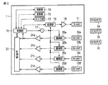
RFIDタグ位置検出装置1の内部には、図2に示したように、送信アンテナ11、4つの受信アンテナ12(12a,12b,12c,12d)、カメラ部13、照射部14、表示部15、制御部16、発振部17、変調部18、電力増幅部19、復調部20(20a,20b,20c,20d)、増幅部21(21a,21b,21c,21d)、および計測部22が配置されている。
As shown in FIG. 2, the RFID tag
制御部16は、図示しないCPU(Central Processing Unit)や記憶部を備えており、この記憶部に記憶されたプログラムに従って動作し、各部の制御を行う。すなわち制御部16は、カメラ部13、照射部14、表示部15、および計測部22の制御や、送信処理、受信処理およびパソコン等の上位機器との通信を行う。
The
発振部17は、高周波信号を発生し、これを変調部18や各復調部20a〜20dに出力する。発振部17の発振周波数は、RFIDタグ2へ送信する搬送波の周波数と同値である。この発信周波数は、制御部16からの信号に応じて変更することができる。
The
変調部18は、制御部16から出力された送信情報を発振部17の出力と合成して高周波信号を生成し、これを電力増幅部19に出力する。変調部18は、送信情報が無い場合には搬送波のみを出力することもある。
The
電力増幅部19は、変調部18から入力された高周波信号を増幅して送信アンテナ11に出力する。
The
送信アンテナ11は、電力増幅部19から出力された高周波信号を電波として空間に放射する。送信アンテナ11は、電波を特定の方向へ強く放射する特性を備えた指向性アンテナであり、例えば平面パッチアンテナを使用すればよい。
The
各受信アンテナ12a〜12dは、受信した電波を高周波信号に変換し、それぞれ復調部20a〜20dに出力する。各受信アンテナ12a〜12dは、位置検出の精度の観点からは、点であることが理想であるが、現実的には受信電波の波長に依存する大きさが必要である。なお、利得の高い指向性アンテナを使用する必要は無い。そのため、誘電率の高い材質を用いて波長短縮し、小型化したアンテナを使用することが好ましい。
Each of the
また、各受信アンテナ12a〜12dは、送信アンテナ11の放射利得の低い方向に配置することが好ましい。RFIDタグ2は、空間から届く搬送波を電力として使用し、バックスキャッタ変調をして応答を返す。そのため、RFIDタグ位置検出装置1は、搬送波を送信しながらバックスキャッタ信号を受信する動作を行うことになる。送信アンテナ11から空間を経て各受信アンテナ12a〜12dへ回り込む電波の電力を抑えることにより、受信回路における送信回り込みをキャンセルする処理の負担を軽減することができる。
Moreover, it is preferable to arrange | position each receiving
RFIDタグ2から放射された電波は、空間を通過して各受信アンテナ12a〜12dに到達する。このとき、RFIDタグ2と各受信アンテナ12a〜12dとの距離が異なるため、各受信アンテナ12a〜12dへの到達時間差が発生する。自由空間中を伝播する電波の速度は、約3×10⁸m/sある。例えば、RFIDタグ2および受信アンテナ12a間の距離と、RFIDタグ2および受信アンテナ12b間の距離との差が1mのときは、約3.3nsの到達時間差が生じ、同距離の差が10cmの場合は約330psの到達時間差が生じる。
The radio waves radiated from the
各受信アンテナ12a〜12dを同一平面上に配置する場合は、各受信アンテナ12a〜12dを頂点とする四角形としたときに、向かい合った角の和が180度にならないで、かつ、2つの対角線の中心が同じ点とならないように、各受信アンテナ12a〜12dを配置する。
When the receiving
各受信アンテナ12a〜12dを同一平面状に配置しない場合は、各受信アンテナ12a〜12dを頂点が正四面体の頂点とならないように配置する。
When the receiving
復調部20aは、受信アンテナ12aから出力される高周波信号と発振部17の出力を合成してベースバンド信号に変換し、これを増幅部21aに出力する。出力された信号は、一般的にはRSSI(Received Signal Strength Indication)と呼ばれる受信信号強度を測定するための振幅情報を含んでいる。各復調部20b〜20dも同様に、それぞれ受信アンテナ12b〜12dから出力される高周波信号と発振部17の出力を合成してベースバンド信号に変換し、これをそれぞれ増幅部21b〜21dに出力する。
The
増幅部21aは、復調部20aから出力される信号を増幅して飽和させ、“H(High)”または“L(Low)”で表される2値情報として出力する。RFIDタグ2が返すバックスキャッタ信号は2値情報であるため、このようにしてもRFIDタグ2が返す応答情報を再生することができる。各増幅部21b〜21dも同様に、それぞれ復調部20b〜20dから出力されるベースバンド信号を増幅して出力する。なお、各増幅部21a〜21dに代えてコンパレータを用いてもよい。
The amplifying
増幅部21aから出力された信号は、制御部16と計測部22に入力される。制御部16は、増幅部21aから出力された信号を受信データ(応答信号)に再生して、そのデータに応じた処理を行う。各増幅部21b〜21dから出力された信号も同様に、計測部22に入力されるが、制御部16には入力されない。なお、増幅部21aの出力のみ制御部16へ入力するとしたが、増幅部21b〜21dから出力された信号を制御部16に入力する構成としてもよい。
The signal output from the
各増幅部21a〜21dの出力が“L”から“H”に変化するタイミングは、RFIDタグ2からの電波が各受信アンテナ12a〜12dに到達した時間によって決まる。計測部22は、各増幅部21a〜21dから入力された信号の時間差を検出し、それぞれの時間差と受信アンテナ12a〜12dの座標とに基づいてバックスキャッタ信号を返したRFIDタグ2の座標を算出する。ここで算出される座標は、RFIDタグ位置検出装置1を基準とした相対的な座標である。計測部22は、算出した相対座標値を制御部16へ出力する。
The timing at which the outputs of the amplifying
[時間計測]
図3に計測部22の概略ブロック図を示している。計測部22は、4つのTDC(Time to Digital Converter)23(23a,23b,23c,23d)および演算部24を備えている。
[Time measurement]
FIG. 3 shows a schematic block diagram of the measuring
各TDC23a〜23dは、Start入力用の端子と、Stop入力用の端子と、出力端子とを有している。各TDC23a〜23dは、Start入力が“L”から“H”に変化した後に、Stop入力が“L”から“H”に変化するまでの時間に応じたデジタル値を出力する。近年は、180nmプロセスのCMOS(Complementary Metal Oxide semiconductor)技術を使用して、10ps程度の測定分解能が得られている。製造プロセスが微細化すれば、さらに短い時間を測定する分解能を得ることができる。 Each of the TDCs 23a to 23d has a Start input terminal, a Stop input terminal, and an output terminal. Each of the TDCs 23a to 23d outputs a digital value corresponding to the time until the Stop input changes from “L” to “H” after the Start input changes from “L” to “H”. In recent years, measurement resolution of about 10 ps has been obtained by using 180 nm process complementary metal oxide semiconductor (CMOS) technology. If the manufacturing process is miniaturized, resolution for measuring a shorter time can be obtained.
各TDC23a〜23dのStart入力用の端子は、制御部16と接続されている。TDC23aのStop入力用の端子は、増幅部21aと接続されている。TDC23b〜23dのStop入力用の端子も同様に、それぞれ増幅部21b〜21dと接続されている。各TDC23a〜23dの出力端子は、演算部24に接続されている。
The Start input terminals of the TDCs 23 a to 23 d are connected to the
各TDC23a〜23dの動作を図4に示す信号波形を参照して説明する。 The operation of each of the TDCs 23a to 23d will be described with reference to the signal waveforms shown in FIG.
先ず、各TDC23a〜23dへのStart入力およびStop入力は、全て“L”になっている。制御部16からのStart入力が“H”になると、各TDC23a〜23dがそれぞれ時間測定を開始する。TDC23aへのStop入力が“H”になると、TDC23aは、計測時間としてtaを出力する。次に、TDC23cへのStop入力が“H”になると、TDC23cは、計測時間としてtcを出力する。TDC23dへのStop入力が“H”になると、TDC23dは、計測時間としてtdを出力する。TDC23bへのStop入力が“H”になると、TDC23bは、計測時間としてtbを出力する。
First, the Start input and Stop input to each of the TDCs 23a to 23d are all "L". When the Start input from the
演算部24は、図示しない記憶部を備えており、この記憶部に記憶されたプログラムに従って動作し、入力された各計測時間ta,tb,tc,tdから、各信号の到達時間差を算出する。受信アンテナ12aと受信アンテナ12bの到達時間差tbaは、tb−taから求まり、受信アンテナ12aと受信アンテナ12cの到達時間差tcaは、tc−taから求まり、受信アンテナ12aと受信アンテナ12dの到達時間差tdaは、td−taから求まる。
The
このように各到達時間差tba,tca,tdaを求めた後、受信アンテナ12a〜12dの座標を用いて、バックスキャッタ応答を返したRFIDタグ2の座標を算出する。ここで算出する座標は、RFIDタグ位置検出装置1からの相対的な座標である。
After obtaining the arrival time differences t ba , t ca , and t da as described above, the coordinates of the
上記のように制御部16は、各TDC23a〜23dへのStart入力を“H”にすることで、計測部22に時間計測を開始させる。各TDC23a〜23dへのStart入力を“H”にするタイミングは、受信アンテナ12aから制御部16に入力される信号に応じて決定されるが、その決定方法については後述する。
As described above, the
[座標演算]
図5を用いてRFIDタグ2の座標演算について説明する。
受信アンテナ12aの座標は(xa,ya,za)、受信アンテナ12bの座標は(xb,yb,zb)、受信アンテナ12cの座標は(xc,yc,zc)、受信アンテナ12dの座標は(xd,yd,zd)で既知であり、演算部24が有する記憶部等に予め記憶されている。
[Coordinate calculation]
The coordinate calculation of the
The coordinates of the receiving
バックスキャッタ応答を返したRFIDタグ2の座標をP点(xP,yP,zP)とし、電波の伝達速度をCとすると、各受信アンテナ12a〜12dの座標と到達時間差tba,tca,tdaとを用いて下記式が成立する。

xP,yP,zP以外は既知の値であるため、上記3つの連立方程式を解くことにより、xP,yP,zPの値を求めることができる。この非線形連立方程式は、ニュートン法等の数値計算方法を使用することによって解を求めることができる。各受信アンテナ12a〜12dが同一平面に配置されている場合は、解が2つ存在する。送信アンテナ11がz=0となる面にあるなら、アンテナ利得の高い側にある解(正の解)を有効とすればよい。このようにすることにより、バックスキャッタ応答を返したRFIDタグ2の相対座標を取得することができる。
Since values other than x P , y P and z P are known values, the values of x P , y P and z P can be obtained by solving the above three simultaneous equations. The nonlinear simultaneous equations can be solved by using a numerical calculation method such as Newton's method. When the receiving
ここで、RFIDタグ位置検出装置1とRFIDタグ2との通信について、図6を用いて説明する。
本実施形態におけるRFIDタグ位置検出装置1とRFIDタグ2とは、近年広く普及しつつあるEPCglobalのClass1Generation2規格(以下、C1G2規格)に従って通信するものとする。
Here, communication between the RFID tag
The RFID tag
図6の上段は、RFIDタグ位置検出装置1の送信データであり、斜線を付した部分は搬送波のみが送信されている状態を示している。図6の下段は、RFIDタグ2の送信データである。C1G2規格の通信においては、先ずRFIDタグ位置検出装置1が搬送波を送信する。RFIDタグ2は、この搬送波を受信することによって起動する。
The upper part of FIG. 6 shows transmission data of the RFID tag
RFIDタグ位置検出装置1は、プリアンブル(P)に引き続き、読取り開始を知らせるQuery(Q)を送信する。RFIDタグ2は、プリアンブル(P)を受信すると、受信速度を決定して、引き続くデータを受信できるように同期を取り、Query(Q)を受信すると、そのQuery(Q)の内容に従った設定を行う。その後、C1G2規格では、RFIDタグ2はランダムに選択したスロットで応答を送信するが、本実施形態では、RFIDタグ2が直ちに応答を送信するとして説明する。
The RFID tag
RFIDタグ2は、Query(Q)を受信した後、プリアンブル(P)に引き続き、16ビットの擬似乱数であるRN16を送信する。RN16は、以後の通信の間、保持されており、暗号文字列として使用される。RFIDタグ位置検出装置1は、プリアンブル(P)とRN16とを受信すると、フレーム同期を取るためのFrame−Sync(F)に引き続き、正しく受信できたことを知らせるACKを送信する。RFIDタグ2は、ACKを受信すると、プリアンブル(P)とデータ(Data)とCRC(Cyclic Redundancy Check)を送信する。このデータ(Data)の中に、RFIDタグ2毎に固有の識別情報、すなわちC1G2規格のEPC(Electronic Product Code)が含まれている。CRCは、データ伝送の誤りを検出するために付加する符号である。
After receiving the Query (Q), the
RFIDタグ位置検出装置1は、プリアンブル(P)、データ(Data)、CRCを受信すると、そのCRCを用いて伝送エラーの有無を検出する。その結果、正しく受信したと判断したときは、Frame−sync(F)に引き続き、QueryRep(QR)を送信する。一方、正常に受信できなかったと判断した場合は、QueryRep(QR)に代えて、正常に受信できなかったことを通知するNAKを送信し、RFIDタグ2に再送を要求する。RFIDタグ位置検出装置1の交信領域内にあるRFIDタグ2が1つだけのときは、ここまでの処理で通信が完了する。
When receiving the preamble (P), data (Data), and CRC, the RFID tag
RFIDタグ位置検出装置1の交信領域内にRFIDタグ2が複数ある場合は、QueryRep(QR)の後に、別のRFIDタグ2がプリアンブル(P)とRN16とを送信する。RFIDタグ位置検出装置1は、RN16を受信すると、Frame−Sync(F)とACKとを送信し、これを受信したRFIDタグ2がプリアンブル(P)、データ(Data)およびCRCを送信する。RFIDタグ位置検出装置1は、データ(Data)を正常に受信すると、Frame−Sync(F)を送信する。
このような処理を繰り返すことによって、RFIDタグ位置検出装置1は、交信領域内にある複数のRFIDタグ2の識別情報を検出する。
When there are a plurality of
By repeating such processing, the RFID tag
図7にRFIDタグ2がRFIDタグ位置検出装置1へ送信するプリアンブルの波形を示している。なお、図7は、C1G2規格でFM0符合を使用するときのプリアンブルである。FM0符合においては、“0”を表すときは1ビットの中心でレベルを“H”から“L”または“L”から“H”に反転させ、“1”を表すときは1ビットの中でレベルを一定に保ち、変化させない。また、あるビットから次のビットに切り替わるときにレベルを反転させる。“V”は、FM0符合のルールに従わないビットであり、プリアンブルの中だけに表れるものである。
FIG. 7 shows a waveform of a preamble transmitted from the
通常、プリアンブルの先頭においては、ビット同期をとるために、同じパターンが繰り返される。その後、別の決められたパターンを使用して、プリアンブルの後に続く情報との境目がわかるようにしている。図7では、“0”が5つ連続で現れている箇所がビット同期に使用され、その後の“1010V1”より後がデータとなる。 Normally, the same pattern is repeated at the beginning of the preamble in order to achieve bit synchronization. After that, another predetermined pattern is used so that the boundary with the information following the preamble can be understood. In FIG. 7, a portion where five “0” s appear in succession is used for bit synchronization, and data after “1010V1” after that is data.
このように、RFIDタグ位置検出装置1は、ACKを送信した後に識別情報を含むデータを受信するとの手順で通信する。したがって制御部16は、ACK送信後のプリアンブルを受信し、ビット同期をとった後においては、受信信号のレベルが変化するタイミングを予想できる。制御部16は、ビット同期をとって“V”を検出した直後、受信信号レベルが“L”から“H”に最初に変化する前に各TDC23a〜23dのStart入力を一斉に“H”にすることで、各受信アンテナ12a〜12dの受信信号のレベルが次に“H”に変化するまでの時間ta,tb,tc,tdを測定することができる。
As described above, the RFID tag
なお、図2のブロック図では、増幅部21aの出力を制御部16に入力して、RFIDタグ2からの受信データの取得を行っている。RFIDタグ2から受信アンテナ12aまでの距離が最短ではなく、RFIDタグ2から他の受信アンテナ12b〜12dまでの距離の方が短いこともある。各受信アンテナ12a〜12dが図5のように配置されているとき、受信アンテナ12aから最も遠くにある受信アンテナが受信アンテナ12dであるとすると、受信アンテナ12aと受信アンテナ12dの最大到達時間差tmは、下記の式で表すことができる。
他の受信アンテナ12aの最も遠くにある受信アンテナが他のアンテナである場合でも、同様の計算式にて受信アンテナ12aとそのアンテナとの最大到達時間差tmを求めることができる。
Even when the farthest receiving antenna of the other receiving
これらを考慮し、“V”が検出された直後において受信信号のレベルが“L”から“H”に変化すると予想されるタイミングからtmより前の時間に、各TDC23a〜23dへのStart入力を“H”にすればよい。言い換えると、時間測定を開始するタイミングは、最大受信アンテナ間距離を電波が伝達する時間より後に各受信アンテナ12a〜12dの受信信号レベルが変化するように設定すればよい。
Considering these, the Start input to each of the TDCs 23a to 23d at a time before t m from the timing at which the level of the received signal is expected to change from “L” to “H” immediately after “V” is detected. Should be set to “H”. In other words, the timing for starting the time measurement may be set so that the received signal level of each of the receiving
また、測定時間が長すぎると、次の受信信号レベルの変化点が現れてしまうので、次の変化点が現れる前に測定を終了することが好ましい。伝送速度と符号化方式により、信号レベルの変化点が現れる時間間隔が決まるので、これから測定終了時間を決めればよい。このようにすることによって、各受信アンテナ12a〜12dとRFIDタグ2の配置に関係無く、全ての受信アンテナ12a〜12dに到達する信号のレベル変化タイミングを捉えることができる。そして、測定した時間差からRFIDタグ2の位置を特定することができる。
If the measurement time is too long, a change point of the next received signal level appears. Therefore, it is preferable to end the measurement before the next change point appears. The time interval at which the change point of the signal level appears is determined by the transmission rate and the encoding method, so the measurement end time can be determined from this. By doing in this way, the level change timing of the signal which reaches | attains all the receiving
このように、RFIDタグ位置検出装置1は、識別情報を含むデータのプリアンブルを利用してRFIDタグ2の位置を検出するため、RFIDタグ2の識別情報と位置を一度に検出することができる。複数のRFIDタグ2の識別情報を検出した場合は、それぞれの識別情報に対応する位置も検出することができる。
Thus, since the RFID tag
なお、本実施形態では“V”の位置で各TDC12a〜12dのStart入力を“H”にするが、ビット同期が取れた後であれば、任意の受信信号レベルの変化点付近で同様に時間を測定することができる。 In this embodiment, the Start input of each of the TDCs 12a to 12d is set to “H” at the position “V”. However, after bit synchronization is established, the time is similarly changed in the vicinity of the change point of an arbitrary received signal level. Can be measured.
[表示部への情報表示]
さて、RFIDタグ位置検出装置1は、RFIDタグ2の相対座標を算出し、その相対座標と、同座標の算出時にRFIDタグ2から受信した識別情報あるいはそれに基づいて特定される情報を関連付けて表示部15に表示する機能を有している(出力手段)。
図8は、RFIDタグ位置検出装置1の表示部15に表示される画像を説明するための模式図である。表示部15は、図示したようにRFIDタグ位置検出装置1の背面(カメラ部13のレンズ等が設けられた面と反対側の面)に設けられている。
[Displaying information on the display]
The RFID tag
FIG. 8 is a schematic diagram for explaining an image displayed on the
図中の30は、それぞれRFIDタグ2が取り付けられた物品であり、各RFIDタグ2はいずれもRFIDタグ位置検出装置1の交信領域内にあるものとする。表示部15には、カメラ部13で撮影された画像が表示され、各RFIDタグ2との通信によって検出した各RFIDタグ2の相対座標に対応する画像上には、各RFIDタグ2から検出した識別情報に基づく情報31が重ね合わせて(関連付けて)表示される。各情報31は、各RFIDタグ2から検出した識別情報そのままでもよいが、その識別情報に紐付けられた物品情報としてもよい。この場合、例えば制御部16の記憶部に識別情報と物品情報との対応を示すテーブルを予め記憶しておき、そのテーブルを参照して識別情報に紐付けられた物品情報を特定すればよい。このように情報31を物品情報とすれば、表示部15に映し出された物品の種別を認識し易くなる。
情報31の表示に関する各部の動作を、図9のフローチャートに沿って説明する。
上位機器からコマンドを受信するなどして処理開始が指示されると、カメラ部13により画像が撮影され、それが表示部15に表示される。その後、図9に示す処理が開始される。
The operation of each part relating to the display of the
When the start of processing is instructed by receiving a command from the host device or the like, an image is taken by the
開始当初においては、先ず前述した方法により交信領域内にあるRFIDタグ2の位置が検出される(ステップ:ST1〜ST11)。すなわち、送信アンテナ11からの搬送波の送信が開始されて(ST1)、交信領域内にあるRFIDタグ2が起動される。次に、送信アンテナ11からQuery(Q)が送信され(ST2)、これに対するRN16が受信アンテナ12aにより受信される(ST3)。その後、送信アンテナ11からACKが送信され(ST4)、応答を返したRFIDタグ2の識別情報を含むデータの受信が開始される(ST5)。そして、そのRFIDタグ2から送信されるプリアンブル(P)に含まれる“1010V”の受信中に、制御部16が前述したタイミングで各TDC23a〜23dのStart入力を“H”にする(ST6)。その結果、Start入力が“H”になってから各Stop入力が“H”になるまでの時間ta,tb,tc,tdが各TDC23a〜23dから演算部24に出力される(ST7)。演算部24は入力された計測時間ta,tb,tc,tdに基づいて受信アンテナ12a〜12d毎の到達時間差tba,tca,tdaを算出し(ST8)、それらに基づいて応答を返したRFIDタグ2の相対座標を算出する(ST9)。相対座標の算出が行われた後に応答を返したRFIDタグ2からの識別情報を含むデータの受信が完了し(ST10)、送信アンテナ11からQueryRep(QR)が送信される(ST11)。
Initially, the position of the
なお、ST8とST9における演算がST10におけるデータの受信完了前に行われるとしたが、ST8とST9における演算がST10におけるデータの受信完了後に行われてもよい。 Although the calculations in ST8 and ST9 are performed before the completion of data reception in ST10, the calculations in ST8 and ST9 may be performed after the completion of data reception in ST10.
ST11の後、制御部16により、ST9で算出された相対座標が画面への表示座標に変換され、変換後の座標にRFIDタグ2から受信した識別情報に基づく情報が表示される(ST12)。その後、図示したフローチャートに沿う処理を開始してからQueryRep(QR)を所定回数送信したかを判断し、所定回数送信していない場合は(ST13の“N”)、交信領域内にある他のRFIDタグ2を対象としてST3〜ST12の処理が行われる。一方、QueryRep(QR)を所定回数送信し終えた場合は(ST13の“Y”)、一連の処理が終了する。
After ST11, the
ST12にて行う座標変換を説明するための図を図10に示している。x−z面を上段に、y−z面を下段右に、表示部15への画面表示座標を下段左に示す。相対座標を検出したRFIDタグ2の座標をP点(xP,yP,zP)とし、カメラ部13の撮像点の座標をe点(xe,ye,ze)とし、ze=0としている。カメラ部13の画像の取得範囲は、x−z面では±θの範囲であり、y−z面では±φの範囲である。
FIG. 10 is a diagram for explaining the coordinate conversion performed in ST12. The xz plane is shown at the top, the yz plane is shown at the bottom right, and the screen display coordinates on the
カメラ部13によって撮像される画像はx−y面で表されるため、RFIDタグ2の位置を表示するためには、三次元座標を画像座標に変換する必要がある。
Since the image picked up by the
カメラ部13の撮像点からRFIDタグ2までのz軸上の距離はzPである。カメラ部13で撮像される画像の距離zPにおけるx軸の範囲は、−zP/cosθ〜zP/cosθとなる。xw=zP/cosθとすると、−xw≦(距離zPにおけるx軸の取得範囲)≦xwとなる。カメラ部13の撮像画像におけるRFIDタグ2のx座標は、xP−xeとして表される。
Distance on the z-axis from the imaging point of the
カメラ部13で取得する距離zPにおけるy軸の範囲は、−zP/sinφ〜zP/sinφとなる。yw=zP/sinφとすると、−yw≦(距離zPにおけるy軸の取得範囲)≦ywとなる。カメラ部13の撮像画像におけるRFIDタグ2のy座標は、yP−yeとして表される。
The y-axis range of the distance z P acquired in the camera unit 13, the -z P / sinφ~z P / sinφ. When y w = z P / sinφ, −y w ≦ (y-axis acquisition range at distance z P ) ≦ y w . The y coordinate of the
表示部15に画像を表示するときは、(xw,yw)を表示画像の右上隅とし、(−xw,yw)を表示画像の左上隅とし、(xw,−yw)を表示画像の右下隅とし、(−xw,−yw)を表示画像の左下隅として、上記のように算出したRFIDタグ2の表示座標(xP−xe,yP−ye)に相当する位置に、当該RFIDタグ2に対応する情報31を表示する。
When an image is displayed on the display section 15, (x w, y w) and the upper right corner of the display image, (- x w, y w ) and the upper left corner of the display image, (x w, -y w) Is the lower right corner of the display image and (−x w , −y w ) is the lower left corner of the display image, and the display coordinates (x P −x e , y P −y e ) of the
このようにすることで、複数のRFIDタグ2の識別情報と相対位置を取得し、取得した複数のRFIDタグ2の場所を人に分かり易く報知することができ、入出荷の物品管理や棚卸を効率良く行うことができる。
In this way, the identification information and relative positions of the plurality of
また、表示画像中のRFIDタグ2があるはずの場所に、識別情報等の情報31が表示されないときは、その場所にあるはずのRFIDタグ2が読み取れなかったと判断できる。そして、直ちに読み取れなかったRFIDタグ2の位置を知ることができる。
Further, when the
[タグ位置へのレーザ照射]
RFIDタグ位置検出装置1は、RFIDタグ2の位置を検出し、その位置を照射部14からのレーザ照射で示す機能を有している。
図11は、照射部14によりレーザ光(光線)が照射される様子を示す模式図である。この機能は、既に各RFIDタグ2の識別情報が判明しており、複数のRFIDタグ2の中から特定のRFIDタグ2を探し出すときなどに使用する。すなわち、RFIDタグ位置検出装置1が、特定の識別情報を記憶しているRFIDタグ2dのみが応答するコマンドを送信し、応答したRFIDタグ2dの相対座標を取得し、取得した相対座標に向けて照射部14からレーザ光42を照射して、RFIDタグ2dの位置を知らせる。
[Laser irradiation to tag position]
The RFID tag
FIG. 11 is a schematic diagram illustrating a state in which laser light (light beam) is irradiated by the
レーザ光の照射に関する各部の動作を、図12のフローチャートに沿って説明する。
上位機器からコマンドを受信するなどして処理開始が指示されると、そのコマンドで示されるRFIDタグ2を処理対象として図12に示す処理が開始される。
The operation of each unit related to the laser light irradiation will be described with reference to the flowchart of FIG.
When a process start is instructed by receiving a command from the host device or the like, the process shown in FIG. 12 is started with the
開始当初においては、先ず処理対象であるRFIDタグ2の位置が検出される(ステップ:ST21〜ST32)。すなわち、送信アンテナ11からの搬送波の送信が開始されて(ST21)、交信領域内にあるRFIDタグ2が起動される。次に、送信アンテナ11から処理対象であるRFIDタグ2を指定したSelectコマンドが送信される(ST22)。このSelectコマンドを受信したRFIDタグ2は、同コマンドにて自身が指定されている場合に限り、以降のQuery(Q)等に応答する。
At the beginning of the start, first, the position of the
続いて、送信アンテナ11からQuery(Q)が送信され(ST23)、これに対して処理対象のRFIDタグ2が返すRN16が、受信アンテナ12aにより受信される(ST24)。その後、送信アンテナ11からACKが送信され(ST25)、処理対象のRFIDタグ2の識別情報を含むデータの受信が開始される(ST26)。そして、そのRFIDタグ2から送信されるプリアンブル(P)に含まれる“1010V”の受信中に、制御部16が前述したタイミングで各TDC23a〜23dのStart入力を“H”にする(ST27)。その結果、Start入力が“H”になってから各Stop入力が“H”になるまでの時間ta,tb,tc,tdが各TDC23a〜23dから演算部24に出力される(ST28)。演算部24は、入力された計測時間ta,tb,tc,tdに基づいて受信アンテナ12a〜12d毎の到達時間差tba,tca,tdaを算出し(ST29)、それらに基づいて処理対象のRFIDタグ2の相対座標を算出する(ST30)。相対座標の算出が行われた後に処理対象のRFIDタグ2からの識別情報を含むデータの受信が完了し(ST31)、送信アンテナ11からQueryRep(QR)が送信される(ST32)。
Subsequently, Query (Q) is transmitted from the transmission antenna 11 (ST23), and the
なお、ST29とST30における演算がST31におけるデータの受信完了前に行われるとしたが、ST29とST30における演算がST31におけるデータの受信完了後に行われてもよい。 Although the calculations in ST29 and ST30 are performed before the completion of data reception in ST31, the calculations in ST29 and ST30 may be performed after the completion of data reception in ST31.
ST32の後、制御部16により、ST9で算出された相対座標がレーザ光の照射座標に変換され、変換後の座標に照射部14からレーザ光が照射される(ST33)。以上で一連の処理が終了する。
After ST32, the
ここで、照射部14の構造および照射座標の算出方法について説明する。
図13は、照射部14の概略構造を示す模式図である。照射部14は、レーザ光を出力する光源40と、レーザ光の照射角度を調整するミラー41とを備えている。光源40は、ミラー41に向かってレーザ光を出力し、ミラー41でレーザ光の進行方向を変える。図示した矢印42は、RFIDタグ位置検出装置1から照射されるレーザ光の進行方向を示している。ミラー41は、x軸方向の回転軸43とy軸方向の回転軸44で回転可能となるように支持されている。各回転軸43,44における回転角度を調整してミラー41の向きを変えることにより、ミラー41で反射されるレーザ光を所望の方向に向けることができる。
Here, the structure of the
FIG. 13 is a schematic diagram illustrating a schematic structure of the
ST33にて行う座標変換とミラー41の角度との関係を説明するための図を、図14に示している。x−z面を上段に、y−z面を下段右に、x,y,z軸からなる三次元座標系を下段左に示す。相対座標を取得した処理対象のRFIDタグ2の座標をP点(xP,yP,zP)とし、レーザ光を向ける座標をf点(xf,yf,zf)とし、zf=0としている。
FIG. 14 is a diagram for explaining the relationship between the coordinate transformation performed in ST33 and the angle of the mirror 41. In FIG. The xz plane is on the top, the yz plane is on the bottom right, and the three-dimensional coordinate system consisting of the x, y, and z axes is shown on the bottom left. The coordinates of the
ミラー41の角度を調整する前の初期照射方向は、f点からx−y面に垂直なz方向であるとする。そうすると、x−z面においてはf点からθ1=arctan{zP/(xP−xf)}方向にP点が所在し、y−z面ではf点からφ1=arctan{zP/(yP−xf)}方向にP点が所在することになる。したがって、ミラー41をy軸方向の回転軸43を軸としてθ1回転させ、x軸方向の回転軸44を軸としてφ1回転させることにより、処理対象のRFIDタグ2の座標P点に向けてレーザ光を照射することができる。
It is assumed that the initial irradiation direction before adjusting the angle of the mirror 41 is the z direction perpendicular to the xy plane from the point f. Then, in the xz plane, the P point is located in the direction θ 1 = arctan {z P / (x P −x f )} from the f point, and in the yz plane, φ 1 = arctan {z P The point P is located in the / (y P −x f )} direction. Therefore, the mirror 41 is rotated by θ 1 about the
このように特定のRFIDタグ2に向けてレーザ光が照射されれば、探しているRFIDタグ2の場所を容易に知ることができる。なお、算出した相対座標には計測や演算による誤差が含まれるため、RFIDタグ2の実際の座標と算出した座標とが若干異なることがある。そのため、レーザ光を拡散させて、照射範囲を広げるようにしてもよい。
If the laser beam is irradiated toward the
[タグ不在の報知]
RFIDタグ位置検出装置1は、予め定められた設定範囲外にそれまで同範囲内に在ったRFIDタグ2が出たことに応じて、その旨を報知する機能(報知手段)を有している。
図15は、当該機能を説明するための模式図である。送信アンテナ11および受信アンテナ12a〜12dによる交信領域51の内部に、設定範囲52を定める。設定範囲52の相対座標は、制御部16の記憶部等に予め記憶しておく。先ず、設定範囲52の内側にRFIDタグ2eがあり、その後、RFIDタグ2eが設定範囲52の外側に移動したとする。当該機能において、RFIDタグ位置検出装置1は、RFIDタグ2eが設定範囲52内から設定範囲52外に出たか否かを検出し、設定範囲52外に出たことを検出したときに、その旨を報知する。
[Notification of absence of tag]
The RFID tag
FIG. 15 is a schematic diagram for explaining the function. A setting range 52 is defined inside the
当該機能に関する各部の動作を、図16のフローチャートに沿って説明する。
上位機器からコマンドを受信するなどして処理開始が指示されると、図16に示す処理が開始される。
The operation of each part related to the function will be described with reference to the flowchart of FIG.
When a command to start processing is received, for example, by receiving a command from the host device, the processing shown in FIG. 16 is started.
開始当初においては、先ず前述した方法により交信領域51内に在るRFIDタグ2の位置が検出される(ステップ:ST41〜ST51)。すなわち、送信アンテナ11からの搬送波の送信が開始されて(ST41)、交信領域内に在るRFIDタグ2が起動される。次に、送信アンテナ11からQuery(Q)が送信され(ST42)、これに対するRN16が受信アンテナ12aにより受信される(ST43)。その後、送信アンテナ11からACKが送信され(ST44)、応答を返したRFIDタグ2の識別情報を含むデータの受信が開始される(ST45)。そして、そのRFIDタグ2から送信されるプリアンブル(P)に含まれる“1010V”の受信中に、制御部16が前述したタイミングで各TDC23a〜23dのStart入力を“H”にする(ST46)。その結果、Start入力が“H”になってから各Stop入力が“H”になるまでの時間ta,tb,tc,tdが各TDC23a〜23dから演算部24に出力される(ST47)。演算部24は入力された計測時間ta,tb,tc,tdに基づいて受信アンテナ12a〜12d毎の到達時間差tba,tca,tdaを算出し(ST48)、それらに基づいて応答を返したRFIDタグ2の相対座標を算出する(ST49)。相対座標の算出が行われた後に応答を返したRFIDタグ2からの識別情報を含むデータの受信が完了し(ST50)、送信アンテナ11からQueryRep(QR)が送信される(ST51)。
At the beginning of the start, first, the position of the
なお、ST48とST49における演算がST50におけるデータの受信完了前に行われるとしたが、ST48とST49における演算がST50におけるデータの受信完了後に行われてもよい。 Although the calculations in ST48 and ST49 are performed before the completion of data reception in ST50, the calculations in ST48 and ST49 may be performed after the completion of data reception in ST50.
ST51の後、制御部16により、ST49で算出された相対座標と上記記憶部に記憶された設定範囲52の座標とに基づいて、当該RFIDタグ2が設定範囲52内に在るか否かが判定される(ST52)。その結果、設定範囲52内に在ると判定されたならば(ST52の「Y」)、交信領域51内にある他のRFIDタグ2を対象としてST42〜ST52の処理が行われる。一方、設定範囲52内に無いと判定されたならば(ST52の「N」)、そのRFIDタグ2が設定範囲52外に出たことが報知されて(ST53)、一連の処理が終了する。
After ST51, whether or not the
ST53における報知は、表示部15にメッセージ等を表示することで行ってもよいし、RFIDタグ位置検出装置1にスピーカ等をつなげて音声を出力することで行ってもよい。このような報知により、RFIDタグ2が決められたエリアの外に出されたことを知らせることができる。
The notification in ST53 may be performed by displaying a message or the like on the
なお、RFIDタグ2が設定範囲52内から設定範囲52外に出たときの説明をしたが、設定範囲52外から設定範囲52内に移動してきたことを検出したときに、その旨を報知するようにしてもよい。
The
以上説明したように、本実施形態におけるRFIDタグ位置検出装置1は、RFIDタグ2からの応答電波が4つの受信アンテナ12a〜12dに到達する時間差を用いてRFIDタグ2の位置を検出する。このような構成であれば、RFIDタグ2の位置検出に際し、RFIDタグ位置検出装置1を複数の位置に移動させる必要がない。したがって、RFIDタグ2の位置を迅速に検出できる。さらに、RFIDタグ位置検出装置1にRFIDタグ2との通信を複数回行わせる必要がないので、電波使用効率が悪くなることもない。
As described above, the RFID tag
また、RFIDタグ位置検出装置1は、位置を検出したRFIDタグ2に関する情報を、表示部15の表示画像上の対応する位置に重ね合わせて表示する機能や、検出された位置に向けてレーザ光を照射する機能を有する。このような機能を用いれば、特定のRFIDタグ2の所在を極めて容易に確認できる。
Further, the RFID tag
また、RFIDタグ位置検出装置1は、所定範囲に在るRFIDタグ2が同範囲から出たことを検出し、報知する機能を有する。このような機能を用いれば、所定範囲内におけるRFIDタグ2の入出を極めて容易に管理できる。
The RFID tag
(第2の実施形態)
次に、第2の実施形態について説明する。
第1の実施形態と同一の構成要素には同一の符号を付し、重複説明は必要な場合にのみ行う。
(Second Embodiment)
Next, a second embodiment will be described.
The same components as those in the first embodiment are denoted by the same reference numerals, and redundant description will be given only when necessary.
各受信アンテナ12a〜12dから計測部22までの間の回路で、回路遅延のばらつきや配線長のばらつき等が生じることがある。例えば、受信信号が、受信アンテナ12aから入力されてTDC23aに入力される時間と、受信アンテナ12bから入力されてTDC23bに入力される時間には、若干の差が生じ得る。この若干の差を補正すると、演算した相対座標と実際の座標のずれを小さくすることができる。
In a circuit between each of the receiving
そこで、本実施形態においては、上記ずれを最小減に止めるべく、到達時間差tba,tca,tdaの補正値を取得する機能(取得手段)を演算部24に設け、取得した補正値にて補正した後の到達時間差tba,tca,tdaを用いてRFIDタグ2の相対座標を演算する。
Therefore, in the present embodiment, a function (acquisition means) for acquiring correction values of the arrival time differences t ba , t ca , t da is provided in the
各受信アンテナ12a〜12dの間で生じる到達時間差のずれを補正する一例について説明する。
補正値の取得は、例えば補正モードなるモードでRFIDタグ位置検出装置1を起動した際に実行される。その際、予め受信アンテナ12aと受信アンテナ12bから等距離となる場所にRFIDタグ2を配置しておく。この状態で、第1の実施形態にて説明した方法にて相対座標の取得を行う。
An example of correcting a difference in arrival time difference that occurs between the receiving
The acquisition of the correction value is executed when the RFID tag
このとき、受信アンテナ12aと受信アンテナ12bへの電波の到達時間は同じであるため、回路における伝達遅延差がTDC23aとTDC23bの入力時間差Δtbaとして現れる。この時間差Δtbaは、補正値として例えば演算部24の記憶部に記憶される。回路における伝達遅延差が無い場合は、Δtba=0である。さらに、受信アンテナ12aと受信アンテナ12c、受信アンテナ12aと受信アンテナ12dとの間でも同様に補正値である時間差Δtca,Δtdaを取得する。
At this time, the reception for the
補正値を取得した後、通常の動作モードにおいてRFIDタグ2の相対座標を算出する際には、演算部24で取得した到達時間差tba,tca,tdaからそれぞれ上記時間差Δtba,Δtca,Δtdaが差し引かれて補正され、補正後の値を用いてRFIDタグ2の相対座標が演算される。
After acquiring the correction value, when calculating the relative coordinates of the
次に、到達時間差のずれを補正する他の例について説明する。
この例では、先ずRFIDタグ2を予めその相対座標が判明している位置に配置しておく。そうすると、このRFIDタグ2と各受信アンテナ12a〜12dとの距離が決まる。このとき、このRFIDタグ2と各受信アンテナ12a〜12dまでの距離と電波の伝達速度から、各受信アンテナ12a〜12d間の理論的な受信到達時間差を算出することができる。この時間差は、算出後の値をRFIDタグ位置検出装置1に外部から入力するようにしてもよいし、制御部16にて算出してもよい。
Next, another example of correcting the difference in arrival time difference will be described.
In this example, the
次に、補正モードにおいて上記RFIDタグ2の相対座標の取得を行い、そのときの受信到達時間差と理論的な受信到達時間差とを比較して、それぞれの差分を算出する。算出した差分は、例えば演算部24の記憶部に補正値として記憶する。
Next, the relative coordinates of the
以後、通常の動作モードにおいてRFIDタグ2の相対座標を演算する際には、上記記憶部に記憶したそれぞれの補正値を用いて、最初の例と同様に到達時間差tba,tca,tdaを補正する。
Thereafter, when calculating the relative coordinates of the
以上説明したように、本実施形態においては、算出した到達時間差tba,tca,tdaを補正する機能を設け、補正後の到達時間差を用いてRFIDタグ2の相対位置を検出するようにした。このようにしたことにより、回路遅延のばらつきや配線長のばらつきによる誤差が吸収され、RFIDタグ2の位置検出の精度が大幅に向上する。
As described above, in the present embodiment, a function for correcting the calculated arrival time differences t ba , t ca , and t da is provided, and the relative position of the
なお、第1の実施形態と同様の効果を奏することは言うまでもない。 Needless to say, the same effects as those of the first embodiment can be obtained.
(第3の実施形態)
次に、第3の実施形態について説明する。
第1,第2の実施形態と同一の構成要素には同一の符号を付し、重複説明は必要な場合にのみ行う。
(Third embodiment)
Next, a third embodiment will be described.
The same components as those in the first and second embodiments are denoted by the same reference numerals, and redundant description will be given only when necessary.
本実施形態においては、RFIDタグ2の絶対座標を算出する機能を、第1,第2の実施形態におけるRFIDタグ位置検出装置1の演算部24に設ける。
絶対座標を算出するために、予め当該RFIDタグ位置検出装置1を使用する建物内の柱等の固定された物体にRFIDタグ2を取り付けておき、このRFIDタグ2の絶対座標(xh,yh,zh)を取得して、演算部24の記憶部等に予め記憶しておく。但し、当該固定的な物体に取り付けられたRFIDタグ2に絶対座標を記憶させておき、これを任意のタイミングでRFIDタグ位置検出装置1により読み取ることにより、同RFIDタグ2の絶対座標を取得してもよい。
In the present embodiment, a function for calculating the absolute coordinates of the
In order to calculate the absolute coordinates, the
RFIDタグ位置検出装置1は移動せずに、絶対座標の知られているRFIDタグ2と絶対座標の知られていないRFIDタグ2との通信を行い、それぞれの相対座標を取得する。取得した絶対座標の知られているRFIDタグ2の相対座標は(xg,yg,zg)であり、絶対座標の知られていないRFIDタグ2の相対座標は(xP,yP,zP)であるとする。
The RFID tag
ここまでに取得した座標から、演算部24は、絶対座標の知られていないRFIDタグ2の絶対座標を(xh+xP−xg,yh+yP−yg,zh+zP−zg)と算出することができる。
From the acquired coordinates so far, the
このように算出した絶対座標は、例えば表示部15への表示やスピーカからの音声出力によって報知する。このようにすることにより、RFIDタグ位置検出装置1を基準としたRFIDタグ2の相対座標だけでなく、建物等を基準としたRFIDタグ2の絶対座標をも知ることができる。
The absolute coordinates calculated in this way are notified by, for example, display on the
なお、第1,第2の実施形態と同様の効果を奏することは言うまでもない。 Needless to say, the same effects as those of the first and second embodiments can be obtained.
(第4の実施形態)
次に、第4の実施形態について説明する。
第1〜第3の実施形態と同一の構成要素には同一の符号を付し、重複説明は必要な場合にのみ行う。
(Fourth embodiment)
Next, a fourth embodiment will be described.
The same components as those in the first to third embodiments are denoted by the same reference numerals, and redundant description will be given only when necessary.
本実施形態は、前記各実施形態における計測部の構成が異なるだけで、それ以外の構成は同じである。そのため、計測部についてのみ詳述する。 This embodiment is the same except for the configuration of the measurement unit in each of the above embodiments. Therefore, only the measurement unit will be described in detail.
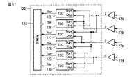
図17に本実施形態における計測部の概略ブロック図を示している。このブロック図は、図3で示した計測部22を計測部122に置き換えたものであり、TDCのStart入力に制御部16からの信号を使用しない構成を実現するものである。
FIG. 17 shows a schematic block diagram of the measurement unit in the present embodiment. This block diagram is obtained by replacing the
計測部122は、TDC125〜130と演算部124とで構成されている。TDC125は、増幅部21aの出力をStart入力とし、増幅部21bの出力をStop入力とし、Start入力が“H”になってからStop入力が“H”になるまでの時間tba+を演算部124に出力する。TDC126は、増幅部21bの出力をStart入力とし、増幅部21aの出力をStop入力とし、Start入力が“H”になってからStop入力が“H”になるまでの時間tba−を演算部124に出力する。
The
TDC127は、増幅部21aの出力をStart入力とし、増幅部21cの出力をStop入力とし、Start入力が“H”になってからStop入力が“H”になるまでの時間tca+を演算部124に出力する。TDC128は、増幅部21cの出力をStart入力とし、増幅部21aの出力をStop入力とし、Start入力が“H”になってからStop入力が“H”になるまでの時間tca−を演算部124に出力する。
The
TDC129は、増幅部21aの出力をStart入力とし、増幅部21dの出力をStop入力とし、Start入力が“H”になってからStop入力が“H”になるまでの時間tda+を演算部124に出力する。TDC130は、増幅部21dの出力をStart入力とし、増幅部21aの出力をStop入力とし、Start入力が“H”になってからStop入力が“H”になるまでの時間tda−を演算部124に出力する。
The
RFIDタグ2とRFIDタグ位置検出装置1の配置によって、増幅部21aと増幅部21bの出力が“H”になる順番が異なる。増幅部21aの出力が先に“H”になった場合、TDC125で受信アンテナ12a,12bの到達時間差が計測されることになり、TDC126では増幅部21bの出力が“H”になった後、次に増幅部21aの出力が“H”になるまでの時間が計測されるので、時間tba−は時間tba+よりも長くなる。逆に増幅部21bの出力が先に“H”になった場合、TDC126で受信アンテナ12a,12bの到達時間差が計測されることになり、TDC125では増幅部21aの出力が“H”になった後、次に増幅部21bの出力が“H”になるまでの時間が計測されるので、時間tba+は時間tba−よりも長くなる。これに鑑み、演算部124は、入力された時間tba+,tba−のうち、短い一方を演算に使用する時間として採用する。
The order in which the outputs of the amplifying
同様に、時間tca+,tca−の短い一方を演算に使用する時間として採用し、時間tda+,tda−の短い一方を演算に使用する時間として採用する。 Similarly, the shorter one of the times t ca + and t ca− is adopted as the time used for the calculation, and the shorter one of the times t da + and t da− is adopted as the time used for the calculation.
計測部の動作を説明すべく、各TDC125〜130の入出力波形の一例を図18に示す。図中のa〜dは、それぞれ増幅部21a〜21dの出力信号である。増幅部21aの出力が“H”になると、TDC125とTDC127とTDC129のStart入力が“H”になり、時間の計測を開始する。
In order to explain the operation of the measurement unit, an example of input / output waveforms of the
その後、増幅部21cの出力が“H”になると、TDC127のStop入力が“H”になり、TDC128のStart入力が“H”になる。TDC127は、Stop入力が“H”になったので、時間tca+を出力する。
Thereafter, when the output of the amplifying
次に、増幅部21dの出力が“H”になると、TDC129のStop入力が“H”になり、TDC130のStart入力が“H”になる。TDC129は、Stop入力が“H”になったので、時間tda+を出力する。
Next, when the output of the amplifying
次に、増幅部21bの出力が“H”になると、TDC125のStop入力が“H”になり、TDC126のStart入力が“H”になる。TDC125は、Stop入力が“H”になったので、時間tba+を出力する。
Next, when the output of the amplifying
図18の例では、TDC126とTDC128とTDC130は、時間測定が終了していない。時間測定可能な最大時間内に終了しない場合は、TDC126,128,130による測定終了時までの時間(上記最大時間)をそれぞれtba−,tca−,tda−とする。
In the example of FIG. 18, the
演算部124は、上記した通り、tba+とtba−、tca+とtca−、tda+とtda−を比較し、短い一方を座標演算用に採用する。採用した3つの時間は、各受信アンテナ12a〜12dへのRFIDタグ2からの応答の到達時間差である。演算部124は、これら到達時間差を用いて、応答したRFIDタグ2の相対座標を演算する。このような構成は、第1〜第3の実施形態いずれにも適用可能である。
As described above, the
なお、第1〜第3の実施形態と同様の効果を奏することは言うまでもない。 Needless to say, the same effects as those of the first to third embodiments can be obtained.
(変形例)
上記各実施形態にて開示した構成は、種々変形実施可能である。具体的な変形例としては、例えば次のようなものがある。
(Modification)
Various modifications can be made to the configurations disclosed in the above embodiments. Specific examples of modifications are as follows.
(1)上記各実施形態においては、受信アンテナ、復調部、および増幅部を4つずつ使用する場合を例示した。しかしながら、受信アンテナ、復調部、および増幅部の数は、5つ以上であってもよい。
受信アンテナ等が5つ以上ある場合は、例えばニュートン法に最小二乗法を組み合わせた演算方法を使用することにより、RFIDタグ2の相対座標を求めることができる。受信到達時間差を計測する数が多くなると、算出した相対座標が実際の座標に近づく傾向があるので、受信アンテナ、復調部、および増幅部を5つ以上使用することで、RFIDタグ位置検出装置の位置検出性能を高めることができる。
(1) In each of the above embodiments, the case where four reception antennas, four demodulation units, and four amplification units are used has been exemplified. However, the number of reception antennas, demodulation units, and amplification units may be five or more.
When there are five or more receiving antennas or the like, the relative coordinates of the
(2)上記各実施形態では、制御部16や演算部24,124の記憶部に各処理用のプログラムが予め記憶されているものとして説明した。しかしながら、これに限らず各プログラムをネットワークからRFIDタグ位置検出装置にダウンロードしても良いし、同様の機能を記録媒体に記憶させたものをRFIDタグ位置検出装置にインストールしてもよい。記録媒体としては、CD−ROM等を利用でき、かつRFIDタグ位置検出装置が読み取り可能な記録媒体であれば、その形態は何れの形態であってもよい。またこのように予めインストールやダウンロードにより得る機能はRFIDタグ位置検出装置内部のOS(Operating System)等と協働してその機能を実現させるものであってもよい。
(2) In each of the above embodiments, the processing program has been described as being stored in advance in the storage unit of the
本発明のいくつかの実施形態を説明したが、これらの実施形態は、例として提示したものであり、発明の範囲を限定することは意図していない。これら新規な実施形態は、その他の様々な形態で実施されることが可能であり、発明の要旨を逸脱しない範囲で、種々の省略、置き換え、変更を行うことができる。これら実施形態やその変形は、発明の範囲や要旨に含まれるとともに、特許請求の範囲に記載された発明とその均等の範囲に含まれる。 Although several embodiments of the present invention have been described, these embodiments are presented by way of example and are not intended to limit the scope of the invention. These novel embodiments can be implemented in various other forms, and various omissions, replacements, and changes can be made without departing from the scope of the invention. These embodiments and modifications thereof are included in the scope and gist of the invention, and are included in the invention described in the claims and the equivalents thereof.
1…RFIDタグ位置検出装置、2…RFIDタグ、11…送信アンテナ、12…受信アンテナ、13…カメラ部、14…照射部、15…表示部、16…制御部、17…発振部、18…変調部、19…電力増幅部、20…復調部、21…増幅部、22…計測部、23…TDC、24…演算部
DESCRIPTION OF
Claims (12)
同一平面上に配置され、前記RFIDタグからの応答信号を受信する4つの受信アンテナと、
前記各受信アンテナが受信した応答信号に応じて出力する信号の時間差を計測し、計測した各時間差に基づいて前記RFIDタグの相対座標を演算する計測部と、
を備え、
前記4つの受信アンテナを頂点とする四角形としたとき、向かい合った角の和が180度にならないで、かつ、2つの対角線の中心が同じ点とならないように配置したことを特徴とするRFIDタグ位置検出装置。 A transmitting antenna for transmitting signals to the RFID tag;
Four receiving antennas arranged on the same plane and receiving a response signal from the RFID tag;
Measuring a time difference between signals output according to response signals received by the receiving antennas, and calculating a relative coordinate of the RFID tag based on the measured time differences;
Equipped with a,
An RFID tag characterized in that when the four receiving antennas have a quadrangular shape, the sum of opposite angles does not become 180 degrees and the centers of two diagonal lines do not become the same point. Position detection device.
前記計測部は、時間計測開始の後、前記各受信アンテナから入力される信号が変化するまでの時間をそれぞれ計測し、計測した各時間を用いて前記各時間差を算出することを特徴とする請求項2に記載のRFIDタグ位置検出装置。 The control unit causes the measurement unit to start measuring time at a predetermined timing determined according to a signal input from the reception antenna,
The measurement unit measures a time until a signal input from each receiving antenna changes after starting the time measurement, and calculates each time difference using each measured time. Item 3. The RFID tag position detection device according to Item 2.
前記各時間差から演算された相対座標と、その演算に用いられた各時間差の計測時に受信された識別情報又はその識別情報に基づいて特定される情報とを関連付けて出力する出力手段をさらに備えていることを特徴とする請求項1乃至5のうちいずれか1に記載のRFIDタグ位置検出装置。 Measurement of each time difference by the measurement unit is performed at the time of receiving a response signal including identification information unique to the RFID tag,
It further comprises an output means for associating and outputting the relative coordinates calculated from each time difference and the identification information received at the time of measuring each time difference used for the calculation or information specified based on the identification information. The RFID tag position detecting device according to any one of claims 1 to 5, wherein
画像を撮影するカメラ部と、
を備え、
前記出力手段は、前記カメラ部で撮影した画像を前記表示部に表示させると共に、その表示画像上における前記計測部が演算した相対座標に相当する位置に、その演算に用いられた各時間差の計測時に受信された識別情報又はその識別情報に基づいて特定される情報を表示することを特微とする請求項6に記載のRFIDタグ位置検出装置。 A display unit;
A camera unit for taking images,
With
The output means displays an image captured by the camera unit on the display unit, and measures each time difference used for the calculation at a position corresponding to the relative coordinates calculated by the measurement unit on the display image. 7. The RFID tag position detection device according to claim 6, wherein the identification information sometimes received or information specified based on the identification information is displayed.
当該指定したRFIDタグの前記計測部によって演算された相対座標に相当する方向に向けて光線を出力する照射部をさらに備えていることを特徴とする請求項1乃至5のうちいずれか1に記載のRFIDタグ位置検出装置。 The transmitting antenna transmits a signal to which one designated RFID tag responds,
6. The irradiation unit according to claim 1, further comprising an irradiation unit that outputs a light beam in a direction corresponding to a relative coordinate calculated by the measurement unit of the designated RFID tag. RFID tag position detection device.
前記計測部は、計測した各時間差を前記取得手段によって取得された補正値にて補正し、補正後の各時間差を用いてRFIDタグの相対座標を演算することを特徴とする請求項1乃至9のうちいずれか1に記載のRFIDタグ位置検出装置。 An acquisition means for acquiring a correction value for each time difference measured by the measurement unit;
The said measurement part correct | amends each measured time difference with the correction value acquired by the said acquisition means, and calculates the relative coordinate of a RFID tag using each corrected time difference. The RFID tag position detection device according to any one of the above.
前記RFIDタグからの応答信号を同一平面上に配置された4つの受信アンテナにて受信し、各受信アンテナが受信した応答信号に応じて出力する信号の時間差を計測するステップと、
計測した各時間差に基づいて前記RFIDタグの相対座標を演算するステップと、
を備え、
前記4つの受信アンテナを頂点とする四角形としたとき、向かい合った角の和が180度にならないで、かつ、2つの対角線の中心が同じ点とならないように配置したことを特徴とするRFIDタグの位置検出方法。 Transmitting a signal from the transmitting antenna to the RFID tag;
Receiving response signals from the RFID tag by four receiving antennas arranged on the same plane , measuring a time difference between signals output according to the response signals received by the receiving antennas;
Calculating the relative coordinates of the RFID tag based on each measured time difference;
Equipped with a,
An RFID tag characterized in that when the four receiving antennas have a quadrangular shape, the sum of opposite angles does not become 180 degrees and the centers of two diagonal lines do not become the same point. Position detection method.
Priority Applications (2)
| Application Number | Priority Date | Filing Date | Title |
|---|---|---|---|
| JP2010267619A JP5581190B2 (en) | 2010-11-30 | 2010-11-30 | RFID tag position detection apparatus and RFID tag position detection method |
| US13/303,376 US9087244B2 (en) | 2010-11-30 | 2011-11-23 | RFID tag position detection apparatus and RFID tag position detection method |
Applications Claiming Priority (1)
| Application Number | Priority Date | Filing Date | Title |
|---|---|---|---|
| JP2010267619A JP5581190B2 (en) | 2010-11-30 | 2010-11-30 | RFID tag position detection apparatus and RFID tag position detection method |
Publications (3)
| Publication Number | Publication Date |
|---|---|
| JP2012117905A JP2012117905A (en) | 2012-06-21 |
| JP2012117905A5 JP2012117905A5 (en) | 2013-05-09 |
| JP5581190B2 true JP5581190B2 (en) | 2014-08-27 |
Family
ID=46126231
Family Applications (1)
| Application Number | Title | Priority Date | Filing Date |
|---|---|---|---|
| JP2010267619A Expired - Fee Related JP5581190B2 (en) | 2010-11-30 | 2010-11-30 | RFID tag position detection apparatus and RFID tag position detection method |
Country Status (2)
| Country | Link |
|---|---|
| US (1) | US9087244B2 (en) |
| JP (1) | JP5581190B2 (en) |
Families Citing this family (20)
| Publication number | Priority date | Publication date | Assignee | Title |
|---|---|---|---|---|
| JP5548962B2 (en) * | 2012-03-06 | 2014-07-16 | カシオ計算機株式会社 | Mobile terminal and program |
| EP2897083A4 (en) | 2012-09-14 | 2016-06-29 | Nec Corp | Article management system |
| JP5868877B2 (en) * | 2013-01-22 | 2016-02-24 | 東芝テック株式会社 | Radio tag communication apparatus and program |
| KR101534097B1 (en) * | 2013-08-13 | 2015-07-06 | 삼성전자주식회사 | Apparatus for obtaining medical image and method for adjusting location of table by using the same |
| US9947195B2 (en) | 2013-11-11 | 2018-04-17 | Nec Corporation | Article management system |
| WO2015133051A1 (en) | 2014-03-07 | 2015-09-11 | 日本電気株式会社 | Article management system |
| US9349032B1 (en) * | 2014-05-22 | 2016-05-24 | Impinj, Inc | RFID loss-prevention using angle-of-arrival |
| US20150349432A1 (en) * | 2014-06-02 | 2015-12-03 | Physical Devices, Llc | Wavelength compressed antennas |
| EP2963901A1 (en) * | 2014-07-03 | 2016-01-06 | Nxp B.V. | Communication portable device and communication method |
| JP6398702B2 (en) * | 2014-12-25 | 2018-10-03 | 大日本印刷株式会社 | Paper residual quantity measurement system and paper residual quantity measurement device |
| JP6699660B2 (en) | 2015-04-27 | 2020-05-27 | 日本電気株式会社 | UHF band RFID system and UHF band RFID tag detection method |
| FR3036496B1 (en) * | 2015-05-18 | 2017-06-23 | Geops Systems | RADIO FREQUENCY SIGNAL TRANSMISSION IN A TIME-REAL LOCATION SYSTEM |
| KR102570787B1 (en) | 2016-10-27 | 2023-08-24 | 삼성전자주식회사 | Recognition device for NFC tag and system including the same |
| KR101808589B1 (en) * | 2017-04-10 | 2017-12-13 | 한미아이티 주식회사 | System for managing items using tag information |
| US10627475B2 (en) * | 2017-05-05 | 2020-04-21 | The Boeing Company | Pose estimation using radio frequency identification (RFID) tags |
| US10325124B1 (en) | 2017-12-07 | 2019-06-18 | Kacchip, LLC | Indoor position and vector tracking system and method |
| CN109765522A (en) * | 2018-12-19 | 2019-05-17 | 华北创芯(北京)科技有限公司 | A kind of wireless video signal positioning device of visualization individual soldier |
| KR102189864B1 (en) * | 2020-04-28 | 2020-12-14 | 주식회사 인터커뮤니케이션즈 | golf ball search system |
| CN112255589B (en) * | 2020-09-18 | 2024-01-26 | 中磊电子(苏州)有限公司 | Positioning tag operation method and positioning system operation method |
| CN112887552B (en) * | 2021-01-22 | 2022-11-11 | 维沃移动通信有限公司 | Focus tracking method and device and electronic equipment |
Family Cites Families (17)
| Publication number | Priority date | Publication date | Assignee | Title |
|---|---|---|---|---|
| US6300904B1 (en) * | 1999-06-09 | 2001-10-09 | Honeywell International Inc. | Narrowband based navigation scheme |
| JP3756495B2 (en) * | 2003-07-04 | 2006-03-15 | 株式会社東芝 | Wave source visualization device |
| GB0325622D0 (en) * | 2003-11-03 | 2003-12-10 | Cambridge Consultants | System for determining positional information |
| US7199719B2 (en) * | 2004-03-24 | 2007-04-03 | Dan Alan Steinberg | RFID tag reader with tag location indicated by visible light beam |
| US7614556B2 (en) * | 2004-11-05 | 2009-11-10 | Goliath Solutions, Llc | Distributed RFID antenna array utilizing circular polarized helical antennas |
| US20070001809A1 (en) * | 2005-05-02 | 2007-01-04 | Intermec Ip Corp. | Method and system for reading objects having radio frequency identification (RFID) tags inside enclosures |
| JP4042769B2 (en) * | 2005-06-27 | 2008-02-06 | 松下電工株式会社 | Position detection system |
| JP2007114003A (en) | 2005-10-19 | 2007-05-10 | Omron Corp | System for detecting contactless ic tag position |
| JP2007212424A (en) * | 2006-01-10 | 2007-08-23 | Rcs:Kk | Position detecting device and position detection program |
| DE102007018058A1 (en) * | 2007-04-17 | 2008-10-23 | Kathrein-Werke Kg | RFID antenna system |
| US20090002165A1 (en) * | 2007-06-28 | 2009-01-01 | Micron Technology, Inc. | Method and system of determining a location characteristic of a rfid tag |
| JP5023868B2 (en) * | 2007-07-31 | 2012-09-12 | 富士通株式会社 | Wireless tag determination method, wireless tag determination system, reader control device, and program |
| JP2009135689A (en) * | 2007-11-29 | 2009-06-18 | Fujitsu Ltd | Positioning system and positioning method |
| JP5560548B2 (en) * | 2008-09-11 | 2014-07-30 | 株式会社デンソーウェーブ | Portable reader / writer |
| JP2010091432A (en) * | 2008-10-08 | 2010-04-22 | Takenaka Komuten Co Ltd | Device and system for recognizing position of radio wave transmitter |
| JP5580999B2 (en) * | 2009-03-30 | 2014-08-27 | 富士通フロンテック株式会社 | Detection system and detection method |
| US8248210B2 (en) * | 2009-06-30 | 2012-08-21 | Intermec Ip Corp. | Method and system to determine the position, orientation, size, and movement of RFID tagged objects |
-
2010
- 2010-11-30 JP JP2010267619A patent/JP5581190B2/en not_active Expired - Fee Related
-
2011
- 2011-11-23 US US13/303,376 patent/US9087244B2/en not_active Expired - Fee Related
Also Published As
| Publication number | Publication date |
|---|---|
| US9087244B2 (en) | 2015-07-21 |
| JP2012117905A (en) | 2012-06-21 |
| US20120133487A1 (en) | 2012-05-31 |
Similar Documents
| Publication | Publication Date | Title |
|---|---|---|
| JP5581190B2 (en) | RFID tag position detection apparatus and RFID tag position detection method | |
| EP2798571B1 (en) | Portable data tag reader device, system and method for identifying a location of a data tag | |
| Shangguan et al. | STPP: Spatial-temporal phase profiling-based method for relative RFID tag localization | |
| US9619683B2 (en) | Portable RFID reading terminal with visual indication of scan trace | |
| JP5865274B2 (en) | Radio tag communication apparatus and radio tag communication program | |
| US9443119B2 (en) | Portable encoded information reading terminal configured to locate groups of RFID tags | |
| US8228171B2 (en) | Methods and systems for RFID tag geographical location using beacon tags and listening tags | |
| US9652734B2 (en) | Portable encoded information reading terminal configured to acquire images | |
| US8633807B2 (en) | RF tag reader and writer | |
| US20090224045A1 (en) | Apparatus for searching RFID tag | |
| EP3639414B1 (en) | Methods and measurement systems for precisely evaluating a device under test | |
| US20100141396A1 (en) | Apparatus for communicating with rfid tag | |
| US10056684B2 (en) | Wireless communication device, wireless communication system, and computer readable storage device | |
| JP4265554B2 (en) | Tag communication device, tag communication method, and tag communication system | |
| CN111126520A (en) | Positioning method and device, storage medium and electronic device | |
| US10943155B2 (en) | System of recognizing identity of object and method of automatically recognizing identity of object | |
| US20200359504A1 (en) | Communication system including antennas on flexible circuit board | |
| CN107908989A (en) | Radio frequency positioning method based on multiple radio-frequency cards | |
| JP5136040B2 (en) | Mobile terminal and communication method and program using the same | |
| US20220239335A1 (en) | Nfc device postion finder | |
| WO2021140983A1 (en) | Article management system and article management method | |
| Zhao et al. | LocaToR: locating passive RFID tags with the relative neighborhood graph | |
| JP5143464B2 (en) | DATA READING DEVICE, DATA READING SYSTEM, AND DATA READING METHOD | |
| JP2013019811A (en) | Transmission position detection apparatus, method, system, and program | |
| TWI704503B (en) | System of recognizing identity of objects and method of automatically recognizing identity of objects |
Legal Events
| Date | Code | Title | Description |
|---|---|---|---|
| A521 | Request for written amendment filed |
Free format text: JAPANESE INTERMEDIATE CODE: A523 Effective date: 20130322 |
|
| A621 | Written request for application examination |
Free format text: JAPANESE INTERMEDIATE CODE: A621 Effective date: 20130322 |
|
| A131 | Notification of reasons for refusal |
Free format text: JAPANESE INTERMEDIATE CODE: A131 Effective date: 20130827 |
|
| A977 | Report on retrieval |
Free format text: JAPANESE INTERMEDIATE CODE: A971007 Effective date: 20130828 |
|
| A521 | Request for written amendment filed |
Free format text: JAPANESE INTERMEDIATE CODE: A523 Effective date: 20131028 |
|
| RD04 | Notification of resignation of power of attorney |
Free format text: JAPANESE INTERMEDIATE CODE: A7424 Effective date: 20131205 |
|
| RD04 | Notification of resignation of power of attorney |
Free format text: JAPANESE INTERMEDIATE CODE: A7424 Effective date: 20131212 |
|
| RD04 | Notification of resignation of power of attorney |
Free format text: JAPANESE INTERMEDIATE CODE: A7424 Effective date: 20131219 |
|
| RD04 | Notification of resignation of power of attorney |
Free format text: JAPANESE INTERMEDIATE CODE: A7424 Effective date: 20131226 |
|
| RD04 | Notification of resignation of power of attorney |
Free format text: JAPANESE INTERMEDIATE CODE: A7424 Effective date: 20140109 |
|
| RD04 | Notification of resignation of power of attorney |
Free format text: JAPANESE INTERMEDIATE CODE: A7424 Effective date: 20140116 |
|
| TRDD | Decision of grant or rejection written | ||
| A01 | Written decision to grant a patent or to grant a registration (utility model) |
Free format text: JAPANESE INTERMEDIATE CODE: A01 Effective date: 20140617 |
|
| A61 | First payment of annual fees (during grant procedure) |
Free format text: JAPANESE INTERMEDIATE CODE: A61 Effective date: 20140714 |
|
| R150 | Certificate of patent or registration of utility model |
Ref document number: 5581190 Country of ref document: JP Free format text: JAPANESE INTERMEDIATE CODE: R150 |
|
| LAPS | Cancellation because of no payment of annual fees |