EP3407082B1 - Apparatus and method for determining a distance to an object - Google Patents
Apparatus and method for determining a distance to an object Download PDFInfo
- Publication number
- EP3407082B1 EP3407082B1 EP17172842.1A EP17172842A EP3407082B1 EP 3407082 B1 EP3407082 B1 EP 3407082B1 EP 17172842 A EP17172842 A EP 17172842A EP 3407082 B1 EP3407082 B1 EP 3407082B1
- Authority
- EP
- European Patent Office
- Prior art keywords
- radio frequency
- frequency signal
- transceiver
- reception time
- reflected component
- Prior art date
- Legal status (The legal status is an assumption and is not a legal conclusion. Google has not performed a legal analysis and makes no representation as to the accuracy of the status listed.)
- Active
Links
- 238000000034 method Methods 0.000 title claims description 24
- 238000012937 correction Methods 0.000 claims description 16
- 230000005540 biological transmission Effects 0.000 claims description 15
- 238000005259 measurement Methods 0.000 claims description 14
- 238000012545 processing Methods 0.000 claims description 14
- 239000004065 semiconductor Substances 0.000 claims description 6
- 230000004044 response Effects 0.000 claims description 5
- 230000005855 radiation Effects 0.000 claims description 2
- 230000006870 function Effects 0.000 description 8
- 230000008569 process Effects 0.000 description 5
- 238000010586 diagram Methods 0.000 description 4
- 230000033001 locomotion Effects 0.000 description 4
- 238000013507 mapping Methods 0.000 description 3
- 238000012986 modification Methods 0.000 description 2
- 230000004048 modification Effects 0.000 description 2
- 238000012544 monitoring process Methods 0.000 description 2
- 230000002123 temporal effect Effects 0.000 description 2
- 229910000831 Steel Inorganic materials 0.000 description 1
- 238000013459 approach Methods 0.000 description 1
- 230000000747 cardiac effect Effects 0.000 description 1
- 230000007123 defense Effects 0.000 description 1
- 238000002059 diagnostic imaging Methods 0.000 description 1
- 230000000241 respiratory effect Effects 0.000 description 1
- 238000000926 separation method Methods 0.000 description 1
- 239000007787 solid Substances 0.000 description 1
- 239000010959 steel Substances 0.000 description 1
- 239000004575 stone Substances 0.000 description 1
- 230000007704 transition Effects 0.000 description 1
Images


Classifications
-
- G—PHYSICS
- G01—MEASURING; TESTING
- G01S—RADIO DIRECTION-FINDING; RADIO NAVIGATION; DETERMINING DISTANCE OR VELOCITY BY USE OF RADIO WAVES; LOCATING OR PRESENCE-DETECTING BY USE OF THE REFLECTION OR RERADIATION OF RADIO WAVES; ANALOGOUS ARRANGEMENTS USING OTHER WAVES
- G01S1/00—Beacons or beacon systems transmitting signals having a characteristic or characteristics capable of being detected by non-directional receivers and defining directions, positions, or position lines fixed relatively to the beacon transmitters; Receivers co-operating therewith
- G01S1/02—Beacons or beacon systems transmitting signals having a characteristic or characteristics capable of being detected by non-directional receivers and defining directions, positions, or position lines fixed relatively to the beacon transmitters; Receivers co-operating therewith using radio waves
- G01S1/08—Systems for determining direction or position line
- G01S1/20—Systems for determining direction or position line using a comparison of transit time of synchronised signals transmitted from non-directional antennas or antenna systems spaced apart, i.e. path-difference systems
- G01S1/30—Systems for determining direction or position line using a comparison of transit time of synchronised signals transmitted from non-directional antennas or antenna systems spaced apart, i.e. path-difference systems the synchronised signals being continuous waves or intermittent trains of continuous waves, the intermittency not being for the purpose of determining direction or position line and the transit times being compared by measuring the phase difference
-
- G—PHYSICS
- G01—MEASURING; TESTING
- G01S—RADIO DIRECTION-FINDING; RADIO NAVIGATION; DETERMINING DISTANCE OR VELOCITY BY USE OF RADIO WAVES; LOCATING OR PRESENCE-DETECTING BY USE OF THE REFLECTION OR RERADIATION OF RADIO WAVES; ANALOGOUS ARRANGEMENTS USING OTHER WAVES
- G01S7/00—Details of systems according to groups G01S13/00, G01S15/00, G01S17/00
- G01S7/003—Transmission of data between radar, sonar or lidar systems and remote stations
-
- G—PHYSICS
- G01—MEASURING; TESTING
- G01S—RADIO DIRECTION-FINDING; RADIO NAVIGATION; DETERMINING DISTANCE OR VELOCITY BY USE OF RADIO WAVES; LOCATING OR PRESENCE-DETECTING BY USE OF THE REFLECTION OR RERADIATION OF RADIO WAVES; ANALOGOUS ARRANGEMENTS USING OTHER WAVES
- G01S13/00—Systems using the reflection or reradiation of radio waves, e.g. radar systems; Analogous systems using reflection or reradiation of waves whose nature or wavelength is irrelevant or unspecified
- G01S13/02—Systems using reflection of radio waves, e.g. primary radar systems; Analogous systems
- G01S13/06—Systems determining position data of a target
- G01S13/08—Systems for measuring distance only
- G01S13/32—Systems for measuring distance only using transmission of continuous waves, whether amplitude-, frequency-, or phase-modulated, or unmodulated
- G01S13/325—Systems for measuring distance only using transmission of continuous waves, whether amplitude-, frequency-, or phase-modulated, or unmodulated using transmission of coded signals, e.g. P.S.K. signals
-
- G—PHYSICS
- G01—MEASURING; TESTING
- G01S—RADIO DIRECTION-FINDING; RADIO NAVIGATION; DETERMINING DISTANCE OR VELOCITY BY USE OF RADIO WAVES; LOCATING OR PRESENCE-DETECTING BY USE OF THE REFLECTION OR RERADIATION OF RADIO WAVES; ANALOGOUS ARRANGEMENTS USING OTHER WAVES
- G01S13/00—Systems using the reflection or reradiation of radio waves, e.g. radar systems; Analogous systems using reflection or reradiation of waves whose nature or wavelength is irrelevant or unspecified
- G01S13/87—Combinations of radar systems, e.g. primary radar and secondary radar
-
- G—PHYSICS
- G01—MEASURING; TESTING
- G01S—RADIO DIRECTION-FINDING; RADIO NAVIGATION; DETERMINING DISTANCE OR VELOCITY BY USE OF RADIO WAVES; LOCATING OR PRESENCE-DETECTING BY USE OF THE REFLECTION OR RERADIATION OF RADIO WAVES; ANALOGOUS ARRANGEMENTS USING OTHER WAVES
- G01S13/00—Systems using the reflection or reradiation of radio waves, e.g. radar systems; Analogous systems using reflection or reradiation of waves whose nature or wavelength is irrelevant or unspecified
- G01S13/88—Radar or analogous systems specially adapted for specific applications
-
- G—PHYSICS
- G01—MEASURING; TESTING
- G01S—RADIO DIRECTION-FINDING; RADIO NAVIGATION; DETERMINING DISTANCE OR VELOCITY BY USE OF RADIO WAVES; LOCATING OR PRESENCE-DETECTING BY USE OF THE REFLECTION OR RERADIATION OF RADIO WAVES; ANALOGOUS ARRANGEMENTS USING OTHER WAVES
- G01S13/00—Systems using the reflection or reradiation of radio waves, e.g. radar systems; Analogous systems using reflection or reradiation of waves whose nature or wavelength is irrelevant or unspecified
- G01S13/74—Systems using reradiation of radio waves, e.g. secondary radar systems; Analogous systems
- G01S13/82—Systems using reradiation of radio waves, e.g. secondary radar systems; Analogous systems wherein continuous-type signals are transmitted
- G01S13/825—Systems using reradiation of radio waves, e.g. secondary radar systems; Analogous systems wherein continuous-type signals are transmitted with exchange of information between interrogator and responder
Definitions
- Examples relate to measuring a distance to an object.
- examples relate to an apparatus and a method for determining a distance to an object.
- Radar systems are becoming more and more common in commercial use cases (e.g. autonomous driving, autonomous machines, drones, mapping, etc.). Moving from defense use cases to commercial use cases requires radar systems with reduced costs, power consumption and size. For example, radar systems are proposed in documents US 2005/0046606 A1 , DE 10 2013 008 953 A1 and US 2013/0162461 A1 .
- Fig. 1 illustrates an apparatus 100 for determining (measuring) a distance to an object 140.
- the apparatus 100 comprises a first transceiver 110 configured to transmit a first radio frequency signal 111. Further, the apparatus 100 comprises a second transceiver 120 configured to transmit a second radio frequency signal 112 in response to receiving the first radio frequency signal 111.
- the apparatus 100 additionally comprises a processing circuit 130 configured to determine (calculate) the distance to the object 140 based on a transmission time of the first radio frequency signal 111 and a reception time, at the first transceiver 120, of a reflected component 113 of the second radio frequency signal that is reflected by the object 140.
- the apparatus 100 may enable to determining (calculate) the distance of the apparatus 100 to the object 140 since the reception time of the reflected component 113 of the second radio frequency signal is used for the determination. Accordingly, the time-of-flight of the second radio frequency signal 112 from the second transceiver 120 via the object 140 to the first transceiver 110 may be determined, and the distance of the apparatus 100 to the object 140 may be determined therefrom.
- a carrier frequency of the first radio frequency signal 111 and/or the second radio frequency signal 112 may be, e.g., about 700 MHz or more, 5 GHz or more, 10 GHz or more, 20 GHz or more, or 50 GHz or more.
- the first radio frequency signal 111 and the second radio frequency signal 112 are compliant to the IEEE 802.11 family of standards of the Institute of Electrical and Electronics Engineers. That is, the first transceiver 110 and/or the second transceiver 120 may be Wireless Local Area Network (WLAN) transceivers (e.g. Wi-Fi or WiGig compliant). Accordingly, the first radio frequency signal 111 and the second radio frequency signal 112 may be WLAN signals. WLAN transceivers for the apparatus 100 in the present disclosure may allow to use commercially available WLAN transceivers for radar or other applications.
- WLAN Wireless Local Area Network
- the proposed distance measurement is not limited to WLAN transceivers. Any transceiver suitable to transmit and receive radio frequency signals may also be used.
- the object 140 may include any kind of object.
- a metallic object e.g. a steel post
- a non-metallic object e.g. a plastic
- a conducting object e.g. a power line
- a solid object e.g. a wall
- a soft object e.g. tissue
- a biological object e.g. tissue, a human being or an animal
- a non-biological object e.g. a stone or a wall.
- the apparatus 100 may, e.g., further comprise an antenna system (not illustrated) configured to radiate the first radio frequency signal 111 and the second radio frequency signal 112 towards the object 140. That is, the first transceiver 110 and the second transceiver 120 share a single antenna system for radiating radio frequency signals towards the object.
- an antenna system not illustrated
- the antenna system may comprise a first antenna element configured to radiate the first radio frequency signal 111 into the environment, and a second antenna element configured to radiate the second radio frequency signal 112 into the environment.
- the first antenna element and the second antenna element are oriented towards the object 140. That is, the antenna system may comprise individual antenna elements associated to the transceivers, wherein all the antenna elements are directed towards the object 140.
- the antenna system may additionally comprise an actuator configured to adjust an orientation of the first and second antenna elements. This may allow to orient the antenna elements towards different objects or to determine the distance to a moving object.
- the actuator may be rotator which rotates the antenna elements around a defined axis of rotation. Accordingly, distances to objects around the whole axis of rotation may be determined.
- the antenna system may comprise an antenna array configured to radiate the first radio frequency signal 111 and the second radio frequency signal 112 into the environment.
- a main lobe of the antenna array's radiation pattern is oriented towards the object 140. That is, beam forming may be used to focus the first radio frequency signal 111 and the second radio frequency signal 112 on the object 140 by means of the antenna array.
- the processing circuit 130 may be further configured to determine the distance to the object 140 based on a transmission time of the second radio frequency signal 112 and a reception time, at the second transceiver 120, of a reflected component 114 of the first radio frequency signal that is reflected by the object 140.
- a round-trip time including the reflection at the object 140 may be determined (i.e. the time it takes for the first radio frequency signal 111 to be sent to the second transceiver 120 via the object 140 plus the length of time it takes for the second radio frequency signal 112 to be sent to the first transceiver 110 via the object 140).
- the processing circuit 130 may be configured to determine the distance to the object 140 based on a relationship between the speed of light, a first difference between the transmission time of the first radio frequency signal 111 and the reception time, at the first transceiver 110, of the reflected component 113 of the second radio frequency signal, a second difference between the transmission time of the second radio frequency signal 112 and the reception time, at the second transceiver 120, of the reflected component 114 of the first radio frequency signal, a difference between the first difference and the second difference, and a constant.
- the first radio frequency signal 111 and the second radio frequency signal 112 may, in some examples, be signals of a burst of a Fine Time Measurement (FTM) according to the IEEE 802.11 family of standards of the Institute of Electrical and Electronics Engineers.
- FTM Fine Time Measurement
- FTM enables a resolution in the range of centimeters.
- the transceivers (and their antennas) face each other.
- the first transceiver sends an FTM request to the second transceiver, which acknowledges the receipt.
- the second transceiver sends a first FTM packet, which is acknowledged by the first transceiver.
- This procedure is repeated several times during a burst, wherein the FTM packets of the first transceiver comprise information on the Time of Departure (ToD) of the previous FTM frame and information on the Time of Arrival (ToA) of the acknowledgement of the previous FTM packet.
- ToD Time of Departure
- ToA Time of Arrival
- the antenna system of both the first and second transceivers 110, 120 faces the object 140 as illustrated in Fig. 1 and an FTM between the first and second transceivers 110, 120 is performed. Accordingly, the combined range between each of the first and second transceivers 110, 120 and the object 140 may be determined with high accuracy using the reflected component of the first and/or the second radio frequency signal 111, 112 (instead of the component of the first and/or the second radio frequency signal 111, 112 which takes the direct path between both transceivers). By dividing the range by two, the distance of the apparatus 100 to the object 140 may be determined with the high accuracy of the FTM.
- the processing circuit 130 may, e.g., be configured to select a reception time of a signal peak of the received first radio frequency signal having the greatest amplitude as the reception time of the reflected component 114 of the first radio frequency signal. Also, the processing circuit 130 may be configured to select a reception time of a signal peak of the received second radio frequency signal having the greatest amplitude as the reception time of the reflected component 113 of the second radio frequency signal. If the first/second radio frequency signal 111/ 112 is focused on the object 140, the highest peak in the signal received at the first/second transceiver 110, 120 corresponds to the component reflected by the object 140. Hence, the reflected component of the received signal may be determined by selecting the highest peak of the receive signal (details will be explained in connection with Figs. 3 and 4 ).
- the processing circuit 130 may be configured to determine a reception time of the received second radio frequency signal using an algorithm for a FTM according to the IEEE 802.11 family of standards of the Institute of Electrical and Electronics Engineers.
- the processing circuit 130 may be configured to determine, using another algorithm (e.g. MUSIC algorithm or ESPRIT algorithm), a correction value for the reception time of the received second radio frequency signal based on the received second radio frequency signal, and to determine the reception time of the reflected component 113 of the second radio frequency signal by combining the reception time of the received second radio frequency and the correction value.
- the determination of the correction value and the determination of the reception time of the received second radio frequency signal may be done in parallel in order to speed up the determination of the reception time of the reflected component 113 of the second radio frequency signal.
- the apparatus 100 may comprise a first semiconductor chip comprising the first transceiver 110, and a second semiconductor chip comprising the second transceiver 120.
- the first transceiver 110 and the second transceiver 120 may be arranged on different semiconductor chips. This may allow to increase the power of the first and/or the second radio frequency signal 111, 112. Accordingly, greater distances between the apparatus 100 and the object 140 may be measured by the apparatus 100.
- some examples presented herein relate to a means for determining a distance to an object.
- the means comprises a means for transmitting a first radio frequency signal, and a means for transmitting a second radio frequency signal in response to receiving the first radio frequency signal.
- the means comprises a means for determining the distance to the object based on a transmission time of the first radio frequency signal and a reception time, at the means for transmitting the first radio frequency signal, of a reflected component of the second radio frequency signal that is reflected by the object.
- the means for determining the distance to the object may be further configured to determine the distance to the object based on a transmission time of the second radio frequency signal and a reception time, at the means for transmitting the second radio frequency, of a reflected component of the first radio frequency signal that is reflected by the object.
- the means for determining a distance to an object may be implemented by an apparatus for determining a distance to an object described above or below (e.g. Fig. 1 ).
- the means for transmitting a first radio frequency signal may be implemented by a first transceiver described above or below (e.g. Fig. 1 ).
- the means for transmitting a second radio frequency signal may be implemented by a second transceiver described above or below (e.g. Fig. 1 ).
- the means for determining the distance to the object may be implemented by a processing circuit described above or below (e.g. Fig. 1 ).
- FIGs. 2 to 4 An example of a distance measurement using FTM is illustrated in Figs. 2 to 4 . Although the FTM procedure is described with respect to this example, any other round trip time procedure may be used.
- Fig. 2 illustrates an exemplary general concept.
- Two transceivers 110, 120 and their antennae 115, 125 may be placed close to each other, so that the antennae 115, 125 face onward to the object (obstacle) 140, i.e. the antennae are oriented (directed) towards the object 140.
- the transceivers 110, 120 may, e.g., be implemented by two commercially available Wi-Fi or WiGig transceiver chips with FTM capability in order to realize the radar system of Fig. 2 . In the following, the FTM procedure which is performed between the two transceivers 110 and 120 is described in more detail.
- the first transceiver 110 measures the transmission time (ToD) of the FTM packet (i.e. the first radio frequency signal) it sends via the antenna 115.
- the electromagnetic wave reaches the object 140 and part of the energy returns back.
- the second transceiver 120 measures the reception time (ToA) of the returned electromagnetic wave (i.e. the reflected component of the first radio frequency signal that is reflected by the object 140). Further, the second transceiver 120 transmits back an FTM packet (i.e. the second radio frequency signal) as defined in the FTM protocol, and measure the ToD. Accordingly, the first transceiver 110 computes the ToA of the electromagnetic wave that was returned from the object 140, and not the ToA related to the direct path between the transceivers 110, 120.
- ToA reception time
- FTM packet i.e. the second radio frequency signal
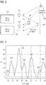
- FIG. 3 An overview of the signals travelling between the transceivers 110, 120 and the object is illustrated in Fig. 3 .
- a direct path 160 between the transceivers 110 and 120 i.e. a path between the transceivers 110 and 120 without obstacles.
- a reflection path 170 illustrating the reflection of the radiated electromagnetic waves (FTM packets) by the object 140.
- further paths 180 corresponding to reflections of the FTM packets from further objects in the vicinity of the transceivers 110, 120 and/or the object 140.
- the radio frequency receive signal 400 comprises a plurality of peaks.
- the first (temporal earliest) peak 410 relates to the direct path 160 in Fig. 3 , since the direct path 160 between the antennae 115, 125 of the transceivers 110, 120 is the shortest path.
- the second peak 420 is related to the reflection path 170 in Fig. 3 .
- the second peak 420 has the greatest amplitude since the antennae 115, 125 are oriented towards the object 140, so that a main portion of the radiated electromagnetic energy is radiated towards the object 140.
- the electromagnetic wave reflected by the object 140 comprises the most energy compared to the other components of the radio frequency signal 400.
- the peaks 430, 440, 450 and 460 are related to further paths 180 in Fig. 3 , i.e. to reflections of the transmitted FTM packet from objects other than the object 140.
- the reception time of the reflected component of the radio frequency receive signal 400 may be determined.
- FTM algorithms may resolve the individual peaks of the radio frequency receive signal 400.
- the reception time of the reflected component of the radio frequency receive signal 400 may be determined via a conventional FTM algorithm.
- FTM algorithms cannot resolve the individual peaks of the radio frequency receive signal 400 anymore. Therefore, a correction may be determined (calculated) in parallel using another algorithm for determining the reception time (ToA) such as, e.g., the MUSIC algorithm.
- the range (distance) between one of the antennae 115, 125 and the object is determined, i.e. according to above expression (1).
- the ToA for each antennae 115, 125 needs to be done according to correct peak timing.
- An FTM algorithm may use the WiGig good special separation to select the strongest peak, assuming energy was focused towards the obstacle before the measurement. For Wi-Fi this is not possible so that the exact peak timing is determined with oversampling (as explained above) and a fine time correction is added to the ToA value.
- Mapping the entire environment may be done, e.g., mechanically by a rotator, or electrically by beam forming using an array of antennas.
- the apparatuses/arrangements described above may comprise additional components/elements such as, e.g. switches, (external) power amplifiers or low-noise amplifiers.
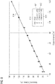
- distances may be determined with an accuracy of centimeters. This is evident from the comparison illustrated in Fig. 6 between real distances and distances measured by an example of an apparatus according to one or more aspects of the proposed architecture or one or more examples described above.
- the abscissa denotes the real distance between the antenna system of the transceivers and the object.
- the ordinate denotes the measured distance.
- line 610 illustrates ideal measurements without any errors.
- FIG. 7 schematically illustrates an example of a mobile device 700 (e.g. mobile phone, smartphone, tablet-computer, or laptop) comprising an apparatus 710 for measuring a distance to an object (not illustrated) according to an example described herein. Further illustrated is an antenna system 720 of the apparatus 710 for radiating the first radio frequency signal and the second radio frequency signal towards the object. Additionally, the antenna system 720 may be used for receiving the reflected components of the first and/or the second radio frequency signals which were reflected by the object. To this end, mobile device may be provided with radar functionality.
- a mobile device 700 e.g. mobile phone, smartphone, tablet-computer, or laptop
- an antenna system 720 of the apparatus 710 for radiating the first radio frequency signal and the second radio frequency signal towards the object.
- the antenna system 720 may be used for receiving the reflected components of the first and/or the second radio frequency signals which were reflected by the object.
- mobile device may be provided with radar functionality.
- the method 800 comprises transmitting 802 a first radio frequency signal by a first transceiver and transmitting 804, by a second transceiver, a second radio frequency signal in response to receiving the first radio frequency signal. Additionally, the method 800 comprises determining (calculating) 806 the distance to the object based on a transmission time of the first radio frequency signal and a reception time, at the first transceiver, of a reflected component of the second radio frequency signal that is reflected by the object.
- the method may comprise one or more additional optional features corresponding to one or more aspects of the proposed concept or one or more examples described above.
- the apparatus for measuring a distance to an object may be based on commercial chips without any changes of the same. Therefore, the solution may be very accessible and cheap for the mass market, since it does not require a dedicated hardware solution.
- the above described FTM based approach using at least two chips may be much simpler to implement than conventional radar, so that a lot of technological challenges in legacy radars using concurrent transmission and reception may be overcome.
- the proposed architecture may be used for high distance ranges that are required for automotive applications or drones, if the two transceivers are implemented in different semiconductor chips.
- the proposed distance measurement is not limited to mobile devices.
- the proposed distance measurement may be used for any kind of radar or radar-like application.
- the proposed distance measurement may be used for automotive applications, drones, security applications, autonomous machine applications, mapping applications, virtual reality applications, 3D scanning applications, or medical applications.
- some examples further relate to a vehicle (e.g. a car, a truck, a motorcycle, an airplane, a ship, a drone, a helicopter, a bike, or a scooter) comprising an apparatus for determining a distance to an object according to one or more aspects of the proposed architecture or one or more examples described above.
- a vehicle e.g. a car, a truck, a motorcycle, an airplane, a ship, a drone, a helicopter, a bike, or a scooter
- a scooter comprising an apparatus for determining a distance to an object according to one or more aspects of the proposed architecture or one or more examples described above.
- the vehicle may further comprise a control circuit configured to control an autonomous movement of the vehicle based on a distance to an object in the vehicle's surrounding which is determined by the apparatus.
- the apparatus may provide distance information used for autonomous movement driving of the vehicle (e.g. for autonomous driving of a car).
- a medical device comprising an apparatus for determining a distance to an object according to one or more aspects of the proposed architecture or one or more examples described above.
- the apparatus may be used in a medical device for medical imaging, patient motion monitoring, or for remote vital signs monitoring (e.g. cardiac and respiratory motion).
- a functional block denoted as "means for " performing a certain function may refer to a circuit that is configured to perform a certain function.
- a "means for s.th.” may be implemented as a "means configured to or suited for s.th.”, such as a device or a circuit configured to or suited for the respective task.
- Functions of various elements shown in the figures may be implemented in the form of dedicated hardware, such as “a signal provider”, “a signal processing unit”, “a processor”, “a controller”, etc. as well as hardware capable of executing software in association with appropriate software.
- a processor the functions may be provided by a single dedicated processor, by a single shared processor, or by a plurality of individual processors, some of which or all of which may be shared.
- processor or “controller” is by far not limited to hardware exclusively capable of executing software, but may include digital signal processor (DSP) hardware, network processor, application specific integrated circuit (ASIC), field programmable gate array (FPGA), read only memory (ROM) for storing software, random access memory (RAM), and nonvolatile storage.
- DSP digital signal processor
- ASIC application specific integrated circuit
- FPGA field programmable gate array
- ROM read only memory
- RAM random access memory
- nonvolatile storage Other hardware, conventional and/or custom, may also be included.
- a block diagram may, for instance, illustrate a high-level circuit diagram implementing the principles of the disclosure.
- a flow chart, a flow diagram, a state transition diagram, a pseudo code, and the like may represent various processes, operations or steps, which may, for instance, be substantially represented in computer readable medium and so executed by a computer or processor, whether or not such computer or processor is explicitly shown.
- Methods disclosed in the specification or in the claims may be implemented by a device having means for performing each of the respective acts of these methods.
Description
- Examples relate to measuring a distance to an object. In particular, examples relate to an apparatus and a method for determining a distance to an object.
- Radar systems are becoming more and more common in commercial use cases (e.g. autonomous driving, autonomous machines, drones, mapping, etc.). Moving from defense use cases to commercial use cases requires radar systems with reduced costs, power consumption and size. For example, radar systems are proposed in documents
US 2005/0046606 A1 ,DE 10 2013 008 953 A1US 2013/0162461 A1 . - Hence, there may be a desire for improved radar techniques.
- Some examples of apparatuses and/or methods will be described in the following by way of example only, and with reference to the accompanying figures, in which
-
Fig. 1 illustrates an example of an apparatus for determining a distance to an object; -
Fig. 2 illustrates an example of a distance determination; -
Fig. 3 illustrates an example of radio frequency signals present during the determination procedure; -
Fig. 4 illustrates an example of a radio frequency signal received by one the transceivers; -
Fig. 5 illustrates an example of a Fine Timing Measurement (FTM) scheme; -
Fig. 6 illustrates a comparison between real distances and distances determined by an example of an apparatus for determining a distance to an object; -
Fig. 7 illustrates an example of a user equipment comprising an apparatus for determining a distance to an object; and -
Fig. 8 illustrates a flowchart of an example of a method for determining a distance to an object. - Various examples will now be described more fully with reference to the accompanying drawings in which some examples are illustrated. In the figures, the thicknesses of lines, layers and/or regions may be exaggerated for clarity.
- Accordingly, while further examples are capable of various modifications and alternative forms, some particular examples thereof are shown in the figures and will subsequently be described in detail. However, this detailed description does not limit further examples to the particular forms described. Further examples may cover all modifications, equivalents, and alternatives falling within the scope of the disclosure. Like numbers refer to like or similar elements throughout the description of the figures, which may be implemented identically or in modified form when compared to one another while providing for the same or a similar functionality.
- It will be understood that when an element is referred to as being "connected" or "coupled" to another element, the elements may be directly connected or coupled or via one or more intervening elements. If two elements A and B are combined using an "or", this is to be understood to disclose all possible combinations, i.e. only A, only B as well as A and B. An alternative wording for the same combinations is "at least one of A and B". The same applies for combinations of more than 2 Elements.
- The terminology used herein for the purpose of describing particular examples is not intended to be limiting for further examples. Whenever a singular form such as "a," "an" and "the" is used and using only a single element is neither explicitly or implicitly defined as being mandatory, further examples may also use plural elements to implement the same functionality.
- Likewise, when a functionality is subsequently described as being implemented using multiple elements, further examples may implement the same functionality using a single element or processing entity. It will be further understood that the terms "comprises," "comprising," "includes" and/or "including," when used, specify the presence of the stated features, integers, steps, operations, processes, acts, elements and/or components, but do not preclude the presence or addition of one or more other features, integers, steps, operations, processes, acts, elements, components and/or any group thereof.
- Unless otherwise defined, all terms (including technical and scientific terms) are used herein in their ordinary meaning of the art to which the examples belong.
-
Fig. 1 illustrates anapparatus 100 for determining (measuring) a distance to anobject 140. Theapparatus 100 comprises afirst transceiver 110 configured to transmit a firstradio frequency signal 111. Further, theapparatus 100 comprises asecond transceiver 120 configured to transmit a secondradio frequency signal 112 in response to receiving the firstradio frequency signal 111. Theapparatus 100 additionally comprises aprocessing circuit 130 configured to determine (calculate) the distance to theobject 140 based on a transmission time of the firstradio frequency signal 111 and a reception time, at thefirst transceiver 120, of areflected component 113 of the second radio frequency signal that is reflected by theobject 140. - The
apparatus 100 may enable to determining (calculate) the distance of theapparatus 100 to theobject 140 since the reception time of thereflected component 113 of the second radio frequency signal is used for the determination. Accordingly, the time-of-flight of the secondradio frequency signal 112 from thesecond transceiver 120 via theobject 140 to thefirst transceiver 110 may be determined, and the distance of theapparatus 100 to theobject 140 may be determined therefrom. - A carrier frequency of the first
radio frequency signal 111 and/or the secondradio frequency signal 112 may be, e.g., about 700 MHz or more, 5 GHz or more, 10 GHz or more, 20 GHz or more, or 50 GHz or more. - In some examples, the first
radio frequency signal 111 and the secondradio frequency signal 112 are compliant to the IEEE 802.11 family of standards of the Institute of Electrical and Electronics Engineers. That is, thefirst transceiver 110 and/or thesecond transceiver 120 may be Wireless Local Area Network (WLAN) transceivers (e.g. Wi-Fi or WiGig compliant). Accordingly, the firstradio frequency signal 111 and the secondradio frequency signal 112 may be WLAN signals. WLAN transceivers for theapparatus 100 in the present disclosure may allow to use commercially available WLAN transceivers for radar or other applications. - In the present disclosure, the proposed distance measurement is not limited to WLAN transceivers. Any transceiver suitable to transmit and receive radio frequency signals may also be used.
- The
object 140 may include any kind of object. An object stationary to theapparatus 100 as well as an object moving relative to theapparatus 100. A metallic object (e.g. a steel post) as well as a non-metallic object (e.g. a plastic). A conducting object (e.g. a power line) as well as a non-conducting object (an isolator). A solid object (e.g. a wall) as well as a soft object (e.g. tissue). A biological object (e.g. tissue, a human being or an animal) as well as a non-biological object (e.g. a stone or a wall). - The
apparatus 100 may, e.g., further comprise an antenna system (not illustrated) configured to radiate the firstradio frequency signal 111 and the secondradio frequency signal 112 towards theobject 140. That is, thefirst transceiver 110 and thesecond transceiver 120 share a single antenna system for radiating radio frequency signals towards the object. - For example, the antenna system may comprise a first antenna element configured to radiate the first
radio frequency signal 111 into the environment, and a second antenna element configured to radiate the secondradio frequency signal 112 into the environment. The first antenna element and the second antenna element are oriented towards theobject 140. That is, the antenna system may comprise individual antenna elements associated to the transceivers, wherein all the antenna elements are directed towards theobject 140. - The antenna system may additionally comprise an actuator configured to adjust an orientation of the first and second antenna elements. This may allow to orient the antenna elements towards different objects or to determine the distance to a moving object. For example, the actuator may be rotator which rotates the antenna elements around a defined axis of rotation. Accordingly, distances to objects around the whole axis of rotation may be determined.
- In alternative examples, the antenna system may comprise an antenna array configured to radiate the first
radio frequency signal 111 and the secondradio frequency signal 112 into the environment. A main lobe of the antenna array's radiation pattern is oriented towards theobject 140. That is, beam forming may be used to focus the firstradio frequency signal 111 and the secondradio frequency signal 112 on theobject 140 by means of the antenna array. - The
processing circuit 130 may be further configured to determine the distance to theobject 140 based on a transmission time of the secondradio frequency signal 112 and a reception time, at thesecond transceiver 120, of areflected component 114 of the first radio frequency signal that is reflected by theobject 140. By taking into account these additional information, a round-trip time including the reflection at theobject 140 may be determined (i.e. the time it takes for the firstradio frequency signal 111 to be sent to thesecond transceiver 120 via theobject 140 plus the length of time it takes for the secondradio frequency signal 112 to be sent to thefirst transceiver 110 via the object 140). - For example, the
processing circuit 130 may be configured to determine the distance to theobject 140 based on a relationship between the speed of light, a first difference between the transmission time of the firstradio frequency signal 111 and the reception time, at thefirst transceiver 110, of the reflectedcomponent 113 of the second radio frequency signal, a second difference between the transmission time of the secondradio frequency signal 112 and the reception time, at thesecond transceiver 120, of the reflectedcomponent 114 of the first radio frequency signal, a difference between the first difference and the second difference, and a constant. - The
processing circuit 130 may be configured to determine the distance to theobject 140, e.g., based on expression which is mathematically correspondent to:
- The first
radio frequency signal 111 and the secondradio frequency signal 112 may, in some examples, be signals of a burst of a Fine Time Measurement (FTM) according to the IEEE 802.11 family of standards of the Institute of Electrical and Electronics Engineers. - FTM enables a resolution in the range of centimeters. In a regular FTM (as illustrated in
Fig. 5 ) for determining a distance between two transceivers, the transceivers (and their antennas) face each other. The first transceiver sends an FTM request to the second transceiver, which acknowledges the receipt. After that, the second transceiver sends a first FTM packet, which is acknowledged by the first transceiver. This procedure is repeated several times during a burst, wherein the FTM packets of the first transceiver comprise information on the Time of Departure (ToD) of the previous FTM frame and information on the Time of Arrival (ToA) of the acknowledgement of the previous FTM packet. In this configuration, both devices measure the direct path between each other. - In contrast to that, the antenna system of both the first and
second transceivers object 140 as illustrated inFig. 1 and an FTM between the first andsecond transceivers second transceivers object 140 may be determined with high accuracy using the reflected component of the first and/or the secondradio frequency signal 111, 112 (instead of the component of the first and/or the secondradio frequency signal apparatus 100 to theobject 140 may be determined with the high accuracy of the FTM. - The
processing circuit 130 may, e.g., be configured to select a reception time of a signal peak of the received first radio frequency signal having the greatest amplitude as the reception time of the reflectedcomponent 114 of the first radio frequency signal. Also, theprocessing circuit 130 may be configured to select a reception time of a signal peak of the received second radio frequency signal having the greatest amplitude as the reception time of the reflectedcomponent 113 of the second radio frequency signal. If the first/secondradio frequency signal 111/ 112 is focused on theobject 140, the highest peak in the signal received at the first/second transceiver object 140. Hence, the reflected component of the received signal may be determined by selecting the highest peak of the receive signal (details will be explained in connection withFigs. 3 and 4 ). - For radio frequency signals having a carrier frequency of 50 GHz or more (e.g. radio frequency signals which are compliant to WiGig), the individual peaks of the received signal at one of the first and the
second transceivers processing circuit 130 may be configured to determine a reception time of the received second radio frequency signal using an algorithm for a FTM according to the IEEE 802.11 family of standards of the Institute of Electrical and Electronics Engineers. - Further, the
processing circuit 130 may be configured to determine, using another algorithm (e.g. MUSIC algorithm or ESPRIT algorithm), a correction value for the reception time of the received second radio frequency signal based on the received second radio frequency signal, and to determine the reception time of the reflectedcomponent 113 of the second radio frequency signal by combining the reception time of the received second radio frequency and the correction value. The determination of the correction value and the determination of the reception time of the received second radio frequency signal may be done in parallel in order to speed up the determination of the reception time of the reflectedcomponent 113 of the second radio frequency signal. - Further, the
apparatus 100 may comprise a first semiconductor chip comprising thefirst transceiver 110, and a second semiconductor chip comprising thesecond transceiver 120. In other words, thefirst transceiver 110 and thesecond transceiver 120 may be arranged on different semiconductor chips. This may allow to increase the power of the first and/or the secondradio frequency signal apparatus 100 and theobject 140 may be measured by theapparatus 100. - Generally speaking, some examples presented herein relate to a means for determining a distance to an object. The means comprises a means for transmitting a first radio frequency signal, and a means for transmitting a second radio frequency signal in response to receiving the first radio frequency signal. Additionally, the means comprises a means for determining the distance to the object based on a transmission time of the first radio frequency signal and a reception time, at the means for transmitting the first radio frequency signal, of a reflected component of the second radio frequency signal that is reflected by the object.
- The means for determining the distance to the object may be further configured to determine the distance to the object based on a transmission time of the second radio frequency signal and a reception time, at the means for transmitting the second radio frequency, of a reflected component of the first radio frequency signal that is reflected by the object.
- The means for determining a distance to an object may be implemented by an apparatus for determining a distance to an object described above or below (e.g.
Fig. 1 ). The means for transmitting a first radio frequency signal may be implemented by a first transceiver described above or below (e.g.Fig. 1 ). The means for transmitting a second radio frequency signal may be implemented by a second transceiver described above or below (e.g.Fig. 1 ). The means for determining the distance to the object may be implemented by a processing circuit described above or below (e.g.Fig. 1 ). - An example of a distance measurement using FTM is illustrated in
Figs. 2 to 4 . Although the FTM procedure is described with respect to this example, any other round trip time procedure may be used. -
Fig. 2 illustrates an exemplary general concept. Twotransceivers antennae antennae object 140. Thetransceivers Fig. 2 . In the following, the FTM procedure which is performed between the twotransceivers - The
first transceiver 110 measures the transmission time (ToD) of the FTM packet (i.e. the first radio frequency signal) it sends via theantenna 115. The electromagnetic wave reaches theobject 140 and part of the energy returns back. - The
second transceiver 120 measures the reception time (ToA) of the returned electromagnetic wave (i.e. the reflected component of the first radio frequency signal that is reflected by the object 140). Further, thesecond transceiver 120 transmits back an FTM packet (i.e. the second radio frequency signal) as defined in the FTM protocol, and measure the ToD. Accordingly, thefirst transceiver 110 computes the ToA of the electromagnetic wave that was returned from theobject 140, and not the ToA related to the direct path between thetransceivers - An overview of the signals travelling between the
transceivers Fig. 3 . As illustrated inFig. 3 , there is adirect path 160 between thetransceivers 110 and 120 (i.e. a path between thetransceivers reflection path 170 illustrating the reflection of the radiated electromagnetic waves (FTM packets) by theobject 140. Additionally, there may be one or morefurther paths 180 corresponding to reflections of the FTM packets from further objects in the vicinity of thetransceivers object 140. - An example of a temporal course of a resulting radio frequency receive
signal 400 at one of thetransceivers Fig. 4 . The radio frequency receivesignal 400 comprises a plurality of peaks. The first (temporal earliest)peak 410 relates to thedirect path 160 inFig. 3 , since thedirect path 160 between theantennae transceivers second peak 420 is related to thereflection path 170 inFig. 3 . Thesecond peak 420 has the greatest amplitude since theantennae object 140, so that a main portion of the radiated electromagnetic energy is radiated towards theobject 140. Accordingly, the electromagnetic wave reflected by theobject 140 comprises the most energy compared to the other components of theradio frequency signal 400. Thepeaks further paths 180 inFig. 3 , i.e. to reflections of the transmitted FTM packet from objects other than theobject 140. - Accordingly, by selecting the peak of the radio frequency receive
signal 400 having the greatest amplitude, the reception time of the reflected component of the radio frequency receivesignal 400 may be determined. As discussed above, for radio frequency signals compliant to WiGig (i.e. signals having a carrier frequency of 50 GHz or more), FTM algorithms may resolve the individual peaks of the radio frequency receivesignal 400. Accordingly, the reception time of the reflected component of the radio frequency receivesignal 400 may be determined via a conventional FTM algorithm. For radio frequency signals compliant to Wi-Fi (i.e. signals having a carrier frequency of up to 10 GHz), FTM algorithms cannot resolve the individual peaks of the radio frequency receivesignal 400 anymore. Therefore, a correction may be determined (calculated) in parallel using another algorithm for determining the reception time (ToA) such as, e.g., the MUSIC algorithm. - The range between both
antennae object 140 is then determined according to
- By dividing the range r by two, the range (distance) between one of the
antennae - In order to determine the correct distance, the ToA for each
antennae 
first transceiver 110, and T correction2 denoting the fine time correction (correction value) for the arrival time of the first radio frequency signal at thesecond transceiver 120. - Mapping the entire environment may be done, e.g., mechanically by a rotator, or electrically by beam forming using an array of antennas. Further, the apparatuses/arrangements described above may comprise additional components/elements such as, e.g. switches, (external) power amplifiers or low-noise amplifiers.
- Using distance measurement according to the above example, distances may be determined with an accuracy of centimeters. This is evident from the comparison illustrated in
Fig. 6 between real distances and distances measured by an example of an apparatus according to one or more aspects of the proposed architecture or one or more examples described above. - The abscissa denotes the real distance between the antenna system of the transceivers and the object. The ordinate denotes the measured distance. As a reference,
line 610 illustrates ideal measurements without any errors. - Three
measurement series Fig. 6 that the measurement points are very close toline 610. Especially for distances greater than 30 cm, the accuracy is very high. - An example of an implementation using an apparatus for measuring a distance to an object according to one or more aspects of the proposed architecture or one or more examples described above is illustrated in
Fig. 7. Fig. 7 schematically illustrates an example of a mobile device 700 (e.g. mobile phone, smartphone, tablet-computer, or laptop) comprising anapparatus 710 for measuring a distance to an object (not illustrated) according to an example described herein. Further illustrated is anantenna system 720 of theapparatus 710 for radiating the first radio frequency signal and the second radio frequency signal towards the object. Additionally, theantenna system 720 may be used for receiving the reflected components of the first and/or the second radio frequency signals which were reflected by the object. To this end, mobile device may be provided with radar functionality. - An example of a
method 800 for determining a distance to an object is illustrated by means of a flowchart inFig. 8 . Themethod 800 comprises transmitting 802 a first radio frequency signal by a first transceiver and transmitting 804, by a second transceiver, a second radio frequency signal in response to receiving the first radio frequency signal. Additionally, themethod 800 comprises determining (calculating) 806 the distance to the object based on a transmission time of the first radio frequency signal and a reception time, at the first transceiver, of a reflected component of the second radio frequency signal that is reflected by the object. - More details and aspects of the method are mentioned in connection with the proposed concept or one or more examples described above (e.g.
Figs. 1 - 6 ). The method may comprise one or more additional optional features corresponding to one or more aspects of the proposed concept or one or more examples described above. - There may be a number of benefits for the proposed architecture compared to other solutions: The apparatus for measuring a distance to an object may be based on commercial chips without any changes of the same. Therefore, the solution may be very accessible and cheap for the mass market, since it does not require a dedicated hardware solution. The above described FTM based approach using at least two chips may be much simpler to implement than conventional radar, so that a lot of technological challenges in legacy radars using concurrent transmission and reception may be overcome. The proposed architecture may be used for high distance ranges that are required for automotive applications or drones, if the two transceivers are implemented in different semiconductor chips.
- The proposed distance measurement is not limited to mobile devices. The proposed distance measurement may be used for any kind of radar or radar-like application. For example, the proposed distance measurement may be used for automotive applications, drones, security applications, autonomous machine applications, mapping applications, virtual reality applications, 3D scanning applications, or medical applications.
- Therefore, some examples further relate to a vehicle (e.g. a car, a truck, a motorcycle, an airplane, a ship, a drone, a helicopter, a bike, or a scooter) comprising an apparatus for determining a distance to an object according to one or more aspects of the proposed architecture or one or more examples described above.
- The vehicle may further comprise a control circuit configured to control an autonomous movement of the vehicle based on a distance to an object in the vehicle's surrounding which is determined by the apparatus. In other words, the apparatus may provide distance information used for autonomous movement driving of the vehicle (e.g. for autonomous driving of a car).
- Other examples relate to a medical device comprising an apparatus for determining a distance to an object according to one or more aspects of the proposed architecture or one or more examples described above. For example, the apparatus may be used in a medical device for medical imaging, patient motion monitoring, or for remote vital signs monitoring (e.g. cardiac and respiratory motion).
- The scope of the invention is defined in the independent claims .
- The description and drawings merely illustrate the principles of the disclosure. Furthermore, all examples recited herein are principally intended expressly to be only for pedagogical purposes to aid the reader in understanding the principles of the disclosure and the concepts contributed by the inventor(s) to furthering the art. All statements herein reciting principles, aspects, and examples of the disclosure, as well as specific examples thereof, are intended to encompass equivalents thereof.
- A functional block denoted as "means for ..." performing a certain function may refer to a circuit that is configured to perform a certain function. Hence, a "means for s.th." may be implemented as a "means configured to or suited for s.th.", such as a device or a circuit configured to or suited for the respective task.
- Functions of various elements shown in the figures, including any functional blocks labeled as "means", "means for providing a sensor signal", "means for generating a transmit signal.", etc., may be implemented in the form of dedicated hardware, such as "a signal provider", "a signal processing unit", "a processor", "a controller", etc. as well as hardware capable of executing software in association with appropriate software. When provided by a processor, the functions may be provided by a single dedicated processor, by a single shared processor, or by a plurality of individual processors, some of which or all of which may be shared. However, the term "processor" or "controller" is by far not limited to hardware exclusively capable of executing software, but may include digital signal processor (DSP) hardware, network processor, application specific integrated circuit (ASIC), field programmable gate array (FPGA), read only memory (ROM) for storing software, random access memory (RAM), and nonvolatile storage. Other hardware, conventional and/or custom, may also be included.
- A block diagram may, for instance, illustrate a high-level circuit diagram implementing the principles of the disclosure. Similarly, a flow chart, a flow diagram, a state transition diagram, a pseudo code, and the like may represent various processes, operations or steps, which may, for instance, be substantially represented in computer readable medium and so executed by a computer or processor, whether or not such computer or processor is explicitly shown. Methods disclosed in the specification or in the claims may be implemented by a device having means for performing each of the respective acts of these methods.
- It is to be understood that the disclosure of multiple acts, processes, operations, steps or functions disclosed in the specification or claims may not be construed as to be within the specific order, unless explicitly or implicitly stated otherwise, for instance for technical reasons. Therefore, the disclosure of multiple acts or functions will not limit these to a particular order unless such acts or functions are not interchangeable for technical reasons. Furthermore, in some examples a single act, function, process, operation or step may include or may be broken into multiple sub-acts, -functions, -processes, -operations or -steps, respectively. Such sub acts may be included and part of the disclosure of this single act unless explicitly excluded.
Claims (11)
- An apparatus (100) for determining a distance of the apparatus (100) to an object (140), comprising:a first transceiver (110) configured to transmit a first radio frequency signal (111);a second transceiver (120) configured to transmit a second radio frequency signal (112) in response to receiving a reflected component (114) of the first radio frequency signal (111) that is reflected by the object (140), wherein the first transceiver (110) is further configured to receive a reflected component (114) of the second radio frequency signal that is reflected by the object (140);an antenna system configured to radiate the first radio frequency signal (111) and the second radio frequency signal (112) towards the object (140); anda processing circuit (130) configured to determine the distance of the apparatus (100) to the object (140) based on a relationship between the speed of light, a difference between a first difference and a second difference, and a constant, wherein the first difference is between a transmission time of the first radio frequency signal (111) and a reception time, at the first transceiver (110), of the reflected component (113) of the second radio frequency signal, andwherein the second difference is between a transmission time of the second radio frequency signal (112) and a reception time, at the second transceiver (120), of the reflected component (114) of the first radio frequency signal,characterised in that the first radio frequency signal (111) and the second radio frequency signal (112) are compliant to the IEEE 802.11 family of standards of the Institute of Electrical and Electronics Engineers.
- The apparatus of claim 1, wherein the antenna system comprises:a first antenna element (115) configured to radiate the first radio frequency signal (111) into the environment; anda second antenna element (125) configured to radiate the second radio frequency signal (112) into the environment,wherein the first antenna clement (115) and the second antenna clement (125) arc oriented towards the object (140).
- The apparatus of claim 2, wherein the antenna system further comprises:
an actuator configured to adjust an orientation of the first and second antenna elements (115, 125). - The apparatus of claim 1, wherein the antenna system comprises:
an antenna array configured to radiate the first radio frequency signal (111) and the second radio frequency signal (112) into the environment, wherein a main lobe of the antenna array's radiation pattern is oriented towards the object (140). - The apparatus of any of the preceding claims, wherein the processing circuit (130) is configured to:determine a reception time of the received second radio frequency signal using a first algorithm for a Fine Time Measurement according to the IEEE 802.11 family of standards of the Institute of Electrical and Electronics Engineers;determine, using a second algorithm, a correction value for the reception time of the received second radio frequency signal based on the received second radio frequency signal; anddetermine the reception time of the reflected component (113) of the second radio frequency signal by combining the reception time of the received second radio frequency and the correction value.
- The apparatus of any of claims 1 to 4, wherein the processing circuit (130) is configured to:select a reception time of a signal peak of the received first radio frequency signal having the greatest amplitude as the reception time of the reflected component of the first radio frequency signal, orselect a reception time of a signal peak of the received second radio frequency signal having the greatest amplitude as the reception time of the reflected component of the second radio frequency signal.
- The apparatus of any of the preceding claims, wherein a carrier frequency of the first radio frequency signal (111) or the second radio frequency signal (112) is 700 MHz or more.
- The apparatus of any of the preceding claims, wherein a carrier frequency of the first radio frequency signal (111) or the second radio frequency signal (112) is 50 GHz or more.
- The apparatus of any of the preceding claims, wherein the first radio frequency signal (111) and the second radio frequency signal (112) are signals of a burst of a Fine Time Measurement according to the IEEE 802.11 family of standards of the Institute of Electrical and Electronics Engineers.
- The apparatus of any of the preceding claims, further comprising:a first semiconductor chip comprising the first transceiver (110); anda second semiconductor chip comprising the second transceiver (120).
- A method (800) for determining a distance to an object, comprising:transmitting (802) a first radio frequency signal by a first transceiver;receiving, by a second transceiver, a reflected component of the first radio frequency signal that is reflected by the object;transmitting (804), by the second transceiver, a second radio frequency signal in response to receiving the reflected component of the first radio frequency signal, wherein the first radio frequency signal and the second radio frequency signal are radiated towards the object by an antenna system;receiving, by the first transceiver, a reflected component of the second radio frequency signal that is reflected by the object; anddetermining (806) the distance to the object based on a relationship between the speed of light, a difference between a first difference and a second difference, and a constant, wherein the first difference is between a transmission time of the first radio frequency signal and a reception time, at the first transceiver, of the reflected component of the second radio frequency signal, and wherein the second difference is between a transmission time of the second radio frequency signal and a reception time, at the second transceiver, of the reflected component of the first radio frequency signal,characterised in that the first radio frequency signal and the second radio frequency signal are compliant to the IEEE 802.11 family of standards of the Institute of Electrical and Electronics Engineers.
Priority Applications (3)
| Application Number | Priority Date | Filing Date | Title |
|---|---|---|---|
| EP17172842.1A EP3407082B1 (en) | 2017-05-24 | 2017-05-24 | Apparatus and method for determining a distance to an object |
| US15/951,202 US10928479B2 (en) | 2017-05-24 | 2018-04-12 | Apparatus and method for determining a distance to an object |
| CN201810372032.2A CN108931767B (en) | 2017-05-24 | 2018-04-24 | Apparatus and method for determining distance to object |
Applications Claiming Priority (1)
| Application Number | Priority Date | Filing Date | Title |
|---|---|---|---|
| EP17172842.1A EP3407082B1 (en) | 2017-05-24 | 2017-05-24 | Apparatus and method for determining a distance to an object |
Publications (2)
| Publication Number | Publication Date |
|---|---|
| EP3407082A1 EP3407082A1 (en) | 2018-11-28 |
| EP3407082B1 true EP3407082B1 (en) | 2021-06-23 |
Family
ID=58772780
Family Applications (1)
| Application Number | Title | Priority Date | Filing Date |
|---|---|---|---|
| EP17172842.1A Active EP3407082B1 (en) | 2017-05-24 | 2017-05-24 | Apparatus and method for determining a distance to an object |
Country Status (3)
| Country | Link |
|---|---|
| US (1) | US10928479B2 (en) |
| EP (1) | EP3407082B1 (en) |
| CN (1) | CN108931767B (en) |
Families Citing this family (8)
| Publication number | Priority date | Publication date | Assignee | Title |
|---|---|---|---|---|
| EP3707943B1 (en) * | 2017-11-06 | 2022-01-05 | Telefonaktiebolaget LM Ericsson (publ) | Method and apparatus for obstacle detection |
| DE102018117145A1 (en) * | 2018-07-16 | 2020-01-16 | Balluff Gmbh | Multi-zone proximity sensor and a method for measuring a distance of an object from the multi-zone proximity sensor |
| US10734709B2 (en) * | 2018-09-28 | 2020-08-04 | Qualcomm Incorporated | Common-radiator multi-band antenna system |
| US11194031B2 (en) * | 2018-11-27 | 2021-12-07 | Qualcomm Incorporated | Apparatus and techniques for 3D reconstruction with coordinated beam scan using millimeter wave radar |
| KR20200145066A (en) | 2019-06-20 | 2020-12-30 | 삼성전자주식회사 | Method for emproving the accuracy of a distance measurement and electronic device thereof |
| CN112825568B (en) * | 2019-11-20 | 2022-08-26 | 华为技术有限公司 | Method and device for positioning target object |
| KR20210093550A (en) | 2020-01-20 | 2021-07-28 | 삼성전자주식회사 | Object detection device and vehicle control system including the same |
| GB2601497A (en) * | 2020-12-01 | 2022-06-08 | Nordic Semiconductor Asa | Radio frequency distance determination |
Family Cites Families (27)
| Publication number | Priority date | Publication date | Assignee | Title |
|---|---|---|---|---|
| DE4439708A1 (en) * | 1994-11-05 | 1996-05-09 | Bosch Gmbh Robert | Method for determining the position of a vehicle on a road |
| US6055042A (en) * | 1997-12-16 | 2000-04-25 | Caterpillar Inc. | Method and apparatus for detecting obstacles using multiple sensors for range selective detection |
| US6628227B1 (en) * | 2002-07-23 | 2003-09-30 | Ford Global Technologies, Llc | Method and apparatus for determining a target vehicle position from a source vehicle using a radar |
| US20040203877A1 (en) * | 2002-10-17 | 2004-10-14 | Golden Stuart A. | Two-way ranging techniques |
| JP4293865B2 (en) * | 2003-09-02 | 2009-07-08 | 富士通テン株式会社 | Object detection device |
| GB0325622D0 (en) * | 2003-11-03 | 2003-12-10 | Cambridge Consultants | System for determining positional information |
| KR101182900B1 (en) * | 2004-11-15 | 2012-09-13 | 나노트론 테크놀로지스 게엠바하 | Symmetrical multipath method for determining the distance between two transceivers |
| US7423576B2 (en) * | 2006-07-24 | 2008-09-09 | Mitsubishi Electric Research Laboratories, Inc. | System and method for radar tracking using communications packets |
| US20080248808A1 (en) * | 2007-04-05 | 2008-10-09 | Farshid Alizadeh-Shabdiz | Estimation of position, speed and bearing using time difference of arrival and received signal strength in a wlan positioning system |
| US8515454B2 (en) * | 2007-07-23 | 2013-08-20 | Nxp B.V. | Method of determining the location of a node in a distributed wireless sensor and actuator network |
| US8823577B2 (en) * | 2009-12-23 | 2014-09-02 | Itrack, Llc | Distance separation tracking system |
| DE102010045657A1 (en) * | 2010-09-17 | 2012-03-22 | Wabco Gmbh | Environment monitoring system for a vehicle |
| US8723720B2 (en) * | 2011-05-03 | 2014-05-13 | Harris Corporation | Wireless location detection and/or tracking device and associated methods |
| WO2013093550A1 (en) * | 2011-12-19 | 2013-06-27 | Nokia Corporation | An apparatus and associated methods for switching between antennas in a multi-antenna receiver |
| US9213093B2 (en) * | 2012-12-21 | 2015-12-15 | Qualcomm Incorporated | Pairwise measurements for improved position determination |
| DE102013008953B4 (en) * | 2013-05-27 | 2017-01-05 | Volkswagen Aktiengesellschaft | Method for operating a radar device of a vehicle, in particular of a motor vehicle, and radar device for a vehicle, in particular a motor vehicle |
| DE102014104273A1 (en) * | 2014-03-26 | 2015-10-01 | Friedrich-Alexander-Universität Erlangen-Nürnberg | Method in a radar system, radar system or apparatus of a radar system |
| WO2016044627A1 (en) * | 2014-09-17 | 2016-03-24 | Greina Technologies, Inc. | Measurement accuracy classifier for high-resolution ranging |
| JP6442225B2 (en) * | 2014-10-22 | 2018-12-19 | 株式会社デンソー | Object detection device |
| JP6474228B2 (en) * | 2014-10-22 | 2019-02-27 | 株式会社デンソー | Object detection device |
| JP6404679B2 (en) * | 2014-10-22 | 2018-10-10 | 株式会社デンソー | Object detection device |
| JP2016080641A (en) * | 2014-10-22 | 2016-05-16 | 株式会社デンソー | Object detector |
| US10938585B2 (en) * | 2015-03-16 | 2021-03-02 | Qualcomm Incorporated | Location and range determination using broadcast messages |
| US9907042B2 (en) * | 2015-06-15 | 2018-02-27 | Intel IP Corporation | Apparatus, system and method of determining a time synchronization function (TSF) based on fine time measurement (FTM) messages |
| EP3153875A1 (en) * | 2015-10-06 | 2017-04-12 | Autoliv Development AB | A modular vehicle radar |
| WO2017091711A1 (en) * | 2015-11-25 | 2017-06-01 | Scott Technologies, Inc. | Indoor location and tracking system |
| US11255663B2 (en) * | 2016-03-04 | 2022-02-22 | May Patents Ltd. | Method and apparatus for cooperative usage of multiple distance meters |
-
2017
- 2017-05-24 EP EP17172842.1A patent/EP3407082B1/en active Active
-
2018
- 2018-04-12 US US15/951,202 patent/US10928479B2/en active Active
- 2018-04-24 CN CN201810372032.2A patent/CN108931767B/en active Active
Also Published As
| Publication number | Publication date |
|---|---|
| CN108931767A (en) | 2018-12-04 |
| US10928479B2 (en) | 2021-02-23 |
| US20180341000A1 (en) | 2018-11-29 |
| CN108931767B (en) | 2024-04-16 |
| EP3407082A1 (en) | 2018-11-28 |
Similar Documents
| Publication | Publication Date | Title |
|---|---|---|
| EP3407082B1 (en) | Apparatus and method for determining a distance to an object | |
| EP3986018A1 (en) | Sensing measurement method and device | |
| CN108139473B (en) | Angle and position sensing using antenna arrays | |
| US10823841B1 (en) | Radar imaging on a mobile computing device | |
| KR102495782B1 (en) | New Vehicle Radar Using 3D Printed Luneburg Lenses | |
| US11031978B2 (en) | Detection and ranging using multi-radio mobile devices | |
| US7948431B2 (en) | Radiobased locating system provided with a synthetic aperture | |
| US9470782B2 (en) | Method and apparatus for increasing angular resolution in an automotive radar system | |
| US8116350B1 (en) | Ultrawideband asynchronous tracking system and method | |
| JP2019512081A (en) | Radar system including an antenna structure for transmitting and receiving electromagnetic radiation | |
| US9213095B2 (en) | Combined direction finder and radar system, method and computer program product | |
| US11614532B2 (en) | Multistatic radar utilizing 5G | |
| EP3394633B1 (en) | Device in a car for communicating with at least one neighboring device, corresponding method and computer program product. | |
| CN113655437A (en) | Ranging method, ranging apparatus, and storage medium | |
| EP3327463B1 (en) | Electromagnetic wave imaging system and antenna array signal correction method | |
| JP2009270863A (en) | Bistatic radar system | |
| EP3259945B1 (en) | Communication device, access node and methods thereof | |
| Kanhere et al. | Millimeter wave position location using multipath differentiation for 3GPP using field measurements | |
| US20220321164A1 (en) | Angle information estimation of ultra-wideband wireless signals | |
| US20220069860A1 (en) | Static target detection for rf sensing in full-duplex communication systems | |
| CN112689242A (en) | Method and device for searching target equipment, equipment and storage medium | |
| WO2022022137A1 (en) | Imaging method and apparatus, and radar system, electronic device and storage medium | |
| US20240036183A1 (en) | Radar method and radar system for a phase-coherent analysis | |
| Gong et al. | Millimeter-Wave Localization of Multiple Targets Using TDOA and Wideband Frequency Modulation | |
| Li et al. | Target location based on time focusing of time-reveral retransmitting signals |
Legal Events
| Date | Code | Title | Description |
|---|---|---|---|
| PUAI | Public reference made under article 153(3) epc to a published international application that has entered the european phase |
Free format text: ORIGINAL CODE: 0009012 |
|
| STAA | Information on the status of an ep patent application or granted ep patent |
Free format text: STATUS: THE APPLICATION HAS BEEN PUBLISHED |
|
| AK | Designated contracting states |
Kind code of ref document: A1 Designated state(s): AL AT BE BG CH CY CZ DE DK EE ES FI FR GB GR HR HU IE IS IT LI LT LU LV MC MK MT NL NO PL PT RO RS SE SI SK SM TR |
|
| AX | Request for extension of the european patent |
Extension state: BA ME |
|
| STAA | Information on the status of an ep patent application or granted ep patent |
Free format text: STATUS: REQUEST FOR EXAMINATION WAS MADE |
|
| 17P | Request for examination filed |
Effective date: 20190528 |
|
| RBV | Designated contracting states (corrected) |
Designated state(s): AL AT BE BG CH CY CZ DE DK EE ES FI FR GB GR HR HU IE IS IT LI LT LU LV MC MK MT NL NO PL PT RO RS SE SI SK SM TR |
|
| RAP1 | Party data changed (applicant data changed or rights of an application transferred) |
Owner name: APPLE INC. |
|
| GRAP | Despatch of communication of intention to grant a patent |
Free format text: ORIGINAL CODE: EPIDOSNIGR1 |
|
| STAA | Information on the status of an ep patent application or granted ep patent |
Free format text: STATUS: GRANT OF PATENT IS INTENDED |
|
| INTG | Intention to grant announced |
Effective date: 20210113 |
|
| RIN1 | Information on inventor provided before grant (corrected) |
Inventor name: COHEN, ALON Inventor name: BOGDANOV, MICHAEL Inventor name: PRECHNER, GABY Inventor name: GERSON, ERAN |
|
| GRAS | Grant fee paid |
Free format text: ORIGINAL CODE: EPIDOSNIGR3 |
|
| GRAA | (expected) grant |
Free format text: ORIGINAL CODE: 0009210 |
|
| STAA | Information on the status of an ep patent application or granted ep patent |
Free format text: STATUS: THE PATENT HAS BEEN GRANTED |
|
| AK | Designated contracting states |
Kind code of ref document: B1 Designated state(s): AL AT BE BG CH CY CZ DE DK EE ES FI FR GB GR HR HU IE IS IT LI LT LU LV MC MK MT NL NO PL PT RO RS SE SI SK SM TR |
|
| REG | Reference to a national code |
Ref country code: GB Ref legal event code: FG4D |
|
| REG | Reference to a national code |
Ref country code: CH Ref legal event code: EP |
|
| REG | Reference to a national code |
Ref country code: DE Ref legal event code: R096 Ref document number: 602017040663 Country of ref document: DE Ref country code: AT Ref legal event code: REF Ref document number: 1404754 Country of ref document: AT Kind code of ref document: T Effective date: 20210715 |
|
| REG | Reference to a national code |
Ref country code: IE Ref legal event code: FG4D |
|
| REG | Reference to a national code |
Ref country code: LT Ref legal event code: MG9D |
|
| PG25 | Lapsed in a contracting state [announced via postgrant information from national office to epo] |
Ref country code: FI Free format text: LAPSE BECAUSE OF FAILURE TO SUBMIT A TRANSLATION OF THE DESCRIPTION OR TO PAY THE FEE WITHIN THE PRESCRIBED TIME-LIMIT Effective date: 20210623 Ref country code: LT Free format text: LAPSE BECAUSE OF FAILURE TO SUBMIT A TRANSLATION OF THE DESCRIPTION OR TO PAY THE FEE WITHIN THE PRESCRIBED TIME-LIMIT Effective date: 20210623 Ref country code: HR Free format text: LAPSE BECAUSE OF FAILURE TO SUBMIT A TRANSLATION OF THE DESCRIPTION OR TO PAY THE FEE WITHIN THE PRESCRIBED TIME-LIMIT Effective date: 20210623 Ref country code: BG Free format text: LAPSE BECAUSE OF FAILURE TO SUBMIT A TRANSLATION OF THE DESCRIPTION OR TO PAY THE FEE WITHIN THE PRESCRIBED TIME-LIMIT Effective date: 20210923 |
|
| REG | Reference to a national code |
Ref country code: AT Ref legal event code: MK05 Ref document number: 1404754 Country of ref document: AT Kind code of ref document: T Effective date: 20210623 |
|
| PG25 | Lapsed in a contracting state [announced via postgrant information from national office to epo] |
Ref country code: GR Free format text: LAPSE BECAUSE OF FAILURE TO SUBMIT A TRANSLATION OF THE DESCRIPTION OR TO PAY THE FEE WITHIN THE PRESCRIBED TIME-LIMIT Effective date: 20210924 Ref country code: LV Free format text: LAPSE BECAUSE OF FAILURE TO SUBMIT A TRANSLATION OF THE DESCRIPTION OR TO PAY THE FEE WITHIN THE PRESCRIBED TIME-LIMIT Effective date: 20210623 Ref country code: NO Free format text: LAPSE BECAUSE OF FAILURE TO SUBMIT A TRANSLATION OF THE DESCRIPTION OR TO PAY THE FEE WITHIN THE PRESCRIBED TIME-LIMIT Effective date: 20210923 Ref country code: SE Free format text: LAPSE BECAUSE OF FAILURE TO SUBMIT A TRANSLATION OF THE DESCRIPTION OR TO PAY THE FEE WITHIN THE PRESCRIBED TIME-LIMIT Effective date: 20210623 Ref country code: RS Free format text: LAPSE BECAUSE OF FAILURE TO SUBMIT A TRANSLATION OF THE DESCRIPTION OR TO PAY THE FEE WITHIN THE PRESCRIBED TIME-LIMIT Effective date: 20210623 |
|
| REG | Reference to a national code |
Ref country code: NL Ref legal event code: MP Effective date: 20210623 |
|
| PG25 | Lapsed in a contracting state [announced via postgrant information from national office to epo] |
Ref country code: SK Free format text: LAPSE BECAUSE OF FAILURE TO SUBMIT A TRANSLATION OF THE DESCRIPTION OR TO PAY THE FEE WITHIN THE PRESCRIBED TIME-LIMIT Effective date: 20210623 Ref country code: SM Free format text: LAPSE BECAUSE OF FAILURE TO SUBMIT A TRANSLATION OF THE DESCRIPTION OR TO PAY THE FEE WITHIN THE PRESCRIBED TIME-LIMIT Effective date: 20210623 Ref country code: ES Free format text: LAPSE BECAUSE OF FAILURE TO SUBMIT A TRANSLATION OF THE DESCRIPTION OR TO PAY THE FEE WITHIN THE PRESCRIBED TIME-LIMIT Effective date: 20210623 Ref country code: RO Free format text: LAPSE BECAUSE OF FAILURE TO SUBMIT A TRANSLATION OF THE DESCRIPTION OR TO PAY THE FEE WITHIN THE PRESCRIBED TIME-LIMIT Effective date: 20210623 Ref country code: NL Free format text: LAPSE BECAUSE OF FAILURE TO SUBMIT A TRANSLATION OF THE DESCRIPTION OR TO PAY THE FEE WITHIN THE PRESCRIBED TIME-LIMIT Effective date: 20210623 Ref country code: PT Free format text: LAPSE BECAUSE OF FAILURE TO SUBMIT A TRANSLATION OF THE DESCRIPTION OR TO PAY THE FEE WITHIN THE PRESCRIBED TIME-LIMIT Effective date: 20211025 Ref country code: EE Free format text: LAPSE BECAUSE OF FAILURE TO SUBMIT A TRANSLATION OF THE DESCRIPTION OR TO PAY THE FEE WITHIN THE PRESCRIBED TIME-LIMIT Effective date: 20210623 Ref country code: CZ Free format text: LAPSE BECAUSE OF FAILURE TO SUBMIT A TRANSLATION OF THE DESCRIPTION OR TO PAY THE FEE WITHIN THE PRESCRIBED TIME-LIMIT Effective date: 20210623 Ref country code: AT Free format text: LAPSE BECAUSE OF FAILURE TO SUBMIT A TRANSLATION OF THE DESCRIPTION OR TO PAY THE FEE WITHIN THE PRESCRIBED TIME-LIMIT Effective date: 20210623 |
|
| PG25 | Lapsed in a contracting state [announced via postgrant information from national office to epo] |
Ref country code: PL Free format text: LAPSE BECAUSE OF FAILURE TO SUBMIT A TRANSLATION OF THE DESCRIPTION OR TO PAY THE FEE WITHIN THE PRESCRIBED TIME-LIMIT Effective date: 20210623 |
|
| REG | Reference to a national code |
Ref country code: DE Ref legal event code: R097 Ref document number: 602017040663 Country of ref document: DE |
|
| PG25 | Lapsed in a contracting state [announced via postgrant information from national office to epo] |
Ref country code: DK Free format text: LAPSE BECAUSE OF FAILURE TO SUBMIT A TRANSLATION OF THE DESCRIPTION OR TO PAY THE FEE WITHIN THE PRESCRIBED TIME-LIMIT Effective date: 20210623 |
|
| PLBE | No opposition filed within time limit |
Free format text: ORIGINAL CODE: 0009261 |
|
| STAA | Information on the status of an ep patent application or granted ep patent |
Free format text: STATUS: NO OPPOSITION FILED WITHIN TIME LIMIT |
|
| 26N | No opposition filed |
Effective date: 20220324 |
|
| PG25 | Lapsed in a contracting state [announced via postgrant information from national office to epo] |
Ref country code: AL Free format text: LAPSE BECAUSE OF FAILURE TO SUBMIT A TRANSLATION OF THE DESCRIPTION OR TO PAY THE FEE WITHIN THE PRESCRIBED TIME-LIMIT Effective date: 20210623 |
|
| PG25 | Lapsed in a contracting state [announced via postgrant information from national office to epo] |
Ref country code: IT Free format text: LAPSE BECAUSE OF FAILURE TO SUBMIT A TRANSLATION OF THE DESCRIPTION OR TO PAY THE FEE WITHIN THE PRESCRIBED TIME-LIMIT Effective date: 20210623 |
|
| REG | Reference to a national code |
Ref country code: CH Ref legal event code: PL |
|
| REG | Reference to a national code |
Ref country code: BE Ref legal event code: MM Effective date: 20220531 |
|
| GBPC | Gb: european patent ceased through non-payment of renewal fee |
Effective date: 20220524 |
|
| PG25 | Lapsed in a contracting state [announced via postgrant information from national office to epo] |
Ref country code: MC Free format text: LAPSE BECAUSE OF FAILURE TO SUBMIT A TRANSLATION OF THE DESCRIPTION OR TO PAY THE FEE WITHIN THE PRESCRIBED TIME-LIMIT Effective date: 20210623 Ref country code: LU Free format text: LAPSE BECAUSE OF NON-PAYMENT OF DUE FEES Effective date: 20220524 Ref country code: LI Free format text: LAPSE BECAUSE OF NON-PAYMENT OF DUE FEES Effective date: 20220531 Ref country code: CH Free format text: LAPSE BECAUSE OF NON-PAYMENT OF DUE FEES Effective date: 20220531 |
|
| PG25 | Lapsed in a contracting state [announced via postgrant information from national office to epo] |
Ref country code: IE Free format text: LAPSE BECAUSE OF NON-PAYMENT OF DUE FEES Effective date: 20220524 Ref country code: FR Free format text: LAPSE BECAUSE OF NON-PAYMENT OF DUE FEES Effective date: 20220531 |
|
| PG25 | Lapsed in a contracting state [announced via postgrant information from national office to epo] |
Ref country code: GB Free format text: LAPSE BECAUSE OF NON-PAYMENT OF DUE FEES Effective date: 20220524 Ref country code: BE Free format text: LAPSE BECAUSE OF NON-PAYMENT OF DUE FEES Effective date: 20220531 |
|
| PGFP | Annual fee paid to national office [announced via postgrant information from national office to epo] |
Ref country code: DE Payment date: 20230331 Year of fee payment: 7 |
|
| PG25 | Lapsed in a contracting state [announced via postgrant information from national office to epo] |
Ref country code: HU Free format text: LAPSE BECAUSE OF FAILURE TO SUBMIT A TRANSLATION OF THE DESCRIPTION OR TO PAY THE FEE WITHIN THE PRESCRIBED TIME-LIMIT; INVALID AB INITIO Effective date: 20170524 |