JP4984813B2 - Heat exchanger - Google Patents
Heat exchanger Download PDFInfo
- Publication number
- JP4984813B2 JP4984813B2 JP2006281454A JP2006281454A JP4984813B2 JP 4984813 B2 JP4984813 B2 JP 4984813B2 JP 2006281454 A JP2006281454 A JP 2006281454A JP 2006281454 A JP2006281454 A JP 2006281454A JP 4984813 B2 JP4984813 B2 JP 4984813B2
- Authority
- JP
- Japan
- Prior art keywords
- insert
- air flow
- tube
- base portion
- heat exchanger
- Prior art date
- Legal status (The legal status is an assumption and is not a legal conclusion. Google has not performed a legal analysis and makes no representation as to the accuracy of the status listed.)
- Expired - Fee Related
Links
Images


Classifications
-
- F—MECHANICAL ENGINEERING; LIGHTING; HEATING; WEAPONS; BLASTING
- F28—HEAT EXCHANGE IN GENERAL
- F28F—DETAILS OF HEAT-EXCHANGE AND HEAT-TRANSFER APPARATUS, OF GENERAL APPLICATION
- F28F9/00—Casings; Header boxes; Auxiliary supports for elements; Auxiliary members within casings
- F28F9/001—Casings in the form of plate-like arrangements; Frames enclosing a heat exchange core
-
- F—MECHANICAL ENGINEERING; LIGHTING; HEATING; WEAPONS; BLASTING
- F28—HEAT EXCHANGE IN GENERAL
- F28D—HEAT-EXCHANGE APPARATUS, NOT PROVIDED FOR IN ANOTHER SUBCLASS, IN WHICH THE HEAT-EXCHANGE MEDIA DO NOT COME INTO DIRECT CONTACT
- F28D1/00—Heat-exchange apparatus having stationary conduit assemblies for one heat-exchange medium only, the media being in contact with different sides of the conduit wall, in which the other heat-exchange medium is a large body of fluid, e.g. domestic or motor car radiators
- F28D1/02—Heat-exchange apparatus having stationary conduit assemblies for one heat-exchange medium only, the media being in contact with different sides of the conduit wall, in which the other heat-exchange medium is a large body of fluid, e.g. domestic or motor car radiators with heat-exchange conduits immersed in the body of fluid
- F28D1/04—Heat-exchange apparatus having stationary conduit assemblies for one heat-exchange medium only, the media being in contact with different sides of the conduit wall, in which the other heat-exchange medium is a large body of fluid, e.g. domestic or motor car radiators with heat-exchange conduits immersed in the body of fluid with tubular conduits
- F28D1/053—Heat-exchange apparatus having stationary conduit assemblies for one heat-exchange medium only, the media being in contact with different sides of the conduit wall, in which the other heat-exchange medium is a large body of fluid, e.g. domestic or motor car radiators with heat-exchange conduits immersed in the body of fluid with tubular conduits the conduits being straight
- F28D1/0535—Heat-exchange apparatus having stationary conduit assemblies for one heat-exchange medium only, the media being in contact with different sides of the conduit wall, in which the other heat-exchange medium is a large body of fluid, e.g. domestic or motor car radiators with heat-exchange conduits immersed in the body of fluid with tubular conduits the conduits being straight the conduits having a non-circular cross-section
- F28D1/05366—Assemblies of conduits connected to common headers, e.g. core type radiators
-
- F—MECHANICAL ENGINEERING; LIGHTING; HEATING; WEAPONS; BLASTING
- F28—HEAT EXCHANGE IN GENERAL
- F28D—HEAT-EXCHANGE APPARATUS, NOT PROVIDED FOR IN ANOTHER SUBCLASS, IN WHICH THE HEAT-EXCHANGE MEDIA DO NOT COME INTO DIRECT CONTACT
- F28D21/00—Heat-exchange apparatus not covered by any of the groups F28D1/00 - F28D20/00
- F28D2021/0019—Other heat exchangers for particular applications; Heat exchange systems not otherwise provided for
- F28D2021/008—Other heat exchangers for particular applications; Heat exchange systems not otherwise provided for for vehicles
- F28D2021/0091—Radiators
- F28D2021/0094—Radiators for recooling the engine coolant
-
- F—MECHANICAL ENGINEERING; LIGHTING; HEATING; WEAPONS; BLASTING
- F28—HEAT EXCHANGE IN GENERAL
- F28F—DETAILS OF HEAT-EXCHANGE AND HEAT-TRANSFER APPARATUS, OF GENERAL APPLICATION
- F28F2265/00—Safety or protection arrangements; Arrangements for preventing malfunction
- F28F2265/26—Safety or protection arrangements; Arrangements for preventing malfunction for allowing differential expansion between elements
Abstract
Description
本発明は、熱交換器に関するもので、車両用エンジン等の内燃機関の冷却水を冷却するいわゆるマルチフロー型のラジエータに適用して有効である。 The present invention relates to a heat exchanger, and is effective when applied to a so-called multi-flow type radiator that cools cooling water of an internal combustion engine such as a vehicle engine.
従来より、マルチフロー型のラジエータは、複数のチューブを有するコア部と、複数のチューブと連通するヘッダタンクと、コア部の端部に配置されてコア部を補強するインサートとを備えている。また、ヘッダタンクは、チューブが接合されたコアプレートおよびタンク内空間を構成するタンク本体から構成されている。そして、チューブおよびインサートは、ヘッダタンクに挿入された状態でコアプレートに接合されている。このとき、チューブは、インサートによりフィンを介して均等な力で押さえ込まれている。 2. Description of the Related Art Conventionally, a multi-flow type radiator includes a core portion having a plurality of tubes, a header tank communicating with the plurality of tubes, and an insert that is disposed at an end portion of the core portion and reinforces the core portion. Moreover, the header tank is comprised from the tank body which comprises the core plate and the tank internal space to which the tube was joined. And the tube and insert are joined to the core plate in the state inserted in the header tank. At this time, the tube is pressed down with equal force by the insert through the fin.
このようなラジエータにおいて、チューブに流れる冷却水の温度が変化したときに、冷却水の影響を直接受けるチューブと、間接的にしか影響を受けないインサートでは熱膨張量が異なる。したがって、温度差によるチューブとインサートとの熱膨張量の違いにより、インサートに隣接するチューブとコアプレートとの根付部(接合部)に熱歪みに伴う熱応力が発生しやすい。このため、温度が繰り返し変化して熱応力が繰り返して変化すると、根付部近傍のチューブが破断するという問題があった。 In such a radiator, when the temperature of the cooling water flowing through the tube changes, the amount of thermal expansion differs between the tube that is directly affected by the cooling water and the insert that is only indirectly affected. Therefore, due to the difference in thermal expansion between the tube and the insert due to the temperature difference, thermal stress accompanying thermal strain is likely to occur at the root portion (joint portion) between the tube adjacent to the insert and the core plate. For this reason, when temperature changes repeatedly and thermal stress changes repeatedly, there existed a problem that the tube near a root part fractured | ruptured.
これに対し、インサートの長手方向中央部分を切断して熱歪みを吸収する熱歪み防止構造が提案されている(例えば、特許文献1参照)。 On the other hand, a thermal strain prevention structure that cuts the central portion in the longitudinal direction of the insert to absorb thermal strain has been proposed (for example, see Patent Document 1).
また、インサートに、断面略半円状に膨出した膨出部を形成し、この膨出部の変形により熱歪みを吸収する熱歪み防止構造が提案されている(例えば、特許文献2参照)。
しかしながら、上記特許文献1の熱歪み防止構造では、インサートの切り欠き部においてチューブを押さえ込む力が弱くなる。このため、冷却水の加圧時にチューブの内圧が高くなってチューブが膨らんだ場合、インサートはチューブに押されて切り欠き部で局所的に変形する。この結果、チューブの切り欠き部に隣接する部位が膨らんで変形し、チューブが破損してしまうという問題が生じる。
However, in the thermal distortion prevention structure of
上記特許文献2の熱歪み防止構造においても、インサートの膨出部においてチューブを押さえ込む力が弱くなるため、上記特許文献1の熱歪み防止構造と同様の問題が生じる。
Also in the thermal distortion prevention structure of the above-mentioned
本発明は、上記点に鑑み、熱歪みを低減させるとともに、耐圧性能を確保することができる熱交換器を提供することを目的とする。 An object of this invention is to provide the heat exchanger which can ensure a pressure | voltage resistant performance while reducing a thermal distortion in view of the said point.
上記目的を達成するため、請求項1に記載の発明では、熱媒体が流れる複数のチューブ(2)を有するコア部(4)と、チューブ(2)の長手方向両端部にてチューブ(2)の長手方向と直交する方向に延びてチューブ(2)と連通するヘッダタンク(5)と、コア部(4)の端部にてコア部(4)と接触するようにチューブ(2)の長手方向と略平行に配置され、コア部(4)から熱が伝わるとともに、両端部がヘッダタンク(5)に支持されたインサート(7)とを備える熱交換器であって、
チューブ(2)は、空気流れ方向に沿って扁平な断面形状を有しており、
チューブ(2)の両側の扁平面には波状に成形されたフィン(3)の頂部が接合されており、
インサート(7)は、コア部(4)の端部に位置する波状のフィン(3)の頂部と接触するようになっており、
インサート(7)には、インサート(7)の長手方向に生じる応力を吸収する応力吸収部(74、76、77)が形成されており、
応力吸収部(74、76、77)は、インサート(7)の空気流れ上流側から下流側に渡って空気流れ方向に対して傾斜して設けられており、
応力吸収部(74、76、77)における空気流れ最上流側の端部と空気流れ最下流側の端部とが、空気流れ方向において互いに重なり合わないように配置されていることを特徴としている。
In order to achieve the above object, in the invention described in
The tube (2) has a flat cross-sectional shape along the air flow direction,
The top of the fin (3) formed in a wave shape is joined to the flat surfaces on both sides of the tube (2),
The insert (7) comes into contact with the top of the wavy fin (3) located at the end of the core (4),
The insert (7) is formed with stress absorbing portions (74, 76, 77) that absorb stress generated in the longitudinal direction of the insert (7).
The stress absorbing portion (74, 76, 77) is provided to be inclined with respect to the air flow direction from the air flow upstream side to the downstream side of the insert (7),
Stress absorbing portion and the end portion of the air end of the flow upstream end and the air flow downstream side of the (74, 76, 77), as feature being disposed so as not to overlap each other in the direction of air flow Yes.
このように、インサート(7)に応力吸収部(74、76、77)を形成することで、インサート長手方向に生じる応力を吸収することができる。
また、応力吸収部(74、76、77)を、インサート(7)の空気流れ上流側から下流側に渡って空気流れ方向に対して傾斜して設け、応力吸収部(74、76、77)における空気流れ最上流側の端部と空気流れ最下流側の端部とを、空気流れ方向において互いに重なり合わないように配置するから、インサート(7)における応力吸収部(74、76、77)、すなわちチューブ(2)を押さえ込む力が弱い部位をチューブ(2)の長手方向において分散させることができる。これにより、チューブ(2)の内圧が高くなった際に、インサート(7)が応力吸収部において局所的に変形することを防止できる。このため、チューブ(2)が膨らんで変形することを防止できるので、チューブ(2)の破損を防止できる。したがって、熱歪みを低減させるとともに、耐圧性能を確保することが可能となる。
Thus, the stress which arises in an insert longitudinal direction can be absorbed by forming a stress absorption part (74, 76, 77) in insert (7).
Further, the stress absorbing portion (74, 76, 77) is provided to be inclined with respect to the air flow direction from the upstream side to the downstream side of the air flow of the insert (7), and the stress absorbing portion (74, 76, 77). and an end portion of the air end of the flow upstream end and the air flow downstream side, since arranged so as not to overlap each other in the air flow direction in the stress absorbing portion in the insert (7) (74, 76, 77) That is, the site | part with a weak force which presses down a tube (2) can be disperse | distributed in the longitudinal direction of a tube (2). Thereby, when the internal pressure of a tube (2) becomes high, it can prevent that an insert (7) deform | transforms locally in a stress absorption part. For this reason, since it can prevent that a tube (2) swells and deform | transforms, damage to a tube (2) can be prevented. Therefore, it is possible to reduce thermal distortion and to ensure pressure resistance performance.
また、請求項2に記載の発明では、熱媒体が流れる複数のチューブ(2)を有するコア部(4)と、チューブ(2)の長手方向両端部にてチューブ(2)の長手方向と直交する方向に延びてチューブ(2)と連通するヘッダタンク(5)と、コア部(4)の端部にてコア部(4)と接触するようにチューブ(2)の長手方向と略平行に配置され、コア部(4)から熱が伝わるとともに、両端部がヘッダタンク(5)に支持されたインサート(7)とを備える熱交換器であって、
チューブ(2)は、空気流れ方向に沿って扁平な断面形状を有しており、
インサート(7)に、チューブ(2)の扁平面と略平行な面を有してチューブ(2)の長手方向と略平行に延びるベース部(71)と、ベース部(71)の空気流れ方向両端部からベース部(71)に対して略直交する方向に突出してチューブ(2)の長手方向と略平行に延びる一対の側面リブ(72)とを設け、
ベース部(71)には、ベース部(71)の断面が略U字状に膨らんだベース部側膨出部(74)が形成され、
ベース部側膨出部(74)は、インサート(7)の空気流れ上流側から下流側に渡って設けられており、
ベース部側膨出部(74)における空気流れ最上流側の端部と空気流れ最下流側の端部とが、空気流れ方向において互いに重なり合わないように配置されており、
インサート(7)の長手方向に生じる応力を吸収する応力吸収部がベース部側膨出部(74)によって構成され、
側面リブ(72)におけるベース部側膨出部(74)の最上流側端部と最下流側端部に対応する部位に、それぞれ切り込み部(73a、73b)を形成したことを特徴としている。
また、請求項3に記載の発明では、熱媒体が流れる複数のチューブ(2)を有するコア部(4)と、チューブ(2)の長手方向両端部にてチューブ(2)の長手方向と直交する方向に延びてチューブ(2)と連通するヘッダタンク(5)と、コア部(4)の端部にてコア部(4)と接触するようにチューブ(2)の長手方向と略平行に配置され、コア部(4)から熱が伝わるとともに、両端部がヘッダタンク(5)に支持されたインサート(7)とを備える熱交換器であって、
チューブ(2)は、空気流れ方向に沿って扁平な断面形状を有しており、
インサート(7)は、チューブ(2)の扁平面と略平行な面を有してチューブ(2)の長手方向と略平行に延びるベース部(71)を有しており、
ベース部(71)には、ベース部(71)の断面が略U字状に膨らんだベース部側膨出部(74)が形成され、
ベース部側膨出部(74)は、インサート(7)の空気流れ上流側から下流側に渡って設けられており、
ベース部側膨出部(74)における空気流れ最上流側の端部と空気流れ最下流側の端部とが、空気流れ方向において互いに重なり合わないように配置されており、
インサート(7)の長手方向に生じる応力を吸収する応力吸収部がベース部側膨出部(74)によって構成され、
ベース部(71)には、チューブ積層方向外側に突出してインサート(7)の長手方向と略平行に延びるベース部側リブ(78)が設けられており、
ベース部側リブ(78)は、一端側がベース部側膨出部(74)に接続されていることを特徴としている。
Moreover, in invention of
The tube (2) has a flat cross-sectional shape along the air flow direction,
The insert (7) has a surface substantially parallel to the flat surface of the tube (2) and extends substantially parallel to the longitudinal direction of the tube (2), and the air flow direction of the base portion (71) Providing a pair of side ribs (72) projecting from both end portions in a direction substantially orthogonal to the base portion (71) and extending substantially parallel to the longitudinal direction of the tube (2),
The base part (71) is formed with a base part side bulging part (74) in which the cross section of the base part (71) swells in a substantially U shape,
The base part side bulge part (74) is provided from the air flow upstream side to the downstream side of the insert (7),
The end on the most upstream side of the air flow and the end on the most downstream side of the air flow in the base side bulging portion (74) are arranged so as not to overlap each other in the air flow direction,
A stress absorbing part that absorbs stress generated in the longitudinal direction of the insert (7) is constituted by a base part side bulging part (74),
The side ribs (72) are characterized in that cut portions (73a, 73b) are formed in portions corresponding to the most upstream end and the most downstream end of the base portion side bulging portion (74), respectively .
Moreover, in invention of
The tube (2) has a flat cross-sectional shape along the air flow direction,
The insert (7) has a base portion (71) having a surface substantially parallel to the flat surface of the tube (2) and extending substantially parallel to the longitudinal direction of the tube (2),
The base part (71) is formed with a base part side bulging part (74) in which the cross section of the base part (71) swells in a substantially U shape,
The base part side bulge part (74) is provided from the air flow upstream side to the downstream side of the insert (7),
The end on the most upstream side of the air flow and the end on the most downstream side of the air flow in the base side bulging portion (74) are arranged so as not to overlap each other in the air flow direction,
A stress absorbing part that absorbs stress generated in the longitudinal direction of the insert (7) is constituted by a base part side bulging part (74),
The base part (71) is provided with a base part side rib (78) that protrudes outward in the tube stacking direction and extends substantially parallel to the longitudinal direction of the insert (7).
The base part side rib (78) is characterized in that one end side is connected to the base part side bulging part (74).
なお、上記した請求項2及び請求項3に記載の発明において、「略U字形状」とは、略平行に対向する2面とそれを繋ぐ円弧状に近い底面とで構成された形状を指すが、底面は水平部分があってよい。すなわち、断面がコの字状に近いものも含んでいる。
請求項2に記載の発明によれば、略U字状に膨らんだベース部側膨出部(74)により構成される応力吸収部をインサート(7)に形成することで、インサート長手方向に生じる応力を吸収することができる。
また、請求項2に記載の発明においても、応力吸収部をなすベース部側膨出部(74)における空気流れ最上流側の端部と空気流れ最下流側の端部とを、空気流れ方向において互いに重なり合わないように配置するから、インサート(7)における応力吸収部をなすベース部側膨出部(74)、すなわちチューブ(2)を押さえ込む力が弱い部位をチューブ(2)の長手方向において分散させることができる。これにより、チューブ(2)の内圧が高くなった際に、インサート(7)がベース部側膨出部(74)において局所的に変形することを防止できる。このため、チューブ(2)が膨らんで変形することを防止できるので、チューブ(2)の破損を防止できる。したがって、熱歪みを低減させるとともに、耐圧性能を確保することが可能となる。
また、請求項3に記載の発明では、略U字状に膨らんだベース部側膨出部(74)により構成される応力吸収部をインサート(7)に形成することで、インサート長手方向に生じる応力を吸収することができる。
また、請求項3に記載の発明においても、応力吸収部をなすベース部側膨出部(74)における空気流れ最上流側の端部と空気流れ最下流側の端部とを、空気流れ方向において互いに重なり合わないように配置するから、インサート(7)における応力吸収部をなすベース部側膨出部(74)、すなわちチューブ(2)を押さえ込む力が弱い部位をチューブ(2)の長手方向において分散させることができる。これにより、チューブ(2)の内圧が高くなった際に、インサート(7)がベース部側膨出部(74)において局所的に変形することを防止できる。このため、チューブ(2)が膨らんで変形することを防止できるので、チューブ(2)の破損を防止できる。したがって、熱歪みを低減させるとともに、耐圧性能を確保することが可能となる。
ところで、加圧時(チューブ(2)の内圧が高くなった時)には熱交換器(1)全体にチューブ積層方向に膨らむような変形が生じ、車両の振動等による加振時には、熱交換器(1)全体にチューブ(2)の長手方向とチューブ積層方向の変形が生じる。
これに対し、請求項3に記載の発明では、インサート(7)のベース部(71)に、チューブ積層方向外側に突出してインサート(7)の長手方向と略平行に延びるベース部側リブ(78)を設けることで、インサート(7)のチューブ積層方向の剛性を高くすることができる。これにより、熱交換器(1)全体の耐圧性能および耐振性能を向上させることが可能となる。
また、インサート(7)の長手方向に応力が発生した際に、インサート(7)のベース部(71)とベース部側膨出部(74)との接続部に応力が集中し、接続部が破断する可能性がある。これに対し、請求項3に記載の発明では、ベース部側リブ(78)の一端側とベース部側膨出部(74)とを接続することで、ベース部(71)とベース部側膨出部(74)との接続部に応力が集中することを防止できる。
In the inventions according to
According to invention of
In the invention according to
Moreover, in invention of
Also in the invention according to
By the way, during pressurization (when the internal pressure of the tube (2) becomes high), the entire heat exchanger (1) is deformed so as to swell in the tube stacking direction. The entire vessel (1) is deformed in the longitudinal direction of the tube (2) and the tube stacking direction.
On the other hand, in the invention according to
Further, when stress is generated in the longitudinal direction of the insert (7), the stress concentrates on the connecting portion between the base portion (71) of the insert (7) and the base portion side bulging portion (74), and the connecting portion is There is a possibility of breaking. On the other hand, in the invention according to
請求項4に記載の発明では、請求項2または3に記載の熱交換器において、チューブ(2)の両側の扁平面には波状に成形されたフィン(3)の頂部が接合され、インサート(7)は、コア部(4)の端部に位置する波状のフィン(3)の頂部と接触するようになっている。
請求項5に記載の発明のように、請求項2ないし4のいずれか1つに記載の熱交換器において、ベース部側膨出部(74)を、空気流れ方向に対して傾斜させてもよい。
According to a fourth aspect of the present invention, in the heat exchanger according to the second or third aspect, the top portions of the wave-shaped fins (3) are joined to the flat surfaces on both sides of the tube (2), and the insert ( 7) comes into contact with the top of the wavy fin (3) located at the end of the core (4).
As in the fifth aspect of the invention, in the heat exchanger according to any one of the second to fourth aspects, the base portion side bulging portion (74) may be inclined with respect to the air flow direction. Good.
また、請求項6に記載の発明では、請求項2ないし5のいずれか1つに記載の熱交換器において、ベース側膨出部(74)は、空気流れ方向に複数に分割されており、複数のベース側膨出部(74)は、ベース部(71)の断面に形成されたスリット(75)を介して連結されていることを特徴としている。
Moreover, in invention of Claim 6, in the heat exchanger as described in any one of
これにより、ベース部側膨出部(74)の空気流れ方向の長さを、スリット(75)の空気流れ方向の長さ分短くすることができる。これにより、成形性を向上させることが可能となる。 Thereby, the length of the base part side bulging part (74) in the air flow direction can be shortened by the length of the slit (75) in the air flow direction. Thereby, moldability can be improved.
また、請求項7に記載の発明では、請求項6に記載の熱交換器において、複数のベース側膨出部(74)は、互いに同一直線上に配置されていないことを特徴としている。
Further, in the invention according to
これにより、ベース部側膨出部(74)の空気流れ方向に対する角度を大きくしないで、空気流れ上流側の切り込み部(73a)と空気流れ下流側の切り込み部(73b)との距離を大きくすることができる。このため、ベース部側膨出部(74)の成形性を低下させずに、耐圧性能を確実に確保することが可能となる。 Accordingly, the distance between the cut portion (73a) on the upstream side of the air flow and the cut portion (73b) on the downstream side of the air flow is increased without increasing the angle of the base portion side bulged portion (74) with respect to the air flow direction. be able to. For this reason, it becomes possible to ensure pressure | voltage resistance performance reliably, without reducing the moldability of the base part side bulging part (74).
また、請求項8に記載の発明では、請求項6または7に記載の熱交換器において、複数のベース側膨出部(74)は、空気流れ方向に対してそれぞれ異なる方向に傾斜していることを特徴としている。
In the invention according to claim 8, in the heat exchanger according to
これにより、複数のベース部側膨出部(74)を成形する際のスプリングバックを低減させることができるため、成形性を向上させることが可能となる。 Thereby, since the springback at the time of shape | molding a some base part side bulging part (74) can be reduced, it becomes possible to improve a moldability.
また、請求項9に記載の発明では、請求項6または7に記載の熱交換器において、複数のベース側膨出部(74)は、空気流れ方向に対して略平行で、かつ、空気流れ方向において互いに重ならないように配設されていることを特徴としている。
Further, in the invention according to claim 9, in the heat exchanger according to
これにより、ベース側膨出部(74)を空気流れ方向に対して傾斜させる必要がないため、成形性を向上させることが可能となる。 Thereby, since it is not necessary to incline the base side bulging part (74) with respect to an air flow direction, it becomes possible to improve a moldability.
また、請求項10に記載の発明では、請求項1に記載の熱交換器において、インサート(7)は、チューブ(2)の扁平面と略平行な面を有してチューブ(2)の長手方向と略平行に延びるベース部(71)と、ベース部(71)に対して略直交する方向に突出してチューブ(2)の長手方向と略平行に延びる一対の側面リブ(72)とを有しており、応力吸収部は、ベース部(71)に空気流れ方向に対して傾斜するように切り欠かれた切り欠き部(76)であることを特徴としている。
In the invention according to claim 10, in the heat exchanger according to
これにより、インサート(7)に形成された切り欠き部(76)のみで応力吸収部を構成することができるため、簡易な構成で耐圧性能を確保することが可能となる。 Thereby, since a stress absorption part can be comprised only by the notch part (76) formed in insert (7), it becomes possible to ensure pressure | voltage resistance performance with a simple structure.
また、請求項11に記載の発明では、請求項10に記載の熱交換器において、切り欠き部(76)は、一端側のみが開放されていることを特徴としている。 Further, in the invention according to claim 11, in the heat exchanger according to claim 10, notches (76) is in the feature that only one side is open.
これにより、一対の側面リブ(72)のうち一方の側面リブ(72)をそのまま残して、剛性を必要以上に下げることを避けることができる。このため、チューブ2を押さえ込む力をより大きくすることができるので、熱歪みを低減させるとともに、耐圧性能を確実に確保することが可能となる。
Thus, it is possible to prevent the lowering by leaving one of the side ribs (72) of the pair of side ribs (72), more than necessary rigidity. For this reason, since the force which presses down the
また、切り欠き部(76)は両端側が開放されていてもよく、両端側が繋がっていてもよい。 Moreover, both ends of the notch (76) may be opened or both ends may be connected.
また、請求項12に記載の発明のように請求項10または11に記載の熱交換器において、切り欠き部(76)を複数設けてもよい。 Further, as in the invention described in claim 12, in the heat exchanger described in claim 10 or 11, a plurality of notches (76) may be provided.
また、請求項13に記載の発明のように請求項10に記載の熱交換器において、切り欠き部(76)を複数設けるとともに、それぞれ一端側のみを開放し、複数の切り欠き部(76)における開放された端部を、ベース部(71)における空気流れ上流側と下流側に互い違いに配置してもよい。 Further, in the heat exchanger according to claim 10, as in the invention according to claim 13, a plurality of notches (76) are provided, and only one end side is opened, and a plurality of notches (76) are provided. The open end portions in may be alternately arranged on the upstream and downstream sides of the air flow in the base portion (71).
また、請求項14に記載の発明のように請求項12または13に記載の熱交換器において、複数の切り欠き部(76)を、空気流れ方向に対してそれぞれ異なる方向に傾斜させることができる。 Further, in the heat exchanger according to claim 12 or 13, as in the invention according to claim 14, the plurality of notches (76) can be inclined in different directions with respect to the air flow direction. .
また、請求項15に記載の発明では、請求項10に記載の熱交換器において、一対の側面リブ(72)における切り欠き部(76)と隣接する部位には、側面リブ(72)の断面が略U字状に空気流れ方向に膨らんだ側面リブ側膨出部(77)が形成されており、応力吸収部は、側面リブ側膨出部(77)を含んでいることを特徴としている。 Moreover, in invention of Claim 15, in the heat exchanger of Claim 10, in the site | part adjacent to the notch part (76) in a pair of side rib (72), it is a cross section of side rib (72). There are side ribs side bulge bulging direction of air flow (77) is formed into a substantially U-shaped, the stress absorbing portion, the feature that it contains side ribs side bulging portion (77) Yes.
このように、ベース部(71)に切り欠き部(76)を形成するとともに、一対の側面リブ(72)に側面リブ側膨出部(77)を形成することで、インサート(7)長手方向に生じる応力を確実に吸収することが可能となる。 In this way, the notch portion (76) is formed in the base portion (71), and the side rib side bulge portions (77) are formed in the pair of side surface ribs (72), whereby the insert (7) in the longitudinal direction. It is possible to reliably absorb the stress generated in.
また、請求項16に記載の発明では、請求項1、10ないし15のいずれか1つに記載の熱交換器において、インサート(7)には、チューブ積層方向外側に突出する突起部(78)が設けられており、突起部(78)は、応力吸収部(74、76、77)に接続されていることを特徴としている。
Further, in the invention according to claim 16, in the heat exchanger according to any one of
ところで、加圧時(チューブ(2)の内圧が高くなった時)には熱交換器(1)全体にチューブ積層方向に膨らむような変形が生じ、加振時には、熱交換器(1)全体にチューブ(2)の長手方向とチューブ積層方向の変形が生じる。これに対し、請求項16に記載の発明では、インサート(7)にチューブ積層方向外側に突出する突起部(78)を設けることで、インサート(7)のチューブ積層方向の剛性を高くすることができる。これにより、耐圧性能および耐振性能を向上させることが可能となる。 By the way, when the pressure is applied (when the internal pressure of the tube (2) becomes high), the entire heat exchanger (1) is deformed so as to swell in the tube stacking direction, and when the vibration is applied, the entire heat exchanger (1) is deformed. The deformation in the longitudinal direction of the tube (2) and the tube stacking direction occurs. On the other hand, in the invention described in claim 16, by providing the insert (7) with a protrusion (78) protruding outward in the tube stacking direction, the rigidity of the insert (7) in the tube stacking direction can be increased. it can. This makes it possible to improve the pressure resistance and the resistance to vibration performance.
また、請求項17に記載の発明では、請求項3に記載の熱交換器において、インサート(7)は、ベース部(71)の空気流れ方向両端部からベース部(71)に対して略直交する方向に突出してチューブ(2)の長手方向と略平行に延びる一対の側面リブ(72)を有しており、側面リブ(72)におけるベース側膨出部(74)の最上流側端部と最下流側端部に対応する部位には、それぞれ切り込み部(73a、73b)が形成されていることを特徴としている。
In the invention according to claim 17, in the heat exchanger according to
このように、インサート(7)のベース部(71)にチューブ積層方向外側に突出するベース部側リブ(78)を設けることで、インサート(7)のチューブ積層方向の剛性を高くすることができる。これにより、側面リブ(72)の高さ(チューブ積層方向の長さ)を低くしても、インサート(7)の剛性、すなわち熱交換器(1)の強度を確保することができる。したがって、熱交換器(1)の搭載スペースに制限がある場合でも、側面リブ(72)の高さを低くした分、コア部(4)の高さ(チューブ積層方向の長さ)を高くすることができるため、熱交換性能を向上させることが可能となる。 Thus, the rigidity of the insert (7) in the tube stacking direction can be increased by providing the base portion (71) of the insert (7) with the base portion side rib (78) protruding outward in the tube stacking direction. . Thereby, even if the height of the side rib (72) (the length in the tube stacking direction) is lowered, the rigidity of the insert (7), that is, the strength of the heat exchanger (1) can be ensured. Therefore, even when the mounting space for the heat exchanger (1) is limited, the height of the core portion (4) (the length in the tube stacking direction) is increased by the amount corresponding to the reduction in the height of the side ribs (72). Therefore, the heat exchange performance can be improved.
また、請求項18に記載の発明では、請求項3または17に記載の熱交換器において、ベース部側リブ(78)は、ベース部側膨出部(74)を挟んで1つずつ設けられていることを特徴としている。
Further, in the invention according to claim 18, in the heat exchanger according to
これにより、インサート(7)長手方向の広い範囲にベース部側リブ(78)を配置することができる。このため、インサート(7)のチューブ積層方向の剛性をより高くすることができ、耐圧性能および耐震性能をより向上させることが可能となる。 Thereby, the base part side rib (78) can be arrange | positioned in the wide range of insert (7) longitudinal direction. For this reason, the rigidity of the tube stacking direction of the insert (7) can be further increased, and the pressure resistance performance and the earthquake resistance performance can be further improved.
また、請求項19に記載の発明のように、請求項18に記載の熱交換器において、ベース部側リブ(78)を、ベース部(71)の空気流れ方向の中心をインサート(7)の長手方向に横切る中心線(L)に対して空気流れ方向の一側と他側とにそれぞれ配置することができる。これにより、インサート(7)の空気流れ方向の広い範囲にベース部側リブ(78)を配置することができるので、インサート(7)のチューブ積層方向の剛性をさらに高くすることができる。したがって、耐圧性能および耐振性能をさらに向上させることが可能となる。 Further, as in the invention described in claim 19, in the heat exchanger according to claim 18, the rib on the base portion side (78) is arranged at the center of the base portion (71) in the air flow direction of the insert (7). They can be arranged on one side and the other side in the air flow direction with respect to the center line (L) crossing in the longitudinal direction. Thereby, since the base part side rib (78) can be arrange | positioned in the wide range of the air flow direction of insert (7), the rigidity of the tube lamination direction of insert (7) can be made still higher. Therefore, it is possible to further improve the pressure resistance and the resistance to vibration performance.
また、請求項20に記載の発明では、請求項3または17に記載の熱交換器において、ベース部(71)には、チューブ積層方向外側に突出してインサート(7)の長手方向と略平行に延びる第2のベース部側リブ(78a)が設けられていることを特徴としている。これにより、インサート(7)のチューブ積層方向の剛性をより高くすることができ、耐圧性能および耐振性能をより向上させることが可能となる。
In the invention according to claim 20, in the heat exchanger according to
また、請求項21に記載の発明のように、請求項3、17ないし20のいずれか1つに記載の熱交換器において、ベース部(71)に、チューブ積層方向外側に突出してインサート(7)の長手方向と略平行に延びる第2のベース部側リブ(78a)を設けてもよい。
また、請求項22に記載の発明では、請求項19に記載の熱交換器において、ベース部(71)には、チューブ積層方向外側に突出してインサート(7)の長手方向と略平行に延びる第2のベース部側リブ(78a)が設けられており、第2のベース部側リブ(78a)は、ベース部側膨出部(74)を挟んで1つずつ設けられているとともに、ベース部(71)の空気流れ方向の中心をインサート(7)の長手方向に横切る中心線(L)に対して空気流れ方向の一側と他側とにそれぞれ配置されており、
中心線(L)に対して空気流れ方向の一側および他側のそれぞれにおいて、第2のベース部側リブ(78a)は、ベース部側膨出部(74)に対してベース部側リブ(78)と反対側に配置されていることを特徴としている。
Further, as in the invention described in claim 21, in the heat exchanger according to any one of
Further, in the invention according to claim 22, in the heat exchanger according to claim 19, the base portion (71) protrudes outward in the tube stacking direction and extends substantially parallel to the longitudinal direction of the insert (7). 2 base part side ribs (78a) are provided, and the second base part side ribs (78a) are provided one by one with the base part side bulging part (74) interposed therebetween, and the base part The air flow direction center of (71) is arranged on one side and the other side of the air flow direction with respect to the center line (L) crossing the longitudinal direction of the insert (7),
On each of one side and the other side in the air flow direction with respect to the center line (L), the second base portion side rib (78a) has a base portion side rib (74) with respect to the base portion side bulging portion (74). is a feature that is disposed on the opposite side of the 78).
これにより、インサート(7)のチューブ積層方向の剛性をより高くすることができるため、耐圧性能および耐震性能をよりに向上させることが可能となる。 Thereby, since the rigidity of the tube stacking direction of the insert (7) can be further increased, the pressure resistance performance and the earthquake resistance performance can be further improved.
また、請求項23に記載の発明のように、請求項22に記載の熱交換器において、第2のベース部側リブ(78a)の一端側をベース部側膨出部(74)に接続することができる。これにより、ベース部(71)とベース部側膨出部(74)との接続部に応力が集中することをより確実に防止できる。 Further, as in the invention described in claim 23, in the heat exchanger according to claim 22, one end side of the second base portion side rib (78a) is connected to the base portion side bulging portion (74). be able to. Thereby, it can prevent more reliably that stress concentrates on the connection part of a base part (71) and a base part side bulging part (74).
また、請求項24に記載の発明のように、請求項3または17に記載の熱交換器において、ベース部側リブ(78)を、ベース部側膨出部(74)を挟んで1つずつ設けるとともに、同一直線上に配置し、ベース部(71)に、チューブ積層方向外側に突出してインサート(7)の長手方向と略平行に延びる第2のベース部側リブ(78a)を設け、第2のベース部側リブ(78a)を、ベース部側膨出部(74)を挟んで1つずつ設けるとともに、ベース部側リブ(78)にそれぞれ接続することができる。
Further, as in the invention according to
また、請求項25に記載の発明では、請求項10に記載の熱交換器において、切り欠き部(76)は、側面リブ(72)まで延長されており、切り欠き部(76)の両端部は、一対の側面リブ(72)の面内にそれぞれ配置されており、インサート(7)には、側面リブ(72)のチューブ積層方向外側の端部から切り欠き部(76)と略平行に切り欠かれた第2の切り欠き部(79)が設定されており、第2の切り欠き部(79)は、一端側のみが開放されていることを特徴としている。 In the invention according to claim 25, in the heat exchanger according to claim 10, the notch (76) extends to the side rib (72), and both end portions of the notch (76). Are respectively disposed in the plane of the pair of side ribs (72), and the insert (7) is substantially parallel to the notch (76) from the end of the side rib (72) on the outer side in the tube stacking direction. the second notch is cut out (79) is set, the second notch portion (79) is in the feature that only one side is open.
これにより、インサート(7)の側面リブ(72)が完全には切断されていないため、インサート(7)の剛性を必要以上に下げることを避けることができ、耐圧性能を確実に確保することが可能となる。 Thereby, since the side rib (72) of the insert (7) is not completely cut, it is possible to avoid lowering the rigidity of the insert (7) more than necessary, and to ensure the pressure resistance performance. It becomes possible.
さらに、インサート(7)をプレス成形する際に、予め切り欠き部(76)および第2の切り欠き部(79)を成形しておけばよいため、成形性を向上させることが可能となる。 Furthermore, when the insert (7) is press-molded, the notch portion (76) and the second notch portion (79) may be formed in advance, so that the moldability can be improved.
なお、本明細書中において、「略平行」とは、完全に平行であることを意味するものではなく、およそ平行になるものであってもよい。 In the present specification, “substantially parallel” does not mean that they are completely parallel, but may be approximately parallel.
なお、上記各手段の括弧内の符号は、後述する実施形態に記載の具体的手段との対応関係を示すものである。 In addition, the code | symbol in the bracket | parenthesis of each said means shows the correspondence with the specific means as described in embodiment mentioned later.
(第1実施形態)
以下、本発明の第1実施形態について図1および図2に基づいて説明する。本実施形態は、本発明に係る熱交換器を、車両用エンジンを冷却した冷却水(熱媒体)と空気とを熱交換するラジエータ1に適用したものである。図1は本第1実施形態に係るラジエータ1の正面図である。
(First embodiment)
Hereinafter, a first embodiment of the present invention will be described with reference to FIGS. 1 and 2. In the present embodiment, the heat exchanger according to the present invention is applied to a
図1中、チューブ2は冷却水が流れる管であり、このチューブ2は、空気の流通方向(紙面垂直方向)が長径方向と一致するように扁平状に形成されているとともに、その長手方向が水平方向に一致するように鉛直方向に複数本平行に配置されている。
In FIG. 1, a
また、チューブ2の両側の扁平面には波状に成形されたフィン3が接合されており、このフィン3により空気との伝熱面積を増大させて冷却水と空気との熱交換を促進している。なお、以下、チューブ2およびフィン3からなる略矩形状の熱交換部をコア部4と呼ぶ。
In addition,
ヘッダタンク5は、チューブ2の長手方向端部(本実施形態では、水平方向端部)にてチューブ2の長手方向と直交する方向(本実施形態では、鉛直方向)に延びて複数のチューブ2と連通するもので、このヘッダタンク5は、チューブ2が挿入接合されたコアプレート5aと、コアプレート5aとともにタンク内空間を構成するタンク本体5bとを有して構成されている。
The
ヘッダタンク5には、エンジン(図示せず)の冷却水出口側に接続される冷却水流入口6aと、エンジンの冷却水入口側に接続される冷却水流出口6bとが設けられている。また、コア部4の両端部には、チューブ2の長手方向と略平行に延びてコア部4を補強するインサート7が設けられている。
The
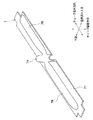
図2(a)は本第1実施形態におけるインサート7を示す平面図で、図2(b)は図2(a)の正面図である。図2(a)、(b)に示すように、インサート7は、チューブ2の扁平面と略平行な面を有してチューブ2の長手方向と略平行に延びるベース部71と、ベース部71の空気流れ方向両端部からベース部71に対して略直交する方向(チューブ積層方向)に突出してチューブ長手方向と略平行に延びる一対の側面リブ72とを有している。
Fig.2 (a) is a top view which shows the
インサート7の一対の側面リブ72には、側面リブ72におけるチューブ積層方向外側の端部からチューブ積層方向内側に向かって切り込まれた切り込み部73a、73bがそれぞれ形成されている。また、空気流れ上流側の側面リブ72に形成された切り込み部(以下、上流側切り込み部73aという)と、空気流れ下流側の側面リブ72に形成された切り込み部(以下、下流側切り込み部73bという)は、空気流れ方向において互いに重ならないように配置されている。
The pair of
インサート7のベース部71には、ベース部側膨出部74が形成されている。ベース部側膨出部74は、ベース部71の断面を略U字状にチューブ積層方向外側に膨らませることにより形成されている。また、ベース部側膨出部74は、インサート長手方向に生じる引っ張りまたは圧縮応力を、自身が変形することにより吸収するように構成されている。
A base portion
図2(a)に示すように、ベース部側膨出部74は、上流側切り込み部73aと下流側切り込み部73bとを連結するように形成されており、空気流れ方向に対して傾斜して配置されている。
As shown in FIG. 2 (a), the base portion
以上説明したように、インサート7のベース部71に断面が略U字状に膨らんだベース部側膨出部74を形成することで、インサート長手方向に生じる応力を吸収することができる。
As described above, by forming the base portion side bulged
また、ベース部側膨出部74を空気流れ方向に対して傾斜して配置することで、インサート7における応力吸収部、すなわちチューブ2を押さえ込む力が弱い部位をチューブ長手方向において分散させることができる。これにより、チューブ2の内圧が高くなった際に、インサート7がベース部側膨出部74において局所的に変形することを防止できる。このため、チューブ2が膨らんで変形することを防止できるので、チューブ2の破損を防止できる。
Further, the base portion-
したがって、熱歪みを低減させるとともに、耐圧性能を確保することが可能となる。 Therefore, it is possible to reduce thermal distortion and to ensure pressure resistance performance.
(第2実施形態)
次に、本発明の第2実施形態について図3に基づいて説明する。上記第1実施形態と同様の部分については同一の符号を付して説明を省略する。図3(a)は本第2実施形態におけるインサート7を示す平面図で、図3(b)は図3(a)の正面図である。
(Second Embodiment)
Next, a second embodiment of the present invention will be described with reference to FIG. The same parts as those in the first embodiment are denoted by the same reference numerals and description thereof is omitted. Fig.3 (a) is a top view which shows the
図3(a)、(b)に示すように、本実施形態のインサート7のベース部71には、スリット75が形成されている。本実施形態では、スリット75は、その長手方向がチューブ長手方向と略平行になるように配置されている。
As shown to Fig.3 (a), (b), the
また、ベース部側膨出部74は、空気流れ方向に2つに分割されている。ここで、分割された2つのベース部側膨出部74のうち、空気流れ上流側に配置されるものを第1のベース部側膨出部74aといい、空気流れ下流側に配置されるものを第2のベース部側膨出部74bという。
Moreover, the base part
2つのベース部側膨出部74a、74bは、スリット75を介して連結されている。また、2つのベース部側膨出部74a、74bは、同一直線状に配置されていない。本実施形態では、2つのベース部側膨出部74a、74bは、スリット75の長手方向両端部に1つずつ接続されている。
The two base portion
これにより、上記第1実施形態と同様の効果を得ることができる。 Thereby, the effect similar to the said 1st Embodiment can be acquired.
さらに、ベース部側膨出部74を空気流れ方向に2つに分割し、2つのベース部側膨出部74a、74bを、スリット75を介して連結することで、ベース部側膨出部74の長さをスリット75の空気流れ方向の長さ分短くすることができる。これにより、成形性を向上させることが可能となる。
Furthermore, the base part
また、2つのベース部側膨出部74a、74bを同一直線状に配置しないことで、ベース部側膨出部74の空気流れ方向に対する角度を変えずに、上流側切り込み部73aと空気流れ下流側の切り込み部73bとの距離を大きくすることができる。このため、ベース部側膨出部74の成形性を低下させずに、耐圧性能を確実に確保することが可能となる。
Further, by not arranging the two base portion side bulged
(第3実施形態)
次に、本発明の第3実施形態について図3に基づいて説明する。上記第2実施形態と同様の部分については同一の符号を付して説明を省略する。図4(a)は本第3実施形態におけるインサート7を示す平面図で、図4(b)は図4(a)の正面図である。
(Third embodiment)
Next, a third embodiment of the present invention will be described with reference to FIG. The same parts as those in the second embodiment are denoted by the same reference numerals and description thereof is omitted. Fig.4 (a) is a top view which shows the
図4に示すように、本実施形態の2つのベース部側膨出部74a、74bは、空気流れ方向に対してそれぞれ反対方向に傾斜している。
As shown in FIG. 4, the two base portion-
より詳細には、スリット75の第1のベース部側膨出部74aが接続される端部は、チューブ長手方向において上流側切り込み部73aより下流側切り込み部73b側に配置されている。一方、スリット75の第2のベース部側膨出部74bが接続される端部は、チューブ長手方向において下流側切り込み部73bより上流側切り込み部73aと反対側に配置されている。
More specifically, an end portion of the
これにより、上記第2実施形態と同様の効果を得ることができる。 Thereby, the effect similar to the said 2nd Embodiment can be acquired.
さらに、2つのベース部側膨出部74a、74bを、空気流れ方向に対してそれぞれ反対方向に傾斜させることで、ベース部側膨出部74a、74bを成形する際のスプリングバックを低減させることができるため、成形性を向上させることが可能となる。
Furthermore, the spring back at the time of shaping | molding the base part
(第4実施形態)
次に、本発明の第4実施形態について図3に基づいて説明する。上記第2実施形態と同様の部分については同一の符号を付して説明を省略する。図5(a)は本第4実施形態におけるインサート7を示す平面図で、図5(b)は図5(a)の正面図である。
(Fourth embodiment)
Next, a fourth embodiment of the present invention will be described with reference to FIG. The same parts as those in the second embodiment are denoted by the same reference numerals and description thereof is omitted. Fig.5 (a) is a top view which shows the
図5(a)、(b)に示すように、本実施形態のインサート7のベース部71には、2つのスリット75が形成されている。本実施形態では、2つのスリット75は、その長手方向がチューブ長手方向と略平行になるようにそれぞれ配置されている。ここで、2つのスリット75のうち、空気流れ上流側に配置されるものを第1のスリット75aといい、空気流れ下流側に配置されるものを第2のスリット75bという。
As shown in FIGS. 5A and 5B, two
また、ベース部側膨出部74は、空気流れ方向に3つに分割されている。3つのベース部側膨出部74a〜74cは、空気流れ方向に対して略平行に形成されるとともに、空気流れ方向においてそれぞれ重ならないように配設されている。ここで、分割された3つのベース部側膨出部74のうち、空気流れ上流側に配置されるものを第1のベース部側膨出部74aといい、空気流れ下流側に配置されるものを第2のベース部側膨出部74bといい、第1のベース部側膨出部74aと第2のベース部側膨出部74cとの間に配置されるものを第3のベース部側膨出部74cという。
Moreover, the base part
図5(a)に示すように、3つのベース部側膨出部74a〜74cは、2つスリット75a、75bを介して連結されている。より詳細には、第1のスリット75aのチューブ長手方向における一方の端部に第1のベース部側膨出部74aが接続され、他方の端部に第3のベース部側膨出部74cが接続されている。第3のベース部側膨出部74cの空気流れ下流側の端部には、第2のスリット75bのチューブ長手方向における一方の端部が接続され、他方の端部に第2のベース部側膨出部74bが接続されている。
As shown to Fig.5 (a), the three base part
これにより、上記第2実施形態と同様の効果を得ることができる。 Thereby, the effect similar to the said 2nd Embodiment can be acquired.
さらに、3つのベース部側膨出部74a〜74cを空気流れ方向に対して略平行に形成されるとともに、空気流れ方向においてそれぞれ重ならないように配設することで、ベース部側膨出部74を空気流れ方向に対して傾斜させる必要がないため、成形性を向上させることが可能となる。
Furthermore, while being substantially formed parallel to the three base portion-
(第5実施形態)
次に、本発明の第5実施形態について図6に基づいて説明する。上記第1実施形態と同様の部分については同一の符号を付して説明を省略する。図6(a)は本第5実施形態におけるインサート7を示す平面図で、図6(b)は図6(a)の正面図である。
(Fifth embodiment)
Next, a fifth embodiment of the present invention will be described with reference to FIG. The same parts as those in the first embodiment are denoted by the same reference numerals and description thereof is omitted. FIG. 6 (a) is a plan view showing the
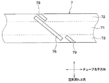
図6(a)、(b)に示すように、本実施形態のインサート7には、切り欠き部76が形成されている。切り欠き部76は、ベース部71を、空気流れ方向に対して傾斜するように空気流れ方向一端側から他端側に向かって切り欠くことによって形成されている。このため、切り欠き部76における空気流れ上流側の端部と空気流れ下流側の端部とが、空気流れ方向において互いに重なり合わないようになっている。
As shown in FIGS. 6 (a) and 6 (b), the
本実施形態では、切り欠き部76は、ベース部71の空気流れ上流側の端部から空気流れ下流側の端部まで連続的に形成されている。また、切り欠き部76は、側面リブ72にも連続的に形成されている。より詳細には、側面リブ72における切り欠き部76の端部と隣接する部位は、チューブ積層方向と略平行に切り欠かれている。したがって、本実施形態では、インサート7は、切り欠き部76によって完全に分断されている。
In the present embodiment, the
以上説明したように、インサート7のベース部71に切り欠き部76を形成することで、インサート長手方向に生じる応力を吸収することができる。
As described above, by forming the
また、切り欠き部76を空気流れ方向に対して傾斜して配置することで、インサート7における応力吸収部、すなわちチューブ2を押さえ込む力が弱い部位をチューブ長手方向において分散させることができる。これにより、チューブ2の内圧が高くなった際に、チューブ2が局所的に膨らむように変形することを防止できるため、チューブ2の破損を防止できる。
Further, by arranging the
したがって、熱歪みを低減させるとともに、耐圧性能を確保することが可能となる。 Therefore, it is possible to reduce thermal distortion and to ensure pressure resistance performance.
さらに、インサート7に切り欠き部76を形成するだけでインサート長手方向に生じる応力を吸収することができるため、簡易な構成で耐圧性能を確保することが可能となる。
Further, since the stress generated in the longitudinal direction of the insert can be absorbed simply by forming the
(第6実施形態)
次に、本発明の第6実施形態について図7に基づいて説明する。上記第5実施形態と同様の部分については同一の符号を付して説明を省略する。図7(a)は本第6実施形態におけるインサート7を示す平面図で、図7(b)は図7(a)の正面図である。
(Sixth embodiment)
Next, a sixth embodiment of the present invention will be described with reference to FIG. The same parts as those in the fifth embodiment are denoted by the same reference numerals and description thereof is omitted. Fig.7 (a) is a top view which shows the
図7(a)、(b)に示すように、本実施形態の切り欠き部76は、空気流れ方向における一端側(本実施形態では、空気流れ上流側の端部)のみが開放されている。より詳細には、切り欠き部76は、空気流れ方向における一端側がベース部71の空気流れ方向の端部に接続され、他端側(本実施形態では、空気流れ下流側の端部)がベース部71内に配置されている。すなわち、本実施形態では、インサート7は、切り欠き部76によって完全に分断されていない。
As shown in FIGS. 7A and 7B, the
このように、切り込み部76の一端側のみを開放することで、一方の側面リブ72を残して、剛性を必要以上に下げることを避けることができる。これにより、チューブ2を押さえ込む力をより大きくすることができるため、熱歪みを低減させるとともに、耐圧性能を確実に確保することが可能となる。
In this way, by opening only one end side of the
(第7実施形態)
次に、本発明の第7実施形態について図8に基づいて説明する。上記第6実施形態と同様の部分については同一の符号を付して説明を省略する。図8(a)は本第7実施形態におけるインサート7を示す平面図で、図8(b)は図8(a)の正面図である。
(Seventh embodiment)
Next, a seventh embodiment of the present invention will be described with reference to FIG. The same parts as those in the sixth embodiment are denoted by the same reference numerals and description thereof is omitted. Fig.8 (a) is a top view which shows the
図8(a)、(b)に示すように、本実施形態のインサート7のベース部71には、切り欠き部76が平行に3つ形成されている。3つの切り欠き部76は、全てベース部71を空気流れ上流側の端部から空気流れ下流側に向かって切り欠くことにより形成されている。
As shown in FIGS. 8A and 8B, the
このように、ベース部71に切り欠き部76を3つ形成することで、インサート長手方向に生じる応力を確実に吸収することができる。したがって、熱歪みをより低減させるとともに、耐圧性能を確保することが可能となる。
Thus, by forming the three
(第8実施形態)
次に、本発明の第8実施形態について図9に基づいて説明する。上記第7実施形態と同様の部分については同一の符号を付して説明を省略する。図9(a)は本第8実施形態におけるインサート7を示す平面図で、図9(b)は図9(a)の正面図である。
(Eighth embodiment)
Next, an eighth embodiment of the present invention will be described with reference to FIG. The same parts as those in the seventh embodiment are denoted by the same reference numerals and description thereof is omitted. FIG. 9A is a plan view showing the
図9(a)、(b)に示すように、インサート7のベース部71には、切り欠き部76が平行に3つ形成されている。本実施形態では、3つの切り欠き部76のうちチューブ長手方向外側に配置される切り欠き部76aは、ベース部71を空気流れ上流側の端部から空気流れ下流側に向かって切り欠くことにより形成されている。一方、3つの切り欠き部76のうちチューブ積層方向内側に配置される切り欠き部76bは、ベース部71を空気流れ下流側の端部から空気流れ上流側に向かって切り欠くことにより形成されている。
As shown in FIGS. 9A and 9B, the
これにより、上記第7実施形態と同様の効果を得ることができる。 Thereby, the same effect as that of the seventh embodiment can be obtained.
(第9実施形態)
次に、本発明の第9実施形態について図10に基づいて説明する。上記第7実施形態と同様の部分については同一の符号を付して説明を省略する。図10(a)は本第9実施形態におけるインサート7を示す平面図で、図10(b)は図10(a)の正面図である。
(Ninth embodiment)
Next, a ninth embodiment of the present invention will be described with reference to FIG. The same parts as those in the seventh embodiment are denoted by the same reference numerals and description thereof is omitted. FIG. 10 (a) is a plan view showing the
図10(a)、(b)に示すように、本実施形態のインサート7のベース部71には、切り欠き部76が4つ形成されている。4つの切り欠き部76のうち2つの切り欠き部(以下、第1の切り欠き部76cという)は、ベース部71の空気流れ上流側から下流側に向かって切り欠かれている。一方、4つの切り欠き部76のうち第1の切り欠き部76cを除く2つの切り欠き部(以下、第2の切り欠き部76dという)は、ベース部71の空気流れ下流側から上流側に向かって切り欠かれている。
As shown in FIGS. 10A and 10B, four
2つの第1の切り欠き部76cは、互いに略平行に配置されている。第2の切り欠き部76dは、空気流れ方向に対して第1の切り欠き部76cと反対方向に傾斜している。また、2つの第2の切り欠き部76dは、互いに略平行に配置されている。
The two
これにより、上記第7実施形態と同様の効果を得ることができる。 Thereby, the same effect as that of the seventh embodiment can be obtained.
(第10実施形態)
次に、本発明の第10実施形態について図11に基づいて説明する。上記第5実施形態と同様の部分については同一の符号を付して説明を省略する。図11(a)は本第10実施形態におけるインサート7を示す平面図で、図11(b)は図11(a)の正面図である。また、図12は、本第10実施形態におけるインサート7を示す斜視図である。
(10th Embodiment)
Next, a tenth embodiment of the present invention will be described with reference to FIG. The same parts as those in the fifth embodiment are denoted by the same reference numerals and description thereof is omitted. Fig.11 (a) is a top view which shows the
図11(a)、(b)および図12に示すように、本実施形態の切り欠き部76における空気流れ方向両端部は、切り欠き部76における他の部位より大きな略長方形形状(以下、長方形部760という)になっている。また、側面リブ72における長方形部760と隣接する部位には、側面リブ72の断面が略U字状に膨らんだ側面リブ側膨出部77が形成されている。本実施形態では、側面リブ側膨出部77は、インサート7の空気流れ方向内側に向かって膨出している。
As shown in FIGS. 11A, 11 </ b> B, and 12, the air flow direction both ends of the
以上説明したように、ベース部71に切り欠き部76を形成するとともに、一対の側面リブ72に側面リブ側膨出部77をそれぞれ形成することで、インサート長手方向に生じる応力を確実に吸収することができる。
As described above, by forming the
また、切り欠き部76を空気流れ方向に対して傾斜して配置することで、インサート7における応力吸収部、すなわちチューブ2を押さえ込む力が弱い部位をチューブ長手方向において分散させることができる。これにより、チューブ2の内圧が高くなった際に、チューブ2が局所的に膨らむように変形することを防止できるため、チューブ2の破損を防止できる。
Further, by arranging the
したがって、熱歪みを確実に低減させるとともに、耐圧性能を確保することが可能となる。 Therefore, it is possible to reliably reduce thermal distortion and to ensure pressure resistance performance.
(第11実施形態)
次に、本発明の第11実施形態について図13および図14に基づいて説明する。上記第1実施形態と同様の部分については同一の符号を付して説明を省略する。
(Eleventh embodiment)
Next, an eleventh embodiment of the present invention will be described with reference to FIGS. The same parts as those in the first embodiment are denoted by the same reference numerals and description thereof is omitted.
図13は本第11実施形態のインサート7を示す斜視図で、図14(a)は図13のA矢視図、図14(b)は図13のB−B断面図、図14(c)は図13のC−C断面図である。
FIG. 13 is a perspective view showing the
図13および図14(a)〜(c)に示すように、インサート7のベース部71には、チューブ積層方向外側に突出してインサート長手方向と略平行に延びるベース部側リブ(突起部)78が設けられている。ベース部側リブ78は、一端側がベース部側膨出部74に接続されている。本実施形態では、ベース部側リブ78の他端側は、ベース部71長手方向端部側に配置されている。
As shown in FIGS. 13 and 14A to 14C, the
ベース部側リブ78は、ベース部側膨出部74を挟んで1つずつ設けられている、すなわちベース部71におけるベース部側膨出部74の両側に1つずつ設けられている。2つのベース部側リブ78は、ベース部71の空気流れ方向の中心をインサート長手方向に横切る中心線(以下、単に中心線という)Lの一側と他側とにそれぞれ配置されている。本実施形態では、2つのベース部側リブ78は、ベース部側膨出部74の空気流れ方向の一端と他端に、それぞれ接続されている。
The base
また、図14(b)、(c)に示すように、ベース部側リブ78は、断面略半円状に形成されている。
Further, as shown in FIGS. 14B and 14C, the base
ところで、加圧時(チューブ2の内圧が高くなった時)には、ラジエータ1全体にチューブ積層方向に膨らむような変形が生じ、車両の振動等による加振時には、ラジエータ1全体にチューブ長手方向とチューブ積層方向の変形が生じる。これに対し、インサート7のベース部71に断面が略U字状に膨らんだベース部側膨出部74を形成することで、インサート長手方向に生じる応力を吸収することができる。さらに、本実施形態のように、インサート7のベース部71にチューブ積層方向外側に突出するベース部側リブ78を設けることで、インサート7のチューブ積層方向の剛性を高くすることができる。これにより、耐圧性能および耐振性能を向上させることが可能となる。
By the way, when pressurizing (when the internal pressure of the
ところで、インサート7の長手方向に応力が発生した際に、インサート7のベース部71とベース部側膨出部74との接続部に応力が集中し、接続部が破断する可能性がある。これに対し、ベース部側リブ78の一端側とベース部側膨出部74とを接続することで、ベース部71とベース部側膨出部74との接続部に応力が集中することを防止できる。
By the way, when stress is generated in the longitudinal direction of the
また、ベース部側リブ78によりインサート7のチューブ積層方向の剛性を確保することができるため、側面リブ72の高さ(チューブ積層方向の長さ)を低くすることができる。したがって、ラジエータ1の搭載スペースに制限がある場合でも、側面リブ72の高さを低くした分、コア部4を大きくすることができるため、熱交換性能を向上させることが可能となる。
Moreover, since the rigidity of the
また、ベース部側リブ78を、ベース部側膨出部74を挟んで1つずつ設けることで、インサート7の長手方向の広い範囲にベース部側リブ78を配置することができるので、インサート7のチューブ積層方向の剛性をより高くすることができる。これにより、耐圧性能および耐震性能をより向上させることが可能となる。
Moreover, since the base
さらに、ベース部側リブ78を、ベース部71における中心線Lの一側と他側とにそれぞれ配置することで、インサート7の空気流れ方向の広い範囲にベース部側リブ78を設けることができるので、インサート7のチューブ積層方向の剛性をさらに高くすることができる。これにより、耐圧性能および耐震性能をさらに向上させることが可能となる。
Furthermore, the base
(第12実施形態)
次に、本発明の第12実施形態について図15および図16に基づいて説明する。本第12実施形態は、上記第11実施形態と比較して、側面リブ72を廃止した点が異なるものである。上記第11実施形態と同様の部分については同一の符号を付して説明を省略する。
(Twelfth embodiment)
Next, a twelfth embodiment of the present invention will be described with reference to FIGS. The twelfth embodiment differs from the eleventh embodiment in that the
図15は本第12実施形態のインサート7を示す斜視図で、図16(a)は図15のD矢視図、図16(b)は図15のE−E断面図、図16(c)は図15のF−F断面図である。図15および図16(a)〜(c)に示すように、インサート7は、ベース部71のみを有している。
FIG. 15 is a perspective view showing the
このように、インサート7のベース部71にチューブ積層方向外側に突出するベース部側リブ78を設けることで、インサート7のチューブ積層方向の剛性を高くすることができるため、側面リブを廃止することができる。したがって、ラジエータ1の搭載スペースに制限がある場合でも、側面リブを廃止した分、コア部4を大きくすることができるため、熱交換性能を向上させることが可能となる。
As described above, since the
(第13実施形態)
次に、本発明の第13実施形態について図17に基づいて説明する。本第13実施形態は、上記第12実施形態と比較して、ベース部側リブ78の配置が異なるものである。上記第12実施形態と同様の部分については同一の符号を付して説明を省略する。
(13th Embodiment)
Next, a thirteenth embodiment of the present invention will be described with reference to FIG. The thirteenth embodiment differs from the twelfth embodiment in the arrangement of the base
図17は、本第13実施形態のインサート7を示す斜視図である。図17に示すように、ベース部71におけるベース部側膨出部74の両側に設けられた2つのベース部側リブ78は、ベース部側膨出部74における空気流れ方向の中央部近傍にそれぞれ接続されている。これにより、上記第12実施形態と同様の効果を得ることができる。
FIG. 17 is a perspective view showing the
(第14実施形態)
次に、本発明の第14実施形態について図18に基づいて説明する。本第14実施形態は、上記第11実施形態と比較して、ベース部側リブ78の配置が異なるものである。上記第11実施形態と同様の部分については同一の符号を付して説明を省略する。
(14th Embodiment)
Next, a fourteenth embodiment of the present invention will be described with reference to FIG. In the fourteenth embodiment, the arrangement of the base
図18は、本第14実施形態のインサート7を示す斜視図である。図18に示すように、ベース部71におけるベース部側膨出部74の両側に設けられた2つのベース部側リブ78は、ベース部71における中心線L上にそれぞれ配置されている。また、2つのベース部側リブ78は、ベース部側膨出部74における空気流れ方向の中央部にそれぞれ接続されている。これにより、上記第11実施形態と同様の効果を得ることができる。
FIG. 18 is a perspective view showing the
(第15実施形態)
次に、本発明の第15実施形態について図19に基づいて説明する。本第15実施形態は、上記第12実施形態と比較して、第2のベース部側リブ78aを設けた点が異なるものである。上記第12実施形態と同様の部分については同一の符号を付して説明を省略する。
(Fifteenth embodiment)
Next, a fifteenth embodiment of the present invention is described with reference to FIG. The fifteenth embodiment is different from the twelfth embodiment in that a second base
図19は、本第15実施形態のインサート7を示す斜視図である。図19に示すように、ベース部71におけるベース部側リブ78が設けられていない部位には、チューブ積層方向外側に突出してインサート長手方向と略平行に延びる第2のベース部側リブ78aが設けられている。本実施形態では、第2のベース部側リブ78aは、断面略半円状に形成されている。
FIG. 19 is a perspective view showing the
また、第2のベース部側リブ78aは、ベース部側膨出部74を挟んで1つずつ設けられている。2つの第2のベース部側リブ78aは、ベース部71の中心線Lの一側と他側とにそれぞれ配置されている。また、ベース部71の中心線Lの一側および他側のそれぞれにおいて、第2のベース部側リブ78aは、ベース部側膨出部74に対してベース部側リブ78と反対側に配置されている。
The second base
以上説明したように、ベース部71におけるベース部側リブ78が設けられていない部位に第2のベース部側リブ78aを設けることで、インサート7のチューブ積層方向の剛性をより高くすることができる。これにより、耐圧性能および耐震性能をより向上させることが可能となる。
As described above, the rigidity of the
また、第2のベース部側リブ78aを、ベース部側膨出部74の両側に1つずつ設けることで、インサート7の長手方向における広い範囲に第2のベース部側リブ78aを配置することができる。さらに、2つの第2のベース部側リブ78aを、ベース部71の中心線Lの一側と他側とにそれぞれ配置することで、インサート7の空気流れ方向における広い範囲に第2のベース部側リブ78を設けることができる。さらに、ベース部71の中心線Lの一側および他側のそれぞれにおいて、第2のベース部側リブ78aを、ベース部側膨出部74に対してベース部側リブ78と反対側に配置することで、ベース部71のほぼ全域にベース部側リブ78もしくは第2のベース部側リブ78aを設けることができる。これらにより、インサート7のチューブ積層方向の剛性をさらに高くすることができ、耐圧性能および耐震性能をさらに向上させることが可能となる。
Further, by providing one second base
(第16実施形態)
次に、本発明の第16実施形態について図20に基づいて説明する。本第16実施形態は、上記第15実施形態と比較して、第2のベース部側リブ78aの一端側をベース部側膨出部74に接続した点が異なるものである。上記第15実施形態と同様の部分については同一の符号を付して説明を省略する。
(Sixteenth embodiment)
Next, a sixteenth embodiment of the present invention will be described with reference to FIG. The sixteenth embodiment is different from the fifteenth embodiment in that one end side of the second base
図20は、本第16実施形態のインサート7を示す斜視図である。図20に示すように、第2のベース部側リブ78aは、一端側がベース部側膨出部74に接続されている。本実施形態では、中心線Lの一側および他側のそれぞれにおいて、ベース部側リブ78と第2のベース部側リブ78aは、同一直線上に配置されている。また、2つの第2のベース部側リブ78aは、ベース部側膨出部74の空気流れ方向の一端と他端に、それぞれ接続されている。
FIG. 20 is a perspective view showing the
以上説明したように、第2のベース部側リブ78aの一端側をベース部側膨出部74に接続することで、ベース部71とベース部側膨出部74との接続部に応力が集中することをより確実に防止できる。
As described above, by concentrating one end side of the second base
(第17実施形態)
次に、本発明の第17実施形態について図21に基づいて説明する。上記第16実施形態と同様の部分については同一の符号を付して説明を省略する。
(17th Embodiment)
Next, a seventeenth embodiment of the present invention will be described with reference to FIG. The same parts as those in the sixteenth embodiment are denoted by the same reference numerals and description thereof is omitted.
図21は、本第17実施形態のインサート7を示す斜視図である。図21に示すように、ベース部側リブ78および第2のベース部側リブ78aは、ベース部側膨出部74の空気流れ方向の両端部以外の部位に、それぞれ接続されている。
FIG. 21 is a perspective view showing the
より詳細には、ベース部71における中心線Lより空気流れ上流側に配置されたベース部側リブ78および第2のベース部側リブ78aは、ベース部側膨出部74における中心線Lより空気流れ上流側の部位に接続されている。また、ベース部71における中心線Lより空気流れ下流側に配置されたベース部側リブ78および第2のベース部側リブ78aは、ベース部側膨出部74における中心線Lより空気流れ下流側の部位に接続されている。これにより、上記第16実施形態と同様の効果を得ることができる。
More specifically, the base
(第18実施形態)
次に、本発明の第18実施形態について図22に基づいて説明する。本第18実施形態は、上記第14実施形態と比較して、第2のベース部側リブ78aを設けた点が異なるものである。上記第14実施形態と同様の部分については同一の符号を付して説明を省略する。
(Eighteenth embodiment)
Next, an eighteenth embodiment of the present invention will be described with reference to FIG. The eighteenth embodiment is different from the fourteenth embodiment in that a second base
図22は、本第18実施形態におけるインサート7を示す平面図である。図22に示すように、ベース部71におけるベース部側リブ78が設けられていない部位には、チューブ積層方向外側に突出してインサート長手方向と略平行に延びる第2のベース部側リブ78aが設けられている。第2のベース部側リブ78aは、ベース部側膨出部74を挟んで1つずつ設けられている。2つの第2のベース部側リブ78aは、ベース部71の中心線Lの一側と他側とにそれぞれ配置されている。
FIG. 22 is a plan view showing the
本実施形態では、2つの第2のベース部側リブ78aは、2つのベース部側リブ78の他端側(ベース部膨出部74に接続されていない側)にそれぞれ接続されている。より詳細には、ベース部71における中心線Lより空気流れ上流側に配置された第2のベース部側リブ78aは、ベース部側リブ78の空気流れ上流側の面に接続されている。また、ベース部71における中心線Lより空気流れ下流側に配置された第2のベース部側リブ78aは、ベース部側リブ78の空気流れ下流側の面に接続されている。
In the present embodiment, the two second base
以上説明したように、ベース部71におけるベース部側リブ78が設けられていない部位に第2のベース部側リブ78aを設けることで、インサート7のチューブ積層方向の剛性をより高くすることが可能となる。これにより、耐圧性能および耐震性能をより向上させることが可能となる。
As described above, the rigidity of the
(第19実施形態)
次に、本発明の第19実施形態について図23および図24に基づいて説明する。上記第5実施形態と同様の部分については同一の符号を付して説明を省略する。
(Nineteenth embodiment)
Next, a nineteenth embodiment of the present invention will be described with reference to FIGS. The same parts as those in the fifth embodiment are denoted by the same reference numerals and description thereof is omitted.
図23は、本第19実施形態におけるインサート7を示す斜視図である。図23に示すように、インサート7のベース部71には、第1の切り欠き部76が、空気流れ方向に対して傾斜するように空気流れ方向一端側から他端側に向かって切り欠くことによって形成されている。第1の切り欠き部76は、側面リブ72にも連続的に形成されている。すなわち、第1の切り欠き部76のうちベース部71に形成された部分の空気流れ方向に対する傾斜角度θ1が、第1の切り欠き部76のうち側面リブ72に形成された部分のチューブ積層方向に対する傾斜角度θ2と等しくなっている。また、第1の切り欠き部76の両端部は、一対の側面リブ72の面内にそれぞれ配置されており、このため側面リブ72は完全には分断されていない。
FIG. 23 is a perspective view showing the
一対の側面リブ72には、チューブ積層方向外側の端部から内側に向かって切り欠かれた第2の切り欠き部79がそれぞれ形成されている。第2の切り欠き部79は、一端側のみが開放されており、本実施形態では、第2の切り欠き部79の他端(開放されていない側の端部)は、側面リブ72の面内に配置されている。また、第2の切り欠き部79は、第1の切り欠き部76と略平行に形成されている。
The pair of
本実施形態では、インサート長手方向において、空気流れ下流側の側面リブ72に形成された第2の切り欠き部79(以下、下流側第2の切り欠き部79bという)は、第1の切り欠き部76から見て、空気流れ上流側の側面リブ72に形成された第2の切り欠き部79(以下、上流側第2の切り欠き部79aという)と同じ側に設けられている。すなわち、インサート長手方向において、下流側第2の切り欠き部79bは、第1の切り欠き部76に対して、上流側第2の切り欠き部79aが配置された方と同じ側に配置されている。
In the present embodiment, in the longitudinal direction of the insert, the
図24は、本第19実施形態における側面リブ72を折り曲げる前のインサート7を示す概略平面図である。図24に示すように、本実施形態では、インサート5のプレス成形と同時に第1、第2の切り欠き部76、79を成形している。そして、第1、第2の切り欠き部76、79が成形されたインサート7の短手方向両端部を同じ向きに折り曲げることにより側面リブ72を成形し、これにより図23に示されるインサート7が完成する。
FIG. 24 is a schematic plan view showing the
以上説明したように、第1の切り欠き部76を側面リブ72まで延長するとともに、第1の切り欠き部76の両端部を、一対の側面リブ72の面内にそれぞれ配置することで、側面リブ72が完全には切断されていないため、インサート7の剛性を必要以上に下げることを避けることができる。これにより、耐圧性能および耐震性能を確実に確保することが可能となる。
As described above, the
ところで、第1の切り欠き部76の両端部が一対の側面リブ72の面内にそれぞれ配置されているため、インサート長手方向に生じる応力を吸収し難くなる。そこで、インサート7に、側面リブ72のチューブ積層方向外側の端部から第1の切り欠き部76と略平行に切り欠かれた第2の切り欠き部79を設定することで、インサート長手方向に生じる応力を吸収しやすくすることができる。これにより、熱歪みをより低減させることが可能となる。
By the way, since the both ends of the
さらに、インサート7をプレス成形する際に、予め第1、第2の切り欠き部76、79を成形しておけばよいので、インサート7をチューブ2およびフィン3とともにろう付けしてコア部4を成形した後にインサート7を切断して切り欠き部を成形する工程が不要となる。このため、成形性を向上させることが可能となる。
Further, when the
(第20実施形態)
次に、本発明の第20実施形態について図25に基づいて説明する。本第20実施形態は、上記第19実施形態と比較して、インサート7における第2の切り欠き部79の他端が配置されている部位が異なるものである。上記第19実施形態と同様の部分については同一の符号を付して説明を省略する。
(20th embodiment)
Next, a twentieth embodiment of the present invention will be described with reference to FIG. 20th Embodiment differs in the site | part by which the other end of the
図25は、本第20実施形態におけるインサート7を示す斜視図である。図25に示すように、第2の切り欠き部79の他端(開放されていない側の端部)は、インサート7のベース部71の面内に配置されている。これにより、上記第19実施形態と同様の効果を得ることができる。
FIG. 25 is a perspective view showing the
(第21実施形態)
次に、本発明の第21実施形態について図26に基づいて説明する。本第21実施形態は、上記第20実施形態と比較して、第2の切り欠き部79の配置が異なるものである。上記第20実施形態と同様の部分については同一の符号を付して説明を省略する。
(21st Embodiment)
Next, a twenty-first embodiment of the present invention will be described with reference to FIG. The twenty-first embodiment differs from the twentieth embodiment in the arrangement of the
図26は、本第21実施形態におけるインサート7を示す斜視図である。図26に示すように、インサート長手方向において、下流側第2の切り欠き部79bは、第1の切り欠き部76から見て、上流側第2の切り欠き部79aと反対側に設けられている。すなわち、インサート長手方向において、下流側第2の切り欠き部79bは、第1の切り欠き部76に対して、上流側第2の切り欠き部79aが配置された方と反対側に配置されている。これにより、上記第20実施形態と同様の効果を得ることができる。
FIG. 26 is a perspective view showing the
(第22実施形態)
次に、本発明の第22実施形態について図27に基づいて説明する。本第22実施形態は、上記第21実施形態と比較して、第3の切り欠き部80を設けた点が異なるものである。上記第21実施形態と同様の部分については同一の符号を付して説明を省略する。
(Twenty-second embodiment)
Next, a twenty-second embodiment of the present invention is described with reference to FIG. The twenty-second embodiment differs from the twenty-first embodiment in that a
図27は、本第22実施形態におけるインサート7を示す斜視図である。図27に示すように、一対の側面リブ72には、チューブ積層方向外側の端部から内側に向かって切り欠かれた第3の切り欠き部80がそれぞれ形成されている。第3の切り欠き部80は、一端側のみが開放されており、本実施形態では、第3の切り欠き部80の他端(開放されていない側の端部)は、側面リブ72の面内に配置されている。また、第3の切り欠き部80は、第1、第2の切り欠き部76、79と略平行に形成されている。
FIG. 27 is a perspective view showing the
本実施形態では、空気流れ上流側の側面リブ72に形成された第3の切り欠き部80(以下、上流側第3の切り欠き部80aという)は、上流側第2の切り欠き部79aに対して第1の切り欠き部76と反対側に配置されている。また、空気流れ下流側の側面リブ72に形成された第3の切り欠き部80(以下、下流側第3の切り欠き部80bという)は、第1の切り欠き部76に対して下流側第2の切り欠き部79bと反対側に配置されている。なお、第3の切り欠き部80も、インサート5のプレス成形と同時に成形される。
In the present embodiment, the third notch 80 (hereinafter referred to as the upstream
以上説明したように、インサート7に、側面リブ72のチューブ積層方向外側の端部から第1の切り欠き部76と略平行に切り欠かれた第2、第3の切り欠き部79、80を設定することで、インサート長手方向に生じる応力をさらに吸収しやすくすることができる。これにより、熱歪みをさらに低減させることが可能となる。
As described above, the
(他の実施形態)
なお、上記各実施形態では、冷却水が水平方向に流れるクロスフロー型のラジエータ1に本発明を適用した実施形態について述べたが、冷却水が上下方向に流れるダウンフロー型のラジエータに本発明を適用することもできる。
(Other embodiments)
In each of the above embodiments, the embodiment in which the present invention is applied to the
また、上記各実施形態では、インサート7における応力吸収部がコア部4と非接触の状態となっている例について説明したが、これに限らず、インサート7における応力吸収部がコア部4と接触していてもよい。
Moreover, although each said embodiment demonstrated the example in which the stress absorption part in the
また、上記第7および第8実施形態では、ベース部71に切り込み部76を3つ形成したが、これに限らず、2つ、もしくは4つ以上形成してもよい。
Moreover, in the said 7th and 8th embodiment, although the three cut | notch
同様に、上記第9実施形態では、ベース部71に切り込み部76を4つ形成したが、これに限らず、2つまたは3つ、もしくは5つ以上形成してもよい。
Similarly, in the ninth embodiment, four cut
また、上記第11〜18実施形態では、ベース部側リブ78を断面略半円状に形成したが、これに限らず、断面三角形状、断面矩形状等、他の形状に形成してもよい。
Moreover, in the said 11th-18th embodiment, although the base
同様に、上記第15〜18実施形態では、第2のベース部側リブ78aを断面略半円状に形成したが、これに限らず、断面三角形状、断面矩形状等、他の形状に形成してもよい。
Similarly, in the fifteenth to eighteenth embodiments, the second base
2…チューブ、4…コア部、5…ヘッダタンク、7…インサート、71…ベース部、72…側面リブ、73a、73b…切り込み部、74…ベース部側膨出部(応力吸収部)、75…スリット、76…切り欠き部(応力吸収部)、77…側面リブ側膨出部(応力吸収部)、78…ベース部側リブ(突起部)、78a…第2のベース部側リブ、79…第2の切り欠き部。 2 ... Tube, 4 ... Core part, 5 ... Header tank, 7 ... Insert, 71 ... Base part, 72 ... Side rib, 73a, 73b ... Notch part, 74 ... Base part side bulging part (stress absorbing part), 75 ... Slit, 76 ... Notched portion (stress absorbing portion), 77 ... Side rib side bulged portion (stress absorbing portion), 78 ... Base portion side rib (projecting portion), 78a ... Second base portion side rib, 79 ... second notch.
Claims (25)
前記チューブ(2)の長手方向両端部にて前記チューブ(2)の長手方向と直交する方向に延びて前記チューブ(2)と連通するヘッダタンク(5)と、
前記コア部(4)の端部にて前記コア部(4)と接触するように前記チューブ(2)の長手方向と略平行に配置され、前記コア部(4)から熱が伝わるとともに、両端部が前記ヘッダタンク(5)に支持されたインサート(7)とを備える熱交換器であって、
前記チューブ(2)は、空気流れ方向に沿って扁平な断面形状を有しており、
前記チューブ(2)の両側の扁平面には波状に成形されたフィン(3)の頂部が接合されており、
前記インサート(7)は、前記コア部(4)の端部に位置する前記波状のフィン(3)の頂部と接触するようになっており、
前記インサート(7)には、前記インサート(7)の長手方向に生じる応力を吸収する応力吸収部(74、76、77)が形成されており、
前記応力吸収部(74、76、77)は、前記インサート(7)の空気流れ上流側から下流側に渡って空気流れ方向に対して傾斜して設けられており、
前記応力吸収部(74、76、77)における空気流れ最上流側の端部と空気流れ最下流側の端部とが、空気流れ方向において互いに重なり合わないように配置されていることを特徴とする熱交換器。 A core portion (4) having a plurality of tubes (2) through which a heat medium flows;
A header tank (5) extending in a direction perpendicular to the longitudinal direction of the tube (2) at both longitudinal ends of the tube (2) and communicating with the tube (2);
The core portion (4) is disposed substantially in parallel with the longitudinal direction of the tube (2) so as to come into contact with the core portion (4) at the end portion, and heat is transferred from the core portion (4), A heat exchanger comprising an insert (7) supported by the header tank (5),
The tube (2) has a flat cross-sectional shape along the air flow direction,
The flat portions on both sides of the tube (2) are joined to the tops of the corrugated fins (3),
The insert (7) comes into contact with the top of the wavy fin (3) located at the end of the core (4),
The insert (7) is formed with stress absorbing portions (74, 76, 77) that absorb stress generated in the longitudinal direction of the insert (7).
The stress absorbing portion (74, 76, 77) is provided to be inclined with respect to the air flow direction from the air flow upstream side to the downstream side of the insert (7),
An end on the most upstream side of the air flow and an end on the most downstream side of the air flow in the stress absorbing portion (74, 76, 77) are arranged so as not to overlap each other in the air flow direction. Heat exchanger.
前記チューブ(2)の長手方向両端部にて前記チューブ(2)の長手方向と直交する方向に延びて前記チューブ(2)と連通するヘッダタンク(5)と、
前記コア部(4)の端部にて前記コア部(4)と接触するように前記チューブ(2)の長手方向と略平行に配置され、前記コア部(4)から熱が伝わるとともに、両端部が前記ヘッダタンク(5)に支持されたインサート(7)とを備える熱交換器であって、
前記チューブ(2)は、空気流れ方向に沿って扁平な断面形状を有しており、
前記インサート(7)は、前記チューブ(2)の扁平面と略平行な面を有してチューブ(2)の長手方向と略平行に延びるベース部(71)と、前記ベース部(71)の空気流れ方向両端部から前記ベース部(71)に対して略直交する方向に突出して前記チューブ(2)の長手方向と略平行に延びる一対の側面リブ(72)とを有しており、
前記ベース部(71)には、前記ベース部(71)の断面が略U字状に膨らんだベース部側膨出部(74)が形成され、
前記ベース部側膨出部(74)は、前記インサート(7)の空気流れ上流側から下流側に渡って設けられており、
前記ベース部側膨出部(74)における空気流れ最上流側の端部と空気流れ最下流側の端部とが、空気流れ方向において互いに重なり合わないように配置されており、
前記インサート(7)の長手方向に生じる応力を吸収する応力吸収部が前記ベース部側膨出部(74)によって構成され、
前記側面リブ(72)における前記ベース部側膨出部(74)の前記最上流側端部と前記最下流側端部に対応する部位には、それぞれ切り込み部(73a、73b)が形成されていることを特徴とする熱交換器。 A core portion (4) having a plurality of tubes (2) through which a heat medium flows;
A header tank (5) extending in a direction perpendicular to the longitudinal direction of the tube (2) at both longitudinal ends of the tube (2) and communicating with the tube (2);
The core portion (4) is disposed substantially in parallel with the longitudinal direction of the tube (2) so as to come into contact with the core portion (4) at the end portion, and heat is transferred from the core portion (4), A heat exchanger comprising an insert (7) supported by the header tank (5),
The tube (2) has a flat cross-sectional shape along the air flow direction,
The insert (7) includes a base portion (71) having a surface substantially parallel to the flat surface of the tube (2) and extending substantially parallel to the longitudinal direction of the tube (2), and the base portion (71). A pair of side ribs (72) projecting from both ends of the air flow direction in a direction substantially orthogonal to the base portion (71) and extending substantially parallel to the longitudinal direction of the tube (2);
The base part (71) is formed with a base part side bulging part (74) in which a cross section of the base part (71) swells in a substantially U shape,
The base part side bulging part (74) is provided from the air flow upstream side to the downstream side of the insert (7),
The end on the most upstream side of the air flow and the end on the most downstream side of the air flow in the base side bulging portion (74) are arranged so as not to overlap each other in the air flow direction ,
A stress absorbing part that absorbs stress generated in the longitudinal direction of the insert (7 ) is constituted by the base part side bulging part (74),
Cut portions (73a, 73b) are formed in portions of the side ribs (72) corresponding to the most upstream end and the most downstream end of the base portion side bulging portion (74), respectively. heat exchanger, characterized in that there.
前記チューブ(2)の長手方向両端部にて前記チューブ(2)の長手方向と直交する方向に延びて前記チューブ(2)と連通するヘッダタンク(5)と、
前記コア部(4)の端部にて前記コア部(4)と接触するように前記チューブ(2)の長手方向と略平行に配置され、前記コア部(4)から熱が伝わるとともに、両端部が前記ヘッダタンク(5)に支持されたインサート(7)とを備える熱交換器であって、
前記チューブ(2)は、空気流れ方向に沿って扁平な断面形状を有しており、
前記インサート(7)は、前記チューブ(2)の扁平面と略平行な面を有して前記チューブ(2)の長手方向と略平行に延びるベース部(71)を有しており、
前記ベース部(71)には、前記ベース部(71)の断面が略U字状に膨らんだベース部側膨出部(74)が形成され、
前記ベース部側膨出部(74)は、前記インサート(7)の空気流れ上流側から下流側に渡って設けられており、
前記ベース部側膨出部(74)における空気流れ最上流側の端部と空気流れ最下流側の端部とが、空気流れ方向において互いに重なり合わないように配置されており、
前記インサート(7)の長手方向に生じる応力を吸収する応力吸収部が前記ベース部側膨出部(74)によって構成され、
前記ベース部(71)には、チューブ積層方向外側に突出して前記インサート(7)の長手方向と略平行に延びるベース部側リブ(78)が設けられており、
前記ベース部側リブ(78)は、一端側が前記ベース部側膨出部(74)に接続されていることを特徴とする熱交換器。 A core portion (4) having a plurality of tubes (2) through which a heat medium flows;
A header tank (5) extending in a direction perpendicular to the longitudinal direction of the tube (2) at both longitudinal ends of the tube (2) and communicating with the tube (2);
The core portion (4) is disposed substantially in parallel with the longitudinal direction of the tube (2) so as to come into contact with the core portion (4) at the end portion, and heat is transferred from the core portion (4), A heat exchanger comprising an insert (7) supported by the header tank (5),
The tube (2) has a flat cross-sectional shape along the air flow direction,
The insert (7) has a base portion (71) having a surface substantially parallel to the flat surface of the tube (2) and extending substantially parallel to the longitudinal direction of the tube (2),
The base part (71) is formed with a base part side bulging part (74) in which a cross section of the base part (71) swells in a substantially U shape,
The base part side bulging part (74) is provided from the air flow upstream side to the downstream side of the insert (7),
The end on the most upstream side of the air flow and the end on the most downstream side of the air flow in the base side bulging portion (74) are arranged so as not to overlap each other in the air flow direction ,
A stress absorbing part that absorbs stress generated in the longitudinal direction of the insert (7 ) is constituted by the base part side bulging part (74),
The base portion (71) is provided with a base portion side rib (78) that protrudes outward in the tube stacking direction and extends substantially parallel to the longitudinal direction of the insert (7).
One end side of the base part side rib (78) is connected to the base part side bulging part (74), The heat exchanger characterized by the above-mentioned.
前記インサート(7)は、前記コア部(4)の端部に位置する前記波状のフィン(3)の頂部と接触するようになっていることを特徴とする請求項2または3に記載の熱交換器。Heat according to claim 2 or 3, characterized in that the insert (7) is adapted to contact the top of the undulating fin (3) located at the end of the core (4). Exchanger.
前記複数のベース部側膨出部(74)は、前記ベース部(71)に形成されたスリット(75)を介して連結されていることを特徴とする請求項2ないし5のいずれか1つに記載の熱交換器。 The base portion side bulging portion (74) is divided into a plurality of air flow directions,
It said plurality of base portion-side expansion (74), any one of claims 2 to 5, characterized in that it is connected via a slit (75) formed in the base portion (71) The heat exchanger as described in.
前記応力吸収部は、前記ベース部(71)に空気流れ方向に対して傾斜するように切り欠かれた切り欠き部(76)であることを特徴とする請求項1に記載の熱交換器。 Before SL insert (7), the longitudinal and the base portion extending substantially parallel to the tube the tube has a substantially plane parallel to the flat surface of the (2) (2) and (71), said base portion (71) And a pair of side ribs (72) extending in a direction substantially orthogonal to the tube (2) and extending substantially parallel to the longitudinal direction of the tube (2),
2. The heat exchanger according to claim 1, wherein the stress absorbing portion is a notched portion (76) cut out in the base portion (71) so as to be inclined with respect to the air flow direction.
前記複数の切り欠き部(76)における開放された端部は、前記ベース部(71)における空気流れ上流側と下流側に互い違いに配置されていることを特徴とする請求項10に記載の熱交換器。 A plurality of the notches (76) are provided, and only one end side is opened,
11. The heat according to claim 10 , wherein the open ends of the plurality of notches are arranged alternately on the upstream side and the downstream side of the air flow in the base part. Exchanger.
前記応力吸収部は、前記側面リブ側膨出部(77)を含んでいることを特徴とする請求項10に記載の熱交換器。 The portion adjacent to the notch (76) in front Symbol pair of side ribs (72), said side ribs (72) cross-section side ribs side bulge bulging direction of air flow in a substantially U shape (77) is formed,
The heat exchanger according to claim 10 , wherein the stress absorbing part includes the side rib side bulging part (77).
前記突起部(78)は、前記応力吸収部(74、76、77)に接続されていることを特徴とする請求項1、10ないし15のいずれか1つに記載の熱交換器。 The insert (7) is provided with a protrusion (78) protruding outward in the tube stacking direction,
The protrusion (78) A heat exchanger according to any one of claims 1, 10 to 15, characterized in that it is connected to the stress absorbing portions (74, 76, 77).
前記側面リブ(72)における前記ベース部側膨出部(74)の前記最上流側端部と前記最下流側端部に対応する部位には、それぞれ切り込み部(73a、73b)が形成されていることを特徴とする請求項3に記載の熱交換器。 The insert (7) protrudes from both ends of the base portion (71) in the air flow direction in a direction substantially orthogonal to the base portion (71) and extends substantially parallel to the longitudinal direction of the tube (2). Side ribs (72),
Cut portions (73a, 73b) are formed in portions of the side ribs (72) corresponding to the most upstream end and the most downstream end of the base portion side bulging portion (74), respectively. The heat exchanger according to claim 3 , wherein
前記第2のベース部側リブ(78a)は、前記ベース部側膨出部(74)を挟んで1つずつ設けられているとともに、前記ベース部(71)の空気流れ方向の中心を前記インサート(7)の長手方向に横切る中心線(L)に対して空気流れ方向の一側と他側とにそれぞれ配置されており、
前記中心線(L)に対して空気流れ方向の一側および他側のそれぞれにおいて、前記第2のベース部側リブ(78a)は、前記ベース部側膨出部(74)に対して前記ベース部側リブ(78)と反対側に配置されていることを特徴とする請求項19に記載の熱交換器。 The base portion (71) is provided with a second base portion side rib (78a) protruding outward in the tube stacking direction and extending substantially parallel to the longitudinal direction of the insert (7).
The second base portion side ribs (78a) are provided one by one with the base portion side bulging portion (74) in between, and the center of the base portion (71) in the air flow direction is the insert. (7) are arranged on one side and the other side in the air flow direction with respect to the center line (L) crossing in the longitudinal direction,
The second base part side rib (78a) is located on the base part side bulged part (74) on the one side and the other side in the air flow direction with respect to the center line (L) . The heat exchanger according to claim 19 , wherein the heat exchanger is arranged on the side opposite to the part-side rib (78).
前記ベース部(71)には、前記チューブ積層方向外側に突出して前記インサート(7)の長手方向と略平行に延びる第2のベース部側リブ(78a)が設けられており、
前記第2のベース部側リブ(78a)は、前記ベース部側膨出部(74)を挟んで1つずつ設けられているとともに、前記ベース部側リブ(78)にそれぞれ接続されていることを特徴とする請求項3または17に記載の熱交換器。 The base portion side ribs (78) are provided one by one with the base portion side bulging portion (74) interposed therebetween, and are arranged on the same straight line.
The base portion (71) is provided with a second base portion side rib (78a) protruding outward in the tube stacking direction and extending substantially parallel to the longitudinal direction of the insert (7).
The second base portion side ribs (78a) are provided one by one with the base portion side bulging portion (74) interposed therebetween, and are connected to the base portion side ribs (78), respectively. The heat exchanger according to claim 3 or 17 , wherein:
前記切り欠き部(76)の両端部は、前記一対の側面リブ(72)の面内にそれぞれ配置されており、
前記インサート(7)には、前記側面リブ(72)の前記チューブ積層方向外側の端部から前記切り欠き部(76)と略平行に切り欠かれた第2の切り欠き部(79)が設定されており、
前記第2の切り欠き部(79)は、一端側のみが開放されていることを特徴とする請求項10に記載の熱交換器。 The notch (76) extends to the side rib (72),
Both ends of the notch (76) are respectively disposed in the plane of the pair of side ribs (72),
The insert (7) has a second notch (79) cut out substantially in parallel with the notch (76) from the outer end of the side rib (72) in the tube stacking direction. Has been
The heat exchanger according to claim 10 , wherein the second notch (79) is open only at one end side.
Priority Applications (6)
| Application Number | Priority Date | Filing Date | Title |
|---|---|---|---|
| JP2006281454A JP4984813B2 (en) | 2006-06-06 | 2006-10-16 | Heat exchanger |
| GB0720664.2A GB2452785B (en) | 2006-06-06 | 2007-01-12 | Heat exchanger |
| DE112007000019T DE112007000019B4 (en) | 2006-06-06 | 2007-01-12 | heat exchangers |
| PCT/JP2007/050740 WO2007141924A1 (en) | 2006-06-06 | 2007-01-12 | Heat exchanger |
| US11/974,891 US20080047689A1 (en) | 2005-07-12 | 2007-10-16 | Heat exchanger |
| US12/807,488 US20110000642A1 (en) | 2005-07-12 | 2010-09-07 | Heat exchanger with inserts having a stress absorber |
Applications Claiming Priority (3)
| Application Number | Priority Date | Filing Date | Title |
|---|---|---|---|
| JP2006157725 | 2006-06-06 | ||
| JP2006157725 | 2006-06-06 | ||
| JP2006281454A JP4984813B2 (en) | 2006-06-06 | 2006-10-16 | Heat exchanger |
Publications (2)
| Publication Number | Publication Date |
|---|---|
| JP2008014622A JP2008014622A (en) | 2008-01-24 |
| JP4984813B2 true JP4984813B2 (en) | 2012-07-25 |
Family
ID=38801191
Family Applications (1)
| Application Number | Title | Priority Date | Filing Date |
|---|---|---|---|
| JP2006281454A Expired - Fee Related JP4984813B2 (en) | 2005-07-12 | 2006-10-16 | Heat exchanger |
Country Status (4)
| Country | Link |
|---|---|
| JP (1) | JP4984813B2 (en) |
| DE (1) | DE112007000019B4 (en) |
| GB (1) | GB2452785B (en) |
| WO (1) | WO2007141924A1 (en) |
Cited By (1)
| Publication number | Priority date | Publication date | Assignee | Title |
|---|---|---|---|---|
| US10837707B2 (en) | 2016-04-21 | 2020-11-17 | Denso Corporation | Heat exchanger |
Families Citing this family (10)
| Publication number | Priority date | Publication date | Assignee | Title |
|---|---|---|---|---|
| JP2014144418A (en) * | 2013-01-29 | 2014-08-14 | Ihi Corp | Reactor |
| JP6083272B2 (en) * | 2013-03-19 | 2017-02-22 | 株式会社デンソー | Heat exchanger |
| JP6096636B2 (en) * | 2013-10-18 | 2017-03-15 | 株式会社ティラド | Corrugated fin heat exchanger |
| MX2016005352A (en) * | 2013-10-23 | 2016-08-11 | Modine Mfg Co | Heat exchanger and side plate. |
| JP5953323B2 (en) * | 2014-02-14 | 2016-07-20 | 株式会社ティラド | Heat exchanger |
| DE102014219210A1 (en) * | 2014-09-22 | 2016-03-24 | Mahle International Gmbh | Heat exchanger |
| JP6464967B2 (en) * | 2015-09-04 | 2019-02-06 | 株式会社デンソー | Heat exchanger |
| US10429133B2 (en) * | 2016-08-04 | 2019-10-01 | Hanon Systems | Heat exchanger element with thermal expansion feature |
| DE102017206113A1 (en) | 2017-04-10 | 2018-10-11 | Mahle International Gmbh | Heat exchanger for a motor vehicle |
| KR102635680B1 (en) * | 2019-04-03 | 2024-02-14 | 한온시스템 주식회사 | Heat exchanger and manufacturing method for manufacturing the same |
Family Cites Families (12)
| Publication number | Priority date | Publication date | Assignee | Title |
|---|---|---|---|---|
| JPS5987586U (en) * | 1982-11-30 | 1984-06-13 | カルソニックカンセイ株式会社 | intercooler |
| JPH0188183U (en) * | 1987-11-24 | 1989-06-09 | ||
| GB2303437A (en) * | 1995-06-12 | 1997-02-19 | Ford Motor Co | Stress relief in heat exchangers |
| JPH11237197A (en) * | 1998-02-23 | 1999-08-31 | Hino Motors Ltd | Radiator core |
| JPH11325783A (en) * | 1998-05-20 | 1999-11-26 | Showa Alum Corp | Heat exchanger and manufacture thereof |
| US6328098B1 (en) * | 1998-11-10 | 2001-12-11 | Valeo Inc. | Side member for heat exchanger and heat exchanger incorporating side plate |
| JP2001138037A (en) * | 1999-11-12 | 2001-05-22 | Zexel Valeo Climate Control Corp | Jig for manufacturing heat exchanger and method of manufacturing heat exchanger |
| JP2002147973A (en) * | 2000-08-30 | 2002-05-22 | Denso Corp | Duplex heat exchanger |
| JP2004225990A (en) * | 2003-01-22 | 2004-08-12 | Calsonic Kansei Corp | Composite heat exchanger |
| JP4222195B2 (en) * | 2003-11-27 | 2009-02-12 | 株式会社デンソー | Heat exchanger |
| US20070163751A1 (en) * | 2004-02-02 | 2007-07-19 | Behr Gmbh & Co. Kg | Metal side-plate for a radiator |
| JP2006052866A (en) * | 2004-08-09 | 2006-02-23 | Calsonic Kansei Corp | Heat exchanger |
-
2006
- 2006-10-16 JP JP2006281454A patent/JP4984813B2/en not_active Expired - Fee Related
-
2007
- 2007-01-12 GB GB0720664.2A patent/GB2452785B/en not_active Expired - Fee Related
- 2007-01-12 WO PCT/JP2007/050740 patent/WO2007141924A1/en active Application Filing
- 2007-01-12 DE DE112007000019T patent/DE112007000019B4/en not_active Expired - Fee Related
Cited By (1)
| Publication number | Priority date | Publication date | Assignee | Title |
|---|---|---|---|---|
| US10837707B2 (en) | 2016-04-21 | 2020-11-17 | Denso Corporation | Heat exchanger |
Also Published As
| Publication number | Publication date |
|---|---|
| GB2452785A (en) | 2009-03-18 |
| DE112007000019T5 (en) | 2008-05-15 |
| GB2452785B (en) | 2011-12-14 |
| GB0720664D0 (en) | 2007-12-05 |
| DE112007000019B4 (en) | 2012-12-06 |
| WO2007141924A1 (en) | 2007-12-13 |
| JP2008014622A (en) | 2008-01-24 |
Similar Documents
| Publication | Publication Date | Title |
|---|---|---|
| JP4984813B2 (en) | Heat exchanger | |
| US20080047689A1 (en) | Heat exchanger | |
| JP5821795B2 (en) | Heat exchanger | |
| WO2011045884A1 (en) | Heat exchanger and vehicle air conditioning apparatus provided with same | |
| KR100391943B1 (en) | Double heat exchanger with condenser and radiator | |
| JP5029166B2 (en) | Heat exchanger | |
| WO2007088850A1 (en) | Heat exchanger for vehicle | |
| US20070012424A1 (en) | Heat exchanger | |
| JP2008513716A (en) | Side plate for cooler | |
| JP2006284107A (en) | Heat exchanger | |
| JP4661526B2 (en) | Heat exchanger | |
| JP4952414B2 (en) | Tube for heat exchanger | |
| JP2007232356A (en) | Heat exchanger for vehicle | |
| US10844773B2 (en) | Heat exchanger | |
| JP4592992B2 (en) | Heat exchanger | |
| CN113490828A (en) | Heat exchanger | |
| JP5084735B2 (en) | Enhanced manifold for heat exchanger header tank and header tank with such manifold | |
| JP5082387B2 (en) | Heat exchanger | |
| JP7010126B2 (en) | Heat exchanger | |
| JP4430482B2 (en) | Heat exchanger | |
| JP4222195B2 (en) | Heat exchanger | |
| JP7466706B2 (en) | Heat exchanger and its manufacturing method | |
| JP2010101516A (en) | Inner fin for heat exchanger | |
| JP5612878B2 (en) | Heat exchanger | |
| JP4017707B2 (en) | Stacked heat exchanger |
Legal Events
| Date | Code | Title | Description |
|---|---|---|---|
| A621 | Written request for application examination |
Free format text: JAPANESE INTERMEDIATE CODE: A621 Effective date: 20090407 |
|
| A131 | Notification of reasons for refusal |
Free format text: JAPANESE INTERMEDIATE CODE: A131 Effective date: 20110607 |
|
| A521 | Written amendment |
Free format text: JAPANESE INTERMEDIATE CODE: A523 Effective date: 20110804 |
|
| TRDD | Decision of grant or rejection written | ||
| A01 | Written decision to grant a patent or to grant a registration (utility model) |
Free format text: JAPANESE INTERMEDIATE CODE: A01 Effective date: 20120403 |
|
| A01 | Written decision to grant a patent or to grant a registration (utility model) |
Free format text: JAPANESE INTERMEDIATE CODE: A01 |
|
| A61 | First payment of annual fees (during grant procedure) |
Free format text: JAPANESE INTERMEDIATE CODE: A61 Effective date: 20120416 |
|
| R151 | Written notification of patent or utility model registration |
Ref document number: 4984813 Country of ref document: JP Free format text: JAPANESE INTERMEDIATE CODE: R151 |
|
| FPAY | Renewal fee payment (event date is renewal date of database) |
Free format text: PAYMENT UNTIL: 20150511 Year of fee payment: 3 |
|
| R250 | Receipt of annual fees |
Free format text: JAPANESE INTERMEDIATE CODE: R250 |
|
| R250 | Receipt of annual fees |
Free format text: JAPANESE INTERMEDIATE CODE: R250 |
|
| R250 | Receipt of annual fees |
Free format text: JAPANESE INTERMEDIATE CODE: R250 |
|
| R250 | Receipt of annual fees |
Free format text: JAPANESE INTERMEDIATE CODE: R250 |
|
| LAPS | Cancellation because of no payment of annual fees |