手段1.固定枠の左右一側部側に対して開閉可能に支持された扉体と、前記固定枠の左右他側部に対して前記扉体を施錠する施錠装置とを備えた遊技機であって、
前記施錠装置は、
前記扉体のうち前記固定枠に支持された一辺部側とは反対側の他辺部に沿って、前記扉体の背面に取付固定される基体と、
前記基体に取付固定され、前記施錠状態にある前記扉体を開放可能な解錠状態とする際に所定の解錠操作が行われる錠部材と、
前記錠部材の解錠操作に連動して、前記固定枠に設けられた被係止部に係止されて前記扉体の開放を規制する係止位置から、前記被係止部から離脱して前記扉体の開放を許容する非係止位置へと変位する鉤部材と、
上下方向において前記基体のほぼ全域に対応して設けられ、前記基体と前後に重なって配置される板状部を有し、第1の状態と第2の状態とに状態変化する侵入防止手段とを備え、
前記扉体が閉鎖状態のときに前記侵入防止手段が前記第1の状態にある場合には、前記板状部が前記固定枠の左右他側部から離間した位置となり、前記侵入防止手段を前記固定枠に当接させることなく閉鎖状態にある前記扉体を開放可能とし、
前記扉体が閉鎖状態のときに前記侵入防止手段が前記第2の状態にある場合には、前記侵入防止手段が前記第1の状態にあるときよりも、前記板状部が前記基体から前記固定枠の左右他側部側に突出することを特徴とする遊技機。
Means 1. A gaming machine comprising a door body supported to be openable and closable with respect to the left and right side portions of the fixed frame, and a locking device for locking the door body to the left and right other side portions of the fixed frame,
The locking device is
A base that is attached and fixed to the back surface of the door body along the other side of the door body opposite to the one side supported by the fixed frame,
A locking member that is fixedly attached to the base body and is subjected to a predetermined unlocking operation when the door body in the locked state is opened and unlocked; and
In conjunction with the unlocking operation of the locking member, it is detached from the locked portion from the locking position locked to the locked portion provided on the fixed frame to restrict the opening of the door body. An eaves member that is displaced to a non-locking position that allows opening of the door body;
Intrusion prevention means provided corresponding to substantially the entire area of the base body in the vertical direction and having a plate-like portion disposed so as to overlap the base body in the front-rear direction and changing state between the first state and the second state; With
If the intrusion prevention means is in the first state when the door body is in the closed state, the plate-like portion is positioned away from the left and right other sides of the fixed frame, and the intrusion prevention means is The door body in a closed state can be opened without being brought into contact with a fixed frame,
If the intrusion prevention means is in the second state when the door is in a closed state, the plate-like portion is separated from the base body than when the intrusion prevention means is in the first state. A gaming machine that projects to the left and right other side of the fixed frame.
手段1によれば、侵入防止手段を第2の状態とし、板状部を基体から固定枠の左右他側部側に突出させることで、施錠装置(施錠装置には侵入防止手段が含まれる)と固定枠の左右他側部との間に形成される隙間を極力なくすことができる。これにより、前記隙間から金属片や線材等を遊技機内部に侵入させるといった行為を困難又は不可能とすることができる。結果として、扉体の不正解錠等に対する防御性能を高めることができる。一方、侵入防止手段を第1の状態とすることで、前記隙間が広げられ、侵入防止手段と固定枠とを当接させることなく扉体を開閉することができる。
According to the means 1, the intrusion preventing means is in the second state, and the locking mechanism is included in the locking device (the intrusion preventing means is included in the locking device) by projecting the plate-like portion from the base to the left and right other side of the fixing frame. And the gap formed between the left and right other sides of the fixed frame can be eliminated as much as possible. Thereby, it is possible to make it difficult or impossible to make a metal piece, a wire, or the like enter the game machine from the gap. As a result, the defense performance against unauthorized unlocking of the door body can be enhanced. On the other hand, by setting the intrusion prevention means to the first state, the gap is widened, and the door body can be opened and closed without contacting the intrusion prevention means and the fixed frame.
尚「前記侵入防止手段が第1の状態にある場合には、前記板状部の全体又はほぼ全体が前記基体と前後に重なる」こととしてもよい。
It should be noted that “when the intrusion prevention means is in the first state, the whole or almost the whole of the plate-like portion overlaps the front and back of the base”.
手段2.前記扉体が閉鎖状態のときに前記侵入防止手段が前記第2の状態にある場合には、前記板状部と前記固定枠の左右他側部の内側面とが当接又は略当接することを特徴とする手段1に記載の遊技機。
Mean 2. When the intrusion prevention means is in the second state when the door body is in a closed state, the plate-like portion and the inner side surfaces of the left and right other side portions of the fixed frame are in contact or substantially in contact with each other. The gaming machine according to means 1 characterized by the above.
手段2によれば、扉体が閉鎖状態のときに、板状部と固定枠の左右他側部とが当接又は略当接することで、施錠装置と固定枠の左右他側部との間に形成される隙間を極力なくすといった作用効果がより確実に奏される。
According to the means 2, when the door body is in a closed state, the plate-like portion and the left and right other side portions of the fixed frame are in contact with each other or substantially in contact with each other, so The effect of eliminating the gaps formed as much as possible is more reliably achieved.
手段3.前記侵入防止手段を前記第1の状態から前記第2の状態へと状態変化させるように付勢する状態変化手段を備えたことを特徴とする手段1又は2に記載の遊技機。
Means 3. 3. The gaming machine according to claim 1, further comprising state changing means for urging the intrusion preventing means to change the state from the first state to the second state.
手段3によれば、扉体を閉鎖(施錠)した際には、自動的に侵入防止手段が第1の状態から第2の状態となるため、扉体が施錠状態となったにもかかわらず、侵入防止手段が第2の状態のままであるといった事態を回避することができる。従って、扉体の不正解錠等に対する防御性能を高めるといった手段1の作用効果が確実に奏される。また、侵入防止手段を第1の状態から第2の状態に状態変化させるべく、作業者の手によって直接侵入防止手段に触れて状態変化させるといった作業を行う必要がなく、作業性の向上を図ることができる。さらに、侵入防止手段は常に第2の状態となるように付勢されることから、例えば、侵入防止手段に対して第1の状態となる側に直接力を加えたとしても、侵入防止手段を動かしにくくなる。結果として、侵入防止手段を動かして施錠装置と固定枠との間の隙間を広げ、金属片や線材等を遊技機内部に侵入させるといった行為をより困難なものとすることができる。
According to the means 3, when the door body is closed (locked), since the intrusion prevention means automatically changes from the first state to the second state, the door body is in the locked state. The situation where the intrusion prevention means remains in the second state can be avoided. Therefore, the function and effect of the means 1 such as enhancing the defense performance against unauthorized unlocking of the door body and the like are surely achieved. Further, in order to change the state of the intrusion prevention unit from the first state to the second state, it is not necessary to perform an operation of directly changing the state by touching the intrusion prevention unit by the operator's hand, thereby improving workability. be able to. Further, since the intrusion prevention means is always urged to be in the second state, for example, even if a force is directly applied to the intrusion prevention means on the side that is in the first state, the intrusion prevention means is It becomes difficult to move. As a result, the act of moving the intrusion prevention means to widen the gap between the locking device and the fixed frame and making a metal piece, a wire or the like enter the inside of the gaming machine can be made more difficult.
手段4.第1位置と第2位置とに変位可能に設けられた保護部材と、前記保護部材を前記第1位置側へ付勢する付勢手段とを備え、
少なくとも前記扉体の開状態において、前記保護部材が前記第1位置にある場合には、当該保護部材が前記固定枠の前面に当接可能な位置となって前記扉体の閉鎖が規制され、前記保護部材が前記第2位置にある場合には、当該保護部材が前記固定枠に当接不能な位置となることを特徴とする手段1乃至3のいずれかに記載の遊技機。
Means 4. A protective member provided to be displaceable between a first position and a second position; and an urging means for urging the protective member toward the first position.
At least in the open state of the door body, when the protection member is in the first position, the protection member is in a position where it can contact the front surface of the fixed frame, and the closing of the door body is restricted, 4. The gaming machine according to claim 1, wherein when the protective member is in the second position, the protective member is in a position where it cannot contact the fixed frame.
上記手段1に記載のように、侵入防止手段は、第2の状態にあるときには、第1の状態にあるときよりも基体から固定枠の左右他側部側に突出した位置となる。このため、例えば、開放状態にある扉体を閉じるときに侵入防止手段が第2の状態にある場合には、侵入防止手段が固定枠の前面に当接(衝突)し、侵入防止手段が変形、破損してしまうおそれがある。
As described in the means 1, the intrusion preventing means is in a position protruding from the base to the left and right other side of the fixing frame when in the second state than when in the first state. For this reason, for example, when the intrusion prevention means is in the second state when closing the door body in the open state, the intrusion prevention means abuts (collises) with the front surface of the fixed frame, and the intrusion prevention means is deformed. There is a risk of damage.
この点、手段4によれば、扉体の閉鎖を規制することのできる保護部材が設けられる。これにより、開放状態にある扉体を閉じるときに侵入防止手段が第2の状態にある場合であっても、侵入防止手段と固定枠とが当接するよりも先に、保護部材を固定枠に当接させることができる。従って、侵入防止手段と固定枠との当接を回避することができ、侵入防止手段が変形、破損してしまうといったおそれを防止することができる。
In this regard, according to the means 4, a protective member that can regulate the closing of the door body is provided. Thus, even when the intrusion prevention means is in the second state when closing the door body in the open state, the protection member is attached to the fixed frame before the intrusion prevention means and the fixed frame abut. It can be made to contact. Therefore, the contact between the intrusion prevention means and the fixed frame can be avoided, and the possibility that the intrusion prevention means is deformed or damaged can be prevented.
尚、保護部材を第2位置とし、侵入防止手段を第1の状態とすることで、保護部材及び侵入防止手段と固定枠とを当接させることなく開放状態にある扉体を閉鎖することができる。
By setting the protection member in the second position and the intrusion prevention means in the first state, the door body in the open state can be closed without bringing the protection member and the intrusion prevention means into contact with the fixed frame. it can.
手段5.前記付勢手段により前記第1位置側に付勢される前記保護部材は、前記第2位置から前記第1位置となる際に前記侵入防止手段と当接し、前記侵入防止手段に対して前記第1の状態から前記第2の状態へと状態変化させるように力を作用させることを特徴とする手段4に記載の遊技機。
Means 5. The protection member urged toward the first position by the urging means abuts against the intrusion prevention means when the second position changes from the second position to the first position. The gaming machine according to claim 4, wherein a force is applied to change the state from the state 1 to the second state.
手段5によれば、付勢手段により第1位置側に付勢される保護部材を利用して侵入防止手段を第1の状態から第2の状態へと状態変化させることができる。つまり、保護部材及び付勢手段が上記手段2に記載の状態変化手段を兼ねることになる。従って、上記手段4に記載の作用効果が奏される上、保護部材及び付勢手段の他に別途状態変化手段を設けるといった事態を回避することができ、構成の簡素化が図られる。尚、付勢手段による付勢力だけでは、侵入防止手段を第2の状態とすることが困難又は不可能である場合には、保護部材及び付勢手段の他にも状態変化手段を設けてもよい。このような場合であっても、付勢手段による付勢力を侵入防止手段の状態変化に利用しない場合に比べて、付勢手段とは別に設けられる状態変化手段の受け持つ負担を少なくすることができ、例えば状態変化手段の数を減らす等して構成の簡素化を図ることができる。
According to the means 5, it is possible to change the state of the intrusion preventing means from the first state to the second state using the protective member biased to the first position side by the biasing means. That is, the protection member and the urging means also serve as the state changing means described in the above means 2. Therefore, in addition to the operational effects described in the means 4, it is possible to avoid a situation in which a separate state changing means is provided in addition to the protective member and the urging means, and the configuration can be simplified. If it is difficult or impossible to place the intrusion prevention means in the second state only by the urging force by the urging means, a state changing means may be provided in addition to the protective member and the urging means. Good. Even in such a case, compared to the case where the urging force by the urging means is not used for the state change of the intrusion preventing means, the burden of the state changing means provided separately from the urging means can be reduced. For example, the configuration can be simplified by reducing the number of state changing means.
手段6.前記錠部材の解錠操作に連動して、前記侵入防止手段が前記第2の状態から前記第1の状態に状態変化することを特徴とする手段1乃至5のいずれかに記載の遊技機。
Means 6. The gaming machine according to any one of means 1 to 5, wherein the intrusion prevention means changes from the second state to the first state in conjunction with an unlocking operation of the locking member.
手段6によれば、錠部材の解錠操作を行うことで、鉤部材を非係止位置へと変位させるとともに、侵入防止手段を第1の状態へと状態変化させることができる。従って、例えば、施錠状態にある扉体を開放する際に、錠部材の解錠操作の他に、侵入防止手段を第1の状態とするための操作が必要な場合に比べ、扉体の開放作業性の向上を図ることができる。また、錠部材の解錠操作を行い、鉤部材を非係止位置に変位させた状態で、扉体を閉じる際には、侵入防止手段についても第1の状態となるため、侵入防止手段を固定枠に当接させることなく、扉体を完全に閉め切ることができる。従って、侵入防止手段を作業者の手で押えつつ、扉体を閉めるといった面倒な作業を行う必要もなく、作業性の向上を図ることができる。
According to the means 6, by performing the unlocking operation of the lock member, the hook member can be displaced to the non-locking position, and the state of the intrusion preventing means can be changed to the first state. Therefore, for example, when opening the door body in the locked state, in addition to the unlocking operation of the lock member, the door body is opened compared to the case where an operation for setting the intrusion prevention means to the first state is necessary. Workability can be improved. Further, when the door member is closed with the unlocking operation of the locking member and the hook member being displaced to the non-locking position, the intrusion preventing means is also in the first state. The door body can be completely closed without being brought into contact with the fixed frame. Therefore, it is not necessary to perform the troublesome work of closing the door body while pressing the intrusion prevention means with the operator's hand, and the workability can be improved.
尚、手段4に対応しては、錠部材の解錠操作が行われた場合、当該錠部材の解錠操作に連動して保護部材が第1位置から第2位置側に変位するとともに、当該保護部材の変位に連動して侵入防止手段が第2の状態から第1の状態に状態変化することとしてもよい。この場合、錠部材の解錠操作を行うことで、保護部材を第2位置へと変位させるとともに、侵入防止手段を第1の状態へと状態変化させることができることから、保護部材及び侵入防止手段を別々に操作する場合に比べ、扉体の開閉作業性の向上が図られる。また、保護部材を利用して侵入防止手段を第1の状態に状態変化させることができるため、別途侵入防止手段を錠部材の解錠操作に連動させるための機構を設ける必要がなくなるため、構成の簡素化が図られる。
In correspondence with the means 4, when the unlocking operation of the lock member is performed, the protective member is displaced from the first position to the second position side in conjunction with the unlocking operation of the lock member, and the The intrusion prevention means may change from the second state to the first state in conjunction with the displacement of the protective member. In this case, by performing the unlocking operation of the lock member, the protection member can be displaced to the second position and the intrusion prevention means can be changed to the first state. As compared with the case where the doors are operated separately, the opening / closing workability of the door body is improved. In addition, since the intrusion prevention means can be changed to the first state using the protection member, it is not necessary to provide a mechanism for separately interlocking the intrusion prevention means with the unlocking operation of the lock member. Is simplified.
手段7.前記侵入防止手段の前記板状部は、前記基体の前面と前記扉体の背面との間において左右方向にスライド可能に設けられていることを特徴とする手段1乃至6のいずれかに記載の遊技機。
Mean 7 The plate-like portion of the intrusion prevention means is provided so as to be slidable in the left-right direction between the front surface of the base and the back surface of the door body. Gaming machine.
侵入防止手段の板状部を基体に沿わせてスライドさせるためには、基体に突設される部材等を避けるようにして、板状部に対し切欠き部を形成する必要がある。一般に、施錠装置には基体の前面側よりも背面側に対して多数の部材が配置されるため、板状部を基体の背面に沿わせてスライドさせる場合には、板状部を基体の前面側においてスライドさせる場合に比べ、板状部に対してより多くの切欠き部を形成する必要がある。このように切欠き部の面積が大きくなってしまうと、侵入防止手段が第2の状態にあっても、かかる切欠き部を介して、遊技機内部に金属片や線材等を侵入させるといった不正行為が行われてしまうおそれがある。この点、本手段7によれば、基体の前面側に板状部が配置されるため、前記切欠き部の面積を極力小さくすることができ、上記不具合を抑制することができる。
In order to slide the plate-like portion of the intrusion preventing means along the base, it is necessary to form a notch in the plate-like portion so as to avoid a member protruding from the base. In general, since many members are arranged on the back side of the locking device with respect to the back side rather than the front side of the base, when the plate-like part is slid along the back of the base, the plate-like part is placed on the front side of the base. It is necessary to form more notches with respect to the plate-like portion than when sliding on the side. If the area of the notch becomes large in this way, even if the intrusion prevention means is in the second state, it is illegal to cause a piece of metal, wire, etc. to enter the game machine through the notch. There is a risk that the act will be performed. In this regard, according to the present means 7, since the plate-like portion is disposed on the front side of the base body, the area of the notch can be reduced as much as possible, and the above-described problems can be suppressed.
手段8.前記固定枠の左右他側部には、前記扉体の施錠状態において、前記第2の状態にある前記侵入防止手段の前記板状部うち少なくとも前記固定枠の左右他側部側の端縁を前方から覆う接触防止手段が設けられていることを特徴とする手段1乃至7のいずれかに記載の遊技機。
Means 8. At the left and right other side portions of the fixed frame, at least the edges on the left and right other side portions of the fixed frame among the plate-like portions of the intrusion prevention means in the second state when the door body is locked. 8. A gaming machine according to any one of means 1 to 7, wherein a contact preventing means for covering from the front is provided.
手段8によれば、扉体の施錠状態においては、板状部のうち固定枠の左右他側部側の端縁が接触防止手段によって覆われる。このため、かかる端縁に金属片や線材等を引っ掛けるといった行為、すなわち、侵入防止手段に対して第1の状態となるように力を加えるといった行為を抑止することができる。従って、侵入防止手段に直接力を加えることで、侵入防止手段(施錠装置)と固定枠との間に隙間を形成し、当該隙間から線材等を遊技機内部に侵入させるといった不正行為を抑止することができる。
According to the means 8, in the locked state of the door body, the edges on the left and right other side parts of the fixed frame in the plate-like part are covered with the contact preventing means. For this reason, the act of hooking a metal piece, a wire or the like on the edge, that is, the act of applying a force to the intrusion prevention means so as to be in the first state can be suppressed. Therefore, by applying a force directly to the intrusion prevention means, a gap is formed between the intrusion prevention means (locking device) and the fixed frame, and illegal activities such as intrusion of a wire or the like into the game machine from the gap are suppressed. be able to.
尚、接触防止手段の背面と侵入防止手段(板状部)の前面との間に隙間が生じてしまうと、当該隙間を介して、侵入防止手段の先端部に金属片や線材等を引っ掛けられてしまうおそれがあるため、接触防止手段の背面と侵入防止手段(板状部)の前面とが当接又は略当接していることが望ましい。また、本手段8の作用効果を確実なものとするためには、侵入防止手段(板状部)の前面側においては、押圧することで侵入防止手段を第1の状態へと状態変化させることのできる段差部が形成されないことが望ましい。
If a gap is formed between the back surface of the contact prevention means and the front surface of the intrusion prevention means (plate-like part), a metal piece or a wire can be hooked on the tip of the intrusion prevention means through the gap. Therefore, it is desirable that the back surface of the contact preventing means and the front surface of the intrusion preventing means (plate-shaped portion) are in contact or substantially in contact with each other. Further, in order to ensure the operational effect of the means 8, the state of the intrusion prevention means is changed to the first state by pressing on the front side of the intrusion prevention means (plate-like portion). It is desirable that no stepped portion is formed.
手段9.前記扉体の施錠状態において、前記第2の状態にある前記侵入防止手段の前記第1の状態への状態変化を規制する規制手段を設けたことを特徴とする手段1乃至8のいずれかに記載の遊技機。
Means 9. Any one of means 1 to 8, characterized in that a restricting means for restricting a state change of the intrusion preventing means in the second state to the first state is provided in the locked state of the door body. The gaming machine described.
手段9によれば、扉体の施錠状態においては侵入防止手段の第1の状態となる状態変化が規制される。従って、侵入防止手段に対して直接力を加えて動かすことで侵入防止手段と固定枠との間に隙間を形成し、当該隙間から線材等を遊技機内部に侵入させるといった不正行為を防止することができる。
According to the means 9, in the locked state of the door body, the state change that is the first state of the intrusion preventing means is restricted. Therefore, by applying a direct force to the intrusion prevention means and moving it, a gap is formed between the intrusion prevention means and the fixed frame, and illegal acts such as intrusion of a wire or the like into the game machine from the gap are prevented. Can do.
以下に、上記各手段が適用される各種遊技機の基本構成を示す。
The basic configuration of various gaming machines to which the above means are applied is shown below.
A.上記各手段における前記遊技機は弾球遊技機であること。より詳しい態様例としては、「遊技者が操作する操作手段(遊技球発射ハンドル)と、当該操作手段の操作に基づいて遊技球を弾いて発射する発射手段(発射モータ等)と、当該発射された遊技球が案内される遊技領域と、前記遊技領域内に配置された各入球手段(一般入賞口、可変入賞装置、作動口等)とを備え、所定条件が成立した場合には特別遊技状態が発生する弾球遊技機」が挙げられる。
A. The gaming machine in each of the above means is a ball game machine. As a more detailed mode example, “an operation means (game ball launching handle) operated by a player, a launching means (shot motor, etc.) for playing and launching a game ball based on an operation of the operation means, A game area where a game ball is guided and each ball entry means (general prize opening, variable prize winning device, operation opening, etc.) arranged in the game area, and a special game when a predetermined condition is satisfied A ball game machine in which a state occurs.
B.上記各手段における前記遊技機は略鉛直方向に延びる遊技領域を備えた弾球遊技機であること。より詳しい態様例としては、「遊技者が操作する操作手段(遊技球発射ハンドル)と、当該操作手段の操作に基づいて遊技球を弾いて発射する発射手段(発射モータ等)と、当該発射された遊技球が案内され、略鉛直方向に沿って延びる所定の遊技領域(例えば遊技領域は遊技盤面等により構成される)と、前記遊技領域内に配置された各入球手段(一般入賞口、可変入賞装置、作動口等)とを備え、前記遊技領域を流下する遊技球の挙動を視認可能に構成され、所定条件が成立した場合には特別遊技状態が発生する弾球遊技機」が挙げられる。
B. The gaming machine in each of the above means is a bullet ball gaming machine having a gaming area extending in a substantially vertical direction. As a more detailed mode example, “an operation means (game ball launching handle) operated by a player, a launching means (shot motor, etc.) for playing and launching a game ball based on an operation of the operation means, The game balls are guided and extended along a substantially vertical direction (for example, the game area is constituted by a game board surface), and each ball entry means (general winning mouth, A variable winning device, an operation port, etc.), and configured so that the behavior of the game ball flowing down the game area can be visually recognized, and a special game state is generated when a predetermined condition is satisfied. It is done.
C.上記各手段における前記遊技機、又は、上記各弾球遊技機は、パチンコ機又はパチンコ機に準ずる遊技機であること。
C. The gaming machine in each of the above means or each of the above ball game machines is a pachinko machine or a gaming machine equivalent to a pachinko machine.
D.上記各手段における遊技機は、スロットマシン等の回胴式遊技機であること。より詳しい態様例としては、「複数の識別情報(図柄)からなる識別情報列(図柄列;具体的には図柄の付されたリール、ベルト等の回転体)を変動表示(具体的にはリール等の回転)した後に識別情報列を停止表示する可変表示手段(具体的にはリールユニット等の回転体ユニット)を備え、始動用操作手段(具体的にはスタートレバー)の操作に起因して識別情報(図柄)の変動が開始され、停止用操作手段(具体的にはストップボタン)の操作に起因して識別情報(図柄)の変動が停止され、その停止時に有効ライン上に揃った識別情報が特定の識別情報であることを条件に遊技価値が付与されるよう構成した回胴式遊技機」が挙げられる。
D. The gaming machine in each of the above means is a revolving type gaming machine such as a slot machine. As a more detailed mode example, “a discriminating information string (a symbol string; specifically a rotating body such as a reel or a belt with a symbol) made up of a plurality of identification information (symbols) is variably displayed (specifically, a reel Variable display means (specifically, a rotating unit such as a reel unit) that stops and displays the identification information sequence after the rotation of the starting information means. The identification information (symbol) starts to fluctuate and the identification information (symbol) fluctuates due to the operation of the stop operation means (specifically, the stop button). A spinning-type gaming machine configured to be given game value on condition that the information is specific identification information.
E.上記各手段における遊技機は、スロットマシンとパチンコ機とを融合した形式の遊技機(特に遊技球を遊技媒体として使用するスロットマシン仕様の遊技機)であること。より詳しい態様例としては、「複数の識別情報(図柄)からなる識別情報列(図柄列;具体的には図柄の付されたリール、ベルト等の回転体)を変動表示(具体的にはリール等の回転)した後に識別情報列を停止表示する可変表示手段(具体的にはリールユニット等の回転体ユニット)を備え、始動用操作手段(具体的にはスタートレバー)の操作に起因して識別情報(図柄)の変動が開始され、停止用操作手段(具体的にはストップボタン)の操作に起因して識別情報(図柄)の変動が停止され、その停止時に有効ライン上に揃った識別情報が特定の識別情報であることを条件に遊技価値が付与されるよう構成し、さらに球受皿(上皿等)を設けてその球受皿から遊技球を取り込む取込手段と、前記球受皿に遊技球の払出しを行う払出手段とを備え、前記取込手段により遊技球が取り込まれることにより遊技の開始条件が成立するように構成した遊技機」が挙げられる。
E. The gaming machine in each of the above means is a gaming machine of a type in which a slot machine and a pachinko machine are fused (especially a gaming machine of a slot machine specification that uses a gaming ball as a gaming medium). As a more detailed mode example, “a discriminating information string (a symbol string; specifically a rotating body such as a reel or a belt with a symbol) made up of a plurality of identification information (symbols) is variably displayed (specifically, a reel Variable display means (specifically, a rotating unit such as a reel unit) that stops and displays the identification information sequence after the rotation of the starting information means. The identification information (symbol) starts to fluctuate and the identification information (symbol) fluctuates due to the operation of the stop operation means (specifically, the stop button). The game value is provided on the condition that the information is specific identification information, and a ball receiving tray (upper plate or the like) is further provided, taking-in means for taking the game ball from the ball receiving tray, and the ball receiving tray Payout means for paying out game balls Comprising a configuration and gaming machine "and the like as starting condition of the game is satisfied by the game ball is captured by the capturing means.
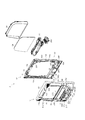
以下、遊技機としての球使用式回胴遊技機の一実施形態を図面に基づいて詳細に説明する。ここでいう球使用式回胴遊技機とは、パチンコ機とスロットマシンとを融合したタイプの遊技機であり、特に遊技球を遊技媒体として使用するスロットマシン仕様の遊技機を指す。図1は球使用式回胴遊技機1の全体を示す正面斜視図であり、図2は正面図であり、図3は後述する固定枠としての外枠2に対して前扉3を開放した状態を示す斜視図であり、図4は前扉3に装着された後述するメインユニット4及び裏機構ユニット5を開放した状態を示す斜視図であり、図5は球使用式回胴遊技機1の背面図である。
Hereinafter, an embodiment of a ball-use spinning machine as a gaming machine will be described in detail with reference to the drawings. The ball-use spinning machine mentioned here is a type of game machine in which a pachinko machine and a slot machine are fused, and particularly refers to a slot machine type game machine that uses a game ball as a game medium. FIG. 1 is a front perspective view showing the entire ball-cylinder-type spinning machine 1, FIG. 2 is a front view, and FIG. 3 is a front door 3 opened with respect to an outer frame 2 as a fixed frame to be described later. FIG. 4 is a perspective view showing a state in which a later-described main unit 4 and back mechanism unit 5 mounted on the front door 3 are opened, and FIG. FIG.
図1〜図5に示すように、球使用式回胴遊技機1は、当該球使用式回胴遊技機1の外殻を形成する外枠2と、外枠2の前部に設けられ外枠2の一側部にて開閉可能に支持された前扉3とを備えている。
As shown in FIGS. 1 to 5, the ball-use type spinning machine 1 includes an outer frame 2 that forms an outer shell of the ball-use type spinning machine 1, and an outer frame 2 provided at the front portion of the outer frame 2. And a front door 3 supported to be opened and closed at one side of the frame 2.
外枠2は、木製の板材により全体として矩形状に構成され、ネジ等の離脱可能な締結具により各板材が組み付けられている。外枠2の下部には樹脂製の幕板飾り6が取着されている。この外枠2を構成する上下の横板は、釘等によって遊技ホールに設けられた遊技機設置島などに固定される。また、左右の縦板は、隣接する球貸装置などに接続される。
The outer frame 2 is formed in a rectangular shape as a whole by a wooden plate material, and each plate material is assembled by a detachable fastener such as a screw. A resin curtain decoration 6 is attached to the lower part of the outer frame 2. The upper and lower horizontal plates constituting the outer frame 2 are fixed to a gaming machine installation island provided in the game hall by nails or the like. The left and right vertical plates are connected to adjacent ball lending devices.
前扉3は、外形が略矩形状のベース枠10と、その前面側に取着される装飾枠11とを主体に構成されている。ベース枠10及び装飾枠11は主に合成樹脂、具体的にはABS(アクリロニトリル−ブタジエン−スチレン)樹脂により構成されている。装飾枠11はベース枠10に対しネジ等の締結具により固定されている。
The front door 3 is mainly composed of a base frame 10 whose outer shape is substantially rectangular and a decorative frame 11 attached to the front side thereof. The base frame 10 and the decorative frame 11 are mainly made of synthetic resin, specifically, ABS (acrylonitrile-butadiene-styrene) resin. The decorative frame 11 is fixed to the base frame 10 with a fastener such as a screw.
球使用式回胴遊技機1の正面から見て、前扉3の左上部及び左下部には上下一対の開閉機構12が設けられている。これに対応して外枠2の左上部及び左下部(幕板飾り左端)には上下一対の支持機構13が設けられている。開閉機構12を支持機構13に組付けることにより、前扉3が外枠2に対し開閉自在に組付けられる。
A pair of upper and lower opening / closing mechanisms 12 are provided on the upper left and lower left of the front door 3 when viewed from the front of the ball-carrying type game machine 1. Correspondingly, a pair of upper and lower support mechanisms 13 are provided at the upper left and lower left (left end of the curtain) of the outer frame 2. By assembling the opening / closing mechanism 12 to the support mechanism 13, the front door 3 is assembled to the outer frame 2 so as to be freely opened and closed.
ここで、開閉機構12及び支持機構13について、両者の関連性をふまえてより詳しく説明する。前扉3の背面側の斜視図である図6等に示すように、開閉機構12は、ベース枠10の左上部及び左下部において左右方向に沿って設けられたベース金具14と、当該ベース金具14の左右方向略中央部において回動自在に軸支された連結アーム15とにより構成されている。
Here, the opening / closing mechanism 12 and the support mechanism 13 will be described in more detail based on the relationship between them. As shown in FIG. 6, which is a perspective view of the back side of the front door 3, the opening / closing mechanism 12 includes a base bracket 14 provided along the left and right directions at the upper left and lower left of the base frame 10, and the base bracket 14 and a connecting arm 15 pivotally supported at a substantially central portion in the left-right direction.
ベース金具14の左端(図6では右端)には上方又は下方へ向け突出した突部16が設けられている。これに対応して、外枠2側の支持機構13の左端には、図3等に示すように、前記突部16が左右方向にスライド自在に嵌め込まれるレール部17が設けられている。レール部17の左端は突部16が抜落ち不能となるよう閉鎖されており、右端は突部16を出し入れ可能に開口している。レール部17の開口側には、突部16の抜落ち防止用の係止片19が設けられている。係止片19は図示しないバネによって常には前方へ付勢された状態に維持されている。
また、連結アーム15の先端部には連結具20が設けられている。これに対応して、支持機構13の右端には、連結アーム15の連結具20が連結される連結部21が設けられている。連結具20が連結部21に対し連結された状態では、連結アーム15が支持機構13に対し回動自在に軸支された状態となる。
A protrusion 16 that protrudes upward or downward is provided at the left end (right end in FIG. 6) of the base metal fitting 14. Correspondingly, at the left end of the support mechanism 13 on the outer frame 2 side, as shown in FIG. 3 and the like, a rail portion 17 into which the protrusion 16 is slidably fitted in the left-right direction is provided. The left end of the rail portion 17 is closed so that the protrusion 16 cannot be pulled out, and the right end is opened so that the protrusion 16 can be taken in and out. On the opening side of the rail portion 17, a locking piece 19 for preventing the protrusion 16 from falling off is provided. The locking piece 19 is always maintained in a state of being biased forward by a spring (not shown).
A connecting tool 20 is provided at the tip of the connecting arm 15. Correspondingly, a connecting portion 21 to which the connecting tool 20 of the connecting arm 15 is connected is provided at the right end of the support mechanism 13. In a state where the connecting tool 20 is connected to the connecting portion 21, the connecting arm 15 is pivotally supported with respect to the support mechanism 13.
外枠2に対する前扉3の装着手順としては、まず、上下とも前扉3側の突部16を外枠2側の係止片19に押し当てる。そして、バネの付勢力に抗して係止片19を没入状態として、突部16をレール部17に嵌め込む。その後、連結アーム15の連結具20を連結部21に対し連結すると、前扉3の装着が完了する。前扉3を開閉させる際には、突部16がレール部17に沿って左右方向にスライドすることにより、前扉3が回動する。
As a procedure for attaching the front door 3 to the outer frame 2, first, the protrusion 16 on the front door 3 side is pressed against the locking piece 19 on the outer frame 2 side in both the upper and lower sides. Then, the locking piece 19 is placed in an immersive state against the biasing force of the spring, and the protrusion 16 is fitted into the rail portion 17. Thereafter, when the connecting tool 20 of the connecting arm 15 is connected to the connecting portion 21, the mounting of the front door 3 is completed. When opening and closing the front door 3, the front door 3 rotates by the protrusion 16 sliding in the left-right direction along the rail portion 17.
次に装飾枠11について詳しく説明する。装飾枠11は、主に、略矩形状の窓孔30を有した窓枠部31と、当該窓枠部31の下方に設けられた上皿構成部32と、当該上皿構成部32の下方に設けられた下皿構成部33とから構成されている。
Next, the decorative frame 11 will be described in detail. The decorative frame 11 mainly includes a window frame portion 31 having a substantially rectangular window hole 30, an upper plate constituting portion 32 provided below the window frame portion 31, and a lower portion of the upper plate constituting portion 32. And a lower plate component 33 provided on the plate.
窓孔30には透明のガラス板34が取付けられている。ここで図6〜図10を参照してより詳しく説明する。図7は正面側から見た前扉3の分解斜視図であり、図8は背面側から見た前扉3の分解斜視図であり、図9はガラス板34等を取外した状態のベース枠10及び装飾枠11を正面側から見た斜視図であり、図10はガラス板34等を取外した状態のベース枠10及び装飾枠11を背面側から見た斜視図である。
A transparent glass plate 34 is attached to the window hole 30. This will be described in more detail with reference to FIGS. 7 is an exploded perspective view of the front door 3 viewed from the front side, FIG. 8 is an exploded perspective view of the front door 3 viewed from the rear side, and FIG. 9 is a base frame with the glass plate 34 and the like removed. 10 and a perspective view of the decorative frame 11 as viewed from the front side, and FIG. 10 is a perspective view of the base frame 10 and the decorative frame 11 with the glass plate 34 and the like removed as viewed from the back side.
ガラス板34は、窓孔30と略同形状をなし、前扉3の背面側より窓孔30の周縁部に当接した状態で取付けられる。また、窓枠部31の内周側には合成樹脂よりなる環状の内周枠35が取着される。内周枠35は、前端部がガラス板34の背面側に当接した状態で、装飾枠11に対しネジ等の締結具により固定される。これにより、ガラス板34は、内周枠35と、窓孔30の周縁部とにより挟持された状態で位置決め固定されることとなる。
The glass plate 34 has substantially the same shape as the window hole 30 and is attached in contact with the peripheral edge of the window hole 30 from the back side of the front door 3. An annular inner peripheral frame 35 made of synthetic resin is attached to the inner peripheral side of the window frame portion 31. The inner peripheral frame 35 is fixed to the decorative frame 11 with a fastener such as a screw in a state where the front end is in contact with the back side of the glass plate 34. Thereby, the glass plate 34 is positioned and fixed in a state of being sandwiched between the inner peripheral frame 35 and the peripheral edge portion of the window hole 30.
また、窓孔30の下方位置かつ上皿構成部32の上方位置にあたる窓枠部31の下辺部には、左右方向に長い略矩形状の開口部36が設けられている。この開口部36には透明の透視パネル37が取付けられている。透視パネル37は、開口部36と略同形状をなし、前扉3の背面側より開口部36の周縁部に当接した状態でネジ等の締結具により装飾枠11に対し固定される。この透視パネル37は、後述する情報表示パネル538に貼付された情報を視認可能とするものである。
In addition, a substantially rectangular opening 36 that is long in the left-right direction is provided at the lower side of the window frame 31 that is located below the window hole 30 and above the upper plate constituting part 32. A transparent see-through panel 37 is attached to the opening 36. The see-through panel 37 has substantially the same shape as the opening 36, and is fixed to the decorative frame 11 by a fastener such as a screw in a state where the see-through panel 37 is in contact with the peripheral edge of the opening 36 from the back side of the front door 3. The fluoroscopic panel 37 makes it possible to visually recognize information pasted on an information display panel 538 described later.
また、装飾枠11にはランプやスピーカ等が設けられている。例えば、図11に示すように、窓枠部31の周縁部のうち、上辺部40には、中央に中央ランプ表示部41、その左右両側方に上部スピーカ42が設けられ、これら中央ランプ表示部41及び上部スピーカ42を覆う装飾カバー43が取着されている。なお、装飾カバー43は、中央ランプ表示部41及び上部スピーカ42に対応して、中央ランプカバー部43a及びスピーカカバー部43bを有している。
The decorative frame 11 is provided with a lamp, a speaker, and the like. For example, as shown in FIG. 11, among the peripheral portions of the window frame portion 31, the upper side portion 40 is provided with a central lamp display portion 41 at the center and upper speakers 42 on the left and right sides thereof. A decorative cover 43 covering 41 and the upper speaker 42 is attached. The decorative cover 43 includes a central lamp cover portion 43 a and a speaker cover portion 43 b corresponding to the central lamp display portion 41 and the upper speaker 42.
また、窓枠部31の左右両側辺部46には、側部ランプ表示部47が設けられるとともに、これを覆う側部ランプカバー48が取着されている。
Further, side lamp display portions 47 are provided on the left and right side portions 46 of the window frame portion 31, and side lamp covers 48 are attached to cover the side lamp display portions 47.
下皿構成部33の後方にはベース枠10において下部スピーカ51(図4等参照)が設けられ、その前面側にあたる下皿構成部33には下部スピーカ51の前面側を覆う下部スピーカカバー52が設けられている。
A lower speaker 51 (see FIG. 4 and the like) is provided in the base frame 10 at the rear of the lower dish constituting portion 33, and a lower speaker cover 52 that covers the front side of the lower speaker 51 is provided on the lower dish constituting portion 33 corresponding to the front side thereof. Is provided.
下皿構成部33の左右両側方には下部ランプ表示部53が設けられるとともに、これを覆う下部ランプカバー54が取着されている。
A lower lamp display unit 53 is provided on both the left and right sides of the lower plate forming unit 33, and a lower lamp cover 54 is attached to cover the lower lamp display unit 53.
これら各種ランプ表示部やスピーカにより、遊技の進行に伴って各種報知や演出が行われる。例えば、後述するように「7」図柄が有効ライン上に揃った場合(ビッグボーナスゲームを獲得した場合)には、それを点灯、点滅等によって報知する。
With these various lamp display units and speakers, various notifications and effects are performed as the game progresses. For example, as described later, when “7” symbols are aligned on the active line (when a big bonus game is acquired), it is notified by lighting, flashing, or the like.
次に上皿構成部32について詳細に説明する。この上皿構成部32に対応する部分、すなわち装飾枠11のうち透視パネル37の下方にあたる部分には、装飾枠11の一部が前方へアーチ状に膨出した膨出部60が形成されている。図7等に示すように、膨出部60の上面には開口部61が形成されており、当該膨出部60は装飾枠11の背面側に貫通している。そして、この膨出部60に対し、前扉3の背面側から上皿ユニット70が取着されている。
Next, the upper plate component 32 will be described in detail. A portion corresponding to the upper plate constituting portion 32, that is, a portion below the perspective panel 37 of the decorative frame 11, is formed with a bulging portion 60 in which a part of the decorative frame 11 is bulged forward. Yes. As shown in FIG. 7 and the like, an opening 61 is formed on the upper surface of the bulging portion 60, and the bulging portion 60 penetrates the back side of the decorative frame 11. The upper plate unit 70 is attached to the bulging portion 60 from the back side of the front door 3.
ここで上皿ユニット70について詳細に説明する。図12は上皿ユニット70の全体を示す斜視図であり、図13は上皿ユニット70の分解斜視図である。また、図14は上皿71の平面図である。
Here, the upper plate unit 70 will be described in detail. FIG. 12 is a perspective view showing the entire upper plate unit 70, and FIG. 13 is an exploded perspective view of the upper plate unit 70. FIG. 14 is a plan view of the upper plate 71.
上皿ユニット70は、本体部となる球貯留手段としての上皿71と、この上皿71に組み付けられるカードユニット操作装置72、球返却機構73、球止め機構74、マックスベットスイッチ75、天井カバー76などからなる。以下、順に上皿71等について詳細に説明していく。
The upper plate unit 70 includes an upper plate 71 serving as a ball storage means serving as a main body, a card unit operating device 72 assembled to the upper plate 71, a ball return mechanism 73, a ball stopper mechanism 74, a max bed switch 75, a ceiling cover. 76 or the like. Hereinafter, the upper plate 71 and the like will be described in detail in order.
上皿71は、後述する払出機構部565より払い出される遊技球や、遊技機設置島などにおいて球使用式回胴遊技機1に併設される球貸サンドなどの球貸装置(プリペイドカード対応又は非対応の球貸装置)のノズルから供給される遊技球を貯留するとともに、後述する取込装置300へ供給する機能を有している。
The upper plate 71 is a ball lending device (prepaid card compatible or non-paid) such as a game ball paid out from a payout mechanism unit 565, which will be described later, or a ball lending sand attached to the ball-use type revolving game machine 1 on a gaming machine installation island or the like. The game ball supplied from the nozzle of the corresponding ball lending device) is stored and supplied to the take-in device 300 described later.
上皿71は、合成樹脂材料により左右方向に長く上方に開口した略箱状に形成されており、その内部に遊技球を貯留可能となっている。また、本実施形態における上皿71は、その前後幅が比較的幅広に設定されており、膨出部60への取着時においては前後方向略中央部より前側が上記透視パネル37の位置より前方に位置し、後側部分が透視パネル37より後方に位置する。
The upper plate 71 is formed in a substantially box shape that is long in the left-right direction and is opened upward by a synthetic resin material, and can store a game ball therein. Further, the upper plate 71 in the present embodiment is set to have a relatively wide front-rear width, and when attached to the bulging portion 60, the front side from the substantially central portion in the front-rear direction from the position of the fluoroscopic panel 37. It is located in the front and the rear part is located behind the fluoroscopic panel 37.
上皿71の開口部周縁にはフランジ79が設けられており、上皿ユニット70はこのフランジ79が膨出部60の開口部61周縁に載置された状態で取付けられる。上皿71の左右側壁部71a,71bには固定部88が設けられており、上皿71はこの固定部88を介してネジ等により装飾枠11に対し固定される。
A flange 79 is provided on the periphery of the opening of the upper plate 71, and the upper plate unit 70 is attached in a state where the flange 79 is placed on the periphery of the opening 61 of the bulging portion 60. Fixing portions 88 are provided on the left and right side wall portions 71 a and 71 b of the upper plate 71, and the upper plate 71 is fixed to the decorative frame 11 with screws or the like through the fixing portions 88.
上皿71の奥壁部80の左端には切欠き状の受口部81が形成されており、この受口部81を介して払出手段としての払出機構部565から払い出される遊技球が上皿71へ排出される。
A notch-shaped receiving portion 81 is formed at the left end of the back wall portion 80 of the upper plate 71, and a game ball paid out from a payout mechanism portion 565 serving as a payout means is received through the receiving portion 81. It is discharged to 71.
一方、最下流側にあたる底部82の右端には、前後方向略中央部より後側部分すなわち透視パネル37より後方に位置する後側部分において、下方へ開口した取込口83が形成されている。この取込口83は後述する取込装置300の上方に位置する。
On the other hand, at the right end of the bottom portion 82 corresponding to the most downstream side, an intake port 83 opened downward is formed in a rear portion from the substantially central portion in the front-rear direction, that is, a rear portion located rearward of the fluoroscopic panel 37. This intake port 83 is located above the intake device 300 described later.
上皿71の底部82は球使用式回胴遊技機1正面から見て左側から右側に向けて下方へ傾斜しており、上皿71上の遊技球は取込口83へ向けて流れ、この取込口83を介して取込装置300へと導かれる。
The bottom portion 82 of the upper plate 71 is inclined downward from the left side to the right side when viewed from the front of the ball-use spinning machine 1, and the game ball on the upper plate 71 flows toward the intake port 83. It is guided to the capture device 300 via the intake port 83.
上皿71の左右方向略中央部より左側部分すなわち上流側部分には、前後幅が比較的広く、より多くの遊技球を貯留できるスペース(以下、貯留部84という)が確保されている。
A space (hereinafter referred to as a storage portion 84) in which a larger number of game balls can be stored is secured in the left side portion, that is, the upstream side portion of the upper plate 71 from the substantially central portion in the left-right direction.
一方、上皿71の右側部分すなわち下流側部分には、取込口83へ通じる前後幅の比較的狭い整流部85が設けられている。この整流部85は、取込口83ひいては取込装置300に向けて遊技球を整列しつつ誘導する機能を有する。より詳しくは、上皿71の奥壁部80の右端部分は後方に向けて膨出しており、これに伴い整流部85は下流側に向け前後幅が広がった構成となっている。
On the other hand, on the right side portion, that is, the downstream side portion of the upper plate 71, a rectifying portion 85 having a relatively narrow front-rear width leading to the intake port 83 is provided. The rectifying unit 85 has a function of guiding the game balls while aligning them toward the intake port 83 and thus toward the capture device 300. More specifically, the right end portion of the back wall portion 80 of the upper plate 71 bulges toward the rear, and accordingly, the rectifying portion 85 has a configuration in which the front-rear width is widened toward the downstream side.
また、整流部85の下流側には、奥壁部80が膨出した区間に対応して、2つの誘導リブ86が設けられている。これにより、遊技球を1列に整列させつつ取込口83へ向けて流下させる3条の整流球通路87が形成される。なお、誘導リブ86は奥壁部80の膨出部分の形状に合わせて前後方向に緩やかに湾曲するとともに、下流側に向けて先太りした形状となっている。そして、3つの整流球通路87は下流側で左右方向に沿って延在し前後方向に等間隔で並んでいる。この3つの整流球通路87の最下流部における配置間隔は、取込装置300の3つの取込ユニット305の配置間隔に合わせたものである。
In addition, two guide ribs 86 are provided on the downstream side of the rectifying unit 85 so as to correspond to the section in which the back wall 80 is bulged. As a result, three rectifying sphere passages 87 are formed that allow the game balls to flow toward the intake port 83 while being aligned in a line. The guide rib 86 is gently curved in the front-rear direction in accordance with the shape of the bulging portion of the back wall 80, and has a shape that tapers toward the downstream side. The three rectifying ball passages 87 extend along the left-right direction on the downstream side and are arranged at equal intervals in the front-rear direction. The arrangement interval at the most downstream portion of the three rectifying ball passages 87 is set in accordance with the arrangement interval of the three acquisition units 305 of the acquisition device 300.
上記整流部85の前方には、整流部85の傾斜方向とは逆方向、すなわち左側に向け下方へ傾斜した逆傾斜部90が設けられている。従って、整流部85では、当該整流部85と逆傾斜部90との間に形成された段差部91により、遊技球の前方への動きが規制される。また、逆傾斜部90の奥側には仕切リブ92が突設されている。これにより、逆傾斜部90から整流部85側へ遊技球が落下し、整流部85において遊技球が重畳されることを防止している。
In front of the rectifying unit 85, a reverse inclined part 90 is provided which is inclined in the direction opposite to the inclination direction of the rectifying part 85, that is, downward toward the left side. Therefore, in the rectifying unit 85, the forward movement of the game ball is restricted by the step portion 91 formed between the rectifying unit 85 and the reverse inclined portion 90. In addition, a partition rib 92 is projected on the back side of the reverse inclined portion 90. As a result, the game ball is dropped from the reverse inclined portion 90 to the rectifying unit 85, and the game ball is prevented from being superimposed on the rectifying unit 85.
さらに、逆傾斜部90の手前側には奥側に向け下方に傾斜した奥向き傾斜部95が形成されている。逆傾斜部90と奥向き傾斜部95との間には段差96が形成され、逆傾斜部90から前方への遊技球の動きが規制されている。同様に、上皿71の前壁部98の頂部と奥向き傾斜部95との間には段差99があり、奥向き傾斜部95から前方への遊技球の動きが規制されている。
Further, a rearward inclined portion 95 that is inclined downward toward the back side is formed on the near side of the reverse inclined portion 90. A step 96 is formed between the reverse inclined portion 90 and the rearward inclined portion 95, and the movement of the game ball forward from the reverse inclined portion 90 is restricted. Similarly, there is a step 99 between the top portion of the front wall portion 98 of the upper plate 71 and the backward inclined portion 95, and the movement of the game ball forward from the backward inclined portion 95 is restricted.
奥向き傾斜部95の左方にはマックスベットスイッチ75が取着されている。より詳しくは、奥向き傾斜部95の左方の背面側にはマックスベットスイッチ75を取付けるための収容凹部100が形成されており、ここにマックスベットスイッチ75が取着されている。
A max bed switch 75 is attached to the left of the rearward inclined portion 95. More specifically, an accommodation recess 100 for attaching a max bed switch 75 is formed on the left rear side of the back-facing inclined portion 95, and the max bed switch 75 is attached thereto.
マックスベットスイッチ75は、上皿71に開口形成されたボタン孔102を介して上皿71の上面側に露出したマックスベットボタン78と、当該マックスベットボタン78の押圧操作を検出する検出センサを搭載し収容凹部100に取付けられるスイッチ基板77とからなる。また、マックスベットボタン78内には図示しないLEDが設けられており、当該LEDが点灯表示されることによって押圧操作が可能であることが報知され、消灯表示によって押圧操作が不能であることが報知されるようになっている。
The max bet switch 75 is equipped with a max bet button 78 exposed on the upper surface side of the upper plate 71 through a button hole 102 formed in the upper plate 71 and a detection sensor for detecting a pressing operation of the max bet button 78. And a switch board 77 attached to the housing recess 100. Further, an LED (not shown) is provided in the max bet button 78. When the LED is turned on, it is notified that the pressing operation is possible, and when the LED is turned off, the pressing operation is not possible. It has come to be.
また、逆傾斜部90及び奥向き傾斜部95の右方かつ取込口33の前方位置には、その背面側においてカードユニット操作装置72を取付けるための収容凹部110が形成されている。この収容凹部110に対応する上皿71の上面部は膨出しており、この膨出した部位にカードユニット操作装置72を操作するための操作面111が形成される。
An accommodation recess 110 for attaching the card unit operation device 72 is formed on the back side of the reverse inclined portion 90 and the back-facing inclined portion 95 and on the front side of the intake port 33. The upper surface portion of the upper plate 71 corresponding to the housing recess 110 is bulged, and an operation surface 111 for operating the card unit operation device 72 is formed at the bulged portion.
ここでカードユニット操作装置72について詳しく説明する。カードユニット操作装置72は、プリペイドカード対応の球貸装置のカードユニットを操作するものであり、ベース部材112と、当該ベース部材112に搭載されたカードユニット操作基板113とを備えている。カードユニット操作基板113には、球貸スイッチ115と、返却スイッチ116と、7セグメントLEDよりなる3桁表示の度数表示部119とが設けられている。さらに、球貸スイッチ115を操作するための球貸ボタン117と、返却スイッチ116を操作するための返却ボタン118とが、操作面111側に載置されている。
Here, the card unit operating device 72 will be described in detail. The card unit operation device 72 operates a card unit of a prepaid card-compatible ball lending device, and includes a base member 112 and a card unit operation board 113 mounted on the base member 112. The card unit operation board 113 is provided with a ball lending switch 115, a return switch 116, and a 3-digit display frequency display unit 119 composed of 7-segment LEDs. Further, a ball lending button 117 for operating the ball lending switch 115 and a return button 118 for operating the return switch 116 are placed on the operation surface 111 side.
遊技ホールにおいて球使用式回胴遊技機1の側方に配置される球貸装置に紙幣やカード等を投入した状態でカードユニット操作装置72が操作されると、その操作に応じて遊技球の貸出しが行われる。球貸ボタン117はカード等(記録媒体)に記録された情報に基づいて貸出球(貸球)を得るために操作されるものであり、カード等に残額が存在する限りにおいて貸出球が上皿71に供給される。返却ボタン118はカードユニットに挿入されたカード等の返却を求める際に操作されるものである。度数表示部119はカード等の残額情報を表示するものである。なお、プリペイドカード非対応の球貸装置等からカードユニットを介さずに上皿71へ遊技球が直接貸出される遊技機、いわゆる現金機ではカードユニット操作装置72が不要となる。この場合、操作面111(又は上カバー141)部分に装飾シール等が貼付される。つまり、本実施形態における球使用式回胴遊技機1は、プリペイドカード対応又は非対応の球貸装置どちらにも対応するように構成されている。
When the card unit operating device 72 is operated in a state where a bill or a card is inserted into a ball lending device disposed on the side of the ball-carrying revolving game machine 1 in the game hall, Lending is done. The ball lending button 117 is operated to obtain a lending ball (lending ball) based on information recorded on a card or the like (recording medium). 71. The return button 118 is operated when requesting the return of a card or the like inserted into the card unit. The frequency display unit 119 displays remaining amount information such as a card. In addition, the card unit operating device 72 is not required in a game machine in which a game ball is lent directly to the upper plate 71 from a ball lending device or the like that does not support a prepaid card without passing through a card unit. In this case, a decorative seal or the like is affixed to the operation surface 111 (or the upper cover 141). In other words, the ball-use spinning machine 1 according to the present embodiment is configured to support both prepaid card-compatible and non-compatible ball lending devices.
収容凹部110にはボス123が設けられており、当該ボス123に対しベース部材112がネジ等の締結具により固定される。
The housing recess 110 is provided with a boss 123, and the base member 112 is fixed to the boss 123 with a fastener such as a screw.
操作面111には、度数表示部119に対応した表示部用開口部131、球貸ボタン117に対応したボタン孔132、返却ボタン118に対応したボタン孔133が、それぞれ収容凹部110に貫通するように設けられている。そして、球貸ボタン117及び返却ボタン118から垂下した図示しない軸部がボタン孔132,133を介して各スイッチ115,116に当接している。これにより各スイッチ115,116が操作される。
On the operation surface 111, a display portion opening 131 corresponding to the frequency display portion 119, a button hole 132 corresponding to the ball lending button 117, and a button hole 133 corresponding to the return button 118 pass through the receiving recess 110. Is provided. A shaft portion (not shown) suspended from the ball lending button 117 and the return button 118 is in contact with the switches 115 and 116 through the button holes 132 and 133. As a result, the switches 115 and 116 are operated.
また、操作面111側には、その上面を覆う下カバー140と、当該下カバー140の上面を覆う上カバー141とが取付けられている。
On the operation surface 111 side, a lower cover 140 that covers the upper surface and an upper cover 141 that covers the upper surface of the lower cover 140 are attached.
下カバー140の前側及び後側にはそれぞれ一対の係止爪143,144が設けられており、この係止爪143,144を上皿71に係止することにより下カバー140が固定される。
A pair of locking claws 143 and 144 are provided on the front side and the rear side of the lower cover 140, respectively, and the lower cover 140 is fixed by locking the locking claws 143 and 144 to the upper plate 71.
上カバー141は、下カバー140の上側から、前側に設けられた一対の係止爪145を皿体71に係止するとともに、後側をネジ等により固定することにより、上皿71に対し固定される。
The upper cover 141 is fixed to the upper plate 71 by locking a pair of locking claws 145 provided on the front side to the plate body 71 from the upper side of the lower cover 140 and fixing the rear side with screws or the like. Is done.
下カバー140は、内部を視認困難とするよう着色の施された半透明の合成樹脂材料により形成されている。但し、度数表示部119に対応する部分は透視可能に構成されている。また、球貸ボタン117及び返却ボタン118に対応した位置にはボタン孔151,152が設けられている。
The lower cover 140 is formed of a translucent synthetic resin material that is colored so that the inside is difficult to see. However, the part corresponding to the frequency display part 119 is configured to be seen through. In addition, button holes 151 and 152 are provided at positions corresponding to the ball lending button 117 and the return button 118.
上カバー141は、無色透明の合成樹脂材料により形成されており、下カバー140の表面に記載される各種情報(例えば「球貸」等の文字)を視認可能となっている。さらに、上下カバー140,141を透かして度数表示部119を視認可能となる。また、球貸ボタン117及び返却ボタン118に対応した位置にはボタン孔153,154が設けられている。従って、下カバー140のボタン孔151,152、及び、上カバー141のボタン孔153,154を介して、球貸ボタン117及び返却ボタン118が操作可能なように露出した状態となる。
The upper cover 141 is formed of a colorless and transparent synthetic resin material, and various information (for example, characters such as “ball rental”) described on the surface of the lower cover 140 can be visually recognized. Further, the frequency display unit 119 can be visually recognized through the upper and lower covers 140 and 141. In addition, button holes 153 and 154 are provided at positions corresponding to the ball lending button 117 and the return button 118. Accordingly, the ball lending button 117 and the return button 118 are exposed so as to be operable through the button holes 151 and 152 of the lower cover 140 and the button holes 153 and 154 of the upper cover 141.
また、上カバー141の上面は、前側が前方に向けて下方へ傾斜し、後側が後方に向けて下方へ傾斜した構成となっており、遊技球を停留させない構成となっている。
Further, the upper surface of the upper cover 141 is configured such that the front side is inclined downward toward the front and the rear side is inclined downward toward the rear, so that the game ball is not stopped.
次にカードユニット操作装置72の下側に取付けられる球返却機構73について詳しく説明する。球返却機構73は取込装置300の返却シャッタ341を駆動させ、上皿71に貯留されている遊技球を後述する下皿253へ排出させるために操作されるものである。
Next, the ball return mechanism 73 attached to the lower side of the card unit operation device 72 will be described in detail. The ball return mechanism 73 is operated to drive the return shutter 341 of the take-in device 300 to discharge the game balls stored in the upper plate 71 to the lower plate 253 described later.
球返却機構73は、各部材の取付台となるベースカバー160と、当該ベースカバー160の上面側に回動自在に軸支された第1回動部材161と、当該第1回動部材161より後方位置において回動自在に軸支された第2回動部材162と、第1回動部材161の前方位置に設けられた返却操作手段としての返却レバー163とを備えている(図13参照)。ベースカバー160は、上記カードユニット操作装置72のベース部材112の裏面に設けられたボス165に対しネジ等により固定される。
The ball return mechanism 73 includes a base cover 160 serving as a mounting base for each member, a first rotating member 161 pivotally supported on the upper surface side of the base cover 160, and the first rotating member 161. A second rotating member 162 pivotally supported at the rear position and a return lever 163 as a return operation means provided at a front position of the first rotating member 161 are provided (see FIG. 13). . The base cover 160 is fixed to a boss 165 provided on the back surface of the base member 112 of the card unit operating device 72 with a screw or the like.
また、第1回動部材161及び第2回動部材162、第1回動部材161及び返却レバー163は、それぞれ連動可能に係合されている。そして、返却レバー163の左右方向の動きに連動して第1回動部材161が回動し、第1回動部材161の回動に連動して第2回動部材162が回動する。なお、第1回動部材161の前片部と前記ボス165との間にはコイルばね180が掛けられており、通常時には返却レバー163が右側に付勢されている。
Moreover, the 1st rotation member 161, the 2nd rotation member 162, the 1st rotation member 161, and the return lever 163 are each engaged so that interlocking | linkage is possible. Then, the first rotating member 161 rotates in conjunction with the movement of the return lever 163 in the left-right direction, and the second rotating member 162 rotates in conjunction with the rotation of the first rotating member 161. A coil spring 180 is hung between the front piece of the first rotating member 161 and the boss 165, and the return lever 163 is normally urged to the right.
また、上記上皿構成部32の膨出部60の右下部には返却レバー163に対応して開口部181が設けられており、返却レバー163が遊技者により操作可能なように球使用式回胴遊技機1前面側に露出している。
In addition, an opening 181 is provided in the lower right portion of the bulging portion 60 of the upper plate constituting portion 32 corresponding to the return lever 163 so that the return lever 163 can be operated by the player. It is exposed on the front side of the trunk game machine 1.
そして、遊技者が上皿71に貯留されている遊技球を取り出そうとした場合には、コイルばね180の付勢力に抗して返却レバー163を左方へスライドさせる。これに連動して、第1回動部材161が、球返却機構73の上方から見て時計回りに回動するとともに、第2回動部材162が反時計回りに回動する。この結果、第2回動部材162の右片部により取込装置300の返却シャッタ341が操作され、上皿71内の遊技球が下皿253へ排出される。返却シャッタ341の動作態様の詳細については後述する。
When the player tries to take out the game ball stored in the upper plate 71, the return lever 163 is slid leftward against the biasing force of the coil spring 180. In conjunction with this, the first rotating member 161 rotates clockwise as viewed from above the ball return mechanism 73, and the second rotating member 162 rotates counterclockwise. As a result, the return shutter 341 of the capture device 300 is operated by the right piece of the second rotating member 162, and the game balls in the upper plate 71 are discharged to the lower plate 253. Details of the operation mode of the return shutter 341 will be described later.
次に上皿71の裏面側に取付けられた球止め機構74について説明する。球止め機構74は、取込口83近傍の整流部85裏面側に取付けられており、当該球止め機構74の内部機構を下側から覆うベースカバー185と、上皿71の裏面に略当接した状態で左右方向にスライド自在に設けられたスライドベース186と、当該スライドベース186を操作する操作レバー187とを備えている。ベースカバー185は上皿71の裏面に対しネジ等により固定される。
Next, the ball stop mechanism 74 attached to the back side of the upper plate 71 will be described. The ball stopper mechanism 74 is attached to the back surface side of the rectifying unit 85 in the vicinity of the intake port 83, and is substantially in contact with the base cover 185 that covers the internal mechanism of the ball stopper mechanism 74 from below and the back surface of the upper plate 71. In this state, a slide base 186 that is slidable in the left-right direction and an operation lever 187 for operating the slide base 186 are provided. The base cover 185 is fixed to the back surface of the upper plate 71 with screws or the like.
また、球使用式回胴遊技機1の背面側から見て左側にあたる、スライドベース186の取込口83側には3つの突出部205が設けられている。各突出部205は、上記整流部85の裏面側において3条の整流球通路87に沿って形成された図示しない溝部に嵌め込まれており、スライドベース186のスライド動作に伴って突出部205が取込口83内外に出没可能となっている。
In addition, three projecting portions 205 are provided on the side of the intake port 83 of the slide base 186, which is on the left side when viewed from the back side of the ball-carrying spinning machine 1. Each protrusion 205 is fitted into a groove (not shown) formed along the three straightening ball passages 87 on the back surface side of the flow straightening portion 85, and the protrusion 205 is taken by the slide operation of the slide base 186. It is possible to go in and out of the entrance 83.
通常時、スライドベース186は、球使用式回胴遊技機1の背面側から見て右側によっており、突出部205が取込口83から没した状態となっている。この状態から、操作レバー187を球使用式回胴遊技機1の背面側から見て時計回りに回動させることにより、スライドベース186が取込口83側へスライドし、突出部205が取込口83内に突出した状態となる。この状態では、突出部205と後述する箱体212の底壁部231との間隔が遊技球の通過不能な間隔となり、遊技球が取込口83から落下不能となる。
In normal times, the slide base 186 is on the right side when viewed from the back side of the ball-use spinning machine 1, and the protruding portion 205 is in a state of being submerged from the intake port 83. From this state, when the operating lever 187 is rotated clockwise as viewed from the back side of the ball-carrying type revolving gaming machine 1, the slide base 186 slides toward the intake port 83, and the protruding portion 205 is taken in. A state of protruding into the mouth 83 is obtained. In this state, the interval between the protruding portion 205 and the bottom wall portion 231 of the box 212 described later is an interval at which the game ball cannot pass, and the game ball cannot be dropped from the intake port 83.
球止め解除する際には、操作レバー187を球使用式回胴遊技機1の背面側から見て反時計回りに回動させる。これにより、スライドベース186が右方へスライドし、突出部205が取込口83から没した状態となる。これにより遊技球が取込口83へ落下可能となる。
When releasing the ball stop, the operation lever 187 is rotated counterclockwise as viewed from the back side of the ball-use spinning machine 1. As a result, the slide base 186 slides to the right, and the protruding portion 205 is in a state of being submerged from the intake port 83. As a result, the game ball can fall into the intake port 83.
次に上皿71に組付けられる天井カバー76について説明する。天井カバー76は、上皿71と装飾枠11との間に隙間を生じさせないために設けられたものであり、透視パネル37の位置より後側部分、すなわち上皿71の前後方向略中央部より後側部分の天井部分を覆うように設けられている。
Next, the ceiling cover 76 assembled to the upper plate 71 will be described. The ceiling cover 76 is provided so as not to create a gap between the upper plate 71 and the decorative frame 11, and is located on the rear side from the position of the perspective panel 37, that is, from the substantially central portion in the front-rear direction of the upper plate 71. It is provided so as to cover the ceiling portion of the rear portion.
天井カバー76は、上皿71の奥壁部80に沿って左右方向略全域に設けられるとともに後方へ向け下方に傾斜した天板体210と、当該天板体210の左右両側部から下方へ垂設された側壁部211と、天板体210とは別体で設けられ、当該天板体210に組付けられる箱体212とからなる。天板体210の後縁部及び側壁部211が、上皿71の奥壁部80及び左右側壁部71a,71bに対しそれぞれネジ等により固定されることにより、天井カバー76が上皿71に対し固定される。
The ceiling cover 76 is provided in substantially the entire region in the left-right direction along the back wall 80 of the upper plate 71 and is inclined downward toward the rear, and is suspended downward from the left and right sides of the top plate 210. The provided side wall part 211 and the top plate 210 are provided separately, and are composed of a box 212 assembled to the top plate 210. By fixing the rear edge portion and the side wall portion 211 of the top plate body 210 to the rear wall portion 80 and the left and right side wall portions 71a and 71b of the upper plate 71 with screws or the like, the ceiling cover 76 is attached to the upper plate 71. Fixed.
また、天板体210は、その前縁部が装飾枠11の背面側にネジ等により固定される。天板体210の前縁部には前方へ突出したリブ216が設けられており、天板体210の前縁部が固定される際には、このリブ216が装飾枠11の背面側に設けられた図示しない溝部に係合された状態となる。これにより、天板体210と装飾枠11との隙間から球使用式回胴遊技機1内部へ針金等を侵入させ、内部機器を操作するといった不正行為の防止が図られている。
Further, the front edge of the top plate 210 is fixed to the back side of the decorative frame 11 with screws or the like. A rib 216 projecting forward is provided at the front edge of the top plate 210, and this rib 216 is provided on the back side of the decorative frame 11 when the front edge of the top plate 210 is fixed. It will be in the state engaged with the groove part which is not shown in figure. This prevents illegal acts such as operating a device by inserting a wire or the like into the ball-use spinning machine 1 from the gap between the top plate 210 and the decorative frame 11.
天板体210の右端部近傍には、上記整流球通路87及び取込口83に対応してその上方位置に開口部217が設けられており、この開口部217の上方から上記箱体212が嵌め込まれている。
In the vicinity of the right end of the top plate 210, an opening 217 is provided at an upper position corresponding to the rectifying ball passage 87 and the intake port 83, and the box 212 is disposed above the opening 217. It is inserted.
箱体212は、上方に開口した略箱状をなし、その開口部の周縁形状が前記天板体210の開口部217の周縁形状と略同一形状となっている。また、箱体212の開口周縁部にはフランジ218が形成されており、これが天板体210の開口部217周縁に形成された段差部に係合することにより、箱体212が天板体210に対し位置決めされた状態で組付けられる。そして、メインユニット4が上方位置に配置された際には、当該メインユニット4により上方への移動が規制される。換言すれば、メインユニット4が上方位置より移動した場合には、箱体212の上方への規制がなくなるため、前扉3の背面側から箱体212を容易に取外すことができる。これにより、整流球通路87や、取込口83の下方に位置する取込装置300等の清掃作業や点検、修理等を行うことができ、メンテナンス性の向上が図られる。
The box 212 has a substantially box shape opened upward, and the peripheral shape of the opening is substantially the same as the peripheral shape of the opening 217 of the top plate 210. In addition, a flange 218 is formed on the opening peripheral edge of the box body 212, and this engages with a stepped portion formed on the peripheral edge of the opening 217 of the top plate 210, whereby the box 212 is fixed to the top plate 210. Assembled in a state of being positioned with respect to. When the main unit 4 is disposed at the upper position, the main unit 4 restricts the upward movement. In other words, when the main unit 4 is moved from the upper position, there is no restriction on the upper side of the box body 212, so that the box body 212 can be easily detached from the back side of the front door 3. Thereby, cleaning work, inspection, repair, etc. of the current-carrying ball passage 87 and the intake device 300 located below the intake port 83 can be performed, and the maintainability is improved.
箱体212の組付け状態において、その底壁部231は取込装置300(停留傾斜部308)や整流球通路87の天井部を構成する(図16参照)。これにより、後述するように上記整流球通路87により案内される遊技球を一列で通過させ、取込装置300内へと通じる球通路が形成される。
In the assembled state of the box 212, the bottom wall portion 231 constitutes the ceiling portion of the take-in device 300 (stopping inclined portion 308) and the rectifying ball passage 87 (see FIG. 16). Thereby, as described later, the game balls guided by the rectifying ball passage 87 are passed in a row, and a ball passage leading to the take-in device 300 is formed.
また、箱体212により、上皿71内を流れる遊技球は最終的には上下に積み重なることなく下流側の整流球通路87へ流下していく。従って、整流部85に多量の遊技球が流れ込んできたとしても、遊技球の噛み込みが抑制され、取込口83近傍における球詰まりが解消されるようになっている。
Further, the game balls flowing in the upper plate 71 are finally caused to flow down to the downstream straightening passage 87 without being stacked up and down by the box 212. Therefore, even if a large amount of game balls flow into the rectifying unit 85, the biting of the game balls is suppressed, and the clogging of the balls in the vicinity of the intake port 83 is eliminated.
さて、一般的に、遊技ホールでは球使用式回胴遊技機1の左側に球貸装置が設けられており、プリペイドカード対応の球貸装置の場合、上述したように紙幣やカード等を投入した状態でカードユニット操作装置72が操作されると、その操作に応じて遊技球の貸出が行われる。実際には球貸装置に設けられたノズルを介して遊技球が球使用式回胴遊技機1(上皿71)に供給される。このノズルは、通常、回動可能かつ上方に跳ね上げ可能に構成されている。そこで、本実施形態では、ノズルが上皿71に向いた球供給位置(貯留部84上方)にある場合に、このノズルと、装飾枠11とが干渉しない構成を採用している。具体的には、装飾枠11における上皿構成部32より上方でかつ透視パネル37の側方にあたるノズル対応箇所に、切欠き状の凹部250を設けている。
Now, generally, in the game hall, a ball lending device is provided on the left side of the ball-carrying revolving game machine 1, and in the case of a ball lending device compatible with a prepaid card, a bill or a card is inserted as described above. When the card unit operating device 72 is operated in the state, gaming balls are lent according to the operation. Actually, a game ball is supplied to the ball-use type spinning machine 1 (upper plate 71) through a nozzle provided in the ball lending device. This nozzle is normally configured to be rotatable and to be able to be flipped upward. Therefore, in the present embodiment, when the nozzle is located at the ball supply position facing the upper plate 71 (above the storage portion 84), a configuration is employed in which the nozzle and the decorative frame 11 do not interfere with each other. Specifically, a notch-shaped recess 250 is provided at a nozzle-corresponding portion that is above the upper plate constituting portion 32 in the decorative frame 11 and that is on the side of the transparent panel 37.
次に下皿構成部33について図1等を参照して詳しく説明する。装飾枠11の下部には前方へ膨出した膨出部252が設けられており、当該膨出部252に遊技球を貯留するための下皿253が取付けられている。また、下皿構成部33(下皿253)の奥壁部254の中央部には下部スピーカ51用のスピーカ開口部255が設けられており、このスピーカ開口部255に装飾枠11の背面側から上記下部スピーカカバー52が取付けられている(図8等参照)。また、球使用式回胴遊技機1の正面から見て、スピーカ開口部255の右方には排出口257が形成されている。
Next, the lower plate component 33 will be described in detail with reference to FIG. A bulging portion 252 that bulges forward is provided at the lower portion of the decorative frame 11, and a lower plate 253 for storing game balls is attached to the bulging portion 252. In addition, a speaker opening 255 for the lower speaker 51 is provided at the center of the back wall portion 254 of the lower plate constituting portion 33 (lower plate 253), and the speaker opening 255 is provided on the speaker opening portion 255 from the back side of the decorative frame 11. The lower speaker cover 52 is attached (see FIG. 8 and the like). In addition, a discharge port 257 is formed on the right side of the speaker opening 255 when viewed from the front of the ball-use spinning machine 1.
また、下皿構成部33(下皿253及び膨出部252)には球抜き孔260が形成されている。この球抜き孔260は、通常、膨出部252の内部においてスライド自在に設けられた開閉弁261により閉塞されている。そして、膨出部252の前面に設けられた球抜きレバー262を操作してスライドした場合に、球抜き孔260が開放され、下皿253に貯留されていた遊技球が球抜き孔260から下方へ排出される。
In addition, a ball punching hole 260 is formed in the lower plate component 33 (the lower plate 253 and the bulging portion 252). The ball removal hole 260 is normally closed by an on-off valve 261 slidably provided inside the bulging portion 252. When the ball removal lever 262 provided on the front surface of the bulging portion 252 is operated and slid, the ball removal hole 260 is opened, and the game balls stored in the lower plate 253 are moved downward from the ball removal hole 260. Is discharged.
次に装飾枠11に設けられた各種操作手段について詳しく説明する。
Next, various operation means provided on the decorative frame 11 will be described in detail.
上皿構成部32の膨出部60の前面左側には後述する各リール511〜513を回転開始させるための始動操作手段としてのスタートレバースイッチ268が設けられている。
A start lever switch 268 is provided on the left side of the front surface of the bulging portion 60 of the upper plate forming portion 32 as a starting operation means for starting rotation of reels 511 to 513 described later.
スタートレバースイッチ268は、膨出部60の前面側に突出したスタートレバー268aと、当該スタートレバー268aの操作を検出する検出スイッチを搭載し膨出部60の背面側に取付けられるスイッチ基板268bとからなる。
The start lever switch 268 includes a start lever 268a protruding to the front side of the bulging portion 60, and a switch board 268b mounted with a detection switch for detecting the operation of the start lever 268a and attached to the back side of the bulging portion 60. Become.
スタートレバースイッチ268の右方には、回転中の各リール511,512,513を個別に停止させるための停止操作手段としてのストップボタンスイッチ271,272,273が設けられている。各ストップボタンスイッチ271〜273は、それぞれ停止対象となるリール511〜513の下方に位置している。各ストップボタンスイッチ271〜273は、左リール511が回転を開始してから所定時間が経過すると停止させることが可能な状態となり、かかる状態中には各ボタン内に設けられた図示しないLEDが点灯表示されることによって停止操作が可能であることが報知され、回転が停止すると消灯されるようになっている。
On the right side of the start lever switch 268, stop button switches 271, 272, 273 are provided as stop operation means for individually stopping the rotating reels 511, 512, 513. Each of the stop button switches 271 to 273 is located below the reels 511 to 513 to be stopped. Each stop button switch 271 to 273 can be stopped when a predetermined time elapses after the left reel 511 starts rotating, and an LED (not shown) provided in each button is lit during this state. By displaying, it is notified that the stop operation is possible, and when the rotation stops, it is turned off.
ストップボタンスイッチ271,272,273は、膨出部60の前面側に露出したストップボタン271a,272a,273aと、当該ストップボタン271a〜273aの押圧操作を個別に検出する検出センサを搭載し膨出部60の背面側に取付けられる図示しないスイッチ基板とからなる。
The stop button switches 271, 272, 273 are mounted with stop buttons 271 a, 272 a, 273 a exposed on the front surface side of the bulging portion 60 and detection sensors that individually detect pressing operations of the stop buttons 271 a-273 a. It consists of a switch board (not shown) attached to the back side of the unit 60.
この他、操作手段としては、遊技球を投入するため(ベット操作を行うための)の入力手段を構成するボタン状の各種ベットスイッチが設けられている。各ベットスイッチは、共に遊技媒体(又は記憶遊技媒体)たる遊技球を必要数分だけ投入するためのものである。本実施の形態では、1ベットスイッチ274と上述したマックスベットスイッチ75とが設けられている。
In addition, as the operation means, various button-shaped bet switches constituting input means for inserting a game ball (for performing a bet operation) are provided. Each bet switch is used to insert a required number of game balls as game media (or memory game media). In the present embodiment, a 1-bet switch 274 and the above-described max bet switch 75 are provided.
1ベットスイッチ274は上記透視パネル37の左方位置に設けられており、マックスベットスイッチ75は、上述したように上皿ユニット70の手前やや左側で、スタートレバースイッチ268の上方やや右側に位置している。
The 1-bet switch 274 is provided on the left side of the see-through panel 37, and the max-bet switch 75 is located slightly before the upper plate unit 70 and slightly above the start lever switch 268 as described above. ing.
1ベットスイッチ274は、取付部275の前面側に露出した1ベットボタン274aと、当該1ベットボタン274aの押圧操作を検出する検出センサを搭載し取付部275の背面側に取付けられるスイッチ基板274bとからなる。
The 1-bet switch 274 includes a 1-bet button 274a exposed on the front surface side of the mounting portion 275, and a switch board 274b mounted on the back surface side of the mounting portion 275 with a detection sensor for detecting a pressing operation of the 1-bet button 274a. Consists of.
1ベットスイッチ274に関しては、1回押圧操作される毎に、5個の遊技球が投入されるよう設定されている。より詳しくは、1ベットスイッチ274の1回の押圧操作で、上皿71の遊技球が「5個」ずつ取り込まれる。
The 1-bet switch 274 is set so that five game balls are inserted each time the button is pressed. More specifically, “5” game balls of the upper plate 71 are taken in one by one pressing operation of the 1-bet switch 274.
マックスベットスイッチ75は、前記1ベットスイッチ274の複数回(3回)の押圧操作を省略することができるよう設けられているものであって、1回押圧操作される毎に、15個(3ベット分)の遊技球が取り込まれるよう設定されている。より詳しくは、マックスベットスイッチ75の1回の押圧操作で、上皿71の遊技球が「15個」ずつ取り込まれる。本実施形態における遊技球の取込みは取込装置300によって行われる。但し、特別遊技状態であるビッグボーナスゲーム中にあっては、マックスベットスイッチ75の1回の押圧操作により5個分(1ベット分)の遊技球が取り込まれるようになっている。
The maximum bet switch 75 is provided so that a plurality of (three) pressing operations of the one-bet switch 274 can be omitted, and 15 (3 Game balls are set to be taken in. More specifically, “15” game balls on the upper plate 71 are taken in by one press operation of the max bet switch 75. In the present embodiment, the game ball is taken in by the take-in device 300. However, during the big bonus game in the special game state, five (one bet) game balls are taken in by one press operation of the max bet switch 75.
また、本実施形態では、後述する5ラインが有効化された(15個の遊技球が投入された)時点で最大ベット(3ベット)状態となる。つまり、1ベットスイッチ274の3回の押圧操作或いはマックスベットスイッチ75の1回の押圧操作がなされた時点で、それ以上の投入は行われないようになっている。従って、本実施形態では最大ベット(3ベット)状態となった上で、さらにベットスイッチ274,75が押圧操作された場合には、該操作が無効化される構成となっている。
In the present embodiment, the maximum bet (3 bets) is entered when 5 lines described later are activated (15 game balls are inserted). In other words, when the 1-bet switch 274 is pressed three times or the max-bet switch 75 is pressed once, no further insertion is performed. Therefore, in this embodiment, when the maximum bet (3 bets) state is reached and the bet switches 274 and 75 are further pressed, the operation is invalidated.
さて、1ベットスイッチ274の配置位置とは反対側にあたる上記透視パネル37の右方位置には第1演出スイッチ277と第2演出スイッチ278が設けられている。
A first effect switch 277 and a second effect switch 278 are provided at the right position of the fluoroscopic panel 37 on the opposite side to the position where the 1-bet switch 274 is disposed.
第1演出スイッチ277は、取付部279の前面側に露出した第1演出ボタン277aと、当該第1演出ボタン277aの押圧操作を検出する検出センサを搭載し取付部279の背面側に取付けられる図示しないスイッチ基板とからなる。また、第2演出スイッチ278は、取付部279の前面側に露出した第2演出ボタン278aと、当該第2演出ボタン278aの押圧操作を検出する検出センサを搭載し取付部279の背面側に取付けられる図示しないスイッチ基板とからなる。
The first effect switch 277 includes a first effect button 277a exposed on the front surface side of the attachment portion 279 and a detection sensor that detects a pressing operation of the first effect button 277a, and is attached to the rear surface side of the attachment portion 279. The switch board does not. The second effect switch 278 includes a second effect button 278a exposed on the front surface side of the attachment portion 279 and a detection sensor that detects a pressing operation of the second effect button 278a, and is attached to the rear surface side of the attachment portion 279. And a switch board (not shown).
第1演出スイッチ277及び第2演出スイッチ278は、液晶表示装置501等の演出形式を変更するために操作されるスイッチである。これにより、遊技者は自身の好みに応じた形式の演出を実行することができる。
The first effect switch 277 and the second effect switch 278 are switches that are operated to change the effect format of the liquid crystal display device 501 and the like. Thereby, the player can perform the effect of the format according to his liking.
次に、前扉3の背面構成について説明する。図7等に示すように、ベース枠10は、上辺部10a、下辺部10b、左辺部10c及び右辺部10dからなる枠体形状をなし、そのほぼ中央部には略矩形状の窓孔281が形成され、その下部には下辺部10bに沿って左右方向略全域に下部スピーカ51や取込装置300等を取付けるための取付台部282が形成されている。
Next, the back configuration of the front door 3 will be described. As shown in FIG. 7 and the like, the base frame 10 has a frame shape composed of an upper side portion 10a, a lower side portion 10b, a left side portion 10c, and a right side portion 10d, and a substantially rectangular window hole 281 is formed at a substantially central portion thereof. An attachment base 282 for attaching the lower speaker 51, the capturing device 300, and the like is formed in the lower part of the lower speaker 51 and the entire area in the left-right direction along the lower side part 10b.
窓孔281は、ほぼ装飾枠11の窓孔30、透視パネル37、及び上皿構成部32(膨出部60)に対応する範囲、すなわち下皿構成部33を除く範囲に設けられている。一方、取付台部282は、ほぼ装飾枠11の下皿構成部33に対応する範囲に設けられている。
The window hole 281 is provided in a range substantially corresponding to the window hole 30 of the decorative frame 11, the see-through panel 37, and the upper plate forming part 32 (the bulging part 60), that is, the range excluding the lower plate forming part 33. On the other hand, the mounting base portion 282 is provided in a range substantially corresponding to the lower dish constituting portion 33 of the decorative frame 11.
取付台部282の背面側には、図6に示すように上記上皿71の取込口83の下方位置において取込装置300が取付けられている。取込装置300は、図8に示すように取付台部282の背面側に形成された収容凹部283に取付けられている。
As shown in FIG. 6, a take-in device 300 is attached to the back side of the mount base 282 at a position below the take-in port 83 of the upper plate 71. The take-in device 300 is attached to an accommodation recess 283 formed on the back side of the mounting base 282 as shown in FIG.
取込装置300は、遊技者による遊技球の投入操作が行われた場合に、遊技球を所定個数ずつ取り込む装置である。そして、この取込装置300により、所定個分の遊技球が取り込まれる毎にその都度の遊技(ゲーム)の開始条件が成立し、遊技開始の準備が整えられる。なお、取込装置300により取り込まれた遊技球は、収容凹部283の下部に設けられた排出通路285を介して後述する第2排出通路581dへ導かれ、球使用式回胴遊技機1外部へ排出される。
The take-in device 300 is a device that takes in a predetermined number of game balls when a player performs an operation of inserting game balls. Then, each time a predetermined number of game balls are taken in, the take-in device 300 establishes a game (game) start condition and prepares for the game start. Note that the game ball taken in by the take-in device 300 is guided to a second discharge passage 581d, which will be described later, via a discharge passage 285 provided in the lower portion of the housing recess 283, and to the outside of the ball-use type revolving game machine 1. Discharged.
取付台部282の背面側ほぼ中央には下部スピーカ51が取付けられている。下部スピーカ51は取付台部282の背面側に設けられた収容部284に取付けられている。収容部284には取付台部282の前面側に貫通するスピーカ用開口部284aが形成されており、このスピーカ用開口部284aを介して下部スピーカ51が装飾枠11側のスピーカカバー52に対峙する。
A lower speaker 51 is attached to substantially the center on the back side of the mounting base 282. The lower speaker 51 is attached to a housing portion 284 provided on the back side of the mounting base portion 282. The housing portion 284 is formed with a speaker opening portion 284a penetrating to the front surface side of the mounting base portion 282, and the lower speaker 51 faces the speaker cover 52 on the decorative frame 11 side through the speaker opening portion 284a. .
ここで取込手段としての取込装置300について詳細に説明する。図15は取込装置300を背面側から見た斜視図であり、図16は取込装置300の内部機構を説明するための断面図である。
Here, the capture device 300 as the capture means will be described in detail. FIG. 15 is a perspective view of the capture device 300 viewed from the back side, and FIG. 16 is a cross-sectional view for explaining the internal mechanism of the capture device 300.
取込装置300は、上皿体71の3つの整流球通路87に対応して3つの取込ユニット305を備えている。取込装置300はネジ等によりベース枠10に対し固定される。
The take-in device 300 includes three take-in units 305 corresponding to the three rectifying ball passages 87 of the upper plate body 71. The take-in device 300 is fixed to the base frame 10 with screws or the like.
各取込ユニット305の外形をなす略箱状のハウジング306は、合成樹脂製の前後一対のハウジング構成部材(前側ハウジング構成部材306a及び後側ハウジング構成部材306b)をネジ等の締結具により連結することにより構成されている。
A substantially box-shaped housing 306 that forms the outer shape of each take-in unit 305 connects a pair of front and rear housing constituent members (a front housing constituent member 306a and a rear housing constituent member 306b) made of synthetic resin with fasteners such as screws. It is constituted by.
各取込ユニット305のハウジング306の上部には、当該取込ユニット305に対応した上記整流球通路87に通じる停留傾斜部308が形成されている。停留傾斜部308は、球使用式回胴遊技機1の背面側から見て左側(図16左側)に向けて比較的緩やかに下方に傾斜している。開放された停留傾斜部308の上方位置には上記箱体212の底壁部231が位置する(図16参照)。これにより、上記整流球通路87から案内される遊技球を取込んで一列で通過させ、ハウジング306内へと通じる断面略矩形状かつ筒状の球通路309が形成される。球通路309は、一般的な遊技球の直径が約11mmであることから、所要の隙間が出来るように各辺ともその長さが約12mmに設定されている。
At the upper part of the housing 306 of each take-in unit 305, a stationary inclined portion 308 that communicates with the rectifying ball passage 87 corresponding to the take-in unit 305 is formed. The stationary inclined portion 308 is inclined relatively gently downward toward the left side (the left side in FIG. 16) when viewed from the back side of the ball-use spinning machine 1. The bottom wall portion 231 of the box 212 is positioned above the opened stop inclined portion 308 (see FIG. 16). As a result, the game balls guided from the rectifying ball passage 87 are taken in and passed in a row, thereby forming a spherical passage 309 having a substantially rectangular cross section and a tubular shape leading into the housing 306. Since the diameter of a general game ball is about 11 mm, the length of each side of the ball passage 309 is set to about 12 mm so that a required gap is formed.
球通路309は、ハウジング306内で分岐され、その一方は略鉛直方向に延びる取込通路311となり、他方は停留傾斜部308に沿って斜め下方に延びる返却通路312となる。取込通路311は排出通路285に連通し、返却通路312は下皿253の排出口257へ通じる図示しない返却中継路に連通している。従って、遊技球の取込みが行われる際には取込通路311を遊技球が通り、排出通路285及び後述する第2排出通路581dを介して球使用式回胴遊技機1外部へ排出される。一方、上皿71に貯留された遊技球の返却を行う際には返却通路312を介して遊技球が下皿253へと排出される。なお、通常の場合、すなわち上記球返却機構73の返却レバー163が操作されていない場合、返却通路312は返却シャッタ341により遊技球が通過不能に閉鎖されている。返却シャッタ341の詳細については後述する。
The spherical passage 309 is branched in the housing 306, one of which is an intake passage 311 that extends in a substantially vertical direction, and the other is a return passage 312 that extends obliquely downward along the stationary inclined portion 308. The intake passage 311 communicates with the discharge passage 285, and the return passage 312 communicates with a return relay path (not shown) that leads to the discharge port 257 of the lower plate 253. Accordingly, when the game ball is taken in, the game ball passes through the take-in passage 311 and is discharged to the outside of the ball-use spinning machine 1 through the discharge passage 285 and the second discharge passage 581d described later. On the other hand, when the game balls stored in the upper plate 71 are returned, the game balls are discharged to the lower plate 253 through the return passage 312. In the normal case, that is, when the return lever 163 of the ball return mechanism 73 is not operated, the return passage 312 is closed by the return shutter 341 so that the game ball cannot pass. Details of the return shutter 341 will be described later.
次に遊技球の取込みを制御する内部機構について説明する。取込通路311より、球使用式回胴遊技機1の背面側から見て右側(図16右側)の通路外スペースには、遊技球の取込みを制御する取込機構315が設けられている。
Next, an internal mechanism for controlling the taking-in of game balls will be described. A take-in mechanism 315 for controlling the take-in of the game ball is provided in the space outside the passage on the right side (right side in FIG. 16) when viewed from the back side of the ball-use type spinning machine 1 from the take-in passage 311.
取込機構315は、フリッカー316と、ソレノイド317と、両者を連動させる駆動伝達部材318とから構成されている。
The take-in mechanism 315 includes a flicker 316, a solenoid 317, and a drive transmission member 318 that interlocks both.
ソレノイド317は、下方に向けて突出するプランジャ320を有している。プランジャ320の先端部にはプランジャキャップ321が取着されている。また、プランジャ320にはコイルばね322が取着されており、通常時つまりソレノイド317の非励磁状態においては、コイルばね322の付勢力によりプランジャ320が下方へ押下げられている。そして、ソレノイド317が励磁状態となると、プランジャ320がコイルばね322に抗して上方へ引き上げられる。
The solenoid 317 has a plunger 320 that protrudes downward. A plunger cap 321 is attached to the tip of the plunger 320. In addition, a coil spring 322 is attached to the plunger 320, and the plunger 320 is pushed downward by the urging force of the coil spring 322 in a normal state, that is, in a non-excited state of the solenoid 317. When the solenoid 317 is excited, the plunger 320 is pulled upward against the coil spring 322.
フリッカー316は、取込通路311近傍において支軸323により回動自在に軸支されている。一方、取込通路311の上端部近傍の通路壁337には開口部338が設けられている。そして、フリッカー316の回動に伴い、フリッカー316先端の爪部316aが開口部338を介して取込通路311内外へ出没する。これにより、取込通路311は開放又は閉鎖され、遊技球の通過が許容又は阻止される。より詳しくは、フリッカー316の爪部316aが取込通路311内へ突出している状態においては、取込通路311を遊技球が通過不能となる。この場合、返却シャッタ341が通路閉鎖位置にある通常時においては、それより上流側の球通路309(停留傾斜部308)おいて遊技球が停留されることとなる。一方、フリッカー316の爪部316aが取込通路311外へ没している状態においては、取込通路311を遊技球が通過可能となる。この場合、返却シャッタ341が通路閉鎖位置にある通常時においては、取込通路311を通って遊技球が流下していくこととなる。
The flicker 316 is pivotally supported by the support shaft 323 in the vicinity of the intake passage 311. On the other hand, an opening 338 is provided in the passage wall 337 near the upper end of the intake passage 311. As the flicker 316 rotates, the claw portion 316 a at the tip of the flicker 316 goes in and out of the intake passage 311 through the opening 338. Thereby, the intake passage 311 is opened or closed, and the passage of the game ball is allowed or blocked. More specifically, in a state where the claw portion 316 a of the flicker 316 protrudes into the intake passage 311, the game ball cannot pass through the intake passage 311. In this case, at the normal time when the return shutter 341 is in the passage closed position, the game ball is stopped in the ball passage 309 (the stop inclined portion 308) on the upstream side. On the other hand, in a state where the claw portion 316a of the flicker 316 is immersed outside the intake passage 311, the game ball can pass through the intake passage 311. In this case, in a normal time when the return shutter 341 is in the passage closed position, the game ball flows down through the intake passage 311.
また、フリッカー316の下方において、略く字形状をなす上記駆動伝達部材318が支軸324により回動自在に軸支されている。そして、この駆動伝達部材318の先端部がフリッカー316の下端部に係合され、駆動伝達部材318の動きに連動してフリッカー316が回動可能となる。
Further, below the flicker 316, the drive transmission member 318 having a substantially square shape is pivotally supported by a support shaft 324. The tip of the drive transmission member 318 is engaged with the lower end of the flicker 316, and the flicker 316 can be rotated in conjunction with the movement of the drive transmission member 318.
また、駆動伝達部材318の下後端には上記プランジャキャップ321が係合され、プランジャ320の上下動に連動して、駆動伝達部材318、ひいてはフリッカー316が回動することとなる。
In addition, the plunger cap 321 is engaged with the lower rear end of the drive transmission member 318, and the drive transmission member 318 and thus the flicker 316 are rotated in conjunction with the vertical movement of the plunger 320.
また、取込通路311には、フリッカー316の爪部316aが突出する位置のすぐ下流側に第1カウントセンサ328が設置され、下流側端部において第2カウントセンサ329が設置されている。これらカウントセンサ328,329は、取込機構315による取込通路311の開放時において当該取込通路311を通過する遊技球を検知するものである。これにより、遊技の開始条件である所定個数の遊技球の取込みが検知できる。
Further, in the intake passage 311, a first count sensor 328 is installed immediately downstream of a position where the claw portion 316 a of the flicker 316 protrudes, and a second count sensor 329 is installed at the downstream end. These count sensors 328 and 329 detect a game ball passing through the intake passage 311 when the intake passage 311 is opened by the intake mechanism 315. Thereby, the taking-in of a predetermined number of game balls, which is a game start condition, can be detected.
第1カウントセンサ328は、上下一対の検知部328a,328bを有している。各検知部328a,328bは、発光素子及び受光素子を備えたフォトセンサにて構成されており、取込通路311を挟んで例えば前側に発光素子が、後側に受光素子が配設されている。また、各検知部328a,328bは、取込通路311の中心線よりも側方にずれた位置に設けられるとともに、1つの遊技球を同時に検出可能な上下間隔に配置されている。
The first count sensor 328 has a pair of upper and lower detection units 328a and 328b. Each of the detection units 328a and 328b is configured by a photosensor including a light emitting element and a light receiving element. For example, a light emitting element is disposed on the front side and a light receiving element is disposed on the rear side across the intake passage 311. . In addition, each of the detection units 328a and 328b is provided at a position shifted laterally from the center line of the intake passage 311 and is disposed at a vertical interval at which one game ball can be detected simultaneously.
また、各検知部328a,328bの発光素子及び受光素子は、前側ハウジング構成部材306a及び後側ハウジング構成部材306bの通路壁に設けられた透孔330a,330bを通じて発光又は受光して、遊技球の通過を検知する。
In addition, the light emitting element and the light receiving element of each of the detection units 328a and 328b emit or receive light through the through holes 330a and 330b provided in the passage walls of the front housing constituent member 306a and the rear housing constituent member 306b. Detect passage.
また、第2カウントセンサ329は近接センサであり、遊技球が孔部329aを通過することにより遊技球の通過を検知する。本実施形態では、第1カウントセンサ328の検出結果と、第2カウントセンサ329の検出結果に基づき、第1カウントセンサ328により遊技球の通過が検知されたにも関わらず、第2カウントセンサ329によって、遊技球が検知できない場合等は、取込通路311内において球詰まりなどの不具合や不正行為が発生したと判別される。
The second count sensor 329 is a proximity sensor, and detects the passage of the game ball when the game ball passes through the hole 329a. In the present embodiment, the second count sensor 329 is detected based on the detection result of the first count sensor 328 and the detection result of the second count sensor 329, even though the passage of the game ball is detected by the first count sensor 328. Therefore, when a game ball cannot be detected, it is determined that a defect such as a clogged ball or an illegal act has occurred in the take-in passage 311.
また、3つの取込ユニット305の側方には、当該3つの取込ユニット305に跨って1つの取込中継基板335と、当該取込中継基板335を覆う1つの基板カバー336とが取付けられている。取込中継基板335は、各取込ユニット305のソレノイド317やカウントセンサ328,329等と、後述する主制御装置520との電気的接続を中継する基板である。
In addition, one intake relay board 335 and one board cover 336 covering the intake relay board 335 are attached to the side of the three intake units 305 across the three intake units 305. ing. The take-in relay board 335 is a board that relays the electrical connection between the solenoid 317 and the count sensors 328 and 329 of each take-in unit 305 and the main controller 520 described later.
次に返却通路312を開閉する開閉機構について説明する。各取込ユニット305の返却通路312の通路前後壁には貫通孔340が形成されている。この貫通孔340には、3つの取込ユニット305を貫くように返却シャッタ341が挿し込まれている。
Next, an opening / closing mechanism for opening and closing the return passage 312 will be described. A through hole 340 is formed in the front and rear walls of the return passage 312 of each capture unit 305. A return shutter 341 is inserted into the through hole 340 so as to penetrate the three intake units 305.
貫通孔340は、取込通路311との分岐部分近傍において設けられており、当該貫通孔340に挿し込まれた返却シャッタ341は、通常時すなわち上記球返却機構73の返却レバー163が操作されていない場合においては取込通路311の通路壁として機能する。つまり、通常時は、返却通路312は返却シャッタ341により遊技球が通過不能に閉鎖されている。
The through-hole 340 is provided in the vicinity of a branch portion with the intake passage 311, and the return shutter 341 inserted into the through-hole 340 is normally operated, that is, the return lever 163 of the ball return mechanism 73 is operated. In the absence, it functions as a passage wall of the intake passage 311. That is, during normal times, the return passage 312 is closed by the return shutter 341 so that the game ball cannot pass.
より詳しくは、返却シャッタ341は、前後方向に長い略平板状をなし、遊技球が通過可能な略矩形状の通過口342を各返却通路312に対応して3つ備えている。また、返却シャッタ341の前端部には、上記球返却機構73の第2回動部材162が接触する受部343が設けられている。一方、返却シャッタ341の後端部には、コイルばね345が嵌め込まれるバネ受部346と、その下方において図示しないシャッタセンサにより検知される図示しないインデックス部とが設けられている。また、各通過口342の下方位置には規制爪344がそれぞれ突設されている。
More specifically, the return shutter 341 has a substantially flat plate shape that is long in the front-rear direction, and includes three substantially rectangular passage openings 342 through which game balls can pass, corresponding to each return passage 312. A receiving portion 343 that contacts the second rotating member 162 of the ball return mechanism 73 is provided at the front end of the return shutter 341. On the other hand, at the rear end portion of the return shutter 341, a spring receiving portion 346 into which the coil spring 345 is fitted and an index portion (not shown) detected by a shutter sensor (not shown) are provided below the spring receiving portion 346. In addition, a regulation claw 344 is provided at a position below each passing port 342.
また、取込装置300の後部には、コイルばね345とシャッタセンサを収容するシャッタキャップ348が設けられている。シャッタセンサは、発光素子及び受光素子を備えたフォトセンサにて構成されている。
In addition, a shutter cap 348 that houses a coil spring 345 and a shutter sensor is provided at the rear portion of the capture device 300. The shutter sensor is configured by a photosensor including a light emitting element and a light receiving element.
図17(a)に示すように、通常時、返却シャッタ341は、コイルばね345によりバネ受部346が最後部の取込ユニット305の背面側(後側ハウジング構成部材306)に付勢された状態となっており、各通過口342の位置が停留傾斜部308及び返却通路312の位置より前方へずれた状態となっている。つまり、返却シャッタ341は、遊技球が返却通路312へ流入できない通路閉鎖位置にある。この際、インデックス部は、シャッタセンサの位置より前方に位置している。
As shown in FIG. 17A, in the normal state, in the return shutter 341, the spring receiving portion 346 of the return shutter 341 is urged to the back side (rear housing component 306) of the last intake unit 305 by the coil spring 345. In this state, the position of each passing port 342 is shifted forward from the positions of the stationary inclined portion 308 and the return passage 312. That is, the return shutter 341 is in a passage closed position where the game ball cannot flow into the return passage 312. At this time, the index part is located in front of the position of the shutter sensor.
図17(b)に示すように、上記球返却機構73の返却レバー163が操作された場合には、第2回動部材162に押されることにより、返却シャッタ341はコイルばね345に抗して後方へスライドする。これにより、返却シャッタ341は、遊技球が返却通路312へ流入可能な通路開放位置をとる。この状態では、各通過口342の位置が停留傾斜部308及び返却通路312の位置と一致する。そして、規制爪344により取込通路311への遊技球の落下が規制されるため、遊技球は返却通路312へと流れていく。これにより、上皿71内の遊技球が返却通路312を介して下皿253へ排出されることとなる。この際、シャッタセンサによってインデックス部が検知されることにより、球返却機構73の操作がなされたことが検知される。この検知がなされている間、取込装置300による取込みは停止される。また、取込装置300によって既に取り込まれ遊技球が存在する場合には、インデックス部が検知されることによって、取込球数分の遊技球が払出機構部565より上皿71へ返却される。
As shown in FIG. 17B, when the return lever 163 of the ball return mechanism 73 is operated, the return shutter 341 is opposed to the coil spring 345 by being pushed by the second rotating member 162. Slide backwards. Thereby, the return shutter 341 takes a passage opening position where the game ball can flow into the return passage 312. In this state, the position of each passing port 342 coincides with the position of the stationary inclined portion 308 and the return passage 312. And since the fall of the game ball to the taking-in passage 311 is regulated by the regulation claw 344, the game ball flows to the return passage 312. As a result, the game balls in the upper plate 71 are discharged to the lower plate 253 via the return passage 312. At this time, when the index portion is detected by the shutter sensor, it is detected that the operation of the ball return mechanism 73 is performed. While this detection is being performed, the capture by the capture device 300 is stopped. Further, when there is a game ball already taken in by the take-in device 300, game balls for the number of taken-in balls are returned to the upper plate 71 from the payout mechanism unit 565 by detecting the index portion.
また、球返却機構73の返却レバー163の操作を止めることにより、コイルばね345の付勢力によって返却シャッタ341は通路閉鎖位置へ復帰する。
Further, by stopping the operation of the return lever 163 of the ball return mechanism 73, the return shutter 341 returns to the passage closed position by the biasing force of the coil spring 345.
次に球使用式回胴遊技機1の背面構成について詳しく説明する。ベース枠10の背面には各種制御基板や払出機構等がメインユニット4及び裏機構ユニット5としてまとめられた状態で取付けられている。
Next, the configuration of the back surface of the ball-use spinning machine 1 will be described in detail. Various control boards, payout mechanisms, and the like are attached to the back surface of the base frame 10 as a main unit 4 and a back mechanism unit 5.
メインユニット4は、リールユニット、主制御装置、サブ制御装置などを1ユニットとしたものである。また、裏機構ユニット5は、払出制御装置、電源装置、払出機構などを1ユニットとしたものである。
The main unit 4 includes a reel unit, a main control device, a sub control device, and the like as one unit. The back mechanism unit 5 is a unit including a payout control device, a power supply device, a payout mechanism, and the like.
ここで、まずメインユニット4について詳しく説明する。図18はメインユニット4の正面側の斜視図であり、図19はメインユニット4の背面側の斜視図である。
Here, the main unit 4 will be described in detail first. FIG. 18 is a perspective view of the front side of the main unit 4, and FIG. 19 is a perspective view of the back side of the main unit 4.
メインユニット4は、合成樹脂材料よりなる遊技パネルベース500を備えている。遊技パネルベース500は、その前面側ほぼ全域が前扉3の窓孔30(ガラス板34)を介して視認可能となる。
The main unit 4 includes a game panel base 500 made of a synthetic resin material. The gaming panel base 500 can be visually recognized through the window hole 30 (glass plate 34) of the front door 3 in almost the entire front side.
遊技パネルベース500には、その上部に液晶表示装置501、ほぼ中央部に可変表示手段としてのリールユニット502、下部に情報表示装置503が取付けられている。
The gaming panel base 500 is provided with a liquid crystal display device 501 at the top, a reel unit 502 as a variable display means at a substantially central portion, and an information display device 503 at the bottom.
液晶表示装置501は、取付台504に搭載された状態で遊技パネルベース500の背面側にネジ等により固定される。この液晶表示装置501が取付けられる遊技パネルベース500の上部には、液晶表示装置501に対応した略矩形状の開口部505が形成されており、液晶表示装置501の表示部501aが前面側に露出している。つまり、液晶表示装置501の表示部501aが前面側から視認可能となっている。
The liquid crystal display device 501 is fixed to the back side of the game panel base 500 with screws or the like while being mounted on the mounting base 504. A substantially rectangular opening 505 corresponding to the liquid crystal display device 501 is formed on the top of the game panel base 500 to which the liquid crystal display device 501 is attached, and the display portion 501a of the liquid crystal display device 501 is exposed to the front side. is doing. That is, the display unit 501a of the liquid crystal display device 501 is visible from the front side.
リールユニット502は、遊技パネルベース500の背面側にネジ等により固定される。リールユニット502は、略箱状をなす金属フレーム507内に円筒状の左リール511,中リール512,右リール513を備えている。
The reel unit 502 is fixed to the back side of the game panel base 500 with screws or the like. The reel unit 502 includes a cylindrical left reel 511, a middle reel 512, and a right reel 513 in a metal frame 507 having a substantially box shape.
各リール511〜513は、その中心軸線が当該リールの回転軸線となるように回転可能に支持されている。各リール511〜513の回転軸線は略水平方向に延びる同一軸線上に配設されている。
Each of the reels 511 to 513 is rotatably supported so that the central axis thereof becomes the rotation axis of the reel. The rotation axes of the reels 511 to 513 are arranged on the same axis extending in the substantially horizontal direction.
このリールユニット502が取付けられる遊技パネルベース500の略中央部には、リール511〜513に対応した略矩形状の開口部515が形成されており、各リール511〜513の表面の一部が開口部515を介して視認可能な状態となっている。
A substantially rectangular opening 515 corresponding to the reels 511 to 513 is formed at a substantially central portion of the gaming panel base 500 to which the reel unit 502 is attached, and a part of the surface of each reel 511 to 513 is opened. It is in a state where it can be visually recognized through the part 515.
リール511〜513が正回転すると、開口部515を介してリール511〜513の表面が上から下へ向かって動いているように視認される。
When the reels 511 to 513 are rotated forward, the surfaces of the reels 511 to 513 are visually recognized as moving from top to bottom through the opening 515.
これら各リール511〜513は、それぞれが駆動手段としての図示しないステッピングモータに連結されており、各ステッピングモータの駆動により各リール511〜513が個別に回転駆動する構成となっている。また、各リール511〜513の回転位置を個別に検出する図示しない回転位置検出センサが設けられており、その検出結果に基づき各リール511〜513の回転制御が行われる。
Each of the reels 511 to 513 is connected to a stepping motor (not shown) serving as a driving unit, and the reels 511 to 513 are individually driven to rotate by driving of each stepping motor. In addition, a rotation position detection sensor (not shown) that individually detects the rotation positions of the reels 511 to 513 is provided, and rotation control of the reels 511 to 513 is performed based on the detection result.
各リール511〜513の外表面には、それぞれ識別情報としての図柄(シンボル)が多数付されている。これらの図柄のうち、開口部515を介して視認可能な図柄数は、主として開口部515の上下方向の長さによって決定される所定数に限られている。本実施の形態では、各リール511〜513毎に3個ずつの図柄が視認可能となるよう開口部515の上下方向の長さが設定されている。また、各リール511〜513の内側には、開口部515を介して視認可能な図柄を後方より照明するための図示しないバックライトが配置されている。
A large number of symbols (symbols) as identification information are attached to the outer surfaces of the reels 511 to 513. Among these symbols, the number of symbols visible through the opening 515 is limited to a predetermined number mainly determined by the vertical length of the opening 515. In the present embodiment, the vertical length of the opening 515 is set so that three symbols can be visually recognized for each of the reels 511 to 513. In addition, a backlight (not shown) for illuminating a symbol visible through the opening 515 from behind is disposed inside each of the reels 511 to 513.
リール511〜513に付される図柄としては、例えば(1)ビッグボーナスゲームに移行するためのビッグボーナス図柄としての「7」図柄及び「BAR」図柄、(2)リプレイゲームに移行するための「リプレイ図柄」、(3)小役の払出が行われる小役図柄としての「スイカ」図柄、「ベル」図柄、「チェリー」図柄がある。本実施形態におけるリール511〜513にはそれぞれ21個の図柄が一列に設けられている。但し、各リール511〜513ではそれぞれ同一図柄の数や配置順序が相違している。
The symbols attached to the reels 511 to 513 include, for example, (1) “7” symbol and “BAR” symbol as a big bonus symbol for transitioning to the big bonus game, and (2) “2” for transitioning to the replay game. “Replay symbol”, (3) “Watermelon” symbol, “Bell” symbol, and “Cherry” symbol as small character symbols for which small characters are paid out. In the present embodiment, each of the reels 511 to 513 is provided with 21 symbols in a line. However, the numbers and arrangement orders of the same symbols are different in the reels 511 to 513.
本実施形態では、例えば各リール511〜513を結ぶようにして、横方向に平行となるように3本、斜め方向にたすき掛けとなるように2本、計5本の有効ラインが設定されている。すなわち、有効ラインとして、上・中・下の横ライン(上ライン、中央ライン、下ライン)と、一対の斜めライン(右上がりライン、右下がりライン)とが設定されている。上記各種ゲームや小役等の遊技価値の付与に関わる図柄が本実施形態における特定識別情報を構成する。例えば後述する「7」図柄は、特別遊技状態としてのビッグボーナスゲームの付与に関わる特定識別情報を構成する。また、各種図柄が停止する各種有効ラインが本実施形態における所定領域を構成する。
In the present embodiment, for example, five effective lines are set in such a manner that the reels 511 to 513 are connected, for example, three so as to be parallel to the horizontal direction and two so as to be diagonally crossed. Yes. That is, as the effective lines, upper, middle, and lower horizontal lines (upper line, center line, and lower line) and a pair of diagonal lines (upward and rightward lines) are set. The symbols related to the provision of game values such as the above-mentioned various games and small roles constitute the specific identification information in the present embodiment. For example, a “7” symbol, which will be described later, constitutes specific identification information related to the provision of a big bonus game as a special gaming state. Various effective lines where various symbols stop constitute a predetermined area in the present embodiment.
これら各組合せラインに対応して、開口部515の正面から見て左側には有効ライン表示部516,517,518が設けられている。第1有効ライン表示部516は組合せラインのうち中央の横ライン(中央ライン)が有効化された場合に点灯等によって表示報知される。第2有効ライン表示部517は組合せラインのうち上下の横ライン(上ライン及び下ライン)が有効化された場合に点灯等によって表示報知される。第3有効ライン表示部518は組合せラインのうち一対の斜めライン(右下がりライン及び右上がりライン)が有効化された場合に点灯等によって表示報知される。そして、有効化された組合せライン、すなわち有効ライン上に図柄が特定の組合せで停止した場合に入賞となり、予め定められた球払出処理や特定遊技への移行処理などが実行される。なお、本実施形態では、各有効ラインは、上記バックライトが上記各ラインに沿って点灯することにより示される。
Corresponding to these combination lines, effective line display portions 516, 517, and 518 are provided on the left side when viewed from the front of the opening 515. The first effective line display unit 516 is notified by lighting or the like when the central horizontal line (center line) of the combination lines is activated. The second effective line display unit 517 is notified by lighting or the like when the upper and lower horizontal lines (upper line and lower line) of the combination lines are activated. The third effective line display unit 518 is notified by lighting or the like when a pair of diagonal lines (downward right line and upward right line) of the combination lines is activated. Then, when the combination is stopped in a specific combination on the activated combination line, that is, the activated line, a winning is made, and a predetermined ball payout process or a process for shifting to a specific game is executed. In the present embodiment, each effective line is indicated by the backlight turning on along each line.
本実施形態において、ビッグボーナス図柄の組合せである「7」図柄や「BAR」図柄が有効ライン上に左・中・右と揃った場合には、ビッグボーナスゲームに突入する。また、「リプレイ」図柄が有効ライン上に左・中・右と揃った場合には、遊技球の払出しは行われずリプレイゲームに突入する。
In this embodiment, when the “7” symbol and the “BAR” symbol which are combinations of the big bonus symbols are aligned with the left, middle and right on the active line, the big bonus game is entered. When the “replay” symbols are aligned with the left, middle, and right on the active line, the game ball is not paid out and the player enters the replay game.
更に、小役図柄に関し、「スイカ」図柄が有効ライン上に左・中・右と揃った場合には75個の遊技球の払出しが行われ、「ベル」図柄が有効ライン上に左・中・右と揃った場合には40個の遊技球の払出しが行われる。また、左リール511の「チェリー」図柄が有効ライン上に停止した場合には10個の遊技球の払出しが行われる。
Furthermore, regarding the small role design, when the “Watermelon” design is aligned with the left, middle, and right on the active line, 75 game balls are paid out, and the “Bell” design is placed on the left, center, and right. -When the right side is aligned, 40 game balls are paid out. Further, when the “cherry” symbol on the left reel 511 is stopped on the active line, 10 game balls are paid out.
また、遊技パネルベース500の背面側に遊技に関する各種の制御を統括的に管理する主制御装置520と、当該主制御装置520に対して従属的に動作するサブ制御装置521とが設置されている。
Further, a main control device 520 that centrally manages various controls relating to the game and a sub control device 521 that operates dependently on the main control device 520 are installed on the back side of the game panel base 500. .
ここで主制御装置520及びサブ制御装置521について詳しく説明する。主制御装置520は、リールユニット502の右側方に固定される取付台522に搭載され、サブ制御装置521はリールユニット502の上部に固定される取付台523に搭載されている。主制御装置520は縦長の向きに配置されると共に、サブ制御装置521は前後方向にやや傾いた状態で横長の向きに配置されている。
Here, the main controller 520 and the sub controller 521 will be described in detail. The main control device 520 is mounted on a mounting base 522 that is fixed to the right side of the reel unit 502, and the sub-control device 521 is mounted on a mounting base 523 that is fixed to the top of the reel unit 502. The main control device 520 is arranged in a vertically long direction, and the sub control device 521 is arranged in a horizontally long direction with a slight inclination in the front-rear direction.
主制御装置520は、主たる制御を司るCPU、遊技プログラムを記憶したROM、遊技の進行に応じた必要なデータを記憶するRAM、各種機器との連絡をとるポート、各種抽選の際に用いられる乱数発生器、時間計数や同期を図る場合などに使用されるクロックパルス発生回路等を含む主基板を具備しており、この主基板が透明樹脂材料等よりなる基板ボックス526に収容(被包)されて構成されている。
The main control device 520 includes a CPU that controls the main control, a ROM that stores a game program, a RAM that stores necessary data according to the progress of the game, a port that communicates with various devices, and random numbers used in various lotteries. It has a main board including a generator, a clock pulse generation circuit used for time counting and synchronization, etc., and this main board is housed (encapsulated) in a board box 526 made of a transparent resin material or the like. Configured.
基板ボックス526は、封印ユニット527によって開封不能に封印されている。但し、主基板525には各ケーブルコネクタのコネクタを接続するための端子部が設けられており、該端子部は、基板ボックス526から露出状態となっている。かかる端子部の露出は、他の基板及び基板ボックスについても同様である。
The substrate box 526 is sealed by the sealing unit 527 so that it cannot be opened. However, the main board 525 is provided with terminal portions for connecting the connectors of the respective cable connectors, and the terminal parts are exposed from the board box 526. The exposure of the terminal portion is the same for other substrates and substrate boxes.
また、サブ制御装置521は、主制御装置520からの指示に従い各種演出制御を司るCPUや、各種プログラムを記憶したROM、遊技の進行に応じた必要なデータを記憶するRAM、各種機器との連絡をとるポート、各種抽選の際に用いられる乱数発生器、時間計数や同期を図る場合などに使用されるクロックパルス発生回路等を含むサブ基板を具備しており、このサブ基板についても当該サブ基板に対応する基板ボックス531に収容されて構成されている。
In addition, the sub-control device 521 communicates with a CPU that controls various effects according to instructions from the main control device 520, a ROM that stores various programs, a RAM that stores necessary data according to the progress of the game, and various devices. Port, a random number generator used in various lotteries, a sub-board including a clock pulse generation circuit used for time counting and synchronization, etc. Are accommodated in a substrate box 531 corresponding to the above.
また、遊技パネルベース500の前面側右下部にはカウント表示部533及びベット数表示部534が設けられている。
In addition, a count display unit 533 and a bet number display unit 534 are provided in the lower right part on the front side of the game panel base 500.
カウント表示部533は、3桁或いは2桁の7セグメント表示器によって構成されており、遊技球の投入個数、入賞により獲得した遊技球の個数(獲得賞球数)等が表示される。
The count display unit 533 is configured by a 3-digit or 2-digit 7-segment display, and displays the number of game balls inserted, the number of game balls acquired by winning (number of acquired prize balls), and the like.
ベット数表示部534は、複数のLEDランプにより構成され、ベット数に対応したLEDランプが点灯する。例えば、中央ラインのみが有効化された場合には、1ベットに対応するLEDランプが点灯する。
The bet number display unit 534 is composed of a plurality of LED lamps, and the LED lamps corresponding to the number of bets are turned on. For example, when only the center line is activated, the LED lamp corresponding to one bet is turned on.
次に遊技パネルベース500の下部に設けられた情報表示装置503について説明する。情報表示装置503は、遊技パネルベース500の下辺部に沿って左右方向略全域に設けられた略平板状の情報表示パネル538を備えるとともに、当該情報表示パネル538を背面側より照らす図示しない冷陰極管(蛍光灯)と、当該冷陰極管を点灯させるためのインバータユニットとを備えている。本実施形態における情報表示パネル538は透明樹脂材料により構成されている。
Next, the information display device 503 provided in the lower part of the game panel base 500 will be described. The information display device 503 includes a substantially flat information display panel 538 provided in substantially the entire left and right direction along the lower side of the game panel base 500, and a cold cathode (not shown) that illuminates the information display panel 538 from the back side. A tube (fluorescent lamp) and an inverter unit for lighting the cold cathode tube are provided. The information display panel 538 in the present embodiment is made of a transparent resin material.
情報表示パネル538の前面側には、遊技説明や入賞に係る図柄の組合せ等を記した情報シール、球使用式回胴遊技機1の型式名を記したシール、製造番号及び製造業者名を記した証紙などが貼付けられる。
On the front side of the information display panel 538, an information sticker that describes a game description, a combination of symbols related to winning, a sticker that shows the model name of the ball-cylinder revolving game machine 1, a serial number, and a manufacturer name are written. Stamped paper is pasted.
そして、前扉3に対しメインユニット4が相対向して配置された状態では、情報表示パネル538は上記透視パネル37の後方位置に配置されるようになっており、球使用式回胴遊技機1の前面側から透視パネル37を介して、情報表示パネル538に貼付けられた各種情報が視認可能となる。また、前扉3に対しメインユニット4が相対向して配置された状態では、上記上皿ユニット70の天井カバー76(天板体210及び箱体212)が情報表示装置503の下方に位置する。
In the state where the main unit 4 is arranged opposite to the front door 3, the information display panel 538 is arranged at the rear position of the see-through panel 37. 1, various information pasted on the information display panel 538 can be visually recognized through the perspective panel 37. When the main unit 4 is disposed opposite to the front door 3, the ceiling cover 76 (the top plate 210 and the box 212) of the upper plate unit 70 is located below the information display device 503. .
また、遊技パネルベース500の背面側右上コーナー部には、図示しないホールコンピュータなどに情報を送信する外部中継端子板547が取着されている。便宜上、図示は省略するが、外部中継端子板547には、各種ケーブルコネクタが接続される外部接続端子が設けられている。また、裏機構ユニット5の背面側右上コーナー部には、外部中継端子板547に対応して孔部548が形成されている。そして、当該孔部548を介して、外部中継端子板547に接続されたケーブルコネクタが外部に引き出されている。
Further, an external relay terminal board 547 that transmits information to a hall computer (not shown) is attached to the upper right corner on the back side of the game panel base 500. Although not shown for convenience, the external relay terminal plate 547 is provided with external connection terminals to which various cable connectors are connected. Further, a hole 548 is formed in the upper right corner on the back side of the back mechanism unit 5 so as to correspond to the external relay terminal plate 547. The cable connector connected to the external relay terminal plate 547 is drawn out through the hole 548.
次に裏機構ユニット5について詳細に説明する。図20は裏機構ユニット5の背面側の斜視図であり、図21は裏機構ユニット5の正面側の斜視図であり、図22は裏機構ユニット5の背面図であり、図23は後述する払出制御装置555等を取外した状態の背面図である。
Next, the back mechanism unit 5 will be described in detail. 20 is a perspective view of the back side of the back mechanism unit 5, FIG. 21 is a perspective view of the front side of the back mechanism unit 5, FIG. 22 is a back view of the back mechanism unit 5, and FIG. It is a rear view of the state which removed payout control device 555 grade.
裏機構ユニット5は合成樹脂材料により略矩形状に一体成形された樹脂ベース550を有している。樹脂ベース550は、その略矩形状の外形が上記ベース枠10の外形と略同一形状となっている。
The back mechanism unit 5 has a resin base 550 integrally formed in a substantially rectangular shape by a synthetic resin material. The resin base 550 has a substantially rectangular outer shape that is substantially the same as the outer shape of the base frame 10.
樹脂ベース550のほぼ中央部には、背面側に膨出し前面側が開口した略箱型の保護カバー部551が設けられている。保護カバー部551は、メインユニット4に対応して設けられており、メインユニット4のほぼ全域を囲む大きさを有している。
Near the center of the resin base 550, a substantially box-shaped protective cover portion 551 is provided which bulges on the back side and opens on the front side. The protective cover portion 551 is provided corresponding to the main unit 4 and has a size that surrounds almost the entire area of the main unit 4.
また、保護カバー部551の下方には、下辺部に沿って左右方向略全域に取付台部552が形成されている。この取付台部552の背面側には払出制御装置555、電源装置556及びカードユニット接続基板557が横並びの状態で搭載されている。
In addition, below the protective cover portion 551, a mounting base portion 552 is formed on the substantially entire region in the left-right direction along the lower side portion. A payout control device 555, a power supply device 556, and a card unit connection board 557 are mounted side by side on the back side of the mounting base portion 552.
払出制御装置555及び電源装置556は制御の中枢をなすCPUや、その他ROM、RAM、各種ポート等を含む制御基板を具備しており、払出制御装置555の払出制御基板により、賞品球(賞球)や貸出球(貸球)の払出しが制御される。また、電源装置556の電源基板により、各種制御装置等で要する所定の電源電圧が生成され出力される。カードユニット接続基板557は、球使用式回胴遊技機1前面のカードユニット操作装置72及び図示しない球貸装置(カードユニット)に電気的に接続され、遊技者による球貸し操作の指令を取り込んでそれを払出制御装置555に出力する中継基板である。なお、カードユニット操作装置72及びカードユニットを介さずに球貸装置等から上皿71に遊技球が直接貸出される遊技機(現金機)では、カードユニット接続基板557を省略することも可能である。
The payout control device 555 and the power supply device 556 are provided with a control board including a central control CPU, a ROM, a RAM, various ports, and the like. ) And lending balls (lending balls) are controlled. In addition, a predetermined power supply voltage required by various control devices or the like is generated and output by the power supply board of the power supply device 556. The card unit connection board 557 is electrically connected to the card unit operation device 72 on the front surface of the ball-use type revolving game machine 1 and a ball lending device (card unit) (not shown), and receives a command for a ball lending operation by the player. It is a relay board that outputs it to the payout control device 555. Note that the card unit connection board 557 can be omitted in a gaming machine (cash machine) in which game balls are lent directly to the upper plate 71 from a ball lending device or the like without going through the card unit operation device 72 and the card unit. is there.
上記払出制御装置555、電源装置556及びカードユニット接続基板557は、透明樹脂材料等よりなる基板ボックスにそれぞれ収容されて構成されている。特に、払出制御装置555では、前述した主制御装置520と同様、基板ボックスを構成するボックスベースとボックスカバーとが封印ユニット555cによって開封不能に連結され、これにより基板ボックスが封印されている。
The payout control device 555, the power supply device 556, and the card unit connection board 557 are each configured to be accommodated in a board box made of a transparent resin material or the like. In particular, in the dispensing control device 555, like the main control device 520 described above, the box base and the box cover constituting the substrate box are connected to each other by the sealing unit 555c so that the substrate box is sealed.
電源装置556は、電源スイッチ560、リセットスイッチ561や設定キー挿入部562などを備えている。
The power supply device 556 includes a power switch 560, a reset switch 561, a setting key insertion unit 562, and the like.
電源スイッチ560は、主制御装置520を始めとする各部に電源を供給するための起動スイッチである。
The power switch 560 is a start switch for supplying power to each unit including the main controller 520.
リセットスイッチ561は、球使用式回胴遊技機1の各種状態をリセットするためのスイッチである。球使用式回胴遊技機1は各種データのバックアップ機能を有しており、万一停電が発生した際でも停電時の状態を保持し、停電からの復旧(復電)の際には停電時の状態に復帰できるようになっている。従って、例えば遊技ホールの営業が終了する場合のように通常手順で電源を遮断すると遮断前の状態が記憶保持されるが、リセットスイッチ561を押しながら電源スイッチ560をオンすると、バックアップデータがリセットされるようになっている。また、電源スイッチ560がオンされている状態でリセットスイッチ561を押した場合には、エラー状態がリセットされる。
The reset switch 561 is a switch for resetting various states of the ball-use spinning machine 1. The ball-cylinder revolving game machine 1 has a backup function for various data, and even if a power failure occurs, it keeps the state at the time of the power failure, and when it recovers from a power failure (power recovery) It is possible to return to the state of. Therefore, for example, when the power supply is shut down by a normal procedure, for example, when the game hall is closed, the state before the shutdown is stored and retained. However, if the power switch 560 is turned on while pressing the reset switch 561, the backup data is reset. It has become so. If the reset switch 561 is pressed while the power switch 560 is on, the error state is reset.
設定キー挿入部562は、ホール管理者などが出玉調整を行うためのものである。すなわち、ホール管理者等が設定キーを設定キー挿入部562へ挿入して操作することにより、球使用式回胴遊技機1の設定状態(当選確率設定処理)を「設定1」から「設定6」まで変更できるようになっている。本実施形態では、図21に示すように裏機構ユニット5の正面側からしか設定キーを挿入できないようになっている。つまり、後述するように裏機構ユニット5を前扉3から開放しない限り設定変更が不能となっており、不正防止対策が施されている。また、設定変更操作は、上記スタートレバースイッチ268により行うように構成されている。
The setting key insertion unit 562 is used by a hall manager or the like to adjust the appearance. That is, when the hall manager or the like inserts and operates the setting key into the setting key insertion unit 562, the setting state (winning probability setting process) of the ball-use spinning machine 1 is changed from “Setting 1” to “Setting 6 ”Can be changed. In this embodiment, the setting key can be inserted only from the front side of the back mechanism unit 5 as shown in FIG. That is, as will be described later, the setting cannot be changed unless the back mechanism unit 5 is opened from the front door 3, and countermeasures against fraud are taken. The setting change operation is performed by the start lever switch 268.
また、樹脂ベース550には、保護カバー部551を迂回するようにして払出機構部565が配設されている。
The resin base 550 is provided with a payout mechanism 565 so as to bypass the protective cover 551.
払出機構部565の最上流部となる樹脂ベース550の上部には、上方に開口したタンク575が設けられている。このタンク575には遊技ホールの島設備に設けられた遊技球供給機構から供給される遊技球が逐次補給される。
A tank 575 that opens upward is provided on the top of the resin base 550 that is the most upstream part of the dispensing mechanism 565. The tank 575 is sequentially replenished with game balls supplied from a game ball supply mechanism provided in the island facility of the game hall.
タンク575の下方には、複数の球通路を有し下流側に向けて緩やかに傾斜するタンクレール576が連結され、さらにタンクレール576の下流側には縦向きにケースレール577が連結されている。
Below the tank 575, a tank rail 576 having a plurality of spherical passages and gently inclined toward the downstream side is connected. Further, a case rail 577 is connected to the downstream side of the tank rail 576 in the vertical direction. .
ケースレール577の下流側には払出装置578が連設され、この払出装置578により必要個数の遊技球の払出しが適宜行われる。払出装置578から払い出された遊技球は払出樋579を介して遊技球分配部580へ導かれる。遊技球分配部580は樹脂ベース550に一体形成されている。
A payout device 578 is connected downstream from the case rail 577, and a required number of game balls are paid out by the payout device 578 as appropriate. The game balls paid out from the payout device 578 are guided to the game ball distribution unit 580 via the payout basket 579. The game ball distributor 580 is integrally formed with the resin base 550.
また、取付台部552には、遊技球分配部580に通じる各種球通路が形成されており、遊技球分配部580により振分けられた遊技球が上皿71、下皿253、又は球使用式回胴遊技機1外部の所定排出部へと導かれる。
In addition, various ball passages leading to the game ball distribution unit 580 are formed in the mounting base 552, and the game balls distributed by the game ball distribution unit 580 are used as the upper plate 71, the lower plate 253, or the ball-use-type circuit. It is guided to a predetermined discharge part outside the trunk game machine 1.
また、タンク575から払出樋579に至るまでの払出機構部565は何れも導電性を有する樹脂材料(例えば黒色の導電性ポリカーボネイト樹脂)にて成形され、その一部にてアースされている。これにより、遊技球の帯電によるノイズの発生が抑制されるようになっている。
Also, all of the dispensing mechanism portion 565 from the tank 575 to the dispensing basket 579 is formed of a conductive resin material (for example, black conductive polycarbonate resin), and is grounded at a part thereof. Thereby, generation | occurrence | production of the noise by charging of a game ball is suppressed.
ここからタンク575等について個々に詳しく説明していく。
From here, the tank 575 and the like will be described in detail.
タンク575は、前後方向よりも左右方向に長く、上方に開口した略箱状に構成されており、その内部に遊技球を貯留するように構成されている。
The tank 575 is configured in a substantially box shape that is longer in the left-right direction than in the front-rear direction and opens upward, and is configured to store game balls therein.
タンク575の底部には、その左右一側部(本実施形態では球使用式回胴遊技機1の背面側から見て左側)において、遊技球をタンクレール576へ導出するための略矩形状の導出口575aが形成されており、当該タンク575の底部は導出口575aへ向けて下方傾斜している。
The bottom of the tank 575 has a substantially rectangular shape for guiding the game ball to the tank rail 576 on one side of the left and right sides (in this embodiment, the left side when viewed from the back side of the ball-use spinning machine 1). A lead-out port 575a is formed, and the bottom portion of the tank 575 is inclined downward toward the lead-out port 575a.
タンクレール576は、上方に開口した長尺樋状をなすとともに、長手方向(左右方向)に延びる4列の球通路576aを有している。
The tank rail 576 has a long bowl shape opened upward, and has four rows of ball passages 576a extending in the longitudinal direction (left-right direction).
ケースレール577は、タンクレール576の4列の球通路576aに対応して4列の球通路577aを備えており、これら球通路577aにより、タンクレール576から流下してくる遊技球を待機(停留)させ、払出装置578へと導く。
The case rail 577 includes four rows of ball passages 577a corresponding to the four rows of ball passages 576a of the tank rail 576, and the ball passages 577a are used to wait for (stop) the game balls flowing down from the tank rail 576. ) And lead to the dispensing device 578.
払出装置578は、前後に連結された2つの球払出ユニット600により構成されている。ここで払出装置578を構成する2つの球払出ユニット600について説明する。図24は球払出ユニット600の内部構成を説明するための断面図である。
The payout device 578 is composed of two ball payout units 600 connected to the front and rear. Here, the two ball payout units 600 constituting the payout device 578 will be described. FIG. 24 is a cross-sectional view for explaining the internal configuration of the ball dispensing unit 600.
各球払出ユニット600は略直方体形状をなすハウジング601を有している。ハウジング601は複数のハウジング構成部材の連結により構成されている。
Each ball dispensing unit 600 has a housing 601 having a substantially rectangular parallelepiped shape. The housing 601 is configured by connecting a plurality of housing constituent members.
ハウジング601内には上下両側に通じる並行した2つの球通路607が形成され、各球通路607の側方において停留機構608が配設されている。なお、本実施形態では、球通路607は、断面略四角形の筒状に形成されており、一般的な遊技球の直径が約11mmであることから、所要の隙間が出来るように球通路607の一辺の長さは約12mmに設定されている。
In the housing 601, two parallel ball passages 607 communicating with both the upper and lower sides are formed, and a stopping mechanism 608 is disposed on the side of each ball passage 607. In this embodiment, the ball passage 607 is formed in a cylindrical shape having a substantially square cross section, and the diameter of a general game ball is about 11 mm. The length of one side is set to about 12 mm.
各球通路607は、ハウジング601上面に開口した開口部615から緩やかに下方傾斜した停留通路部617と、停留通路部617の下流側に連通し略鉛直方向に沿って延びる払出通路部619と、当該払出通路部619の途中から分岐し下方傾斜した球抜き通路部621とから構成されている。そして、ハウジング601下面において払出通路部619及び球抜き通路部621がそれぞれ開口している。
Each ball passage 607 includes a stop passage portion 617 gently inclined downward from an opening 615 opened on the upper surface of the housing 601, a discharge passage portion 619 that communicates with the downstream side of the stop passage portion 617 and extends along a substantially vertical direction, The ball outlet passage 621 is branched from the middle of the payout passage 619 and inclined downward. The payout passage portion 619 and the ball passage portion 621 are opened on the lower surface of the housing 601.
各球払出ユニット600は、各球通路607がそれぞれ対応する上記ケースレール577の球通路577aと連通するように配置される。一方、各球払出ユニット600の下部においては、払出通路部619が払出樋579の第1導出通路579aに連通し、球抜き通路部621が払出樋579の第2導出通路579bと連通するようになっている。
Each ball paying unit 600 is arranged such that each ball passage 607 communicates with the corresponding ball passage 577a of the case rail 577. On the other hand, at the lower part of each ball payout unit 600, the payout passage portion 619 communicates with the first lead-out passage 579a of the payout rod 579, and the ball discharge passage portion 621 communicates with the second lead-out passage 579b of the payout rod 579. It has become.
各停留機構608は停留通路部617の下方、払出通路部619の側方(図24の右側)、球抜き通路部621の上方に形成される空間部631に配設されている。各停留機構608はそれぞれ独立して駆動するよう構成されている。
Each stopping mechanism 608 is disposed in a space portion 631 formed below the stopping passage portion 617, on the side of the payout passage portion 619 (right side in FIG. 24), and above the ball removal passage portion 621. Each stopping mechanism 608 is configured to be driven independently.
停留機構608は、フリッカー633と、これを駆動させるソレノイド635と、両者を連動させるための駆動伝達部材637とから構成されている。
The stopping mechanism 608 includes a flicker 633, a solenoid 635 for driving the flicker 633, and a drive transmission member 637 for interlocking the both.
ソレノイド635は、下方に向けて突出するプランジャ641を備えている。プランジャ641の先端部には、プランジャ641と一体的に上下にスライドするプランジャキャップ643が取着されている。なお、プランジャ641には図示しないコイルばねが取着されており、通常時つまりソレノイド635の非励磁状態においては、プランジャ641が下方へ押下げられている。そして、ソレノイド635が励磁状態となると、プランジャ641が上方へ引き上げられる。
The solenoid 635 includes a plunger 641 that protrudes downward. A plunger cap 643 that slides up and down integrally with the plunger 641 is attached to the tip of the plunger 641. Note that a coil spring (not shown) is attached to the plunger 641, and the plunger 641 is pushed downward in a normal state, that is, in a non-excited state of the solenoid 635. When the solenoid 635 is excited, the plunger 641 is pulled upward.
フリッカー633は、支軸647により払出通路部619近傍において回動自在に軸支されている。フリッカー633は略円弧形状をなし、支軸647より上に位置する先端部は先細りしている。
The flicker 633 is pivotally supported by the support shaft 647 in the vicinity of the payout passage portion 619. The flicker 633 has a substantially arc shape, and a tip portion located above the support shaft 647 is tapered.
一方、払出通路部619の上端部近傍における空間部631側の壁部には、開口部651が設けられている。そして、フリッカー633が回動することにより、フリッカー633の先端部が開口部651を介して払出通路部619内外へ出没する。フリッカー633の先端部が払出通路部619内へ突出している状態においては遊技球が通過不能となり、それより上流において遊技球が停留されることとなる。
On the other hand, an opening 651 is provided in the wall portion on the space portion 631 side in the vicinity of the upper end portion of the payout passage portion 619. As the flicker 633 rotates, the tip of the flicker 633 moves in and out of the payout passage portion 619 through the opening 651. In a state where the tip of the flicker 633 protrudes into the payout passage portion 619, the game ball cannot pass, and the game ball is stopped upstream.
また、フリッカー633の下方には、略く字形状をなす上記駆動伝達部材637が配設されている。駆動伝達部材637は、支軸648により回動自在に軸支されている。駆動伝達部材637の先端部はフリッカー633の下部に係合(遊嵌)されており、駆動伝達部材637の動きに連動してフリッカー633が回動する。
Further, below the flicker 633, the drive transmission member 637 having a substantially square shape is disposed. The drive transmission member 637 is pivotally supported by a support shaft 648. The tip of the drive transmission member 637 is engaged (freely fitted) with the lower part of the flicker 633, and the flicker 633 rotates in conjunction with the movement of the drive transmission member 637.
一方、駆動伝達部材637の下部には上記プランジャキャップ643の端部が差し込まれており、プランジャ641の上下動に連動して、駆動伝達部材637、ひいてはフリッカー633が回動することとなる。
On the other hand, the end of the plunger cap 643 is inserted in the lower part of the drive transmission member 637, and the drive transmission member 637 and thus the flicker 633 are rotated in conjunction with the vertical movement of the plunger 641.
また、ハウジング601の側部には、フリッカー633の先端部近傍において球検出センサ664が取着されている。球検出センサ664は、発光素子と受光素子とからなる透過型フォトセンサである。ハウジング601には、上記球検出センサ664の発光素子及び受光素子に対応して透孔677が設けられており、これを介して球検出センサ664は投光又は受光を行う。
A sphere detection sensor 664 is attached to the side of the housing 601 in the vicinity of the tip of the flicker 633. The sphere detection sensor 664 is a transmissive photosensor composed of a light emitting element and a light receiving element. A through hole 677 is provided in the housing 601 corresponding to the light emitting element and the light receiving element of the sphere detection sensor 664, and the sphere detection sensor 664 performs light projection or light reception through this.
また、球通路607における払出通路部619と球抜き通路部621との分岐点には切換え部材679が設けられている。より詳しくは、切換え部材679は、前後方向を軸心として回動可能に設けられており、遊技球を払出通路部619に沿って流下させる払出通路開放位置と、遊技球が通過不能なように払出通路部619を閉じた状態とするとともに、遊技球を球抜き通路部621へ導き当該球抜き通路部621に沿って流下させる球抜き通路開放位置とに回動変位する。
Further, a switching member 679 is provided at a branch point between the payout passage portion 619 and the ball removal passage portion 621 in the ball passage 607. More specifically, the switching member 679 is provided so as to be rotatable about the front-rear direction as an axis, and a payout passage opening position where the game ball flows down along the payout passage portion 619 and the game ball cannot pass therethrough. While the payout passage portion 619 is closed, the game ball is guided to the ball removal passage portion 621 and turned to a ball removal passage opening position where the game ball flows down along the ball removal passage portion 621.
ハウジング601の前面側には、切換え部材679の切換え操作及び上記停留機構608の停留解除操作を行うための操作レバー688が手動操作可能に設けられている。操作レバー688は前後方向を軸心として回動自在となっており、当該操作レバー688を回動操作することにより、切換え部材679が連動して回動する。なお、球使用式回胴遊技機1の背面側から見て、操作レバー488が右寄りの第1操作位置(図24の二点鎖線で示す位置)にある場合には、切換え部材679が上記払出通路開放位置に位置し、操作レバー688が左寄りの第2操作位置にある場合には、切換え部材679が上記球抜き通路開放位置に位置する。
On the front side of the housing 601, an operation lever 688 for performing a switching operation of the switching member 679 and a stop releasing operation of the stop mechanism 608 is provided so as to be manually operable. The operation lever 688 is rotatable about the front-rear direction as an axis, and when the operation lever 688 is rotated, the switching member 679 is rotated in conjunction with the operation lever 688. When the operation lever 488 is in the first operation position on the right side (the position indicated by the two-dot chain line in FIG. 24) when viewed from the rear side of the ball-cylinder spinning machine 1, the switching member 679 When the operation lever 688 is in the second operation position on the left side in the passage opening position, the switching member 679 is located in the ball removal passage opening position.
また、ハウジング601内には、各ソレノイド635(プランジャ641)の下方において作用伝達部材692が配設されている。作用伝達部材692は、上記操作レバー688の動作に連動してプランジャ641を動かすための部材である。作用伝達部材692は前後方向を軸心として回動可能に構成されている。そして、操作レバー688を回動操作することにより、作用伝達部材692が回動するようになっている。より詳しくは、操作レバー688を前記第1操作位置から前記第2操作位置へと回動操作し、作用伝達部材692を回動させることにより、作用伝達部材692がプランジャ641を押し上げることとなる。その結果、ソレノイド635が励磁された場合と同様に、フリッカー633の先端部が払出通路部619外へ没した状態となり、遊技球が流下可能な状態となる。
An action transmitting member 692 is disposed in the housing 601 below each solenoid 635 (plunger 641). The action transmission member 692 is a member for moving the plunger 641 in conjunction with the operation of the operation lever 688. The action transmission member 692 is configured to be rotatable about the front-rear direction. The action transmitting member 692 is rotated by rotating the operation lever 688. More specifically, the operation transmission member 692 pushes up the plunger 641 by rotating the operation lever 688 from the first operation position to the second operation position and rotating the operation transmission member 692. As a result, similarly to the case where the solenoid 635 is excited, the tip of the flicker 633 is immersed outside the payout passage portion 619, and the game ball can flow down.
また、本実施形態では、2つの球払出ユニット600の連結時において、球使用式回胴遊技機1の背面側から見て手前側の球払出ユニット600の操作レバー688と、奥側の球払出ユニット600の操作レバー688とが連結される構成となっている。これにより、手前側の球払出ユニット600の操作レバー688を回動操作することにより、奥側の球払出ユニット600の操作レバー688も回動操作されることとなる。
Further, in the present embodiment, when the two ball paying units 600 are connected, the operation lever 688 of the ball paying unit 600 on the near side as viewed from the back side of the ball-carrying type revolving game machine 1 and the ball paying on the back side are used. The operation lever 688 of the unit 600 is connected. As a result, when the operation lever 688 of the front-side ball paying unit 600 is turned, the operation lever 688 of the back-side ball paying unit 600 is also turned.
ここで、払出装置578(球払出ユニット600)の払出動作及び球抜き動作について説明する。
Here, the payout operation and ball removal operation of the payout device 578 (ball payout unit 600) will be described.
通常時、各球払出ユニット600では遊技球の流下を規制する規制状態となっており、フリッカー633の先端部が払出通路部619内へ突出した状態となっている。一方、切換え部材679は払出通路開放位置にあり、遊技球が払出通路部619に沿って流下可能な状態となっている。
In a normal state, each ball payout unit 600 is in a restricted state in which the flow of the game ball is restricted, and the tip of the flicker 633 protrudes into the payout passage portion 619. On the other hand, the switching member 679 is in the payout passage opening position, and the game ball can flow down along the payout passage portion 619.
そして、払出制御装置555からの払出指令に基づき、ソレノイド635が励磁されると、プランジャ641が引き上げられる。これに連動してフリッカー633の先端部が払出通路部619外へ没した状態となり、フリッカー633により制止されていた遊技球が払出通路部619に沿って流下し、上皿71や下皿253へと導かれる。また、球検出センサ664が所定数の遊技球を検出すると、払出制御装置555から停止指令が出て、再びソレノイド635が非励磁状態となり、各停留機構608は上記通常時の状態(規制状態)に戻る。
When the solenoid 635 is excited based on a payout command from the payout control device 555, the plunger 641 is pulled up. In conjunction with this, the tip of the flicker 633 is sunk outside the payout passage portion 619, and the game ball stopped by the flicker 633 flows down along the payout passage portion 619, and moves to the upper plate 71 and the lower plate 253. It is guided. When the ball detection sensor 664 detects a predetermined number of game balls, a stop command is issued from the payout control device 555, the solenoid 635 is de-energized again, and each stopping mechanism 608 is in the normal state (regulated state). Return to.
次に、球払出ユニット600内に停留された遊技球の球抜き作業について説明する。球抜き作業は、出荷時における検査終了後やエラー発生時(故障時)等に行われる。
Next, a description will be given of the ball removal work of the game balls stopped in the ball payout unit 600. FIG. The ball removal operation is performed after completion of inspection at the time of shipment, or when an error occurs (at the time of failure).
遊技球を球抜きするためには、まず操作レバー688を反時計回り方向へ回動操作する。この操作レバー688の動きに連動して、切換え部材679が球抜き通路開放位置へと反時計回りに回動変位するとともに、作用伝達部材692が時計回りに回動変位する。その結果、プランジャ641が押し上げられる。そして、ソレノイド635が励磁された場合と同様に、フリッカー633の先端部が払出通路部619外へ没した状態となると、遊技球が流下可能な状態となる。フリッカー633により制止されていた遊技球は、払出通路部619に沿って流下し、切換え部材679によって球抜き通路部621へ導かれ、当該球抜き通路部621及び第2導出通路579bを介して第1排出通路581cへ、ひいては遊技ホールの島設備の所定の排出部などへと導かれる。
In order to remove the game ball, first, the operation lever 688 is rotated counterclockwise. In conjunction with the movement of the operation lever 688, the switching member 679 is pivotally displaced counterclockwise to the ball removal passage opening position, and the action transmitting member 692 is pivotally displaced clockwise. As a result, the plunger 641 is pushed up. Then, similarly to the case where the solenoid 635 is excited, when the tip of the flicker 633 is immersed outside the payout passage portion 619, the game ball can flow down. The game ball stopped by the flicker 633 flows down along the payout passage portion 619, is guided to the ball removal passage portion 621 by the switching member 679, and is passed through the ball removal passage portion 621 and the second lead-out passage 579b. It is led to one discharge passage 581c and eventually to a predetermined discharge portion of the island facility of the game hall.
また、ハウジング601の側部には、球検出センサ664の下方において払出中継基板W1が設けられている。払出中継基板W1は、球検出センサ664とコネクタW1aを介して電気的に接続され、ソレノイド635とコネクタW1bを介して電気的に接続され、払出制御装置555とコネクタW1cを介して電気的に接続されている。但し、便宜上、図面において電気配線は省略されている。これにより、球払出ユニット600(ソレノイド635)が払出制御装置555からの出力信号に基づいて駆動制御されるとともに、払出制御装置555が球検出センサ664からの入力信号に基づいて払出個数を計数するように構成されている。
In addition, on the side of the housing 601, a payout relay board W1 is provided below the ball detection sensor 664. The payout relay board W1 is electrically connected to the ball detection sensor 664 via the connector W1a, electrically connected to the solenoid 635 via the connector W1b, and electrically connected via the payout control device 555 to the connector W1c. Has been. However, for convenience, the electrical wiring is omitted in the drawings. Thus, the ball payout unit 600 (solenoid 635) is driven and controlled based on the output signal from the payout control device 555, and the payout control device 555 counts the number of payouts based on the input signal from the ball detection sensor 664. It is configured as follows.
次に払出樋579、遊技球分配部580、及び取付台部552に形成された各種球通路について詳しく説明する。上述したように払出樋579は、払出装置578(球払出ユニット600)の払出通路部619と連通する第1導出通路579aと、払出装置578の球抜き通路部621と連通する第2導出通路579bとを備えている。
Next, various ball paths formed in the payout basket 579, the game ball distributing unit 580, and the mounting base 552 will be described in detail. As described above, the payout basket 579 has the first lead-out passage 579a that communicates with the payout passage portion 619 of the payout device 578 (ball payout unit 600) and the second lead-out passage 579b that communicates with the ball discharge passage portion 621 of the payout device 578. And.
一方、樹脂ベース550の取付台部552には、遊技球分配部580を介して、第1導出通路579aと連通する第1払出通路581a及び第2払出通路581bが設けられている。第1払出通路581aの他端は上皿71の受口部81と連通し、第2払出通路581bの他端は、下皿253の排出口257と連通している。さらに、取付台部552には、遊技球分配部580を介して、第2導出通路579bと連通する第1排出通路581cが設けられており、当該第1排出通路581cの他端は遊技ホールの島設備の所定排出部などと連通している。これにより、球払出ユニット600の払出通路部619から導出される遊技球は上皿71や下皿253へと導かれ、球抜き通路部621から導出される遊技球は遊技ホールの島設備の所定排出部へと導かれる。
On the other hand, the mounting base portion 552 of the resin base 550 is provided with a first payout passage 581a and a second payout passage 581b communicating with the first lead-out passage 579a via the game ball distribution portion 580. The other end of the first payout passage 581a communicates with the receiving port 81 of the upper plate 71, and the other end of the second payout passage 581b communicates with the discharge port 257 of the lower plate 253. Further, the mounting base 552 is provided with a first discharge passage 581c communicating with the second lead-out passage 579b via the game ball distribution portion 580, and the other end of the first discharge passage 581c is connected to the game hall. It communicates with the specified discharge part of the island facility. Thereby, the game balls led out from the payout passage portion 619 of the ball payout unit 600 are led to the upper plate 71 and the lower plate 253, and the game balls led out from the ball removal passage portion 621 are predetermined in the island facilities of the game hall. Guided to the discharge section.
この他、取付台部552には、上記取込装置300により取り込まれた遊技球を島設備の所定排出部などへ導くため、上記前扉3側の排出通路285に連通する第2排出通路581dが設けられている。
In addition, a second discharge passage 581d communicating with the discharge passage 285 on the front door 3 side is provided on the mounting base portion 552 in order to guide the game ball taken in by the take-in device 300 to a predetermined discharge portion of the island facility. Is provided.
次にメインユニット4及び裏機構ユニット5の前扉3(ベース枠10)に対する組付構成について詳細に説明する。これら両ユニット4,5は、ユニット単位で何ら工具等を用いずにベース枠10の背面側に着脱できるよう構成されるとともに、ベース枠10の背面に対し個別に開閉可能に構成されている。これは、メインユニット4だけを交換することで球使用式回胴遊技機1本体を再利用することを主たる目的としている。
Next, the assembly structure of the main unit 4 and the back mechanism unit 5 with respect to the front door 3 (base frame 10) will be described in detail. Both units 4 and 5 are configured to be attachable to and detachable from the back side of the base frame 10 without using any tools or the like, and are configured to be individually openable and closable with respect to the back side of the base frame 10. The main purpose of this is to reuse the ball-use spinning machine 1 main body by replacing only the main unit 4.
図19に示すようにメインユニット4(遊技パネルベース500)の左側部には上下一対の支軸541が設けられており、この支軸541を図8等に示す上下一対の支持孔部542に上方から挿通させることで、メインユニット4がベース枠10に対して開閉可能に支持される。
As shown in FIG. 19, a pair of upper and lower support shafts 541 is provided on the left side of the main unit 4 (game panel base 500), and these support shafts 541 are formed in the pair of upper and lower support hole portions 542 shown in FIG. The main unit 4 is supported so as to be openable and closable with respect to the base frame 10 by being inserted from above.
図21等に示すように裏機構ユニット5(樹脂ベース550)の左側部には上下一対の支軸543が設けられており、この支軸543を図8等に示す上下一対の支持孔部544に上方から挿通させることで、裏機構ユニット5がベース枠10に対して開閉可能に支持される。
As shown in FIG. 21 and the like, a pair of upper and lower support shafts 543 are provided on the left side of the back mechanism unit 5 (resin base 550), and the support shafts 543 are paired with a pair of upper and lower support holes 544 shown in FIG. The back mechanism unit 5 is supported so as to be openable and closable with respect to the base frame 10.
また、メインユニット4(遊技パネルベース500)の右側部には上下一対の係止レバー545が設けられている。これに対し、裏機構ユニット5(樹脂ベース550)の右側部には上下一対の係止片546が設けられている。係止レバー545は手動で回動操作できるように構成されており、この係止レバー545を係止片546へ係止させることにより、メインユニット4が裏機構ユニット5に係止される。この状態では両者が一体にベース枠10に対し開閉可能となる。また、係止レバー545を操作することにより係止解除できる。
A pair of upper and lower locking levers 545 is provided on the right side of the main unit 4 (game panel base 500). On the other hand, a pair of upper and lower locking pieces 546 are provided on the right side of the back mechanism unit 5 (resin base 550). The locking lever 545 is configured to be manually rotated, and the main unit 4 is locked to the back mechanism unit 5 by locking the locking lever 545 to the locking piece 546. In this state, both can be integrally opened and closed with respect to the base frame 10. Further, the locking can be released by operating the locking lever 545.
また、メインユニット4を裏機構ユニット5に係止させた状態では、メインユニット4の背面側が裏機構ユニット5により覆われた状態となり、主制御装置520及びサブ制御装置521が遊技パネルベース500と樹脂ベース550とにより包まれた状態となる。
When the main unit 4 is locked to the back mechanism unit 5, the back side of the main unit 4 is covered with the back mechanism unit 5, and the main control device 520 and the sub control device 521 are connected to the game panel base 500. The resin base 550 is wrapped.
次に、前扉3の施錠機構及び裏機構ユニット5の施錠機構について説明する。本実施形態では、前扉3は外枠2に対し施錠され、裏機構ユニット5は前扉3に対し施錠される。従って、前扉3は本実施形態における遊技機本体(扉体)を構成し、裏機構ユニット5は扉体を構成する。本実施形態における両施錠機構は、前扉3の背面側に設けられた単一の施錠装置900によって具現化されている。ここで、図26は、施錠装置900の背面図であり、図27は右側面図、図28は左側面図、図29は正面図である。また、図30は、背面側から見た施錠装置900の分解図であり、図31は、側面側から見た施錠装置900の分解図である。
Next, the locking mechanism of the front door 3 and the locking mechanism of the back mechanism unit 5 will be described. In the present embodiment, the front door 3 is locked to the outer frame 2, and the back mechanism unit 5 is locked to the front door 3. Therefore, the front door 3 constitutes a gaming machine main body (door body) in the present embodiment, and the back mechanism unit 5 constitutes a door body. Both locking mechanisms in the present embodiment are embodied by a single locking device 900 provided on the back side of the front door 3. 26 is a rear view of the locking device 900, FIG. 27 is a right side view, FIG. 28 is a left side view, and FIG. 29 is a front view. FIG. 30 is an exploded view of the locking device 900 viewed from the back side, and FIG. 31 is an exploded view of the locking device 900 viewed from the side surface.
尚、本実施形態では、施錠装置900は、施錠装置900と外枠2の右辺部内側面との間に形成される隙間を埋めることのできる侵入防止部材401を備えているが、当該侵入防止部材401については後述することにして、まず施錠装置900の基本構成について説明する。また、図27、図30、図31、図37では、便宜上、侵入防止部材401の図示を省略している。
In the present embodiment, the locking device 900 includes the intrusion prevention member 401 that can fill a gap formed between the locking device 900 and the inner surface of the right side of the outer frame 2. 401 will be described later. First, the basic configuration of the locking device 900 will be described. 27, 30, 31, and 37, the illustration of the intrusion prevention member 401 is omitted for convenience.
後述するように施錠装置900は、前扉3の前面側に露出するシリンダ錠930(図1等参照)を備えており、該シリンダ錠930の鍵穴932に鍵Kを挿入し、一方に回動操作することで前扉3を解錠でき、他方に回動操作することで裏機構ユニット5を解錠できるようになっている。
As will be described later, the locking device 900 includes a cylinder lock 930 (see FIG. 1 and the like) exposed on the front side of the front door 3. The key K is inserted into the key hole 932 of the cylinder lock 930 and rotated to one side. The front door 3 can be unlocked by operating, and the back mechanism unit 5 can be unlocked by rotating the other.
施錠装置900は、ベース枠10の背面側において右辺部10dに沿って取付けられている。施錠装置900の外郭を構成する縦長の基枠901は、右辺部10dの背面部に固定される基体としての取付板902と、当該取付板902のベース枠10内方側(窓孔281側)の端縁から後方へ突出した支持板903とを備えており、これらが一体となって横断面略L字状をなしている。
The locking device 900 is attached along the right side portion 10 d on the back side of the base frame 10. A vertically long base frame 901 constituting the outer shell of the locking device 900 includes a mounting plate 902 as a base that is fixed to the back surface portion of the right side portion 10d, and an inner side of the mounting plate 902 on the base frame 10 side (window hole 281 side). And a support plate 903 projecting rearward from the end edge of each of these, and these are integrated to form a substantially L-shaped cross section.
ここで、まず前扉3の施錠機構に関連する部分について説明する。支持板903のベース枠10外方側(図26左側)には、第1摺動杆904及び上下一対の鉤部材905,906が配設されている。第1摺動杆904は、長尺状をなし、支持板903に沿って上下方向に摺動可能に配設されている。
Here, the part relevant to the locking mechanism of the front door 3 is demonstrated first. A first sliding rod 904 and a pair of upper and lower flange members 905 and 906 are disposed on the outer side of the base plate 10 of the support plate 903 (left side in FIG. 26). The first sliding rod 904 has a long shape and is arranged to be slidable in the vertical direction along the support plate 903.
鉤部材905,906は、軸ピン907により支持板903のベース枠10外方側にて回動可能に軸支されている。なお、第1摺動杆904は、図27に示すように、ベース枠10外方側から鉤部材905,906の前端部近傍(図27左側)に重畳するように支持板903に配設されており、当該重畳部分において、第1摺動杆904と鉤部材905,906とが軸ピン909を介して係合されている。これにより、第1摺動杆904の上下方向の摺動変位に連動して、鉤部材905,906が回動変位する。
The flange members 905 and 906 are pivotally supported by shaft pins 907 so as to be rotatable on the outer side of the base frame 10 of the support plate 903. As shown in FIG. 27, the first sliding rod 904 is disposed on the support plate 903 so as to overlap with the vicinity of the front end portions (left side in FIG. 27) of the flange members 905 and 906 from the outer side of the base frame 10. In the overlapping portion, the first sliding bar 904 and the bar members 905 and 906 are engaged via the shaft pin 909. As a result, the collar members 905 and 906 are rotationally displaced in conjunction with the vertical sliding displacement of the first sliding collar 904.
鉤部材905,906は、その上部に係止凹部905a,906aが形成されるとともに、その後部(図27右側)が支持板903より後方へ突出している。これにより、鉤部材905,906は、支持板903より後方へ突出した部分が鉤状となっており、当該突出部分が係止部(係止爪)として機能する。
Locking recesses 905a and 906a are formed in the upper portions of the flange members 905 and 906, and rear portions (right side in FIG. 27) protrude rearward from the support plate 903. Thereby, as for the collar members 905 and 906, the part which protruded back from the support plate 903 becomes hook shape, and the said protrusion part functions as a latching | locking part (locking claw).
これに対し、外枠2の右辺部(右の縦板)内側には、鉤部材905,906が係止される被係止部としての上下一対の受け金具(爪馬)792が設けられている(図5、図35参照)。
On the other hand, a pair of upper and lower receiving brackets (claw horses) 792 are provided on the inner side of the right side portion (right vertical plate) of the outer frame 2 as locked portions to which the flange members 905 and 906 are locked. (See FIGS. 5 and 35).
また、鉤部材905,906における係止凹部905a,906aより後端側、すなわち鉤部材905,906の頭部は、その後端縁部が上下方向に沿って略直線状に形成されるとともに、その上縁部が略水平方向に沿って略直線状に形成されている。
In addition, the rear end side of the locking recesses 905a and 906a in the flange members 905 and 906, that is, the heads of the flange members 905 and 906, the rear edge portion is formed in a substantially linear shape along the vertical direction, The upper edge portion is formed in a substantially linear shape along a substantially horizontal direction.
なお、取付板902には、上下2箇所において、第1摺動杆904のベース枠10外方側への動きを規制する規制突起902aが設けられている。規制突起902aは、第1摺動杆904の取付状態の安定性を高める機能とともに、第1摺動杆904の摺動動作の安定性を高めるガイド部としての機能を備えている。従って、第1摺動杆904は、取付板902の規制突起902aや支持板903の支持突部903aにより左右方向(図26左右方向)への動きを規制され、かつ、鉤部材905,906との係合により前後方向(図27左右方向)への動きを規制されつつ、上下方向へ摺動できるようになっている。
The mounting plate 902 is provided with restriction projections 902a for restricting the movement of the first sliding rod 904 to the outer side of the base frame 10 at two locations, upper and lower. The restricting protrusion 902a has a function of improving the stability of the mounting state of the first sliding rod 904 and a function as a guide portion that increases the stability of the sliding operation of the first sliding rod 904. Therefore, the movement of the first sliding rod 904 in the left-right direction (left-right direction in FIG. 26) is restricted by the restriction projection 902a of the mounting plate 902 and the support projection 903a of the support plate 903, and By being engaged, the movement in the front-rear direction (left-right direction in FIG. 27) is restricted, and sliding is possible in the vertical direction.
次に裏機構ユニット5の施錠機構について説明する。支持板903のベース枠10内方側(図26右側)には、裏機構ユニット5の施錠機構の主要構成部となる第2摺動杆910が配設されている。
Next, the locking mechanism of the back mechanism unit 5 will be described. A second sliding rod 910 that is a main component of the locking mechanism of the back mechanism unit 5 is disposed on the inner side (right side in FIG. 26) of the support plate 903.
第2摺動杆910は、長尺状をなし、支持板903に沿って上下方向に摺動可能に配設されている。第2摺動杆910は本実施形態における第2摺動部材を構成する。
The second sliding rod 910 has a long shape and is slidable in the vertical direction along the support plate 903. The second sliding rod 910 constitutes the second sliding member in the present embodiment.
第2摺動杆910の上部、中部及び下部には、それぞれガイド孔911が設けられている。ガイド孔911は、上下方向に長い長円状をなす。当該ガイド孔911を通してガイドピン912が支持板903に対し固定されている。これにより、第2摺動杆910は、前後方向及び左右方向への動きを規制されつつ、上下方向へ摺動できるようになっている。
Guide holes 911 are provided in the upper, middle and lower portions of the second sliding rod 910, respectively. The guide hole 911 has an oval shape that is long in the vertical direction. A guide pin 912 is fixed to the support plate 903 through the guide hole 911. As a result, the second sliding rod 910 can slide in the vertical direction while restricting movement in the front-rear direction and the left-right direction.
また、支持板903の後端縁部にはベース枠10内方側に向け突出したフランジ部913が形成されている。当該フランジ部913には、ベース枠10内方側の端縁部において、上下一対の係合突部915,916が後方に向け突出形成されている。
In addition, a flange portion 913 that protrudes toward the inner side of the base frame 10 is formed at the rear edge of the support plate 903. A pair of upper and lower engaging protrusions 915 and 916 are formed on the flange portion 913 so as to protrude rearward at the inner edge of the base frame 10.
係合突部915,916に対応して、第2摺動杆910の上下端部には、裏機構ユニット5施錠用の裏機構鉤部917,918が一体形成されている。
Corresponding to the engaging protrusions 915 and 916, back mechanism flanges 917 and 918 for locking the back mechanism unit 5 are integrally formed at the upper and lower ends of the second sliding rod 910.
裏機構鉤部917,918は、その上部に係止凹部917a,918aが形成されるとともに、その後部がフランジ部913より後方へ突出している。これにより、裏機構鉤部917,918は、フランジ部913より後方へ突出した部分が鉤状となっており、当該突出部分が係止部(係止爪)として機能する。なお、裏機構鉤部917,918は、係合突部915,916と略当接状態となるように、フランジ部913の幅分を考慮し、その付根部において第2摺動杆910の本体部と段差をもって形成されている。
The back mechanism flanges 917 and 918 are formed with locking recesses 917 a and 918 a in the upper part thereof, and the rear part protrudes rearward from the flange part 913. Thereby, as for the back mechanism collar parts 917 and 918, the part which protruded back from the flange part 913 becomes hook shape, and the said protrusion part functions as a latching | locking part (locking claw). The back mechanism flanges 917 and 918 take into account the width of the flange portion 913 so that they are substantially in contact with the engagement protrusions 915 and 916, and the main body of the second sliding rod 910 at the root portion thereof. It is formed with a step and a step.
これに対し、裏機構ユニット5(樹脂ベース550)の右側部には係合突部915,916及び裏機構鉤部917,918が挿入される上下一対の鉤受部791が形成されている(図21等参照)。この鉤受部791内には裏機構鉤部917,918が係止される受け金具(爪馬)793が設けられている。
On the other hand, a pair of upper and lower hook receiving portions 791 into which the engaging protrusions 915 and 916 and the back mechanism flange portions 917 and 918 are inserted are formed on the right side portion of the back mechanism unit 5 (resin base 550) ( (See FIG. 21). In the hook receiving portion 791, a receiving metal fitting (claw horse) 793 to which the back mechanism hook portions 917 and 918 are locked is provided.
また、裏機構鉤部917,918における係止凹部917a,918aより後端側、すなわち裏機構鉤部917,918の頭部は、その後端縁部が上下方向に沿って略直線状に形成されるとともに、その上縁部が略水平方向に沿って略直線状に形成されている。そして、裏機構鉤部917,918は、通常時、その大部分が係合突部915,916に重畳し、その頭部上端が係合突部915,916より上方へ突出している。
Also, the rear end side of the back mechanism flanges 917 and 918 from the locking recesses 917a and 918a, that is, the heads of the back mechanism flanges 917 and 918 are formed substantially linearly along the vertical direction. In addition, the upper edge portion is formed in a substantially linear shape along a substantially horizontal direction. The back mechanism flanges 917 and 918 usually have most of them superimposed on the engaging protrusions 915 and 916 and the upper ends of the heads protrude upward from the engaging protrusions 915 and 916.
さて、第1摺動杆904及び第2摺動杆910は、弾性手段としてのコイルばねC1により、それぞれ下方又は上方へ付勢されている。そして、後述するシリンダ錠930が操作された場合には、コイルばねC1の引張力に抗して、第1摺動杆904が上方へ、又は第2摺動杆910が下方へ摺動変位する。
Now, the first sliding rod 904 and the second sliding rod 910 are respectively urged downward or upward by a coil spring C1 as an elastic means. When a cylinder lock 930 described later is operated, the first sliding rod 904 is displaced upward or the second sliding rod 910 is displaced downward against the tensile force of the coil spring C1. .
より詳しくは、第1摺動杆904の後端縁部には、後述するシリンダ錠930よりやや上方位置において、後方に向け延出した延出部920が形成されている。また、シリンダ錠930とほぼ同一高さ位置において、支持板903には上下方向に延びる長孔921が形成されている。そして、第1摺動杆904の延出部920に設けられたフック部923にコイルばねC1の一端が掛けられるとともに、他端が、長孔921を介して支持板903のベース枠10外方側に露出した第2摺動杆910のフック部924に掛けられている。
More specifically, an extension portion 920 extending rearward is formed on the rear end edge portion of the first sliding rod 904 at a position slightly above a cylinder lock 930 described later. In addition, a long hole 921 extending in the vertical direction is formed in the support plate 903 at substantially the same height as the cylinder lock 930. Then, one end of the coil spring C1 is hooked on the hook portion 923 provided in the extending portion 920 of the first sliding rod 904, and the other end is outside the base frame 10 of the support plate 903 via the long hole 921. It is hung on the hook portion 924 of the second sliding rod 910 exposed to the side.
通常時、第1摺動杆904は、コイルばねC1の引張力によって、図27に示すような基準位置において保持されている。この状態では、第1摺動杆904に係合された鉤部材905,906は、その前端部が下方に引っ張られ、支持板903に設けられた下規制突起925,926(図31参照)に当接することにより略水平状態に維持されている。なお、下規制突起925,926によって鉤部材905,906の動きが規制されることにより、第1摺動杆904の下方への動作も規制された状態となっている。
Normally, the first sliding rod 904 is held at the reference position as shown in FIG. 27 by the tensile force of the coil spring C1. In this state, the flange members 905 and 906 engaged with the first sliding rod 904 are pulled downward at the front end portions thereof, and are formed on the lower regulating protrusions 925 and 926 (see FIG. 31) provided on the support plate 903. The contact is maintained in a substantially horizontal state. The movement of the flange members 905 and 906 is restricted by the lower restriction protrusions 925 and 926, so that the downward movement of the first sliding rod 904 is also restricted.
そして、第1摺動杆904が上方へ摺動する場合には、これに連動して鉤部材905,906が回動変位する。但し、鉤部材905,906は、支持板903に設けられた上規制突起927,928(図31参照)に当接することにより、それ以上の回動が規制される。この状態では、鉤部材905,906は、その前端側が上に、後端側が下となるよう傾いた状態となる。
When the first sliding rod 904 slides upward, the collar members 905 and 906 are rotationally displaced in conjunction with this. However, the collar members 905 and 906 are further prevented from rotating by abutting against upper restricting protrusions 927 and 928 (see FIG. 31) provided on the support plate 903. In this state, the flange members 905 and 906 are inclined so that the front end side is up and the rear end side is down.
従って、鉤部材905,906の回動変位範囲のうち、鉤部材905,906が下規制突起925,926に当接する位置が、鉤部材905,906が受け金具792に係止される係止位置(基準位置)に相当する。これに対し、鉤部材905,906が上規制突起927,928に当接する位置が、鉤部材905,906が受け金具792から離脱する非係止位置に相当する。
Therefore, in the rotational displacement range of the flange members 905 and 906, the position where the flange members 905 and 906 abut against the lower restricting protrusions 925 and 926 is the locking position where the flange members 905 and 906 are locked to the receiving bracket 792. It corresponds to (reference position). On the other hand, the position where the eaves members 905 and 906 contact the upper restricting projections 927 and 928 corresponds to the non-locking position where the eaves members 905 and 906 are detached from the receiving bracket 792.
一方、第2摺動杆910は、通常時、ガイド孔911の下縁部がガイドピン912に付勢される位置において上方への動作が抑えられた状態で保持されている。つまり、この位置が第2摺動杆910の基準位置となる。この状態では、上述したように裏機構鉤部917,918の上端部が係合突部915,916より上方に突出した状態となっている。
On the other hand, the second sliding rod 910 is normally held in a state where the upward movement is suppressed at a position where the lower edge portion of the guide hole 911 is urged by the guide pin 912. That is, this position is the reference position for the second sliding rod 910. In this state, as described above, the upper end portions of the back mechanism flanges 917 and 918 are in a state of protruding upward from the engaging protrusions 915 and 916.
そして、第2摺動杆910が下方へ摺動した場合には、裏機構鉤部917,918の上端部が係合突部915,916より下方に没した状態となる。
When the second sliding rod 910 slides downward, the upper end portions of the back mechanism flange portions 917 and 918 are in a state of being submerged below the engaging protrusions 915 and 916.
従って、裏機構鉤部917,918の摺動範囲のうち、第2摺動杆910のガイド孔911の下縁部がガイドピン912に当接する位置が裏機構鉤部917,918の係止位置(基準位置)に相当する。これに対し、第2摺動杆910のガイド孔911の上縁部がガイドピン912に当接する位置が裏機構鉤部917,918の非係止位置に相当する。
Therefore, in the sliding range of the back mechanism flanges 917 and 918, the position where the lower edge of the guide hole 911 of the second sliding rod 910 contacts the guide pin 912 is the locking position of the back mechanism flanges 917 and 918. It corresponds to (reference position). On the other hand, the position where the upper edge portion of the guide hole 911 of the second sliding rod 910 contacts the guide pin 912 corresponds to the non-locking position of the back mechanism flange portions 917 and 918.
さて、取付板902には、錠部材としてのシリンダ錠930が取付けられており、その前面側は前扉3の前面側に露出している。図32に示すように、シリンダ錠930は、略筒状をなすシリンダ本体931と、シリンダ本体931内部に設けられ、内部に鍵穴932を有してなる錠軸933と、シリンダ本体931の外周に設けられた外筒934とを備えている。
Now, a cylinder lock 930 as a lock member is attached to the attachment plate 902, and the front side thereof is exposed to the front side of the front door 3. As shown in FIG. 32, the cylinder lock 930 includes a cylinder body 931 having a substantially cylindrical shape, a lock shaft 933 provided inside the cylinder body 931 and having a key hole 932 therein, and an outer periphery of the cylinder body 931. And an outer cylinder 934 provided.
シリンダ錠930は、取付板902の取付孔902bに対しシリンダ本体931を挿通した状態で、フランジ部935を取付板902の背面側にネジ止めすることにより固定されている。
The cylinder lock 930 is fixed by screwing the flange portion 935 to the back side of the mounting plate 902 with the cylinder body 931 inserted through the mounting hole 902b of the mounting plate 902.
シリンダ本体931には、該シリンダ本体931の内外を連通する上下8つずつ、合計16個の透孔936が形成されている。これに対応して、錠軸933にも、各透孔936と連通する16個の透孔938が形成されている。かかる透孔938の鍵穴932側は、後述するピン944等の収容部材が鍵穴932内に脱落しないように他の部位よりも小径に形成されている。
The cylinder body 931 is formed with a total of 16 through-holes 936, 8 on the upper and lower sides communicating with the inside and outside of the cylinder body 931. Correspondingly, 16 through holes 938 communicating with the respective through holes 936 are also formed in the lock shaft 933. The keyhole 932 side of the through hole 938 is formed to have a smaller diameter than other portions so that a receiving member such as a pin 944 described later does not fall into the keyhole 932.
各透孔936内には、それぞれバネ939が収容されている。バネ939の一端は前記外筒934に当接し、他端には台座941が連結されている。また、各透孔938内には、前記台座941に支持されるようにして、複数のスペーサ942,943及びピン944が収容されている。そして、これらピン944、スペーサ942,943、台座941は、バネ939の伸縮によって各透孔936,938内を上下動可能となっている。このうち、ピン944は、前記透孔938の鍵穴932側の小径部を介して鍵穴932内に出没可能となっている。
A spring 939 is accommodated in each through hole 936. One end of the spring 939 is in contact with the outer cylinder 934, and a pedestal 941 is connected to the other end. Each through hole 938 accommodates a plurality of spacers 942 and 943 and pins 944 so as to be supported by the pedestal 941. The pins 944, the spacers 942 and 943, and the pedestal 941 can be moved up and down in the through holes 936 and 938 by the expansion and contraction of the spring 939. Among these, the pin 944 can be projected and retracted in the key hole 932 through a small diameter portion of the through hole 938 on the key hole 932 side.
上記構成により、鍵穴932内への鍵Kの挿入時には、当該鍵Kの上下両側の凹凸形状に沿って各ピン944等が上下動する。そして、鍵Kの挿入完了状態にあっては、図33に示すように各ピン944がそれぞれ鍵Kの溝に入り込んだ状態となり、ピン944の基端面、又は、スペーサ942若しくは943の一方の端面と、錠軸933の外周面とが面一になる。これにより、鍵Kの挿入完了状態にあっては、鍵Kの回動操作に伴って錠軸933が回動可能となる。つまり、このシリンダ錠930は、少なくとも鍵穴932に鍵Kを挿し込まない限り錠軸933を回動させることができない内部構造となっている。
With the above configuration, when the key K is inserted into the keyhole 932, the pins 944 and the like move up and down along the concave and convex shapes on both the upper and lower sides of the key K. When the key K is completely inserted, each pin 944 enters the key K groove as shown in FIG. 33, and the base end surface of the pin 944 or one end surface of the spacer 942 or 943. And the outer peripheral surface of the lock shaft 933 are flush with each other. Thereby, in the state where the insertion of the key K is completed, the lock shaft 933 can be rotated as the key K is rotated. That is, the cylinder lock 930 has an internal structure in which the lock shaft 933 cannot be rotated unless the key K is inserted into at least the key hole 932.
また、錠軸933の後端部には、鍵穴932に挿入された鍵Kの回動動作(シリンダ錠930のキー操作)を第1摺動杆904又は第2摺動杆910に伝達する係合部材としてのカム板945が固定されている。
Further, at the rear end portion of the lock shaft 933, a mechanism for transmitting the rotation operation of the key K inserted in the key hole 932 (key operation of the cylinder lock 930) to the first sliding rod 904 or the second sliding rod 910. A cam plate 945 as a joint member is fixed.
カム板945は、図34に示すように上下一対の上係合爪945a及び下係合爪945bを備えている。これらの係合爪945a,945bは、カム板945の回動方向に所定間隔を置いて形成されるとともに、前後方向にずれて形成されている。より詳しくは、上係合爪945aが下係合爪945bよりも後方に位置している(図27等参照)。
As shown in FIG. 34, the cam plate 945 includes a pair of upper and lower upper engaging claws 945a and lower engaging claws 945b. These engaging claws 945a and 945b are formed at a predetermined interval in the rotational direction of the cam plate 945 and are shifted in the front-rear direction. More specifically, the upper engagement claw 945a is located behind the lower engagement claw 945b (see FIG. 27 and the like).
これに合わせて、第1摺動杆904には、上係合爪945aが出入可能な上係合孔947と、下係合爪945bが出入可能な下係合孔948とが形成されている。また、支持板903には、両係合爪945a,945bが出入可能な透孔950が形成されている。さらに、第2摺動杆910には、その前端縁部において、上係合爪945aが係合可能な係合凹部951が形成されている。また、その下方位置には、下係合爪945bの動作を妨げないように切欠き部952が形成されている。
In accordance with this, the first sliding rod 904 is formed with an upper engagement hole 947 through which the upper engagement claw 945a can enter and exit and a lower engagement hole 948 through which the lower engagement claw 945b can enter and exit. . The support plate 903 is formed with a through hole 950 through which both the engaging claws 945a and 945b can enter and exit. Further, the second sliding rod 910 is formed with an engaging recess 951 that can be engaged with the upper engaging claw 945a at the front end edge thereof. Further, a notch 952 is formed at the lower position so as not to hinder the operation of the lower engagement claw 945b.
なお、第1摺動杆904側では、上方に位置する上係合孔947の上下方向の形成区間が、下方に位置する下係合孔948の形成区間よりも比較的長めに設定されている。これに対し、第2摺動杆910側では、下方に位置する切欠き部952の上下方向の形成区間が、上方に位置する係合凹部951の形成区間よりも比較的長めに設定されている。これは、後述するように第1摺動杆904又は第2摺動杆910の一方をカム板945が摺動させる際に、上係合爪945a又は下係合爪945bを他方に接触させないようにして、他方を摺動させないようにするためである。
On the first sliding rod 904 side, the upper section of the upper engagement hole 947 positioned above is set to be relatively longer than the section of the lower engagement hole 948 positioned below. . On the other hand, on the second sliding rod 910 side, the vertically formed section of the notch portion 952 positioned below is set to be relatively longer than the formed section of the engaging recess 951 positioned above. . As described later, when the cam plate 945 slides one of the first sliding rod 904 or the second sliding rod 910, the upper engaging claw 945a or the lower engaging claw 945b is not brought into contact with the other. In order to prevent the other from sliding.
上記構成のもと、図34(a)に示すように、錠軸933及びカム板945が基準位置にある場合には、上係合爪945aが第1摺動杆904の上係合孔947及び第2摺動杆910の係合凹部951に挿通状態となっている。一方、下係合爪945bは、第1摺動杆904の下係合孔948に挿通状態となるとともに、第2摺動杆910の切欠き部952の前方に位置している。
In the above configuration, as shown in FIG. 34A, when the lock shaft 933 and the cam plate 945 are at the reference position, the upper engagement claw 945a is connected to the upper engagement hole 947 of the first sliding rod 904. In addition, the second sliding rod 910 is inserted into the engaging recess 951. On the other hand, the lower engagement claw 945 b is inserted into the lower engagement hole 948 of the first sliding rod 904 and is positioned in front of the notch 952 of the second sliding rod 910.
上述したように、本実施形態のシリンダ錠930は、鍵穴932に鍵Kの挿入がない場合には錠軸933及びカム板945を回動させることができない状態(ロック状態)となるため、カム板945が基準位置にある場合には、係合爪945a,945bにより第1摺動杆904及び第2摺動杆910の摺動が規制されることとなる。例えば、仮に鍵Kを用いずに(シリンダ錠930のキー操作を行わずに)、基準位置にある第1摺動杆904に対し線材等を不正に引っ掛けて、当該第1摺動杆904に対し解錠方向への外力がかけられた場合には、下係合爪945bが第1摺動杆904の下係合孔948の下縁部に引っ掛かり、第1摺動杆904の解錠方向への摺動変位が、下係合孔948の遊び長を除き実質的に規制される。
As described above, the cylinder lock 930 of this embodiment is in a state (locked state) in which the lock shaft 933 and the cam plate 945 cannot be rotated when the key K is not inserted into the key hole 932. When the plate 945 is at the reference position, sliding of the first sliding rod 904 and the second sliding rod 910 is restricted by the engaging claws 945a and 945b. For example, without using the key K (without operating the key of the cylinder lock 930), a wire rod or the like is illegally hooked on the first sliding rod 904 at the reference position, and the first sliding rod 904 is moved to the first sliding rod 904. When an external force in the unlocking direction is applied, the lower engagement claw 945b is caught by the lower edge of the lower engagement hole 948 of the first sliding rod 904, and the unlocking direction of the first sliding rod 904 is reached. The sliding displacement is substantially restricted except for the play length of the lower engagement hole 948.
また、施錠装置900には、シリンダ錠930の背面側を覆うカバー部材としての施錠カバー955がネジ等の固定手段により取付固定されている。但し、図26〜図29においては、便宜上、図示を省略している。施錠カバー955によって、カム板945及びこれと第1摺動杆904との係合部が覆われている。
Further, a locking cover 955 as a cover member that covers the back side of the cylinder lock 930 is attached and fixed to the locking device 900 by a fixing means such as a screw. However, in FIGS. 26-29, illustration is abbreviate | omitted for convenience. The locking cover 955 covers the cam plate 945 and the engaging portion between the cam plate 945 and the first sliding rod 904.
さらに本実施形態では、鍵Kを用いずに前扉3を無理に閉じようとした場合に、鉤部材905,906が受け金具792に衝突して、当該鉤部材905,906や受け金具792が変形や破損してしまうのを防止するために、合成樹脂材料により形成された保護部材960が上下2箇所に設けられている。
Furthermore, in this embodiment, when the front door 3 is forcibly closed without using the key K, the hook members 905 and 906 collide with the receiving metal 792, and the hook members 905 and 906 and the receiving metal 792 are In order to prevent deformation and breakage, protective members 960 made of a synthetic resin material are provided at two locations on the top and bottom.
図36に示すように、保護部材960は、その本体部961が略直方体形状に形成されており、その上端部近傍にてネジ962により取付板902に対し軸支されている。これにより、保護部材960は、下端側が自由端となって回動可能となっている。
As shown in FIG. 36, the protection member 960 has a main body portion 961 formed in a substantially rectangular parallelepiped shape, and is pivotally supported with respect to the mounting plate 902 by screws 962 in the vicinity of the upper end portion thereof. Thereby, the protection member 960 is rotatable with the lower end side being a free end.
また、保護部材960の回動軸には、付勢手段としてのねじりバネ963が組付けられている。ねじりバネ963は、その一端が保護部材960に固定され、他端が取付板902のベース枠10外方側の端縁部に沿って形成されたフランジ部964に当接している。これにより、保護部材960は、通常時(保護部材960に外力が加わっていない状態)には、ねじりバネ963の弾性力により、下端部が取付板902からベース枠10外方側へ突出した状態となる〔図36(a)参照〕。
Further, a torsion spring 963 as an urging means is assembled to the rotating shaft of the protection member 960. One end of the torsion spring 963 is fixed to the protection member 960, and the other end is in contact with a flange portion 964 formed along the edge of the mounting plate 902 on the outer side of the base frame 10. Thereby, the protection member 960 is a state in which the lower end portion protrudes from the mounting plate 902 to the outside of the base frame 10 due to the elastic force of the torsion spring 963 in a normal state (a state in which no external force is applied to the protection member 960). [See FIG. 36 (a)].
本体部961の支持板903側には、上下一対の係合片965,966が突出形成されている。下係合片966の突出長は、上係合片965の突出長よりも長く設定されている。
A pair of upper and lower engaging pieces 965 and 966 are formed to protrude from the main body 961 on the support plate 903 side. The protruding length of the lower engaging piece 966 is set longer than the protruding length of the upper engaging piece 965.
係合片965,966に対応して、第1摺動杆904には、係合片965,966が出入可能な一対の係合孔967,968が形成されている。また、支持板903には、第1摺動杆904の下係合孔968を介して、下係合片966が出入可能な係合孔971が形成されている。また、第2摺動杆910には、支持板903の係合孔971を介して、下係合片966が出入可能な係合凹部972が形成されている。
Corresponding to the engaging pieces 965 and 966, the first sliding rod 904 is formed with a pair of engaging holes 967 and 968 through which the engaging pieces 965 and 966 can enter and exit. Further, the support plate 903 is formed with an engagement hole 971 through which the lower engagement piece 966 can enter and exit through the lower engagement hole 968 of the first sliding rod 904. Further, the second sliding rod 910 is formed with an engaging recess 972 through which the lower engaging piece 966 can enter and exit through the engaging hole 971 of the support plate 903.
保護部材960の上係合片965は、常時、第1摺動杆904の上係合孔967に挿通状態にある。これに対し、下係合片966は、通常時、図36(a)に示すように、第1摺動杆904の下係合孔968には挿通されつつも、支持板903の係合孔971及び第2摺動杆910の係合凹部972からは抜け出た状態となる。そして、図36(b)に示すように、保護部材960が回動することにより、保護部材960の下係合片966は、第1摺動杆904の下係合孔968を介して、支持板903の係合孔971及び第2摺動杆910の係合凹部972に挿通した状態となる。
The upper engagement piece 965 of the protection member 960 is always inserted into the upper engagement hole 967 of the first sliding rod 904. On the other hand, the lower engagement piece 966 is normally inserted into the lower engagement hole 968 of the first sliding rod 904 as shown in FIG. 971 and the engagement recess 972 of the second sliding rod 910 are pulled out. Then, as shown in FIG. 36B, when the protection member 960 is rotated, the lower engagement piece 966 of the protection member 960 is supported via the lower engagement hole 968 of the first sliding rod 904. The engagement hole 971 of the plate 903 and the engagement recess 972 of the second sliding rod 910 are inserted.
また、保護部材960の本体部961には、ベース枠10外方側の下部及びベース枠10内方側の上部において、それぞれコーナー部を面取りしたような下部テーパ部975及び上部テーパ部976が形成されている。両テーパ部975,976は略平行に形成されている。そして、図36(a)に示すように、通常時には、上部テーパ部976が第1摺動杆904に面接触した状態で当接し、下部テーパ部975はフランジ部964に略平行状態で取付板902の外方に位置している。
Further, the main body 961 of the protection member 960 is formed with a lower taper portion 975 and an upper taper portion 976 each having a corner portion chamfered at the lower portion on the outer side of the base frame 10 and the upper portion on the inner side of the base frame 10. Has been. Both taper portions 975 and 976 are formed substantially in parallel. As shown in FIG. 36 (a), the upper tapered portion 976 normally contacts the first sliding rod 904 in a surface contact state, and the lower tapered portion 975 is substantially parallel to the flange portion 964, as shown in FIG. It is located outside 902.
また、本実施形態における保護部材960の厚み(前後幅)は、後述するように当該保護部材960が外枠2と前扉3との間に挟まった際、鉤部材905,906と受け金具792とが接触しない厚みに設定されている。
Further, the thickness (front-rear width) of the protection member 960 in the present embodiment is such that when the protection member 960 is sandwiched between the outer frame 2 and the front door 3 as will be described later, the flange members 905 and 906 and the receiving bracket 792. Is set to a thickness that does not come into contact.
次に、施錠装置900の作用について詳しく説明する。先ず前扉3の施錠及び解錠について詳しく説明する。前扉3の施錠状態においては、図37(a)に示すように、第1摺動杆904が基準位置をとることにより、鉤部材905,906が外枠2の受け金具792の背面側にて係止され、前扉3の開放が規制されている。
Next, the operation of the locking device 900 will be described in detail. First, locking and unlocking the front door 3 will be described in detail. In the locked state of the front door 3, as shown in FIG. 37 (a), the first sliding bar 904 takes the reference position, so that the bar members 905 and 906 are placed on the back side of the receiving bracket 792 of the outer frame 2. And the opening of the front door 3 is restricted.
前扉3が外枠2に施錠された状態では、保護部材960が(後述する侵入防止部材401の当接部403を介して)外枠2の内周面に押えられているため、当該保護部材960は、上述したように下係合片966が第1摺動杆904の下係合孔968を介して、支持板903の係合孔971及び第2摺動杆910の係合凹部972に挿通された状態となっている〔図36(b)参照〕。これにより、前扉3の施錠時においては第2摺動杆910の下方摺動が規制された状態となる。つまり、前扉3が外枠2に施錠された状態では、カム板945を球使用式回胴遊技機1の正面側から見て反時計回り方向に回動させるキー操作を行うことができず、後述するような前扉3に対する裏機構ユニット5の解錠を行えない構成となっている。
In a state where the front door 3 is locked to the outer frame 2, the protection member 960 is pressed against the inner peripheral surface of the outer frame 2 (via a contact portion 403 of the intrusion prevention member 401 described later). As described above, the member 960 includes the engaging hole 971 of the support plate 903 and the engaging recess 972 of the second sliding rod 910 through which the lower engaging piece 966 is interposed through the lower engaging hole 968 of the first sliding rod 904. (See FIG. 36B). Thereby, when the front door 3 is locked, the downward sliding of the second sliding rod 910 is restricted. That is, in a state where the front door 3 is locked to the outer frame 2, the key operation for rotating the cam plate 945 in the counterclockwise direction when viewed from the front side of the ball-carrying revolving game machine 1 cannot be performed. The rear mechanism unit 5 cannot be unlocked with respect to the front door 3 as will be described later.
そして、前扉3を解錠する際には、シリンダ錠930の鍵穴932に鍵Kを挿入し、球使用式回胴遊技機1の正面側(図1参照)から見て時計回り方向に回動させる。これにより、カム板945が同方向に回動して、下係合爪945bが第1摺動杆904の下係合孔948の上縁部に接触する〔図34(b)参照〕。但し、図34は、球使用式回胴遊技機1の背面側から見た図であるため、カム板945の回動方向は反時計回り方向となっている。
When the front door 3 is unlocked, the key K is inserted into the key hole 932 of the cylinder lock 930 and rotated clockwise as viewed from the front side (see FIG. 1) of the ball-type spinning machine 1. Move. As a result, the cam plate 945 rotates in the same direction, and the lower engagement claw 945b comes into contact with the upper edge portion of the lower engagement hole 948 of the first sliding rod 904 (see FIG. 34B). However, since FIG. 34 is a view seen from the back side of the ball-use type spinning machine 1, the rotation direction of the cam plate 945 is counterclockwise.
その後、さらにカム板945を回動させていくに従って、下係合爪945bがコイルばねC1の引張力に抗して第1摺動杆904を上方へ押し上げていく。同時に、上係合爪945aは第1摺動杆904及び第2摺動杆910に作用を及ぼすことなく、第1摺動杆904の上係合孔947、支持板903の透孔950及び第2摺動杆910の係合凹部951から抜け出した状態となる。この際、下係合爪945bが前方に位置する第2摺動杆910の切欠き部952には、下係合爪945bが上方へ変位するスペースが確保されているため、第1摺動杆904を押し上げていく過程において、下係合爪945bが第2摺動杆910に当接せず、その動作が妨げられないようになっている。
Thereafter, as the cam plate 945 is further rotated, the lower engagement claw 945b pushes the first sliding rod 904 upward against the tensile force of the coil spring C1. At the same time, the upper engaging claw 945a does not act on the first sliding rod 904 and the second sliding rod 910, and does not act on the upper sliding hole 947 of the first sliding rod 904, the through hole 950 of the support plate 903, and the first. The two sliding rods 910 come out of the engagement recesses 951. At this time, the notch 952 of the second sliding rod 910 where the lower engaging claw 945b is positioned forward has a space for the lower engaging claw 945b to be displaced upward. In the process of pushing up 904, the lower engagement claw 945b does not abut on the second sliding rod 910 so that its operation is not hindered.
第1摺動杆904が上方へ摺動すると、図37(b)に示すように、鉤部材905,906が回動し、外枠2側の受け金具792との係合が解除される。これにより、前扉3が解錠され、前扉3の開放が許容される。
When the first sliding rod 904 slides upward, as shown in FIG. 37 (b), the collar members 905 and 906 are rotated and the engagement with the receiving bracket 792 on the outer frame 2 side is released. Thereby, the front door 3 is unlocked and the opening of the front door 3 is permitted.
また、前扉3が開放された時点で、鍵Kを操作する手の力を緩めると、コイルばねC1の引張力により、第1摺動杆904は下方へ引き下げられ、基準位置に復帰する。これに伴い、カム板945及び錠軸933も基準位置に復帰する。
When the front door 3 is opened, when the hand operating the key K is loosened, the first sliding rod 904 is pulled downward by the tensile force of the coil spring C1, and returns to the reference position. Along with this, the cam plate 945 and the lock shaft 933 also return to the reference position.
前扉3が開放された場合、保護部材960は、ねじりバネ963の弾性力により、下端部が取付板902からベース枠10外方側へ突出した状態となる〔図3等参照〕。この位置が本実施形態における保護部材960の第1位置(外位置)に相当する。尚、前扉3が開放された場合、前扉3の周縁部(ベース枠10の右辺部10d)よりも外方に突出することとしてもよい。
When the front door 3 is opened, the protection member 960 is in a state in which the lower end portion protrudes from the mounting plate 902 to the outside of the base frame 10 due to the elastic force of the torsion spring 963 (see FIG. 3 and the like). This position corresponds to the first position (outside position) of the protection member 960 in the present embodiment. When the front door 3 is opened, the front door 3 may protrude outward from the peripheral edge of the front door 3 (the right side 10d of the base frame 10).
上述したように、本実施形態では、シリンダ錠930の鍵穴932に鍵Kが挿入されていない場合には、第1摺動杆904の摺動が規制されるため、開状態にある前扉3を施錠する際には、鍵Kを用いなければ施錠を行うことができない。
As described above, in the present embodiment, when the key K is not inserted into the key hole 932 of the cylinder lock 930, the sliding of the first sliding rod 904 is restricted, so that the front door 3 in the open state is opened. When the key is locked, it cannot be locked unless the key K is used.
従って、開状態にある前扉3を施錠する際には、鍵Kを用いてシリンダ錠930を操作し、鉤部材905,906を非係止位置、すなわち外枠2側の受け金具792によって妨げられない位置に変位させた状態で前扉3を閉じていき、鉤部材905,906の頭部が受け金具792を越えて前扉3を完全に閉じた状態とした上で、鉤部材905,906を係止位置へ戻すといった方法がとられる。
Therefore, when locking the front door 3 in the open state, the cylinder lock 930 is operated using the key K, and the hook members 905 and 906 are blocked by the latching position 792 on the outer frame 2 side. The front door 3 is closed in a state where it is displaced to a position where it cannot be moved, and the head of the flange members 905 and 906 passes over the receiving bracket 792 so that the front door 3 is completely closed. The method of returning 906 to a locked position is taken.
この際、第1摺動杆904が上方へ摺動することにより、保護部材960は、その上係合片965が第1摺動杆904の上係合孔967の下縁部によって上方へ押し上げられることで回動し、図36(b)に示すように取付板902の内側に収容された状態となる。従って、前扉3を閉じていく際に、保護部材960が邪魔にならない構成となっている。この位置が本実施形態における保護部材960の第2位置(内位置)に相当する。
At this time, when the first sliding rod 904 slides upward, the protective member 960 has its upper engaging piece 965 pushed upward by the lower edge of the upper engaging hole 967 of the first sliding rod 904. It will be rotated and it will be in the state accommodated inside the attachment plate 902 as shown in FIG.36 (b). Therefore, when the front door 3 is closed, the protection member 960 is configured not to get in the way. This position corresponds to the second position (inner position) of the protection member 960 in the present embodiment.
これに対し、仮に鍵Kを用いずに開状態にある前扉3を閉じようとした場合には、前扉3を閉じていく過程で、保護部材960が前扉3と外枠2との間に挟まった状態となり、前扉3を完全な閉状態とすることはできない。
On the other hand, if the front door 3 in the open state is to be closed without using the key K, the protective member 960 is connected between the front door 3 and the outer frame 2 in the process of closing the front door 3. The front door 3 cannot be completely closed.
次に裏機構ユニット5の施錠及び解錠について詳しく説明する。裏機構ユニット5の施錠状態においては、図37(a),(b)に示すように、第2摺動杆910が基準位置をとることにより、裏機構鉤部917,918が裏機構ユニット5側の受け金具793の背面側にて係止され、裏機構ユニット5の開放が規制されている。
Next, locking and unlocking of the back mechanism unit 5 will be described in detail. In the locked state of the back mechanism unit 5, as shown in FIGS. 37A and 37B, the second slide rod 910 takes the reference position so that the back mechanism flange portions 917 and 918 are in the back mechanism unit 5. It is latched on the back side of the receiving bracket 793 on the side, and the opening of the back mechanism unit 5 is restricted.
そして、裏機構ユニット5を解錠する際には、前扉3を開放した状態で、シリンダ錠930の鍵穴932に鍵Kを挿入し、球使用式回胴遊技機1の正面側から見て反時計回り方向に回動させる。これにより、カム板945が同方向に回動して、上係合爪945aが第2摺動杆910の係合凹部951の下縁部に接触する〔図34(c)参照〕。但し、図34は、球使用式回胴遊技機1の背面側から見た図であるため、カム板945の回動方向は時計回り方向となっている。
When unlocking the back mechanism unit 5, with the front door 3 opened, the key K is inserted into the key hole 932 of the cylinder lock 930, and viewed from the front side of the ball-use type spinning machine 1. Turn counterclockwise. As a result, the cam plate 945 rotates in the same direction, and the upper engagement claw 945a contacts the lower edge of the engagement recess 951 of the second sliding rod 910 [see FIG. 34 (c)]. However, since FIG. 34 is a view as seen from the back side of the ball-use type spinning machine 1, the rotation direction of the cam plate 945 is clockwise.
その後、さらにカム板945を回動させていくに従って、上係合爪945aがコイルばねC1の引張力に抗して第2摺動杆910を下方へ押し下げていく。同時に、下係合爪945bは第1摺動杆904及び第2摺動杆910に作用を及ぼすことなく、第1摺動杆904の下係合孔948、支持板903の透孔950及び第2摺動杆910の切欠き部952の前方位置から抜け出した状態となる。この際、上係合爪945aが挿通された第1摺動杆904の上係合孔947の下部には、上係合爪945aが下方へ変位するスペースが確保されているため、第2摺動杆910を押し下げていく過程において、上係合爪945aが第1摺動杆904に当接せず、その動作が妨げられないようになっている。
Thereafter, as the cam plate 945 is further rotated, the upper engagement claw 945a pushes the second sliding rod 910 downward against the tensile force of the coil spring C1. At the same time, the lower engagement claw 945b does not act on the first sliding rod 904 and the second sliding rod 910, and does not act on the first sliding rod 904, the lower engagement hole 948, the through hole 950 of the support plate 903, and the first sliding rod 904b. It will be in the state which slipped out from the front position of the notch part 952 of 2 sliding rod 910. At this time, a space is provided in the lower portion of the upper engagement hole 947 of the first sliding rod 904 through which the upper engagement claw 945a is inserted so that the upper engagement claw 945a is displaced downward. In the process of pushing down the moving rod 910, the upper engaging claw 945a does not abut on the first sliding rod 904 so that its operation is not hindered.
第2摺動杆910が下方へ摺動すると、図37(c)に示すように、裏機構鉤部917,918と裏機構ユニット5側の受け金具793との係合が解除され、裏機構ユニット5の開放が許容される。また、裏機構ユニット5が開放された時点で、鍵Kを操作する手の力を緩めると、コイルばねC1の引張力により、第2摺動杆910は上方へ引き上げられ、基準位置に復帰する。これに伴い、カム板945及び錠軸933も基準位置に復帰する。
When the second sliding rod 910 slides downward, as shown in FIG. 37 (c), the engagement between the back mechanism flanges 917, 918 and the receiving bracket 793 on the back mechanism unit 5 side is released, and the back mechanism Opening of the unit 5 is allowed. Further, when the back mechanism unit 5 is released, when the force of the hand operating the key K is loosened, the second sliding rod 910 is pulled upward by the tensile force of the coil spring C1, and returns to the reference position. . Along with this, the cam plate 945 and the lock shaft 933 also return to the reference position.
また、開状態にある裏機構ユニット5を施錠する際には、前扉3の場合と同様に、鍵Kによる施錠操作を要する。仮に鍵Kを用いずに開状態にある裏機構ユニット5を閉じた場合には、裏機構鉤部917,918の先端側縦縁部(後端縁部)と受け金具793の前面部とが面接触するようにぶつかることとなる。従って、第2摺動杆910は下方へ摺動せず、裏機構ユニット5を閉状態とすることはできない。なお、裏機構鉤部917,918は、第2摺動杆910に一体形成されているため、受け金具793に衝突した場合でも、鉤部材905,906のような構成に比べ変形等は発生しにくい。
Further, when the back mechanism unit 5 in the open state is locked, the locking operation with the key K is required as in the case of the front door 3. If the back mechanism unit 5 in the open state is closed without using the key K, the front end side vertical edges (rear edges) of the back mechanism collars 917 and 918 and the front surface of the receiving bracket 793 are connected. You will hit the face. Therefore, the second sliding rod 910 does not slide downward, and the back mechanism unit 5 cannot be closed. Since the back mechanism flanges 917 and 918 are integrally formed with the second sliding rod 910, even if it collides with the receiving bracket 793, deformation or the like occurs compared to the configuration of the flange members 905 and 906. Hateful.
さて、本実施形態では、前扉3の閉鎖状態において、外枠2の前面と前扉3の背面とが当接状態とされる。このため、前扉3を閉鎖状態とするためには、前扉3の背面側に設けられた施錠装置900や制御基板等の各種部材を、外枠2の内側に挿通させる必要がある。特に、前扉3は、球使用式回胴遊技機1の正面から見て、外枠2の左辺部側にて開閉可能に支持されており、回動するようにして開閉されるため、前扉3の右辺部10dに沿って設けられた施錠装置900を外枠2の右辺部前面に当てずに外枠2の内側に挿通させるためには、外枠2の右辺部の内側面と施錠装置900との間に隙間を設けておく必要がある。
Now, in this embodiment, in the closed state of the front door 3, the front surface of the outer frame 2 and the back surface of the front door 3 are brought into contact with each other. For this reason, in order to make the front door 3 into a closed state, it is necessary to insert various members such as the locking device 900 and the control board provided on the back side of the front door 3 into the outer frame 2. In particular, the front door 3 is supported so that it can be opened and closed on the left side of the outer frame 2 when viewed from the front of the ball-carrying type revolving game machine 1 and is opened and closed so as to rotate. In order to allow the locking device 900 provided along the right side 10d of the door 3 to pass through the inside of the outer frame 2 without hitting the front surface of the right side of the outer frame 2, the inner surface of the right side of the outer frame 2 and the locking It is necessary to provide a gap with the device 900.
ところが、外枠2の内側面と施錠装置900との間に隙間が形成される場合、前扉3と外枠2との間に無理やりねじ込んだ金属片や線材等を、かかる隙間から球使用式回胴遊技機1の内部に侵入させ、前扉3を不正解錠する等の行為が行われるおそれがある。このため、本実施形態では、外枠2の右辺部内側面と施錠装置900との間に形成される隙間を極力小さくすることのできる侵入防止部材401が設けられる。以下、侵入防止部材401について図面を参照しつつ説明する。
However, when a gap is formed between the inner surface of the outer frame 2 and the locking device 900, a metal piece or a wire rod that is forcibly screwed between the front door 3 and the outer frame 2 can be used as a sphere from the gap. There is a risk that actions such as unauthorized entry of the front door 3 by intruding into the inside of the spinning machine 1 will be performed. For this reason, in this embodiment, the intrusion prevention member 401 which can make the clearance gap formed between the inner side surface of the right side part of the outer frame 2 and the locking device 900 as small as possible is provided. Hereinafter, the intrusion prevention member 401 will be described with reference to the drawings.
図38、図39等に示すように、侵入防止部材401は、基体としての取付板902の前面に沿ってスライド可能に配設された長板状のスライド部402と、スライド部402のベース枠10外方側の端縁(図26では左側の端縁)から後方に延出する当接部403とを備え、これらが一体となって横断面略L字状をなしている。スライド部402は、その縦幅が取付板902の縦幅よりも若干短くなっており、その横幅が取付板902の横幅の約2/3程度となっている。本実施形態では、スライド部402が板状部を構成する。
As shown in FIG. 38, FIG. 39, etc., the intrusion prevention member 401 includes a long plate-like slide portion 402 slidably disposed along the front surface of a mounting plate 902 as a base, and a base frame of the slide portion 402. 10 is provided with an abutting portion 403 extending rearward from the outer edge (the left edge in FIG. 26), and these form an integral L-shaped cross section. The vertical width of the slide portion 402 is slightly shorter than the vertical width of the mounting plate 902, and the horizontal width is about 2/3 of the horizontal width of the mounting plate 902. In this embodiment, the slide part 402 comprises a plate-shaped part.
スライド部402の背面には、後方に突出する摺動突起411、及び操作片412が固定されており、摺動突起411、及び操作片412は、取付板902に形成された横長の摺動孔413、及び連通孔414に係合状態で挿通されている。これにより、侵入防止部材401(スライド部402)が取付板902に対して左右方向にスライド可能に取付けられている。
A slide projection 411 and an operation piece 412 that protrude rearward are fixed to the back surface of the slide portion 402, and the slide projection 411 and the operation piece 412 are formed in a horizontally long slide hole formed in the mounting plate 902. 413 and the communication hole 414 are inserted in an engaged state. Accordingly, the intrusion prevention member 401 (slide portion 402) is attached to the attachment plate 902 so as to be slidable in the left-right direction.
また、操作片412に関しては、上下の保護部材960(保護部材)と対応する位置に設けられており、シリンダ錠930のキー操作が行われ、保護部材960が取付板902の内側に引っ込むようにして図26、図36(a),(b)の反時計回りに回動する際には、当該保護部材960と操作片412とが当接するようになっている。さらに、保護部材960が操作片412と当接した後も同方向に回動することで、操作片412が窓孔281側(図26,図36においては右側)に押され、侵入防止部材401が窓孔281側にスライドさせられることとなる。尚、保護部材960はシリンダ錠930のキー操作に連動して回動することから、シリンダ錠930のキー操作を行うことで侵入防止部材401を窓孔281側に引っ込めることができる。
The operation piece 412 is provided at a position corresponding to the upper and lower protection members 960 (protection members), and the key operation of the cylinder lock 930 is performed so that the protection member 960 is retracted inside the mounting plate 902. 26, 36 (a) and 36 (b), the protective member 960 and the operation piece 412 come into contact with each other. Further, after the protective member 960 contacts the operation piece 412, it rotates in the same direction, so that the operation piece 412 is pushed to the window hole 281 side (right side in FIGS. 26 and 36), and the intrusion prevention member 401. Will be slid to the window hole 281 side. Since the protection member 960 rotates in conjunction with the key operation of the cylinder lock 930, the intrusion prevention member 401 can be retracted to the window hole 281 side by performing the key operation of the cylinder lock 930.
図36(b)、図41等に示すように、本実施形態では、侵入防止部材401は、当接部403と取付板902(フランジ部964)とが当接する位置まで窓孔281側にスライド可能である。このように、当接部403と取付板902とが当接した状態においては、侵入防止部材401(施錠装置900)と外枠2の右辺部との間に形成される隙間が大きくなる。従って、侵入防止部材401が外枠2と当接不能な位置となり、侵入防止部材401を外枠2に当接させることなく前扉3を開閉することができる。本実施形態では、当接部403と取付板902とが当接し、侵入防止部材401と外枠2とが当接不能となったときの状態が、侵入防止手段の第1の状態に相当する。
As shown in FIG. 36B, FIG. 41, etc., in this embodiment, the intrusion prevention member 401 slides toward the window hole 281 side to a position where the contact portion 403 and the mounting plate 902 (flange portion 964) contact each other. Is possible. As described above, in a state where the contact portion 403 and the mounting plate 902 are in contact with each other, a gap formed between the intrusion prevention member 401 (locking device 900) and the right side portion of the outer frame 2 is increased. Accordingly, the intrusion prevention member 401 cannot be brought into contact with the outer frame 2, and the front door 3 can be opened and closed without bringing the intrusion prevention member 401 into contact with the outer frame 2. In the present embodiment, the state when the contact portion 403 and the mounting plate 902 contact each other and the intrusion prevention member 401 and the outer frame 2 are unable to contact each other corresponds to the first state of the intrusion prevention means. .
また、図36(a)に示すように、シリンダ錠930のキー操作が行われていない状態においては、侵入防止部材401の当接部403と、取付板902からベース枠10外方側に突出する保護部材960の下端部とが当接するようになっている。より詳しくは、上記のように、保護部材960は、ねじりバネ963(付勢手段)によって取付板902からベース枠10外方側に突出するように付勢されており、この保護部材960が当接部403に当接することによって、侵入防止部材401がベース枠10外方側に付勢されることとなる。このため、侵入防止部材401(スライド部402)は、常には取付板902からベース枠10外方側に突出した状態とされる。尚、本実施形態では、保護部材960及びねじりバネ963が状態変化手段に相当する。
Further, as shown in FIG. 36A, when the key operation of the cylinder lock 930 is not performed, the contact portion 403 of the intrusion prevention member 401 and the mounting plate 902 protrude outward from the base frame 10. The lower end portion of the protective member 960 to be in contact comes into contact. More specifically, as described above, the protection member 960 is biased by the torsion spring 963 (biasing means) so as to protrude from the mounting plate 902 to the outer side of the base frame 10, and the protection member 960 is abutted against the protection member 960. By coming into contact with the contact portion 403, the intrusion prevention member 401 is biased to the outer side of the base frame 10. For this reason, the intrusion prevention member 401 (slide part 402) is always in a state of protruding from the mounting plate 902 to the outside of the base frame 10. In the present embodiment, the protection member 960 and the torsion spring 963 correspond to the state change means.
図40等に示すように、侵入防止部材401は、前扉3の閉鎖状態においては、外枠2の右辺部内側面と当接部403とが当接する位置まで、ベース枠10外方側にスライド可能である。このように、当接部403(スライド部402の先端部)と外枠2右辺部内側面とが当接することで、侵入防止部材401(施錠装置900)と外枠2の右辺部との間に形成される隙間が埋められる。
As shown in FIG. 40 and the like, the intrusion prevention member 401 slides outward from the base frame 10 to a position where the inner surface of the right side of the outer frame 2 and the abutting portion 403 abut when the front door 3 is closed. Is possible. In this manner, the contact portion 403 (the tip portion of the slide portion 402) and the inner side surface of the right side portion of the outer frame 2 are in contact with each other, so that the intrusion prevention member 401 (locking device 900) and the right side portion of the outer frame 2 are in contact. The gaps that are formed are filled.
尚、図42に示すように、侵入防止部材401は、前扉3が開放状態にあるときには、前扉3が閉鎖状態にあるときよりも、ベース枠10外方側に大きく突出可能となっている。このように構成することで、上記のように保護部材960を確実に外枠2の右辺部前面に当接させることができる。また、外枠2や前扉3の製造誤差、外枠2の変形等に起因して、外枠2の右辺部と施錠装置900(取付板902)との間の距離が若干広がるような場合であっても許容することができ、外枠2の右辺部内側面と侵入防止部材401とを確実に当接させることができる。尚、本実施形態では、侵入防止部材401(当接部403)と外枠2の右辺部とが当接可能であるときの状態が、侵入防止手段の第2の状態に相当する。
42, when the front door 3 is in the open state, the intrusion prevention member 401 can protrude more outward from the base frame 10 than when the front door 3 is in the closed state. Yes. With this configuration, the protection member 960 can be reliably brought into contact with the front surface of the right side portion of the outer frame 2 as described above. Also, when the distance between the right side of the outer frame 2 and the locking device 900 (mounting plate 902) slightly increases due to manufacturing errors of the outer frame 2 or the front door 3, deformation of the outer frame 2, etc. Even in such a case, the inner side surface of the right side of the outer frame 2 and the intrusion prevention member 401 can be reliably brought into contact with each other. In the present embodiment, the state when the intrusion prevention member 401 (abutment portion 403) and the right side portion of the outer frame 2 can abut corresponds to the second state of the intrusion prevention means.
ここで、前扉3(ベース枠10)のうち施錠装置900が配設される部位について、図38を参照しつつ説明する。同図に示すように、ベース枠10背面の右側部(図38では左側の部位)には、後方に突出する台座部431が設けられている。台座部431は、窓孔281の右側部に対応して上下に延在する窓壁部441に沿って形成された段差部442と、段差部442の所定部位からベース枠10外方側に延びる複数の横壁部433とを備えている。施錠装置900の取付状態においては、取付板902のうち、窓孔281側1/3程度の部位が段差部442背面と当接状態とされる。これにより、取付板902のうち、ベース枠10外方側2/3程度の部位の前面とベース枠10背面との間にスペースが形成されることとなる。また、本実施形態では、上記のように横壁部433を設け、取付板902のうちベース枠10外方側の部位を所々横壁部433の背面に当接させて支持することで、施錠装置900の取付状態の安定化を図っている。
Here, the site | part in which the locking device 900 is arrange | positioned among the front doors 3 (base frame 10) is demonstrated, referring FIG. As shown in the figure, a pedestal 431 that protrudes rearward is provided on the right side of the back surface of the base frame 10 (the left side in FIG. 38). The pedestal portion 431 has a step portion 442 formed along the window wall portion 441 extending vertically corresponding to the right side portion of the window hole 281, and extends outward from the predetermined portion of the step portion 442 to the base frame 10. And a plurality of lateral wall portions 433. In the mounting state of the locking device 900, a portion of the mounting plate 902 that is about 1/3 of the window hole 281 side is brought into contact with the back surface of the stepped portion 442. As a result, a space is formed between the front surface of the portion of the mounting plate 902 that is about 2/3 of the outer side of the base frame 10 and the back surface of the base frame 10. Further, in the present embodiment, the locking device 900 is provided by providing the horizontal wall portion 433 as described above and supporting the portion of the mounting plate 902 on the outer side of the base frame 10 in contact with the back surface of the horizontal wall portion 433 in some places. The mounting state of the is stabilized.
また、段差部442背面にはねじ穴437が形成されており、取付板902の前面と台座部431とを当接させ、取付板902に形成された取付孔451とねじ穴437とを位置合わせし、ねじ固定することで、施錠装置900が前扉3に取付固定される。尚、前扉3の背面(ベース枠10及び装飾枠11)のうち横壁部433よりもベース枠10外方側には、前扉3の閉鎖状態において、外枠2の右辺部前面と面当接する平坦面が確保されている。
Further, a screw hole 437 is formed on the back surface of the stepped portion 442. The front surface of the mounting plate 902 and the pedestal 431 are brought into contact with each other, and the mounting hole 451 formed in the mounting plate 902 and the screw hole 437 are aligned. The locking device 900 is attached and fixed to the front door 3 by screw fixing. In addition, in the rear surface of the front door 3 (the base frame 10 and the decorative frame 11), the front side of the right side portion of the outer frame 2 is in contact with the outer side of the base wall 10 from the lateral wall portion 433 when the front door 3 is closed. A flat surface is in contact.
次に、台座部431に取付板902を当接固定することで取付板902前面とベース枠10背面との間に形成されたスペースに対して挿通状態とされるスライド部402の形状について説明する。スライド部402には、ベース枠10背面に突設された横壁部433、取付板902から前方に突出するシリンダ錠930(シリンダ本体931)、及び施錠カバー955を取付板902に係止するための係止部等の、スライド部402のスライド軌道上に位置する部材を避けるようにして、切欠き部471が形成されている。当該切欠き部471の存在により、取付板902とベース枠10との間に形成されるスペースへのスライド部402の挿通が許容される。
Next, the shape of the slide portion 402 that is inserted into the space formed between the front surface of the mounting plate 902 and the back surface of the base frame 10 by fixing the mounting plate 902 to the pedestal portion 431 will be described. . The slide portion 402 has a lateral wall portion 433 projecting from the back of the base frame 10, a cylinder lock 930 (cylinder main body 931) protruding forward from the mounting plate 902, and a locking cover 955 for locking the mounting plate 902 to the mounting plate 902. A cutout portion 471 is formed so as to avoid a member such as a locking portion located on the slide track of the slide portion 402. Due to the presence of the notch portion 471, the slide portion 402 can be inserted into a space formed between the mounting plate 902 and the base frame 10.
以上のような構成を採用することで、取付板902前面に対して侵入防止部材401をスライド可能に設けても、施錠装置900を前扉3に取付固定することができる。
By adopting the configuration as described above, the locking device 900 can be attached and fixed to the front door 3 even if the intrusion prevention member 401 is slidably provided on the front surface of the attachment plate 902.
また、図35等に示すように、本実施形態では、外枠2の右辺部の前端部から、外枠2内側に突出する接触防止手段としてのリブ481が設けられている。図40に示すように、リブ481は、前扉3の閉鎖状態において、侵入防止部材401のスライド部402よりも前方に位置するとともに、前扉3が施錠状態とされ、侵入防止部材401が外枠2の右辺部内側面と当接状態となったときには、当該リブ481の後面とスライド部402の前面とが略当接するようになっている。
Further, as shown in FIG. 35 and the like, in the present embodiment, a rib 481 is provided as a contact prevention means that protrudes from the front end of the right side of the outer frame 2 to the inside of the outer frame 2. As shown in FIG. 40, the rib 481 is positioned in front of the slide portion 402 of the intrusion prevention member 401 in the closed state of the front door 3, the front door 3 is locked, and the intrusion prevention member 401 is outside. When in contact with the inner side surface of the right side of the frame 2, the rear surface of the rib 481 substantially contacts the front surface of the slide portion 402.
次に、開放状態にある前扉3を閉鎖する際の侵入防止部材401等の動きについて説明する。まず、前扉3を閉鎖する際には、前扉3を解錠するときと同様のシリンダ錠930のキー操作を行う。これにより、鉤部材905,906が非係止位置へと変位するとともに、保護部材960が取付板902内側に引っ込むようにして回動する。さらに、保護部材960の回動に連動して、侵入防止部材401が当接部403において取付板902と当接するまで窓孔281側にスライドする(図36(b)参照)。これにより、図41に示すように、侵入防止部材401と外枠2との間隔が広がり、保護部材960及び侵入防止部材401と外枠2とを当接させることなく、前扉3を閉めることができる。
Next, the movement of the intrusion prevention member 401 and the like when closing the front door 3 in the open state will be described. First, when the front door 3 is closed, the key operation of the cylinder lock 930 is performed in the same manner as when the front door 3 is unlocked. As a result, the flange members 905 and 906 are displaced to the non-locking position, and the protective member 960 is rotated so as to be retracted inside the mounting plate 902. Further, in conjunction with the rotation of the protection member 960, the intrusion prevention member 401 slides toward the window hole 281 until it comes into contact with the mounting plate 902 at the contact portion 403 (see FIG. 36B). 41, the space between the intrusion prevention member 401 and the outer frame 2 is widened, and the front door 3 is closed without bringing the protective member 960 and the intrusion prevention member 401 into contact with the outer frame 2. Can do.
上記のように前扉3を閉鎖した後、シリンダ錠930のキー操作をやめる(鉤Kから手を放す)と、鉤部材905,906と受け金具792とが係合して施錠が行われるとともに、ねじりバネ963の付勢力により保護部材960が取付板902からベース枠10外方側に突出するようにして回動する。さらに、図40に示すように、当該保護部材960の回動に連動して、侵入防止部材401が当接部403において外枠2の右辺部内側面と当接するまで、取付板902からベース枠10外方側に突出するようにしてスライドする。
After the front door 3 is closed as described above, when the key operation of the cylinder lock 930 is stopped (the hand is released from the hook K), the hook members 905 and 906 and the receiving bracket 792 are engaged to perform locking. The protective member 960 is rotated by the biasing force of the torsion spring 963 so as to protrude from the mounting plate 902 to the outside of the base frame 10. Further, as shown in FIG. 40, in conjunction with the rotation of the protection member 960, until the intrusion prevention member 401 comes into contact with the inner side surface of the right side portion of the outer frame 2 at the contact portion 403, the base plate 10 Slide so that it protrudes outward.
尚、シリンダ錠930のキー操作が行われていない状態においては、図42に示すように、保護部材960及び侵入防止部材401が取付板902からベース枠10外方側に突出した状態となっている。この状態で開放されている前扉3を閉じようとしても、保護部材960が外枠2の右辺部前面(本例ではリブ481)に当接して前扉3を閉鎖できない。尚、シリンダ錠930のキー操作を行うことなく前扉3を閉めていく場合には、上記のように、侵入防止部材401よりも先に保護部材960の後面が外枠2の右辺部の前面と当接し、侵入防止部材401と外枠2前面とが当接することはない。また、前扉3の閉鎖状態においてシリンダ錠930のキー操作が行われていない場合には、侵入防止部材401のうちスライド部402前面の先端部がリブ481の背面と当接して係合されるため、施錠状態の安定化が図られる。
In a state where the key operation of the cylinder lock 930 is not performed, as shown in FIG. 42, the protection member 960 and the intrusion prevention member 401 protrude from the mounting plate 902 to the outer side of the base frame 10. Yes. Even if the front door 3 opened in this state is to be closed, the protection member 960 cannot contact the front door 3 by contacting the front surface of the right side of the outer frame 2 (the rib 481 in this example). When the front door 3 is closed without performing the key operation of the cylinder lock 930, the rear surface of the protective member 960 is the front surface of the right side portion of the outer frame 2 before the intrusion prevention member 401 as described above. The intrusion prevention member 401 and the front surface of the outer frame 2 do not contact each other. Further, when the key operation of the cylinder lock 930 is not performed in the closed state of the front door 3, the front end portion of the slide portion 402 in the intrusion prevention member 401 is brought into contact with and engaged with the back surface of the rib 481. Therefore, the locked state can be stabilized.
以上詳述したように、本実施形態では、侵入防止部材401によって、施錠装置900と外枠2の右辺部との間に形成される隙間を狭めたり広げたりすることができる。より詳しくは、前扉3の閉鎖状態において、侵入防止部材401をベース枠10外方側にスライドさせ、侵入防止部材401と外枠2の右辺部とを当接させることで、前記隙間を極力なくすことができる。これにより、前記隙間から金属片や線材等を球使用式回胴遊技機1内部に侵入させるといった行為を困難、又は不可能とすることができる。結果として、前扉3の不正解錠等に対する防御性能を高めることができる。一方、侵入防止部材401を窓孔281側にスライドさせ、当接部403と取付板902とを当接させることで、前記隙間が広げられ、侵入防止部材401と外枠2とを当接させることなく前扉3を開閉することができる。
As described in detail above, in this embodiment, the intrusion prevention member 401 can narrow or widen the gap formed between the locking device 900 and the right side of the outer frame 2. More specifically, in the closed state of the front door 3, the intrusion prevention member 401 is slid outward from the base frame 10, and the intrusion prevention member 401 and the right side portion of the outer frame 2 are brought into contact with each other to make the gap as small as possible. Can be eliminated. Thereby, it is possible to make it difficult or impossible to make a metal piece, a wire, or the like enter the inside of the ball-use spinning machine 1 from the gap. As a result, the defense performance against unauthorized unlocking of the front door 3 can be enhanced. On the other hand, the intrusion prevention member 401 is slid toward the window hole 281 and the abutting portion 403 and the mounting plate 902 are brought into contact with each other, whereby the gap is widened and the intrusion prevention member 401 and the outer frame 2 are brought into contact with each other. The front door 3 can be opened and closed without any problem.
また、侵入防止部材401は、ねじりバネ963によってベース枠10外方側に付勢されている保護部材960によってベース枠10外方側に付勢されているため、前扉3を閉鎖し、シリンダ錠930の鍵Kから手を放すことで、自動的に侵入防止部材401が外枠2右辺部内側面と当接した状態となる。従って、前扉3が施錠状態とされたにもかかわらず、侵入防止部材401がベース枠10外方側に移動せずに、侵入防止部材401と外枠2右辺部との間に隙間が形成されているといった事態を回避することができ、前扉3の不正解錠等に対する防御性能を高めるといった作用効果が確実に奏される。また、侵入防止部材401が自動的にベース枠10外方側に移動するといった構成を採用することで、侵入防止部材401を取付板902からベース枠10外方側に突出させるべく、作業者が直接侵入防止部材401を押圧するといった作業を行う必要がなく、作業性の向上が図られる。加えて、侵入防止部材401が常にベース枠10外方側に付勢されることから、付勢されていない場合に比べ、侵入防止401に対して窓孔281内周側に直接力を加えたときに、侵入防止部材401を動かしにくくなる。結果として、侵入防止部材401を動かして施錠装置900と外枠2との間の隙間を広げ、金属片や線材等を球使用式回胴遊技機1内部に侵入させるといった行為をより困難なものとすることができる。また、球使用式回胴遊技機1が振動する等何らかのはずみで、侵入防止401が窓孔281内周側にスライドしてしまうといったおそれを防止することができる。
Further, since the intrusion prevention member 401 is biased to the outer side of the base frame 10 by the protection member 960 biased to the outer side of the base frame 10 by the torsion spring 963, the front door 3 is closed and the cylinder By releasing the key from the key K of the lock 930, the intrusion prevention member 401 automatically comes into contact with the inner side surface of the right side of the outer frame 2. Therefore, although the front door 3 is locked, the intrusion prevention member 401 does not move to the outside of the base frame 10, and a gap is formed between the intrusion prevention member 401 and the right side of the outer frame 2. It is possible to avoid the situation such as being performed, and the effect of enhancing the defense performance against unauthorized unlocking of the front door 3 is surely exhibited. Further, by adopting a configuration in which the intrusion prevention member 401 automatically moves to the outside of the base frame 10, an operator can make the intrusion prevention member 401 project from the mounting plate 902 to the outside of the base frame 10. There is no need to perform the operation of directly pressing the intrusion prevention member 401, and the workability is improved. In addition, since the intrusion prevention member 401 is always urged to the outer side of the base frame 10, a force is directly applied to the inner peripheral side of the window hole 281 with respect to the intrusion prevention 401 as compared to the case where the intrusion prevention member 401 is not urged. Sometimes, it becomes difficult to move the intrusion prevention member 401. As a result, the intrusion prevention member 401 is moved to widen the gap between the locking device 900 and the outer frame 2, and the act of causing a metal piece, a wire, or the like to enter the inside of the ball-use spinning machine 1 is more difficult. It can be. In addition, it is possible to prevent the possibility that the intrusion prevention 401 slides toward the inner peripheral side of the window hole 281 due to some sort of splashing such as the ball-use spinning machine 1 vibrating.
さらに、保護部材960の存在により、開放状態にある前扉3を閉じる際に、侵入防止部材401と前扉3とが当接してしまうといった事態を回避することができる。結果として、侵入防止部材401が変形、破損してしまうといったおそれを防止することができる。
Furthermore, the presence of the protective member 960 can avoid a situation in which the intrusion prevention member 401 and the front door 3 come into contact when the front door 3 in the open state is closed. As a result, it is possible to prevent the intrusion prevention member 401 from being deformed or damaged.
加えて、本実施形態では、保護部材960を利用して侵入防止部材401を左右方向にスライドさせている。つまり、シリンダ錠930のキー操作を行うことで、鉤部材905,906を非係止位置へと変位させるのはもちろんのこと、保護部材960及び侵入防止部材401を外枠2の右辺部と当接しない位置へと変位させることができる。従って、侵入防止部材401をスライドさせるために、前扉3の開閉作業性が低下したり、構成が複雑化を招いたりしてしまうといった事態を抑止することができる。
In addition, in this embodiment, the intrusion prevention member 401 is slid in the left-right direction using the protection member 960. In other words, by operating the key of the cylinder lock 930, not only the flange members 905 and 906 are displaced to the non-locking position, but also the protection member 960 and the intrusion prevention member 401 are brought into contact with the right side portion of the outer frame 2. It can be displaced to a position where it does not touch. Therefore, since the intrusion prevention member 401 is slid, it is possible to suppress a situation in which the opening / closing workability of the front door 3 is deteriorated or the configuration is complicated.
また、侵入防止部材401は、スライド部402と取付板902前面とが摺接するようにして、左右方向にスライド可能に設けられている。上記のように、施錠装置900には取付板902の前面側よりも背面側に対して多数の部材(保護部材960、施錠カバー955、シリンダ錠930のフランジ部935やカム板945等)が配置されるため、侵入防止部材401を取付板902の背面側においてスライドさせる場合に比べ、侵入防止部材401に対して形成する切欠き部471の面積を小さくすることができる。従って、切欠き部471を介して、球使用式回動遊技機1内部に金属片や線材等を侵入させるといった不正行為を抑制することができる。
The intrusion prevention member 401 is provided to be slidable in the left-right direction so that the slide portion 402 and the front surface of the mounting plate 902 are in sliding contact. As described above, the locking device 900 has a large number of members (a protective member 960, a locking cover 955, a flange portion 935 of the cylinder lock 930, a cam plate 945, and the like) on the back side rather than the front side of the mounting plate 902. Therefore, the area of the notch 471 formed with respect to the intrusion prevention member 401 can be reduced as compared with the case where the intrusion prevention member 401 is slid on the back side of the mounting plate 902. Accordingly, it is possible to suppress an illegal act such as a metal piece, a wire, or the like entering the inside of the ball-use rotary gaming machine 1 through the notch 471.
また、前扉3の施錠状態において、当接部403の前方を覆うリブ481が設けられることにより、侵入防止部材401の当接部403(スライド部402の突出側先端部)に対し、前扉3と外枠2との間から不正に球使用式回胴遊技機1の内部に侵入させた金属片や線材等を引っ掛けて、侵入防止部材401を窓孔281側にスライドさせるといった行為を防止することができる。従って、侵入防止部材401に対して直接力を加えることで侵入防止部材401(施錠装置900)と外枠2内側面との間に隙間を形成し、当該隙間から線材等を球使用式回胴遊技機1内部に侵入させるといった不正行為を抑止することができる。
In addition, when the front door 3 is locked, the front door 3 is provided with a rib 481 that covers the front of the contact portion 403, thereby preventing the front door from contacting the contact portion 403 of the intrusion prevention member 401 (the protruding end portion of the slide portion 402). 3 prevents the act of sliding the intrusion prevention member 401 toward the window hole 281 by hooking a metal piece or wire that has been illegally infiltrated into the inside of the ball-operated revolving game machine 1 from between the outer frame 2 and the outer frame 2 can do. Therefore, by directly applying force to the intrusion prevention member 401, a gap is formed between the intrusion prevention member 401 (locking device 900) and the inner surface of the outer frame 2, and a wire rod or the like is used as a ball-type rotator from the gap. Unauthorized acts such as intrusion into the gaming machine 1 can be suppressed.
次に球使用式回胴遊技機1の電気的構成について詳しく説明する。図25は、球使用式回胴遊技機1の電気的構造を示したブロック図である。但し、便宜上、各種中継基板については図示を省略している。
Next, the electrical configuration of the ball-use type spinning machine 1 will be described in detail. FIG. 25 is a block diagram showing an electrical structure of the ball-use type spinning machine 1. However, for convenience, illustration of various relay boards is omitted.
球使用式回胴遊技機1の主制御装置520には、演算装置である1チップマイコンとしてのCPU801が搭載されている。CPU801には、該CPU801により実行される各種の制御プログラムや固定値データを記憶したROM802と、そのROM802内に記憶される制御プログラムの実行に際して各種のデータ等を一時的に記憶するためのメモリであるRAM803と、割込回路やタイマ回路、データ送受信回路などの各種回路が内蔵されている。
The main control device 520 of the ball-cylinder spinning machine 1 is equipped with a CPU 801 as a one-chip microcomputer that is an arithmetic device. The CPU 801 includes a ROM 802 that stores various control programs executed by the CPU 801 and fixed value data, and a memory that temporarily stores various data when the control program stored in the ROM 802 is executed. A certain RAM 803 and various circuits such as an interrupt circuit, a timer circuit, and a data transmission / reception circuit are incorporated.
RAM803は、球使用式回胴遊技機1の電源のオフ後においても電源装置556からバックアップ電圧が供給されてデータが保持(バックアップ)できる構成となっており、RAM803には、各種のデータ等を一時的に記憶するためのメモリやエリアの他に、バックアップエリア803aが設けられている。
The RAM 803 has a configuration in which a backup voltage is supplied from the power supply device 556 and data can be retained (backed up) even after the power supply of the ball-cylinder rotatory game machine 1 is turned off. The RAM 803 stores various data and the like. In addition to the memory and area for temporary storage, a backup area 803a is provided.
バックアップエリア803aは、停電などの発生により電源が切断された場合において、電源の再入時に球使用式回胴遊技機1の状態を電源切断前の状態に復帰させるべく、電源切断時(停電発生時を含む。以下同様)のスタックポインタや、各レジスタ、I/O等の値を記憶しておくためのエリアである。バックアップエリア803aへの書き込みは、所定の停電時処理によって電源切断時に実行され、逆にバックアップエリア803aに書き込まれた各値の復帰は、電源入時(停電解消による電源入を含む。以下同様)の所定の復電時処理において実行される。なお、CPU801のNMI端子(ノンマスカブル割込端子)には、停電等の発生による電源断時に、後述する停電監視回路842から出力される停電信号SK1が入力されるように構成されており、停電の発生により、停電時処理が即座に実行される。
The backup area 803a, when the power is cut off due to the occurrence of a power failure or the like, when the power is turned off, when the power is turned on again, to restore the state of the ball-cylinder revolving game machine 1 to the state before the power is turned off (when a power failure occurs) This is an area for storing values such as stack pointer, registers, and I / O. Writing to the backup area 803a is executed when the power is turned off by a predetermined power failure process. Conversely, the restoration of each value written to the backup area 803a is performed when the power is turned on (including power-on due to power failure cancellation, and so on). This is executed in the predetermined power recovery process. The N801 terminal (non-maskable interrupt terminal) of the CPU 801 is configured to receive a power failure signal SK1 output from a power failure monitoring circuit 842 described later when the power is cut off due to the occurrence of a power failure or the like. Due to the occurrence, power failure processing is immediately executed.
かかるROM802及びRAM803を内蔵したCPU801には、アドレスパス及びデータパスで構成されるバスライン804を介して入出力ポート805が接続されている。
An input / output port 805 is connected to the CPU 801 incorporating the ROM 802 and the RAM 803 via a bus line 804 including an address path and a data path.
入出力ポート805には、後述するリセットスイッチ回路843、払出制御装置555、スタートレバースイッチ268、ストップボタンスイッチ271,272,273、マックスベットスイッチ75、1ベットスイッチ274、カウント表示部533、ベット数表示部534、取込装置300、有効ライン表示部516,517,518、その他図示しない電気機器などが接続されている。
The input / output port 805 includes a reset switch circuit 843, a payout control device 555, a start lever switch 268, stop button switches 271, 272, 273, a max bet switch 75, a 1 bet switch 274, a count display unit 533, the number of bets The display unit 534, the capture device 300, the effective line display units 516, 517, and 518 and other electric devices (not shown) are connected.
サブ制御装置521は、ランプやスピーカ等を制御するための制御装置であり、演算装置であるCPU851、該CPU851により実行される各種の制御プログラムや固定値データを記憶したROM852、該ROM852内に記憶される制御プログラムの実行に際して各種のデータ等を一時的に記憶するメモリであるRAM853、入出力ポート854、バスライン855を備えるとともに、その他にも図示しない割込回路やタイマ回路、データ送受信回路などの各種回路等を備えている。RAM853は、CPU851による各種プログラムの実行時に使用されるワークデータやフラグを一時的に記憶するメモリである。
The sub-control device 521 is a control device for controlling lamps, speakers, and the like, and is a CPU 851 that is an arithmetic device, a ROM 852 that stores various control programs executed by the CPU 851, and fixed value data, and is stored in the ROM 852. In addition to a RAM 853 that is a memory for temporarily storing various data when executing a control program to be executed, an input / output port 854, a bus line 855, an interrupt circuit, a timer circuit, a data transmission / reception circuit, etc. (not shown) Various circuits are provided. The RAM 853 is a memory that temporarily stores work data and flags used when the CPU 851 executes various programs.
入出力ポート854には、バスライン855を介してCPU851、ROM852、RAM853が接続されるとともに、液晶表示装置501、各ランプ表示部41,47,53、スピーカ42,51、第1演出スイッチ277、第2演出スイッチ278等が接続されている。
A CPU 851, ROM 852, and RAM 853 are connected to the input / output port 854 via a bus line 855, and the liquid crystal display device 501, the lamp display units 41, 47, 53, the speakers 42, 51, the first effect switch 277, A second effect switch 278 and the like are connected.
サブ制御装置521のCPU851は、例えば主制御装置520から送信される指令信号に基づいて種々の演出を実行する。例えば、液晶表示装置501において、後述するビッグボーナスフラグ等の成立を報知する「ナビゲーション表示」や、ビッグボーナスフラグの成立時に小役フラグ等の成立と思わせる「ナビゲーション外れ表示」といった補助演出表示を行う。
The CPU 851 of the sub-control device 521 executes various effects based on command signals transmitted from the main control device 520, for example. For example, on the liquid crystal display device 501, an auxiliary effect display such as “navigation display” for informing the establishment of a big bonus flag, which will be described later, or “navigation off display” for informing that the small bonus flag or the like is established when the big bonus flag is established. Do.
また、払出制御装置555は、上記払出装置578により賞球や貸球の払出制御を行うものである。演算装置であるCPU811は、そのCPU811により実行される制御プログラムや固定値データ等を記憶したROM812と、ワークメモリ等として使用されるRAM813とを備えている。
The payout control device 555 controls payout of prize balls and rental balls by the payout device 578. The CPU 811 that is an arithmetic device includes a ROM 812 that stores a control program executed by the CPU 811, fixed value data, and the like, and a RAM 813 that is used as a work memory or the like.
払出制御装置555のRAM813は、前述した主制御装置520のRAM803と同様に、球使用式回胴遊技機1の電源のオフ後においても電源装置556からバックアップ電圧が供給されてデータが保持(バックアップ)できる構成となっており、RAM813には、各種のデータ等を一時的に記憶するためのメモリやエリアの他に、バックアップエリア813aが設けられている。
The RAM 813 of the payout control device 555 retains data by supplying a backup voltage from the power supply device 556 even after the power supply of the ball-carrying type revolving game machine 1 is turned off, like the RAM 803 of the main control device 520 described above. The RAM 813 is provided with a backup area 813a in addition to a memory and an area for temporarily storing various data.
バックアップエリア813aは、停電などの発生により電源が切断された場合において、電源の再入時に球使用式回胴遊技機1の状態を電源切断前の状態に復帰させるべく、電源切断時のスタックポインタや、各レジスタ、I/O等の値を記憶しておくためのエリアである。このバックアップエリア813aへの書き込みは、所定の停電時処理によって電源切断時に実行され、逆にバックアップエリア813aに書き込まれた各値の復帰は、電源入時の所定の復電時処理において実行される。
The backup area 813a is a stack pointer at the time of power-off in order to return the state of the ball-cylinder revolving game machine 1 to the state before the power-off when the power is turned on again when the power is cut off due to a power failure or the like. And an area for storing values of registers, I / O, and the like. The writing to the backup area 813a is executed when the power is turned off by a predetermined power failure process, and on the contrary, the restoration of each value written to the backup area 813a is executed in a predetermined power recovery process when the power is turned on. .
かかるROM812及びRAM813を内蔵したCPU811には、アドレスバス及びデータバスで構成されるバスライン814を介して入出力ポート815が接続されている。
An input / output port 815 is connected to the CPU 811 incorporating the ROM 812 and RAM 813 via a bus line 814 including an address bus and a data bus.
入出力ポート815には、リセットスイッチ回路843、主制御装置520、払出装置578などがそれぞれ接続されている。
The input / output port 815 is connected to a reset switch circuit 843, a main controller 520, a payout device 578, and the like.
また、電源装置556は、球使用式回胴遊技機1の各部に電力を供給するための電源部841と、停電等による電源遮断を監視する停電監視回路842と、リセットスイッチ561に接続されてなるリセットスイッチ回路843と、設定キー挿入部562に接続されてなる設定キー回路844とを備えている。
In addition, the power supply device 556 is connected to a power supply unit 841 for supplying power to each part of the ball-use type revolving game machine 1, a power failure monitoring circuit 842 for monitoring power interruption due to a power failure, and a reset switch 561. A reset switch circuit 843 and a setting key circuit 844 connected to the setting key insertion unit 562.
電源部841は、図示しない電源経路を通じて、主制御装置520、サブ制御装置521、払出制御装置555等に対して各々に必要な動作電源を供給する。その概要としては、電源部841は、外部より供給される交流24ボルト電源〔AC24V=主電源(外部電源)〕を取り込み、各種スイッチやモータ等を駆動するための+12V電源、ロジック用の+5V電源、RAMバックアップ用のバックアップ電源などを生成し、これら+12V電源、+5V電源及びバックアップ電源を主制御装置520等に対して供給する。
The power supply unit 841 supplies necessary operation power to the main control device 520, the sub control device 521, the payout control device 555, etc. through a power supply path (not shown). As its outline, the power supply unit 841 takes in an AC 24 volt power supply [AC24V = main power supply (external power supply)] supplied from the outside, a + 12V power supply for driving various switches and motors, and a + 5V power supply for logic. A backup power source for RAM backup is generated, and these + 12V power source, + 5V power source and backup power source are supplied to the main controller 520 and the like.
停電監視回路842は、停電等の発生による電源断時に、主制御装置520のCPU801及び払出制御装置555のCPU811の各NMI端子へ停電信号SK1を出力するための回路である。停電監視回路842は、電源部841から出力される最大電圧である直流安定24ボルトの電圧を監視し、この電圧が22ボルト未満になった場合に停電(電源断)の発生と判断して、停電信号SK1を主制御装置520及び払出制御装置555へ出力する。この停電信号SK1の出力によって、主制御装置520及び払出制御装置555は、停電の発生を認識し、停電時処理を実行する。
The power failure monitoring circuit 842 is a circuit for outputting a power failure signal SK1 to each NMI terminal of the CPU 801 of the main controller 520 and the CPU 811 of the payout controller 555 when the power is cut off due to the occurrence of a power failure or the like. The power failure monitoring circuit 842 monitors the DC stable voltage of 24 volts, which is the maximum voltage output from the power supply unit 841, and determines that a power failure (power failure) has occurred when this voltage is less than 22 volts. Power failure signal SK1 is output to main controller 520 and payout controller 555. Based on the output of the power failure signal SK1, the main control device 520 and the payout control device 555 recognize the occurrence of the power failure and execute the power failure process.
なお、電源部841は、直流安定24ボルトの電圧が22ボルト未満になった後においても、かかる停電時処理の実行に充分な時間の間、制御系の駆動電圧である5ボルトの出力を正常値に維持するように構成されている。よって、主制御装置520及び払出制御装置555は、停電時処理を正常に実行し完了することができる。
The power supply unit 841 normally outputs the output of 5 volts, which is the drive voltage of the control system, for a time sufficient to execute the process at the time of the power failure even after the DC stable voltage of 24 volts becomes less than 22 volts. Configured to maintain the value. Therefore, main controller 520 and payout controller 555 can normally execute and complete the power failure process.
リセットスイッチ回路843は、リセットスイッチ561のスイッチ信号を取り込み、そのリセットスイッチ561の状態に応じて主制御装置520のRAM803及び払出制御装置555のRAM813のバックアップデータをクリアするための回路である。リセットスイッチ561が押下された際、リセットスイッチ回路843は、リセット信号SK2を主制御装置520及び払出制御装置555に出力する。リセットスイッチ561が押下された状態で球使用式回胴遊技機1の電源が投入されると(停電解消による電源入を含む)、主制御装置520及び払出制御装置555においてそれぞれのRAM803,813のデータがクリアされる。
The reset switch circuit 843 is a circuit for taking in the switch signal of the reset switch 561 and clearing backup data in the RAM 803 of the main controller 520 and the RAM 813 of the payout controller 555 in accordance with the state of the reset switch 561. When the reset switch 561 is pressed, the reset switch circuit 843 outputs a reset signal SK2 to the main controller 520 and the payout controller 555. When the power of the ball-use spinning machine 1 is turned on while the reset switch 561 is pressed (including power-on due to power failure cancellation), each of the RAMs 803 and 813 in the main controller 520 and the payout controller 555 Data is cleared.
設定キー回路844は、設定キー挿入部562への設定キーの挿入を検知し、その旨を主制御装置520のCPU801に認識させるための回路である。設定キー挿入部562に対しキー挿入があると、設定キー回路844は、キー入力信号SK3を主制御装置520に出力する。これに基づき、主制御装置520は設定変更を許可する。
The setting key circuit 844 is a circuit for detecting insertion of a setting key into the setting key insertion unit 562 and causing the CPU 801 of the main control device 520 to recognize that fact. When a key is inserted into setting key insertion unit 562, setting key circuit 844 outputs key input signal SK3 to main controller 520. Based on this, main controller 520 permits setting change.
次に、球使用式回胴遊技機1の遊技に係る制御について説明する。主制御装置520は、各種遊技制御として、「小役抽選」、「小役制御」「リプレイゲーム抽選」「リプレイゲーム制御」「ビッグボーナス抽選」「ビッグボーナス制御」「ビッグボーナス中抽選」、「リール制御」等の処理を実行する。
Next, the control related to the game of the ball-use type spinning machine 1 will be described. The main control device 520 includes, as various game controls, “small role lottery”, “small role control”, “replay game lottery”, “replay game control”, “big bonus lottery”, “big bonus control”, “big bonus lottery”, “ Processes such as “reel control” are executed.
小役抽選では、スタートレバースイッチ268からの検出信号が入力されたタイミングによって、小役払出条件が成立したか否かの抽選が行われ、これによって小役フラグの成立の有無が決定される。なお、小役抽選は、他の抽選とともに、遊技球の投入個数(ベット数)に応じて変化するよう構成されており、概して投入個数が多い程遊技者に有利な抽選結果が得られるようになっている。
In the small role lottery, a lottery is performed to determine whether or not the small role payout condition is satisfied, based on the timing at which the detection signal from the start lever switch 268 is input, thereby determining whether or not the small role flag is satisfied. The small role lottery is configured to change according to the number of game balls inserted (the number of bets) together with other lotteries, and generally, the larger the number of balls inserted, the more advantageous the lottery result can be obtained for the player. It has become.
小役制御では、通常遊技中に小役フラグが成立している場合、各リール511〜513の停止時に、後述する小役成立テーブルの内容を参照しながら、一定の引き込み停止制御を加えて半強制的に小役図柄を有効ライン上に停止させる制御が行われる。
In the small role control, when the small role flag is established during the normal game, when the reels 511 to 513 are stopped, a certain pull-in stop control is added while referring to the contents of the small role establishment table described later. Control for forcibly stopping the small role symbol on the active line is performed.
リプレイゲーム抽選では、スタートレバースイッチ268からの検出信号が入力されたタイミングによって、リプレイゲーム移行条件が成立したか否かの抽選が行われ、これによってリプレイフラグの成立の有無が決定される。
In the replay game lottery, a lottery is performed to determine whether or not the replay game transition condition is satisfied, based on the timing at which the detection signal from the start lever switch 268 is input, thereby determining whether or not the replay flag is satisfied.
リプレイゲーム制御では、通常遊技中にリプレイフラグが成立している場合、各リール511〜513の停止時に、後述するリプレイ成立テーブルの内容を参照しながら、一定の引き込み停止制御を加えて半強制的にリプレイ図柄を有効ライン上に停止させる制御が行われる。そして、有効ライン上にリプレイ図柄が停止することを条件に、次回の遊技を無償で行うことができるようにする。勿論、このリプレイゲームが行われる場合にも各種抽選は実行されている。
In the replay game control, when the replay flag is established during the normal game, when the reels 511 to 513 are stopped, referring to the contents of the replay establishment table to be described later, a certain pull-in stop control is added and semi-forced Control for stopping the replay symbol on the active line is performed. Then, the next game can be performed free of charge on condition that the replay symbol stops on the active line. Of course, various lotteries are also executed when this replay game is performed.
ビッグボーナス抽選では、スタートレバースイッチ268からの検出信号が入力されたタイミングによって、ビッグボーナス移行条件が成立したか否かの抽選が行われ、これによってビッグボーナス成立フラグの有無が決定される。
In the big bonus lottery, a lottery is performed as to whether or not the big bonus transition condition is satisfied at the timing when the detection signal from the start lever switch 268 is input, thereby determining the presence or absence of the big bonus establishment flag.
ビッグボーナス制御では、通常遊技中にビッグボーナスフラグが成立している場合、各リール511〜513の停止時に、後述するビッグボーナス成立テーブルの内容を参照しつつ、一定の引き込み停止制御を加えて半強制的にビッグボーナス図柄を有効ライン上に停止させる制御が行われる。そして、有効ライン上にビッグボーナス図柄が停止することを条件に通常遊技からビッグボーナスゲームに移行させ、予め設定された最大獲得賞球数(本実施形態では2325個)を上限として、その後、原則的には元の通常遊技状態に復帰させる制御が行われる。
In the big bonus control, when the big bonus flag is established during the normal game, when the reels 511 to 513 are stopped, a certain pull-in stop control is added while referring to the contents of the big bonus establishment table described later. Control to forcibly stop the big bonus symbol on the active line is performed. Then, on the condition that the big bonus symbol stops on the active line, the game is shifted from the normal game to the big bonus game, and the preset maximum number of winning balls (2325 in the present embodiment) is set as an upper limit, and then in principle Specifically, control for returning to the original normal gaming state is performed.
ビッグボーナス中抽選では、ビッグボーナス中において、スタートレバースイッチ268からの検出信号が入力されたタイミングによって、小役図柄の抽選及びジャックインの抽選が行われ、小役フラグ及びジャックインフラグの成立の有無が決定される。
In the big bonus lottery, the small role symbol and jack-in lottery are performed at the timing when the detection signal from the start lever switch 268 is input during the big bonus, and the small role flag and jack-in flag are established. Presence or absence is determined.
そして、ビッグボーナス中は、前記ビッグボーナス制御により、小役フラグの成立に基づく所定の小役図柄を有効ライン上に揃わせるべく小役成立テーブルを参照しつつ各リール511〜513を半強制的に引き込み停止する制御が行われる。また、ジャックインフラグの成立に基づきジャックインさせるべく、リプレイ成立テーブルの内容を参照しつつ、各リール511〜513を半強制的に引き込み停止する制御が行われる。
During the big bonus, the reels 511 to 513 are semi-forced by referring to the small role formation table so as to align predetermined small role symbols based on the formation of the small role flag on the active line by the big bonus control. Control is performed to stop pulling in. Further, in order to jack-in based on the establishment of the jack-in flag, control is performed so that the reels 511 to 513 are semi-forcibly pulled in and stopped while referring to the contents of the replay establishment table.
ジャックインとは、ビッグボーナスゲーム中に所定のジャックインゲームを実行させる状態であり、具体的には「リプレイ」図柄が揃うことによって生じる。従って、ジャックイン実行のためにビッグボーナス制御では、ジャックイン図柄(リプレイ図柄)を有効ライン上に揃わせるべく各リール511〜513を半強制的に引き込み停止する制御が行われる。ジャックインされるとジャックインゲームが実行される。
The jack-in is a state in which a predetermined jack-in game is executed during the big bonus game, and specifically occurs when “replay” symbols are arranged. Therefore, in the big bonus control for executing the jack-in, the reels 511 to 513 are semi-forcibly pulled in and stopped so that the jack-in symbols (replay symbols) are aligned on the effective line. When it is jacked in, a jack-in game is executed.
このジャックインゲーム中は、有効ラインが1ライン(中央ライン)のみとされている。ジャックインゲーム中においては、スタートレバースイッチ268からの検出信号が入力されたタイミングによって、所定の図柄(ここでは、リプレイ図柄)の抽選を行う。かかる図柄の抽選は、通常の抽選とは異なり、リプレイ図柄が有効ライン(中央ラインのみ)に揃った場合に所定個数(例えば75個)の遊技球が払い出されるように設定しておき、かかるリプレイ図柄を遊技球払出図柄として、当該遊技球払出図柄が揃う条件を満たすか否かの抽選とされている。そして、前記抽選の結果、リプレイフラグ(ここでいうリプレイフラグは通常遊技中のものとは異なり、ジャックインゲーム用に新たに設定されたものである。)が成立した場合には前記遊技球払出図柄以外の図柄が有効ライン上に揃わないように各リール511〜513が制御され、しかも遊技球払出図柄が所定回数(例えば8回)揃った場合には所定の遊技回数(12回)に達していなくとも所定のジャックインゲームは終了する。なお、かかる所定のジャックインゲームに際しては、投入される遊技球として5個が上限、すなわち、1ベットのみが有効化される。
During this jack-in game, there is only one active line (center line). During the jack-in game, a predetermined symbol (in this case, a replay symbol) is drawn by the timing at which the detection signal from the start lever switch 268 is input. Unlike the normal lottery, the symbol lottery is set so that a predetermined number (for example, 75) of game balls are paid out when the replay symbols are aligned with the active line (only the center line). With the symbol as a game ball payout symbol, a lottery is performed to determine whether or not a condition for matching the game ball payout symbols is met. As a result of the lottery, when the replay flag (here, the replay flag is newly set for the jack-in game is different from the normal game), the game ball payout is established. The reels 511 to 513 are controlled so that symbols other than symbols are not aligned on the effective line, and when the game ball payout symbols are aligned a predetermined number of times (for example, 8 times), the predetermined number of games (12 times) is reached. Even if not, the predetermined jack-in game ends. In this predetermined jack-in game, the upper limit of five game balls to be inserted, that is, only one bet is activated.
また、ビッグボーナスゲームでは、当該ビッグボーナスゲーム中に獲得した賞球数が、予め設定された最大獲得賞球数(2325個)に達するまで、当該ビッグボーナスゲームを継続して行うことができるとともに、何度でもジャックインが可能となっている。そして、ビッグボーナス制御では、最大獲得賞球数に達した時点に行われている遊技又はジャックインゲームの終了時点でビッグボーナスゲームを強制的に終了させる。
In addition, in the big bonus game, the big bonus game can be continuously performed until the number of prize balls acquired during the big bonus game reaches a preset maximum number of prize balls (2325). , Jack-in is possible any number of times. In the big bonus control, the big bonus game is forcibly terminated at the end of the game or jack-in game being performed when the maximum number of winning prize balls is reached.
また、リール制御により、ROM等の記憶手段の記憶内容に応じて各リール511〜513が制御され、特に記憶手段に記憶された各種テーブルの記憶内容に応じて各リール511〜513の停止位置が制御される。
Further, the reels control the reels 511 to 513 in accordance with the storage contents of the storage means such as a ROM, and the stop positions of the reels 511 to 513 are particularly determined in accordance with the storage contents of various tables stored in the storage means. Be controlled.
各種テーブルとは、成立した各種フラグに応じて個々に設定されたものである。具体的には、例えば何らフラグが成立していない場合にいずれの図柄をも有効ライン上に揃えないようにするための「外れテーブル」、小役フラグに対応して所定の小役図柄を有効ライン上に揃えるための「小役成立テーブル」、リプレイフラグに対応してリプレイ図柄を有効ライン上に揃えるための「リプレイ成立テーブル」、ビッグボーナスフラグに対応して「7」図柄を有効ライン上に揃えるための「ビッグ成立テーブル」等の他、以上の成立図柄をどの有効ライン上に揃えるかを決定するための「ラインテーブル」等である。
The various tables are individually set according to various established flags. Specifically, for example, when no flag is established, a “out-of-table” that prevents any symbol from being aligned on the active line, a predetermined small role symbol corresponding to the small role flag is valid “Position formation table” to align on the line, “Replay establishment table” to align the replay symbol on the effective line corresponding to the replay flag, and “7” symbol on the effective line corresponding to the big bonus flag In addition to a “big formation table” for aligning, the “line table” for determining on which effective line the above formation symbols are aligned.
次に、以上の構成からなる球使用式回胴遊技機1の作用について、遊技方法を踏まえて説明する。
Next, the operation of the ball-use spinning machine 1 having the above configuration will be described based on the gaming method.
遊技の開始に際し、遊技者は、1ベットスイッチ274又はマックスベットスイッチ75を操作することにより遊技球を投入する。主制御装置520は、各ベットスイッチ274,75の検出信号を受けて、取込装置300を駆動制御する。そして、上皿71にある遊技球が取込まれ投入されることとなる。例えば、マックスベットスイッチ75が押圧操作された場合には、上皿71上の15個の遊技球が取込装置300によって取込まれる。このとき、カウント表示部533には投入個数が表示される。
At the start of the game, the player inserts a game ball by operating the 1 bet switch 274 or the max bet switch 75. The main controller 520 receives the detection signals from the bet switches 274 and 75 and controls the take-in device 300. Then, the game balls on the upper plate 71 are taken in and thrown in. For example, when the max bet switch 75 is pressed, 15 game balls on the upper plate 71 are taken in by the take-in device 300. At this time, the count display portion 533 displays the number of throws.
また、遊技球の投入数に応じて主制御装置520は各ラインを有効化する。ここで、1ベットスイッチ274の1回の押圧操作(5個の遊技球の投入)であれば、中央ラインのみが有効化される。また、1ベットスイッチ274の2回の押圧操作(10個の遊技球の投入)であれば、上下ラインが有効化される。さらに、マックスベットスイッチ75の押圧操作等(15個の遊技球の投入)であれば、全ラインが有効化される。
Further, main controller 520 validates each line in accordance with the number of game balls inserted. Here, in the case of one pressing operation of the 1-bet switch 274 (injecting 5 game balls), only the center line is validated. In addition, when the 1-bet switch 274 is pressed twice (throwing 10 game balls), the upper and lower lines are validated. Further, if the max bet switch 75 is pressed (throwing 15 game balls) or the like, all lines are validated.
少なくとも1ラインが有効化されている時点で、遊技者がスタートレバースイッチ268を操作すると、主制御装置520は、全てのリール511〜513を一斉に回転させる。これとともに、主制御装置520は、その旨の情報をサブ制御装置521へ送信する。
When the player operates the start lever switch 268 when at least one line is activated, the main controller 520 rotates all the reels 511 to 513 at the same time. At the same time, main controller 520 transmits information to that effect to sub controller 521.
また、スタートレバースイッチ268の操作に基づく検出信号が主制御装置520に入力されたタイミングで、通常遊技中では、小役抽選、リプレイゲーム抽選、ビッグボーナス抽選など各抽選が行われる。
Further, at the timing when a detection signal based on the operation of the start lever switch 268 is input to the main control device 520, each lottery such as a small role lottery, a replay game lottery, and a big bonus lottery is performed during the normal game.
小役抽選の結果、小役フラグが成立した場合には、適宜の小役図柄を有効ライン上に停止させ得る権利がそのゲームにおいてのみ与えられる。また、リプレイゲーム抽選の結果、リプレイフラグが成立した場合には、リプレイゲームへ移行する権利がそのゲームにおいてのみ与えられる。また、ビッグボーナス抽選の結果、ビッグボーナスフラグが成立した場合には、ビッグボーナスゲームへ移行する権利が与えられ、そのフラグはビッグボーナスゲームへ移行するまで保持される。
If the small combination flag is established as a result of the small combination lottery, a right to stop an appropriate small combination symbol on the active line is given only in the game. Further, when the replay flag is established as a result of the replay game lottery, the right to shift to the replay game is given only in that game. When the big bonus flag is established as a result of the big bonus lottery, the right to shift to the big bonus game is given, and the flag is held until the shift to the big bonus game.
以上の各抽選が終了した後、遊技者がストップボタンスイッチ271,272,273を操作すると、主制御装置520は、操作された各ストップボタンスイッチ271,272,273に対応した各リール511,512,513を個別に停止させる制御を行う。
When the player operates the stop button switches 271, 272, 273 after the above lotteries are completed, the main controller 520 causes the reels 511, 512 corresponding to the operated stop button switches 271, 272, 273, respectively. , 513 are individually stopped.
これら各リール511,512,513の停止位置は、上記各抽選結果である各成立フラグに基づき、上記各テーブルを参照して決定される。このとき、有効ラインから各リール511,512,513の回転方向手前の4図柄分までに成立フラグに対応した図柄が存在すれば、原則として、その図柄が積極的に有効ライン上に引き込まれるような制御が行われることとなり、リール停止タイミングが4図柄分手前までの誤差であれば、その誤差を吸収することができる。
The stop positions of the reels 511, 512 and 513 are determined with reference to the tables based on the establishment flags which are the lottery results. At this time, if there is a symbol corresponding to the establishment flag from the effective line to four symbols before the rotation direction of each reel 511, 512, 513, in principle, the symbol is positively drawn on the effective line. Therefore, if the reel stop timing is an error up to 4 symbols, the error can be absorbed.
また、サブ制御装置521は、主制御装置520の制御に合わせて、液晶表示装置501における上記「ナビゲーション表示」等の補助演出を行う。
The sub control device 521 performs auxiliary effects such as “navigation display” on the liquid crystal display device 501 in accordance with the control of the main control device 520.
各リール511,512,513の停止時において、有効ライン上の停止図柄の組合せが、予め定められた所定の図柄の組合せである場合、即ち小役図柄の組合せ、リプレイ図柄の組合せ、ビッグボーナス図柄の組合せである場合、各停止図柄の組合せに応じた数の遊技球(賞球)を払出すための制御が行われる。
When the reels 511, 512, and 513 are stopped, the combination of the stop symbols on the active line is a predetermined symbol combination that is determined in advance, that is, a combination of small symbols, a combination of replay symbols, and a big bonus symbol In the case of the combination, control for paying out the number of game balls (prize balls) corresponding to the combination of each stop symbol is performed.
主制御装置520が、払出制御装置555へ払出制御を行う旨の指示を出し、払出制御装置555が払出装置578を駆動制御することにより、上皿71等へ遊技球が払出される。この際、今回獲得した賞球数がカウント表示部533に表示される。
The main control device 520 issues an instruction to the payout control device 555 to perform payout control, and the payout control device 555 controls the drive of the payout device 578 so that the game ball is paid out to the upper plate 71 and the like. At this time, the number of prize balls acquired this time is displayed on the count display portion 533.
有効ライン上に揃った図柄が小役図柄或いは何ら払出しのない図柄の組合せである場合には、通常遊技が続行される。一方、有効ライン上に揃った図柄の組合せがリプレイ図柄の組合せである場合にはリプレイゲーム制御によって次回のゲームを無償で行うことができるリプレイゲームが実行される。また、有効ライン上に揃った図柄の組合せがビッグボーナス図柄の組合せである場合にはビッグボーナス制御によってビッグボーナスゲームが実行される。そして、上記最大獲得賞球数を獲得したことを条件に、ビッグボーナスゲームが終了する。
When the symbols arranged on the active line are small role symbols or a combination of symbols without any payout, the normal game is continued. On the other hand, when the combination of symbols arranged on the active line is a combination of replay symbols, a replay game is executed in which the next game can be performed free of charge by replay game control. When the combination of symbols arranged on the active line is a combination of big bonus symbols, the big bonus game is executed by the big bonus control. Then, the big bonus game ends on the condition that the maximum number of winning balls has been acquired.
なお、上述した実施形態の記載内容に限定されず、例えば次のように実施してもよい。
In addition, it is not limited to the description content of embodiment mentioned above, For example, you may implement as follows.
(a)上記実施形態では、保護部材960や侵入防止部材401を窓孔281側に押せば、同方向に移動させることが可能であるが、少なくとも前扉3の施錠状態において、シリンダ錠930のキー操作が行われていない場合(侵入防止部材401と外枠2の右辺部とが当接している場合)には、侵入防止部材401が動かないように構成してもよい。例えば、保護部材960の上係合片965が常に挿通状態とされる第1摺動杆904の上係合孔967を小さく構成しておき、第1摺動杆904が上方に摺動しない限り、保護部材960が取付板902内側に引っ込むようにして回動しようとしても、上係合片965が上係合孔967の上縁部に引っ掛かって、かかる回動が規制されるよう構成してもよい。この場合、侵入防止部材401の内側への移動を規制することができ、侵入防止部材401を内側に押圧することによって侵入防止部材401を動かして、施錠装置900と外枠2の右辺部との間に隙間を形成するといった行為を防止することができる。尚、この場合、上係合片965及び上係合孔967が、侵入防止手段の状態変化を規制する規制手段を構成する。
(A) In the above embodiment, if the protective member 960 and the intrusion prevention member 401 are pushed toward the window hole 281 side, they can be moved in the same direction, but at least in the locked state of the front door 3, When no key operation is performed (when the intrusion prevention member 401 is in contact with the right side of the outer frame 2), the intrusion prevention member 401 may be configured not to move. For example, as long as the upper engagement hole 967 of the first sliding rod 904 in which the upper engagement piece 965 of the protection member 960 is always inserted is configured to be small, the first sliding rod 904 does not slide upward. Even if the protective member 960 is rotated so as to be retracted to the inside of the mounting plate 902, the upper engagement piece 965 is hooked on the upper edge portion of the upper engagement hole 967 so that the rotation is restricted. Also good. In this case, the inward movement of the intrusion prevention member 401 can be restricted, and the intrusion prevention member 401 is moved by pressing the intrusion prevention member 401 inward, so that the locking device 900 and the right side portion of the outer frame 2 are moved. The act of forming a gap between them can be prevented. In this case, the upper engagement piece 965 and the upper engagement hole 967 constitute restriction means for restricting a change in the state of the intrusion prevention means.
(b)上記実施形態では、ねじりバネ963及び保護部材960のみを利用して侵入防止部材401をベース枠10外方側にスライドさせているが、ねじりバネ963及び保護部材960の他にも、侵入防止部材401をベース枠10外方側にスライドさせるための機構を設けてもよい。例えば、取付板902と当接部403との間に縮んだ状態にあるコイルばね等を設け、侵入防止部材401をベース枠10の外方側に付勢する付勢力をより強めてもよい。このような構成を採用する場合であっても、ねじりバネ963による付勢力を、侵入防止部材401をスライドさせるために利用しない場合に比べて、ねじりバネ963とは別に設けられる侵入防止部材401をスライドさせるための機構の簡素化を図ることができる。尚、保護部材960を省略してもよく、この場合は、侵入防止部材401をスライドさせるため機構を別途用意することとする。
(B) In the above embodiment, the intrusion prevention member 401 is slid to the outer side of the base frame 10 using only the torsion spring 963 and the protection member 960, but in addition to the torsion spring 963 and the protection member 960, A mechanism for sliding the intrusion prevention member 401 to the outside of the base frame 10 may be provided. For example, a coil spring or the like in a contracted state may be provided between the mounting plate 902 and the contact portion 403, and the urging force that urges the intrusion prevention member 401 toward the outer side of the base frame 10 may be further increased. Even when such a configuration is adopted, the intrusion prevention member 401 provided separately from the torsion spring 963 is used compared to the case where the urging force of the torsion spring 963 is not used to slide the intrusion prevention member 401. The mechanism for sliding can be simplified. Note that the protective member 960 may be omitted, and in this case, a mechanism for sliding the intrusion prevention member 401 is prepared separately.
(c)上記実施形態では、前扉3の施錠機構及び裏機構ユニット5の施錠機構が単一の施錠装置900によって具現化されている。しかしながら、施錠装置900の構成は上記実施形態に限定されるものではない。例えば裏機構ユニット5の施錠機構を省略した構成としてもよい。
(C) In the above embodiment, the locking mechanism of the front door 3 and the locking mechanism of the back mechanism unit 5 are embodied by a single locking device 900. However, the configuration of the locking device 900 is not limited to the above embodiment. For example, the locking mechanism of the back mechanism unit 5 may be omitted.
(d)上記実施形態では、保護部材960が第1摺動杆904に連動して回動変位する構成となっている。これに限らず、例えば左右方向に摺動変位する保護部材を採用してもよい。また、第1摺動杆904に連動しない保護部材を採用してもよい。但し、この場合には、手動操作により、保護部材の変位操作を行うこととなる。また、保護部材960の数は、上記実施形態の2つに限定されるものではなく、1つ又は3つ以上としてもよい。
(D) In the above embodiment, the protective member 960 is configured to be rotationally displaced in conjunction with the first sliding rod 904. For example, a protective member that slides in the left-right direction may be employed. Further, a protective member that is not interlocked with the first sliding rod 904 may be employed. However, in this case, the protective member is displaced by manual operation. The number of protection members 960 is not limited to two in the above embodiment, and may be one or three or more.
(e)鉤部材905,906や裏機構鉤部917,918の構成は上記実施形態に限定されるものではない。例えば、鉤部材905,906が第1摺動杆904に一体形成され、上下方向に摺動変位する構成を採用してもよい。また、裏機構鉤部917,918が、第2摺動杆910に対し相対変位可能(例えば回動変位可能)に係合された構成を採用してもよい。
(E) The configurations of the eaves members 905 and 906 and the back mechanism eaves portions 917 and 918 are not limited to the above embodiment. For example, a configuration in which the flange members 905 and 906 are integrally formed with the first sliding rod 904 and slidably displaced in the vertical direction may be employed. Further, a configuration in which the back mechanism flanges 917 and 918 are engaged with the second sliding rod 910 so as to be relatively displaceable (for example, capable of being rotationally displaced) may be employed.
また、鉤部材905,906や裏機構鉤部917,918の数及びこれらに対応する受け金具の数は、上記実施形態の2つに限定されるものではなく、1つ又は3つ以上備えた構成としてもよい。
Further, the number of the flange members 905 and 906 and the back mechanism flange portions 917 and 918 and the number of the receiving metal fittings corresponding to them are not limited to two in the above-described embodiment, and one or three or more are provided. It is good also as a structure.
また、上記実施形態における鉤部材905,906や裏機構鉤部917,918の頭部は、その後端縁部が上下方向に沿って略直線状に形成されるとともに、その上縁部が略水平方向に沿って略直線状に形成されている。これに限らず、例えば後端に向け先細りした略三角形状の頭部を有した鉤部材(鉤部)を採用してもよい。
Further, the heads of the collar members 905 and 906 and the back mechanism collar parts 917 and 918 in the above embodiment are formed such that rear end edges thereof are substantially linear along the vertical direction, and upper edges thereof are substantially horizontal. It is formed in a substantially linear shape along the direction. However, the present invention is not limited thereto, and for example, a collar member (a collar part) having a substantially triangular head tapered toward the rear end may be employed.
(f)上記実施形態のシリンダ錠930は、鍵Kの挿入がない場合にはロック状態となり、カム板945が変位不能となる。そして、ロック状態にあるカム板945により、第1摺動杆904及び第2摺動杆910の摺動が規制されるようになっている。これに限らず、シリンダ錠930と異なるシリンダ錠を採用してもよい。例えば、鍵Kの非挿入状態でもカム板945が変位不能とならないシリンダ錠を採用してもよい。但し、この場合には、鍵Kを用いずに鉤部材905,906や第1摺動杆904に対して直接行われる不正な解錠操作に対して防御制御を高めるため、少なくとも鉤部材905,906が変位しないように、当該鉤部材905,906又は第1摺動杆904の変位を規制する何らかの変位阻止手段(ロック手段)を備えなければならない。
(F) The cylinder lock 930 of the above embodiment is locked when the key K is not inserted, and the cam plate 945 cannot be displaced. Then, the sliding of the first sliding rod 904 and the second sliding rod 910 is regulated by the cam plate 945 in the locked state. Not only this but a cylinder lock different from cylinder lock 930 may be adopted. For example, a cylinder lock in which the cam plate 945 cannot be displaced even when the key K is not inserted may be employed. However, in this case, in order to enhance defense control against an unauthorized unlocking operation directly performed on the eaves members 905 and 906 and the first sliding eave 904 without using the key K, at least the eaves member 905 and Some displacement prevention means (locking means) for restricting the displacement of the flange members 905, 906 or the first sliding rod 904 must be provided so that 906 is not displaced.
また、例えばキーコードを変更可能なシリンダ錠を採用してもよい。キーコードの変更手順の一例としては、まず、所定のリセットピンを押圧した状態で鍵穴に現状の鍵を挿入して回動操作した後、該鍵を引き抜く。そして、リセットピンを押圧したまま、新たに設定したい鍵を鍵穴に挿入し、前記現状の鍵とは逆向きに回動操作した後、リセットピンの押圧状態を解除してから鍵を引き抜く。以上のような操作を行うことで、新たに設定したい鍵に合ったキーコードとすることができる。これにより、遊技ホール単位で鍵を統一できるとともに、不正防止のため、定期的に鍵を変更することができる。
Further, for example, a cylinder lock capable of changing the key code may be adopted. As an example of the procedure for changing the key code, first, the current key is inserted into the keyhole while a predetermined reset pin is pressed, and then the key is pulled out. Then, while holding down the reset pin, a key to be newly set is inserted into the key hole, and the key is pulled out after releasing the pressed state of the reset pin after rotating in the opposite direction to the current key. By performing the operation as described above, a key code suitable for a new key to be set can be obtained. As a result, the key can be unified for each game hall, and the key can be changed periodically to prevent fraud.
(g)上記実施形態では、シリンダ錠930の背面側を覆うように施錠カバー955が取付固定されているが、施錠カバー955を省略した構成としてもよい。
(G) In the above embodiment, the lock cover 955 is attached and fixed so as to cover the back side of the cylinder lock 930, but the lock cover 955 may be omitted.
(h)上記実施形態の保護部材960は合成樹脂材料により形成されている。保護部材960を形成する素材は、これに限定されるものではなく、例えば金属やゴム材料等であってもよい。ゴム等の弾性材料により構成すれば、外枠2と前扉3との間に保護部材960が挟まった場合に受ける衝撃を緩和することができる。結果として、保護部材960自身が破損等してしまう不具合を低減することができる。
(H) The protective member 960 of the above embodiment is formed of a synthetic resin material. The material forming the protective member 960 is not limited to this, and may be, for example, a metal or a rubber material. If it comprises elastic materials, such as rubber | gum, the impact received when the protection member 960 is pinched | interposed between the outer frame 2 and the front door 3 can be relieved. As a result, it is possible to reduce a problem that the protective member 960 itself is damaged.
(i)上記実施形態では、外枠2の左辺部側に対して前扉3が開閉可能に支持されているが、外枠2の右辺部側に対して前扉3が開閉可能に支持される構成を採用してもよい。この場合、前扉3の左辺部に沿って施錠装置900が設けられることとなる。
(I) In the above embodiment, the front door 3 is supported so as to be openable and closable with respect to the left side of the outer frame 2, but the front door 3 is supported so as to be openable and closable with respect to the right side of the outer frame 2. A configuration may be adopted. In this case, the locking device 900 is provided along the left side portion of the front door 3.
(j)上記実施形態とは異なるタイプの遊技機として実施してもよい。例えば、発射手段を備えたパチンコ機等の弾球遊技機として実施してもよい。また、パチンコ機以外にも、アレンジボール機、それに類する雀球等の各種遊技機として実施することも可能である。この他、遊技媒体として遊技球とは異なる媒体(例えばメダル等)を使用する遊技機(例えばスロットマシン等の回胴式遊技機)として実施してもよい。
(J) You may implement as a different type of game machine from the said embodiment. For example, it may be implemented as a ball game machine such as a pachinko machine equipped with launching means. In addition to pachinko machines, the present invention can also be implemented as various game machines such as an arrangement ball machine and similar sparrow balls. In addition, the present invention may be implemented as a gaming machine (for example, a spinning-type gaming machine such as a slot machine) that uses a medium (for example, a medal) different from the gaming ball as a gaming medium.