JP4982995B2 - Electric steering device - Google Patents
Electric steering device Download PDFInfo
- Publication number
- JP4982995B2 JP4982995B2 JP2005296997A JP2005296997A JP4982995B2 JP 4982995 B2 JP4982995 B2 JP 4982995B2 JP 2005296997 A JP2005296997 A JP 2005296997A JP 2005296997 A JP2005296997 A JP 2005296997A JP 4982995 B2 JP4982995 B2 JP 4982995B2
- Authority
- JP
- Japan
- Prior art keywords
- control
- tilt
- motor
- telescopic
- process proceeds
- Prior art date
- Legal status (The legal status is an assumption and is not a legal conclusion. Google has not performed a legal analysis and makes no representation as to the accuracy of the status listed.)
- Active
Links
Images


Landscapes
- Steering Controls (AREA)
Description
本発明は、ステアリング機構の傾動位置及び伸縮位置の少なくとも一方を位置調整するようにした電動式ステアリング装置に関する。 The present invention relates to an electric steering apparatus that adjusts the position of at least one of a tilting position and an expansion / contraction position of a steering mechanism.
この種の電動式ステアリング装置としては、チルト上死点位置を設定する場合に、マニュアルティルトアップスイッチををさらに押し続けると、ティルト機構が機械的な限界に達する。その場合、タイマ割込処理によって過負荷が検出され、ティルト停止フラグF31が「1」にセットされて、ティルトモータの駆動を停止し、実際にモータが停止するのを待つために0.1秒の時間待ちを行った後、その時の姿勢を基準にしてそれよりもダウン方向に少し戻った位置のデータを求め、その値をティルト上死点メモリに記憶し、この上死点メモリの位置を越えないようにモータを制御することにより、実際の限界位置まで機構部が達することを防止して、機械的衝突を避けるようにした車上装置の姿勢設定装置が知られている(例えば、特許文献1参照)。
しかしながら、上記特許文献1に記載の従来例にあっては、ティルト機構が機械的限界位置に達する前に制御範囲の上死点を設定するようにしているので、ティルト機構が実際の限界位置に達して機械的衝突を避けることができるものであるが、この場合の上死点の設定が、マニュアルティルトスイッチを押し続けてティルト機構が機械的な限界に達したときの過負荷状態を検出し、その時の姿勢を基準にしてそれよりもダウン方向に少し戻った位置をティルト上死点としてメモリに記憶するようにしているので、ティルト上死点を設定する際に常にティルト機構を機械的な限界に衝接させて、過負荷状態を検出することになり、メカニカルストッパに加える負荷が大きく、送りねじなどの噛み込みが発生すると共に、機構系の破損のおそれが大きいという未解決の課題がある。
そこで、本発明は、上記従来例の未解決の課題に着目してなされたものであり、姿勢調整を行う制御範囲の設定を、送りねじの噛み込みや機構系の破損の原因となる大きな衝撃力を低減しながら行うことができる電動式ステアリング装置を提供することを目的としている。
However, in the conventional example described in
Therefore, the present invention has been made paying attention to the above-mentioned unsolved problems of the conventional example, and setting of the control range for adjusting the posture is a large impact that causes the feed screw to be bitten or the mechanical system to be damaged. An object of the present invention is to provide an electric steering device that can be performed while reducing the force.
上記目的を達成するために、請求項1に係る電動式ステアリング装置は、後端側にステアリングホイールが装着されるステアリング機構と、該ステアリング機構の傾動位置及び伸縮位置の少なくとも一方を位置調整する電動モータを有する姿勢調整機構と、前記電動モータを駆動制御するモータ駆動回路と、前記モータ駆動回路に対して前記姿勢調整機構の姿勢調整を行う指令値を出力する制御部とを備えた電動式ステアリング装置であって、前記制御部は、少なくとも前記制御部に最初に電源が投入されたとき並びに制御原点補正が必要なエンジン始動回数が設定値に達したとき及び前記姿勢制御機構の退避動作回数が所定値以上となったときの一方であるときに、前記姿勢調整機構の電動モータを位置調整可能な最小駆動デューティ制御を行ってメカニカルストッパに向けて駆動する最小駆動制御手段と、該最小駆動制御手段で姿勢調整機構が前記メカニカルストッパに当接したことを検出する上死点位置検出手段と、該上死点位置検出手段でメカニカルストッパへの当接を検出したときに、当該上死点位置から所定距離戻った所定制御範囲の制御開始位置まで前記姿勢調整機構を駆動する制御開始位置設定手段とを備えていることを特徴としている。 In order to achieve the above object, an electric steering apparatus according to a first aspect of the present invention includes a steering mechanism having a steering wheel mounted on a rear end side thereof, and an electric motor that adjusts at least one of a tilting position and an expansion / contraction position of the steering mechanism. An electric steering system comprising an attitude adjustment mechanism having a motor, a motor drive circuit for driving and controlling the electric motor, and a control unit for outputting a command value for adjusting the attitude of the attitude adjustment mechanism to the motor drive circuit. a device described above, the retracting operation times when and the posture control mechanism first and count engine start needs to be controlled origin compensation when the power is turned on at least the controller has reached the set value when it is one when it becomes more than a predetermined value, the position adjustable minimum drive duty controls the electric motor of the posture adjustment mechanism Minimum drive control means for driving toward the mechanical stopper, top dead center position detection means for detecting that the attitude adjustment mechanism has come into contact with the mechanical stopper by the minimum drive control means, and the top dead center position detection. And a control start position setting means for driving the posture adjustment mechanism to a control start position within a predetermined control range returned from the top dead center position by a predetermined distance when contact with the mechanical stopper is detected by the means. It is characterized by.
また、請求項2に係る電動式ステアリング装置は、請求項1に係る発明において、前記制御部は、前記制御開始位置設定手段で所定制御範囲の制御開始位置が設定されたときに、当該退避側制御開始位置に近づいたときに前記電動モータに対する速度指令を漸減するように構成されていることを特徴としている。
さらに、請求項3に係る電動式ステアリング装置は、請求項1又は2に係る発明において、前記上死点位置検出手段は、姿勢調整機構の移動速度を検出し、当該移動速度が所定速度以下に低下したときに前記メカニカルストッパに当接したことを検出するように構成されていることを特徴としている。
According to a second aspect of the present invention, there is provided the electric steering apparatus according to the first aspect of the present invention, wherein the control unit is configured such that when the control start position within a predetermined control range is set by the control start position setting means, The speed command for the electric motor is gradually decreased when approaching the control start position.
Furthermore, in the electric steering device according to
本発明によれば、姿勢調整機構の制御範囲の制御開始点を設定する際に、姿勢調整機構を、最小駆動デューティ制御を行ってゆっくりとメカニカルストッパに当接させ、ことのメカニカルストッパへの当接を上死点位置検出手段で検出し、この上死点から所定距離戻った所定制御範囲の退避側制御開始位置まで姿勢調整機構を駆動するようにしたので、姿勢調整機構がメカニカルストッパに衝接することを確実に防止して、送りねじの噛み込みや機構系の破損を確実に防止することができるという効果が得られる。 According to the present invention, when setting the control starting point of the control range of the posture adjustment mechanism, the attitude adjustment mechanism, is brought into contact with the slow mechanical stopper performing minimum drive de Yuti control, the mechanical stopper that Is detected by the top dead center position detection means, and the posture adjustment mechanism is driven to the retreat side control start position within the predetermined control range that is returned from the top dead center by a predetermined distance. Thus, it is possible to reliably prevent the feed screw from biting and the mechanical system from being damaged.
このとき、上死点位置検出手段で、姿勢調整装置の駆動速度が所定値以下に低下したときにメカニカルストッパへの当接を検出するようにすると、ブラシレスモータを適用したときにそのロータ位置を検出する位置検出素子の出力から駆動速度を検出することが可能となり、別途センサを設けることなくメカニカルストッパへの当接を正確に検出することができる。 At this time, if the top dead center position detecting means detects the contact with the mechanical stopper when the driving speed of the posture adjusting device decreases to a predetermined value or less, the rotor position is detected when the brushless motor is applied. The driving speed can be detected from the output of the position detection element to be detected, and contact with the mechanical stopper can be accurately detected without providing a separate sensor.
以下、本発明の実施の形態を図面に基づいて説明する。
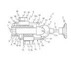
図1は、本発明の一実施形態を示す電動式ステアリング装置の概略構成図である。この電動式ステアリング装置1は、いわゆる首振りチルト方式を採用しており、ステアリングホイール2から延びてステアリングギア(図示せず)に連結されたステアリングシャフト3をその軸の周りに回転可能に保持する三つのステアリングコラム、すなわち、アッパコラム4,ミドルコラム5,ロアコラム6を備えている。そして、各コラム4,5,6の相対位置を適宜調節することによって、ステアリングシャフト3、ひいてはステアリングホイール2が所望の位置に保持される。
Hereinafter, embodiments of the present invention will be described with reference to the drawings.
FIG. 1 is a schematic configuration diagram of an electric steering apparatus showing an embodiment of the present invention. This
アッパコラム4は、内部空間にステアリングシャフト3のユニバーサルジョイント(図示せず)を収容している。アッパコラム4は、ミドルコラム5の後端に形成されたフォーク部51にチルトヒンジピン51aを介してチルト可能に取り付けられている。すなわち、アッパコラム4を、チルトヒンジピン51aを支点として適宜揺動させることにより、ステアリングホイール2のチルト位置を調節することができる。
The
ミドルコラム5は、ロアコラム6に内嵌・保持され、アッパコラム4を支持するフォーク部51と伴に軸線方向に摺動可能になっている。すなわち、車体側に固定されたロアコラム6に対してミドルコラム5を適宜進退させることにより、アッパコラム4がステアリングシャフト3と共にその軸方向に移動し、ステアリングホイール2のテレスコピック位置を調節することができる。
The
アッパコラム4のチルト位置は、電動チルト機構7によって調節される。この電動チルト機構7は、ギアボックス70が付設された例えば3相のブラシレスモータ71と、このブラシレスモータ71に駆動される伸縮ロッド装置72とを備えている。
伸縮ロッド装置72から延びるアクチュエータロッド72aは、ブラシレスモータ71の回転に応じて伸縮する。
The tilt position of the
The
伸縮ロッド装置72の前端部は、ミドルコラム5に固定されたブラケット52にピン53で枢着されており、ヒンジを構成している。アクチュエータロッド72aの後端部は、アッパコラム4に固定されたブラケット42にピン43で枢着されており、ヒンジを構成している。したがって、伸縮ロッド装置72からアクチュエータロッド72aを徐々に繰り出せば、アッパコラム4がミドルコラム5に対して反時計方向に滑らかに回転することになり、ステアリングホイール2を上向きに徐々に傾けることができる。一方、伸縮ロッド装置72中にアクチュエータロッド72aを徐々に収納すれば、アッパコラム4がミドルコラム5に対して時計方向に滑らかに回転することになり、ステアリングホイール2を下向きに徐々に傾けることができる。
A front end portion of the
アッパコラム4のテレスコピック位置は、電動チルトアクチュエータ7とほぼ同一構造の電動テレスコピック機構8によって調節される。すなわち、この電動テレスコピック機構8は、ギアボックス80が付設された例えば3相のブラシレスモータ81と、このブラシレスモータ81に駆動される伸縮ロッド装置82とを備えている。
伸縮ロッド装置82の前端部は、ロアコラム6に固定されたブラケット62にピン63で枢着されており、ヒンジを構成している。アクチュエータロッド82aの後端部は、ミドルコラム5のフォーク部51に固定されたブラケット55にピン56で枢着されており、ヒンジを構成している。したがって、伸縮ロッド装置82からアクチュエータロッド82aを繰り出せば、ミドルコラム5がロアコラム6から繰り出されることになり、ステアリングホイール2を後退させることができる。一方、伸縮ロッド装置82内にアクチュエータロッド82aを収納すれば、ミドルコラム5がロアコラム6に繰り込まれることになり、ステアリングホイール2を前進させることができる。
The telescopic position of the
The front end portion of the telescopic rod device 82 is pivotally attached to a
なお、ミドルコラム5に固定されたブラケット52は、ロアコラム6に形成された溝6aに案内され、ミドルコラム5と共にロアコラム6に対して軸線方向に沿って摺動できるようになっている。
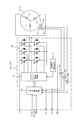
ここで、ブラシレスモータ71及び81は、モータ駆動回路90A及び90Bを内蔵している。これらモータ駆動回路90A及び90Bは、図3に示すように、後述する制御装置100から入力されるスタート及びストップを表す信号ST/SPと、回転方向を指示する回転方向信号CW/CCWと、速度指令を表すパルス幅変調信号PWMと、ブラシレスモータ71及び81のロータ位置を検出する位置検出装置73及び83を構成する例えばホール素子でなる位置検出素子91u〜91wの出力を2値信号に変換するシュミットトリガ回路92u〜92wから入力される回転位置信号とが入力され、これらに基づいてブラシレスモータ71及び81を駆動する三相駆動信号を形成する三相分配回路93と、この三相分配回路93から出力される三相駆動信号と、後述するインバータ回路96の過電流を検出する過電流検出回路94からの過電流検出値信号SIとが入力されてインバータ回路96を構成する電界効果トランジスタQua〜Qwbのゲートを駆動するFETゲート駆動回路95と、一対の電界効果トランジスタ(FET)Qua,Qub、Qva,Qvb及びQwa,Qwbを直列に接続してブラシレスモータ71及び81の各相コイルLu、Lv及びLwに対応する3組のFET回路を並列に接続したインバータ回路96とを備えている。ここで、FETゲート駆動回路95は、過電流検出回路94から正常モータ電流状態を表す例えば論理値“0”の過電流検出信号SIが入力されているときには、三相分配回路93から入力される三相駆動信号に応じた回転方向及び回転速度ブラシレスモータ71及び81を駆動するようにインバータ回路96の各電界効果トランジスタQua〜Qwbのゲートにパルス幅変調信号PWMを供給するが、過電流検出回路94から過電流状態を表す例えば論理値“1”の過電流検出信号SIが入力されたときに、例えばインバータ回路96の下アームを構成する電界効果トランジスタQub、Qvb及びQwbのゲートに供給するPWM信号のデューティ比を0%に制御してブラシレスモータ71又は81の励磁コイルLu〜Lwへの通電を停止させる。
The
Here, the
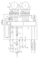
そして、モータ駆動回路90A及び90Bが制御装置100によって駆動制御される。この制御装置100は、図2に示すように、車両に搭載されたバッテリ101からのバッテリ電圧Vbがヒューズ102を介して入力されるレギュレータ103と、車両に搭載した走行状態検出手段としての車速センサ104の車速検出値を通信回線を介して他の制御系から取得する通信インタフェース105と、レギュレータ103から出力される電源電圧Vcによって作動される演算処理装置(CPU)106と、この演算処理装置106に接続された不揮発性メモリ107と、前記ヒューズ102とモータ駆動回路90A及び90Bのバッテリ電圧入力端との間に制御装置100内で介挿されたスイッチング部としてのリレー回路108とを備えている。
The
演算処理装置105には、バッテリ電圧VBが直接入力されると共には、レギュレータ103の電源電圧が入力され、さらにバッテリ101にヒューズ110を介して接続されたイグニッションスイッチ111から出力されるイグニッション信号IGと、バッテリ101にヒューズ112を介して接続されたキースイッチ113から出力されるキースイッチ信号KSと、乗降ドアの開閉状態を示すドアスイッチ114のドア信号DSと、チルト機構7の傾斜角を指示するマニュアルチルトスイッチ部115及びテレスコピック機構8の伸縮位置を指示するテレスコスイッチ部116のスイッチ信号ST1及びST2と、モータ駆動回路90A及び90Bから出力される120度の位相差を有する位置検出信号FG1及びFG2とが入力されている。
The
そして、演算処理装置106は、レギュレータ103から制御電源Vcが入力されたときに、モータ制御処理を実行する。
このモータ制御処理は、レギュレータ103から制御電圧Vcが供給開始されたときに実行開始され、先ず、ステップS1で、リレー回路108のリレーコイルLLRと接地との間に接続したスイッチング素子120をオン状態に制御する高レベルのリレー制御信号SLをスイッチング素子120に出力してからステップS2に移行する。
The
The motor control process, the control voltage Vc from the
このステップS2では、モータ駆動回路90A及び90Bが異常であるか否かを判定し、モータ駆動回路90A及び90Bが異常であるときにはステップS3に移行して、低レベルのリレー制御信号SLをスイッチング素子120に出力して、スイッチング素子120をオフ状態に制御してから処理を終了し、モータ駆動回路90A及び90Bが正常であるときにはステップS4に移行する。
In step S2, it is determined whether or not the
このステップS4では、チルト機構7のモータ駆動回路90Aを作動させてチルト機構7を上側のメカニカルストッパ(図示せず)に当接する上死点方向に駆動してメカニカルストッパに当接したことを検出したときに、この位置から所定量下側に戻した電動チルト制御範囲の退避側の制御開始位置を設定すると共に、この退避側の制御開始位置から所定ストーク量を加えて電動チルト制御範囲の他方の制御開始位置を設定してからステップS5に移行する。
In this step S4, the
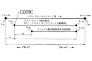
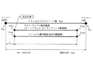
すなわち、電動チルト制御範囲は、図6に示すように、退避側となるチルトアップ側のメカニカルストッパ位置PMUとチルトダウン側のメカニカルストッパ位置PMDとで決定されるチルト機構の最大移動範囲RMAXに対してメカニカルストッパ位置PMUから内側に所定距離LUとった位置を電動チルト制御範囲RCの退避側制御開始位置PTIS1として設定し、この位置を記憶装置107の電動チルト制御範囲記憶領域に記憶すると共に、この退避側制御開始位置PTIS1から電動チルト制御範囲RCを採った位置を電動チルト制御範囲RCの下側制御開始位置PTIS2として設定し、これを同様に記憶装置107の電動チルト制御範囲記憶領域に記憶する。
That is, electric tilt control range, as shown in FIG. 6, the maximum movement range of the tilt mechanism to be determined by the mechanical stopper position P MD of the retreat side becomes the mechanical stopper position of the tilt-up side P MU and tilt-down side R the position taken predetermined distance L U inwardly from the mechanical stopper position P MU set as the save-side control start position P TIS1 the electric tilt control range R C against MAX, electric tilt control range storage of the
なお、チルト機構7のマニュアルチルトスイッチ部115を操作して設定可能なマニュアルチルト動作範囲は、電動チルト制御範囲RCの退避側制御開始位置PTIS1からダウン方向に所定距離LMだけ移動させた位置PM1と電動チルト制御範囲の下側制御開始位置PTIS2と等しい下側制御開始位置PM2とで規定されている。
ここで、制御開始位置を設定するには、図8に示す制御開始位置設定処理を実行する。この制御開始位置設定処理は、先ず、ステップS61で、モータ駆動回路90Aに対して最小駆動速度VMINとなる最小デューティ比の速度指令PWMとチルトアップ側に移動させる例えば正転方向指令CWを出力し、次いでステップS62に移行して、モータ駆動回路90Aから入力される位置検出信号FG1及びFG2の何れか1つのパルスの立ち上がり時点から次のパルスの立ち上がり時点までの時間を計測するか又は単位時間当たりのパルス数を計測することにより駆動速度VTIを算出してからステップS63に移行する。
Incidentally, the manual tilt switch unit 115 to be set by operating a manual tilt operation range of the
Here, in order to set the control start position, the control start position setting process shown in FIG. 8 is executed. In this control start position setting process, first, in step S61, the
このステップS63では、駆動速度VTIが最小駆動速度VMINより小さい閾値VTIt以下であるか否かを判定し、VTI>VTItであるときにはメカニカルストッパに当接していないものと判断してVTI≦VTItとなるまで待機し、VTI≦VTItであるときにはメカニカルストッパに当接したものと判断してステップS64に移行する。
このステップS64では、モータ駆動回路90Aに対して最小駆動速度VMINよりは速いが比較的低い所定速度の速度指令PWMを出力すると共に、逆転方向指令CCWを出力し、次いでステップS65に移行して、位置検出信号FG1又はFG2のパルス数Npを計数し、次いでステップS66に移行して、計数したパルス数Npが予め設定した設定値Npsに達したか否かを判定し、Np<Npsであるときには前記ステップS65に戻り、Np=NpsとなったときにステップS67に移行する。
In this step S63, it is determined whether or not the drive speed V TI is equal to or less than a threshold value V TIt that is smaller than the minimum drive speed V MIN , and if V TI > V TIt, it is determined that it is not in contact with the mechanical stopper. The process waits until V TI ≦ V TIt, and if V TI ≦ V TIt, it is determined that it is in contact with the mechanical stopper, and the process proceeds to step S64.
In this step S64, a speed command PWM of a predetermined speed which is faster than the minimum drive speed V MIN but relatively low is outputted to the
このステップS67では、モータ駆動回路90Aに対する速度指令PWM及び回転方向指令CCWの出力を停止して、現在位置を電動チルト制御範囲の退避側制御開始位置として設定し、このときの下記図9で計数される位置計数値Pnを制御原点を表す“0”に設定してから処理を終了する。
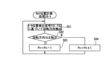
また、演算処理装置106では、図9に示すチルト位置計測処理を実行する。このチルト位置計測処理は、先ず、ステップS81で後述するようにモータ位置検出信号FG1及びFG2に基づいてブラシレスモータ71の回転方向を検出し、次いでステップS82に移行して、回転方向が正転方向であるか否かを判定し、正転方向であるときにはステップS83に移行して、モータ位置検出信号FG1が立ち上がる毎に位置計測値Pnをデクリメントしてから前記ステップS81に戻り、逆転方向であるときにはステップS84に移行してモータ位置検出信号FG2が立ち上がる毎に位置計測値Pnをインクリメントしてから前記ステップS81に戻る。
In this step S67, the output of the speed command PWM and the rotation direction command CCW to the
Further, the
図4のモータ制御処理に戻って、ステップS5では、テレスコピック機構8のモータ駆動回路90Bを作動させてテレスコピック機構8を縮み側のメカニカルストッパ(図示せず)に当接する下死点方向に駆動してメカニカルストッパに当接したことを検出したときに、この位置から所定量伸び側に戻した電動テレスコピック制御範囲の退避側となる縮み側制御開始位置PTES1を設定し、この退避側制御開始位置PTES1に所定ストローク量を加算した位置を反対側の伸び側制御開始位置PTES2を設定してからステップS6に移行する。
Returning to the motor control processing of FIG. 4, in step S5, the
すなわち、電動テレスコ制御範囲は、図7に示すように、退避側となる縮み側のメカニカルストッパ位置PMSと伸び側のメカニカルストッパ位置PMLとで決定されるチルト機構の最大移動範囲RMAXに対してメカニカルストッパ位置PMUから内側に所定距離LSとった位置を電動テレスコ制御範囲RTEの伸び側制御開始位置PTES1として設定し、この位置を記憶装置107の電動テレスコ制御範囲記憶領域に記憶すると共に、この縮み側制御開始位置PTES1から電動チルト制御範囲RTEを採った位置を電動テレスコ制御範囲RTEの伸び側制御開始位置PTES2として設定し、これを同様に記憶装置107の電動チルト制御範囲記憶領域に記憶する。
That is, as shown in FIG. 7, the electric telescopic control range is the maximum movement range R MAX of the tilt mechanism determined by the retracted mechanical stopper position PMS and the extended mechanical stopper position PML. the position taken predetermined distance L S inward from the mechanical stopper position P MU set as the extension side control start position P TES1 of the electric telescopic control range R TE, the position the electric telescopic control range storage area of the
なお、テレスコピック機構8のマニュアルチルトスイッチ部116を操作して設定可能なマニュアルテレスコ動作範囲は、電動テレスコ制御範囲RTEの縮み側制御開始位置PTES1及び伸び側制御開始位置PTES2と同一の縮み側動作開始位置PTEM1及び伸び側動作開始位置PTEM2に設定されている。
このテレスコピック機構8でも図示しないが図8と同様の電動テレスコ範囲設定処理を実行する。
The manual telescopic operation range that can be set by operating the manual tilt switch 116 of the telescopic mechanism 8 is the same as the contraction side control start position P TES1 and the extension side control start position P TES2 of the electric telescopic control range R TE. The side operation start position P TEM1 and the extension side operation start position P TEM2 are set.
The telescopic mechanism 8 executes the electric telescopic range setting process similar to that shown in FIG.
ステップS6では、イグニッションスイッチ111のスイッチ信号IGを読込み、次いでステップS7に移行して、エンジン始動時でイグニッション信号IGがオン状態であるか否かを判定し、エンジン始動時ではなくイグニッションスイッチ111がオフ状態であるときには、ステップS8に移行して、低レベルのリレー制御信号SLをスイッチング素子120に出力してから前記ステップS6に戻り、エンジン始動時であってイグニッションスイッチ111がオン状態であるときにはステップS9に移行して、高レベルのリレー制御信号SLをスイッチング素子120に出力してからステップS10に移行する。
In step S6, the switch signal IG of the
このステップS10では、エンジン始動回数Nを“1”だけインクリメントしてからステップS11に移行し、エンジン始動回数Nが予め設定した設定値Nsに達したから否かを判定し、N≧Nsであるときには、エンジン始動開始数Nが設定値Nsに達して制御原点補正が必要であるものと判断してステップS12に移行し、エンジン始動回数Nを“0”にリセットしてから前記ステップS4に戻り、N<Nsであるときには制御原点補正はまだ必要ないものと判断してステップS13に移行する。 In this step S10, the engine start frequency N is incremented by “1”, and then the process proceeds to step S11, where it is determined whether or not the engine start frequency N has reached a preset set value Ns, and N ≧ Ns. In some cases, the engine start start number N reaches the set value Ns and it is determined that the control origin correction is necessary, the process proceeds to step S12, the engine start number N is reset to “0”, and then the process returns to step S4. When N <Ns, it is determined that the control origin correction is not necessary yet, and the process proceeds to step S13.
このステップS13では、記憶装置107のチルト位置記憶領域にチルト位置が記憶されているか否かを判定し、チルト位置が記憶されていないときにはステップS14に移行して、チルト機構7をマニュアル動作範囲のチルトアップ側動作開始位置PTIM1まで下降させるように所定の速度指令PWM及び逆転方向指令CCWを出力し、位置計測値Pnがチルトアップ側動作開始位置PTIM1に相当する計数値Pn1に達したときに速度指令PWM及び逆転方向指令CCWの出力を停止させて、チルト機構7をマニュアル動作範囲のチルトアップ側動作開始位置PTIM1まで下降させてからステップS16に移行する。
In this step S13, it is determined whether or not the tilt position is stored in the tilt position storage area of the
一方、ステップS13の判定結果が、チルト位置が記憶されているときにはステップS15に移行して、モータ駆動回路90Bに所定の速度指令PWMを出力すると共に、逆転方向指令CCWを出力して、ブラシレスモータ81を逆転させ、位置計数値Pnが記憶されているチルト位置に相当する設定値Pn2に達したときに、速度指令PWM及び逆転方向指令CCWの出力を停止して、チルト機構7を記憶されたチルト位置まで下降させてからステップS16に移行する。
On the other hand, if the determination result of step S13 is that the tilt position is stored, the process proceeds to step S15, where a predetermined speed command PWM is output to the
このステップS16では、テレスコ位置が記憶装置107のテレスコ位置記憶領域に記憶されているか否かを判定し、テレスコ位置が記憶されているときにはステップS17に移行して、モータ駆動回路90Bに逆転方向指令CCWと所定の速度指令PWMを出力し、位置計測値Pnが記憶されたテレスコ位置に相当する設定値Pn3に達したときに、逆転方向指令CCWと速度指令PWMの出力を停止して、記憶されたテレスコ位置までテレスコピック機構8を伸張させてからステップS18に移行し、テレスコ位置が記憶されていないときには直接ステップS18に移行する。
In this step S16, it is determined whether or not the telescopic position is stored in the telescopic position storage area of the
ステップS18では、マニュアルチルトスイッチ部115からチルト位置を指定するスイッチ信号ST1が入力されたか否かを判定し、スイッチ信号ST1が入力されたときには、ステップS19に移行して、入力されたスイッチ信号ST1に応じたチルト位置にチルト機構7を制御してからステップS20に移行し、スイッチ信号ST1が入力されていないときには、直接ステップS20に移行する。
In step S18, it is determined whether or not a switch signal ST1 for designating a tilt position is input from the manual tilt switch unit 115. When the switch signal ST1 is input, the process proceeds to step S19 to input the input switch signal ST1. After the
このステップS20では、マニュアルテレスコスイッチ部116からテレスコ位置を指定するスイッチ信号ST2が入力されたか否かを判定し、スイッチ信号ST2が入力されているときにはステップS21に移行して、入力されたスイッチ信号ST2に応じたテレスコ位置にテレスコピック機構8を制御してからステップS22に移行し、スイッチ信号ST2が入力されていないときには直接ステップS22に移行する。 In step S20, it is determined whether or not a switch signal ST2 for designating a telescopic position is input from the manual telescopic switch unit 116. When the switch signal ST2 is input, the process proceeds to step S21, and the input switch signal is input. After the telescopic mechanism 8 is controlled to the telescopic position corresponding to ST2, the process proceeds to step S22. When the switch signal ST2 is not input, the process directly proceeds to step S22.
このステップS22では、前回のスイッチ信号ST1又はST2が入力されてから所定時間T1が経過したか否かを判定し、所定時間T1が経過したときには後述するステップS27に移行し、所定時間T1が経過していないときには、ステップS23に移行して、車速センサ104で検出した車速検出値Vsを読込み、次いでステップS24に移行して、車速検出値Vsが車両が走行状態であると判断可能な閾値Vst以上であるか否かを判定し、Vs≧Vstであるときには後述するステップS27に移行し、Vs<Vstであるときには車両が停止状態にあるものと判断してステップS25に移行する。
In this step S22, it is determined whether or not a predetermined time T1 has elapsed since the previous switch signal ST1 or ST2 was input. When the predetermined time T1 has elapsed, the process proceeds to step S27 described later, and the predetermined time T1 has elapsed. If not, the process proceeds to step S23, the vehicle speed detection value Vs detected by the
このステップS25では、異常判定フラグFAが異常を表す“1”に設定されているか否かを判定し、FA=“1”であるとき即ち異常状態が発生しているときにはステップS26に移行して、リレー回路108をオフ状態とする低レベルのリレー制御信号SLをリレーコイルLLと接地との間に介挿されたスイッチング素子120に出力して、このスイッチング素子120をオフ状態に制御してからモータ制御処理を終了する。
In this step S25, it is determined whether or not the abnormality determination flag FA is set to “1” indicating an abnormality. When FA = “1”, that is, when an abnormal state occurs, the process proceeds to step S26. The low level relay control signal SL for turning off the
一方、ステップS25の判定結果が、FA=“0”であるとき即ち異常状態が発生していない正常状態であるときには前記ステップS18に戻る。
ステップS27では、前記ステップS26と同様にリレー回路108をオフ状態とする低レベルのリレー制御信号SLをリレーコイルLLRと接地との間に介挿されたスイッチング素子120に出力して、このスイッチング素子120をオフ状態に制御してからステップS28に移行する。
On the other hand, when the determination result in step S25 is FA = “0”, that is, in a normal state where no abnormal state has occurred, the process returns to step S18.
In step S27, a low-level relay control signal SL for turning off the
このステップS28では、キースイッチ113から出力されるキースイッチ信号KSを読込み、次いでステップS29に移行して、キースイッチ信号KSがオフ状態即ち運転者が後者する可能性がある状態であるか否かを判定し、キースイッチ信号KSがオン状態を継続しているときには運転者が後者の可能性が略ないものと判断してキースイッチ信号KSがオフ状態となるまで待機し、キースイッチ信号KSがオフ状態となるとステップS30に移行する。
In this step S28, the key switch signal KS output from the
このステップS30では、後述する異常検出処理で異常判定フラグFAが“1”にセットされているか否かを判定し、これが“1”にセットされているときにはそのままモータ制御処理を終了し、異常判定フラグFAが“0”にリセットされているときにはステップS31に移行する。
このステップS31では、前述したステップS1と同様に、リレー回路108のリレーコイルLLRと接地との間に接続したスイッチング素子120をオン状態に制御する高レベルのリレー制御信号SLをスイッチング素子120に出力してからステップS32に移行する。
In this step S30, it is determined whether or not an abnormality determination flag FA is set to “1” in an abnormality detection process to be described later. When this flag is set to “1”, the motor control process is terminated as it is, and an abnormality determination is made. When the flag FA is reset to “0”, the process proceeds to step S31.
In step S31, similar to step S1 described above, a high level relay control signal SL for controlling the
このステップS32では、現在のチルト位置は記憶装置107のチルト位置記憶領域に記憶されているチルト位置と一致するか否かを判定し、両者が一致しないときには、ステップS33に移行して、現在のチルト位置をチルト位置記憶領域に更新記憶してからステップS34に移行し、両者が一致するときには直接ステップS34に移行する。
このステップS34では、現在のテレスコ位置は記憶装置107のテレスコ位置記憶領域に記憶されているテレスコ位置と一致するか否かを判定し、両者が一致しない場合には、ステップS35に移行して、現在のテレスコ子位置を記憶装置107のテレスコ位置記憶領域に更新記憶してからステップS36に移行し、両者が一致する場合には、そのままステップS36に移行する。
In this step S32, it is determined whether or not the current tilt position matches the tilt position stored in the tilt position storage area of the
In this step S34, it is determined whether or not the current telescopic position matches the telescopic position stored in the telescopic position storage area of the
このステップS36では、チルト機構7を自動制御する場合の上側退避位置に移動制御させてからステップS37に移行し、テレスコピック機構8を縮み側退避位置に移動制御してから前記ステップS6に戻る。
また、演算処理装置106では、図5に示す異常検出処理を所定時間(例えば10msec)毎のタイマ割込処理として実行する。この異常検出処理は、先ず、ステップS41で、モータ駆動回路90Aから出力されるモータ位置検出信号FG1,FG2を読込み、次いでステップS42に移行して、モータ駆動回路90Aに対する速度指令値PWMが“0”であるか否かを判定し、速度指令値PWMが“0”であるときにはステップS43に移行して、モータ駆動回路90Aから出力されるモータ位置検出信号FG1及びFG2の少なくとも一方に状態変化が生じたか否かを判定し、状態変化を生じたときには速度指令値PWMが“0”であり、モータ駆動回路90Aが駆動されていないにもかかわらずブラシレスモータ71が回転駆動しており、モータ駆動回路90Aに天絡等の異常が発生したものと判断してステップS44に移行して、異常判定フラグFAを“1”にセットし、状態変化を生じないときにはモータ駆動回路90Aが正常であるものと判断して後述するステップS49に移行する。
In step S36, the movement to the upper retracted position in the case of automatically controlling the
Further, the
一方、ステップS42の判定結果が、速度指令値PWMが“0”以外であるときにはステップS45に移行して、所定時間内にモータ位置検出信号FG1及びFG2が状態変化しているか否かを判定し、これらが状態変化していないときには、ブラシレスモータ71が回転していない異常状態であるものと判断して前記ステップS44に移行し、モータ位置検出信号FG1及びFG2が状態変化しているときには一応ブラシレスモータ71が正常であるものと判断してステップS46に移行する。
On the other hand, when the determination result of step S42 is that the speed command value PWM is other than “0”, the process proceeds to step S45, where it is determined whether or not the motor position detection signals FG1 and FG2 have changed their state within a predetermined time. When these are not changed, it is determined that the
このステップS46では、モータ駆動回路90Aに対する回転方向指令CW/CCWを読込み、次いでステップS47に移行して、モータ駆動回路90Aから入力されるモータ位置検出信号FG1及びFG2を読込み、両信号FG1及びFG2の立ち上がりの順序から回転方向を検出する。すなわち、位置検出信号FG1及びFG2は、例えばブラシレスモータ71が正転しているときには、図10に示すように、例えば位置検出信号FG1に対して位置検出信号FG2が電気角で120度進んだ位相進み状態となり、逆にブラシレスモータ71が逆転しているときには、図11に示すように、例えば位置検出信号FG1に対して位置検出信号FG2が電気角で120度遅れた位相遅れ状態となる。このため、位置検出信号FG2の立ち上がり時点から立ち下がり時点までの間位置検出信号FG1の立ち上がり時点がきたときには正転方向と判断し、逆に位置検出信号FG1の立ち上がり時点から立ち下がり時点までの間に位置検出信号FG2の立ち上がり時点が来たときには逆転方向と判断することができる。
In this step S46, the rotation direction command CW / CCW for the
次いで、ステップS48に移行して、回転方向指令CW/CCWとステップS47で検出した回転方向検出値とが一致するか否かを判定し、両者が不一致であるときにはモータ駆動回路90Aが異常であると判断して前記ステップS44に移行し、両者が一致する場合にはモータ駆動回路90Aが正常であるものと判断してステップS49に移行する。
Next, the process proceeds to step S48, where it is determined whether or not the rotation direction command CW / CCW matches the rotation direction detection value detected in step S47. If they do not match, the
このステップS49では、モータ駆動回路90Bから出力されるモータ位置検出信号FG1,FG2を読込み、次いでステップS50に移行して、モータ駆動回路90Bに対する速度指令値PWMが“0”であるか否かを判定し、速度指令値PWMが“0”であるときにはステップS51に移行して、モータ駆動回路90Bから出力されるモータ位置検出信号FG1及びFG2の少なくとも一方に状態変化が生じたか否かを判定し、状態変化を生じたときには速度指令値PWMが“0”であり、モータ駆動回路90Bが駆動されていないにもかかわらずブラシレスモータ81が回転駆動しており、モータ駆動回路90Bに天絡等の異常が発生したものと判断してステップS52に移行して、異常判定フラグFAを“1”にセットし、状態変化を生じないときにはモータ駆動回路90Bが正常であるものと判断してC57に移行し、異常判定フラグFAを“0”にリセットしてからタイマ割込処理を終了して所定のメインプログラムに復帰する。
In step S49, the motor position detection signals FG1 and FG2 output from the
一方、ステップS50の判定結果が、速度指令値PWMが“0”以外であるときにはステップS53に移行して、所定時間内にモータ位置検出信号FG1及びFG2が状態変化しているか否かを判定し、これらが状態変化していないときには、ブラシレスモータ81が回転していない異常状態であるものと判断して前記ステップS52に移行し、モータ位置検出信号FG1及びFG2が状態変化しているときには一応ブラシレスモータ81が正常であるものと判断してステップS54に移行する。
On the other hand, when the determination result in step S50 is that the speed command value PWM is other than “0”, the process proceeds to step S53, where it is determined whether or not the motor position detection signals FG1 and FG2 have changed their state within a predetermined time. When these are not changed, it is determined that the
このステップS54では、モータ駆動回路90Bに対する回転方向指令CW/CCWを読込み、次いでステップS55に移行して、前述したステップS47と同様にモータ駆動回路90Bから入力されるモータ位置検出信号FG1及びFG2を読込み、両信号FG1及びFG2の立ち上がりの順序からモータ回転方向を検出する。
次いで、ステップS56に移行して、回転方向指令CW/CCWとステップS55で検出した回転方向検出値とが一致するか否かを判定し、両者が不一致であるときにはモータ駆動回路90Bが異常であると判断して前記ステップS52に移行し、両者が一致する場合にはモータ駆動回路90Bが正常であるものと判断して前記ステップS57に移行する。
In this step S54, the rotational direction command CW / CCW for the
Next, the process proceeds to step S56, where it is determined whether or not the rotation direction command CW / CCW matches the rotation direction detection value detected in step S55. If the two do not match, the
この図4、図5、図8及び図9の処理において、図4の処理におけるS1,S4〜S22,S25〜S35の処理が制御部に対応し、図5の処理におけるステップS46,S47,S54及びS55の処理がモータ回転方向検出部に対応し、ステップS44、S48、S52及びS55の処理と図4のステップS2,S3,S23,S24の処理が異常停止部に対応し、図8のステップS61の処理が最小駆動制御手段に対応し、ステップS62及びS63の処理が上死点位置検出手段に対応し、ステップS64〜S67の処理が制御開始位置設定手段に対応している。 4, S1, S4 to S22, and S25 to S35 in the process of FIG. 4 correspond to the control unit, and steps S46, S47, and S54 in the process of FIG. And S55 correspond to the motor rotation direction detector, and the processes of steps S44, S48, S52, and S55 and steps S2, S3, S23, and S24 of FIG. 4 correspond to the abnormal stop unit. The process of S61 corresponds to the minimum drive control means, the processes of steps S62 and S63 correspond to the top dead center position detection means, and the processes of steps S64 to S67 correspond to the control start position setting means.
次に、上記実施形態の動作を説明する。
今、生産工場で車両にチルト機構7及びテレスコピック機構8が組み付けられると共に、バッテリ101が搭載されて、このバッテリ101から制御装置100にバッテリ電圧VBが投入されると、レギュレータ103から制御電圧Vcが演算処理装置106に供給されることにより、この演算処理装置106で図4のモータ制御処理及び図5の異常検出処理が実行開始される。
Next, the operation of the above embodiment will be described.
Now, when the
このとき、モータ駆動回路90A及び90Bに異常が発生しておらず、図5の異常検出処理で異常判定フラグFAが“0”にリセットされているものとする。
このため、図4のモータ制御処理では、ステップS1で、高レベルのリレー制御信号SLをスイッチング素子120に出力することにより、リレーコイルLLRに通電してリレー接点tLRをオン状態とすることにより、ブラシレスモータ71及び81のモータ駆動回路90A及び90Bにバッテリ電圧VBを供給開始する。
そして、異常判定フラグFAが“0”にリセットされているので、ステップS2からステップS4に移行して、チルト機構7の制御開始位置を設定する制御開始位置設定処理を行う。
At this time, it is assumed that no abnormality has occurred in the
Therefore, the motor control process shown in FIG. 4, at step S1, by outputting a relay control signal SL of high level to the
Since the abnormality determination flag FA has been reset to “0”, the process proceeds from step S2 to step S4, and a control start position setting process for setting the control start position of the
この制御開始位置設定処理では、先ず、チルト機構7のモータ駆動回路90Aに対して、チルト機構7を最小駆動速度VMINで傾動させる最小デューティ比の速度指令PWMとチルトアップ側に傾動させる例えば正転方向指令CWを出力することにより、ステアリングシャフト3を徐々に上方に緩やかに傾動させる。このとき、モータ位置検出信号FG1又はFG2に基づいて移動速度VTIを算出し、この移動速度VTIが最小駆動速度VMINより小さい閾値VTIt以下となったか否かを判定し、移動速度VTIがVTI>VTItであるときにはステアリングシャフト3がメカニカルストッパに当接することなく傾動を継続しているものと判断して待機する。
In this control start position setting process, first, the
その後、ステアリングシャフト3がメカニカルストッパに当接する状態となると、ステアリングシャフト3のチルトアップ方向への移動が規制されることにより、移動速度VTIが低下し、これが閾値VTIt以下となると、メカニカルストッパに当接したものと判断されて比較的低い所定速度の速度指令PWMを出力すると共に、逆転方向指令CCWを出力することにより、ステアリングシャフト3の下降を開始させる。
Thereafter, when the
このときの、位置検出信号FG1又はFG2のパルス数Npを計測し、計測したパルス数Npが電動チルト制御範囲の退避側制御開始位置を決定する所定移動量LUに相当するパルス数Npsに達したらモータ駆動回路90Aに対する速度指令PWM及び逆転方向しれCCWの出力を停止して、ステアリングシャフト3を電動チルト制御範囲の退避側制御開始位置に停止させる。このときの位置計数値Pnuを“0”に設定し、これ記憶装置107の電動チルト制御範囲記憶領域に記憶する。
また、設定した位置計数値Pnuに電動チルト制御範囲のストロークに相当するパルス数を加算してチルトダウン側の位置計数値Pndを算出し、この位置計数値Pndを記憶装置107の電動チルト制御範囲記憶領域に記憶する。
At this time, the number of pulses Np of the position detection signal FG1 or FG2 is measured, and the measured number of pulses Np reaches the number of pulses Nps corresponding to a predetermined movement amount L U that determines the retreat-side control start position of the electric tilt control range. Then, the output of the speed command PWM and the reverse rotation direction CCW to the
Further, the position count value Pnd on the tilt down side is calculated by adding the number of pulses corresponding to the stroke of the electric tilt control range to the set position count value Pnu, and this position count value Pnd is calculated as the electric tilt control range of the
次いで、ステップS5に移行してテレスコピック機構8についても同様に最小駆動速度でミドルコラム5を縮み方向に収縮させ、メカニカルストッパに当接して駆動速度が閾値より低下したときに、メカニカルストッパへの当接を検出し、次いでモータ駆動回路90Bに逆転方向指令CCWを出力すると共に、比較的低速度の速度指令PWMを出力してミドルコラム5を、電動テレスコ制御範囲の縮み側制御開始位置PTES1まで伸張させる。そして、この縮み側制御開始位置PTES1で計数値Pnsを“0”に設定し、これを記憶装置107の電動テレスコ制御範囲記憶領域に記憶すると共に、計数値Pnsに電動テレスコ制御範囲のストロークに相当するモータ位置検出信号FG1又はFG2のパルス数を加算して伸び側の位置計数値Pnlを算出し、この位置計数値Pnlを記憶装置107の電動テレスコ制御範囲記憶領域に記憶してから処理を終了する。
Next, the process proceeds to step S5, and when the telescopic mechanism 8 similarly contracts the
このため、チルト機構7では、ステアリングシャフト3が上方側の退避位置となってステアリングホイール2が上方に退避した状態となり、さらにテレスコピック機構8では、ミドルコラム5がロアコラム6に対して収縮した状態となって、ステアリングホイール2が運転者の乗降を容易にするように上前方に退避した状態となる。
このように、チルト機構7の電動チルト制御範囲及びテレスコピック機構8の電動テレスコ制御範囲を設定する場合に、ブラシレスモータ71及び81を最小駆動速度VMINで駆動しながらメカニカルストッパ側に正転駆動し、このときの移動速度が閾値以下に低下したときにメカニカルストッパに当接したものと判断し、ブラシレスモータ71及び81をチルト機構7の電動チルト制御範囲の退避側制御開始位置及びテレスコピック機構8の電動テレスコ制御範囲の退避側制御開始位置に移動させて、これら退避側制御開始位置を設定するので、チルト機構7及びテレスコピック機構8がメカニカルストッパに衝接することを確実に防止することができ、送りねじの噛み込みや機構系の破損を確実に防止することができる。しかも、メカニカルストッパへの当接をモータ駆動回路90A及び90Bから入力されるモータ位置検出信号FG1及びFG2に基づいて駆動速度を算出し、この駆動速度が閾値以下に減少したことを検出することにより、検出するようにしているので、別途速度検出手段を設ける必要がなく、部品点数を減少させて、全体の構成を簡易小型化することができる。
Therefore, in the
As described above, when the electric tilt control range of the
そして、電動チルト制御範囲及び電動テレスコ制御範囲が設定されると、これら制御範囲の制御開始位置PTIS1及びPTIS2とPTES1及びPTES2との内側に夫々減速開始位置を設定し、この減速開始位置に達したときにブラシレスモータ71及び81の速度指令PWMを漸減させて減速制御を行うことにより、制御開始位置PTIS1及びPTIS2とPTES1及びPTES2での停止を、オーバーランを伴うことなく確実に行うことができる。
When the electric tilt control range and the electric telescopic control range are set, the deceleration start position is set inside the control start positions P TIS1 and P TIS2 and P TES1 and P TES2 of these control ranges, and this deceleration start is set. When the position is reached, the speed command PWM of the
また、上記図8の制御開始位置設定処理は、演算処理装置106に電源が投入された場合だけでなく、イグニッションスイッチ111がオン状態となるエンジン始動回数Nが所定値Ns以上となったときにも繰り返し実行され、制御原点が狂うことを防止している。
以上のように制御開始位置設定処理が終了すると、このときのイグニッションスイッチ111がオフ状態であるものとすると、ステップS6からステップS7を経てステップS8に移行し、低レベルのリレー制御信号SLをスイッチング素子120に出力することにより、スイッチング素子120をオフ状態とし、これによってリレー回路108をオフ状態としてブラシレスモータ71及び81のモータ駆動回路90A及び90Bへのバッテリ電圧VBの供給を停止し、ステップS6〜S8を繰り返すループ処理状態となる。
Further, the control start position setting process of FIG. 8 is performed not only when the
When the control start position setting process is completed as described above, assuming that the
その後、工場出荷状態となるか又はユーザが車両を使用する状態となって、運転者が乗車してイグニッションスイッチ111をオン状態としてエンジンを始動すると、図4の処理で、ステップS7からステップS9に移行して、高レベルのリレー制御信号SLがスイッチング素子120に出力されることにより、リレー回路108がオン状態に制御されてブラシレスモータ71及び81のモータ駆動回路90A及び90Bにバッテリ電圧VBが供給されて作動可能な状態となる。
Thereafter, when the vehicle is shipped from the factory or the user is in a state of using the vehicle and the driver gets on and starts the engine with the
このとき、エンジン始動回数Nがインクリメントされ、このエンジン始動回数Nが設定値Nsに達していないときにはステップS11からステップS13に移行して、先ずチルト機構7のチルト位置が記憶装置107のチルト位置記憶領域に記憶されているか否かを判定する。車両がユーザに納車されたばかりであるときには、記憶装置107のチルト位置記憶領域及びテレスコ位置記憶領域にはチルト位置及びテレスコ位置が記憶されていない状態となるので、ステップS13からステップS14に移行して、チルト機構7のブラシレスモータ71を駆動する逆転方向指令CCW及び所定パルス数のチルト位置指令PWMを出力してブラシレスモータ71を回転駆動させて、チルト機構7のステアリングシャフト3をマニュアル動作範囲の最上位点まで下降させる。これによって、ステアリングホイール2が運転者の操作可能範囲内に下降する。
At this time, the engine start count N is incremented, and when the engine start count N has not reached the set value Ns, the routine proceeds from step S11 to step S13, and the tilt position of the
一方、テレスコピック機構8については、もともと制御原点がミドルコラム5の収縮範囲の最縮み側に設定されているので、ステップS16からステップS18にジャンプすることからブラシレスモータ81を駆動することなく停止状態を維持する。
その後、運転者がチルト位置を調整したい場合には、マニュアルチルトスイッチ部ST1で好みのチルト位置を選択し、これに応じたスイッチ信号ST1が入力されると、入力されたスイッチ信号ST1に応じて逆転方向指令CCW及び速度指令PWMがモータ駆動回路90Aに出力されて、ブラシレスモータ71が例えば逆転されてステアリングホイール2が運転者の所望チルト位置まで下降される。
On the other hand, for the telescopic mechanism 8, the control origin is originally set to the most contracted side of the contraction range of the
Thereafter, when the driver wants to adjust the tilt position, the user selects a desired tilt position with the manual tilt switch section ST1, and when a switch signal ST1 corresponding to the selected tilt position is input, according to the input switch signal ST1. The reverse direction command CCW and the speed command PWM are output to the
同様に、運手者がテレスコ位置を調整した場合には、マニュアルテレスコスイッチ部116を操作して好みのテレスコ位置を選択し、これに応じたスイッチ信号ST2が入力されると、入力されたスイッチ信号ST2に応じて逆転方向指令CCW及び速度指令PWMがモータ駆動回路90Bに出力されて、ブラシレスモータ81が例えば逆転されてステアリングホイール2が運転者の所望テレスコ位置まで伸張される。
このように、運転者がマニュアルチルトスイッチ部115及びマニュアルテレスコスイッチ部116を操作することにより、ステアリングホイール2を運転者の所望位置に移動させることができる。
Similarly, when the operator adjusts the telescopic position, the user selects the desired telescopic position by operating the manual telescopic switch unit 116, and when the switch signal ST2 corresponding thereto is input, the input switch In response to the signal ST2, the reverse direction command CCW and the speed command PWM are output to the
Thus, the driver can move the
その後、運転者が最後に操作したマニュアルチルトスイッチ部115又はマニュアルテレスコスイッチ部116を操作してから所定時間が経過するまでは、マニュアルチルトスイッチ部115及びマニュアルテレスコスイッチ部116での位置選択操作を行うことができるが、所定時間が経過したとき又は車速センサ104で検出した車速検出値Vsが閾値Vst以上となって走行状態と判断されたときにはステップS22又はステップS24からステップS27に移行して、低レベルのリレー制御信号SLをスイッチング素子120に出力することにより、リレー回路108がオフ状態に制御されて、モータ駆動回路90A及び90Bへのバッテリ電圧VBの供給が停止されて、ブラシレスモータ71及び81の駆動が停止され、チルト機構7及びテレスコピック機構8の作動が停止される。
Thereafter, until the predetermined time elapses after the driver operates the manual tilt switch unit 115 or the manual telescopic switch unit 116 last operated, the position selection operation in the manual tilt switch unit 115 and the manual telescopic switch unit 116 is performed. However, when a predetermined time has elapsed or when the vehicle speed detection value Vs detected by the
このように、マニュアルチルトスイッチ部115及びマニュアルテレスコスイッチ部116が操作されないで所定時間が経過したとき及び車速検出値Vsが閾値Vst以上となって走行状態となったときには、運転者のチルト位置及びテレスコ位置の調節が完了したものと判断して、リレー回路108をオフ状態とし、モータ駆動回路90A及び90Bへのバッテリ電圧VBの供給を停止するので、以後、チルト機構7及びテレスコピック機構8が不用意に作動されることを確実に防止することができる。
As described above, when the predetermined time has elapsed without the manual tilt switch 115 and the manual telescopic switch unit 116 being operated, or when the vehicle speed detection value Vs is equal to or greater than the threshold value Vst and the vehicle is in the running state, the driver's tilt position and Since it is determined that the adjustment of the telescopic position has been completed, the
その後、運転者が車両から降車する前に、キースイッチ113をオフ状態とすると、図4の処理においてステップS29からステップS30に移行し、異常判定フラグFAが“0”にリセットされているときにはステップS31に移行して、高レベルのリレー制御信号SLをスイッチング素子120に出力することにより、リレー回路108をオン状態に制御して、モータ駆動回路90A及び90Bにバッテリ電圧VBを供給開始して、チルト機構7及びテレスコピック機構8を作動可能状態とする。
Thereafter, if the
次いで、現在のチルト位置が記憶装置107のチルト位置記憶領域に記憶されているチルト位置と一致するか否かを判定し、チルト位置が記憶されていないので、現在のチルト位置がチルト位置記憶領域に記憶される(ステップS33)。
同様に、現在のテレスコ位置が記憶装置107のテレスコ位置記憶領域に記憶されているテレスコ位置と一致するか否かを判定し、テレスコ位置が記憶されていないので、現在のテレスコ位置がテレスコ位置記憶領域に記憶される(ステップS35)。
Next, it is determined whether or not the current tilt position matches the tilt position stored in the tilt position storage area of the
Similarly, it is determined whether or not the current telescopic position matches the telescopic position stored in the telescopic position storage area of the
次いで、チルト機構7のモータ駆動回路90Aに対して速度指令PWM及び例えば正転指令CWが出力されて、ブラシレスモータ71が正転されて、ステアリングホイール2が上方の上死点となる退避位置に退避され、次いでテレスコピック機構8のモータ駆動回路90Bに対して速度指令PWM及び例えば正転指令CWが出力されて、ブラシレスモータ81が正転されて、ミドルコラム5が収縮されてステアリングホイール2が車両前方側に退避され、運転者の前部に移動空間が形成されて、運転者が乗降を容易に行うことができる。
Next, the speed command PWM and, for example, the forward rotation command CW are output to the
このように、記憶装置107のチルト位置記憶領域及びテレスコ位置記憶領域にチルト位置及びテレスコ位置が記憶されると、その後は、運手者が乗車してイグニッションスイッチ111をオン状態とする毎に、記憶装置107のチルト位置記憶領域及びテレスコ位置記憶領域に記憶されているチルト位置及びテレスコ位置となるようにチルト機構7のブラシレスモータ71及びテレスコピック機構8のブラシレスモータ81が自動的に制御される。
Thus, when the tilt position and the telescopic position are stored in the tilt position storage area and the telescopic position storage area of the
ところが、演算処理装置106で実行される図5の異常検出処理で、モータ駆動回路90Aに対する速度指令PWMが“0”である状態即ちブラシレスモータ71を駆動していない状態で、モータ駆動回路90Aから入力されるモータ位置検出信号FG1,FG2の何れかが状態変化を生じたときには、モータ駆動回路90Aの下アームを構成する電界効果トランジスタQub〜Qwbに短絡が発生したり、ブラシレスモータ71に地絡等が発生したりして駆動状態となった異常状態であると判断して異常判定フラグFAが“1”にセットされる(ステップS44)。
However, in the abnormality detection process of FIG. 5 executed by the
また、モータ駆動回路90Aに“0”を超える速度指令値PWMが出力されて、ブラシレスモータ71が回転駆動されている状態で、制御装置100及びブラシレスモータ71間に断線が発生してブラシレスモータ71が回転しない状態となったり、過電流検出回路94で過電流を検出したFETゲート駆動回路95によって下アームを構成する電界効果トランジスタQub〜Qwbがオフ状態に制御されてブラシレスモータ71の回転が停止される状態となったりして異常が発生した場合には異常判定フラグFAが“1”にセットされる。
Further, in the state where the speed command value PWM exceeding “0” is output to the
さらに、モータ駆動回路90Aに対する回転方向指令CW/CCWとモータ駆動回路90Aから入力されるモータ位置検出信号FG1,FG2の立ち上がり時点の順序即ちモータ位置検出信号FG1及びFG2の何れの位相が進んでいるかを検出してモータ回転方向を検出し(ステップS47)、この回転方向検出値と回転方向指令CW/CCWとが不一致であるときにもモータ駆動回路90Aの異常と判断して異常判定フラグFAを“1”にセットする。
Further, the order of the rotation direction command CW / CCW for the
このように、ブラシレスモータ71のロータ位置を検出する例えばホール素子で構成される位置検出素子91u〜91wをシュミットトリガ回路92u〜92wで2値信号に変換し、変換された2値信号の中の2つの信号を選択してモータ位置信号FG1及びFG2として制御装置100に供給することにより、この制御装置100の異常検出処理で、モータ位置信号FG1及びFG2の何れの位相が進んでいるかを検出することにより、モータの回転方向を正確に検出することができる。しかも、ブラシレスモータ71に元々備えてある位置検出素子91u〜91wをモータ回転方向検出部として使用するので、別途エンコーダやレゾルバ等のモータ回転方向検出手段を設ける必要がなく、部品点数を低減して全体の構成を簡易小型化できると共に、コストを低減することができる。
As described above, the
また、テレスコピック機構8のモータ駆動回路90Bについても上記と同様の異常検出が行われる。
そして、モータ駆動回路90A及び90Bの何れかに異常が発生して、異常判定フラグFAが“1”にセットされると、前述した図4のモータ制御処理では、演算処理装置106に電源が投入された初期状態で、異常判定フラグFAが“1”にセットされているときには、ステップS2からステップS3に移行して、低レベルのリレー制御信号SLをスイッチング素子120に出力することにより、直ちにリレー回路108がオフ状態に制御されてモータ制御処理が終了される。このため、モータ駆動回路90A及び90Bに供給されるバッテリ電圧VBを確実に遮断するので、異常発生時にブラシレスモータ71及び81が駆動されることを確実に防止することができる。
Further, the same abnormality detection as described above is performed for the
When an abnormality occurs in either of the
なお、上記実施形態においては、ブラシレスモータ71及び81にモータ駆動回路90A及び90Bが内蔵されている場合について説明したが、これに限定されるものではなく、モータ駆動回路90A及び90Bが制御装置100内に設けられている場合でも本発明を適用することができる。
また、上記実施形態においては、図4のモータ制御処理で、イグニッションスイッチ111がオフ状態を継続している状態ではステップS6〜S8で待ちループ処理を行う場合について説明したが、これに限定されるものではなく、前回の走行終了時にチルト機構7及びテレスコピック機構8を退避位置に移動させたときに、イグニッションスイッチ111の状態変化のみを監視する待機処理に移行し、イグニッションスイッチ111がオン状態となったときに図4の処理を復帰させるようにしてもよい。
In the above embodiment, the case where the
In the above embodiment, the case where the waiting loop process is performed in steps S6 to S8 in the motor control process of FIG. 4 while the
さらに、上記実施形態においては、制御装置100のレギュレータ103がバッテリ101にヒューズ102を介して直結されている場合について説明したが、これに限定されるものではなく、レギュレータ103にキースイッチ113を介してバッテリ電圧VBを供給するようにしてもよく、この場合には、記憶装置107として不揮発性メモリを適用して、チルト位置、テレスコ位置、エンジン始動回数N等を記憶するようにすればよい。
Further, in the above-described embodiment, the case where the
さらにまた、上記実施形態においては3相ブラシレスモータ71及び81を適用した場合について説明したが、これに限定されるものではなく、4相以上のブラシレスモータを適用することができる外、直流ブラシレスモータも適用することができる。
なおさらに、上記実施形態においては、イグニッションスイッチ111がオン状態となったときに、チルト機構7及びテレスコピック機構8が記憶されたチルト位置及びテレスコ位置に制御される場合について説明したが、これに限定されるものではなく、ドアスイッチ114が開状態から閉状態となったとき即ち運転者が座席に着座してから運転席側のドアを締めたときに、チルト機構7及びテレスコピック機構8を記憶されたチルト位置及びテレスコ位置に移動させるようにしてもよい。
Furthermore, in the above embodiment, the case where the three-
In the above embodiment, the case where the
また、上記実施形態においては、姿勢調整機構としてチルト機構7及びテレスコピック機構8を設けた場合について説明したが、何れか一方を省略してもよい。
さらに、上記実施形態においては、1つのリレー回路108によってモータ駆動回路90A及び90Bへのバッテリ電圧VBの供給を遮断する場合について説明したが、これに限定されるものではなく、モータ駆動回路90A及び90Bに個別にリレー回路を設けて、異常となったモータ駆動回路に対してのみバッテリ電圧VBの供給を遮断するようにしてもよい。
Moreover, in the said embodiment, although the case where the
Furthermore, in the above embodiment, the case where the supply of the battery voltage V B to the
さらにまた、上記実施形態においては、位置検出素子91u〜91wで検出した位置検出信号を2値信号に変換するシュミットトリガ回路92u〜92wをモータ駆動回路90A及び90B内に設けた場合について説明したが、これに限定されるものではなく、制御装置100側にシュミットトリガ回路を設けるようにしてもよく、さらには、2値信号への変換回路としはてシュミットトリガ回路に限定されるものではなく、位置検出素子91u〜91wから出力される正弦波の正負を判定して2値化するコンパレータを適用するようにしてもよく、要は正弦波を2値化できればよいものである。
Furthermore, in the above embodiment, the description has been given of the case where the
なおさらに、上記実施形態においてはモータ回転方向をソフトウェアで検出する場合について説明したが、これに限定されるものではなく、微分回路、比較回路等を組み合わせたハードウェア回路構成で回転方向を検出するようにしてもよい。
また、上記実施形態においては、エンジン始動回数Nによって制御開始位置を設定するタイミングを設定する場合について説明したが、これに限定されるものではなく、キースイッチ113がオフ状態となったときのチルト機構7及びテレスコピック機構8の退避動作回数を計測して、その退避動作回数が所定値以上となったときに制御開始位置を設定するようにしてもよい。
In the above embodiment, the case where the motor rotation direction is detected by software has been described. However, the present invention is not limited to this, and the rotation direction is detected by a hardware circuit configuration that combines a differentiation circuit, a comparison circuit, and the like. You may do it.
In the above-described embodiment, the case where the timing for setting the control start position is set according to the engine start count N is not limited to this. The tilt when the
さらに、上記実施形態においては、電動チルト制御範囲の退避側制御開始位置PTIS1及び電動テレスコ制御範囲の退避側制御開始位置PTES1となったときに、位置計数値Pnを制御原点を表す“0”に設定する場合について説明したが、これに限定されるものではなく、位置計数値Pnを図9に示す位置計測処理で順次インクリメント及びデクリメントを繰り返し、電動チルト制御範囲の退避側制御開始位置PTIS1及び電動テレスコ制御範囲の退避側制御開始位置PTES1となったときに、そのときの位置計数値Pnを退避側制御開始位置PTIS1及び電動テレスコ制御範囲の退避側制御開始位置PTES1として設定し、これを記憶装置107の記憶領域に記憶すると共に、このときの位置計数値Pnに電動チルト制御範囲のストロークに対応する計数値及び電動テレスコ制御範囲のストロークに対応する計数値を加算してチルトダウン側制御開始位置PTIS2及び延び側制御開始位置PTES2の位置計数値を設定し、これを記憶装置107の記憶領域に記憶するようにしてもよい。
さらにまた、上記実施形態においては、チルト機構7及びテレスコピック機構8の退避側制御開始位置を先に設定する場合について説明したが、これに限定されるものではなく、退避側とは反対側の制御開始位置を先に設定するようにしてもよい。
Further, in the above-described embodiment, when the retract side control start position P TIS1 of the electric tilt control range and the retract side control start position P TES1 of the electric telescopic control range are reached , the position count value Pn represents “0” representing the control origin. However, the present invention is not limited to this, and the position count value Pn is sequentially incremented and decremented in the position measurement process shown in FIG. When the TIS1 and the electric telescopic control range reach the retracting side control start position PTES1 , the position count value Pn at that time is set as the retracting side control start position PTIS1 and the electric telescopic control range retracting side control start position PTES1. This is stored in the storage area of the
Furthermore, in the above-described embodiment, the case where the retract side control start position of the
1…電動式ステアリング装置、2…ステアリングホイール、3…ステアリングシャフト、4…アッパコラム、5…ミドルコラム、6…ロアコラム、7…電動チルト機構、8…電動テレスコピック機構、71…ブラシレスモータ、81…ブラシレスモータ、90A,90B…モータ駆動回路、91u〜91w…位置検出素子、92u〜92w…シュミットトリガ回路、93…三相分配回路、94…過電流検出回路、95…FETゲート駆動回路、96…インバータ回路、100…制御装置、101…バッテリ、103…レギュレータ、104…車速センサ、106…演算処理装置、107…記憶装置、108…リレー回路、111…イグニッションスイッチ、113…キースイッチ、114…ドアスイッチ、115…マニュアルチルトスイッチ部、116…マニュアルテレスコスイッチ部
DESCRIPTION OF
Claims (3)
前記制御部は、少なくとも前記制御部に最初に電源が投入されたとき並びに制御原点補正が必要なエンジン始動回数が設定値に達したとき及び前記姿勢制御機構の退避動作回数が所定値以上となったときの一方であるときに、前記姿勢調整機構の電動モータを位置調整可能な最小駆動デューティ制御を行ってメカニカルストッパに向けて駆動する最小駆動制御手段と、該最小駆動制御手段で姿勢調整機構が前記メカニカルストッパに当接したことを検出する上死点位置検出手段と、該上死点位置検出手段でメカニカルストッパへの当接を検出したときに、当該上死点位置から所定距離戻った所定制御範囲の制御開始位置まで前記姿勢調整機構を駆動する制御開始位置設定手段とを備えていることを特徴とする電動式ステアリング装置。 A steering mechanism to which a steering wheel is mounted on the rear end side, an attitude adjustment mechanism having an electric motor that adjusts at least one of a tilting position and an expansion / contraction position of the steering mechanism, and a motor drive circuit that drives and controls the electric motor; An electric steering apparatus comprising a control unit that outputs a command value for adjusting the attitude of the attitude adjustment mechanism to the motor drive circuit,
Wherein, initially retracting the number of operations of the time and the attitude control mechanism and the engine starting times as necessary to control origin compensation when the power is turned reaches a set value to at least the control unit is equal to or greater than the predetermined value A minimum drive control means for performing drive to the mechanical stopper by performing minimum drive duty control capable of adjusting the position of the electric motor of the attitude adjustment mechanism, and the attitude adjustment mechanism by the minimum drive control means. A top dead center position detecting means for detecting that the contact with the mechanical stopper, and when the top dead center position detecting means detects the contact with the mechanical stopper, a predetermined distance is returned from the top dead center position. An electric steering apparatus comprising: a control start position setting unit that drives the posture adjusting mechanism to a control start position within a predetermined control range.
Priority Applications (1)
| Application Number | Priority Date | Filing Date | Title |
|---|---|---|---|
| JP2005296997A JP4982995B2 (en) | 2005-10-11 | 2005-10-11 | Electric steering device |
Applications Claiming Priority (1)
| Application Number | Priority Date | Filing Date | Title |
|---|---|---|---|
| JP2005296997A JP4982995B2 (en) | 2005-10-11 | 2005-10-11 | Electric steering device |
Publications (2)
| Publication Number | Publication Date |
|---|---|
| JP2007106179A JP2007106179A (en) | 2007-04-26 |
| JP4982995B2 true JP4982995B2 (en) | 2012-07-25 |
Family
ID=38032399
Family Applications (1)
| Application Number | Title | Priority Date | Filing Date |
|---|---|---|---|
| JP2005296997A Active JP4982995B2 (en) | 2005-10-11 | 2005-10-11 | Electric steering device |
Country Status (1)
| Country | Link |
|---|---|
| JP (1) | JP4982995B2 (en) |
Families Citing this family (3)
| Publication number | Priority date | Publication date | Assignee | Title |
|---|---|---|---|---|
| CN102452411A (en) * | 2010-10-22 | 2012-05-16 | 比亚迪股份有限公司 | Device for automatically adjusting steering wheel |
| JP5664214B2 (en) * | 2010-12-21 | 2015-02-04 | 株式会社ジェイテクト | Vehicle steering system |
| KR102532320B1 (en) * | 2016-09-05 | 2023-05-16 | 현대자동차주식회사 | System and method for movable electric apparatus of vehicle |
Family Cites Families (5)
| Publication number | Priority date | Publication date | Assignee | Title |
|---|---|---|---|---|
| JPS6167663A (en) * | 1984-09-10 | 1986-04-07 | Aisin Seiki Co Ltd | Positon setter mountable on vehicle |
| JPH0794223B2 (en) * | 1985-08-13 | 1995-10-11 | アイシン精機株式会社 | On-board posture setting device |
| JPH0794224B2 (en) * | 1985-08-13 | 1995-10-11 | アイシン精機株式会社 | On-board posture setting device |
| JPH1170880A (en) * | 1997-06-27 | 1999-03-16 | Aisin Seiki Co Ltd | Steering position adjustment control device |
| JP4304755B2 (en) * | 1999-04-06 | 2009-07-29 | アイシン精機株式会社 | Steering position adjustment control device |
-
2005
- 2005-10-11 JP JP2005296997A patent/JP4982995B2/en active Active
Also Published As
| Publication number | Publication date |
|---|---|
| JP2007106179A (en) | 2007-04-26 |
Similar Documents
| Publication | Publication Date | Title |
|---|---|---|
| JP5151128B2 (en) | Electric steering device | |
| US5596253A (en) | Vehicle-mounted motor drive apparatus | |
| JP4973159B2 (en) | Electric steering device | |
| JP4882467B2 (en) | Electric power steering control device | |
| EP1767435A2 (en) | Electric power steering control device | |
| JP2006513086A (en) | Method for synchronizing a steering wheel of an automobile with a wheel to be steered | |
| JP4788114B2 (en) | Control device for opening and closing body | |
| JP4982995B2 (en) | Electric steering device | |
| JP5614576B2 (en) | Vehicle steering system | |
| US11338839B2 (en) | Electrically adjustable steering | |
| JP2007110788A (en) | Electromotive steering device | |
| JP2007106180A (en) | Electric steering device | |
| JP7338572B2 (en) | steering wheel position adjuster | |
| JPH06327279A (en) | Electrically driven device | |
| JP4923506B2 (en) | Electric steering device | |
| JP4802648B2 (en) | Electric steering device | |
| JP4876716B2 (en) | Electric power steering control device | |
| JP7334674B2 (en) | switch drive circuit | |
| JP5515851B2 (en) | Electric steering position adjusting device and vehicle | |
| JP5011718B2 (en) | Electric steering device | |
| JPH10178800A (en) | Stepping motor driving device | |
| JP2020143553A (en) | Opening/closing body drive mechanism | |
| KR100906600B1 (en) | Wiper Driving Method for Vehilces | |
| JP2008044451A (en) | Electric power steering device | |
| US20210363810A1 (en) | Vehicular opening/closing body control device |
Legal Events
| Date | Code | Title | Description |
|---|---|---|---|
| A621 | Written request for application examination |
Free format text: JAPANESE INTERMEDIATE CODE: A621 Effective date: 20080917 |
|
| RD01 | Notification of change of attorney |
Free format text: JAPANESE INTERMEDIATE CODE: A7421 Effective date: 20090130 |
|
| RD03 | Notification of appointment of power of attorney |
Free format text: JAPANESE INTERMEDIATE CODE: A7423 Effective date: 20101022 |
|
| RD04 | Notification of resignation of power of attorney |
Free format text: JAPANESE INTERMEDIATE CODE: A7424 Effective date: 20101022 |
|
| A977 | Report on retrieval |
Free format text: JAPANESE INTERMEDIATE CODE: A971007 Effective date: 20101110 |
|
| A131 | Notification of reasons for refusal |
Free format text: JAPANESE INTERMEDIATE CODE: A131 Effective date: 20110111 |
|
| A521 | Written amendment |
Free format text: JAPANESE INTERMEDIATE CODE: A523 Effective date: 20110301 |
|
| A131 | Notification of reasons for refusal |
Free format text: JAPANESE INTERMEDIATE CODE: A131 Effective date: 20110712 |
|
| A521 | Written amendment |
Free format text: JAPANESE INTERMEDIATE CODE: A523 Effective date: 20110907 |
|
| RD04 | Notification of resignation of power of attorney |
Free format text: JAPANESE INTERMEDIATE CODE: A7424 Effective date: 20111216 |
|
| TRDD | Decision of grant or rejection written | ||
| A01 | Written decision to grant a patent or to grant a registration (utility model) |
Free format text: JAPANESE INTERMEDIATE CODE: A01 Effective date: 20120327 |
|
| A01 | Written decision to grant a patent or to grant a registration (utility model) |
Free format text: JAPANESE INTERMEDIATE CODE: A01 |
|
| A61 | First payment of annual fees (during grant procedure) |
Free format text: JAPANESE INTERMEDIATE CODE: A61 Effective date: 20120409 |
|
| R150 | Certificate of patent or registration of utility model |
Ref document number: 4982995 Country of ref document: JP Free format text: JAPANESE INTERMEDIATE CODE: R150 Free format text: JAPANESE INTERMEDIATE CODE: R150 |
|
| FPAY | Renewal fee payment (event date is renewal date of database) |
Free format text: PAYMENT UNTIL: 20150511 Year of fee payment: 3 |