JP4882467B2 - Electric power steering control device - Google Patents
Electric power steering control device Download PDFInfo
- Publication number
- JP4882467B2 JP4882467B2 JP2006107893A JP2006107893A JP4882467B2 JP 4882467 B2 JP4882467 B2 JP 4882467B2 JP 2006107893 A JP2006107893 A JP 2006107893A JP 2006107893 A JP2006107893 A JP 2006107893A JP 4882467 B2 JP4882467 B2 JP 4882467B2
- Authority
- JP
- Japan
- Prior art keywords
- power
- potential difference
- relay
- relay circuit
- power supply
- Prior art date
- Legal status (The legal status is an assumption and is not a legal conclusion. Google has not performed a legal analysis and makes no representation as to the accuracy of the status listed.)
- Expired - Fee Related
Links
Images


Landscapes
- Steering Control In Accordance With Driving Conditions (AREA)
- Power Steering Mechanism (AREA)
Abstract
Description
本発明は、電源安定化用コンデンサへのプリチャージを予め行った後、電源リレーを投入して電源からの電力供給を開始するようにした電動パワーステアリング制御装置に関するものである。 The present invention relates to an electric power steering control apparatus in which a power supply relay is turned on after power supply stabilization capacitors are precharged in advance and power supply from a power supply is started.
従来、この種の電動パワーステアリング制御装置では、イグニッションスイッチがオンされたことに伴って電源リレーをオン状態に切り換えた際に、電源から電源安定化用コンデンサに突入電流(ラッシュカレント)が流れることを抑制するため、電源リレーをオン状態に切り換える前に電源安定化用コンデンサを充電するためのプリチャージ回路を設け、このプリチャージ回路により電源安定化用コンデンサを前以って充電した後、電源リレーをオン状態に切り換えるようにしている。そして、例えば、電源と電源安定化用コンデンサとの間に、抵抗値の異なる2つの抵抗を設け、抵抗値の小さい抵抗を介して充電を行った後、抵抗値の大きい抵抗を介して充電を行い、充電における時定数を小さくすることでプリチャージ時間の大幅な短縮を図るようにしたもの(例えば、特許文献1参照)、また、電源リレーをオン状態に切り換える前に、電源リレーの溶着診断を行うようにしたもの(例えば、特許文献2参照)等も提案されている。
前述のように、電源リレーをオン状態に切り換える前にプリチャージが行われることから、電源リレーの溶着診断は、通常、プリチャージ途中の、エンジンクランキング時に行われている。
ここで、電源リレーの溶着診断を、例えば電源リレーの負荷接続側のリレー接点の電圧を用いて行う場合、電源リレーが溶着している場合には、負荷接続側のリレー接点の電圧は電源リレーを介して電源電圧と等しくなることから、負荷接続側のリレー接点の電圧の大きさを監視することでリレー溶着を検出することができる。
As described above, since the precharge is performed before the power supply relay is turned on, the welding diagnosis of the power supply relay is usually performed at the time of engine cranking during the precharge.
Here, when the welding diagnosis of the power relay is performed using the voltage of the relay contact on the load connection side of the power relay, for example, the voltage of the relay contact on the load connection side is the power relay when the power relay is welded Therefore, relay welding can be detected by monitoring the voltage level of the relay contact on the load connection side.
逆に、電源リレー開放状態であるときには、負荷接続側のリレー接点の電圧は電源安定化用コンデンサの電圧と等しくなるため、このときの電圧値を監視することで、リレー溶着していないことを検出することができる。
しかしながら、エンジンクランキング時には電源電圧が変動し、この電源電圧により作動するプリチャージ回路によるプリチャージ量が安定しないことから、この状態でリレー溶着診断を行った場合には、リレー溶着していると誤判断する可能性がある。
そこで、この発明は、上記従来の未解決の問題に着目してなされたものであり、リレー溶着診断における誤判断を回避し、より的確に突入電流の発生を抑制することの可能な電動パワーステアリング制御装置を提供することを目的としている。
Conversely, when the power supply relay is in the open state, the voltage of the relay contact on the load connection side is equal to the voltage of the capacitor for stabilizing the power supply. Can be detected.
However, since the power supply voltage fluctuates during engine cranking and the precharge amount by the precharge circuit that operates by this power supply voltage is not stable, when relay welding diagnosis is performed in this state, the relay welding is There is a possibility of misjudging.
Therefore, the present invention has been made paying attention to the above-mentioned conventional unsolved problems, and avoids erroneous determination in relay welding diagnosis and can more appropriately suppress the occurrence of inrush current. The object is to provide a control device.
上記目的を達成するために、本発明の請求項1に係る電動パワーステアリング制御装置は、操舵系に対して操舵補助力を付与する電動モータと、当該電動モータを駆動するモータ駆動回路と、当該モータ駆動回路に電源からの電力を供給する電源リレー回路と、当該電源リレー回路を制御するリレー制御手段と、当該電源リレー回路と前記モータ駆動回路との間に介挿された電源安定化用コンデンサと、前記電源リレー回路を閉じる前に前記電源安定化用コンデンサを充電するプリチャージ回路と、前記電源リレー回路のリレー接点両端間の電位差を検出する電位差検出手段と、エンジンにより駆動されて発電し前記電源への充電を行う発電手段と、前記エンジンが回転中か否かを検出するエンジン回転状態検出手段と、当該エンジン回転状態検出手段での検出結果に基づきエンジンが回転中か否かに応じて前記電源安定化用コンデンサのプリチャージ量を制御するプリチャージ量制御手段と、を備え、前記リレー制御手段は、前記電位差検出手段で検出した電位差が予め設定したしきい値より小さくなったとき前記電源リレー回路を閉状態に制御し、前記プリチャージ量制御手段は、エンジンが非回転中は、回転中よりもより遅い速度でプリチャージを行うことを特徴としている。 In order to achieve the above object, an electric power steering control device according to claim 1 of the present invention includes an electric motor that applies a steering assist force to a steering system, a motor drive circuit that drives the electric motor, A power relay circuit for supplying power from a power source to the motor drive circuit, relay control means for controlling the power relay circuit, and a power stabilization capacitor interposed between the power relay circuit and the motor drive circuit When the pre-charge circuit for charging the power supply stabilizing capacitor before closing the power relay circuit, before SL and potential difference detection means for detecting a potential difference between relay contact across the power supply relay circuit, is driven by the engine power Power generation means for charging the power source, engine rotation state detection means for detecting whether or not the engine is rotating, and the engine rotation state E Bei precharge amount control means by the engine based on a detection result of the detecting means to control the precharge of capacitor the power stabilization depending on whether or not the rotation, and the relay control unit, the potential difference When the potential difference detected by the detection means becomes smaller than a preset threshold value, the power supply relay circuit is controlled to be closed, and the precharge amount control means is slower when the engine is not rotating than during rotation. It is characterized by precharging at a speed .
この請求項1に記載の発明では、電源リレー回路のリレー接点両端間の電位差を検出し、この電位差がしきい値より小さくなったとき電源リレー回路を閉じるようにしているため、リレー接点両端間の電位差が突入電流が生じないと予測される電位差相当のしきい値を下回ったとき電源リレー回路を閉じることによって、的確なタイミングでプリチャージが終了されると共に、突入電流が生じることなく電源リレー回路を閉じることが可能となる。 In the first aspect of the present invention, since the potential difference between both ends of the relay contact of the power relay circuit is detected and the power relay circuit is closed when this potential difference becomes smaller than the threshold value, By closing the power relay circuit when the potential difference falls below a threshold value corresponding to the potential difference at which no inrush current is expected to occur, the precharge is completed at an appropriate timing, and the power relay without inrush current The circuit can be closed.
また、エンジンが非回転中であって、発電手段による発電が行われておらず電源への充電が行われていない間は、回転中よりも、より遅い速度でプリチャージが行われるため、プリチャージにより、電源リレー回路の、電源安定化用コンデンサ側の接点電圧が、電源側の接点電圧に近づき過ぎる状態となることが回避される。 In addition, when the engine is not rotating and the power generation means is not generating power and the power source is not being charged, precharging is performed at a slower speed than when the engine is rotating. The charging prevents the contact voltage on the power stabilization capacitor side of the power relay circuit from becoming too close to the contact voltage on the power supply side.
また、請求項2に係る電動パワーステアリング制御装置は、前記電源リレー回路の、前記電源側と接続される接点の電圧を検出する電源側接点電圧検出手段を備え、前記プリチャージ量制御手段は、前記電源側接点電圧検出手段で検出される電源側接点電圧が予め設定したしきい値以下であり、且つ前記電位差検出手段で検出される電位差が予め設定したしきい値より小さいときには前記電源安定化用コンデンサを放電させることを特徴としている。
Further, the electric power steering control device according to
この請求項2に係る発明では、電源リレー回路の電源側接点電圧がしきい値以下である場合には、プリチャージにより電源安定化用コンデンサ側の接点電圧が、電源側接点電圧に近づき過ぎる状態となる可能性があるが、電位差がしきい値以上であるときにはプリチャージを行い、電位差がしきい値より小さいときには電源安定化用コンデンサを放電させるから、電源安定化用コンデンサ側の接点電圧が、電源側接点電圧に近づき過ぎる状態となることが回避される。
In the invention according to
また、請求項3に係る電動パワーステアリング制御装置は、前記電位差検出手段で検出される、前記リレー接点両端間の電位差に基づいて異常検出を行う異常検出手段を備え、当該異常検出手段は、前記電源リレー回路が閉状態に制御された後に、前記異常検出を行うことを特徴としている。
この請求項3に係る発明では、異常の種類によってリレー接点両端間の電位差が取り得る値が異なることからこの電位差に基づいて異常検出を行うことで、より的確に異常検出を行うことができる。また、この異常検出は、プリチャージ終了後に行われるから、電源安定化用コンデンサの充電電圧及び電源電圧が安定した状態で異常検出が行われることになり電圧変動に起因する誤判断が回避される。
The electric power steering control device according to claim 3 includes an abnormality detection means for detecting an abnormality based on a potential difference between both ends of the relay contact detected by the potential difference detection means. The abnormality detection is performed after the power relay circuit is controlled to be closed.
In the invention according to the third aspect , since the potential difference between both ends of the relay contact varies depending on the type of abnormality, abnormality detection can be performed more accurately by performing abnormality detection based on this potential difference. In addition, since the abnormality detection is performed after the precharge is completed, the abnormality detection is performed in a state where the charging voltage and the power supply voltage of the power stabilization capacitor are stable, and erroneous determination due to voltage fluctuation is avoided. .
また、請求項4に係る電動パワーステアリング制御装置は、前記異常検出手段は、前記電位差検出手段の検出結果に基づき、前記電源リレー回路が閉状態に切り換わったと予測される時点での前記リレー接点両端間に電位差がないとき、リレー溶着異常と判断することを特徴としている。
この請求項4に係る発明では、電源リレー回路は、電源リレー回路の接点間の電位差がしきい値より小さくなったとき閉じられるから、電源リレー回路が閉じた直後には、リレー接点両端間に電位差が生じるはずである。電源リレー回路が閉じた直後のリレー接点両端間に電位差がないということはすなわち電源リレー回路が制御される以前に導通状態であったとみなすことができるから、リレー溶着異常の可能性があるとみなすことが可能となる。
Further, in the electric power steering control device according to claim 4 , the abnormality detection unit is configured to detect the relay contact at a time when the power relay circuit is predicted to be switched to a closed state based on a detection result of the potential difference detection unit. When there is no potential difference between both ends, it is judged that relay welding is abnormal.
In the invention according to claim 4 , since the power relay circuit is closed when the potential difference between the contacts of the power relay circuit becomes smaller than the threshold value, immediately after the power relay circuit is closed, between the both ends of the relay contact. A potential difference should occur. The fact that there is no potential difference between both ends of the relay contact immediately after the power relay circuit is closed, that is, it can be considered that the power relay circuit was in a conductive state before being controlled, so it is considered that there is a possibility of relay welding abnormality. It becomes possible.
また、請求項5に係る電動パワーステアリング制御装置は、前記異常検出手段は、前記電位差検出手段の検出結果に基づき、前記電源リレー回路が閉状態に切り換わった後の前記リレー接点両端間の電位差が予め設定したしきい値以上であるとき、断線異常であると判断することを特徴としている。
この請求項5に係る発明では、電源リレー回路が閉じた後には、電源リレー回路は導通状態となるため、電源リレー回路の接点間の電位差はしきい値よりも小さくなるはずであるから、この電位差がしきい値以上である場合には断線異常が何れかの箇所で生じているとみなすことが可能となる。
Further, in the electric power steering control device according to claim 5 , the abnormality detection unit is configured to detect a potential difference between both ends of the relay contact after the power relay circuit is switched to a closed state based on a detection result of the potential difference detection unit. When is equal to or greater than a preset threshold value, it is characterized in that it is determined that the disconnection is abnormal.
In the invention according to claim 5 , since the power relay circuit becomes conductive after the power relay circuit is closed, the potential difference between the contacts of the power relay circuit should be smaller than the threshold value. When the potential difference is equal to or greater than the threshold value, it is possible to consider that a disconnection abnormality has occurred at any location.
さらに、請求項6に係る電動パワーステアリング制御装置は、前記リレー制御手段は、前記異常検出手段で異常を検出したとき、前記電源リレー回路を開閉動作させる開閉制御手段を備え、前記異常検出手段は、前記異常を検出したとき、前記開閉制御手段を作動させ、前記電源リレー回路を規定回数開閉動作させても前記異常が検出されるとき、異常発生として確定することを特徴としている。 Further, in the electric power steering control device according to claim 6 , the relay control means includes an opening / closing control means for opening / closing the power relay circuit when an abnormality is detected by the abnormality detection means, and the abnormality detection means When the abnormality is detected, the switching control means is operated, and when the abnormality is detected even if the power relay circuit is opened / closed a specified number of times, it is determined that an abnormality has occurred.
この請求項6に係る発明では、異常検出手段で異常が検出されたとき、開閉制御手段によって、電源リレー回路が開閉動作され、異常検出手段は、規定回数開閉動作が行われても異常が検出されるとき異常発生として確定する。例えば、リレー溶着がそれほど進んでいないときや、異物等が電源リレー回路のリレー接点に挟まっている場合等異常の要因の種類や程度によっては、電源リレー回路を複数回開閉動作させることで異常の要因が除去されるから、異常の回復を図ることが可能となる。 In the invention according to claim 6 , when an abnormality is detected by the abnormality detection means, the power supply relay circuit is opened / closed by the opening / closing control means, and the abnormality detection means detects an abnormality even if the opening / closing operation is performed a specified number of times. When it is done, it is confirmed as an abnormal occurrence. For example, depending on the type and degree of the cause of the abnormality, such as when relay welding has not progressed so much or when foreign objects are caught in the relay contact of the power relay circuit, the power relay circuit can be opened and closed more than once. Since the factor is removed, it is possible to recover the abnormality.
本発明の請求項1に係る電動パワーステアリング制御装置によれば、電源リレー回路のリレー接点両端の電位差がしきい値より小さくなったとき電源リレー回路を閉じるようにしているから、リレー接点両端の電位差が、突入電流が生じないと予測される電位差相当のしきい値を下回ったときに電源リレー回路を閉じることによって、突入電流が生じることなく的確なタイミングでプリチャージを終了することができる。 According to the electric power steering control device of the first aspect of the present invention, the power relay circuit is closed when the potential difference between both ends of the relay contact of the power relay circuit becomes smaller than the threshold value. By closing the power supply relay circuit when the potential difference falls below a threshold value corresponding to the potential difference at which no inrush current is expected to occur, the precharge can be completed at an appropriate timing without causing an inrush current.
また、エンジンが非回転中であって、発電手段による発電が行われておらず電源への充電が行われていない間は、回転中よりも、より遅い速度でプリチャージが行うから、プリチャージにより、電源リレー回路の電源安定化用コンデンサ側の接点電圧が、電源側の接点電圧に近づき過ぎる状態となることを回避することできる。 Also, engine is a in a non-rotating, while the charging of the power supply not performed the power generation by the power generation unit is not performed, than in the rotation, because the pre-charge is performed at a slower rate, By precharging, the contact voltage on the power stabilization capacitor side of the power relay circuit can be prevented from becoming too close to the contact voltage on the power supply side.
また、請求項2に係る電動パワーステアリング制御装置によれば、電源リレー回路の電源側接点電圧がしきい値以下であり且つ電源リレー回路の接点間の電位差がしきい値より小さいときには電源安定化用コンデンサを放電させるから、プリチャージにより、電源安定化用コンデンサ側の接点電圧が、電源側接点電圧に近づき過ぎる状態となることを回避することができる。 According to the electric power steering control device of the second aspect, when the power supply side contact voltage of the power supply relay circuit is equal to or lower than the threshold value and the potential difference between the contacts of the power supply relay circuit is smaller than the threshold value, the power supply is stabilized. Since the capacitor for discharging is discharged, it is possible to prevent the contact voltage on the power stabilization capacitor side from becoming too close to the power supply side contact voltage by precharging.
また、請求項3に係る電動パワーステアリング制御装置によれば、電位差検出手段で検出される、前記リレー接点両端間の電位差に基づいて異常検出を行うと共に、この異常検出を電源リレー回路が閉状態に制御された後に行うから、電位差に応じて異常検出を的確に行うことができる。また、プリチャージ終了後の、電源安定化用コンデンサの充電電圧及び電源電圧が安定した状態で異常検出を行うから、電圧変動に起因する誤判断を回避することができる。 According to the electric power steering control device of the third aspect , the abnormality detection is performed based on the potential difference between the both ends of the relay contact detected by the potential difference detecting means, and the power relay circuit is closed when the abnormality is detected. Therefore, abnormality detection can be accurately performed according to the potential difference. Further, since the abnormality detection is performed in a state where the charging voltage and the power supply voltage of the power stabilization capacitor are stable after the precharge is completed, it is possible to avoid erroneous determination due to voltage fluctuation.
また、請求項4に係る電動パワーステアリング制御装置によれば、電源リレー回路が閉状態に切り換わったと予測される時点で、電源リレー回路のリレー接点両端間の電位差の有無を判断することで、リレー溶着異常を容易に検出することができる。
また、請求項5に係る電動パワーステアリング制御装置によれば、電源リレー回路が閉状態に切り換わった後のリレー接点両端間の電位差がしきい値以上であるかどうかを判断することで、地絡等の断線異常を容易に検出することができる。
さらに、請求項6に係る電動パワーステアリング制御装置によれば、異常検出手段は、異常を検出したとき前記電源リレー回路を規定回数開閉動作させるから、リレー溶着の程度等によっては、異常の回復を図ることができる。
Further, according to the electric power steering control device according to claim 4 , at the time when it is predicted that the power relay circuit is switched to the closed state, by determining whether there is a potential difference between both ends of the relay contact of the power relay circuit, Relay welding abnormality can be easily detected.
Further, according to the electric power steering control device of the fifth aspect , by determining whether or not the potential difference between both ends of the relay contact after the power relay circuit is switched to the closed state is greater than or equal to the threshold value, It is possible to easily detect a disconnection abnormality such as a wire.
Furthermore, according to the electric power steering control device of the sixth aspect , the abnormality detecting means opens and closes the power relay circuit a predetermined number of times when the abnormality is detected, so that the abnormality can be recovered depending on the degree of relay welding or the like. Can be planned.
以下、本発明の実施の形態を説明する。
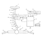
図1は、本発明の実施の形態を示す概略構成図であって、図中、1はステアリングホイールであり、このステアリングホイール1に運転者から作用される操舵力がステアリングシャフト2に伝達される。このステアリングシャフト2は、入力軸2aと出力軸2bとを有し、入力軸2aの一端がステアリングホイール1に連結され、他端はトルク検出手段としてのトルクセンサ3を介して出力軸2bの一端に連結されている。
Embodiments of the present invention will be described below.
FIG. 1 is a schematic configuration diagram showing an embodiment of the present invention, in which 1 is a steering wheel, and a steering force applied to the steering wheel 1 from a driver is transmitted to a
そして、出力軸2bに伝達された操舵力は、ユニバーサルジョイント4を介してロアシャフト5に伝達され、さらにユニバーサルジョイント6を介してピニオンシャフト7に伝達される。
このピニオンシャフト7に伝達された操舵力はステアリングギヤ8を介してタイロッド9に伝達され、図示しない転舵輪を転舵させる。ここで、ステアリングギヤ8は、ピニオンシャフト7に連結されたピニオン8aとこのピニオン8aに噛合するラック8bとを有するラックアンドピニオン形式に構成され、ピニオン8aに伝達された回転運動をラック8bで直進運動に変換している。
The steering force transmitted to the
The steering force transmitted to the
ステアリングシャフト2の出力軸2bには、補助操舵力を出力軸2bに伝達する減速ギヤ10が連結されており、この減速ギヤ10には、操舵系に対して補助操舵力を発生する電動モータ12の出力軸が連結されている。
トルクセンサ3は、ステアリングホイール1に付与されて入力軸2aに伝達された操舵トルクを検出するもので、例えば、操舵トルクを入力軸2a及び出力軸2b間に介挿した図示しないトーションバーの捩れ角変位に変換し、この捩れ角変位を例えばポテンショメータで検出するように構成されている。このトルクセンサ3から出力されるトルク検出値Tは、コントローラ13に入力される。
A reduction gear 10 that transmits an auxiliary steering force to the
The torque sensor 3 detects the steering torque applied to the steering wheel 1 and transmitted to the
このコントローラ13には、トルク検出値Tの他に、車速センサ15で検出した車速検出値V及びエンジン回転数センサ25で検出したエンジン回転数Neも入力され、コントローラ13では、入力されるトルク検出値T及び車速検出値Vに応じた操舵補助力を電動モータ12で発生する操舵補助指令値IM *を公知の手順で算出し、算出した操舵補助指令値IM *とモータ電流検出値IMDとにより、電動モータ12に供給する駆動電流をフィードバック制御するためのモータ駆動電流IMを算出する。
In addition to the torque detection value T, the
また、イグニッションスイッチIGがオン状態となったとき、エンジン回転数センサ25で検出したエンジン回転数Neに基づいて、後述の電源安定化用コンデンサ35へのプリチャージ量を制御しつつ電源安定化用コンデンサ35へのプリチャージを行い、プリチャージ終了後、後述の電源リレー回路30をオン状態に切り換える。また、リレー溶着等の異常検出を行い、異常検出時には、警報装置50を作動して警報を発する。
Further, when the ignition switch IG is turned on, based on the engine speed Ne detected by the
コントローラ13は、図2に示すように、公知の手順で、電動モータ12の制御処理を実行するマイクロコンピュータ16と、マイクロコンピュータ16から出力されるモータ駆動電流IMが入力されて電動モータ12に供給する駆動電流を制御するモータ駆動回路18と、電動モータ12に流れる駆動電流を検出するモータ電流検出回路19と、バッテリ36からモータ駆動回路18への電力供給を遮断するための電源リレー部30と、モータ駆動回路18へ供給される電源電圧を安定化するための電源安定化用コンデンサ35と、当該電源安定化用コンデンサ35にプリチャージを行うプリチャージ回路40と、を備えている。また、前記バッテリ36には、エンジンにより駆動されて発電し前記バッテリ36への充電を行う発電機36aを備えている。
As shown in FIG. 2, the
ここで、モータ駆動回路18は、電界効果トランジスタFET1〜FET4でなる公知のHブリッジ回路20と、マイクロコンピュータ16から出力されるモータ駆動電流IMに基づいてHブリッジ回路20の各電界効果トランジスタFET1〜FET4の各ゲートを駆動するFETゲート駆動回路21とで構成され、前記電界効果トランジスタFET1及びFET2の接続点に、システム内部で生成された内部電圧Vrが印加され、FET3及びFET4の接続点が抵抗Rを介して接地されている。
Here, the
電源リレー部30は、リレー接点31及びこのリレー接点31を付勢するリレーコイル32からなる電源リレー回路33と、リレーコイル32に対する印加電圧を制御する印加電圧制御用能動素子としてのトランジスタ34とを有し、リレー接点31はその一端がHブリッジ回路20の電界効果トランジスタFET1及びFET2の接続点に接続され、他端はバッテリ36に接続される。また、トランジスタ34のソース端子には後述の内部電圧Vbが印加され、ドレイン端子にはリレーコイル32の一端が接続されその他端は接地される。
そして、このリレー接点31と前記電界効果トランジスタFET1及びFET2の接続点との間に、電源安定化用コンデンサ35の一端が接続されその他端は接地される。
The
One end of the power stabilization capacitor 35 is connected between the
プリチャージ回路40は、前記電源安定化用コンデンサ35の高電位側に接続される、電源安定化用コンデンサ35側への逆電圧の印加を防止するための逆電圧素子用のダイオード41と、電界効果トランジスタで構成され、電源安定化用コンデンサ35へのプリチャージ電流を制御するプリチャージ電流制御用トランジスタ42と、このプリチャージ電流制御用トランジスタ42のソース端子に一端が接続される突入電流抑制用抵抗43と、差動アンプで構成される電位差検出回路44と、から構成され、プリチャージ電流制御用トランジスタ42のドレイン端子が突入電流抑制用抵抗43の一端に接続され、その他端はダイオード41のアノード側に接続される。
The
また、前記ダイオード41のカソード側は、イグニッションスイッチIGを介してバッテリ36に接続されると共に、後述の電源自己保持用トランジスタ52を介してバッテリ36に接続され、イグニッションスイッチIGとダイオード41との間にイグニッションスイッチIG側への逆電圧素子用のダイオード51が接続され、また、ダイオード41と電源自己保持用トランジスタ52との間及び電源自己保持用トランジスタ52とバッテリ36との間には、それぞれバッテリ36側への逆電圧素子用のダイオード53及び54が介挿されている。つまり、ダイオード41のカソード側には、バッテリ36の出力電圧がイグニッションスイッチIGを通る経路と、電源自己保持用トランジスタ52を通る経路とにより印加され、このダイオード41のカソード側の電圧が内部電圧Vbとして、前記電源リレー部30のトランジスタ34のソース端子に印加される。
The cathode side of the
前記プリチャージ電流制御用トランジスタ42のゲート端子には、マイクロコンピュータ16からのプリチャージ制御信号Spが入力され、プリチャージ制御信号Spにより電源安定化用コンデンサ35のチャージ量が制御される。
また、電源リレー回路33のリレー接点31のバッテリ側端子の電位及びリレー接点31のコンデンサ側の電位が電位差検出回路44に入力され、これらリレー接点31の両接点の電位差が検出され、これが図示しないA/D変換器を介して接点電位差としてマイクロコンピュータ16に入力される。
A precharge control signal Sp from the
Further, the potential of the battery side terminal of the
また、リレー接点31のバッテリ側端子が図示しない電圧検出器(電源側接点電圧検出手段)によって検出され、また、コンデンサ側端子の電圧が図示しない電圧検出器によって検出され、これらがA/D変換されてそれぞれ接点前段電圧、すなわちバッテリ側接点電圧及び、接点後段電圧、すなわちコンデンサ側接点電圧としてマイクロコンピュータ16に入力される。
Further, the battery side terminal of the
一方、前記電源自己保持用トランジスタ52のゲート端子には、マイクロコンピュータ16からの電源自己保持信号Skが入力される。電源自己保持用トランジスタ52は、イグニッションスイッチIGが閉状態となりマイクロコンピュータ16が起動されたときにオン状態に制御され、イグニッションスイッチIGを介さず直接に、バッテリ36からの電力供給を可能とする。また、イグニッションスイッチIGがオフ状態となったときには、所定の処理が行われ電源リレー回路33が開状態に制御された後、オフ状態に制御される。
On the other hand, a power supply self-holding signal Sk from the
マイクロコンピュータ16は、バッテリ36を電圧源として生成される内部電圧Vcを電源としてイグニッションスイッチIGがオフである間も動作可能に構成されている。そして、イグニッションスイッチIGがオン状態となると、電源自己保持信号Skを出力して電源自己保持用トランジスタ52をオン状態に制御し、イグニッションスイッチIGを介さない、バッテリ36から直接の電力供給を開始する。
The
また、マイクロコンピュータ16は、プリチャージ用トランジスタ42をPWM制御しデューティ比制御を行うことで、電源リレー回路33の端子間の電位差及びエンジン回転数センサ25で検出したエンジン回転数Neに応じて、電源安定化用コンデンサ35へのプリチャージ量を制御し、電源リレー回路33の両接点の電位差が突入電流の生じない程度の値となったときプリチャージを終了すると共に電源リレー回路33をオン状態に切り換える。
そして、車速センサ15及びトルクセンサ3の検出信号に基づいて公知の手順でモータ駆動制御処理を行い、運転者の操舵操作に応じた操舵補助力を発生する。
Further, the
Then, based on detection signals from the
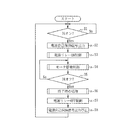
図3は、マイクロコンピュータ16で実行される操舵補助制御処理の処理手順の一例を示すフローチャートである。
マイクロコンピュータ16では、まず、ステップS1で、イグニッションスイッチIGがオン状態となったかどうかを判断する。そして、イグニッションスイッチIGがオン状態となったならば、ステップS2に移行し、電源自己保持信号Skを出力し、電源自己保持用トランジスタ52をオン状態に制御する。これによって、イグニッションスイッチIGを介さずに、バッテリ36から直接電力供給が行われる。
FIG. 3 is a flowchart showing an example of a processing procedure of steering assist control processing executed by the
The
次いで、ステップS3に移行し、電源リレー回路33をオン状態に制御するための、後述の電源リレーオン制御処理を行う。そして、電源リレー回路33をオン状態に制御し、システム各部への電源リレー回路33を介してのバッテリ36からの電力供給を開始した後、ステップS4に移行し、車速センサ15及びトルクセンサ3の検出信号に基づいて、運転者の操舵操作に応じた操舵補助力を発生させるためのモータ駆動制御処理を公知の手順で行う。
Next, the process proceeds to step S3, and a power relay on control process described later for controlling the
次いで、ステップS5に移行し、イグニッションスイッチIGがオフ状態となったかどうかを判断し、オフ状態となっていなければステップS4に戻って引き続きモータ駆動制御処理を行い、イグニッションスイッチIGがオフ状態となったときステップS6に移行する。
このステップS6では、ステアリングホイール1を徐々に中立状態に戻す等、操舵補助制御終了時の所定の処理を行った後、ステップS7に移行し、電源リレー部30のトランジスタ34への電源リレー制御信号Srの出力を停止して、電源リレー回路33を開状態に制御する。次いで、ステップS8に移行して、電源自己保持信号Skの出力を停止して電源自己保持用トランジスタ52をオフ状態に切り換え、電源自己保持用トランジスタ52を介してのバッテリ36からの電力供給を遮断する。そして、ステップS1に戻り、イグニッションスイッチIGがオン状態となるのを監視する。
Next, the process proceeds to step S5, where it is determined whether or not the ignition switch IG is turned off. If the ignition switch IG is not turned off, the process returns to step S4 to continue the motor drive control process, and the ignition switch IG is turned off. When this happens, the process proceeds to step S6.
In step S6, a predetermined process at the end of the steering assist control, such as gradually returning the steering wheel 1 to the neutral state, is performed. Then, the process proceeds to step S7, and the power relay control signal to the
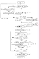
前記ステップS3で実行される電源リレーオン制御処理は、図4に示す処理手順で行われる。
まず、ステップS11で、電源リレー回路33のリレー接点31の接点前段電圧、すなわち、バッテリ側接点電圧を読み込み、このバッテリ側接点電圧が予め設定したしきい値よりも高いかどうかを判断する。このしきい値は、バッテリ36のバッテリ電圧の大きさを判断するためのしきい値であって、例えばバッテリ36の初期のプリチャージ量に応じて設定される。
The power relay on control process executed in step S3 is performed according to the process procedure shown in FIG.
First, in step S11, the pre-contact voltage of the
そして、バッテリ側接点電圧が予め設定したしきい値以下の場合、すなわち、クランキングによってバッテリ電圧が低下した場合等、バッテリ電圧が比較的低い場合には、ステップS13に移行し、次に、電位差検出回路44からの検出信号に基づき、電源リレー回路33の接点電位差が予め設定したしきい値よりも小さいかどうかを判断する。このしきい値は、プリチャージを行うことにより、電源安定化用コンデンサ35の充電電圧が、バッテリ36のバッテリ電圧よりも上昇することを回避することの可能な値に設定される。
When the battery side contact voltage is equal to or lower than a preset threshold value, that is, when the battery voltage is relatively low, such as when the battery voltage is reduced by cranking, the process proceeds to step S13, and then the potential difference Based on the detection signal from the detection circuit 44, it is determined whether or not the contact potential difference of the
そして、電源リレー回路33の接点電位差が予め設定したしきい値よりも小さいときには、ステップS13からステップS14に移行し、バッテリ電圧が低く、また接点電位差も小さいことから、プリチャージを行うことにより電源リレー回路33のコンデンサ側接点電位が上昇しバッテリ側接点電位に近づき過ぎる状態となる可能性があるため、これを回避するために電源安定化用コンデンサ35のプリチャージ量を減少させる。すなわち、プリチャージ制御信号Spの出力を停止し、プリチャージ用トランジスタ42をオフ状態に切り換える。これによって、電源安定化用コンデンサ35の充電電圧が、例えば、バッテリ側接点電圧を検出するための電圧検出器を構成する、一端が接地された抵抗等を介して放電される。このため、コンデンサ側接点電圧が低下し、コンデンサ側接点電圧がバッテリ側接点電圧に近づき過ぎる状態となることが回避される。このとき、後述の図5に示すパターンAの減少度合で変化させる。そして、後述のステップS15に移行する。
When the contact potential difference of the power
一方、ステップS13で接点電位差がしきい値以上である場合には、そのままステップS11に戻る。
また、ステップS11で、バッテリ側接点電圧がしきい値よりも高いときには、ステップS12に移行し、プリチャージ制御信号Spを出力し、プリチャージを開始する。このとき、電源安定化用コンデンサ35のプリチャージ量が比較的増加度合の緩やかなパターンBの増加度合で増加し得るプリチャージ制御信号を出力する。
On the other hand, if the contact potential difference is greater than or equal to the threshold value in step S13, the process directly returns to step S11.
In step S11, when the battery side contact voltage is higher than the threshold value, the process proceeds to step S12, the precharge control signal Sp is output, and the precharge is started. At this time, a precharge control signal is output that can increase the precharge amount of the power stabilization capacitor 35 with the pattern B having a relatively slow increase rate.
ここで、プリチャージ量の変化度合は、図5に示すように、パターンA、パターンB、パターンC及びパターンDの4種類が設定され、パターンAが最もその変化度合が小さく、パターンB、パターンC、パターンDの順に変化度合が大きくなり、パターンDが最も変化度合が大きくなるように設定される。なお、図5において、横軸は時間、縦軸は、電源安定化用コンデンサ35のプリチャージ量である。このように、電源安定化用コンデンサ35を放電させる場合のパターンAの変化度合よりも、プリチャージを行う際のパターンB、C、Dの変化度合をより大きな変化度合に設定することによって、電源電圧により、より早く、的確にプリチャージ量を制御することができる。 Here, as shown in FIG. 5, four types of change of the precharge amount are set: pattern A, pattern B, pattern C, and pattern D, and pattern A has the smallest change, pattern B, pattern The degree of change increases in the order of C and pattern D, and the pattern D is set to have the highest degree of change. In FIG. 5, the horizontal axis represents time, and the vertical axis represents the precharge amount of the power stabilization capacitor 35. Thus, by setting the degree of change of the patterns B, C, and D when precharging to a larger degree of change than the degree of change of the pattern A when discharging the power stabilization capacitor 35, the power supply The precharge amount can be controlled more quickly and accurately by the voltage.
次いで、ステップS15に移行し、エンジン回転数センサ25で検出したエンジン回転数Neを読み込み、このエンジン回転数Neに基づき、エンジンが回転しているか、エンジンが回転している場合にはその回転数がしきい値より小さいかどうかを判断する。なお、このしきい値は、エンジンが始動し、発電機36aによる発電が開始されたかどうかを判断するためのしきい値であって、アイドリング回転数に基づいて設定され、例えば、800〔rpm〕(エンジン始動時1500〔rpm〕)程度に設定される。
Next, the process proceeds to step S15, where the engine speed Ne detected by the
そして、エンジンが回転していないと判断されるときにはクランキング中と判断しステップS15からステップS11に戻る。一方、エンジンが回転してはいるが、しきい値よりも小さく低回転しているときにはステップS16に移行し、接点電位差が予め設定したしきい値よりも小さいかどうかを判断する。この接点電位差のしきい値は、電源リレー回路33の両接点間の電位差が、電源リレー回路33を閉状態に切り換えた場合に、設定値以上の突入電流が流れることのない電位差であるかどうかを判断するためのしきい値である。
When it is determined that the engine is not rotating, it is determined that cranking is being performed, and the process returns from step S15 to step S11. On the other hand, if the engine is rotating but is smaller than the threshold value and is rotating at a lower speed, the process proceeds to step S16 to determine whether or not the contact potential difference is smaller than a preset threshold value. The threshold value of the contact potential difference is whether the potential difference between the two contacts of the
接点電位差がしきい値よりも小さいときには、電源リレー回路33を閉状態に切り換えたとしても設定値以上の突入電流が流れることはないと判断し、ステップS21に移行する。逆に、接点電位差がしきい値以上であるときには、電源リレー回路33を閉状態に切り換えたときに設定値以上の突入電流が流れる可能性があると判断し、ステップS18に移行する。そして、エンジンが比較的低回転しているため、発電機36aによる充電が遅いことからバッテリ36の電源電圧の増加が遅く、また、接点電位差が大きいことから、バッテリ側接点電圧及びコンデンサ側接点電圧の電位差が縮まって接点電位差がしきい値を下回るまでに時間がかかるため、速やかなプリチャージが必要と判断し、比較的速やかにプリチャージを行うパターンDでのプリチャージに切り換える。
When the contact potential difference is smaller than the threshold value, even if the
一方、ステップS15で、エンジン回転数Neがしきい値よりも大きく比較的高回転している場合には、中程度の増加度合でプリチャージを行うパターンCで一端プリチャージを行った後、ステップS16に移行して電源リレー回路33の接点電位差がしきい値より小さいかどうかを判断し、接点電位差がしきい値以上であるときには速やかなプリチャージが必要と判断してより早い増加速度でプリチャージを行うパターンDでのプリチャージに切り換える。
On the other hand, if the engine speed Ne is larger than the threshold value and is relatively high in step S15, the precharge is performed once with the pattern C in which the precharge is performed at a moderate increase degree. In S16, it is determined whether or not the contact potential difference of the power
そして、ステップS16で、電源リレー回路33の接点電位差がしきい値よりも小さくなったときステップS21に移行し、プリチャージ制御信号Spの出力を停止し、プリチャージ用トランジスタ42をオフ状態に切り換え、ステップS22に移行して電源リレー制御信号Srを出力する。これによって、電源リレー部30のトランジスタ34がオン状態となり、内部電圧Vbが励磁コイル32に印加されることからリレーコイル32が励磁されて電源リレー回路33が閉状態に切り換わる。
そして、電源リレー制御信号Srを出力した後、これに応じて電源リレー回路33が閉状態に切り換わるまでの所要時間が経過した時点で、ステップS23に移行し、電源リレー回路33の接点電位差を読み込み、接点電位差の有無を判断する。そして、接点電位差が無い場合には電源リレー回路33にリレー溶着が生じていると判断する。
In step S16, when the contact potential difference of the power
Then, after the power relay control signal Sr is output, when the time required for the
つまり、ステップS21では、電源リレー回路33の接点電位差がしきい値よりも小さくなった時点(ステップS16)でプリチャージを停止し電源リレー回路33をオン状態に切り換えているため、電源リレー回路33が正常に動作していれば、電源リレー回路33が閉状態に切り換えられた時点で電源リレー回路33の両端には、しきい値相当の電位差があるはずである。したがって、電源リレー回路33を閉状態に切り換えた時点で電位差がないということは、すなわち電源リレー回路33を閉状態に切り換える以前に電源リレー回路33は導通状態となっていたとみなすことができ、リレー溶着等の異常が生じているとみなすことができる。
このため、ステップS23で接点電位差がない場合には、電源リレー回路33の異常と判断し、ステップS25に移行する。
That is, in step S21, since the precharge is stopped and the power
For this reason, when there is no contact potential difference in step S23, it is determined that the power
一方、ステップS23で接点電位差がある場合には、リレー溶着等電源リレー回路33は正常に動作可能と判断しステップS24に移行し、次に、接点前段電圧から接点後段電圧を減算した差分値、すなわち、バッテリ側接点電圧からコンデンサ側接点電圧を減算した差分値が、予め設定したしきい値よりも小さいかどうかを判断する。そして、差分値が予め設定したしきい値以上であるときには、何れかの箇所で地絡が生じている、或いは、電源リレー回路33が閉状態に切り換わっていない等、断線異常が生じていると判断し、ステップS25に移行する。一方、差分値がしきい値より小さいときには地絡等の断線異常は生じておらず正常と判断し、処理を終了する。
On the other hand, if there is a contact potential difference in step S23, it is determined that the
前記ステップS23又はステップS24で異常を検出した場合には、ステップS25に移行し、電源リレー制御信号Srの出力を停止すると共に、カウンタを“1”だけインクリメントする。このカウンタは、電源リレー回路33を開閉動作させた回数をカウントするためのカウンタである。次いで、ステップS26に移行して、カウンタ値が予め設定した開閉回数nに達したかどうかを判断し、この開閉回数nに達していないときにはステップS22に戻って、再度電源リレー制御信号Srを出力し、電源リレー回路33を閉状態に制御する。
If an abnormality is detected in step S23 or step S24, the process proceeds to step S25, the output of the power relay control signal Sr is stopped, and the counter is incremented by “1”. This counter is a counter for counting the number of times the power
そして、ステップS23で再度、電源リレー回路33の接点電位差の有無を判断し、接点電位差がある場合にはステップS24でバッテリ側接点電圧からコンデンサ側接点電圧を減算した差分値が正常であるかどうかを判断し、何れかを満足しないときにはステップS25に移行し、再度電源リレー制御信号Srの出力を停止して電源リレー回路33を開状態に切り換える。
In step S23, it is determined again whether or not there is a contact potential difference of the
そして、ステップS22からステップS26の処理を繰り返し行い、カウンタが規定回数nに達する以前に、ステップS23及びステップS24で正常と判断されたとき、つまり、一度は異常と判断されたが、開閉動作を行ったことで、リレー溶着しかかっていたがリレー接点41が開閉動作可能な状態に復帰した場合、或いは、リレー接点41に異物等が挟まっていたがこれが除去された場合等、正常に復帰した場合には、システムは正常と判断して処理を終了する。
Then, the processing from step S22 to step S26 is repeated, and when it is determined that the counter is normal in steps S23 and S24 before the counter reaches the specified number n, that is, once it is determined to be abnormal, the opening / closing operation is performed. As a result, the relay contact was restored, but the
一方、電源リレー回路33の開閉動作を規定回数n回行ってもステップS23又はステップS24で異常と判断されるときには、ステップS27に移行し、異常検出時の処理を実行する。例えば、運転席近傍に設けられた、異常を警告するための警報装置50を作動させ、システムの異常を運転者に通知し、電源リレー回路33をオフ状態、電源自己保持用トランジスタ52を開状態に切り換え、システム各部への電源供給を遮断し、以後、異常が回復するまでの間、操舵補助制御処理を行わない等の対処を行う。
On the other hand, if it is determined that there is an abnormality in step S23 or step S24 even if the power
次に、上記実施の形態の動作を説明する。
イグニッションスイッチがオン状態となると、マイクロコンピュータ16は、図3のステップS1からステップS2に移行し、電源自己保持信号Skを出力し、電源自己保持用トランジスタ52をオン状態に切り換える。そして、電源リレーオン制御処理を実行する(ステップS3)。
このときプリチャージ回路40には、イグニッションスイッチIG及び電源自己保持用トランジスタ52を介してバッテリ36から電力供給が行われるから、電源リレー回路33がオン状態となっていない状態であってもプリチャージが可能である。
Next, the operation of the above embodiment will be described.
When the ignition switch is turned on, the
At this time, since power is supplied from the
そして、クランキング等によりバッテリ電圧が低下し、電源リレー回路33のバッテリ側接点電圧が比較的小さくしきい値以下であり、且つ、バッテリ側接点電圧とコンデンサ側接点電圧との接点電位差が比較的大きくしきい値以上である間は、ステップS11からステップS13を経てステップS11に戻る。そして、エンジン始動に伴う発電機36aの発電によりバッテリ側接点電圧が予め設定したしきい値よりも高くなるとき、ステップS11からステップS12に移行し、比較的緩やかな増加度合のパターンBでのプリチャージを開始する。
The battery voltage drops due to cranking or the like, the battery side contact voltage of the
一方、バッテリ側接点電圧がしきい値よりも低い状態で、さらにバッテリ側接点電圧とコンデンサ側接点電圧との接点電位差がしきい値を下回るときには、ステップS13からステップS14に移行し、プリチャージ用トランジスタ42をオフ状態に切り換え、電源安定化用コンデンサ35の放電を行い、電源安定化用コンデンサ35を放電させる。これによって、後にプリチャージを行った場合であってもコンデンサ側接点電圧がバッテリ側接点電圧に近づき過ぎることはなく、電源安定化用コンデンサ35の充電電圧がバッテリ36の電源電圧を上回ることはない。
On the other hand, when the battery-side contact voltage is lower than the threshold value and the contact potential difference between the battery-side contact voltage and the capacitor-side contact voltage is lower than the threshold value, the process proceeds from step S13 to step S14 for precharging. The
そして、ステップS15に移行し、エンジンが回転していなければ、ステップS11に戻り、バッテリ側接点電圧がしきい値よりも小さいときにはステップS11からステップS13に移行し、電源安定化用コンデンサ35の放電によりバッテリ側接点電圧とコンデンサ側接点電圧との接点電圧差がしきい値以上となるとそのままステップS11に戻る。
そして、エンジン始動に伴う発電機36aの発電によりバッテリ側接点電圧が予め設定したしきい値よりも高くなったとき、ステップS11からステップS12に移行し、比較的緩やかな増加度合のパターンBでのプリチャージを開始する。
Then, the process proceeds to step S15, and if the engine is not rotating, the process returns to step S11. When the battery side contact voltage is smaller than the threshold value, the process proceeds from step S11 to step S13, and the power stabilization capacitor 35 is discharged. Thus, when the contact voltage difference between the battery side contact voltage and the capacitor side contact voltage is equal to or greater than the threshold value, the process directly returns to step S11.
When the battery-side contact voltage becomes higher than a preset threshold value due to the power generation of the
一方、放電を行った段階でエンジンが回転しており、このとき、エンジンが比較的高回転している場合には、ステップS15からステップS17に移行し、中程度の増加度合のパターンCでプリチャージが行われる。そして、このプリチャージによって電源リレー回路33の接点電位差がしきい値よりも小さくなっていれば、ステップS16からステップS21に移行し、プリチャージを終了するが、接点電位差がしきい値以上である場合には、ステップS18に移行し、パターンCよりも増加度合の大きなパターンDでのプリチャージが行われ、速やかにプリチャージが行うことでプリチャージ時間の短縮が図られる。
On the other hand, if the engine is rotating at the stage where the discharge is performed and the engine is rotating at a relatively high speed, the process proceeds from step S15 to step S17, and the pattern C with a medium increase degree is pre-processed. Charging is performed. If the contact potential difference of the power
このとき、エンジンが比較的高回転をしている場合には、発電機36aによる充電が比較的速やかに行われ、バッテリ電圧は比較的速やかに上昇するから、中程度の増加度合でプリチャージを行ったとしても電源安定化用コンデンサ35の充電電圧がバッテリ電圧に近づき過ぎることはない。また、一旦、中程度の増加度合のパターンCでのプリチャージを行った後、接点電位差の大きさを判断し、その後、増加度合の大きなパターンDでプリチャージを行っているから、エンジン始動後、増加度合の大きなパターンDでのプリチャージを行うことで、電源安定化用コンデンサ35の充電電圧が、バッテリ電圧に近づき過ぎることを回避することができる。
At this time, when the engine is running at a relatively high speed, the
一方、エンジン回転数が比較的小さい場合には、ステップS15からそのままステップS16に移行し、電源リレー回路33の接点電位差が小さければステップS21に移行してプリチャージを終了するが、接点電位差が大きいときには、ステップS18に移行してパターンDでのプリチャージが行われ、速やかにプリチャージを行うことでプリチャージ時間の短縮が図られる。
On the other hand, when the engine speed is relatively small, the process proceeds from step S15 to step S16 as it is, and if the contact potential difference of the power
ここで、エンジン回転数が比較的小さい場合にはバッテリ電圧の上昇が遅いことから、パターンCやパターンDといった比較的大きな増加度合でプリチャージを行った場合、場合によっては、電源安定化用コンデンサ35の充電電圧がバッテリ電圧に近づき過ぎる可能性がある。しかしながら、エンジンが比較的低回転している場合には、まず、ステップS16で接点電位差の大きさを判断し、プリチャージが必要な場合には、パターンDによる、速やかなプリチャージを行っているから、電源安定化用コンデンサ35の充電電圧がバッテリ電圧に近づき過ぎることはなく、且つ、接点電位差が大きい場合には速やかにプリチャージを行って接点電位差を小さくすることができ、プリチャージ時間を短縮することができる。 Here, when the engine speed is relatively small, the battery voltage rises slowly. Therefore, when precharging is performed at a relatively large increase rate such as pattern C or pattern D, the power stabilization capacitor may be used in some cases. There is a possibility that the charging voltage of 35 is too close to the battery voltage. However, if the engine is running at a relatively low speed, first, the magnitude of the contact potential difference is determined in step S16, and if precharge is required, the pattern D is quickly precharged. Therefore, when the charging voltage of the power stabilization capacitor 35 does not approach the battery voltage too much and the contact potential difference is large, the contact potential difference can be reduced quickly by reducing the contact potential difference. It can be shortened.
一方、イグニッションスイッチIGがオン状態となったときに、クランキングによってバッテリ電圧がそれほど低下せず、バッテリ側接点電位がそのしきい値を上回る場合には、ステップS11からそのままステップS12に移行し、そのままパターンBにしたがって比較的緩やかな増加度合でのプリチャージが開始され、エンジンが回転していなければ、ステップS15からステップS11に戻って、ステップS11、S12、S15の処理が繰り返し行われ、パターンBでのプリチャージが継続される。この場合、バッテリ側接点電位は比較的高いことからパターンBでのプリチャージを継続した場合でも、電源安定化用コンデンサ35の充電電圧がバッテリ36の電源電圧に近づき過ぎることはない。
On the other hand, when the ignition switch IG is turned on, if the battery voltage does not decrease so much by cranking and the battery side contact potential exceeds the threshold value, the process proceeds from step S11 to step S12 as it is. If the precharge is started according to the pattern B as it is and the engine is not rotating, the process returns from step S15 to step S11, and the processes of steps S11, S12, and S15 are repeated. The precharge at B continues. In this case, since the battery-side contact potential is relatively high, even when the precharge in the pattern B is continued, the charging voltage of the power stabilization capacitor 35 does not approach the power supply voltage of the
そして、エンジンが始動されると、エンジン回転数が低ければ、ステップS16に移行して電源リレー回路33の接点電位差の大きさが判断され、接点電位差が大きいときにはパターンDでの速やかなプリチャージが図られる。一方、エンジン始動時のエンジン回転数が高ければステップS17に移行してパターンCでの中程度の増加度合でのプリチャージが行われた後、ステップS16に移行し、接点電位差が大きければステップS18に移行してパターンDでの速やかなプリチャージが図られる。
When the engine is started, if the engine speed is low, the process proceeds to step S16, where the magnitude of the contact potential difference of the power
ここで、バッテリ側接点電位がしきい値よりも高く、この状態でプリチャージを行ったとしても電源安定化用コンデンサ35の充電電圧がバッテリ電圧に近づき過ぎる可能性が低いときには、エンジンの回転の有無に関わらず、この時点でプリチャージを開始しているからより早い段階でプリチャージを開始することで、プリチャージ時間を短縮することができる。また、このとき、比較的緩やかな増加度合のパターンBによりプリチャージを行っているから、このプリチャージにより、電源安定化用コンデンサ35の充電電圧がバッテリ電圧に近づき過ぎる状態となることを回避することができる。 Here, when the battery-side contact potential is higher than the threshold value, and the precharge is performed in this state, it is unlikely that the charging voltage of the power stabilization capacitor 35 is too close to the battery voltage. Regardless of the presence or absence, the precharge is started at this point, so that the precharge time can be shortened by starting the precharge at an earlier stage. At this time, since the precharge is performed with the pattern B having a relatively gradual increase degree, the precharge prevents the charging voltage of the power stabilization capacitor 35 from being too close to the battery voltage. be able to.
そして、電源リレー回路33の接点電位差がしきい値より小さくなったとき、ステップS16からステップS21に移行し、プリチャージ制御信号Spの出力を停止してプリチャージ用トランジスタ42をオフ状態に切り換えてプリチャージを終了し、続いて、電源リレー制御信号Srを出力して、電源リレー部30のトランジスタ34をオン状態に切り換える。これによって、リレーコイル32への電圧印加が開始され、電源リレー回路33がオン状態に切り換えられる。
When the contact potential difference of the power
このとき、電源リレー回路33の接点電位差はしきい値よりも小さく、このしきい値は、設定値以上の突入電流が流れることのない値に設定されているから、電源リレー回路33が閉状態に切り換わったとしても設定値以上の突入電流が生じることはない。したがってこの設定値以上の突入電流が流れることに起因する、リレー溶着やリレーの磨耗等の発生を抑制することができる。
At this time, the contact potential difference of the power
そして、電源リレー回路33がオン状態に切り換わったとみなすことのできる所要時間が経過した時点での接点電位差に基づいて異常判断が行われ、このとき、電源リレー回路33にリレー溶着等が生じていない場合には、電源リレー回路33がオフ状態のときには、しきい値相当の接点電位差があるから、オン状態に切り換わった直後でもある程度の接点電位差が生じることになる。したがって、電源リレー回路33がオン状態に切り換わった直後に、接点電位差がある場合にはリレー溶着は生じていないと判断される(ステップS23)。さらに、接点前段電圧から接点後段電圧を減算した値、すなわち接点電位差が、しきい値よりも小さいということは、すなわち、地絡等が生じていないことを意味するから、システムは正常と判断される(ステップS24)。
Then, abnormality determination is performed based on the contact potential difference at the time when the required time that can be considered that the
そして、システムは正常であることから図3に戻って車速センサ15やトルクセンサ3の検出信号に基づいてモータ駆動制御処理が行われ(ステップS4)、運転者の操舵操作に応じた操舵補助力が発生される。
この状態から、イグニッションスイッチIGがオフに切り換わると、ステアリングホイール1を中立状態に戻す等の操舵制御処理終了時の処理が行われた後、電源リレー回路33がオフ状態に切り換えられ(ステップS7)、電源自己保持用トランジスタ52がオフ状態に切り換えられる(ステップS8)。
Then, since the system is normal, returning to FIG. 3, the motor drive control process is performed based on the detection signals of the
When the ignition switch IG is switched off from this state, processing at the end of the steering control processing such as returning the steering wheel 1 to the neutral state is performed, and then the
一方、電源リレー回路33にリレー溶着が生じている場合には、電源リレー回路33が閉状態に切り換わった時点で接点電位差がないため異常と判断され、ステップS23からステップS25に移行して電源リレー回路25はオフ状態に切り換えられる。また、例えばシステム内部の何れかに地絡等の断線異常が生じている場合には、電源リレー回路33が閉状態に切り換わった場合でも、接点前段電圧から接点後段電圧を減算した値がしきい値よりも大きくなることから、異常と判断されてステップS24からステップS25に移行する。
On the other hand, if relay welding has occurred in the
そして、電源リレー回路33を一旦オフ状態にて再度オン状態に切り換えた後、接点電位差の有無、或いは、接点電位差が正常であるかどうかが判断される。そして、電源リレー回路33を規定回数n回だけ開閉動作させた場合でも、異常と判断されるときは、運転席近傍に設けられた警報装置50を作動させること等により、システムの異常が運転者に通知され、電源リレー回路33がオフ状態、電源自己保持用トランジスタ52が開状態に切り換えられて、バッテリ36からの電源供給が遮断される。
Then, after the power
ここで、リレー溶着或いは地絡等が生じている可能性があると判断されるときには、電源リレー回路33を規定回数n回だけ開閉操作させているから、場合によっては、リレー接点31を動作可能な状態に復帰させることができる可能性があり、また、リレー接点31に異物等が挟まることによって導通状態とならなかった場合等には電源リレー回路33を開閉動作させることで異物の除去を図ることができる。
Here, when it is determined that there is a possibility of relay welding or ground fault or the like, the
上述のように、電源リレー回路33のバッテリ側及びコンデンサ側の接点の電位差をそれぞれ検出し、これらの差が、突入電流が生じることがないと予測される電位差となったときに電源リレー回路33を閉状態に切り換えるようにしているから設定値以上の突入電流を確実に抑制することができる。したがって、設定値以上の突入電流に起因する、リレー溶着や磨耗等の発生を抑制することができ、電源リレー回路33自体の寿命を延ばすことができる。また、接点間の電位差を監視しているから、設定値以上の突入電流が発生しないとみなすことの可能な時点で速やかにプリチャージを終了して電源リレー回路33をオン状態に切り換えることができるから、プリチャージを的確なタイミングで終了することができプリチャージ時間を必要最小限の時間に抑えることができる。
As described above, the potential difference between the battery-side and capacitor-side contacts of the
また、このように設定値以上の突入電流の発生を抑制することができるから、電源リレー回路33を選択する際にその仕様等をそれほど考慮して選択する必要がない。したがって、安価なリレー回路を電源リレー回路33として用いることができ、その分、コスト削減を図ることができる。
また、バッテリ側接点電圧が比較的高いかどうか、また、接点電位差が大きいかどうか、エンジン回転数が高いかどうかに応じて電源安定化用コンデンサ35のプリチャージ量の増加度合を制御し、バッテリ側接点電圧の変化状況及びコンデンサ側接点電圧の変化状況を考慮してプリチャージを行うことができるから、コンデンサ側接点電圧がバッテリ側接点電圧に近づき過ぎることを回避しつつ、速やかにプリチャージを行うことができ、プリチャージ時間の短縮を図ることができる。
In addition, since it is possible to suppress the occurrence of an inrush current exceeding the set value in this way, it is not necessary to select the power
Further, the degree of increase in the precharge amount of the power stabilization capacitor 35 is controlled in accordance with whether the battery side contact voltage is relatively high, whether the contact potential difference is large, and whether the engine speed is high. Precharge can be performed in consideration of the change in the side contact voltage and the change in the capacitor side contact voltage, so that the capacitor side contact voltage is not too close to the battery side contact voltage, and the precharge is performed quickly. This can be done and the precharge time can be shortened.
また、電源リレー回路33のバッテリ側電圧及びコンデンサ側電圧を検出するようにしているから、従来実施されていたリレー溶着や地絡等の断線検出時のように、コンデンサ側電圧が例えば5V以上のときにはリレー溶着と判断したり、また、9V以下のときには断線と判断したりする場合や、バッテリ電圧Vbとコンデンサ側接点電圧とを比較すること等によって異常監視を行う場合に比較して、異常と判断するための電圧範囲をさらに限定することができ、より精度の高い監視を行うことができる。
Further, since the battery side voltage and the capacitor side voltage of the power
また、電源リレー回路33の接点電位差が、設定値以上の突入電流が生じないしきい値を下回った時点でプリチャージを終了し、この時点で電源リレー回路33のリレー溶着診断を行っているから、プリチャージによるコンデンサ側接点電圧の変動がない状態であり、且つ、接点電位差がしきい値よりも小さく電源リレー回路33を導通状態としたときのコンデンサ側接点電圧の変動が比較的安定した状態でリレー溶着診断や地絡等の断線検出を行うことができ、異常判定の誤判断を回避することができる。
Since the precharge is finished when the contact potential difference of the
なお、上記実施の形態においては、電位差検出回路44として、差動アンプを用いた場合について説明したがこれに限るものではない。上述のように、差動アンプを用いて接点電位差を検出することにより、マイクロコンピュータ16での内部演算が不要なため、2−CPU等での別々の監視を容易に行うことができるが、マイクロコンピュータ16に入力される接点前段電圧としてのバッテリ側接点電圧及び接点後段電圧としてのコンデンサ側接点電圧を用いて、マイクロコンピュータ16で、これらの差分値を演算することで、電源リレー回路33の接点電圧差を獲得するようにしてもよい。この場合、差動アンプを設ける必要がないからその分、コスト削減を図ることができる。
In the above embodiment, the case where a differential amplifier is used as the potential difference detection circuit 44 has been described. However, the present invention is not limited to this. As described above, by detecting the contact potential difference using a differential amplifier, internal calculation in the
また、上記実施の形態においては、異常を検出したとき、ステップS22からステップS26の処理を繰り返すことで、1回の開閉動作を行わせる毎に異常かどうかを判断する場合について説明したが、これに限るものではなく、例えば、規定回数n回開閉動作を行った後に、異常かどうかを判断するようにしてもよい。
ここで、上記実施の形態において、マイクロコンピュータ16で電源リレー制御信号Srを出力及び停止を行う処理がリレー制御手段に対応し、図4のステップS23及びステップS24の処理が異常検出手段に対応し、電位差検出回路44が電位差検出手段に対応している。
In the above embodiment, when an abnormality is detected, the process from step S22 to step S26 is repeated to determine whether or not there is an abnormality every time an opening / closing operation is performed. For example, it may be determined whether or not there is an abnormality after performing the opening and closing operation n times a specified number of times.
Here, in the above embodiment, the process of outputting and stopping the power supply relay control signal Sr by the
また、発電機36aが発電手段に対応し、エンジン回転数センサ25がエンジン回転状態検出手段に対応し、図4のステップS11〜ステップS18の処理がプリチャージ量制御手段に対応している。
また、図4のステップS22、ステップS25及びステップS26の処理が開閉制御手段に対応している。
Further, the
Further, the processing of step S22, step S25, and step S26 in FIG. 4 corresponds to the opening / closing control means.
1 ステアリングホイール
2 ステアリングシャフト
3 トルクセンサ
8 ステアリングギヤ
10 減速ギヤ
12 電動モータ
13 コントローラ
14 車速センサ
16 マイクロコンピュータ
18 モータ駆動回路
19 電流検出回路
20 Hブリッジ回路
21 FETゲート駆動回路
31 リレー接点
32 リレーコイル
33 電源リレー回路
35 電源安定化用コンデンサ
36 電源
42 プリチャージ制御用トランジスタ
43 突入電流抑制抵抗
44 電位差検出回路
50 警報装置
DESCRIPTION OF SYMBOLS 1
Claims (6)
当該電動モータを駆動するモータ駆動回路と、
当該モータ駆動回路に電源からの電力を供給する電源リレー回路と、
当該電源リレー回路を制御するリレー制御手段と、
当該電源リレー回路と前記モータ駆動回路との間に介挿された電源安定化用コンデンサと、
前記電源リレー回路を閉じる前に前記電源安定化用コンデンサを充電するプリチャージ回路と、
前記電源リレー回路のリレー接点両端間の電位差を検出する電位差検出手段と、
エンジンにより駆動されて発電し前記電源への充電を行う発電手段と、
前記エンジンが回転中か否かを検出するエンジン回転状態検出手段と、
当該エンジン回転状態検出手段での検出結果に基づきエンジンが回転中か否かに応じて前記電源安定化用コンデンサのプリチャージ量を制御するプリチャージ量制御手段と、を備え、
前記リレー制御手段は、前記電位差検出手段で検出した電位差が予め設定したしきい値より小さくなったとき前記電源リレー回路を閉状態に制御し、
前記プリチャージ量制御手段は、エンジンが非回転中は、回転中よりもより遅い速度でプリチャージを行うことを特徴とする電動パワーステアリング制御装置。 An electric motor for applying a steering assist force to the steering system;
A motor drive circuit for driving the electric motor;
A power relay circuit for supplying power from the power source to the motor drive circuit;
Relay control means for controlling the power relay circuit;
A power stabilization capacitor interposed between the power relay circuit and the motor drive circuit;
A precharge circuit that charges the power stabilization capacitor before closing the power relay circuit;
A potential difference detection means for detecting a potential difference between the relay contacts ends before Symbol power relay circuit,
Power generation means driven by an engine to generate power and charge the power source;
Engine rotation state detection means for detecting whether or not the engine is rotating;
E Bei engine based on a detection result of the in the engine rotational state detecting means and a pre-charge amount control means for controlling the pre-charge amount of the capacitor for the power supply stabilization depending on whether or not the rotation,
The relay control means controls the power relay circuit to be closed when the potential difference detected by the potential difference detection means is smaller than a preset threshold value ,
The electric power steering control device, wherein the precharge amount control means performs precharge at a slower speed when the engine is not rotating than when the engine is rotating .
前記プリチャージ量制御手段は、前記電源側接点電圧検出手段で検出される電源側接点電圧が予め設定したしきい値以下であり、且つ前記電位差検出手段で検出される電位差が予め設定したしきい値より小さいときには前記電源安定化用コンデンサを放電させることを特徴とする請求項1記載の電動パワーステアリング制御装置。 A power supply side contact voltage detection means for detecting a voltage of a contact connected to the power supply side of the power supply relay circuit;
The precharge amount control means is configured such that the power supply side contact voltage detected by the power supply side contact voltage detection means is not more than a preset threshold value, and the potential difference detected by the potential difference detection means is a preset threshold. electric power steering controller of claim 1 Symbol mounting, characterized in that discharging the capacitor the power supply stabilizing when less than the value.
当該異常検出手段は、前記電源リレー回路が閉状態に制御された後に、前記異常検出を行うことを特徴とする請求項1又は請求項2記載の電動パワーステアリング制御装置。 An abnormality detection means for detecting an abnormality based on a potential difference between both ends of the relay contact detected by the potential difference detection means,
3. The electric power steering control device according to claim 1, wherein the abnormality detection unit performs the abnormality detection after the power supply relay circuit is controlled to be closed.
前記異常検出手段は、前記異常を検出したとき、前記開閉制御手段を作動させ、
前記電源リレー回路を規定回数開閉動作させても前記異常が検出されるとき、異常発生として確定することを特徴とする請求項3から請求項5の何れか1項に記載の電動パワーステアリング制御装置。 The relay control means includes an open / close control means for opening / closing the power relay circuit when an abnormality is detected by the abnormality detection means.
When the abnormality detection unit detects the abnormality, the abnormality detection unit operates the opening / closing control unit,
Wherein when even the power relay circuit is specified number closing operation the abnormality is detected, the electric power steering control apparatus according to claims 3 to any one of claims 5, characterized in that determining an abnormality occurs .
Priority Applications (1)
| Application Number | Priority Date | Filing Date | Title |
|---|---|---|---|
| JP2006107893A JP4882467B2 (en) | 2006-04-10 | 2006-04-10 | Electric power steering control device |
Applications Claiming Priority (1)
| Application Number | Priority Date | Filing Date | Title |
|---|---|---|---|
| JP2006107893A JP4882467B2 (en) | 2006-04-10 | 2006-04-10 | Electric power steering control device |
Publications (2)
| Publication Number | Publication Date |
|---|---|
| JP2007276706A JP2007276706A (en) | 2007-10-25 |
| JP4882467B2 true JP4882467B2 (en) | 2012-02-22 |
Family
ID=38678614
Family Applications (1)
| Application Number | Title | Priority Date | Filing Date |
|---|---|---|---|
| JP2006107893A Expired - Fee Related JP4882467B2 (en) | 2006-04-10 | 2006-04-10 | Electric power steering control device |
Country Status (1)
| Country | Link |
|---|---|
| JP (1) | JP4882467B2 (en) |
Cited By (1)
| Publication number | Priority date | Publication date | Assignee | Title |
|---|---|---|---|---|
| KR20140065572A (en) * | 2012-11-16 | 2014-05-30 | 현대모비스 주식회사 | Ecu for controlling electric power steering apparatus and operating method thereof |
Families Citing this family (14)
| Publication number | Priority date | Publication date | Assignee | Title |
|---|---|---|---|---|
| JP2010074915A (en) | 2008-09-17 | 2010-04-02 | Jtekt Corp | Motor controller and electric power steering device |
| JP4720896B2 (en) | 2008-10-08 | 2011-07-13 | 株式会社デンソー | Abnormality diagnosis device for power supply circuit and power supply circuit |
| JP5402068B2 (en) * | 2009-02-19 | 2014-01-29 | 日本精工株式会社 | Motor control device |
| JP5444992B2 (en) | 2009-09-24 | 2014-03-19 | 株式会社ジェイテクト | Electric power steering device |
| JP2011213255A (en) * | 2010-03-31 | 2011-10-27 | Nsk Ltd | Electric power steering device |
| JP5311233B2 (en) | 2010-12-27 | 2013-10-09 | 株式会社デンソー | Motor control device and electric power steering device using the same |
| JP2013091424A (en) * | 2011-10-26 | 2013-05-16 | Omron Automotive Electronics Co Ltd | Electronic control device |
| JP5888101B2 (en) * | 2012-05-09 | 2016-03-16 | 株式会社デンソー | Control device |
| JP6244110B2 (en) * | 2013-05-31 | 2017-12-06 | 日本電産エレシス株式会社 | Electronic control unit |
| JP5683667B1 (en) * | 2013-10-11 | 2015-03-11 | 三菱電機株式会社 | Electric power steering device |
| KR102393011B1 (en) * | 2018-08-27 | 2022-05-02 | 현대모비스 주식회사 | Method for checking and responding failure of mechanical relay for mdps |
| JP7172306B2 (en) | 2018-09-03 | 2022-11-16 | 株式会社ジェイテクト | vehicle controller |
| JP2020137196A (en) * | 2019-02-15 | 2020-08-31 | 株式会社ミツバ | Motor control device and motor control method |
| KR102897087B1 (en) * | 2023-01-31 | 2025-12-08 | 에이치엘만도 주식회사 | Steering control apparatus and method |
Family Cites Families (5)
| Publication number | Priority date | Publication date | Assignee | Title |
|---|---|---|---|---|
| JPS6062374A (en) * | 1983-09-14 | 1985-04-10 | 松下電工株式会社 | Under-floor accommodation chamber |
| JP3839142B2 (en) * | 1997-09-19 | 2006-11-01 | 本田技研工業株式会社 | Electric motor drive |
| JP3595155B2 (en) * | 1998-03-04 | 2004-12-02 | 本田技研工業株式会社 | Electric motor driving device and electric power steering device |
| JP3560876B2 (en) * | 1999-10-26 | 2004-09-02 | 本田技研工業株式会社 | Hybrid vehicle control device |
| JP3511593B2 (en) * | 2000-11-10 | 2004-03-29 | 三菱電機株式会社 | Electric power steering control device |
-
2006
- 2006-04-10 JP JP2006107893A patent/JP4882467B2/en not_active Expired - Fee Related
Cited By (2)
| Publication number | Priority date | Publication date | Assignee | Title |
|---|---|---|---|---|
| KR20140065572A (en) * | 2012-11-16 | 2014-05-30 | 현대모비스 주식회사 | Ecu for controlling electric power steering apparatus and operating method thereof |
| KR102004685B1 (en) * | 2012-11-16 | 2019-07-30 | 현대모비스 주식회사 | Ecu for controlling electric power steering apparatus and operating method thereof |
Also Published As
| Publication number | Publication date |
|---|---|
| JP2007276706A (en) | 2007-10-25 |
Similar Documents
| Publication | Publication Date | Title |
|---|---|---|
| EP2301822B1 (en) | Electric power steering system | |
| JP4882467B2 (en) | Electric power steering control device | |
| KR0178294B1 (en) | Electric power steering control system | |
| JP3511593B2 (en) | Electric power steering control device | |
| JP5092538B2 (en) | Motor control device and electric power steering control device using the same | |
| CN101678855B (en) | Electric power steering device | |
| JP2012188101A (en) | Controller of electric power steering apparatus | |
| JP2019140883A (en) | Power supply | |
| US20160087572A1 (en) | Motor Drive Device and Motor Drive Method for EPS System | |
| WO2010038702A1 (en) | Electric power steering device | |
| JPWO1999017977A1 (en) | Automotive control devices | |
| JP5088473B2 (en) | Steering device | |
| JP5402068B2 (en) | Motor control device | |
| JPWO2005081386A1 (en) | Relay welding prevention device and motor drive device | |
| JP3595155B2 (en) | Electric motor driving device and electric power steering device | |
| JP5194630B2 (en) | Power control device | |
| JP5407935B2 (en) | Electric power steering device | |
| JP4876716B2 (en) | Electric power steering control device | |
| JP5683667B1 (en) | Electric power steering device | |
| JP4910561B2 (en) | Electric power steering device | |
| JP4899668B2 (en) | Electric power steering control device | |
| JP2013091424A (en) | Electronic control device | |
| JP2006062616A (en) | Vehicle steering assist device | |
| JP2008154422A (en) | Motor drive control device and electric power steering device using the same | |
| JP2011213255A (en) | Electric power steering device |
Legal Events
| Date | Code | Title | Description |
|---|---|---|---|
| RD01 | Notification of change of attorney |
Free format text: JAPANESE INTERMEDIATE CODE: A7421 Effective date: 20090130 |
|
| A621 | Written request for application examination |
Free format text: JAPANESE INTERMEDIATE CODE: A621 Effective date: 20090212 |
|
| RD03 | Notification of appointment of power of attorney |
Free format text: JAPANESE INTERMEDIATE CODE: A7423 Effective date: 20101022 |
|
| RD04 | Notification of resignation of power of attorney |
Free format text: JAPANESE INTERMEDIATE CODE: A7424 Effective date: 20101022 |
|
| A131 | Notification of reasons for refusal |
Free format text: JAPANESE INTERMEDIATE CODE: A131 Effective date: 20110719 |
|
| A977 | Report on retrieval |
Free format text: JAPANESE INTERMEDIATE CODE: A971007 Effective date: 20110721 |
|
| A521 | Request for written amendment filed |
Free format text: JAPANESE INTERMEDIATE CODE: A523 Effective date: 20110912 |
|
| TRDD | Decision of grant or rejection written | ||
| A01 | Written decision to grant a patent or to grant a registration (utility model) |
Free format text: JAPANESE INTERMEDIATE CODE: A01 Effective date: 20111108 |
|
| A01 | Written decision to grant a patent or to grant a registration (utility model) |
Free format text: JAPANESE INTERMEDIATE CODE: A01 |
|
| A61 | First payment of annual fees (during grant procedure) |
Free format text: JAPANESE INTERMEDIATE CODE: A61 Effective date: 20111121 |
|
| FPAY | Renewal fee payment (event date is renewal date of database) |
Free format text: PAYMENT UNTIL: 20141216 Year of fee payment: 3 |
|
| R150 | Certificate of patent or registration of utility model |
Ref document number: 4882467 Country of ref document: JP Free format text: JAPANESE INTERMEDIATE CODE: R150 Free format text: JAPANESE INTERMEDIATE CODE: R150 |
|
| LAPS | Cancellation because of no payment of annual fees |