JP4982691B2 - Sn-containing In oxide, method for producing the same, paint using the same, and conductive coating film - Google Patents
Sn-containing In oxide, method for producing the same, paint using the same, and conductive coating film Download PDFInfo
- Publication number
- JP4982691B2 JP4982691B2 JP2001245701A JP2001245701A JP4982691B2 JP 4982691 B2 JP4982691 B2 JP 4982691B2 JP 2001245701 A JP2001245701 A JP 2001245701A JP 2001245701 A JP2001245701 A JP 2001245701A JP 4982691 B2 JP4982691 B2 JP 4982691B2
- Authority
- JP
- Japan
- Prior art keywords
- axis diameter
- oxide
- less
- minor axis
- particles
- Prior art date
- Legal status (The legal status is an assumption and is not a legal conclusion. Google has not performed a legal analysis and makes no representation as to the accuracy of the status listed.)
- Expired - Lifetime
Links
Images


Description
【0001】
【発明の属する技術分野】
本発明はSn含有In酸化物(ITOということがある。)とその製造方法に関し、さらにそれを用いた塗料ならびに導電性塗膜に関するものである。
【0002】
【従来の技術】
Sn含有In酸化物はITOとも呼ばれ、可視光に対する透光性と高い導電性を示すことから各種表示デバイスや太陽電池などの透明導電膜として用いられている。
このITOを用いた透明導電膜の製法としては、スパッタ法などの物理的方法、粒子分散液または有機化合物を塗布する塗布法が知られている。このうち塗布法による膜は、スパッタ法などの物理的方法による膜に比べて導電性が多少低いものの、真空装置等の高価な装置を用いることなく大面積や複雑形状の成膜が可能であり低コストとなる特徴がある。さらにこの塗布法の中でも粒子分散法は有機化合物を熱分解する方法に比べ比較的低温のプロセスで成膜でき、導電性も得られることからブラウン管の電磁波シールド膜として広く用いられており、LCDやELなどの表示デバイスの透明電極への用途も検討されている。しかしながら、この粒子分散法による塗膜はスパッタ膜などに比べてまだ導電性が低く、ブラウン管の大型化や表示デバイスの高精細電極用にはいまだ対応できないため、これらの用途にも対応できる、透光性を保ちかつ導電性の向上した塗膜を実現するITO粒子の出現が望まれている。
【0003】
導電性塗膜においては、ITO粒子同士の接触により導電経路が形成されるため、この導電経路が得られやすい(すなわち、ITO粒子同士の接触面が多くなるような)粒子の形状として、フレーク状や針状、板状の粒子を用いることによって導電性を向上させる(すなわち抵抗を低下させる)ことができる。種々の粒子形状を得る試みとしては、
(A)長軸長5μm以上、長軸/短軸の軸比5以上の針状ITO粒子を得る方法(特開平7−232920、特開平7−235214)
(B)長さ1〜100μm、幅0.2〜20μm、厚み0.01〜2μmの短冊状酸化チタン粒子に導電性微粒子を被覆する方法(特開平8−217446)
(C)長軸0.2〜0.95μm、短軸0.02〜0.1μm、アスペクト比4以上の針状ITOの製法(特開平6−80422)
などの製法が知られている。しかし、(A)については得られるITO粒子が大きく、抵抗値は低減されるものの、透過率等の光学特性が悪く、特に散乱光が多く発生し塗膜のヘイズが大きくなるという問題がある。(B)については短冊状であり接触点が得られると考えられるが、粒子が大きく(A)と同様の問題があり、さらに、導電性が低い酸化チタン粒子を導電性材料で被覆するので粒子内抵抗が高く塗膜において充分な導電性が得られない。また、(C)については(A)よりも微粒子であり光学特性は多少改善されるが、可視光の波長(400〜700nm)の1/2のサイズより大きく、塗膜中に粒子が充填された場合に散乱光が発生し、可視光の充分な光透過率、ヘイズ防止を図ることができないという問題がある。
【0004】
【発明が解決しようとする課題】
本発明は、粒子分散液を塗布して高い透光性と導電性を示す塗膜を形成するのに最適な、針状または板状の形状を有するSn含有In酸化物を提供することを課題とするものである。
【0005】
【課題を解決するための手段】
本発明者等は上記課題を解決するためには、Sn含有In酸化物の粒子についてその大きさ、さらには軸比を規定した針状または板状の形状とすることにより、塗膜において導電材としてのSn含有In酸化物粒子同士の接触面を多くして導電性を向上し、また散乱光を抑制することが可能と考えて鋭意研究した結果、SnとInとを含有する酸性水溶液にアルカリを添加して2段階以上で中和を行うことにより、凝集のない微細なSn含有In酸化物をつくりだすことに成功し、従来に比べて導電性を向上させるとともに前記散乱光を抑制させることができた。
【0006】
すなわち本発明は第1に、長軸径が0.2μm以下、短軸径が0.1μm以下であって、針状または板状の形状を有することを特徴とするSn含有In酸化物;第2に、前記長軸径が0.1μm以下、前記短軸径が0.05μm以下である、第1記載のSn含有In酸化物;第3に、前記長軸径/前記短軸径の軸比が1.5〜10である、第1または2記載のSn含有In酸化物;第4に、第1、2または3に記載のSn含有In酸化物粒子を溶媒中または樹脂を含有した溶媒中に分散させたことを特徴とする塗料;第5に、第1、2または3に記載のSn含有In酸化物粒子を導電材として含有することを特徴とする導電性塗膜;第6に、SnとInとを含有する酸性水溶液にアルカリを添加して予備中和した液を昇温させ、次いでアルカリを添加して中和し、得られたSn含有In水酸化物を焼成することを特徴とする、第1、2または3に記載のSn含有In酸化物の製造方法;第7に、前記酸性水溶液中の酸がHCl、HNO3またはH2SO4であり、前記アルカリがNH4OH、NaOHまたはKOHである、第6記載の製造方法;第8に、前記予備中和後液のpHが2〜4であり、前記中和後液のpHが7〜8である、第6または7記載の製造方法;第9に、前記予備中和が液温45℃以下において行われ、前記中和が液温50℃以上において行われる、第6、7または8記載の製造方法;第10に、前記焼成が水蒸気を含有する不活性ガス中または水蒸気と還元性ガスとを含有する不活性ガス中で300〜1000℃において前記Sn含有In水酸化物粒子の形状異方性を維持して行われる、第6、7、8または9記載の製造方法、を提供するものである。
【0007】
【発明の実施の形態】
Sn含有In酸化物粒子はつぎの各工程によって製造することができる。
(1)原料酸性水溶液の調製
Inを塩酸で溶解した塩化インジウム水溶液にさらに塩化第二錫を溶解して出発溶液である酸性水溶液を調製するのが好ましい。液中のIn濃度は2〜50g/Lが好ましく、2〜30g/Lがさらに好ましい。50g/Lを超えると酸化物の前駆体となる水酸化物粒子が凝集してしまって針状化または板状化が抑制され、一方で2g/L未満では微細な塊状粒子しか得られない。また、Sn含有量は最終の酸化物中のSn含有量がSnO2換算で2〜20wt%(単に、%という。)が好ましく、5〜10%がさらに好ましい。2〜20%の範囲を外れると酸化物の導電性が低下する。使用する酸は塩酸(HClということがある。)に限らず、硝酸(HNO3ということがある。)、硫酸(H2SO4ということがある。)等が用いられる。
また、予備中和工程と中和工程で用いるアルカリとしてはNH4OH(アンモニアまたはNH3ということがある。)、NaOH、KOH等が用いられる。ただし、炭酸塩系のアルカリは水酸化物粒子が微細塊状化しやすく所望の形状を得るのが困難である。アルカリの添加にあたっては、希釈したアルカリ水溶液として用いるのが好ましい。また、添加アルカリ量は酸性水溶液中のIn、Sn塩を加水分解する当量が必要であり、さらに過剰の酸分を中和するため当量比以上にするのが好ましい。
【0008】
(2)予備中和および中和
まず、前駆体であるSn含有In水酸化物の生成にあたり、上記酸性水溶液の液温が好ましくは45℃以下、さらに好ましくは25℃以下において、前記アルカリを添加して、好ましくはpH2〜4に予備中和する。さらに、その後の中和にあたっては、30分〜2時間で昇温し液温を好ましくは50℃以上、さらに好ましくは80〜95℃に昇温して前記アルカリを添加し、好ましくはpH7〜8に中和してSn含有In水酸化物を沈殿させ、これを濾過、洗浄、乾燥する。
SnとInを含有する酸性水溶液を、まず予備中和により微粒子核を生成させ、次いでこれを核として高温の中和過程で成長させ、針状または板状の水酸化物粒子を生成させる。予備中和の中和率(全In量を1とした場合の予備中和で沈殿するIn量の比率をいう。)、温度、pH等の条件により形状を制御する。また、予備中和時、中和時の温度域を使い分けることにより、所望の粒径、形状の粒子を比較的均一に生成できる。また、微粒子核の熟成等の操作を加えることによってより均一化できる。
【0009】
(3)Sn含有In水酸化物
こうして得られた水酸化物は、次の焼成工程において焼結するため最終の酸化物よりも大きい粒子とし、長軸径が0.05〜0.3μm、短軸径が0.01〜0.2μm、軸比が1.5〜10の針状または板状の粒子とする。
【0010】
(4)焼成
このSn含有In水酸化物を焼成し、脱水分解、焼結を行うことによって前記水酸化物粒子の形状異方性を維持して針状または板状の酸化物粒子を得る。この焼成により酸素欠損を導入し導電性を高めた酸化物が得られる。酸化雰囲気中の焼成でも一応導電性を有する酸化物粒子が得られるが、所定の求めるべき抵抗値より一桁高い抵抗値になってしまう。
焼成雰囲気は水蒸気を含有する窒素等の不活性ガス中が好ましく、NH3等の還元性ガスも含有するのがさらに好ましい。
焼成温度は水酸化物のサイズ、形状、焼成雰囲気ガスにあわせ設定するが、温度が高いほど、水蒸気が多いほど、還元性が強いほど、焼結がすすみ、得られる酸化物の異方性が低くなる。焼成温度は300〜1000℃が好ましく、300〜700℃がさらに好ましい。上記の温度、雰囲気での焼成によって水酸化物粒子の形状異方性を維持して目的の酸化物粒子を得ることができる。ただし、300℃未満の温度では水酸化物の分解が不充分であり、1000℃を超えると水酸化物粒子の形状異方性を維持することが困難になるとともに、粒子間焼結による凝集が多くなり、分散性が低下する。
また水酸化物の脱水分解後の粒子は結晶性が悪く、結晶成長しないと粒子内の結晶子間の抵抗により導電性が低くなる。焼結を促進するために焼成雰囲気に水蒸気を添加し、さらに導電性を高めるために還元性のNH3やH2を含有させるのが好ましい。
【0011】
(5)Sn含有In酸化物粒子
本発明の酸化物粒子は、長軸径が0.2μm以下、好ましくは0.1μm以下、短軸径が0.1μm以下、好ましくは0.05μm以下であって、針状または板状の形状を有するSn含有In酸化物であり、さらに、前記長軸径/前記短軸径の軸比について1.5〜10が好ましく、2〜5がさらに好ましい。
Sn含有In酸化物粒子の長軸径は、0.2μmを超えると可視光の散乱が発生し、透過率等の光学特性が低下するので、0.2μm以下とする。特に、長軸径が0.1μm以下では可視光の散乱が一層抑制される。また、短軸径は、0.1μmを超えると粒子同士の接触面が低く、塗膜導電性が低いので、0.1μm以下とする。特に、0.05μm以下では塗膜導電性が一層向上する。さらに、長軸径/短軸径の軸比が1.5〜10の範囲を外れると導電性、分散性、粒子内結晶性が低下し、特に1.5未満では形状異方性の効果、抵抗値の低下等の効果が得られない。
X線回折による(222)面の半価幅より算出した好ましい結晶子径Dxは150Å以上であり、比表面積から求められる球形換算径Dbetとの比 Dx/Dbetが0.45以上で、透過電子顕微鏡(TEMということがある。)観察で粒子内の結晶子が少ないほど粒子としての抵抗は低くなると考えられる。
【0012】
(6)塗料、導電性塗膜
上記ITO粒子を溶媒中に分散させて塗料化しこれを塗布して溶媒を揮発させ、膜を固定して成膜することにより透光性の高い、低抵抗の塗膜を得ることができる。
塗料化の方法は従来の方法を使用することができ、溶媒としてアルコール、ケトン、エーテル等の有機溶媒、分散剤として界面活性剤、カップリング剤等を添加し、ビーズミル等の分散装置を用いて分散させる。また、バインダーとなる結合材(有機系、無機系)を添加するか、ITO塗料成膜後バインダーを成膜して固定してもよい。
【0013】
【実施例】
以下に実施例、比較例により本発明をさらに説明するが、本発明の技術的範囲はこれら実施例に限定されるものではない。
【0014】
[ 実施例1]
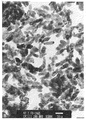
Inを18%含む塩酸溶液200gを純水で2.9Lとし、さらに塩化第二錫を5.4g添加して混合溶液として出発溶液の酸性水溶液を調製しガラスビーカーに仕込んだ。25%NH3水150gを純水1350gで希釈し、このアルカリ溶液を上記酸性水溶液に添加する。まず、はじめに液温20℃の酸性水溶液にアルカリ溶液を17分間添加してpH3に予備中和する。次いで、液温を90℃まで昇温し残りのアルカリ溶液を60分間かけて添加する。最終のpHは7.5であった。これを濾過、脱水、乾燥してSn含有In水酸化物の沈殿を得た。このSn含有In水酸化物のTEM写真を図−1に示す。この水酸化物の長軸径は0.077μm、短軸径は0.028μm、長軸径/短軸径の軸比は2.8であった。
次いで、このSn含有In水酸化物を管状炉に入れ、1.5vol%の水蒸気と0.05vol%のNH3ガスとを含有する窒素ガスの雰囲気中で600℃にて2時間焼成した。得られたSn含有In酸化物のTEM写真を図−2に示す。この得られたSn含有In酸化物粒子は長軸径が0.041μm、短軸径が0.025μm、長軸径/短軸径の軸比が1.64の板状形状の粒子であった。なお、長軸径、短軸径の求め方としては、TEM写真中の50個の粒子の長軸径、短軸径をノギスで実測して、倍率換算しその平均値を求めた。さらに軸比は前記の長軸径と短軸径の比率より算出した。得られた粉体の比表面積をBET1点法にて測定したところ27.5m2/gであった。また、結晶子径Dxは210Åであり、Dx/Dbetは0.68であった。
【0015】
この粉末5gと混合溶剤20g(エタノール:プロパノール=7:3)及び分散剤としてアニオン系界面活性剤を0.25gを遊星ボールミル(フリッチェ製P−5型、容器容量80ml、PSZ0.3mmボール)に入れ、回転数300rpmで30分間回転させて、この分散液にコロイダルシリカとエタノールを加えて、ITO粉末の含有量が2%、シリカ含有量が2%、残部がエタノール及びプロパノールである塗料を作成し、ガラス板にスピンコートした後、200℃で30分間乾燥し、膜厚0.3μmの透明導電性膜を作成した。作成した膜の抵抗値を測定したところ、抵抗値が5KΩ/□であった。また、分光光度計にて透過率を測定したところ透過率は90%(波長540nm)であり、良好な透明導電性膜が得られた。
【0016】
[ 実施例2]
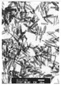
実施例1と同様にして、酸性水溶液、アルカリ溶液を調製した。まず、はじめに液温20℃の酸性水溶液にアルカリ溶液を15分間添加し、pH3.5に予備中和した。次いで、液温を90℃まで昇温し残りのアルカリ溶液を60分間かけて添加する。最終のpHは7.5であった。これを濾過、脱水、乾燥してSn含有In水酸化物を得た。このSn含有In水酸化物のTEM写真を図−3に示す。得られたSn含有In水酸化物粒子は長軸径が0.246μm、短軸径が0.062μm、長軸径/短軸径の軸比は4であった。
次いで、このSn含有In水酸化物を管状炉に入れ、1.5vol%の水蒸気を含有する窒素ガスの雰囲気中で700℃にて2時間焼成した。得られたSn含有In酸化物粒子のTEM写真を図−4に示す。得られたSn含有In酸化物粒子は長軸径が0.075μm、短軸径が0.029μm、長軸径/短軸径の軸比が2.6の針状形状の粒子であった。得られた粉体の比表面積をBET1点法にて測定したところ33m2/gであった。また、Dxは165Åであり、Dx/Dbetは0.64であった。
この粉末を実施例1と同様にしてスピンコートし、膜厚0.3μmの透明導電性膜を作成した。作成した膜の抵抗値を測定したところ、抵抗値が4KΩ/□であった。また、分光光度計にて透過率を測定したところ透過率は90%(波長540nm)であり、良好な透明導電性膜が得られた。
【0017】
[ 比較例1]
実施例1と同様にして、酸性水溶液、アルカリ溶液を調製した。液温35℃の酸性水溶液に60分間かけてアルカリ溶液を添加し、最終のpHが7.5であった。これを濾過、脱水、乾燥してSn含有In水酸化物を得た。このSn含有In水酸化物のTEM写真を図−5に示す。得られたSn含有In水酸化物粒子は長軸径が0.039μm、短軸径が0.032μmの凝集体となっていた。
次いで、このSn含有In水酸化物を管状炉に入れ、1.5vol%の水蒸気と0.05vol%NH3とを含有する窒素ガスの雰囲気中で645℃で2時間焼成した。得られたSn含有In酸化物TEM写真を図−6に示す。この得られたSn含有In酸化物粒子は塊状形状であった。得られた粉体の比表面積をBET1点法にて測定したところ28m2/gであった。また、Dxは260Åであり、Dx/Dbetは0.86であった。
この粉末を実施例1と同様にしてスピンコートし、膜厚0.3μmの透明導電性膜を作成した。作成した膜の抵抗値を測定したところ、抵抗値が20KΩ/□であった。また、分光光度計にて透過率を測定したところ透過率は90%(波長540nm)であり、実施例1、2と異なり、Sn含有In酸化物同士が点接触となり、塗膜抵抗値が上がる結果となった。
【0018】
[ 比較例2]
中和時の液温を50℃とした以外は比較例1と同様にしてSn含有In水酸化物を得た。このSn含有In水酸化物のTEM写真を図−7に示す。得られたSn含有In水酸化物粒子は長軸径が0.215μm、短軸径が0.105μm、軸比が2.1となっていた。
次いで、これを窒素ガス雰囲気中にて700℃で2時間焼成した。焼成後のSn含有In酸化物のTEM写真を図−8に示した。得られたSn含有In酸化物は長軸径が0.270μm、短軸径が0.150μm、軸比が1.8の粗大な粒子となっていた。得られた粉体の比表面積をBET1点法にて測定したところ13.6m2/gであった。また、Dxは270Åであり、Dx/Dbetは0.43であった。
この粉末を実施例1と同様にしてスピンコートし、膜厚0.3μmの導電性膜を作成した。透過率は70%と低く、抵抗値は15KΩ/□と高いものであった。
【0019】
【発明の効果】
本発明によれば、長軸径および短軸径が所定値以下、軸比が所定範囲の針状または板状の形状を有するSn含有In酸化物粒子を得ることができ、この粒子を含有する導電性塗膜は粒子同士の接触面が増加し導電性、透光性とも優れたものであり、ブラウン管の大型化及び表示デバイスの高精細電極用へ塗布方式で対応することができ低コスト化を実現できる。
【図面の簡単な説明】
【図1】実施例1におけるSn含有In水酸化物粒子の透過電子顕微鏡写真である(撮影条件:200.0KV×100K、図中下方の白抜き直線は50nmを示す)。
【図2】実施例1におけるSn含有In酸化物粒子の透過電子顕微鏡写真である(撮影条件:200.0KV×100K、図中下方の白抜き直線は50nmを示す)。
【図3】実施例2におけるSn含有In水酸化物粒子の透過電子顕微鏡写真である(撮影条件:200.0KV×30K、図中下方の白抜き直線は200nmを示す)。
【図4】実施例2におけるSn含有In酸化物粒子の透過電子顕微鏡写真である(撮影条件:200.0KV×100K、図中下方の白抜き直線は50nmを示す)。
【図5】比較例1におけるSn含有In水酸化物粒子の透過電子顕微鏡写真である(撮影条件:200.0KV×100K、図中下方の白抜き直線は50nmを示す)。
【図6】比較例1におけるSn含有In酸化物粒子の透過電子顕微鏡写真である(撮影条件:200.0KV×100K、図中下方の白抜き直線は50nmを示す)。
【図7】比較例2におけるSn含有In水酸化物粒子の透過電子顕微鏡写真である(撮影条件:200.0KV×50K、図中下方の白抜き直線は100nmを示す)。
【図8】比較例2におけるSn含有In酸化物粒子の透過電子顕微鏡写真である(撮影条件:200.0KV×30K、図中下方の白抜き直線は200nmを示す)。[0001]
BACKGROUND OF THE INVENTION
The present invention relates to a Sn-containing In oxide (sometimes referred to as ITO) and a method for producing the same, and further relates to a paint and a conductive coating film using the same.
[0002]
[Prior art]
Sn-containing In oxide is also referred to as ITO, and is used as a transparent conductive film for various display devices, solar cells, and the like because it exhibits translucency for visible light and high conductivity.
As a method for producing a transparent conductive film using ITO, a physical method such as a sputtering method and a coating method in which a particle dispersion or an organic compound is applied are known. Of these, the film formed by the coating method is slightly less conductive than the film formed by a physical method such as sputtering, but can be formed in a large area or a complicated shape without using an expensive apparatus such as a vacuum apparatus. There is a feature of low cost. Furthermore, among these coating methods, the particle dispersion method is widely used as an electromagnetic wave shielding film for a cathode ray tube because it can be formed by a process at a relatively low temperature compared to a method of thermally decomposing an organic compound, and conductivity is obtained. Applications to transparent electrodes of display devices such as EL are also being studied. However, since the coating film by the particle dispersion method is still less conductive than the sputtered film, etc., it cannot be applied to a large-size cathode ray tube or a high-definition electrode of a display device. The appearance of ITO particles that can achieve a coating film that maintains light properties and has improved conductivity is desired.
[0003]
In the conductive coating film, a conductive path is formed by contact between the ITO particles, so that the conductive path is easily obtained (that is, the contact surface between the ITO particles increases). Alternatively, the conductivity can be improved (that is, the resistance can be reduced) by using needle-like or plate-like particles. As an attempt to obtain various particle shapes,
(A) A method for obtaining acicular ITO particles having a major axis length of 5 μm or more and a major axis / minor axis ratio of 5 or more (JP-A-7-232920, JP-A-7-235214)
(B) A method of coating conductive fine particles on strip-shaped titanium oxide particles having a length of 1 to 100 μm, a width of 0.2 to 20 μm, and a thickness of 0.01 to 2 μm (Japanese Patent Laid-Open No. 8-217446)
(C) Method for producing acicular ITO having a major axis of 0.2 to 0.95 [mu] m, a minor axis of 0.02 to 0.1 [mu] m, and an aspect ratio of 4 or more (JP-A-6-80422)
Such manufacturing methods are known. However, with respect to (A), although the obtained ITO particles are large and the resistance value is reduced, there is a problem that optical properties such as transmittance are poor, and particularly, a lot of scattered light is generated and the haze of the coating film increases. Regarding (B), it is strip-shaped and it is considered that a contact point can be obtained, but the particles are large and have the same problems as in (A), and furthermore, the titanium oxide particles having low conductivity are coated with a conductive material. The internal resistance is high and sufficient conductivity cannot be obtained in the coating film. Further, (C) is finer than (A) and its optical characteristics are somewhat improved, but it is larger than half the wavelength of visible light (400 to 700 nm), and the coating film is filled with particles. In this case, scattered light is generated, and there is a problem that sufficient light transmittance of visible light and haze prevention cannot be achieved.
[0004]
[Problems to be solved by the invention]
An object of the present invention is to provide an Sn-containing In oxide having a needle-like or plate-like shape, which is optimal for forming a coating film exhibiting high translucency and conductivity by applying a particle dispersion. It is what.
[0005]
[Means for Solving the Problems]
In order to solve the above-mentioned problems, the present inventors have made the conductive material in the coating film into a Sn-like In oxide particle having a needle-like or plate-like shape with a prescribed size and axial ratio. As a result of earnest research on the idea that it is possible to improve the conductivity by increasing the contact surface between the Sn-containing In oxide particles and to suppress the scattered light, an alkaline aqueous solution containing Sn and In is used. By adding and neutralizing in two or more steps, it was possible to successfully produce a fine Sn-containing In oxide without agglomeration, and to improve the conductivity and suppress the scattered light as compared with the prior art. did it.
[0006]
That is, the present invention firstly includes a Sn-containing In oxide characterized by having a major axis diameter of 0.2 μm or less and a minor axis diameter of 0.1 μm or less and having a needle-like or plate-like shape; 2. The Sn-containing In oxide according to the first aspect, wherein the major axis diameter is 0.1 μm or less and the minor axis diameter is 0.05 μm or less; and third, the major axis diameter / the minor axis diameter The Sn-containing In oxide according to 1 or 2, wherein the ratio is 1.5 to 10; fourth, the Sn-containing In oxide particles according to the first, second, or 3 in a solvent or a solvent containing a resin A coating film characterized by being dispersed therein; fifth, a conductive coating film characterized by containing the Sn-containing In oxide particles according to the first, second or third as a conductive material; The temperature of the pre-neutralized solution obtained by adding alkali to an acidic aqueous solution containing Sn and In is increased, and then the alkali is added. The method for producing a Sn-containing In oxide according to the first, second or third, characterized in that the Sn-containing In hydroxide obtained by adding and neutralizing is calcined; The production method according to 6, wherein the acid in the mixture is HCl, HNO 3 or H 2 SO 4 and the alkali is NH 4 OH, NaOH or KOH; eighth, the pH of the pre-neutralized solution is 2 And the pH of the post-neutralization solution is 7 to 8, wherein the pre-neutralization is performed at a liquid temperature of 45 ° C. or less, and the neutralization is performed The manufacturing method according to 6, 7, or 8 performed at a liquid temperature of 50 ° C. or higher; tenth, in an inert gas containing water vapor or an inert gas containing water vapor and a reducing gas Shape of the Sn-containing In hydroxide particles at 300 to 1000 ° C. The production method according to 6, 7, 8 or 9, which is performed while maintaining anisotropy.
[0007]
DETAILED DESCRIPTION OF THE INVENTION
Sn-containing In oxide particles can be produced by the following steps.
(1) Preparation of raw acid aqueous solution It is preferable to prepare an acidic aqueous solution as a starting solution by further dissolving stannic chloride in an indium chloride aqueous solution in which In is dissolved in hydrochloric acid. The In concentration in the liquid is preferably 2 to 50 g / L, and more preferably 2 to 30 g / L. If it exceeds 50 g / L, the hydroxide particles that are precursors of the oxide are aggregated to suppress acicular or plate-like formation, while if it is less than 2 g / L, only fine massive particles are obtained. The Sn content in the final oxide is preferably 2 to 20 wt% (simply referred to as%) in terms of SnO 2 , and more preferably 5 to 10%. When it is out of the range of 2 to 20%, the conductivity of the oxide is lowered. The acid to be used is not limited to hydrochloric acid (sometimes called HCl), but nitric acid (sometimes called HNO 3 ), sulfuric acid (sometimes called H 2 SO 4 ), and the like.
Further, NH 4 OH (sometimes referred to as ammonia or NH 3 ), NaOH, KOH, or the like is used as the alkali used in the preliminary neutralization step and the neutralization step. However, carbonate-based alkali tends to make the hydroxide particles finely aggregated, and it is difficult to obtain a desired shape. When adding an alkali, it is preferable to use it as a diluted aqueous alkali solution. Further, the amount of alkali added needs to be equivalent to hydrolyze the In and Sn salts in the acidic aqueous solution, and is preferably equal to or higher than the equivalent ratio in order to neutralize excess acid content.
[0008]
(2) Pre-neutralization and neutralization First, when the Sn-containing In hydroxide as a precursor is generated, the alkali solution is added at a liquid temperature of preferably 45 ° C. or lower, more preferably 25 ° C. or lower, preferably at 45 ° C. Thus, it is preferably pre-neutralized to pH 2-4. Further, in the subsequent neutralization, the temperature is raised in 30 minutes to 2 hours and the liquid temperature is preferably raised to 50 ° C. or higher, more preferably 80 to 95 ° C., and the alkali is added, preferably pH 7 to 8 To precipitate Sn-containing In hydroxide, which is filtered, washed and dried.
An acidic aqueous solution containing Sn and In is first formed into fine particle nuclei by pre-neutralization, and then grown as a nucleus in a high-temperature neutralization process to produce needle-like or plate-like hydroxide particles. The shape is controlled by conditions such as the neutralization ratio of pre-neutralization (the ratio of In amount precipitated by pre-neutralization when the total In amount is 1), temperature, pH and the like. In addition, by using different temperature ranges at the time of preliminary neutralization and neutralization, particles having a desired particle size and shape can be generated relatively uniformly. Further, it can be made more uniform by adding an operation such as ripening of fine particle nuclei.
[0009]
(3) Sn-containing In hydroxide The hydroxide thus obtained is a particle larger than the final oxide because it is sintered in the next firing step, and the major axis diameter is 0.05 to 0.3 μm. Needle-like or plate-like particles having an axial diameter of 0.01 to 0.2 μm and an axial ratio of 1.5 to 10 are used.
[0010]
(4) Firing The Sn-containing In hydroxide is calcined, dehydrated and decomposed, and sintered to maintain the shape anisotropy of the hydroxide particles and obtain needle-like or plate-like oxide particles. By this baking, an oxide having oxygen deficiency introduced and enhanced conductivity can be obtained. Oxide particles having electrical conductivity can be obtained even by firing in an oxidizing atmosphere, but the resistance value is an order of magnitude higher than a predetermined resistance value to be obtained.
The firing atmosphere is preferably in an inert gas such as nitrogen containing water vapor, and more preferably also contains a reducing gas such as NH 3 .
The firing temperature is set according to the size, shape, and firing atmosphere gas of the hydroxide, but the higher the temperature, the more water vapor, the stronger the reducing property, the more the sintering, and the anisotropy of the resulting oxide. Lower. The firing temperature is preferably 300 to 1000 ° C, more preferably 300 to 700 ° C. The target oxide particles can be obtained by maintaining the shape anisotropy of the hydroxide particles by firing at the above temperature and atmosphere. However, decomposition of hydroxide is insufficient at temperatures below 300 ° C., and exceeding 1000 ° C. makes it difficult to maintain the shape anisotropy of the hydroxide particles, and aggregation due to interparticle sintering Increases and dispersibility decreases.
Further, the particles after dehydration decomposition of the hydroxide have poor crystallinity, and unless the crystals grow, the conductivity becomes low due to resistance between crystallites in the particles. In order to promote the sintering, it is preferable to add water vapor to the firing atmosphere and to further contain reducing NH 3 or H 2 in order to enhance the conductivity.
[0011]
(5) Sn-containing In oxide particles The oxide particles of the present invention have a major axis diameter of 0.2 μm or less, preferably 0.1 μm or less, and a minor axis diameter of 0.1 μm or less, preferably 0.05 μm or less. In addition, it is a Sn-containing In oxide having a needle-like or plate-like shape, and the axial ratio of the major axis diameter / minor axis diameter is preferably 1.5 to 10, and more preferably 2 to 5.
If the major axis diameter of the Sn-containing In oxide particles exceeds 0.2 μm, scattering of visible light occurs and optical characteristics such as transmittance deteriorate, so that it is 0.2 μm or less. In particular, when the major axis diameter is 0.1 μm or less, the scattering of visible light is further suppressed. Further, when the minor axis diameter exceeds 0.1 μm, the contact surface between the particles is low and the coating film conductivity is low. Particularly when the thickness is 0.05 μm or less, the coating film conductivity is further improved. Furthermore, when the axial ratio of the major axis diameter / minor axis diameter is out of the range of 1.5 to 10, the conductivity, dispersibility, and intracrystalline crystallinity are deteriorated. Effects such as a decrease in resistance value cannot be obtained.
The preferable crystallite diameter Dx calculated from the half width of the (222) plane by X-ray diffraction is 150 mm or more, and the ratio Dx / Dbet to the spherical equivalent diameter Dbet obtained from the specific surface area is 0.45 or more. It is considered that the resistance as particles decreases as the number of crystallites in the particles decreases in the observation with a microscope (sometimes referred to as TEM).
[0012]
(6) Paint, conductive coating The above ITO particles are dispersed in a solvent to form a paint, which is then applied to volatilize the solvent, and the film is fixed to form a film with high translucency and low resistance. A coating film can be obtained.
A conventional method can be used as a coating method, and an organic solvent such as alcohol, ketone, or ether is added as a solvent, a surfactant, a coupling agent or the like is added as a dispersing agent, and a dispersing device such as a bead mill is used. Disperse. Further, a binder (organic or inorganic) serving as a binder may be added, or a binder may be formed and fixed after forming the ITO paint film.
[0013]
【Example】
EXAMPLES The present invention will be further described below with reference to examples and comparative examples, but the technical scope of the present invention is not limited to these examples.
[0014]
[Example 1]
200 g of a hydrochloric acid solution containing 18% In was made 2.9 L with pure water, and further 5.4 g of stannic chloride was added to prepare an acidic aqueous solution as a mixed solution, which was charged into a glass beaker. 150 g of 25% NH 3 water is diluted with 1350 g of pure water, and this alkaline solution is added to the acidic aqueous solution. First, an alkaline solution is added to an acidic aqueous solution having a liquid temperature of 20 ° C. for 17 minutes to pre-neutralize to pH 3. Next, the liquid temperature is raised to 90 ° C., and the remaining alkaline solution is added over 60 minutes. The final pH was 7.5. This was filtered, dehydrated and dried to obtain a precipitate of Sn-containing In hydroxide. A TEM photograph of this Sn-containing In hydroxide is shown in FIG. This hydroxide had a major axis diameter of 0.077 μm, a minor axis diameter of 0.028 μm, and a major axis / minor axis ratio of 2.8.
Next, this Sn-containing In hydroxide was put in a tube furnace and baked at 600 ° C. for 2 hours in an atmosphere of nitrogen gas containing 1.5 vol% steam and 0.05 vol% NH 3 gas. A TEM photograph of the obtained Sn-containing In oxide is shown in FIG. The obtained Sn-containing In oxide particles were plate-like particles having a major axis diameter of 0.041 μm, a minor axis diameter of 0.025 μm, and a major axis / minor axis ratio of 1.64. . The major axis diameter and minor axis diameter were determined by measuring the major axis diameter and minor axis diameter of 50 particles in the TEM photograph with calipers, and converting the magnification to obtain the average value. Furthermore, the axial ratio was calculated from the ratio of the major axis diameter to the minor axis diameter. It was 27.5 m < 2 > / g when the specific surface area of the obtained powder was measured by the BET 1 point method. The crystallite diameter Dx was 210 mm, and Dx / Dbet was 0.68.
[0015]
5 g of this powder, 20 g of a mixed solvent (ethanol: propanol = 7: 3), and 0.25 g of an anionic surfactant as a dispersing agent were put on a planetary ball mill (Frichche P-5 type, container capacity 80 ml, PSZ 0.3 mm ball). Add the colloidal silica and ethanol to this dispersion for 30 minutes at a rotational speed of 300 rpm to create a paint with an ITO powder content of 2%, a silica content of 2%, and the balance of ethanol and propanol. And after spin-coating on a glass plate, it dried at 200 degreeC for 30 minute (s), and produced the transparent conductive film with a film thickness of 0.3 micrometer. When the resistance value of the prepared film was measured, the resistance value was 5 KΩ / □. When the transmittance was measured with a spectrophotometer, the transmittance was 90% (wavelength 540 nm), and a good transparent conductive film was obtained.
[0016]
[Example 2]
In the same manner as in Example 1, an acidic aqueous solution and an alkaline solution were prepared. First, an alkaline solution was first added to an acidic aqueous solution having a liquid temperature of 20 ° C. for 15 minutes, and pre-neutralized to pH 3.5. Next, the liquid temperature is raised to 90 ° C., and the remaining alkaline solution is added over 60 minutes. The final pH was 7.5. This was filtered, dehydrated and dried to obtain Sn-containing In hydroxide. A TEM photograph of this Sn-containing In hydroxide is shown in FIG. The obtained Sn-containing In hydroxide particles had a major axis diameter of 0.246 μm, a minor axis diameter of 0.062 μm, and a major axis / minor axis ratio of 4.
Next, this Sn-containing In hydroxide was put in a tubular furnace and baked at 700 ° C. for 2 hours in an atmosphere of nitrogen gas containing 1.5 vol% of water vapor. A TEM photograph of the obtained Sn-containing In oxide particles is shown in FIG. The obtained Sn-containing In oxide particles were needle-like particles having a major axis diameter of 0.075 μm, a minor axis diameter of 0.029 μm, and a major axis / minor axis ratio of 2.6. It was 33 m < 2 > / g when the specific surface area of the obtained powder was measured by the BET 1 point method. Moreover, Dx was 165cm and Dx / Dbet was 0.64.
This powder was spin-coated in the same manner as in Example 1 to produce a transparent conductive film having a thickness of 0.3 μm. When the resistance value of the prepared film was measured, the resistance value was 4 KΩ / □. When the transmittance was measured with a spectrophotometer, the transmittance was 90% (wavelength 540 nm), and a good transparent conductive film was obtained.
[0017]
[Comparative Example 1]
In the same manner as in Example 1, an acidic aqueous solution and an alkaline solution were prepared. The alkaline solution was added to the acidic aqueous solution with a liquid temperature of 35 ° C. over 60 minutes, and the final pH was 7.5. This was filtered, dehydrated and dried to obtain Sn-containing In hydroxide. A TEM photograph of this Sn-containing In hydroxide is shown in FIG. The obtained Sn-containing In hydroxide particles were aggregates having a major axis diameter of 0.039 μm and a minor axis diameter of 0.032 μm.
Next, this Sn-containing In hydroxide was put in a tube furnace and baked at 645 ° C. for 2 hours in an atmosphere of nitrogen gas containing 1.5 vol% steam and 0.05 vol% NH 3 . The obtained Sn-containing In oxide TEM photograph is shown in FIG. The obtained Sn-containing In oxide particles had a lump shape. It was 28 m < 2 > / g when the specific surface area of the obtained powder was measured by the BET 1 point method. Moreover, Dx was 260 mm and Dx / Dbet was 0.86.
This powder was spin-coated in the same manner as in Example 1 to produce a transparent conductive film having a thickness of 0.3 μm. When the resistance value of the prepared film was measured, the resistance value was 20 KΩ / □. Further, when the transmittance was measured with a spectrophotometer, the transmittance was 90% (wavelength 540 nm). Unlike Examples 1 and 2, Sn-containing In oxides were in point contact with each other, and the coating film resistance value was increased. As a result.
[0018]
[Comparative Example 2]
An Sn-containing In hydroxide was obtained in the same manner as in Comparative Example 1 except that the liquid temperature during neutralization was 50 ° C. A TEM photograph of this Sn-containing In hydroxide is shown in FIG. The obtained Sn-containing In hydroxide particles had a major axis diameter of 0.215 μm, a minor axis diameter of 0.105 μm, and an axial ratio of 2.1.
Next, this was fired at 700 ° C. for 2 hours in a nitrogen gas atmosphere. A TEM photograph of the Sn-containing In oxide after firing is shown in FIG. The obtained Sn-containing In oxide was coarse particles having a major axis diameter of 0.270 μm, a minor axis diameter of 0.150 μm, and an axial ratio of 1.8. It was 13.6 m < 2 > / g when the specific surface area of the obtained powder was measured by the BET 1 point method. Dx was 270 mm and Dx / Dbet was 0.43.
This powder was spin-coated in the same manner as in Example 1 to produce a conductive film having a thickness of 0.3 μm. The transmittance was as low as 70%, and the resistance value was as high as 15 KΩ / □.
[0019]
【Effect of the invention】
According to the present invention, Sn-containing In oxide particles having a needle-like or plate-like shape having a major axis diameter and a minor axis diameter of a predetermined value or less and an axial ratio in a predetermined range can be obtained, and contain these particles. The conductive coating film has an increased contact surface between particles and is excellent in both conductivity and translucency. It can be applied to large-sized cathode-ray tubes and high-definition electrodes for display devices, reducing costs. Can be realized.
[Brief description of the drawings]
FIG. 1 is a transmission electron micrograph of Sn-containing In hydroxide particles in Example 1 (photographing conditions: 200.0 KV × 100 K, the white line in the lower part of the figure indicates 50 nm).
FIG. 2 is a transmission electron micrograph of Sn-containing In oxide particles in Example 1 (photographing conditions: 200.0 KV × 100 K, the white line below in the figure indicates 50 nm).
FIG. 3 is a transmission electron micrograph of Sn-containing In hydroxide particles in Example 2 (photographing conditions: 200.0 KV × 30 K, and the lower white line in the figure indicates 200 nm).
FIG. 4 is a transmission electron micrograph of Sn-containing In oxide particles in Example 2 (photographing conditions: 200.0 KV × 100 K, and the lower white line in the figure indicates 50 nm).
FIG. 5 is a transmission electron micrograph of Sn-containing In hydroxide particles in Comparative Example 1 (photographing conditions: 200.0 KV × 100 K, the white line in the lower part of the figure indicates 50 nm).
FIG. 6 is a transmission electron micrograph of Sn-containing In oxide particles in Comparative Example 1 (photographing conditions: 200.0 KV × 100 K, the white line below in the figure indicates 50 nm).
FIG. 7 is a transmission electron micrograph of Sn-containing In hydroxide particles in Comparative Example 2 (photographing conditions: 200.0 KV × 50 K, and the lower white line in the figure indicates 100 nm).
FIG. 8 is a transmission electron micrograph of Sn-containing In oxide particles in Comparative Example 2 (photographing conditions: 200.0 KV × 30 K, and the lower white line in the figure indicates 200 nm).
Claims (10)
Priority Applications (4)
| Application Number | Priority Date | Filing Date | Title |
|---|---|---|---|
| JP2001245701A JP4982691B2 (en) | 2001-08-13 | 2001-08-13 | Sn-containing In oxide, method for producing the same, paint using the same, and conductive coating film |
| US10/108,618 US6908574B2 (en) | 2001-08-13 | 2002-03-28 | Tin-containing indium oxides, a process for producing them, a coating solution using them and electrically conductive coatings formed of them |
| TW091106612A TWI311983B (en) | 2001-08-13 | 2002-04-02 | Tin-containing indium oxides, a process for producing them, a coating solution using them and electrically conductive coatings formed of them |
| KR1020020031689A KR100670621B1 (en) | 2001-08-13 | 2002-06-05 | Tin-containing indium oxides, a process for producing them, a coating solution using them and electrically conductive coatings formed of them |
Applications Claiming Priority (1)
| Application Number | Priority Date | Filing Date | Title |
|---|---|---|---|
| JP2001245701A JP4982691B2 (en) | 2001-08-13 | 2001-08-13 | Sn-containing In oxide, method for producing the same, paint using the same, and conductive coating film |
Publications (2)
| Publication Number | Publication Date |
|---|---|
| JP2003054949A JP2003054949A (en) | 2003-02-26 |
| JP4982691B2 true JP4982691B2 (en) | 2012-07-25 |
Family
ID=19075400
Family Applications (1)
| Application Number | Title | Priority Date | Filing Date |
|---|---|---|---|
| JP2001245701A Expired - Lifetime JP4982691B2 (en) | 2001-08-13 | 2001-08-13 | Sn-containing In oxide, method for producing the same, paint using the same, and conductive coating film |
Country Status (1)
| Country | Link |
|---|---|
| JP (1) | JP4982691B2 (en) |
Families Citing this family (9)
| Publication number | Priority date | Publication date | Assignee | Title |
|---|---|---|---|---|
| JP5082132B2 (en) * | 2005-01-19 | 2012-11-28 | 三菱マテリアル株式会社 | Indium tin oxide precursor, indium tin oxide film thereof, and manufacturing method thereof |
| US20070023765A1 (en) * | 2005-07-29 | 2007-02-01 | Thomas Alan C | Acicular ITO for LED array |
| JP4617506B2 (en) * | 2006-03-24 | 2011-01-26 | Dowaエレクトロニクス株式会社 | ITO powder and manufacturing method thereof, coating material for ITO conductive film, and transparent conductive film |
| JP4686776B2 (en) * | 2006-08-28 | 2011-05-25 | Dowaエレクトロニクス株式会社 | ITO powder and manufacturing method thereof, coating material for ITO conductive film, and transparent conductive film |
| JP5153541B2 (en) * | 2008-09-24 | 2013-02-27 | Dowaエレクトロニクス株式会社 | Method for producing Sn-containing In oxide and method for producing conductive paint |
| JP5486751B2 (en) * | 2009-09-18 | 2014-05-07 | 三菱マテリアル株式会社 | Rod-shaped indium tin oxide powder and method for producing the same |
| JP5486752B2 (en) * | 2009-09-18 | 2014-05-07 | 三菱マテリアル株式会社 | Heat ray shielding composition containing rod-shaped indium tin oxide powder and method for producing the same |
| JP6122304B2 (en) * | 2013-02-12 | 2017-04-26 | 三菱マテリアル電子化成株式会社 | Method for producing indium tin oxide powder |
| WO2014168245A1 (en) * | 2013-04-12 | 2014-10-16 | 三菱マテリアル株式会社 | Indium tin oxide powder, dispersion of same or coating material comprising same, transparent electrically conductive film, and method for producing indium tin oxide powder |
Family Cites Families (2)
| Publication number | Priority date | Publication date | Assignee | Title |
|---|---|---|---|---|
| JP3251066B2 (en) * | 1992-08-31 | 2002-01-28 | 富士チタン工業株式会社 | Method for producing acicular conductive fine powder |
| JPH08302246A (en) * | 1995-05-09 | 1996-11-19 | Sumitomo Osaka Cement Co Ltd | Coating for forming transparent membrane having high electroconductivity and high membrane strength, formation of transparent membrane having high electroconductivity and membrane, strength, and cathode ray tube |
-
2001
- 2001-08-13 JP JP2001245701A patent/JP4982691B2/en not_active Expired - Lifetime
Also Published As
| Publication number | Publication date |
|---|---|
| JP2003054949A (en) | 2003-02-26 |
Similar Documents
| Publication | Publication Date | Title |
|---|---|---|
| JP4134314B2 (en) | Method for producing conductive powder | |
| TWI640479B (en) | Mathod for manufacturing composite-tungsten-oxide nanoparticles | |
| JP5618229B2 (en) | ITO powder, method for producing ITO particles, coating for transparent conductive material and transparent conductive film | |
| JP4018974B2 (en) | Tin oxide powder, method for producing the same, and method for producing high-density indium tin oxide target using the same | |
| KR100670621B1 (en) | Tin-containing indium oxides, a process for producing them, a coating solution using them and electrically conductive coatings formed of them | |
| JP2009084122A (en) | Ito powder and its manufacturing method, coating material for transparent electroconductive material, and transparent electroconductive film | |
| EP2305608B1 (en) | Process for producing ito particles | |
| WO2023098706A1 (en) | Zinc-doped indium oxide powder, sputtering target material, and preparation methods therefor | |
| JP4982691B2 (en) | Sn-containing In oxide, method for producing the same, paint using the same, and conductive coating film | |
| JP4617499B2 (en) | ITO powder and manufacturing method thereof, coating material for transparent conductive material, and transparent conductive film | |
| JP3936655B2 (en) | Indium oxide powder, method for producing the same, and method for producing high-density indium tin oxide target using the same | |
| JP5233007B2 (en) | Paint for transparent conductive material and method for producing transparent conductive film | |
| WO2004089829A1 (en) | Composite indium oxide particle, method for producing same, conductive coating material, conductive coating film, and conductive sheet | |
| JP2008110915A (en) | Tin-doped indium oxide powder | |
| JP4134313B2 (en) | Method for producing conductive powder | |
| JPH04325415A (en) | Indium hydroxide and oxide | |
| JP5070554B2 (en) | ITO powder, transparent conductive film and method for forming the same | |
| CN109502643B (en) | Boron-magnesium co-doped VO2Powder and preparation method and application thereof | |
| JPH1017324A (en) | Production of indium oxide power | |
| JP3324164B2 (en) | Indium oxide powder, method for producing the same, and method for producing ITO sintered body | |
| JP6952051B2 (en) | Method for manufacturing infrared shielding material and tin oxide particles | |
| JP4251448B2 (en) | Aluminum-substituted tin-containing indium oxide particles and method for producing the same, and conductive paint, conductive coating film and conductive sheet using the particles | |
| KR100455280B1 (en) | Method of preparing indium tin oxide(ITO) | |
| KR101117309B1 (en) | Method for producing indium tin oxides fine powder | |
| KR101287804B1 (en) | Method of manufacturing indium tin oxide target |
Legal Events
| Date | Code | Title | Description |
|---|---|---|---|
| RD02 | Notification of acceptance of power of attorney |
Free format text: JAPANESE INTERMEDIATE CODE: A7422 Effective date: 20040206 |
|
| RD04 | Notification of resignation of power of attorney |
Free format text: JAPANESE INTERMEDIATE CODE: A7424 Effective date: 20040318 |
|
| A621 | Written request for application examination |
Free format text: JAPANESE INTERMEDIATE CODE: A621 Effective date: 20080625 |
|
| A977 | Report on retrieval |
Free format text: JAPANESE INTERMEDIATE CODE: A971007 Effective date: 20100401 |
|
| A131 | Notification of reasons for refusal |
Free format text: JAPANESE INTERMEDIATE CODE: A131 Effective date: 20111220 |
|
| A521 | Written amendment |
Free format text: JAPANESE INTERMEDIATE CODE: A523 Effective date: 20120216 |
|
| TRDD | Decision of grant or rejection written | ||
| A01 | Written decision to grant a patent or to grant a registration (utility model) |
Free format text: JAPANESE INTERMEDIATE CODE: A01 Effective date: 20120306 |
|
| A01 | Written decision to grant a patent or to grant a registration (utility model) |
Free format text: JAPANESE INTERMEDIATE CODE: A01 |
|
| A521 | Written amendment |
Free format text: JAPANESE INTERMEDIATE CODE: A821 Effective date: 20120321 |
|
| A711 | Notification of change in applicant |
Free format text: JAPANESE INTERMEDIATE CODE: A712 Effective date: 20120321 |
|
| A61 | First payment of annual fees (during grant procedure) |
Free format text: JAPANESE INTERMEDIATE CODE: A61 Effective date: 20120321 |
|
| A521 | Written amendment |
Free format text: JAPANESE INTERMEDIATE CODE: A821 Effective date: 20120321 |
|
| R150 | Certificate of patent or registration of utility model |
Ref document number: 4982691 Country of ref document: JP Free format text: JAPANESE INTERMEDIATE CODE: R150 Free format text: JAPANESE INTERMEDIATE CODE: R150 |
|
| FPAY | Renewal fee payment (event date is renewal date of database) |
Free format text: PAYMENT UNTIL: 20150511 Year of fee payment: 3 |
|
| R250 | Receipt of annual fees |
Free format text: JAPANESE INTERMEDIATE CODE: R250 |
|
| R250 | Receipt of annual fees |
Free format text: JAPANESE INTERMEDIATE CODE: R250 |
|
| R250 | Receipt of annual fees |
Free format text: JAPANESE INTERMEDIATE CODE: R250 |
|
| R250 | Receipt of annual fees |
Free format text: JAPANESE INTERMEDIATE CODE: R250 |
|
| R250 | Receipt of annual fees |
Free format text: JAPANESE INTERMEDIATE CODE: R250 |
|
| R250 | Receipt of annual fees |
Free format text: JAPANESE INTERMEDIATE CODE: R250 |
|
| R250 | Receipt of annual fees |
Free format text: JAPANESE INTERMEDIATE CODE: R250 |
|
| EXPY | Cancellation because of completion of term |