JP4980504B2 - Lubricating oil supply facility and lubricating oil supplying method - Google Patents
Lubricating oil supply facility and lubricating oil supplying method Download PDFInfo
- Publication number
- JP4980504B2 JP4980504B2 JP2012506263A JP2012506263A JP4980504B2 JP 4980504 B2 JP4980504 B2 JP 4980504B2 JP 2012506263 A JP2012506263 A JP 2012506263A JP 2012506263 A JP2012506263 A JP 2012506263A JP 4980504 B2 JP4980504 B2 JP 4980504B2
- Authority
- JP
- Japan
- Prior art keywords
- lubricating oil
- spray nozzle
- amount
- oil supply
- rolling roll
- Prior art date
- Legal status (The legal status is an assumption and is not a legal conclusion. Google has not performed a legal analysis and makes no representation as to the accuracy of the status listed.)
- Active
Links
Images


Classifications
-
- B—PERFORMING OPERATIONS; TRANSPORTING
- B05—SPRAYING OR ATOMISING IN GENERAL; APPLYING FLUENT MATERIALS TO SURFACES, IN GENERAL
- B05B—SPRAYING APPARATUS; ATOMISING APPARATUS; NOZZLES
- B05B12/00—Arrangements for controlling delivery; Arrangements for controlling the spray area
- B05B12/08—Arrangements for controlling delivery; Arrangements for controlling the spray area responsive to condition of liquid or other fluent material to be discharged, of ambient medium or of target ; responsive to condition of spray devices or of supply means, e.g. pipes, pumps or their drive means
- B05B12/084—Arrangements for controlling delivery; Arrangements for controlling the spray area responsive to condition of liquid or other fluent material to be discharged, of ambient medium or of target ; responsive to condition of spray devices or of supply means, e.g. pipes, pumps or their drive means responsive to condition of liquid or other fluent material already sprayed on the target, e.g. coating thickness, weight or pattern
-
- B—PERFORMING OPERATIONS; TRANSPORTING
- B05—SPRAYING OR ATOMISING IN GENERAL; APPLYING FLUENT MATERIALS TO SURFACES, IN GENERAL
- B05B—SPRAYING APPARATUS; ATOMISING APPARATUS; NOZZLES
- B05B12/00—Arrangements for controlling delivery; Arrangements for controlling the spray area
- B05B12/08—Arrangements for controlling delivery; Arrangements for controlling the spray area responsive to condition of liquid or other fluent material to be discharged, of ambient medium or of target ; responsive to condition of spray devices or of supply means, e.g. pipes, pumps or their drive means
-
- B—PERFORMING OPERATIONS; TRANSPORTING
- B05—SPRAYING OR ATOMISING IN GENERAL; APPLYING FLUENT MATERIALS TO SURFACES, IN GENERAL
- B05D—PROCESSES FOR APPLYING FLUENT MATERIALS TO SURFACES, IN GENERAL
- B05D3/00—Pretreatment of surfaces to which liquids or other fluent materials are to be applied; After-treatment of applied coatings, e.g. intermediate treating of an applied coating preparatory to subsequent applications of liquids or other fluent materials
-
- B—PERFORMING OPERATIONS; TRANSPORTING
- B21—MECHANICAL METAL-WORKING WITHOUT ESSENTIALLY REMOVING MATERIAL; PUNCHING METAL
- B21B—ROLLING OF METAL
- B21B27/00—Rolls, roll alloys or roll fabrication; Lubricating, cooling or heating rolls while in use
- B21B27/06—Lubricating, cooling or heating rolls
- B21B27/10—Lubricating, cooling or heating rolls externally
-
- F—MECHANICAL ENGINEERING; LIGHTING; HEATING; WEAPONS; BLASTING
- F16—ENGINEERING ELEMENTS AND UNITS; GENERAL MEASURES FOR PRODUCING AND MAINTAINING EFFECTIVE FUNCTIONING OF MACHINES OR INSTALLATIONS; THERMAL INSULATION IN GENERAL
- F16N—LUBRICATING
- F16N7/00—Arrangements for supplying oil or unspecified lubricant from a stationary reservoir or the equivalent in or on the machine or member to be lubricated
- F16N7/30—Arrangements for supplying oil or unspecified lubricant from a stationary reservoir or the equivalent in or on the machine or member to be lubricated the oil being fed or carried along by another fluid
- F16N7/32—Mist lubrication
- F16N7/34—Atomising devices for oil
-
- B—PERFORMING OPERATIONS; TRANSPORTING
- B21—MECHANICAL METAL-WORKING WITHOUT ESSENTIALLY REMOVING MATERIAL; PUNCHING METAL
- B21B—ROLLING OF METAL
- B21B2267/00—Roll parameters
- B21B2267/10—Roughness of roll surface
-
- B—PERFORMING OPERATIONS; TRANSPORTING
- B21—MECHANICAL METAL-WORKING WITHOUT ESSENTIALLY REMOVING MATERIAL; PUNCHING METAL
- B21B—ROLLING OF METAL
- B21B37/00—Control devices or methods specially adapted for metal-rolling mills or the work produced thereby
- B21B37/28—Control of flatness or profile during rolling of strip, sheets or plates
- B21B37/30—Control of flatness or profile during rolling of strip, sheets or plates using roll camber control
- B21B37/32—Control of flatness or profile during rolling of strip, sheets or plates using roll camber control by cooling, heating or lubricating the rolls
Abstract
Description
本発明は、薄板鋼帯や厚板などの鉄鋼製品の製造プロセスにおける圧延工程、とりわけ熱間圧延工程において使用される潤滑油の供給設備ならびに供給方法に関する。 The present invention relates to a lubricating oil supply facility and a supply method used in a rolling process, particularly a hot rolling process, in a manufacturing process of steel products such as thin steel strips and thick plates.
薄板鋼帯や厚板等の鉄鋼製品の製造プロセスにおける熱間圧延工程では、加工工具として使用される圧延ロールに対する負荷の軽減、摩耗や焼付きの抑制、それに伴って生じる疵の発生を低減し製品の良好な表面品質を確保するなど、種々の目的で潤滑圧延が実施されている。 In the hot rolling process in the manufacturing process of steel products such as thin steel strip and thick steel plate, the load on the rolling roll used as a processing tool is reduced, the wear and seizure are suppressed, and the occurrence of wrinkles is reduced. Lubrication rolling is carried out for various purposes such as ensuring good surface quality of products.
熱間圧延工程では、主として、ウォーターインジェクション法により水と潤滑油のエマルション状態の混合液をロールに噴射して供給する方法(例えば、非特許文献1を参照)や、グリースなどの半固体状の潤滑剤をエアー等の気体で吹き飛ばしてロールに付着させる方法などが実施されている(例えば、特許文献1を参照)。 In the hot rolling process, mainly a method of injecting and supplying a mixed liquid in an emulsion state of water and lubricating oil to a roll by a water injection method (for example, see Non-Patent Document 1) or a semi-solid state such as grease A method in which a lubricant is blown off with a gas such as air and adhered to a roll has been implemented (see, for example, Patent Document 1).
それ以外の潤滑方法として、ワックスに黒鉛などの固体潤滑剤を混合させた固形潤滑剤を直接ロールに押し付ける方法(例えば、特許文献2を参照)や、コロイド溶液に種々の添加剤を混合させた非油系潤滑剤をロールもしくはロールバイトに噴射する方法なども知られている。 As other lubrication methods, a solid lubricant in which a solid lubricant such as graphite is mixed with wax is pressed directly onto a roll (see, for example, Patent Document 2), or various additives are mixed into a colloid solution. A method of spraying a non-oil based lubricant onto a roll or a roll bite is also known.
また、近年、水を使わない潤滑油の供給方法として、半固体状のグリースではなく、ウォーターインジェクション法で使用される液体の潤滑油を霧状もしくは粒状にして不燃性ガスと共にロールに噴射供給する方法が提案されている(特許文献3、以下、本法をガスアトマイズ法と呼ぶ)。この方法によれば、少量の潤滑油供給量で大きな摩擦係数低減効果が得られる。さらに、薄板鋼帯の熱間圧延においてガスアトマイズ法を使用するための潤滑設備ならびに潤滑方法も提案されている(例えば、特許文献4を参照)。
In recent years, as a method of supplying lubricating oil that does not use water, liquid lubricating oil used in the water injection method is sprayed and supplied to a roll together with a non-combustible gas in the form of a mist or granule instead of a semi-solid grease. A method has been proposed (
一方、圧延中に必要な部分に十分な潤滑油を供給するために、通常、圧延機には潤滑油供給用の噴霧ノズルが複数設置されている。薄板鋼帯の熱間圧延機には、特許文献1や特許文献4に例示されているように、板幅方向に複数の噴霧ノズルを並べて構成された潤滑ヘッダーが設けられている。このように構成された潤滑ヘッダーにより、ロールと鋼材とが接触する通材部分全域に潤滑油が供給できるようになっている。この潤滑ヘッダーは、圧延機の大きさによって異なるが、ほぼ等間隔で設置された噴霧ノズルを2個以上有し、必要に応じて使用する噴霧ノズルを選択できるような機構を備えている。
On the other hand, in order to supply sufficient lubricating oil to a necessary portion during rolling, a rolling mill is usually provided with a plurality of spray nozzles for supplying lubricating oil. As illustrated in
このような潤滑ヘッダーは、通常、上下のワークロールやバックアップロールに対して、それぞれ1基ずつ設置される。しかしながら、それぞれの圧延プロセスの操業条件によっては、上下のワークロールやバックアップロールのいずれかにだけ設置される場合もある。いずれの場合においても、このような潤滑ヘッダーを使用して潤滑圧延を実施する場合、1基の圧延機において1パスあたり少なくとも2個の噴霧ノズルを使用して潤滑油を供給しているのが現状である。 One such lubricating header is usually installed for each of the upper and lower work rolls and the backup roll. However, depending on the operating conditions of each rolling process, it may be installed only on either the upper or lower work roll or backup roll. In any case, when lubrication rolling is performed using such a lubrication header, lubricating oil is supplied using at least two spray nozzles per pass in one rolling mill. Currently.
噴霧ノズルに潤滑油を送出する設備については、ウォーターインジェクション法では、図1に示すように、水と潤滑油とを別々のポンプにより、すなわち、水送出用ポンプ装置3´と潤滑油送出用ポンプ装置3とにより、インジェクター8と呼ばれる水と潤滑油との混合器へ供給される。このときの水及び潤滑油の供給量はインジェクター8で生成されるエマルションが所定の濃度になるように設定される。インジェクター8で生成された所定濃度のエマルションは、インジェクター8から噴霧ノズル1´までの間の分岐した配管を介して、複数の噴霧ノズル1´に供給される。
As for the equipment for sending the lubricating oil to the spray nozzle, in the water injection method, as shown in FIG. 1, water and lubricating oil are separately pumped, that is, the water sending pump device 3 'and the lubricating oil sending pump. The
エマルションの潤滑油の濃度は、薄板鋼帯の熱間圧延で0.2〜1体積%程度であり、エマルション全体の供給量は1パスあたり毎分数リットル〜数十リットルに達する。 The concentration of the lubricating oil in the emulsion is about 0.2 to 1% by volume in hot rolling of a thin steel strip, and the supply amount of the whole emulsion reaches several liters to several tens of liters per pass.
このような大量のエマルションを供給するには、ある程度の圧力をかけて噴霧ノズルから噴射しなければならないので、配管内のエマルション送出速度が大きく、エマルションが水と潤滑油とに分離する時間的余裕がないので、各噴霧ノズルに比較的均等にほぼ同量のエマルションが送出されロールに噴射される。したがって、ウォーターインジェクション法の場合、配管の取り回しの簡便さから、上ロール用および下ロール用の2セットのポンプ装置を備えた潤滑油供給設備が常用されており、1セットのポンプ装置によって2本以上の噴霧ノズルにエマルションを供給している。 In order to supply such a large amount of emulsion, a certain amount of pressure must be applied and sprayed from the spray nozzle, so the emulsion delivery speed in the pipe is large, and there is a time margin for separating the emulsion into water and lubricating oil. Therefore, the same amount of emulsion is delivered relatively uniformly to each spray nozzle and sprayed onto the roll. Therefore, in the case of the water injection method, a lubricating oil supply facility having two sets of pump devices for upper rolls and lower rolls is commonly used for the convenience of piping, and two sets are provided by one set of pump devices. The emulsion is supplied to the above spray nozzles.
ガスアトマイズ法に関しては、噴霧ノズルの内部に潤滑油とガスとが混合される混合室が備えられた、いわゆる内部混合型の2流体噴霧ノズルを配設した潤滑ヘッダーを使った潤滑油供給設備および潤滑油供給方法が特許文献4に開示されている。この潤滑油供給設備および潤滑油供給方法では、できるだけ潤滑油を加圧せずに噴霧ノズルに供給し、0.5bar(0.05MPa)未満のガスによって潤滑油を粒状化ないしは霧状化して噴霧ノズルから噴霧している。
As for the gas atomizing method, a lubricating oil supply facility using a lubricating header provided with a so-called internal mixing type two-fluid spray nozzle provided with a mixing chamber in which lubricating oil and gas are mixed inside the spray nozzle, and lubrication An oil supply method is disclosed in
特許文献6には、ガスアトマイズ法で潤滑油を粒状化ないしは霧状化して噴霧ノズルから噴射する際に、ロールに付着しない浮遊ミストが発生しても、その飛散を防止するようにした潤滑油供給方法および潤滑油供給設備が開示されている。特許文献6に記載の設備では、潤滑油を噴射する噴霧ノズルの流路の外側に副ノズルとしてエアー噴射機構が設けられている。潤滑油の噴射時には、エアー噴射機構からエアーを吹き付けることでエアーの壁をつくり、これにより浮遊ミストの飛散を抑えるようにしている。
ところで、金属材料の圧延、とりわけ薄板鋼板の熱間圧延においては、圧延ロールの軸方向に対して不均一な摩耗や肌荒れが発生する。しかしながら、ウォーターインジェクション法を用いた場合、前述したように多量の潤滑油をロールに供給することが必要になるため、圧延ロールの軸方向において局所的に潤滑油の供給量を調整することは困難であり、軸方向に不均一な摩耗や肌荒れを抑制することはできない。 By the way, in the rolling of a metal material, especially in the hot rolling of a thin steel plate, uneven wear and rough surface are generated in the axial direction of the rolling roll. However, when the water injection method is used, it is necessary to supply a large amount of lubricating oil to the roll as described above, so it is difficult to locally adjust the amount of lubricating oil supplied in the axial direction of the rolling roll. It is not possible to suppress uneven wear and rough skin in the axial direction.
また、特許文献4に記載のガスアトマイズ法を用いた方法では、潤滑油ディストリビューターから各噴霧ノズルに潤滑油を供給しており、基本的に各噴霧ノズルから同量の潤滑油を供給している。また、圧延ロールの軸方向において局所的に潤滑油の供給量を調整することは考慮されておらず、軸方向に不均一な摩耗や肌荒れを抑制することはできない。
Moreover, in the method using the gas atomizing method described in
そこで、本発明の目的は、圧延ロールの軸方向において、潤滑油の供給量を局所的に調整することで軸方向に不均一な摩耗や肌荒れを効果的に抑制することができる潤滑油供給設備および潤滑油供給方法を提供することにある。 Accordingly, an object of the present invention is to provide a lubricating oil supply facility that can effectively suppress uneven wear and rough skin in the axial direction by locally adjusting the supply amount of the lubricating oil in the axial direction of the rolling roll. And providing a lubricating oil supply method.
上記課題を潤滑油のガスアトマイズ法での供給により解決するために、本発明者らは鋭意検討した結果、以下の知見を得た。
・圧延ロール表面の不均一摩耗、肌荒れは、被圧延材である鋼板の幅方向端部近傍が接触するロール表面付近に発生しやすいこと。
・したがって、潤滑油の噴霧量を、鋼板の端部の接触部分近傍に相対的に多く、鋼板の中央部に相対的に少なく配分することを基本的配分パターンとすることで、効率的にロールの不均一摩耗や肌荒れを回避することができること。In order to solve the above problems by supplying the lubricating oil by the gas atomization method, the present inventors have intensively studied, and as a result, have obtained the following knowledge.
-Uneven wear and rough skin on the surface of the rolling roll are likely to occur in the vicinity of the roll surface where the vicinity of the end in the width direction of the steel sheet as the material to be rolled comes into contact.
-Therefore, it is possible to efficiently roll by using a basic distribution pattern in which the spray amount of lubricating oil is relatively large in the vicinity of the contact portion at the end of the steel plate and relatively small in the central portion of the steel plate. The ability to avoid uneven wear and rough skin.
本発明は、上記知見に基づいてなされたもので、その要旨は以下のとおりである。
(1)板状金属材料の圧延機の圧延ロールへの潤滑油供給設備であって、前記圧延ロールの軸方向に配置され、潤滑油を前記圧延ロールに向けてガスと共に粒状化又は霧状化して噴射する複数の噴霧ノズルと、各噴霧ノズルに潤滑油を供給する潤滑油供給装置と、各噴霧ノズルにガスを供給するガス供給装置とを具備し、前記板状金属材料の板幅に対応する前記圧延ロールの部分への潤滑油の供給を行う噴霧ノズルのうち両端に位置する噴霧ノズルを側方噴霧ノズル、中央に位置する噴霧ノズルを中央噴霧ノズルとすると、側方噴霧ノズルからの潤滑油供給量は中央噴霧ノズルからの潤滑油供給量よりも多く、これら側方噴霧ノズルと中央噴霧ノズルとの間の噴霧ノズルからの潤滑油供給量は前記側方噴霧ノズルからの潤滑油供給量以下であって前記中央噴霧ノズルからの潤滑油供給量以上である、圧延機用の潤滑油供給設備。
なお、「潤滑油供給量」は、単位時間に圧延ロールの単位表面積に供給される潤滑油の量を意味する。This invention was made | formed based on the said knowledge, and the summary is as follows.
(1) Lubricating oil supply equipment for a rolling roll of a rolling mill of a sheet metal material, which is arranged in the axial direction of the rolling roll and granulated or atomized together with gas toward the rolling roll. A plurality of spray nozzles for spraying, a lubricant supply device for supplying lubricant to each spray nozzle, and a gas supply device for supplying gas to each spray nozzle, and corresponding to the plate width of the plate-like metal material If the spray nozzles located at both ends of the spray nozzles that supply the lubricating oil to the rolling roll portion are side spray nozzles, and the center spray nozzle is the center spray nozzle, lubrication from the side spray nozzles The oil supply amount is larger than the lubricant oil supply amount from the central spray nozzle, and the lubricant oil supply amount from the spray nozzle between the side spray nozzle and the central spray nozzle is the lubricant oil supply amount from the side spray nozzle. Is It is lubricating oil supply amount or more from the central spray using a nozzle, lubricating oil supply equipment for rolling mills.
The “lubricating oil supply amount” means the amount of lubricating oil supplied to the unit surface area of the rolling roll per unit time.
(2)前記側方噴霧ノズルと前記中央噴霧ノズルとの間の噴霧ノズルからの潤滑油供給量は前記圧延ロールの側方から中央に向かって少なくなる、上記(1)に記載の圧延機用の潤滑油供給設備。
(3)前記側方噴霧ノズルからの潤滑油供給量は前記中央噴霧ノズルからの潤滑油供給量の5倍以下である、上記(1)又は(2)に記載の圧延機用の潤滑油供給設備。
(4)前記側方噴霧ノズルからの潤滑油供給量は前記中央噴霧ノズルからの潤滑油供給量の2倍以下である、上記(3)に記載の圧延機用の潤滑油供給設備。(2) Lubricating oil supply amount from the spray nozzle between the side spray nozzle and the central spray nozzle decreases from the side of the rolling roll toward the center. Lubricating oil supply equipment.
(3) Lubricating oil supply amount for the rolling mill according to the above (1) or (2), wherein the lubricating oil supply amount from the side spray nozzle is not more than 5 times the lubricating oil supply amount from the central spray nozzle. Facility.
(4) The lubricating oil supply facility for a rolling mill according to (3), wherein a lubricating oil supply amount from the side spray nozzle is not more than twice a lubricating oil supply amount from the central spray nozzle.
(5)前記潤滑油供給装置は、各噴霧ノズルからの潤滑油供給量を各噴霧ノズル毎に個別に制御することができる、上記(1)〜(4)のいずれか1つに記載の圧延機用の潤滑油供給設備。
上記(5)によれば、ノズルからの潤滑油供給量を個別に制御できるようにすることで、圧延バッチごとに板状金属材料の幅が異なる場合でも、適切な端部リッチの配分パターンを実現できる。
(6)隣接する噴霧ノズルから構成される噴霧ノズルグループに分割したとき、少なくとも一つの噴霧ノズルグループ内の噴霧ノズル間隔が、他の噴霧ノズルグループ内の噴霧ノズル間隔と異なる、上記(5)に記載の圧延機用の潤滑油供給設備。
(7)前記複数の噴霧ノズルが、圧延ロールの端部領域に潤滑油を供給する複数のロール端部噴霧ノズルと、ロールの中央部領域に潤滑油を供給する複数のロール中央部噴霧ノズルからなり、前記ロール端部噴霧ノズル間の間隔と前記ロール中央部噴霧ノズル間の間隔が異なる、上記(5)に記載の圧延機用の潤滑油供給設備。(5) The rolling according to any one of (1) to (4), wherein the lubricating oil supply device can individually control a lubricating oil supply amount from each spray nozzle for each spray nozzle. Lubricating oil supply equipment for machines.
According to the above (5), even when the width of the plate-like metal material is different for each rolling batch, an appropriate end-rich distribution pattern can be obtained by individually controlling the amount of lubricant supplied from the nozzle. realizable.
(6) In the above (5), when divided into spray nozzle groups composed of adjacent spray nozzles, the spray nozzle interval in at least one spray nozzle group is different from the spray nozzle interval in other spray nozzle groups. Lubricating oil supply equipment for rolling mills as described.
(7) The plurality of spray nozzles include a plurality of roll end spray nozzles that supply lubricant to the end region of the rolling roll, and a plurality of roll center spray nozzles that supply the lubricant to the center region of the roll. The lubricating oil supply equipment for a rolling mill according to (5) above, wherein the interval between the roll end spray nozzles is different from the interval between the roll center spray nozzles.
(8)前記ロール中央部噴霧ノズル間の間隔が、前記ロール端部噴霧ノズル間の間隔よりも広い、上記(7)に記載の圧延機用の潤滑油供給設備。
(9)前記ロール中央部噴霧ノズル間の間隔が、前記ロール端部噴霧ノズル間の間隔の1.5倍以上ある、上記(8)に記載の圧延機用の潤滑油供給設備。
(10)前記潤滑油供給装置は噴霧ノズル数と同数のポンプ装置を具備し、各ポンプ装置は対応する一つの噴霧ノズルに潤滑油を供給する、上記(5)〜(9)のいずれか1つに記載の圧延機用の潤滑油供給設備。(8) The lubricating oil supply equipment for a rolling mill according to (7), wherein an interval between the roll center spray nozzles is wider than an interval between the roll end spray nozzles.
(9) The lubricating oil supply equipment for a rolling mill according to (8), wherein an interval between the roll center spray nozzles is 1.5 times or more of an interval between the roll end spray nozzles.
(10) Any one of the above (5) to (9), wherein the lubricating oil supply device includes the same number of pump devices as the number of spray nozzles, and each pump device supplies lubricating oil to one corresponding spray nozzle. Lubricating oil supply equipment for rolling mills described in 1.
(11)前記潤滑油供給装置は噴霧ノズル数と同数の流量調整弁を具備し、各流量調整弁は対応する一つの噴霧ノズルへの潤滑油の流量を制御する、上記(5)〜(9)のいずれか1つに記載の圧延機用の潤滑油供給設備。
(12)前記潤滑油供給装置は、各噴霧ノズルからの潤滑油供給量を圧延ロールの表面に関するパラメータに応じて各噴霧ノズル毎に個別に制御する、上記(5)〜(11)のいずれか1つに記載の圧延機用の潤滑油供給設備。
上記(12)によれば、ロール表面の状態(例えば摩耗量、肌荒れ)をモニターし、その状況に応じて、個別に潤滑油の噴霧量を制御することで、より効率的にロールの不均一摩耗や肌荒れを回避することができる。
(13)前記圧延ロールの表面に関するパラメータは圧延ロールの摩耗量であり、前記潤滑油供給装置は、摩耗量が相対的に大きい圧延ロールの領域へは摩耗量が相対的に小さい圧延ロールの領域に比べて潤滑油供給量を多くする、上記(12)に記載の圧延機用の潤滑油供給設備。(11) The lubricating oil supply apparatus includes the same number of flow rate adjusting valves as the number of spray nozzles, and each flow rate adjusting valve controls the flow rate of lubricating oil to one corresponding spray nozzle. ) Lubricating oil supply equipment for rolling mills according to any one of the above.
(12) The lubricating oil supply device according to any one of (5) to (11), wherein the lubricating oil supply amount from each spray nozzle is individually controlled for each spray nozzle according to a parameter related to a surface of the rolling roll. The lubricating oil supply equipment for rolling mills as described in one.
According to the above (12), the state of the roll surface (for example, wear amount, rough skin) is monitored, and the spray amount of the lubricating oil is individually controlled according to the situation, thereby making the roll non-uniform more efficiently. Wear and rough skin can be avoided.
(13) The parameter relating to the surface of the rolling roll is the amount of wear of the rolling roll, and the lubricating oil supply device has a region of the rolling roll having a relatively small amount of wear to a region of the rolling roll having a relatively large amount of wear. The lubricating oil supply equipment for rolling mills according to (12), wherein the lubricating oil supply amount is increased as compared with the above.
(14)前記圧延ロールの表面に関するパラメータは表面粗さであり、前記潤滑油供給装置は、表面粗さが相対的に大きい圧延ロールの領域へは表面粗さが相対的に小さい圧延ロールの領域に比べて潤滑油の供給量を多くする、上記(12)又は(13)に記載の圧延機用の潤滑油供給設備。
(15)前記噴霧ノズルの少なくとも一部は内部混合型の噴霧ノズルであり、前記潤滑油は40℃における動粘度が60〜800cStであり、前記ガス供給装置は前記噴霧ノズルに0.05MPa以上の圧力でガスを供給し、前記潤滑油供給装置は、前記内部混合型の噴霧ノズルに、該噴霧ノズルの混合チャンバー内におけるガスの圧力以上の圧力で潤滑油を供給する、上記(1)〜(14)のいずれか1つに記載の圧延機用の潤滑油供給設備。
(16)前記噴霧ノズルの少なくとも一部は外部混合型の噴霧ノズルであり、前記潤滑油は40℃における動粘度が60〜800cStであり、前記ガス供給装置は前記噴霧ノズルに0.05MPa以上の圧力でガスを供給し、前記潤滑油供給装置は、前記外部混合型の噴霧ノズルに0.01MPa以上であって前記噴霧ノズルへのガスの供給圧力よりも低い圧力で潤滑油を供給する、上記(1)〜(15)のいずれか1つに記載の圧延機用の潤滑油供給装置。(14) The parameter relating to the surface of the rolling roll is surface roughness, and the lubricating oil supply device is a rolling roll region having a relatively small surface roughness to a rolling roll region having a relatively large surface roughness. The lubricating oil supply equipment for rolling mills according to (12) or (13), wherein the lubricating oil supply amount is increased as compared with the above.
(15) At least a part of the spray nozzle is an internally mixed spray nozzle, the lubricating oil has a kinematic viscosity at 40 ° C. of 60 to 800 cSt, and the gas supply device has a pressure of 0.05 MPa or more to the spray nozzle. The gas is supplied at a pressure, and the lubricating oil supply device supplies the lubricating oil to the internal mixing type spray nozzle at a pressure equal to or higher than a gas pressure in a mixing chamber of the spray nozzle. 14) Lubricating oil supply equipment for a rolling mill as described in any one of 14).
(16) At least a part of the spray nozzle is an external mixing type spray nozzle, the lubricating oil has a kinematic viscosity at 40 ° C. of 60 to 800 cSt, and the gas supply device has a pressure of 0.05 MPa or more to the spray nozzle. The gas is supplied at a pressure, and the lubricating oil supply device supplies the lubricating oil to the external mixing type spray nozzle at a pressure that is 0.01 MPa or more and lower than the gas supply pressure to the spray nozzle. The lubricating oil supply apparatus for rolling mills as described in any one of (1)-(15).
(17)前記噴霧ノズルは内部混合型の噴霧ノズルと外部混合型の噴霧ノズルとから成り、前記板状金属材料の板幅方向において、中央に内部混合型の噴霧ノズルが配置され、外側に外部混合型の噴霧ノズルが配置される、上記(15)又は(16)に記載の圧延機用の潤滑油供給装置。
(18)前記噴霧ノズルは、該噴霧ノズルからの潤滑油及びガスの噴射コーンの外側に水膜が形成されるように水を噴射する水噴射部を有する、上記(1)〜(17)のいずれか1つに記載の圧延機用の潤滑油供給装置。(17) The spray nozzle includes an internal mixing type spray nozzle and an external mixing type spray nozzle, and an internal mixing type spray nozzle is disposed in the center in the plate width direction of the plate-shaped metal material, and the outside is externally provided. The lubricating oil supply device for a rolling mill according to the above (15) or (16), wherein a mixed spray nozzle is disposed.
(18) The spray nozzle according to (1) to (17), wherein the spray nozzle includes a water spray unit that sprays water so that a water film is formed on an outer side of the spray cone of the lubricating oil and gas from the spray nozzle. The lubricating oil supply apparatus for rolling mills as described in any one.
(19)圧延ロールの表面上に潤滑油を供給する方法において、複数の噴霧ノズルから前記圧延ロールに向けて潤滑油をガスと共に粒状化又は霧状化して噴射すると共に、前記板状金属材料の板幅に対応する前記圧延ロールの部分への潤滑油の供給を行う噴霧ノズルのうち両端に位置する噴霧ノズルを側方噴霧ノズル、中央に位置する噴霧ノズルを中央噴霧ノズルとすると、前記噴霧ノズルからの噴射の際には、側方噴霧ノズルからの潤滑油供給量を中央噴霧ノズルからの潤滑油供給量よりも多くし、これら側方噴霧ノズルと中央噴霧ノズルとの間の噴霧ノズルからの潤滑油供給量を前記側方噴霧ノズルからの潤滑油供給量以下であって前記中央噴霧ノズルからの潤滑油供給量以上とする、圧延ロールへの潤滑油供給方法。
(20)前記側方噴霧ノズルと前記中央噴霧ノズルとの間の噴霧ノズルからの潤滑油供給量を前記圧延ロールの側方から中央に向かって少なくする、上記(19)に記載の圧延ロールへの潤滑油供給方法。
(21)前記側方噴霧ノズルからの潤滑油供給量を前記中央噴霧ノズルからの潤滑油供給量の5倍以下とする、上記(19)又は(20)に記載の圧延ロールへの潤滑油供給方法。(19) In the method of supplying the lubricating oil onto the surface of the rolling roll, the lubricating oil is granulated or atomized together with gas from a plurality of spray nozzles toward the rolling roll and sprayed. Of the spray nozzles that supply lubricating oil to the portion of the rolling roll corresponding to the plate width, the spray nozzles located at both ends are side spray nozzles, and the spray nozzle located in the center is the central spray nozzle, the spray nozzle When injecting from the side spray nozzle, the amount of lubricating oil supplied from the side spray nozzle is made larger than the amount of lubricant supplied from the central spray nozzle, and the spray nozzle between the side spray nozzle and the central spray nozzle is used. A method for supplying lubricating oil to a rolling roll, wherein the amount of lubricating oil supplied is equal to or less than the amount of lubricating oil supplied from the side spray nozzle and equal to or greater than the amount of lubricating oil supplied from the central spray nozzle.
(20) To the rolling roll according to the above (19), the amount of lubricating oil supplied from the spray nozzle between the side spray nozzle and the central spray nozzle is decreased from the side of the roll toward the center. Lubricating oil supply method.
(21) Lubricating oil supply to the rolling roll according to the above (19) or (20), wherein the lubricating oil supply amount from the side spray nozzle is 5 times or less of the lubricating oil supply amount from the central spray nozzle. Method.
(22)前記側方噴霧ノズルからの潤滑油供給量を前記中央噴霧ノズルからの潤滑油供給量の2倍以下とする、上記(21)に記載の圧延ロールへの潤滑油供給方法。
(23)各噴霧ノズルからの潤滑油供給量を圧延ロールの表面に関するパラメータに応じて各噴霧ノズル毎に個別に制御することができる、上記(19)〜(22)のいずれか1つに記載の圧延ロールへの潤滑油供給方法。
(24)前記圧延ロールの表面に関するパラメータは圧延ロールの摩耗量であり、摩耗量が相対的に大きいロールの領域へは摩耗量が相対的に小さいロールの領域に比べて潤滑油供給量を多くするようにした、上記(23)に記載の圧延ロールへの潤滑油供給方法。(22) The method for supplying lubricating oil to the rolling roll according to (21), wherein the amount of lubricating oil supplied from the side spray nozzle is set to be not more than twice the amount of lubricating oil supplied from the central spray nozzle.
(23) The lubricating oil supply amount from each spray nozzle can be individually controlled for each spray nozzle in accordance with a parameter related to the surface of the rolling roll, as described in any one of (19) to (22) above. Lubricating oil supply method to the rolling rolls.
(24) The parameter relating to the surface of the rolling roll is the amount of wear of the rolling roll, and the amount of lubricant supplied to the region of the roll having a relatively large amount of wear is larger than the region of the roll having a relatively small amount of wear. The method for supplying lubricating oil to the rolling roll according to the above (23).
(25)前記圧延ロールの表面に関するパラメータは表面粗さであり、表面粗さが相対的に大きい圧延ロールの領域へは表面粗さが相対的に小さい圧延ロールの領域に比べて潤滑油供給量を多くするようにした、上記(23)又は(24)に記載の圧延ロールへの潤滑油供給方法。
(26)各噴霧ノズルにはその噴霧ノズル用のポンプ装置から潤滑油が供給され、各噴霧ノズルからの潤滑油の供給量をこの噴霧ノズルに対応するポンプ装置の出力を変更することで制御する、上記(23)〜(25)のいずれか1つに記載の圧延ロールへの潤滑油供給方法。
(27)各噴霧ノズルへはその噴霧ノズル用の流量調整弁を介して潤滑油が供給され、各噴霧ノズルからの潤滑油の供給量をこの噴霧ノズルに対応する流量調整弁の開度を変更することで制御する、上記(23)〜(25)のいずれか1つに記載の圧延ロールへの潤滑油供給方法。(25) The parameter relating to the surface of the rolling roll is surface roughness, and the amount of lubricating oil supplied to the area of the rolling roll having a relatively large surface roughness compared to the area of the rolling roll having a relatively small surface roughness. The method for supplying lubricating oil to the rolling roll according to the above (23) or (24), wherein the amount is increased.
(26) Lubricating oil is supplied to each spray nozzle from the pump device for the spray nozzle, and the supply amount of the lubricating oil from each spray nozzle is controlled by changing the output of the pump device corresponding to the spray nozzle. The method for supplying lubricating oil to the rolling roll according to any one of (23) to (25) above.
(27) Lubricating oil is supplied to each spray nozzle via a flow rate adjusting valve for the spray nozzle, and the amount of lubricating oil supplied from each spray nozzle is changed in the opening degree of the flow rate adjusting valve corresponding to this spray nozzle. Lubricating oil supply method to the rolling roll as described in any one of said (23)-(25) controlled by doing.
(28)前記噴霧ノズルの少なくとも一部は内部混合型の噴霧ノズルであり、前記潤滑油は40℃における動粘度が60〜800cStであり、前記内部混合型の噴霧ノズルには、0.05MPa以上の圧力でガスを供給すると共に、該噴霧ノズルの混合チャンバー内におけるガスの圧力以上の圧力で潤滑油を供給する、上記(19)〜(27)のいずれか1つに記載の圧延ロールへの潤滑油供給方法。
(29)前記噴霧ノズルの少なくとも一部は外部混合型の噴霧ノズルであり、前記潤滑油は40℃における動粘度が60〜800cStであり、前記外部混合型の噴霧ノズルには、0.05MPa以上の圧力でガスを供給すると共に、0.01MPa以上であって前記噴霧ノズルへのガスの供給圧力よりも低い圧力で潤滑油を供給する、上記(19)〜(28)のいずれか1つに記載の圧延ロールへの潤滑油供給方法。
(30)前記噴霧ノズルからの潤滑油及びガスの噴射コーンの外側に水膜を形成するようにした、上記(19)〜(29)のいずれか1つに記載の圧延ロールへの潤滑油供給方法。(28) At least a part of the spray nozzle is an internal mixing spray nozzle, the lubricating oil has a kinematic viscosity at 40 ° C. of 60 to 800 cSt, and the internal mixing spray nozzle has a pressure of 0.05 MPa or more. To the rolling roll according to any one of the above (19) to (27), wherein the gas is supplied at a pressure of and the lubricating oil is supplied at a pressure equal to or higher than the pressure of the gas in the mixing chamber of the spray nozzle. Lubricating oil supply method.
(29) At least a part of the spray nozzle is an external mixing type spray nozzle, the lubricating oil has a kinematic viscosity at 40 ° C. of 60 to 800 cSt, and the external mixing type spray nozzle has 0.05 MPa or more. The gas is supplied at a pressure of 0.01 MPa and the lubricating oil is supplied at a pressure lower than the supply pressure of the gas to the spray nozzle at 0.01 MPa or more. Lubricating oil supply method to the rolling roll of description.
(30) Lubricating oil supply to the rolling roll according to any one of (19) to (29), wherein a water film is formed on the outer side of the lubricating oil and gas injection cone from the spray nozzle. Method.
本発明に係る全ての潤滑油供給設備及び潤滑油供給方法によれば、圧延ロールの軸方向に配置された複数の噴霧ノズルのうち両端付近に位置する噴霧ノズルからの潤滑油供給量が中央付近に位置する噴霧ノズルからの潤滑油供給量よりも少なくされる。これにより、最も摩耗や肌荒れを生じやすい圧延ロールの両端付近における潤滑油供給量が多くなり、斯かる領域における圧延ロールの摩耗や肌荒れが抑制される。その結果、圧延ロールの軸方向において圧延ロールに不均一な摩耗及び肌荒れが発生するのが抑制される。このため、ロール交換周期の延長効果や突発的な疵発生による製品欠陥の回避はさることながら、ロールプロフィールの安定にも寄与するので板状金属材料の板厚制御や形状制御の精度向上効果も得ることができる。
以下、添付図面と本発明の好適な実施形態の記載から、本発明を一層十分に理解できるであろう。According to all the lubricating oil supply equipment and lubricating oil supply method according to the present invention, the lubricating oil supply amount from the spray nozzles located near both ends of the plurality of spray nozzles arranged in the axial direction of the rolling roll is near the center. The amount of lubricating oil supplied from the spray nozzle located at the position is reduced. Thereby, the lubricating oil supply amount in the vicinity of both ends of the rolling roll that is most likely to cause wear and roughening increases, and wear and roughening of the rolling roll in such a region are suppressed. As a result, it is possible to suppress uneven wear and roughening of the rolling roll in the axial direction of the rolling roll. For this reason, it contributes to the stability of the roll profile as well as the effect of extending the roll exchange period and avoiding product defects due to sudden wrinkling, so it also has the effect of improving the accuracy of sheet metal thickness control and shape control. Obtainable.
Hereinafter, the present invention will be more fully understood from the accompanying drawings and the description of preferred embodiments of the present invention.
図1は、従来技術に係る潤滑油供給設備(ウォーターインジェクション法)の構成を示す概略図である。
図2は、本発明に係る潤滑油供給設備の構成を示す概略図である。
図3は、本発明で使用する内部混合型の2流体噴霧ノズルの断面図である。
図4は、本発明で使用する外部混合型の2流体噴霧ノズルの断面図である。
図5は、本発明に係る潤滑油供給設備における噴霧ノズルの配置を示す概略図である。
図6(A)及び図6(B)は、本発明に係る潤滑油供給設備における噴霧ノズルからの潤滑油供給量を示す概略図である。
図7は、噴霧ノズルから潤滑油を粒状もしくは霧状にして噴射した状況を示す図である。
図8(A)及び図8(B)は、水膜形成装置を概略的に示す図である。FIG. 1 is a schematic diagram showing the configuration of a conventional lubricating oil supply facility (water injection method).
FIG. 2 is a schematic diagram showing the configuration of the lubricating oil supply facility according to the present invention.
FIG. 3 is a cross-sectional view of an internal mixing type two-fluid spray nozzle used in the present invention.
FIG. 4 is a cross-sectional view of an external mixing type two-fluid spray nozzle used in the present invention.
FIG. 5 is a schematic diagram showing the arrangement of spray nozzles in the lubricating oil supply facility according to the present invention.
6 (A) and 6 (B) are schematic diagrams showing the amount of lubricating oil supplied from the spray nozzle in the lubricating oil supply facility according to the present invention.
FIG. 7 is a diagram illustrating a state in which lubricating oil is sprayed in a granular or mist form from a spray nozzle.
FIG. 8A and FIG. 8B are diagrams schematically showing a water film forming apparatus.
以下、図面を参照して本発明の実施形態について詳細に説明する。なお、以下の説明では、同様な構成要素には同一の参照番号を付す。 Hereinafter, embodiments of the present invention will be described in detail with reference to the drawings. In the following description, the same reference numerals are assigned to similar components.
本発明に係る潤滑油供給設備の構成の一例を図2に示す。当該図に示すように本発明に係る潤滑油供給設備は、複数の噴霧ノズル1a、1bと、これら噴霧ノズル1a、1bに接続されてこれら噴霧ノズル1a、1bに潤滑油を供給するポンプ装置3と、潤滑油を貯留する潤滑油貯蔵タンク4とを具備する。潤滑油貯留タンク4内に貯留された潤滑油はポンプ装置3によって噴霧ノズル1a、1bに供給される。
An example of the configuration of the lubricating oil supply facility according to the present invention is shown in FIG. As shown in the figure, a lubricating oil supply facility according to the present invention includes a plurality of
図2に示したように、ポンプ装置3は噴霧ノズルの数と同数設置され、各噴霧ノズル1a、1bに対して一つのポンプ装置3が接続されている。これにより、噴霧ノズル1a、1bへの潤滑油の供給量を、各噴霧ノズル1a、1b毎に事前に設定することができると共に、各噴霧ノズル1a、1b毎に圧延中に個別に調整することができる。
As shown in FIG. 2, the number of
ここで、ポンプ装置3としては、定量送出機構が備わっていれば、どのような形式のポンプ装置を用いてもよく、例えば、精密ギヤポンプ、トロコイドポンプ、揺動型ポンプ、プランジャーポンプ等を用いることができる。ここでいう定量送出機能を有するポンプ装置とは、潤滑油の供給量の設定精度が設定値の20%以下の変動に抑えられるものであって、1秒間に0.1cc/min以上の速さで供給量を変更できる機能をもつものである。
Here, as the
なお、ポンプ装置3としては、ポンプ装置を2台以上並列に接続・設置して、見かけ上1台のポンプ装置として機能させるような構成でもよい。こうすることで、潤滑油供給量の設定範囲を広くすることが容易になる。複数のポンプ装置を並列に設置した場合の定量送出機能については、並列に設置された各ポンプ装置が、前記定量送出機能をもっていればよい。
The
各噴霧ノズル一斉に潤滑油の供給量を任意の値に設定および/または調整するには、各ポンプの定量送出機能を調整する電気装置を同時に連動して動くようにする方法と、遊星型多ポートギヤポンプのように、1台のポンプ装置でありながらその中に複数のポンプ機構を備えたポンプ装置を用いる方法がある。後者の場合は、ポンプ装置のなかに備えられたポンプ機構の数が、ポンプ装置3の数に相当する。たとえば、6ポート遊星型ギヤポンプであれば、ポンプ装置3が6台備わっている装置とみなされる。このため、実際には1台のポンプ装置ではあるが、6台のポンプ装置3とみなされるので、本発明の一つの形態である。
In order to set and / or adjust the supply amount of lubricating oil to each spray nozzle at the same time, an electric device that adjusts the quantitative delivery function of each pump is operated in conjunction with each other. There is a method of using a pump device including a plurality of pump mechanisms in a single pump device, such as a port gear pump. In the latter case, the number of pump mechanisms provided in the pump device corresponds to the number of
噴霧ノズル1a、1bとポンプ装置3との間には、潤滑油の供給をON/OFFするための潤滑油スイッチ2が設置されてもよく、これにより適切なタイミングで潤滑油の供給をON/OFFすることができる。
なお、潤滑油スイッチ2は必須ではない。しかしながら、通常の圧延設備では、ポンプ装置3と噴霧ノズル1との間の距離が少なくとも1m以上離れたところに設置される場合がほとんどである。このような状況においてポンプ装置3のON/OFFのみによって潤滑油の供給ON/OFFを実施すると、適切なタイミングで潤滑圧延ができない場合がある。このような場合に潤滑油スイッチ2を組み込むのが有効である。一方、ポンプ装置3と噴霧ノズル1とが1m以内であれば潤滑油スイッチ2を備える必要性は小さい。Between the
The lubricating
潤滑油スイッチ2に切替バルブを使用する場合、潤滑油ONのとき、つまり噴霧ノズルから潤滑油を噴射するときは潤滑油は噴霧ノズルの方へ送出される。一方、潤滑油OFFのとき、つまり噴霧ノズルから潤滑油を噴射しないときは、潤滑油は図2の破線で示した経路を通って、潤滑油貯蔵タンク4へ戻される。戻されるところはポンプ装置3と潤滑油貯蔵タンク4の間の潤滑油配管であってもよい。
When a switching valve is used for the lubricating
また、本発明に係る潤滑油供給設備は、噴霧ノズル1a、1bに接続されてこれら噴霧ノズル1a、1bにエアー(空気)又は不燃性ガス等のガスを供給する不燃性ガス源5を具備する。特に、本実施形態では、潤滑油供給設備は不燃性ガス源5を一つのみ備えており、この一つの不燃性ガス源5から配管を分岐させて各噴霧ノズル1a、1bにガスが供給される。
Further, the lubricating oil supply facility according to the present invention includes an incombustible gas source 5 that is connected to the
噴霧ノズル1a、1bと不燃性ガス源5との間には、図2に示されるように、ガスの供給をON/OFFするためのガススイッチ6が設置されてもよく、これにより必要に応じて各噴霧ノズルへのガスの供給をON/OFFすることができる。
Between the
なお、図2に示した例では、ガススイッチ6が不燃性ガス源5の直後に設置され、ガススイッチ6と噴霧ノズル1a、1bとの間で噴霧ノズルの本数分だけ配管が分岐され、これにより各噴霧ノズルにガスが供給されるようになっている。しかしながら、ガスの供給を噴霧ノズル毎に個別にON/OFFしたい場合には、ガススイッチ6と不燃性ガス源5の間で配管を噴霧ノズル個数分に分岐させ、噴霧ノズルの個数分のガススイッチ6を、分岐された配管に設置すればよい。
In the example shown in FIG. 2, the
ガスとしては、工業的に良く使用されているエアー(空気)や窒素を用いるのがコスト的に好ましいが、不燃性であれば何でもよく、アルゴンでもヘリウムでもよい。
不燃性ガス源5には各噴霧ノズルに供給されるガスの圧力を調整する機能が備えられており、これにより各噴霧ノズルからのガスの噴射圧力が適切な圧力に調整される。なお、図2に示した例では各噴霧ノズルに対して同じ圧力のガスが供給されている。しかしながら、各噴霧ノズル毎に個別に噴射圧力を変えたい場合は、前記の分岐された配管に圧力調整装置を組み入れて、各噴霧ノズルへのガスの供給圧力を設定/調整するような構成にしてもよい。As the gas, it is preferable in terms of cost to use air (air) or nitrogen that is often used industrially, but any gas may be used as long as it is nonflammable, and argon or helium may be used.
The incombustible gas source 5 has a function of adjusting the pressure of the gas supplied to each spray nozzle, and thereby the gas injection pressure from each spray nozzle is adjusted to an appropriate pressure. In addition, in the example shown in FIG. 2, the gas of the same pressure is supplied with respect to each spray nozzle. However, when it is desired to change the injection pressure individually for each spray nozzle, a pressure adjusting device is incorporated in the branched pipe so that the gas supply pressure to each spray nozzle is set / adjusted. Also good.
噴霧ノズル1a、1bは、ポンプ装置3から供給された潤滑油を、不燃性ガス源5から供給されたガスと共に、圧延ロール20(図5参照)に向けて粒子状又は霧状化して噴射する。このような噴霧ノズル1a、1bとしては、図3に示したような内部混合型の2流体噴霧ノズル1aと、図4に示したような外部混合型の2流体噴霧ノズル1bとが用いられる。
The
内部混合型の2流体噴霧ノズル1aでは、図3に示したように、噴霧ノズル内部にガス11と潤滑油12とを混合するためのチャンバー(混合室)18が設けられる。一方、外部混合型の2流体噴霧ノズル1bでは、図4に示したように、このようなチャンバーが設けられておらず、ガス11と潤滑油12とは噴霧ノズル1bの外部で混合されることになる。本実施形態では、複数の噴霧ノズルのうち一部の噴霧ノズルが内部混合型の2流体噴霧ノズル1aとされ、残りが外部混合型の2流体噴霧ノズル1bとされている。しかしながら、全ての噴霧ノズルを内部混合型の2流体噴霧ノズル及び外部混合型の2流体噴霧ノズルのうちいずれか一方の噴霧ノズルのみで構成してもよい。
In the internal mixing type two-
図5は、本発明の潤滑油供給設備における噴霧ノズル1a、1bの配置を示している。図5からわかるように、噴霧ノズル1a、1bは圧延ロール20の軸方向Xに配置される。特に、図示した実施形態では、噴霧ノズル1a、1bは圧延ロール20の軸方向Xに一列に配置されているが、これら噴霧ノズル1a、1bは圧延ロール20の軸方向Xに垂直な方向においてずれて配置されてもよい。
FIG. 5 shows the arrangement of the
また、図5からわかるように、噴霧ノズル1a、1b同士の配置間隔は異なっている。図示した実施形態では、圧延ロール20の軸方向Xにおいて中央に位置する中央領域Cに潤滑油を噴霧する噴霧ノズル(中央部噴霧ノズル)1a同士の間隔は、圧延ロール20の軸方向Xにおいて両端に位置する端部領域Eに潤滑油を噴霧する噴霧ノズル(端部噴霧ノズル)1b同士の間隔よりも広い。
Moreover, as can be seen from FIG. 5, the arrangement intervals of the
図示した例では、圧延ロール20の幅(軸方向Xにおける長さ)が2000mmであって、中央領域Cが圧延ロールの中央1200mmの領域、端部領域Eが圧延ロール20の端から400mmの領域となっている。中央領域Cに潤滑油を噴霧する噴霧ノズル1a同士の間隔は300mmであるのに対して、端部領域Eに潤滑油を噴霧する噴霧ノズル1b同士の間隔は100mmとされる。したがって、本実施形態では中央領域Cに潤滑油を噴霧する噴霧ノズル1a同士の間隔は端部領域Eに潤滑油を噴霧する噴霧ノズル1b同士の間隔の3倍となっている。なお、この間隔の比率は1.5倍以上であるのが好ましい。
In the illustrated example, the width (length in the axial direction X) of the rolling
また、図示した実施形態では、圧延ロール20の中央領域Cに潤滑油を噴霧する噴霧ノズル1aは内部混合型の2流体噴霧ノズル1aで形成され、圧延ロール20の端部領域Eに潤滑油を噴霧する噴霧ノズル1bは外部混合型の2流体噴霧ノズル1bで形成される。
Further, in the illustrated embodiment, the
なお、上記実施形態では、中央領域Cに潤滑油を噴霧する噴霧ノズルと端部領域Eに潤滑油を噴霧する噴霧ノズルとでノズル間隔を変更している。しかしながら、ノズル間隔は必ずしもこのように二段階に変化させる必要はなく、三段階など多段階に変化させてもよいし、或いは全てのノズル間隔を異なるものにしてもよい。見方を変えると、本発明では、全ての噴霧ノズルを隣接する噴霧ノズルから構成される噴霧ノズルグループに分割したとき、少なくとも一つの噴霧ノズルグループ内のノズル間隔が他の噴霧ノズルグループ内のノズル間隔と異なるように噴霧ノズルが配置されるといえる。 In the above-described embodiment, the nozzle interval is changed between the spray nozzle that sprays lubricating oil on the central region C and the spray nozzle that sprays lubricating oil on the end region E. However, the nozzle interval does not necessarily have to be changed in two stages as described above, and may be changed in multiple stages such as three stages, or all nozzle intervals may be different. In other words, in the present invention, when all the spray nozzles are divided into spray nozzle groups composed of adjacent spray nozzles, the nozzle spacing in at least one spray nozzle group is the nozzle spacing in other spray nozzle groups. It can be said that the spray nozzle is arranged differently.
また、上記例では、中央領域Cが圧延ロールの中央1200mmの領域、端部領域Eが圧延ロール20の端から400mmの領域となっている。しかしながら、中央領域Cと端部領域Eとの関係は必ずしもこのような関係である必要はなく、中央領域Cを圧延ロールの中央800mmの領域、端部領域Eを圧延ロール20の端から800mmの領域とするなど、様々な関係であってもよい。
Further, in the above example, the center region C is a region of 1200 mm in the center of the rolling roll, and the end region E is a region of 400 mm from the end of the rolling
加えて、圧延対象の金属材料の板幅に応じて、中央領域と端部領域との境界を変化させるようにしてもよい。例えば、圧延ロールの軸方向の一部の領域において、噴射角の広い噴霧ノズル一つと、噴射角の狭い噴霧ノズル複数とを多段に設けておく。このとき、噴射角の広い一つの噴霧ノズルから潤滑油を供給可能な圧延ロールの領域を、噴射角の狭い複数の噴射ノズルから潤滑油を供給可能な圧延ロールの領域と同一とする。これにより、圧延ロールの或る領域に対して、噴射角の広い一つの噴霧ノズルから潤滑油を供給するか、噴射角の狭い複数の噴射ノズルから潤滑油を供給するかを選択することができるようになる。 In addition, the boundary between the center region and the end region may be changed according to the plate width of the metal material to be rolled. For example, in a partial region in the axial direction of the rolling roll, one spray nozzle having a wide spray angle and a plurality of spray nozzles having a narrow spray angle are provided in multiple stages. At this time, the region of the rolling roll that can supply the lubricating oil from one spray nozzle having a wide injection angle is made the same as the region of the rolling roll that can supply the lubricating oil from a plurality of injection nozzles having a small injection angle. Thereby, it is possible to select whether to supply the lubricating oil from one spray nozzle having a wide injection angle or to supply the lubricating oil from a plurality of injection nozzles having a narrow injection angle to a certain region of the rolling roll. It becomes like this.
本発明によれば、端部領域Eに潤滑油を噴霧する噴霧ノズル1bのノズル間隔が中央領域Cに潤滑油を噴霧する噴霧ノズル1aのノズル間隔よりも小さくなっている。このため、圧延ロール20によって圧延される板状金属材料(例えば、鋼板)に板幅(板状金属材料の進行方向に対して垂直な方向における長さ)に応じて圧延ロール20への潤滑油の噴霧領域を細かく調整することができる。これによって、板状金属材料の両縁よりも外側に位置する圧延ロール20の領域にはほとんど潤滑油が供給されなくなり、潤滑油の消費量を抑制することができる。
According to the present invention, the nozzle interval of the
また、一般に、圧延ロール20は中央領域Cよりも端部領域Eに摩耗や肌荒れが発生し易い。これに対して本発明では端部領域Eに潤滑油を噴霧する噴霧ノズル1bのノズル間隔を狭くしているため、圧延ロール20の端部領域Eへの潤滑油の噴霧を細かく制御することができるようになる。
In general, the rolling
さらに、本実施形態では、中央領域Cに潤滑油を噴霧する噴霧ノズルには内部混合型の2流体噴霧ノズルが用いられ、端部領域Eに潤滑油を噴霧する噴霧ノズルには外部混合型の2流体噴霧ノズルが用いられる。ここで、内部混合型の2流体噴霧ノズルは、ノズル先端に混合室が設けられているので噴霧ノズルの噴射口の形状を変えることが容易であり、フラットノズルとして使用することができる。フラットノズルは1個の噴霧ノズルで潤滑油の噴射幅が広くとれる。このため、中央領域Cに潤滑油を噴霧する噴霧ノズルには内部混合型の2流体噴霧ノズルが用いられるのが好ましい。 Further, in the present embodiment, an internal mixing type two-fluid spray nozzle is used as a spray nozzle that sprays lubricating oil on the central region C, and an external mixing type is used as a spray nozzle that sprays lubricating oil on the end region E. A two-fluid spray nozzle is used. Here, since the internal mixing type two-fluid spray nozzle is provided with a mixing chamber at the tip of the nozzle, it is easy to change the shape of the spray nozzle and can be used as a flat nozzle. The flat nozzle is a single spray nozzle, and the spray width of the lubricating oil can be widened. For this reason, an internal mixing type two-fluid spray nozzle is preferably used as the spray nozzle for spraying the lubricating oil onto the central region C.
次に、このように構成された潤滑油供給設備における潤滑油の供給方法について説明する。
ところで、金属材料の圧延、特に薄板鋼板の熱間圧延においては、圧延ロールの軸方向に対して不均一な摩耗が発生する。特に、圧延ロールの表面に潤滑油を均一に散布している場合、圧延ロールの軸方向中心付近よりも軸方向端部付近の方が摩耗量が多くなる傾向にある。Next, a lubricating oil supply method in the lubricating oil supply facility configured as described above will be described.
By the way, in the rolling of a metal material, particularly in the hot rolling of a thin steel plate, uneven wear occurs in the axial direction of the rolling roll. In particular, when the lubricating oil is uniformly sprayed on the surface of the rolling roll, the amount of wear tends to be greater near the axial end than near the axial center of the rolling roll.
そこで、本発明では、圧延ロールの軸方向中心付近と端部付近とで潤滑油供給量が変わるように噴霧ノズルへの潤滑油供給量を噴霧ノズル毎に事前に設定するようにしている。図6(A)及び図6(B)は、本発明の潤滑油供給設備における噴霧ノズルからの潤滑油供給量を示す概略図である。図6(A)は図5と同様な図であり、圧延ロール20と複数の噴霧ノズルとを示している。特に、図6(A)の噴霧ノズルには、図の左側から右側に向けて増えていくように番号が付されており、図示した例では最も左側の噴霧ノズルが1番ノズル、最も右側の噴霧ノズルが12番ノズルである。特に、本実施形態では、1番ノズルから4番ノズル及び9番ノズルから12番ノズルが外部混合型の2流体噴霧ノズルであり、5番ノズルから8番ノズルが内部混合型の2流体噴霧ノズルである。
Therefore, in the present invention, the lubricating oil supply amount to the spray nozzle is set in advance for each spray nozzle so that the lubricating oil supply amount varies between the axial center and the end of the rolling roll. 6 (A) and 6 (B) are schematic views showing the amount of lubricating oil supplied from the spray nozzle in the lubricating oil supply facility of the present invention. FIG. 6A is a view similar to FIG. 5 and shows the rolling
また、図6(A)及び図6(B)中の破線は、圧延ロール20によって圧延される板状金属材料Mを示している。したがって、図示した例では、圧延ロール20の幅よりも或る程度狭い板幅の金属材料が圧延ロール20により圧延されている。
Moreover, the broken line in FIG. 6 (A) and FIG. 6 (B) has shown the plate-shaped metal material M rolled by the rolling
図6(B)のグラフは、圧延ロール20の表面への潤滑油の供給量を表している。このグラフの横軸は圧延ロール20の軸方向の位置を、縦軸は圧延ロール20の単位表面積に単位時間に供給される潤滑油の量を表している(なお、本明細書では、「単位時間に単位表面積に供給される潤滑油の量」を「潤滑油供給量」という)。
The graph in FIG. 6B represents the supply amount of lubricating oil to the surface of the rolling
図6(B)からわかるように、本実施形態では、3番ノズル、10番ノズルからの潤滑油供給量が6番ノズル、7番ノズルからの潤滑油供給量よりも多い。また、3番ノズルと6番ノズルとの間の噴霧ノズル(すなわち、4番ノズル及び5番ノズル)からの潤滑油供給量は3番ノズルからの潤滑油供給量以下であって6番ノズルからの潤滑油供給量以上となっている。また、7番ノズルと10番ノズルとの間の噴霧ノズル(すなわち、8番ノズル及び9番ノズル)からの潤滑油供給量は7番ノズルからの潤滑油供給量以上であって10番ノズルからの潤滑油供給量以下となっている。特に、図示した例では、潤滑油供給量は、3番ノズルから6番ノズルに向けて及び10番ノズルから7番ノズルに向けて徐々に少なくなっている。 As can be seen from FIG. 6B, in the present embodiment, the amount of lubricant supplied from the third nozzle and the tenth nozzle is larger than the amount of lubricant supplied from the sixth and seventh nozzles. Further, the amount of lubricating oil supplied from the spray nozzles between the No. 3 nozzle and the No. 6 nozzle (that is, No. 4 nozzle and No. 5 nozzle) is less than the amount of lubricating oil supplied from the No. 3 nozzle, and from the No. 6 nozzle. More than the amount of lubricant supplied. Also, the amount of lubricating oil supplied from the spray nozzles between the No. 7 nozzle and the No. 10 nozzle (that is, No. 8 nozzle and No. 9 nozzle) is equal to or greater than the amount of lubricating oil supplied from the No. 7 nozzle, and from the No. 10 nozzle. Less than the amount of lubricant supplied. In particular, in the illustrated example, the lubricant supply amount gradually decreases from the third nozzle toward the sixth nozzle and from the tenth nozzle toward the seventh nozzle.
また、図6に示した例では、金属材料Mの板幅が圧延ロール20の幅よりも或る程度狭いため、1番ノズル、2番ノズル、11番ノズル及び12番ノズルによって潤滑油が供給される圧延ロール20の領域(図中の領域A及びB)は、金属材料Mを咬み込むことがなく金属材料Mの圧延を行わない。したがって、圧延ロール20の領域A、Bに潤滑油を供給する必要はない。このため、図示した例では、1番ノズル、2番ノズル、11番ノズル、12番ノズルから潤滑油の噴射が行われない。すなわち1番ノズル、2番ノズル、11番ノズル、12番ノズルに対応する潤滑油スイッチ2がOFFにされる(潤滑油スイッチ2が設けられていない場合には、対応するポンプ装置3の出力がゼロにされる)。
In the example shown in FIG. 6, since the plate width of the metal material M is somewhat narrower than the width of the rolling
なお、金属材料の板幅が図6に示した金属材料Mの板幅よりも広く、圧延ロール20のほぼ全幅において金属材料の咬み込み・圧延が行われる場合には、全ての噴霧ノズルから潤滑油の噴射が行われる。この場合、1番ノズル、12番ノズルからの潤滑油供給量が6番ノズル、7番ノズルからの潤滑油供給量よりも多くされる。また、1番ノズルと6番ノズルとの間の噴霧ノズルの潤滑油供給量は1番ノズルからの潤滑油供給量以下であって6番ノズルからの潤滑油供給量以上とされる。また、7番ノズルと12番ノズルとの間の噴霧ノズルの潤滑油供給量は7番ノズルからの潤滑油供給量以上であって12番ノズルからの潤滑油供給量以下とされる。
When the metal material is wider than the metal material M shown in FIG. 6 and the metal material is bitten and rolled in almost the entire width of the rolling
以上をまとめると、本発明では、金属材料の板幅に対応する圧延ロールの部分(図6の例では領域A、Bを除いた部分)への潤滑油の供給を行う噴霧ノズル(図6の例では3番ノズルから10番ノズル)のうち両端に位置する噴霧ノズル(図6の例では、3番ノズル及び10番ノズル)を側方噴霧ノズル、中央に位置する噴霧ノズルを中央噴霧ノズル(図6の例では、6番ノズル及び7番ノズル)とすると、側方噴霧ノズルからの潤滑油供給量は中央噴霧ノズルからの潤滑油供給量よりも多くされる。加えて、これら側方噴霧ノズルと中央噴霧ノズルとの間の噴霧ノズルからの潤滑油供給量は側方噴霧ノズルからの潤滑油供給量以下であって中央噴霧ノズルからの潤滑油供給量以上とされる。具体的には、側方噴霧ノズルからの潤滑油供給量は、中央噴霧ノズルからの潤滑油供給量の5倍以下、好ましくは2倍以下とされ、また、1.01倍以上、好ましくは1.03倍以上とされる。1.01倍よりも少ない比率では、ロールや被圧延鋼材の表面粗さの影響を受けて潤滑油膜厚さがロールの軸方向に対して差が発生せず、側方噴霧ノズルと中央噴霧ノズルとの間の噴霧ノズルからの潤滑油供給量を変化させられない。5倍よりも大きくすると、ロールバイト入側に潤滑油溜まりが発生し、側方噴霧ノズルからの潤滑油が中央噴霧ノズル供給領域に流入するので、意図するとおり潤滑油供給量を変化させることができない。 In summary, in the present invention, a spray nozzle (FIG. 6) that supplies lubricating oil to the portion of the rolling roll (the portion excluding the areas A and B in the example of FIG. 6) corresponding to the plate width of the metal material. In the example, spray nozzles located at both ends (No. 3 nozzle and No. 10 nozzle in the example of FIG. 6) are side spray nozzles, and the spray nozzle located in the center is the central spray nozzle ( In the example of FIG. 6, assuming that the nozzle is No. 6 and No. 7, the amount of lubricating oil supplied from the side spray nozzle is made larger than the amount of lubricating oil supplied from the central spray nozzle. In addition, the amount of lubricating oil supplied from the spray nozzle between the side spray nozzle and the central spray nozzle is equal to or less than the amount of lubricating oil supplied from the side spray nozzle and greater than the amount of lubricant supplied from the central spray nozzle. Is done. Specifically, the lubricating oil supply amount from the side spray nozzle is 5 times or less, preferably 2 times or less, and 1.01 times or more, preferably 1 than the lubricating oil supply amount from the central spray nozzle. 0.03 times or more. When the ratio is less than 1.01, the difference in the lubricant film thickness with respect to the axial direction of the roll does not occur due to the surface roughness of the roll and the steel material to be rolled. The amount of lubricating oil supplied from the spray nozzle in between can not be changed. If it is larger than 5 times, a lubricating oil pool will be generated on the roll bite entry side, and the lubricating oil from the side spray nozzle will flow into the central spray nozzle supply area, so that the lubricating oil supply amount can be changed as intended. Can not.
或いは、本発明では、以下のように潤滑油の供給を行うようにしてもよい。すなわち、金属材料の板幅が1000mm以上である場合、金属材料Mの板幅に対応する圧延ロールの部分(図6の領域A、Bを除いた部分)への潤滑油の供給を行う噴霧ノズル(図6の例では3番ノズルから10番ノズル)のうち、金属材料Mの端から100mmに対応する圧延ロールの側方領域に潤滑油の供給を行う噴霧ノズルを側方噴霧ノズル、金属材料の中央の300mmに対応する圧延ロールの中央領域に潤滑油の供給を行う噴霧ノズルを中央噴霧ノズルとすると、側方噴霧ノズルからの潤滑油供給量が中央噴霧ノズルからの潤滑油供給量よりも多くされる。加えて、これら側方噴霧ノズルと中央噴霧ノズルとの間の噴霧ノズルからの潤滑油供給量は前記側方噴霧ノズルからの潤滑油供給量以下であって前記中央噴霧ノズルからの潤滑油供給量以上とされる。 Alternatively, in the present invention, the lubricating oil may be supplied as follows. That is, when the plate width of the metal material is 1000 mm or more, the spray nozzle that supplies the lubricating oil to the portion of the rolling roll corresponding to the plate width of the metal material M (the portion excluding the regions A and B in FIG. 6). (No. 3 nozzle to No. 10 nozzle in the example of FIG. 6), the spray nozzle for supplying lubricating oil to the lateral region of the rolling roll corresponding to 100 mm from the end of the metal material M is a side spray nozzle, metal material When the spray nozzle that supplies lubricant to the central region of the rolling roll corresponding to 300 mm in the center is a central spray nozzle, the amount of lubricant supplied from the side spray nozzle is more than the amount of lubricant supplied from the center spray nozzle To be more. In addition, the amount of lubricating oil supplied from the spray nozzle between the side spray nozzle and the central spray nozzle is equal to or less than the amount of lubricating oil supplied from the side spray nozzle, and the amount of lubricant supplied from the central spray nozzle. It is said above.
なお、上述した例では、噴霧ノズル1a、1bへの潤滑油供給量を各噴霧ノズル1a、1b毎に事前に設定するようにしている。しかしながら、噴霧ノズル1a、1bへの潤滑油供給量は圧延中に個別に調整することができるようにしてもよい。この場合、各噴霧ノズル1a、1bへの潤滑油供給量の調整は、各ポンプの定量送出機能を調整する電気装置を個別に操作することによって行われる。その操作には、コンピューター(電子計算機)による制御システムを利用して、圧延速度、圧延荷重、張力、材料の存在を検知する信号等、何らかの信号の変化に応じて潤滑油供給量を圧延中に変化させることや、手動で或る特定の噴霧ノズルの潤滑油供給量を調整すること等が含まれる。どのような調整方法ないしは設定方法にも対応できるのが本発明の特徴であり、調整方法や設定方法は圧延機で生産している鋼材の材質や圧延条件によって異なるので、使用環境に適した方法で操作すればよい。
In the above-described example, the amount of lubricating oil supplied to the
このような各噴霧ノズル1への潤滑油供給量の制御方法として、圧延ロール20の摩耗量に応じて各噴霧ノズル1への潤滑油供給量を変更することが考えられる。すなわち、圧延ロール20の摩耗が大きく進行しているところへは、摩耗が進行していないところに比べて0.5〜9割程度、潤滑油供給量を増やすことなどが考えられる。
As a method for controlling the amount of lubricating oil supplied to each
具体的には、プロフィールメータ(図示せず)等によって圧延中の圧延ロール20のプロフィールを検出する。この結果、圧延ロール20の表面を軸方向に複数の領域に分割した場合に、摩耗量が他の領域に比べて大きい領域(摩耗量が相対的に大きい領域)に対しては、摩耗量が他の領域に比べて小さい領域(摩耗量が相対的に小さい領域)に対してよりも、潤滑油供給量が多くされる。このような制御を行うことで、各噴霧ノズルからの潤滑油供給量は結果的に図6(B)に示したようになり、その結果、圧延ロール20の摩耗量が軸方向において均一化される。
Specifically, the profile of the
或いは、各噴霧ノズルへの潤滑油供給量の制御方法として、圧延ロール20の表面粗さに応じて各噴霧ノズルへの潤滑油供給量を変更することが考えられる。具体的には、表面粗さ検出装置(図示せず)又は目視等により圧延ロール20の表面粗さを検出する。この結果、圧延ロール20の表面を軸方向に複数の領域に分割した場合、表面粗さが他の領域に比べて大きい領域(表面粗さが相対的に大きい領域)に対しては、表面粗さが他の領域に比べて小さい領域(表面粗さが相対的に小さい領域)に対してよりも、潤滑油供給量が多くされる。このような制御を行うことで、軸方向における圧延ロール20の表面粗さのバラツキを抑制することができる。
Alternatively, as a method for controlling the amount of lubricating oil supplied to each spray nozzle, it is conceivable to change the amount of lubricating oil supplied to each spray nozzle in accordance with the surface roughness of the rolling
ところで、本発明の潤滑油供給設備では、40℃における動粘度が60cSt以上、800cSt以下の潤滑油が使用される。具体的には、潤滑油としては、例えば、鉱油系潤滑油、エステル系潤滑油、さらにそれらに種々の添加剤が加えられた潤滑油、有機系以外にもコロイド状の非油系潤滑剤等を用いることができる。 By the way, in the lubricating oil supply equipment of the present invention, a lubricating oil having a kinematic viscosity at 40 ° C. of 60 cSt or more and 800 cSt or less is used. Specifically, as the lubricating oil, for example, a mineral oil-based lubricating oil, an ester-based lubricating oil, a lubricating oil in which various additives are added to them, a colloidal non-oil-based lubricant other than an organic type, etc. Can be used.
40℃における動粘度が60cSt以上の潤滑油を使用している理由は、潤滑油の動粘度が60cStよりも低いものを使用すると、潤滑油自身のロールに対する付着力が小さくなると共に、潤滑油を粒状化や霧状化したときに細かい粒径のミスト成分が増加し、ロールに付着せずに飛散する量が多くなって効率的な付着が難しくなるためである。一方、40℃における動粘度が800cSt以下の潤滑油を使用している理由は、潤滑油の動粘度が800cStよりも大きいものを使用すると、潤滑油を噴霧ノズルに供給する際の配管抵抗が大きくなり、大きな圧力で圧送しないと円滑な供給ができないことから、噴霧ノズルから定常的かつ安定して潤滑油を噴射することが難しくなり、断続的な噴射になりやすいので、均一なロールへの潤滑油の付着状態を維持することが難しくなるためである。 The reason for using a lubricating oil having a kinematic viscosity at 40 ° C. of 60 cSt or more is that if the lubricating oil has a kinematic viscosity lower than 60 cSt, the adhesion force of the lubricating oil itself to the roll is reduced and the lubricating oil is used. This is because when the material is granulated or atomized, the mist component having a fine particle size increases, and the amount of the mist that is scattered without adhering to the roll increases, making it difficult to efficiently adhere. On the other hand, the reason why a lubricating oil having a kinematic viscosity at 40 ° C. of 800 cSt or less is used is that when a lubricating oil having a kinematic viscosity higher than 800 cSt is used, the piping resistance when supplying the lubricating oil to the spray nozzle is large. Therefore, since smooth supply cannot be achieved without pumping at a large pressure, it becomes difficult to inject the lubricating oil from the spray nozzle in a steady and stable manner, and intermittent injection tends to occur. This is because it becomes difficult to maintain the oil adhesion state.
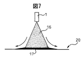
ここで、図7に噴霧ノズル1から粒状又は霧状にした潤滑油16を噴射対象である圧延ロール20の表面へ向かって噴射した状況を示す。
Here, FIG. 7 shows a state in which the
40℃における動粘度が60cSt以上の潤滑油を安定して粒状又は霧状にして噴霧ノズル1から噴射するには、ガスの圧力を0.05MPa以上に設定する必要がある。また、潤滑油が供給される圧延ロール20の表面上には常にロール冷却水が残存しているので、潤滑油16を効果的に圧延ロールに付着させるには、圧延ロール20の表面上の残存ロール冷却水を除去しなければならない。そのためには、噴霧ノズルから噴射されるガスは、少なくとも0.05MPa以上の圧力で噴射しなければならない。0.05MPa以上の圧力でガスを噴射すると、粒状又は霧状の潤滑油16を圧延ロール20の表面に供給すると同時に、残存ロール冷却水を吹き飛ばして、ロールに直接潤滑油を付着させる働きをするからである。さらに、0.05MPa以上の圧力で噴射供給されたガスは、付着した潤滑油17を均一にならす効果も奏する。
In order to stably inject a lubricating oil having a kinematic viscosity at 40 ° C. of 60 cSt or more into a granular or mist form and spray it from the
一方、ガスを1.0MPaよりも大きな圧力で潤滑油とともに噴射すると、たとえ40℃における動粘度が800cStの潤滑油でも、ロールに付着せずに周囲に飛散する量が多くなり、意図する潤滑油の量をロールに付着させることが困難となる。そればかりでなく、潤滑油を供給したい部分以外のところに潤滑油を付着させることになり、潤滑油の効率的な使用を阻害し不経済であるばかりでなく、良好な潤滑油使用環境維持の観点からも好ましいものではない。したがって、潤滑油を安定して圧延ロールに付着させるためには、ガスの圧力を1.0MPa以下に設定する必要がある。 On the other hand, when the gas is injected together with the lubricating oil at a pressure higher than 1.0 MPa, even if the lubricating oil has a kinematic viscosity of 800 cSt at 40 ° C., the amount of the oil splashing around without increasing on the roll increases. It becomes difficult to attach the amount of the material to the roll. Not only that, but it will cause the lubricant to adhere to areas other than the part where the lubricant is to be supplied, which not only impedes efficient use of the lubricant but is also uneconomical. It is not preferable also from a viewpoint. Therefore, in order to stably attach the lubricating oil to the rolling roll, it is necessary to set the gas pressure to 1.0 MPa or less.
また、内部混合型の2流体噴霧ノズルを使用する場合、噴霧ノズル内の混合チャンバーにおいて潤滑油とガスが共存する。このため、潤滑油を噴霧ノズルに供給するときの圧力が噴霧ノズル内の混合チャンバー内のガスの圧力よりも低いと、噴霧ノズル内の混合チャンバーに潤滑油を滞りなく安定して供給することが困難となり、場合によっては、潤滑油配管をガスが逆流してしまう。 In addition, when an internal mixing type two-fluid spray nozzle is used, lubricating oil and gas coexist in a mixing chamber in the spray nozzle. For this reason, if the pressure when supplying the lubricating oil to the spray nozzle is lower than the pressure of the gas in the mixing chamber in the spray nozzle, the lubricating oil can be stably and stably supplied to the mixing chamber in the spray nozzle. In some cases, the gas flows backward through the lubricating oil pipe.
したがって、内部混合型の2流体噴霧ノズルにおいて潤滑油を噴霧ノズル内の混合チャンバー内でガスと混合させてからロールに噴射するためには、潤滑油の噴霧ノズルへの供給時の圧力を、混合チャンバー内のガスの圧力以上に加圧しなければならない。なお、噴霧ノズル内の混合チャンバー内のガスの圧力とは、噴霧ノズルに潤滑油を送出せずにガスだけを噴霧ノズルに供給したときに、噴霧ノズルの潤滑油入口部付近の潤滑油配管内に作用する圧力である。混合チャンバー内のガスの圧力は噴射口の大きさなどの噴霧ノズルの構造と付加したガス源の元圧力(ガスの配管内の圧力)とに依存する。 Therefore, in order to inject the lubricating oil with the gas in the mixing chamber in the spray nozzle in the internal mixing type two-fluid spray nozzle and then inject it to the roll, the pressure at the time of supplying the lubricating oil to the spray nozzle is mixed. It must be pressurized above the pressure of the gas in the chamber. The pressure of the gas in the mixing chamber in the spray nozzle is defined as the pressure in the lubricating oil pipe near the lubricant inlet of the spray nozzle when only the gas is supplied to the spray nozzle without sending the lubricant to the spray nozzle. Is the pressure acting on The pressure of the gas in the mixing chamber depends on the structure of the spray nozzle such as the size of the injection port and the original pressure of the added gas source (pressure in the gas piping).
また、40℃における潤滑油の動粘度が60cSt以上800cSt以下の潤滑油を連続的に安定して噴霧ノズルに供給するには、潤滑設備の配管構成や長さ、内径などによって必要な圧力が変わるが、少なくとも0.01MPa以上の圧力をかける必要がある。さもなければ、配管詰まりなどが発生して、安定した供給が困難となる。潤滑油供給時の圧力は高ければ高いほど配管詰まりが発生しにくくなる。したがって、潤滑油を噴霧ノズルに圧送するときの潤滑油配管内の圧力は少なくとも0.01MPa以上であるのが好ましい。 Further, in order to continuously and stably supply a lubricating oil having a kinematic viscosity of 60 cSt or more and 800 cSt or less at 40 ° C. to the spray nozzle, the required pressure varies depending on the piping configuration, length, inner diameter, etc. of the lubrication equipment. However, it is necessary to apply a pressure of at least 0.01 MPa. Otherwise, piping clogging will occur, making stable supply difficult. The higher the pressure when supplying the lubricating oil, the less likely the piping will be clogged. Therefore, the pressure in the lubricating oil pipe when the lubricating oil is pumped to the spray nozzle is preferably at least 0.01 MPa.
一方で、極端な高圧で供給するには大容量のポンプ装置が必要になるほか、配管の耐圧能力も高くしなければならず、設備コストが高価になる。このため、潤滑油の供給時の圧力は3MPa以下に抑えることが好ましい。これらのことを考慮すると、潤滑油の供給時の圧力は0.05MPa以上3MPa以下にするのが好ましい。 On the other hand, in order to supply at an extremely high pressure, a large-capacity pump device is required, and the pressure resistance capacity of the piping must be increased, resulting in an increase in equipment cost. For this reason, it is preferable to suppress the pressure at the time of supply of lubricating oil to 3 MPa or less. Considering these matters, the pressure at the time of supplying the lubricating oil is preferably 0.05 MPa or more and 3 MPa or less.
一方、外部混合型の2流体噴霧ノズルは、内部混合型と異なり、噴霧ノズル内に潤滑油とガスを混合するためのチャンバーが無く、噴霧ノズルの噴射口のすぐ外側で潤滑油噴射流とガスの噴射流とを衝突させることで潤滑油を粒状又は霧状にして噴射対象物に噴射供給するものである。 On the other hand, unlike the internal mixing type, the external mixing type two-fluid spray nozzle has no chamber for mixing lubricating oil and gas in the spray nozzle, and the lubricating oil jet flow and gas are just outside the spray nozzle injection port. The lubricating oil is made into a granular shape or a mist shape by being collided with the jet flow, and is supplied to the injection target.
したがって、外部混合型の2流体噴霧ノズル内には、潤滑油の流路とガスの流路が独立して存在するので、潤滑油とガスの噴霧ノズルへの供給時の圧力などの条件が互いに影響を及ぼしあうことは殆ど無い。このため、上述したような動粘度の潤滑油が用いられる場合には、前記の通り、配管詰まりなどの防止や設備コスト抑制の観点から、ポンプ装置3を用いて少なくとも0.01MPa以上3MPaの圧力で噴霧ノズルに潤滑油を圧送すればよい。
Therefore, in the external mixing type two-fluid spray nozzle, since the lubricating oil flow path and the gas flow path exist independently, conditions such as pressure when supplying the lubricating oil and gas to the spray nozzle are mutually different. There is almost no influence. For this reason, when the lubricating oil having the kinematic viscosity as described above is used, as described above, the pressure of at least 0.01 MPa or more and 3 MPa using the
しかし、ガスの圧力よりも高い圧力で噴霧ノズルに潤滑油を供給し、そのまま潤滑油を噴霧ノズルから噴射すると、ガスの圧力が足りず、潤滑油が粒状もしくは霧状にならずに一部流体のような状態で噴霧ノズルから噴射される。この現象は、とりわけ40℃における潤滑油の動粘度範囲が60から800cStの潤滑油において発生しやすい。したがって、外部混合型の2流体噴霧ノズルを使用して噴射するときは、ガスの噴霧ノズルへの供給圧力よりも小さな圧力で潤滑油を圧送する。 However, if lubricating oil is supplied to the spray nozzle at a pressure higher than the gas pressure and the lubricating oil is sprayed from the spray nozzle as it is, the pressure of the gas is insufficient and the lubricating oil does not become granular or mist, but part fluid In such a state, it is injected from the spray nozzle. This phenomenon is particularly likely to occur in a lubricating oil having a kinematic viscosity range of 60 to 800 cSt at 40 ° C. Therefore, when jetting using an external mixing type two-fluid spray nozzle, the lubricating oil is pumped at a pressure smaller than the supply pressure of the gas to the spray nozzle.
なお、上記実施形態では、噴霧ノズル数と同数のポンプ装置3を設けて、各噴霧ノズルへの潤滑油供給量を制御することにしている。しかしながら、噴霧ノズル数よりもポンプ装置の数を少なくし、例えばポンプ装置の数を一つにすると共に、噴霧ノズル数と同数の流量調整弁を設けるようにしてもよい。この場合、各噴霧ノズルへの潤滑油供給量は各流量調整弁によって制御されることになる。
In the above embodiment, the same number of
また、上記実施形態では、内部混合型の2流体噴霧ノズルと外部混合型の2流体噴霧ノズルを併用している。しかしながら、必ずしも内部混合型の2流体噴霧ノズルと外部混合型の2流体噴霧ノズルを併用する必要はなく、一方のみを用いるようにしてもよい。いずれの2流体噴霧ノズルを使用するかは、潤滑油を供給する条件や部位に応じて、適宜選択される。 In the above embodiment, the internal mixing type two-fluid spray nozzle and the external mixing type two-fluid spray nozzle are used in combination. However, the internal mixing type two-fluid spray nozzle and the external mixing type two-fluid spray nozzle are not necessarily used in combination, and only one of them may be used. Which two-fluid spray nozzle is used is appropriately selected according to the condition and part for supplying the lubricating oil.
なお、これら2流体噴霧ノズルの使い分けに関しては、内部混合型2流体噴霧ノズルは、ノズル先端に混合室が設けられているので噴霧ノズルの噴射口の形状を変えることが容易であり、比較的フラットノズルとして使用されることが多い。フラットノズルは1個の噴霧ノズルで潤滑油の噴射幅が広くとれるので、薄板鋼帯用圧延ロールへの潤滑油供給には、このような噴霧ノズルが適していることが多い。これに対して、外部混合型2流体噴霧ノズルは、噴霧ノズルの噴射口の形状が円形のものが多いので、一様に噴霧することに適しており、ラウンドノズルとして使用されることが多い。 Regarding the proper use of these two-fluid spray nozzles, the internal mixing type two-fluid spray nozzle is provided with a mixing chamber at the tip of the nozzle, so that it is easy to change the shape of the spray nozzle and is relatively flat. Often used as a nozzle. Since the flat nozzle has a single spray nozzle and a wide spray width of the lubricating oil, such a spray nozzle is often suitable for supplying the lubricating oil to the sheet steel strip rolling roll. On the other hand, the external mixing type two-fluid spray nozzle is suitable for spraying uniformly because the shape of the spray nozzle has a circular shape, and is often used as a round nozzle.
次に、本発明の第二実施形態について説明する。ところで、潤滑油を供給するロール表面上に大量の水がかかっていたり、スケールなどが飛散している中で潤滑油を供給する必要があったりする場合、ガスを1.0MPa以上の圧力で噴射しなければならない場合が生じる。このようなときには噴射した潤滑油のうちロールに付着せず周囲に飛散する、いわゆる浮遊ミストの量が多くなり、非効率であるばかりでなく、潤滑油原単位の悪化を招く。 Next, a second embodiment of the present invention will be described. By the way, when a large amount of water is splashed on the surface of the roll for supplying the lubricating oil, or when it is necessary to supply the lubricating oil while the scale is scattered, the gas is injected at a pressure of 1.0 MPa or more. There is a case that must be done. In such a case, the amount of so-called floating mist that does not adhere to the roll and scatters around the sprayed lubricating oil increases, resulting in inefficiency and deterioration of the basic unit of lubricating oil.
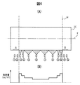
そこで、第二実施形態では、潤滑油を噴射しているときに形成される噴射コーンの周囲を水膜で覆うようにしている。図8(A)は、水膜形成装置を概略的に示す側面図であり、図8(B)は水膜形成装置を概略的に示す平面図である。図8(B)は、圧延ロール20の一方の端部近傍周りのみを示している。
Therefore, in the second embodiment, the periphery of the injection cone formed when the lubricating oil is injected is covered with a water film. FIG. 8A is a side view schematically showing the water film forming apparatus, and FIG. 8B is a plan view schematically showing the water film forming apparatus. FIG. 8B shows only the vicinity of one end of the rolling
図8(A)及び図8(B)からわかるように、水膜形成装置25は、水膜を形成させるように水を噴射する複数の水噴射ノズル26(26a、26b、26c)を具備する。水噴射ノズル26は、潤滑油の噴霧ノズルからの噴射コーンの上方に水膜を形成させるノズル26aと、潤滑油の噴霧ノズルからの噴射コーンの下方に水膜を形成させるノズル26bと、両端の潤滑油噴霧ノズルからの噴射コーンの側方(外側)に水膜を形成させるノズル26c(図8(B)には一方のみを記載)とを具備する。供給する水量は潤滑油の噴射条件によって変化するが、毎分1000cc以上の流量で水膜を形成することが好ましい。このように、潤滑油噴霧ノズルからの噴射コーンの周りに水膜を形成することによって、浮遊ミストの飛散量を格段に低減することができる。
As can be seen from FIGS. 8A and 8B, the water
なお、噴射コーンの周囲に水膜を形成させる手段としては、上述したような潤滑油を供給する2流体噴霧ノズル以外に水膜形成用のノズルを設置して水を供給する方法の他に、2流体噴霧ノズルの外側に水膜形成用の副ノズルを取り付け、ノズル噴射直後から潤滑油の噴射コーンの周囲に水膜を形成させる方法等が考えられる。潤滑油噴霧ノズルからの噴射コーンの周囲に水膜を形成することができれば如何なる方法を用いてもよい。 As a means for forming a water film around the spray cone, in addition to the method of supplying water by installing a nozzle for forming a water film in addition to the two-fluid spray nozzle that supplies lubricating oil as described above, A method may be considered in which a sub-nozzle for forming a water film is attached to the outside of the two-fluid spray nozzle, and a water film is formed around the injection cone of the lubricating oil immediately after nozzle injection. Any method may be used as long as a water film can be formed around the spray cone from the lubricant spray nozzle.
第一スタンドから第七スタンドまでの7台の圧延機で構成される熱間仕上圧延機の第五スタンドにおいて潤滑油供給量の制御を行った。被圧延鋼材は第一スタンドから順に第七スタンドまで通され各スタンドにおいて圧延が行われる。被圧延鋼材には一般的な低炭素鋼を用い、第一スタンド入側板厚が32mmであったものを第七スタンド出側板厚が2.3mmとなるように圧延を行った。被圧延鋼材としては板幅が1820mmから1940mmのものを用いた。 Lubricating oil supply amount was controlled in the fifth stand of the hot finish rolling mill composed of seven rolling mills from the first stand to the seventh stand. The steel material to be rolled is passed from the first stand to the seventh stand in order, and rolled in each stand. A general low carbon steel was used as the steel to be rolled, and the first stand entry side plate thickness was 32 mm and rolled so that the seventh stand exit side plate thickness was 2.3 mm. As the steel material to be rolled, one having a plate width of 1820 mm to 1940 mm was used.
噴霧ノズルを圧延ロールの軸方向に並べたヘッダーを設置し、潤滑油供給量を個別に設定できるギヤポンプを各噴霧ノズルに接続した。ヘッダーに対しては、図5に示したように噴霧ノズルの配置を行った。圧延ロールはロール研磨後にロールプロフィールを測定したものを用いた。潤滑油には40℃における動粘度が230cStであるものを使用した。噴射供給用のガスにはエアーを用いた。潤滑油の供給は、非圧延材が圧延機に咬み込まれたと同時に開始し、第五スタンドを鋼材が抜けたのと同時に供給を終了した。 A header with spray nozzles arranged in the axial direction of the rolling roll was installed, and a gear pump capable of individually setting the amount of lubricating oil was connected to each spray nozzle. For the header, spray nozzles were arranged as shown in FIG. The rolling roll used was a roll profile measured after roll polishing. A lubricating oil having a kinematic viscosity at 40 ° C. of 230 cSt was used. Air was used as the gas for jet supply. The supply of the lubricating oil started as soon as the non-rolled material was bitten by the rolling mill, and the supply was finished as soon as the steel material was removed from the fifth stand.
はじめに下記表1の条件に示す潤滑油供給条件で潤滑圧延を実施し、約245トン圧延を実施した。その後、ロールを引き出し、ロールプロフィールを測定して、各噴霧ノズルの潤滑油供給領域毎の平均摩耗深さとロール全体の平均摩耗深さを算出した。ロール全体に対する、各噴霧ノズルの潤滑油供給領域における平均ロール摩耗深さの比率を算出し、その比率に係数α(本実施例では、1.0)と、各噴霧ノズルの初期の潤滑油供給量(表1の条件)に乗じた値を、次回の圧延時の潤滑油供給量とした。その後、ロールを組み込み、所定圧延量までの潤滑圧延を継続して実施した。

このようにして、ロールプロフィール測定と潤滑油供給量の修正とを繰り返したときの、ロール幅方向の最大平均摩耗深さと最小平均摩耗深さとの差異を測定した結果を表2に示す。こうした潤滑圧延を繰り返すことによってロールプロフィールの摩耗偏差を少なくすることができ、初期のロールプロフィールに近い状態で圧延することが可能になる。なお、表2中の「比率」は、中央噴霧ノズルからの潤滑油供給量に対する側方噴霧ノズルからの潤滑油供給量の比率を表している。
1 :潤滑油供給用ノズル(ここでは、2流体気液混合噴霧型、ガスアトマイズ法用)
1a :内部混合型の2流体噴霧ノズル
1b :外部混合型の2流体噴霧ノズル
1´:潤滑供給用ノズル(1流体型、ウォーターインジェクション法用)
2 :潤滑油スイッチ
3 :ポンプ装置(潤滑油送出用)
3´:ポンプ装置(水送出用)
4 :潤滑油貯蔵タンク
5 :不燃性ガス源
6 :ガススイッチ
8 :インジェクター(水と潤滑油の混合器)
9 :水源
10 :水の供給をON/OFFするための装置
11 :ガス
12 :圧送される潤滑油
16 :粒状もしくは霧状になった潤滑油
17 :噴射対象に付着した潤滑油
18 :混合室
20 :圧延ロール
M :金属材料(被圧延材)
X :軸線1: Lubricating oil supply nozzle (here, two-fluid gas-liquid mixed spray type, gas atomization method)
1a: Internally mixed two-
2: Lubricating oil switch 3: Pump device (for sending lubricating oil)
3 ': Pump device (for water delivery)
4: Lubricating oil storage tank 5: Nonflammable gas source 6: Gas switch 8: Injector (mixer of water and lubricating oil)
9: Water source 10: Device for turning ON / OFF the supply of water 11: Gas 12: Lubricating
X: Axis
Claims (16)
前記圧延ロールの軸方向に配置され、潤滑油を前記圧延ロールに向けてガスと共に粒状化又は霧状化して噴射する複数の噴霧ノズルと、
各噴霧ノズルに潤滑油を供給する潤滑油供給装置と、
各噴霧ノズルにガスを供給するガス供給装置とを具備し、
前記板状金属材料の板幅に対応する前記圧延ロールの部分への潤滑油の供給を行う噴霧ノズルのうち両端に位置する噴霧ノズルを側方噴霧ノズル、中央に位置する噴霧ノズルを中央噴霧ノズルとすると、側方噴霧ノズルからの潤滑油供給量は中央噴霧ノズルからの潤滑油供給量よりも多く、これら側方噴霧ノズルと中央噴霧ノズルとの間の噴霧ノズルからの潤滑油供給量は前記側方噴霧ノズルからの潤滑油供給量以下であって前記中央噴霧ノズルからの潤滑油供給量以上である、圧延機用の潤滑油供給設備。Lubricating oil supply equipment for a rolling roll of a sheet metal rolling mill,
A plurality of spray nozzles that are arranged in the axial direction of the rolling roll and spray the lubricating oil into the rolling roll in a granulated or atomized form together with a gas;
A lubricating oil supply device for supplying lubricating oil to each spray nozzle;
A gas supply device for supplying gas to each spray nozzle,
Of the spray nozzles for supplying lubricating oil to the portion of the rolling roll corresponding to the plate width of the plate metal material, the spray nozzles located at both ends are the side spray nozzles, and the spray nozzle located at the center is the central spray nozzle Then, the lubricating oil supply amount from the side spray nozzle is larger than the lubricating oil supply amount from the central spray nozzle, and the lubricating oil supply amount from the spray nozzle between these side spray nozzles and the central spray nozzle is Lubricating oil supply equipment for a rolling mill that is equal to or less than the lubricating oil supply amount from the side spray nozzle and equal to or greater than the lubricating oil supply amount from the central spray nozzle.
前記潤滑油供給装置は、前記内部混合型の噴霧ノズルに、該噴霧ノズルの混合チャンバー内におけるガスの圧力以上の圧力で潤滑油を供給する、請求項1に記載の圧延機用の潤滑油供給設備。At least a part of the spray nozzle is an internal mixing type spray nozzle, the lubricating oil has a kinematic viscosity at 40 ° C. of 60 to 800 cSt, and the gas supply device gasses the spray nozzle at a pressure of 0.05 MPa or more. Supply
2. The lubricating oil supply for a rolling mill according to claim 1, wherein the lubricating oil supply device supplies the internal mixing type spray nozzle to a lubricating oil at a pressure equal to or higher than a gas pressure in a mixing chamber of the spray nozzle. Facility.
前記潤滑油供給装置は、前記外部混合型の噴霧ノズルに0.01MPa以上であって前記噴霧ノズルへのガスの供給圧力よりも低い圧力で潤滑油を供給する、請求項1に記載の圧延機用の潤滑油供給装置。At least a part of the spray nozzle is an externally mixed spray nozzle, the lubricating oil has a kinematic viscosity at 40 ° C. of 60 to 800 cSt, and the gas supply device gasses the spray nozzle at a pressure of 0.05 MPa or more. Supply
The rolling mill according to claim 1, wherein the lubricating oil supply device supplies the lubricating oil to the external mixing type spray nozzle at a pressure of 0.01 MPa or more and lower than a gas supply pressure to the spray nozzle. Lubricating oil supply device.
前記板状金属材料の板幅方向において、中央に内部混合型の噴霧ノズルが配置され、外側に外部混合型の噴霧ノズルが配置される、請求項7に記載の圧延機用の潤滑油供給装置。The spray nozzle comprises an internal mixing type spray nozzle and an external mixing type spray nozzle,
The lubricating oil supply device for a rolling mill according to claim 7, wherein an internal mixing type spray nozzle is disposed in the center and an external mixing type spray nozzle is disposed outside in the plate width direction of the plate-like metal material. .
複数の噴霧ノズルから前記圧延ロールに向けて潤滑油をガスと共に粒状化又は霧状化して噴射すると共に、
前記板状金属材料の板幅に対応する前記圧延ロールの部分への潤滑油の供給を行う噴霧ノズルのうち両端に位置する噴霧ノズルを側方噴霧ノズル、中央に位置する噴霧ノズルを中央噴霧ノズルとすると、前記噴霧ノズルからの噴射の際には、側方噴霧ノズルからの潤滑油供給量を中央噴霧ノズルからの潤滑油供給量よりも多くし、これら側方噴霧ノズルと中央噴霧ノズルとの間の噴霧ノズルからの潤滑油供給量を前記側方噴霧ノズルからの潤滑油供給量以下であって前記中央噴霧ノズルからの潤滑油供給量以上とする、圧延ロールへの潤滑油供給方法。In the method of supplying lubricating oil on the surface of the rolling roll,
Lubricating oil is granulated or atomized together with gas and sprayed from a plurality of spray nozzles toward the rolling roll,
Of the spray nozzles for supplying lubricating oil to the portion of the rolling roll corresponding to the plate width of the plate metal material, the spray nozzles located at both ends are the side spray nozzles, and the spray nozzle located at the center is the central spray nozzle Then, when spraying from the spray nozzle, the amount of lubricating oil supplied from the side spray nozzle is made larger than the amount of lubricating oil supplied from the central spray nozzle, and the side spray nozzle and the central spray nozzle A method for supplying lubricating oil to a rolling roll, wherein the amount of lubricating oil supplied from the spray nozzle in the meantime is not more than the amount of lubricating oil supplied from the side spray nozzle and not less than the amount of lubricating oil supplied from the central spray nozzle.
前記内部混合型の噴霧ノズルには、0.05MPa以上の圧力でガスを供給すると共に、該噴霧ノズルの混合チャンバー内におけるガスの圧力以上の圧力で潤滑油を供給する、請求項10に記載の圧延ロールへの潤滑油供給方法。At least a part of the spray nozzle is an internal mixing type spray nozzle, and the lubricating oil has a kinematic viscosity at 40 ° C. of 60 to 800 cSt,
11. The internal mixing type spray nozzle is supplied with gas at a pressure of 0.05 MPa or more, and is supplied with lubricating oil at a pressure higher than the pressure of the gas in the mixing chamber of the spray nozzle. Lubricating oil supply method to rolling rolls.
前記外部混合型の噴霧ノズルには、0.05MPa以上の圧力でガスを供給すると共に、0.01MPa以上であって前記噴霧ノズルへのガスの供給圧力よりも低い圧力で潤滑油を供給する、請求項10に記載の圧延ロールへの潤滑油供給方法。At least a part of the spray nozzle is an external mixing type spray nozzle, and the lubricating oil has a kinematic viscosity at 40 ° C. of 60 to 800 cSt,
The external mixing type spray nozzle is supplied with gas at a pressure of 0.05 MPa or more, and is supplied with lubricating oil at a pressure of 0.01 MPa or more and lower than the gas supply pressure to the spray nozzle. The lubricating oil supply method to the rolling roll of Claim 10.
Priority Applications (1)
| Application Number | Priority Date | Filing Date | Title |
|---|---|---|---|
| JP2012506263A JP4980504B2 (en) | 2010-04-07 | 2011-04-06 | Lubricating oil supply facility and lubricating oil supplying method |
Applications Claiming Priority (4)
| Application Number | Priority Date | Filing Date | Title |
|---|---|---|---|
| JP2010088371 | 2010-04-07 | ||
| JP2010088371 | 2010-04-07 | ||
| JP2012506263A JP4980504B2 (en) | 2010-04-07 | 2011-04-06 | Lubricating oil supply facility and lubricating oil supplying method |
| PCT/JP2011/059124 WO2011126139A1 (en) | 2010-04-07 | 2011-04-06 | Lubricating oil supply facility and lubricating oil supply method |
Publications (2)
| Publication Number | Publication Date |
|---|---|
| JP4980504B2 true JP4980504B2 (en) | 2012-07-18 |
| JPWO2011126139A1 JPWO2011126139A1 (en) | 2013-07-11 |
Family
ID=44763073
Family Applications (1)
| Application Number | Title | Priority Date | Filing Date |
|---|---|---|---|
| JP2012506263A Active JP4980504B2 (en) | 2010-04-07 | 2011-04-06 | Lubricating oil supply facility and lubricating oil supplying method |
Country Status (8)
| Country | Link |
|---|---|
| US (1) | US8713981B2 (en) |
| EP (2) | EP2556902B1 (en) |
| JP (1) | JP4980504B2 (en) |
| KR (1) | KR101299298B1 (en) |
| CN (1) | CN102844127B (en) |
| BR (2) | BR112012025589B1 (en) |
| TW (1) | TWI420038B (en) |
| WO (1) | WO2011126139A1 (en) |
Families Citing this family (14)
| Publication number | Priority date | Publication date | Assignee | Title |
|---|---|---|---|---|
| DE102008050392A1 (en) * | 2008-06-18 | 2009-12-24 | Sms Siemag Aktiengesellschaft | Method and device for lubricating rolls and a rolled strip of a roll stand |
| EP2893986A1 (en) * | 2014-01-08 | 2015-07-15 | Siemens VAI Metals Technologies GmbH | Lubrication with spray nozzles with multiple oil inlet openings |
| DE202015009746U1 (en) * | 2014-05-09 | 2019-10-31 | Novelis Inc. | Hybrid oil and water cooled rolling |
| GB201410562D0 (en) | 2014-06-13 | 2014-07-30 | Nicoventures Holdings Ltd | Aerosol provision system |
| US20170033184A1 (en) * | 2015-07-27 | 2017-02-02 | International Business Machines Corporation | Semiconductor device including fin having condensed channel region |
| EP3352922B1 (en) | 2015-09-21 | 2020-09-02 | Novelis Inc. | Pre-heating and thermal control of work rolls in metal rolling processes and control system thereof |
| US20170186747A1 (en) * | 2015-12-29 | 2017-06-29 | International Business Machines Corporation | STRUCTURE AND METHOD FOR SiGe FIN FORMATION IN A SEMICONDUCTOR DEVICE |
| CN105752107A (en) * | 2016-03-03 | 2016-07-13 | 武汉理工大学 | Noise reduction device for monitoring and automatically controlling application of friction improver based on rail vibration |
| JP6651986B2 (en) * | 2016-05-27 | 2020-02-19 | 日本製鉄株式会社 | Lubricating oil supply method in hot rolling |
| KR102109262B1 (en) * | 2018-08-16 | 2020-05-11 | 주식회사 포스코 | Lubricating apparatus |
| CN109174486A (en) * | 2018-10-09 | 2019-01-11 | 广州汇专工具有限公司 | A kind of low temperature process nozzle |
| CN109821902B (en) * | 2019-01-30 | 2020-09-25 | 北京首钢股份有限公司 | Method for improving transverse lubricating capability distribution of edge profile of silicon steel |
| KR102239179B1 (en) * | 2019-10-15 | 2021-04-12 | 주식회사 포스코 | Apparatus supplying mixed solution in rolling equipment |
| CN114101324B (en) * | 2021-10-29 | 2023-08-25 | 马鞍山钢铁股份有限公司 | Inorganic self-lubricating galvanized steel strip for automobile and production method thereof |
Citations (2)
| Publication number | Priority date | Publication date | Assignee | Title |
|---|---|---|---|---|
| JPH09253707A (en) * | 1996-03-19 | 1997-09-30 | Sumitomo Metal Ind Ltd | Skin-pass rolling method |
| JP2009226478A (en) * | 2008-02-26 | 2009-10-08 | Nippon Steel Corp | Lubricant supplying equipment, rolling mill and method of supplying lubricant, rolling method |
Family Cites Families (17)
| Publication number | Priority date | Publication date | Assignee | Title |
|---|---|---|---|---|
| US4738400A (en) * | 1987-02-11 | 1988-04-19 | Almo Manifold & Tool Co. | Spray bar assembly |
| JPH03138014A (en) * | 1989-10-25 | 1991-06-12 | Kawasaki Steel Corp | Profile control method of hot rolled steel plate |
| JPH07290121A (en) | 1994-04-22 | 1995-11-07 | Nippon Steel Corp | Universal rolling method for shape steel with flange |
| JP3694427B2 (en) | 1998-10-28 | 2005-09-14 | 新日本製鐵株式会社 | Pore rolling method by solid lubrication |
| US6134930A (en) | 2000-01-26 | 2000-10-24 | Morgan Construction Company | Lubrication system |
| JP2002316202A (en) | 2001-04-18 | 2002-10-29 | Nakayama Steel Works Ltd | Lubricating device for rolling plate, and lubricant jetting nozzle |
| JP4203236B2 (en) | 2001-09-21 | 2008-12-24 | 新日本製鐵株式会社 | Lubrication supply method in hot rolling |
| JP4123865B2 (en) * | 2002-08-12 | 2008-07-23 | 株式会社Ihi | Pinch roll lubrication mist sprayer |
| CN2628172Y (en) * | 2003-03-27 | 2004-07-28 | 宝山钢铁股份有限公司 | Roll edge lubricating apparatus |
| JP4355280B2 (en) | 2004-11-22 | 2009-10-28 | 新日本製鐵株式会社 | Lubricating oil supply method in cold rolling |
| JP4355279B2 (en) | 2004-11-22 | 2009-10-28 | 新日本製鐵株式会社 | Lubricating oil supply method in cold rolling |
| KR100668698B1 (en) | 2005-11-08 | 2007-01-16 | 주식회사 포스코 | Apparatus and method supplying lubricant in endless hot rolling equipment |
| CN1911545B (en) * | 2006-08-18 | 2012-05-23 | 上海诸光机械有限公司 | Technological lubricating system of hot mill steel plate continuous milling machine |
| JP4962055B2 (en) | 2007-03-07 | 2012-06-27 | Jfeスチール株式会社 | Cold rolling method and cold rolling apparatus |
| BE1017806A3 (en) * | 2007-10-08 | 2009-07-07 | Ct Rech Metallurgiques Asbl | ATOMIZATION LUBRICATION SYSTEM AND METHOD FOR ROLLING CYLINDERS. |
| DE102008050392A1 (en) | 2008-06-18 | 2009-12-24 | Sms Siemag Aktiengesellschaft | Method and device for lubricating rolls and a rolled strip of a roll stand |
| JP4954961B2 (en) | 2008-10-06 | 2012-06-20 | 大日本住友製薬株式会社 | Composition with improved photostability |
-
2011
- 2011-04-06 EP EP11766038.1A patent/EP2556902B1/en active Active
- 2011-04-06 KR KR1020127025713A patent/KR101299298B1/en active IP Right Grant
- 2011-04-06 US US13/639,198 patent/US8713981B2/en active Active
- 2011-04-06 WO PCT/JP2011/059124 patent/WO2011126139A1/en active Application Filing
- 2011-04-06 BR BR112012025589-4A patent/BR112012025589B1/en active IP Right Grant
- 2011-04-06 EP EP15198727.8A patent/EP3028781B1/en active Active
- 2011-04-06 CN CN201180017515.7A patent/CN102844127B/en active Active
- 2011-04-06 BR BR122020002003-2A patent/BR122020002003B1/en active IP Right Grant
- 2011-04-06 JP JP2012506263A patent/JP4980504B2/en active Active
- 2011-04-07 TW TW100112023A patent/TWI420038B/en not_active IP Right Cessation
Patent Citations (2)
| Publication number | Priority date | Publication date | Assignee | Title |
|---|---|---|---|---|
| JPH09253707A (en) * | 1996-03-19 | 1997-09-30 | Sumitomo Metal Ind Ltd | Skin-pass rolling method |
| JP2009226478A (en) * | 2008-02-26 | 2009-10-08 | Nippon Steel Corp | Lubricant supplying equipment, rolling mill and method of supplying lubricant, rolling method |
Also Published As
| Publication number | Publication date |
|---|---|
| BR112012025589B1 (en) | 2021-05-25 |
| WO2011126139A1 (en) | 2011-10-13 |
| US8713981B2 (en) | 2014-05-06 |
| KR20120123595A (en) | 2012-11-08 |
| EP3028781B1 (en) | 2018-06-13 |
| EP2556902B1 (en) | 2015-12-16 |
| CN102844127B (en) | 2015-04-01 |
| EP3028781A1 (en) | 2016-06-08 |
| EP2556902A1 (en) | 2013-02-13 |
| BR112012025589A2 (en) | 2016-06-21 |
| US20130019647A1 (en) | 2013-01-24 |
| BR122020002003B1 (en) | 2021-07-06 |
| CN102844127A (en) | 2012-12-26 |
| EP2556902A4 (en) | 2014-02-26 |
| TW201200776A (en) | 2012-01-01 |
| KR101299298B1 (en) | 2013-08-26 |
| TWI420038B (en) | 2013-12-21 |
| JPWO2011126139A1 (en) | 2013-07-11 |
Similar Documents
| Publication | Publication Date | Title |
|---|---|---|
| JP4980504B2 (en) | Lubricating oil supply facility and lubricating oil supplying method | |
| US9254513B2 (en) | Method and device for lubricating rollers and a rolled strip of a rolling stand | |
| US9433986B2 (en) | Rolling mill roll-cleaning device and cleaning method | |
| JP2011524257A5 (en) | ||
| JP4505231B2 (en) | Lubricating oil supply method in cold rolling | |
| JP6350274B2 (en) | Lubricating oil supply equipment for cold rolling mills | |
| JP5633463B2 (en) | Lubricating oil supply device for cold rolling mill | |
| JP5577925B2 (en) | Lubrication supply method and lubrication supply apparatus in cold rolling | |
| JP2006263741A (en) | Method of supplying lubricating oil in cold rolling | |
| JP6201430B2 (en) | Lubricating oil supply method and lubrication rolling method for cold rolling mill | |
| JP2006142339A (en) | Method for supplying lubricant in hot rolling | |
| JP5577880B2 (en) | Lubricating oil supply method | |
| JP2010023076A (en) | Cold-rolling method and cold-rolling equipment excellent in heat scratch resistance and method of manufacturing cold-rolled metal sheet excellent in heat-scratch resistance | |
| JP2009050884A (en) | Method and device for lubricating roll of hot rolling mill |
Legal Events
| Date | Code | Title | Description |
|---|---|---|---|
| TRDD | Decision of grant or rejection written | ||
| A01 | Written decision to grant a patent or to grant a registration (utility model) |
Free format text: JAPANESE INTERMEDIATE CODE: A01 Effective date: 20120327 |
|
| A01 | Written decision to grant a patent or to grant a registration (utility model) |
Free format text: JAPANESE INTERMEDIATE CODE: A01 |
|
| A61 | First payment of annual fees (during grant procedure) |
Free format text: JAPANESE INTERMEDIATE CODE: A61 Effective date: 20120418 |
|
| FPAY | Renewal fee payment (event date is renewal date of database) |
Free format text: PAYMENT UNTIL: 20150427 Year of fee payment: 3 |
|
| R151 | Written notification of patent or utility model registration |
Ref document number: 4980504 Country of ref document: JP Free format text: JAPANESE INTERMEDIATE CODE: R151 |
|
| FPAY | Renewal fee payment (event date is renewal date of database) |
Free format text: PAYMENT UNTIL: 20150427 Year of fee payment: 3 |
|
| S533 | Written request for registration of change of name |
Free format text: JAPANESE INTERMEDIATE CODE: R313533 |
|
| FPAY | Renewal fee payment (event date is renewal date of database) |
Free format text: PAYMENT UNTIL: 20150427 Year of fee payment: 3 |
|
| R350 | Written notification of registration of transfer |
Free format text: JAPANESE INTERMEDIATE CODE: R350 |
|
| S533 | Written request for registration of change of name |
Free format text: JAPANESE INTERMEDIATE CODE: R313533 |
|
| R350 | Written notification of registration of transfer |
Free format text: JAPANESE INTERMEDIATE CODE: R350 |