JP4977147B2 - Drive connection of bell-band for disc brake - Google Patents
Drive connection of bell-band for disc brake Download PDFInfo
- Publication number
- JP4977147B2 JP4977147B2 JP2008548085A JP2008548085A JP4977147B2 JP 4977147 B2 JP4977147 B2 JP 4977147B2 JP 2008548085 A JP2008548085 A JP 2008548085A JP 2008548085 A JP2008548085 A JP 2008548085A JP 4977147 B2 JP4977147 B2 JP 4977147B2
- Authority
- JP
- Japan
- Prior art keywords
- connecting means
- brake
- band
- plate
- bell
- Prior art date
- Legal status (The legal status is an assumption and is not a legal conclusion. Google has not performed a legal analysis and makes no representation as to the accuracy of the status listed.)
- Active
Links
- 230000008878 coupling Effects 0.000 claims abstract 6
- 238000010168 coupling process Methods 0.000 claims abstract 6
- 238000005859 coupling reaction Methods 0.000 claims abstract 6
- 238000000034 method Methods 0.000 claims description 12
- 230000005540 biological transmission Effects 0.000 description 2
- 238000009434 installation Methods 0.000 description 2
- 238000004519 manufacturing process Methods 0.000 description 2
- 238000005266 casting Methods 0.000 description 1
- 238000006467 substitution reaction Methods 0.000 description 1
Images


Classifications
-
- F—MECHANICAL ENGINEERING; LIGHTING; HEATING; WEAPONS; BLASTING
- F16—ENGINEERING ELEMENTS AND UNITS; GENERAL MEASURES FOR PRODUCING AND MAINTAINING EFFECTIVE FUNCTIONING OF MACHINES OR INSTALLATIONS; THERMAL INSULATION IN GENERAL
- F16D—COUPLINGS FOR TRANSMITTING ROTATION; CLUTCHES; BRAKES
- F16D65/00—Parts or details
- F16D65/02—Braking members; Mounting thereof
- F16D65/12—Discs; Drums for disc brakes
-
- F—MECHANICAL ENGINEERING; LIGHTING; HEATING; WEAPONS; BLASTING
- F16—ENGINEERING ELEMENTS AND UNITS; GENERAL MEASURES FOR PRODUCING AND MAINTAINING EFFECTIVE FUNCTIONING OF MACHINES OR INSTALLATIONS; THERMAL INSULATION IN GENERAL
- F16D—COUPLINGS FOR TRANSMITTING ROTATION; CLUTCHES; BRAKES
- F16D65/00—Parts or details
- F16D65/02—Braking members; Mounting thereof
- F16D2065/13—Parts or details of discs or drums
- F16D2065/1304—Structure
- F16D2065/1316—Structure radially segmented
-
- F—MECHANICAL ENGINEERING; LIGHTING; HEATING; WEAPONS; BLASTING
- F16—ENGINEERING ELEMENTS AND UNITS; GENERAL MEASURES FOR PRODUCING AND MAINTAINING EFFECTIVE FUNCTIONING OF MACHINES OR INSTALLATIONS; THERMAL INSULATION IN GENERAL
- F16D—COUPLINGS FOR TRANSMITTING ROTATION; CLUTCHES; BRAKES
- F16D65/00—Parts or details
- F16D65/02—Braking members; Mounting thereof
- F16D2065/13—Parts or details of discs or drums
- F16D2065/134—Connection
- F16D2065/1356—Connection interlocking
- F16D2065/136—Connection interlocking with relative movement radially
-
- F—MECHANICAL ENGINEERING; LIGHTING; HEATING; WEAPONS; BLASTING
- F16—ENGINEERING ELEMENTS AND UNITS; GENERAL MEASURES FOR PRODUCING AND MAINTAINING EFFECTIVE FUNCTIONING OF MACHINES OR INSTALLATIONS; THERMAL INSULATION IN GENERAL
- F16D—COUPLINGS FOR TRANSMITTING ROTATION; CLUTCHES; BRAKES
- F16D65/00—Parts or details
- F16D65/02—Braking members; Mounting thereof
- F16D2065/13—Parts or details of discs or drums
- F16D2065/134—Connection
- F16D2065/1392—Connection elements
Landscapes
- Engineering & Computer Science (AREA)
- General Engineering & Computer Science (AREA)
- Mechanical Engineering (AREA)
- Braking Arrangements (AREA)
Abstract
Description
本発明の対象は、サポートベルとブレーキバンドとの間における駆動連結を改良したブレーキディスクである。 The subject of the invention is a brake disc with improved drive connection between the support bell and the brake band.
ディスクブレーキの分野において、ブレーキディスクを2つの別個体、すなわちサポートベルとブレーキバンドとして製造することは、公知であり十分に理解されている。 In the field of disc brakes, it is known and well understood to manufacture brake discs as two separate bodies: a support bell and a brake band.
この技術的解決方法によって、重要な利点が生じる。まず、ブレーキ動作中に高い温度に達することがあるブレーキバンドがサポートベルによって生じるいかなる制限をも受けることなく膨張することが可能となる。さらに、この解決方法によって、これら2つの部分を互いに異なる素材を用いて製造することが可能となるため、ブレーキディスクの全体的性能を最適化することが可能となる。 This technical solution provides important advantages. First, it is possible for a brake band that can reach high temperatures during braking to expand without any limitations imposed by the support bell. Furthermore, this solution makes it possible to produce these two parts using different materials, so that the overall performance of the brake disc can be optimized.
また、バンドとベルとの間における構造的連結のために選択された解決方法も、幾つかの利点を得るのに決定的に寄与するものである。 The solution chosen for the structural connection between the band and the bell also contributes decisively in obtaining several advantages.
例えば、バンド用とベル用に異なる素材を使用した場合であっても、ブレーキディスク全体を1つの製造工程によって得ることが可能であることが知られている。この結果は、例えば共鋳造工程によって達成することが可能である。 For example, it is known that the entire brake disc can be obtained by a single manufacturing process even when different materials are used for the band and the bell. This result can be achieved, for example, by a co-casting process.
また、ブレーキバンドとサポートベルとを互いに独立して設け、その後に組み立てて初めてブレーキディスクを構成するようにすることも知られている。 It is also known that a brake disk and a support bell are provided independently of each other, and a brake disk is configured only after assembly.
この解決方法は、いわゆる駆動連結、すなわちベルとバンドとを構造的に連結するのに適合しブレーキトルクの伝達と所望のバックラッシュあるいはギャップを保証する、別の手段の使用を伴うものである。 This solution involves the use of a so-called drive connection, i.e. another means adapted to structurally connect the bell and the band to ensure the transmission of brake torque and the desired backlash or gap.
例えば高性能の競技用オートバイの分野など、特定の分野においては、前述の全ての利点を保証した上で、大幅に容易な取り付けを保証する駆動連結は、特に高く評価されるものである。 In certain fields, for example in the field of high-performance racing motorcycles, a drive connection that guarantees a much easier installation while guaranteeing all the advantages mentioned above is particularly appreciated.
更に、このような駆動連結は、例えばブレーキバンドが磨耗した際に、サポートベルも同時に取り替える必要がないままで、ブレーキバンドのみを素早く交換することができるようにするものである。 Furthermore, such a drive connection allows for quick replacement of the brake band only, for example when the brake band is worn, without having to replace the support bell at the same time.
ベルの軸方向における突起とバンドの内側の半径方向の突起とが連結することを可能とする軸方向運動によってバンドとベルとが組み立てられているブレーキディスクが、特許文献1により公知である。組み立ては、例えばリベット打ちによってその位置を固定することができる弾性を有する固定具を適用することによって終了する。この解決方法は、必要とする部品数が少なくて済むものの、ブレーキディスクの容易な組み立てを可能にするものではなく、何よりもその組み立て後に分解することを許容するものでない。 A brake disc in which the band and the bell are assembled by axial movement that allows the projection in the axial direction of the bell and the radial projection inside the band to be connected is known from US Pat. The assembly is completed by applying an elastic fixture that can fix its position, for example by riveting. Although this solution requires fewer parts, it does not allow for easy assembly of the brake disc, and above all does not allow it to be disassembled after its assembly.
また、特許文献2により、複数のプレートを使用する駆動連結であって、各プレートがバンドの内側の半径方向の突起をベルの外径方向における突起に対して連結するものが公知である。前記プレートのそれぞれが、2つのナットによるネジ結合によって締結固定される。この技術的特徴においては、組み立てが必要な多くの数の部品と、これに伴って非常に複雑なブレーキディスクの取り付けおよび取り外し操作とが必要となる。
本発明の目的は、先行技術に関して引き合いに出された欠点を克服することが可能な、サポートベルとブレーキバンドとの間の駆動連結を有するブレーキディスクを、案出し提供することにある。 It is an object of the present invention to devise and provide a brake disc having a drive connection between a support bell and a brake band, which is capable of overcoming the drawbacks cited with respect to the prior art.
具体的に、本発明の課題は、速い組み立て速度を可能とする駆動連結を提供することにある。 Specifically, it is an object of the present invention to provide a drive connection that allows a fast assembly speed.
本発明の別の課題は、ベルとバンドとの間における連結に使用される機械部品の数を低減することが可能な駆動連結を提供することにある。 Another object of the present invention is to provide a drive connection that can reduce the number of mechanical parts used for the connection between the bell and the band.
この目的とこれらの課題は、請求項1によるブレーキディスクと請求項21による使用方法とによって達成することが可能である。
This object and these objects can be achieved by a brake disc according to claim 1 and a method of use according to
本発明によるブレーキディスクの更なる特徴および利点は、以下において記載される好ましい実施形態の説明から理解され得るものであるが、これら実施形態は、以下における添付図面を参照しつつ、例示的であって限定的でない一例として述べられているものである。 Further features and advantages of the brake disc according to the invention can be understood from the description of the preferred embodiments described below, which are exemplary only with reference to the accompanying drawings in the following. It is described as a non-limiting example.
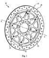
図面を参照するに、ブレーキディスクは、その全体が符号10で示されている。ブレーキディスク10は、符号20で示されるサポートベル(あるいは単に「ベル」)と、符号30で示されるブレーキバンド(あるいは単に「バンド」)とを備えている。
Referring to the drawings, the brake disk is generally designated 10. The
ブレーキディスク10は、一義的にX軸を画定するものである。このX軸に対して平行であるすべての直線の方向が、本文において「軸方向である」と定義される。X軸を起点とし、これに対して垂直である半直線の方向は、本文において「半径方向である」と定義される。最後に、X軸に中心があり、これに対して垂直である平面上にある円周に対して接する全ての直線の方向は、本文において「接線方向である」と定義される。
The
ブレーキバンド30は、第1の接続手段31を備えている。好ましい実施形態においては、ブレーキバンド30は、複数の第1の接続手段31を備えている。
The
サポートベル20は、第1の接続手段31に対面するように構成された第2の接続手段21を備えている。好ましい実施形態においては、サポートベル20は、バンド30の複数の第1の接続手段31にそれぞれ対面するように構成された複数の第2の接続手段を備えている。
The
ブレーキディスク10は、それぞれが前記第1の接続手段31あるいは前記第2の接続手段21のうちの何れかとスライド式に連係するように構成された連結手段41を、更に備えている。或る実施形態においては、ブレーキディスク10は複数の連結手段41を備えている。
The
各連結手段41は、更に、(図5及び6において符号Aによって示されている)固定位置または(図5及び6において符号Bによって示されている)解放位置の何れかの位置を、二者択一的に取るように構成されている。
Each
固定位置Aにおいて、各連結手段41は、それぞれ第1の接続手段31と第2の接続手段21とを互いに固定する構造を有することにより、ブレーキバンド30とサポートベル20とを互いに固定する。
In the fixing position A, each connecting means 41 has a structure for fixing the
ここ及びこれ以降において、ブレーキバンド30とサポートベル20との間の束縛状態とは、半径方向における相対移動は依然として可能であることを意味する。実際、この移動許容性は、一体型のブレーキディスクに比べた場合、組立型ブレーキディスクが有する最も大きい機能上の利点である。
Here and thereafter, the constrained state between the
一方、解放位置Bにおいて、各連結手段41は、それぞれ第1の接続手段31と第2の接続手段21とを互いに解放する構造を有することにより、ブレーキバンド30とサポートベル20との間における相互移動を可能にする。
On the other hand, in the release position B, each connecting means 41 has a structure for releasing the
添付図面において図示されるような実施形態において、第1の接続手段31は、バンド30の内側における複数の半径方向の突起32を備えている。
In an embodiment as illustrated in the accompanying drawings, the first connecting means 31 comprises a plurality of
添付図面に図示されるような実施形態においては、第2の接続手段21は、ベル20に設けられた複数のハウジング22を備えている。各ハウジング22は、突起32の一つを収容するのに適合しており、ハウジング22全体としては、突起32全体を収容するように構成されている。
In an embodiment as illustrated in the accompanying drawings, the second connecting means 21 comprises a plurality of
本実施形態においては、突起32及びハウジング22は、バンド30とベル20との間における軸方向の相対移動によって互いに連結され得るような形状を有している。
In the present embodiment, the
添付図面のうち、例えば図2aにおいて図示される実施形態では、連結手段41は複数のプレート42を備えている。具体的には、2つの異なる長さの羽根、すなわち長い方の第1の羽根441と短い方の第2の羽根442とを形成するように折り曲げられ、これ羽根が、これらに対して実質的に垂直な連結部分440によって互いに連結されているプレート42が、図2aに示されている。
In the embodiment illustrated in FIG. 2 a of the accompanying drawings, the
各プレート42は、さらに連結部分440の上面において溝部43(スロット)を備える。各プレート42のスロット43は、突起32を収容することが可能である。したがって、プレート42を、突起32の上に嵌合して、突起に対して半径方向にスライドさせることが可能である。これらの動作は、図2aにおいて矢印Cによって概略的に示されている。各プレート42は、突起32の上に嵌合された後、何れもが、図5及び6において示されている固定位置Aと解放位置Bとの間で、半径方向にスライド可能である。
Each
各プレート42は、これを所望の位置に固定するのに適合し、プレート42が軸方向および/または半径方向に対して望まれないスライド動作をすることを防止する、固定手段47を更に備えている。
Each
以下に、本発明に係る駆動連結を備えるブレーキディスクを組み立てる方法の実施形態を概略的に説明する。 In the following, an embodiment of a method for assembling a brake disc with a drive connection according to the present invention will be schematically described.
まず初めに、第1の接続手段31を備えたブレーキバンド30と、第1の接続手段31に対向するように構成された第2の接続手段21を備えたサポートベル20とをプリセットする。
First, the
次に、連結手段41を、第1の接続手段31又は第2の接続手段21のうち何れか一方に、スライド式に連係させる。
Next, the
したがって、連結手段41は解放位置Bとなり、それ故に、ブレーキバンド30とサポートベル20との間の軸方向における相互移動が強いられる。これにより、第1及び第2の接続手段31及び21が、互いに対面する。
Accordingly, the connecting
最後に、連結手段41を固定位置Aとし、ブレーキバンド31とサポートベル21とを軸方向に対して互いに固定する。
Finally, the
以下に、本発明に係る駆動連結を備えるブレーキディスクを組み立てる方法の別の実施形態であって、添付図面において示される実施形態について説明する。 In the following, another embodiment of the method for assembling a brake disc with a drive connection according to the invention, which is shown in the accompanying drawings, will be described.
図2及び図2aを参照するに、プレート42がブレーキバンド30の突起32のそれぞれの上に嵌合される。この工程において、長い方の第1の羽根441が全てブレーキバンド30の同じ側にあり、従って、短い方の第2の羽根442が全てブレーキバンド30の反対側にあるように、全てのプレート42の方向を同一に保つ必要がある。
With reference to FIGS. 2 and 2 a, a
図3を参照するに、プレート42は、解放位置Bに到達するまで半径方向外側に強く押される。
Referring to FIG. 3, the
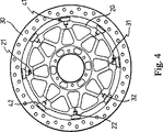
図4を参照するに、サポートベル20は、軸方向への動作によってブレーキバンド30に対して連結される。それにより、各突起32がハウジング22内に収容される。
Referring to FIG. 4, the
図5及び6を参照するに、各プレート42は、解放位置Bから固定位置Aに持ち来すために、半径方向内側にスライドさせられる。
Referring to FIGS. 5 and 6, each
最後に、プレート42を固定位置Aに固定するのに適合している固定手段45が操作され、これにより、プレートが所望しない半径方向へのスライドを防止する。
Finally, a fixing means 45 adapted to fix the
念のために述べると、各プレート42は、固定位置Aでは、羽根441及び442により、ハウジング22を画定するベルの部分を抱き込むものであり、従ってプレートの軸方向における移動を防止することに留意すべきである。同時に、スロット43は突起32を抱き込むことによって、プレート42の接線方向における移動を防止する。
As a precaution, each
再び図5を参照するに、プレート42の固定手段45は、長い方の羽根441に設けられた穴46と、この穴46に収容されるのに適合したピン47とを備えている。別の穴26がサポートベル20に設けられている。プレート42が固定位置Aにあるときは、各穴46および26の軸が互いに実質的に一致する。ピン47を挿入することによって、プレート42の半径方向における更なる移動が防止される。
Referring again to FIG. 5, the fixing means 45 of the
図示された実施形態によれば、ピンは、適宜ネジ山を設けた穴26にネジ込まれるネジ47によってもたらされる。また、各ネジ47をナットにネジ込むことは、たとえこの解決方法が、より多くの部品を必要とし、よって駆動連結の全体的な構造のより複雑化を伴うものであっても、如何なる場合でも設けることが可能である。
According to the illustrated embodiment, the pin is provided by a
図1は、本発明に係るブレーキディスク10を、車輪に対して取り付けられてはいないが使用形態において示している。
FIG. 1 shows a
当業者であれば理解できるように、前述の実施形態は従来技術に対して多くの利点をもたらすことが可能である。 As can be appreciated by one skilled in the art, the above-described embodiments can provide many advantages over the prior art.
まず、組立および分解操作の大幅な簡便性と迅速さが可能となる。実際、操作に関わる機械部品の数は、公知の解決方法に比べて極めて低減されている。 First, significant ease and speed of assembly and disassembly operations are possible. In fact, the number of mechanical parts involved in the operation is greatly reduced compared to known solutions.
更に、この解決方法は、突起32によってハウジング22の壁に加えられる接線方向の圧力によって、ブレーキトルクをバンド30からベル20に対して直接伝達することを可能にする。この解決方法は、更に、広い接触面を得ることを可能にし、その結果として、2つの特定要素間の接触に起因する局部的な応力を低減する。
Furthermore, this solution allows the brake torque to be transmitted directly from the
従って、この力の伝達においては、連結手段41は関与していない。例えばプレート42などの連結手段41は、の唯一の機能は、結合内においてバンド30とベル20との間で生じ得る軸方向の相対移動を制御する機能を有するだけである。これらの理由により、連結手段41は、類似した機能を有する公知の解決方法において使用される他の要素よりも、より簡素でより軽量となるように、寸法設定することが可能である。
Therefore, the connection means 41 is not involved in this force transmission. The only function of the connecting
実施可能で代替的な実施形態によれば、第1の接続手段31は、バンド30に設けられる複数のハウジングを備えている。同じ実施形態によれば、第2の接続手段21は、ベル20の外側に複数の半径方向の突起を備えている。各ハウジングは、突起の一つを収容するのに適合しており、ハウジング全体としては突起全体を収容するように構成される。
According to a possible alternative embodiment, the first connection means 31 comprises a plurality of housings provided on the
更に別の可能な実施形態によれば、第1および/または第2の接続手段の突起および/またはハウジングは、半径方向ではない方向に伸長している。 According to yet another possible embodiment, the projections and / or housings of the first and / or second connecting means extend in a direction that is not radial.
連結手段41の可能な実施形態によれば、連結手段41は、固定位置から解放位置へと位置を変えるのに、半径方向ではない方向に沿ってスライドする。
According to a possible embodiment of the connecting
別の実施形態によれば、連結手段41は、前述したものとは異なる固定手段45を備える。このような固定手段は、例えば、ネジ47に代えてリベットやリリースピンを備えているかも知れない。
According to another embodiment, the connecting
前述のブレーキディスクの実施形態に対して、当業者であれば、以下の請求項の範囲を逸脱することなく、偶発的なニーズを満足させるために、各要素の変形や調整および機能的に同等である別の要素との置換を実施することが可能である。実施可能である実施形態に属すると説明された各特徴を、別の実施形態における別の特徴とは別個に提供することが可能である。 For those embodiments of the brake disc described above, those skilled in the art will appreciate that the elements are modified, adjusted and functionally equivalent to satisfy incidental needs without departing from the scope of the following claims. It is possible to perform a substitution with another element that is Each feature that is described as belonging to an embodiment that can be implemented can be provided separately from another feature in another embodiment.
Claims (23)
前記第1の接続手段(31)を収容するのに適合した第2の接続手段(21)を備えるサポートベル(20)と、
複数の連結手段(41)であって、
当該連結手段の各々は、前記第1または第2の接続手段(31,21)のうち何れか一方とスライド式に連係され、固定位置(A)又は解放位置(B)の何れかに二者択一的にスライドするのに適合しており、
前記固定位置(A)では、前記連結手段(41)が、前記第1および前記第2の接続手段(31,21)を互いに対して固定して、前記ブレーキバンド(31)と前記サポートベル(21)との間における軸方向の相互移動を防止するように構成され、
前記解放位置(B)では、前記連結手段(41)は、前記第1および前記第2の接続手段(31,21)を互いに対して解放して、前記ブレーキバンド(30)と前記サポートベル(20)との間における軸方向の相互移動を許容するように構成されており、
前記連結手段(41)は、前記第1または前記第2の接続手段(31,21)の何れか一方に対し半径方向においてスライド式に連係させられ、且つ、前記固定位置(A)と前記解放位置(B)との間でスライドする、ように構成されている、
複数の連結手段と、
を備えている、ことを特徴とするディスクブレーキ用のディスク(10)。A brake band (30) comprising first connection means (31);
A support bell (20) comprising second connection means (21) adapted to receive said first connection means (31);
A plurality of connecting means (41),
The respective connection means, said being linked to the first or one and sliding of the second connecting means (31, 21), either the two parties of the fixed position (A) or released position (B) Suitable for sliding alternatively
In the fixed position (A), the connecting means (41) fixes the first and second connecting means (31, 21) with respect to each other, and the brake band (31) and the support bell ( 21) configured to prevent mutual axial movement with
In the release position (B), the coupling means (41) releases the first and second connection means (31, 21) with respect to each other so that the brake band (30) and the support bell ( is configured to permit mutual axial movement between the 20),
The connecting means (41) is slidably linked in a radial direction with respect to either the first or the second connecting means (31, 21), and is connected to the fixed position (A) and the release position. Configured to slide between position (B),
A plurality of connecting means;
A disc (10) for a disc brake, characterized by comprising:
− 第1の接続手段(31)を備えるブレーキバンド(30)を構成するステップと、
− 前記第1の接続手段(31)に対向するように構成された第2の接続手段(21)を備えるサポートベル(20)を構成するステップと、
− 前記第1または前記第2の接続手段(31,21)のうち何れか一方に対して連結手段(41)を半径方向においてスライド式に連係させるステップと、
− 前記連結手段(41)を解放位置(B)にさせるステップと、
− 前記ブレーキバンド(30)と前記サポートベル(20)との間において軸方向の相互動作を付与することによって前記第1及び前記第2の接続手段(31,21)を互いに対向させるステップと、
− 前記連結手段(41)を固定位置(A)にさせて、前記ブレーキバンド(31)と前記サポートベル(21)との間を軸方向において互いに固定するステップと、
を備えることを特徴とする方法。A method for assembling a brake disk according to claim 1, comprising:
-Configuring a brake band (30) comprising first connecting means (31);
-Configuring a support bell (20) comprising second connection means (21) configured to face said first connection means (31);
-Linking the connecting means (41) in a radial direction with respect to either the first or the second connecting means (31, 21);
-Bringing the connecting means (41) into the release position (B);
-Making the first and second connecting means (31, 21) face each other by imparting an axial movement between the brake band (30) and the support bell (20);
-The connecting means (41) in a fixed position (A) and fixing between the brake band (31) and the support bell (21) in the axial direction;
A method comprising the steps of:
Applications Claiming Priority (1)
| Application Number | Priority Date | Filing Date | Title |
|---|---|---|---|
| PCT/IT2005/000777 WO2007074488A1 (en) | 2005-12-29 | 2005-12-29 | Bell-band drive connection for disc brake |
Publications (2)
| Publication Number | Publication Date |
|---|---|
| JP2009522513A JP2009522513A (en) | 2009-06-11 |
| JP4977147B2 true JP4977147B2 (en) | 2012-07-18 |
Family
ID=36940249
Family Applications (1)
| Application Number | Title | Priority Date | Filing Date |
|---|---|---|---|
| JP2008548085A Active JP4977147B2 (en) | 2005-12-29 | 2005-12-29 | Drive connection of bell-band for disc brake |
Country Status (6)
| Country | Link |
|---|---|
| US (1) | US8387760B2 (en) |
| EP (1) | EP1966506B1 (en) |
| JP (1) | JP4977147B2 (en) |
| AT (1) | ATE438045T1 (en) |
| DE (1) | DE602005015775D1 (en) |
| WO (1) | WO2007074488A1 (en) |
Families Citing this family (8)
| Publication number | Priority date | Publication date | Assignee | Title |
|---|---|---|---|---|
| US7857111B1 (en) * | 2010-08-22 | 2010-12-28 | Ashima Ltd. | Reinforced disc brake rotor |
| JP5803739B2 (en) | 2012-02-28 | 2015-11-04 | サンスター技研株式会社 | brake disc |
| TWI532933B (en) * | 2014-12-05 | 2016-05-11 | 溫芫鋐 | Brake disk |
| US10190647B2 (en) | 2014-12-05 | 2019-01-29 | Yuan-Hung WEN | Brake disc |
| TWD172384S (en) * | 2015-03-17 | 2015-12-11 | 溫芫鋐 | Brake disc part |
| USD787995S1 (en) * | 2016-04-21 | 2017-05-30 | GRIMECA S.r.l. | Disc brake |
| US10100888B2 (en) * | 2016-05-16 | 2018-10-16 | Shimano Inc. | Bicycle disc brake rotor |
| IT201600097576A1 (en) | 2016-09-29 | 2018-03-29 | Freni Brembo Spa | disc for disc brake |
Family Cites Families (13)
| Publication number | Priority date | Publication date | Assignee | Title |
|---|---|---|---|---|
| JPS6018668Y2 (en) * | 1979-04-13 | 1985-06-06 | 住友金属工業株式会社 | brake disc assembly |
| JPH0210831Y2 (en) * | 1985-06-06 | 1990-03-16 | ||
| JPS6440726A (en) * | 1987-04-15 | 1989-02-13 | Yutaka Giken Co Ltd | Brake disc |
| JPS63259227A (en) | 1987-04-15 | 1988-10-26 | Yutaka Giken:Kk | Brake disc |
| JPH0612996Y2 (en) * | 1987-09-07 | 1994-04-06 | 日産自動車株式会社 | Four-wheel drive vehicle with viscous coupling |
| ITMI981136A1 (en) | 1998-05-21 | 1999-11-21 | Brembo Engineering S P A | BRAKE DISC WITH HIGH RESISTANCE TO WEAR AND THERMAL-MECHANICAL STRESS |
| JP2002227891A (en) * | 2001-01-29 | 2002-08-14 | Fuji Corporation:Kk | Disc brake rotor |
| US7104368B2 (en) * | 2002-01-14 | 2006-09-12 | Freni Brembo S.P.A | Disk-brake disk |
| DE60206058D1 (en) * | 2002-04-23 | 2005-10-13 | Freni Brembo Spa | DISC BEARING CONNECTION FOR A DISC BRAKE |
| US7374023B2 (en) * | 2002-05-27 | 2008-05-20 | Yutaka Giken Co., Ltd. | Floating-type brake disk |
| DE10351592B3 (en) * | 2003-11-05 | 2005-04-28 | Knorr Bremse Systeme | Brake disc especially for rail vehicles has friction ring centered and locked against rotation through slide elements each mounted in insert bore in hub or wheel disc |
| ITTO20030962A1 (en) | 2003-12-01 | 2005-06-02 | Skf Ab | CONNECTION OF A BRAKE ROTOR TO THE HUB OF THE WHEEL OF A MOTOR VEHICLE. |
| GB0405697D0 (en) | 2004-03-13 | 2004-04-21 | Ap Racing Ltd | Brake disc |
-
2005
- 2005-12-29 WO PCT/IT2005/000777 patent/WO2007074488A1/en active Application Filing
- 2005-12-29 DE DE602005015775T patent/DE602005015775D1/de active Active
- 2005-12-29 US US12/159,063 patent/US8387760B2/en active Active
- 2005-12-29 JP JP2008548085A patent/JP4977147B2/en active Active
- 2005-12-29 AT AT05850991T patent/ATE438045T1/en not_active IP Right Cessation
- 2005-12-29 EP EP05850991A patent/EP1966506B1/en active Active
Also Published As
| Publication number | Publication date |
|---|---|
| EP1966506A1 (en) | 2008-09-10 |
| DE602005015775D1 (en) | 2009-09-10 |
| WO2007074488A1 (en) | 2007-07-05 |
| EP1966506B1 (en) | 2009-07-29 |
| JP2009522513A (en) | 2009-06-11 |
| WO2007074488A8 (en) | 2007-08-30 |
| ATE438045T1 (en) | 2009-08-15 |
| US8387760B2 (en) | 2013-03-05 |
| US20080314703A1 (en) | 2008-12-25 |
Similar Documents
| Publication | Publication Date | Title |
|---|---|---|
| JP4977147B2 (en) | Drive connection of bell-band for disc brake | |
| JP2005299649A (en) | Device for axially holding blade to rotary disc of turbo machine | |
| US8292046B2 (en) | Wheel carrier for vehicles with a disc brake | |
| JP2012025393A (en) | Releasably locking device for bicycle component, and clamping element for the same | |
| JP2006010079A5 (en) | ||
| JPH08219202A (en) | Brake disc for disc brake | |
| JP2006234163A (en) | Brake for wheel with brake disk split into fan shape sector | |
| US20070131515A1 (en) | Friction device for a clutch, in particular for a motor vehicle | |
| JP2006083916A (en) | Floating caliper type disk brake | |
| US20190257377A1 (en) | Opposed piston type disc brake | |
| JPS6037427A (en) | Disc brake | |
| JP2004511737A (en) | Disc brake disc | |
| GB2481112A (en) | Internally ventilated disc brake having two friction rings of a first material and an inner part of a second material | |
| JPS6049127A (en) | Clutch mechanism and pressure plate therefor | |
| JP2018031472A (en) | Gear shift device for automobile transmission | |
| KR102060340B1 (en) | Coupling device | |
| FR2662765A1 (en) | Clutch with several friction discs, particularly for motor vehicles | |
| JP6417229B2 (en) | Jig for aligning upper half of turbine casing | |
| WO2015119262A1 (en) | Disk brake device | |
| JP5960535B2 (en) | Cable connection device for drum brake type electric parking brake device | |
| JP4754543B2 (en) | Multi-disc type disc brake device and its assembling method | |
| KR20160094139A (en) | Modular actuator and ball in ramp brake caliper type parking brake system | |
| JP2018197554A (en) | Electric drum brake | |
| JP5783856B2 (en) | Floating brake disc | |
| US20040140173A1 (en) | Pressure plate assembly for a friction clutch |
Legal Events
| Date | Code | Title | Description |
|---|---|---|---|
| A131 | Notification of reasons for refusal |
Free format text: JAPANESE INTERMEDIATE CODE: A131 Effective date: 20110816 |
|
| A977 | Report on retrieval |
Free format text: JAPANESE INTERMEDIATE CODE: A971007 Effective date: 20110818 |
|
| A601 | Written request for extension of time |
Free format text: JAPANESE INTERMEDIATE CODE: A601 Effective date: 20111115 |
|
| A602 | Written permission of extension of time |
Free format text: JAPANESE INTERMEDIATE CODE: A602 Effective date: 20111122 |
|
| A601 | Written request for extension of time |
Free format text: JAPANESE INTERMEDIATE CODE: A601 Effective date: 20111216 |
|
| A602 | Written permission of extension of time |
Free format text: JAPANESE INTERMEDIATE CODE: A602 Effective date: 20111226 |
|
| A521 | Request for written amendment filed |
Free format text: JAPANESE INTERMEDIATE CODE: A523 Effective date: 20120113 |
|
| TRDD | Decision of grant or rejection written | ||
| A01 | Written decision to grant a patent or to grant a registration (utility model) |
Free format text: JAPANESE INTERMEDIATE CODE: A01 Effective date: 20120403 |
|
| A01 | Written decision to grant a patent or to grant a registration (utility model) |
Free format text: JAPANESE INTERMEDIATE CODE: A01 |
|
| A61 | First payment of annual fees (during grant procedure) |
Free format text: JAPANESE INTERMEDIATE CODE: A61 Effective date: 20120413 |
|
| R150 | Certificate of patent or registration of utility model |
Free format text: JAPANESE INTERMEDIATE CODE: R150 Ref document number: 4977147 Country of ref document: JP Free format text: JAPANESE INTERMEDIATE CODE: R150 |
|
| FPAY | Renewal fee payment (event date is renewal date of database) |
Free format text: PAYMENT UNTIL: 20150420 Year of fee payment: 3 |
|
| R250 | Receipt of annual fees |
Free format text: JAPANESE INTERMEDIATE CODE: R250 |
|
| R250 | Receipt of annual fees |
Free format text: JAPANESE INTERMEDIATE CODE: R250 |
|
| R250 | Receipt of annual fees |
Free format text: JAPANESE INTERMEDIATE CODE: R250 |
|
| R250 | Receipt of annual fees |
Free format text: JAPANESE INTERMEDIATE CODE: R250 |
|
| R250 | Receipt of annual fees |
Free format text: JAPANESE INTERMEDIATE CODE: R250 |
|
| R250 | Receipt of annual fees |
Free format text: JAPANESE INTERMEDIATE CODE: R250 |
|
| R250 | Receipt of annual fees |
Free format text: JAPANESE INTERMEDIATE CODE: R250 |
|
| R250 | Receipt of annual fees |
Free format text: JAPANESE INTERMEDIATE CODE: R250 |
|
| R250 | Receipt of annual fees |
Free format text: JAPANESE INTERMEDIATE CODE: R250 |
|
| S533 | Written request for registration of change of name |
Free format text: JAPANESE INTERMEDIATE CODE: R313533 |
|
| R350 | Written notification of registration of transfer |
Free format text: JAPANESE INTERMEDIATE CODE: R350 |
|
| R250 | Receipt of annual fees |
Free format text: JAPANESE INTERMEDIATE CODE: R250 |