EP1966506B1 - Bell-band drive connection for disc brake - Google Patents
Bell-band drive connection for disc brake Download PDFInfo
- Publication number
- EP1966506B1 EP1966506B1 EP05850991A EP05850991A EP1966506B1 EP 1966506 B1 EP1966506 B1 EP 1966506B1 EP 05850991 A EP05850991 A EP 05850991A EP 05850991 A EP05850991 A EP 05850991A EP 1966506 B1 EP1966506 B1 EP 1966506B1
- Authority
- EP
- European Patent Office
- Prior art keywords
- connecting means
- braking
- disc
- band
- bell
- Prior art date
- Legal status (The legal status is an assumption and is not a legal conclusion. Google has not performed a legal analysis and makes no representation as to the accuracy of the status listed.)
- Active
Links
- 230000008878 coupling Effects 0.000 claims abstract description 32
- 238000010168 coupling process Methods 0.000 claims abstract description 32
- 238000005859 coupling reaction Methods 0.000 claims abstract description 32
- 238000000034 method Methods 0.000 claims description 9
- 230000008859 change Effects 0.000 claims description 2
- 230000008901 benefit Effects 0.000 description 6
- 230000005540 biological transmission Effects 0.000 description 2
- 238000004519 manufacturing process Methods 0.000 description 2
- 238000005266 casting Methods 0.000 description 1
- 230000004048 modification Effects 0.000 description 1
- 238000012986 modification Methods 0.000 description 1
Images
Classifications
-
- F—MECHANICAL ENGINEERING; LIGHTING; HEATING; WEAPONS; BLASTING
- F16—ENGINEERING ELEMENTS AND UNITS; GENERAL MEASURES FOR PRODUCING AND MAINTAINING EFFECTIVE FUNCTIONING OF MACHINES OR INSTALLATIONS; THERMAL INSULATION IN GENERAL
- F16D—COUPLINGS FOR TRANSMITTING ROTATION; CLUTCHES; BRAKES
- F16D65/00—Parts or details
- F16D65/02—Braking members; Mounting thereof
- F16D65/12—Discs; Drums for disc brakes
-
- F—MECHANICAL ENGINEERING; LIGHTING; HEATING; WEAPONS; BLASTING
- F16—ENGINEERING ELEMENTS AND UNITS; GENERAL MEASURES FOR PRODUCING AND MAINTAINING EFFECTIVE FUNCTIONING OF MACHINES OR INSTALLATIONS; THERMAL INSULATION IN GENERAL
- F16D—COUPLINGS FOR TRANSMITTING ROTATION; CLUTCHES; BRAKES
- F16D65/00—Parts or details
- F16D65/02—Braking members; Mounting thereof
- F16D2065/13—Parts or details of discs or drums
- F16D2065/1304—Structure
- F16D2065/1316—Structure radially segmented
-
- F—MECHANICAL ENGINEERING; LIGHTING; HEATING; WEAPONS; BLASTING
- F16—ENGINEERING ELEMENTS AND UNITS; GENERAL MEASURES FOR PRODUCING AND MAINTAINING EFFECTIVE FUNCTIONING OF MACHINES OR INSTALLATIONS; THERMAL INSULATION IN GENERAL
- F16D—COUPLINGS FOR TRANSMITTING ROTATION; CLUTCHES; BRAKES
- F16D65/00—Parts or details
- F16D65/02—Braking members; Mounting thereof
- F16D2065/13—Parts or details of discs or drums
- F16D2065/134—Connection
- F16D2065/1356—Connection interlocking
- F16D2065/136—Connection interlocking with relative movement radially
-
- F—MECHANICAL ENGINEERING; LIGHTING; HEATING; WEAPONS; BLASTING
- F16—ENGINEERING ELEMENTS AND UNITS; GENERAL MEASURES FOR PRODUCING AND MAINTAINING EFFECTIVE FUNCTIONING OF MACHINES OR INSTALLATIONS; THERMAL INSULATION IN GENERAL
- F16D—COUPLINGS FOR TRANSMITTING ROTATION; CLUTCHES; BRAKES
- F16D65/00—Parts or details
- F16D65/02—Braking members; Mounting thereof
- F16D2065/13—Parts or details of discs or drums
- F16D2065/134—Connection
- F16D2065/1392—Connection elements
Definitions
- the object of the present invention is a braking disc having an improved drive connection between the support bell and the braking band.
- This technical solution involves considerable advantages. First of all, it allows the braking band, which may reach high temperatures during the braking, to expand without being affected by any constraint imposed by the support bell. Moreover, this solution allows the two pieces to be manufactured in materials which are different from one another and such as to optimize the braking disc overall performance.
- This solution involves the use of a so-called drive connection, i.e. of further means adapted to structurally connect the bell and the band, thus ensuring the braking torque transmission and the desired backlashes or gaps.
- the object of the present invention is to devise and provide a braking disc having a drive connection between the support bell and the braking band which allows to overcome the drawbacks cited above with reference to the prior art.
- the task of the present invention is to provide a drive connection which allows a high assembling speed.
- Another task of the present invention is to provide a drive connection which allows the number of mechanical pieces used in the connection between the bell and the band to be reduced.
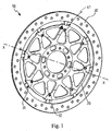
- Fig. 1 shows an overall perspective view of a braking disc according to the invention
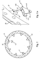
- Fig. 2 shows a braking band upon the assembly of the braking disc according to the invention
- Fig. 2.a shows a detail of the braking band from Fig. 2 upon assembly
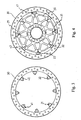
- Fig. 3 shows the braking band from Fig. 2 upon assembly, as seen from the opposite side relative to the one from Fig. 2 ;
- Fig. 4 shows a braking band and a support bell upon assembly of the braking disc according to the invention
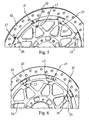
- Fig. 5 shows a detail of the drive connection between the bell and the band upon assembly
- Fig. 6 shows the detail from Fig. 5 , as seen from the opposite side relative to the one from Fig. 5 .
- a braking disc has been generally indicated with 10.
- the braking disc 10 comprises a support bell (or simply bell) indicated with 20 and a braking band (or simply band) indicated with 30.
- the braking disc 10 univocally defines an X-axis.
- the direction of any straight line parallel to X-axis is defined as "axial” herein below.
- the direction of a half line having its origin in X-axis and perpendicular to the latter is defined as “radial” herein below.
- the direction of any straight line tangent to a circumference being centred on X-axis and lying in a plane perpendicular to the latter is defined as “tangential” herein below.
- the braking band 30 comprises first connecting means 31.
- the braking band 30 comprises a plurality of first connecting means 31.
- the support bell 20 comprises second connecting means 21 adapted to face said first connecting means 31.
- the support bell 20 comprises a plurality of second connecting means 21 adapted to face the plurality of first connecting means 31 of the band 30.
- the braking disc 10 further comprises coupling means 41, each of which is adapted to be slidingly associated either to said first connecting means 31 or to said second connecting means 21.
- the braking disc 10 comprises a plurality of coupling means 41.
- Each of the coupling means 41 is further adapted to alternatively take either a fastening position (which has been indicated with A in Figs. 5 and 6 ) or a release position (which has been indicated with B in Figs. 5 and 6 ).
- the coupling means 41 are adapted to mutually fasten the first and second connecting means, 31 and 21 respectively, such as to mutually fasten the braking band 30 and the support bell 20.
- the constraint between the braking band 30 and support bell 20 is meant to be such that a relative movement in the radial direction is however allowed. In fact, this movement allowance is the greatest functional advantage of built-up braking discs as compared with monolithic braking discs.
- the coupling means 41 are adapted to mutually release the first and second connecting means, 31 and 21 respectively, such as to allow a mutual movement between the braking band 30 and support bell 20.
- the first connecting means 31 comprise a plurality of inner radial protrusions 32 of the band 30.
- the second connecting means 21 comprise a plurality of housings 22 provided on the bell 20.
- Each of the housings 22 is adapted to accommodate one of the protrusions 32 and the housings 22 on the whole are adapted to accommodate the protrusions 32 on the whole.
- the protrusions 32 and housings 22 are shaped such that they can be coupled with one another by an axial relative movement between the band 30 and bell 20.
- the coupling means 41 comprise a plurality of plates 42. Particularly, a plate 42 which is bent such as to form two wings of different length connected with each other by a connecting portion 440 being substantially perpendicular thereto is shown in Fig. 2.a : a first longer wing 441 and a second shorter wing 442.
- Each plate 42 further comprises a slot 43 on the top of the coupling portion 440.
- the slot 43 of each plate 42 is capable of accommodating a protrusion 32. Therefore, the plate 42 may be fitted on the protrusion 32 and may be caused to slide along the latter in the radial direction. These movements have been schematically indicated by arrow C from Fig. 2.a .
- Each plate 42 is capable of radially sliding between the fastening position A and the release position B, both indicated in Figs. 5 and 6 , after it has been fitted on a protrusion 32.
- Each plate 42 further comprises fastening means 45 adapted to fasten the latter in a desired position, thus preventing unwanted sliding of the plate 42 in the axial and/or radial directions.
- a braking band 30 comprising first connecting means 31 and a support bell 20 comprising second connecting means 21 adapted to face the first connecting means 31 are required to be preset.
- the coupling means 41 require to be slidingly associated to one of either the first or second connecting means, either 31 or 21 respectively.
- the coupling means 41 have to take a release position B, therefore a mutual movement in the axial direction between the braking band 30 and support bell 20 requires to be imposed.
- the first and second connecting means 31 and 21 face one another.
- the coupling means 41 have to take a fastening position A, such as to mutually fasten the braking band 31 and support bell 21 in the axial direction.
- a plate 42 is fitted on each of the protrusions 32 of the braking band 30. In this step, it is necessary to maintain the same orientation with all the plates 42 so that the first longer wings 441 are all on the same side of the braking band 30 and, accordingly, the second shorter wings 442 are all on the opposite side of the braking band 30.
- the plates 42 are radially thrust to the outside, until they reach the release position B.
- each protrusion 32 is accommodated in a housing 22.
- each plate 42 is caused to radially slide inwardly, in order to bring the latter from the release position B to the fastening position A.
- each plate 42 in the fastening position A, embraces with the wings 441 and 442 the portion of bell which defines the housing 22 thus preventing the plate axial movements.
- the slot 43 embraces the protrusion 32, thus preventing the tangential movements of the plate 42.
- the fastening means 45 of the plate 42 comprise a hole 46 provided on the longer wing 441 and a pin 47 adapted to be accommodated in the hole 46.
- a further hole 26 is provided on the support bell 20.
- the pin is provided by means of a screw 47 which is screwed into the hole 26 being suitably threaded. It can be provided in any case that each screw 47 is screwed into a nut, even if this solution involves a larger number of pieces and hence a higher drive connection overall complication.
- Fig. 1 shows the braking disc 10 according to the invention in the use configuration thereof, without the mounting on the vehicle wheel.
- this solution allows the braking torque to be directly transmitted from the band 30 to the bell 20, by means of the pressure applied in the tangential direction by the protrusions 32 on the walls of the housings 22.
- This solution further allows to obtain a wide contact surface, with the subsequent decrease of the local stresses due to the contact between the two specific components.
- the coupling means 41 are not involved.
- the coupling means 41 for example the plates 42, have the only function of controlling the relative movements which could occur between the band 30 and bell 20 in the axial direction within bonds.
- the coupling means 41 can be sized such as to be simpler and lighter than other elements used in the known solutions with similar functions.
- the first connecting means 31 comprise a plurality of housings provided on the band 30.
- the second connecting means 21 comprise a plurality of radial protrusions outside the bell 20. Each of the housings is adapted to accommodate one of the protrusions and the housings on the whole are adapted to accommodate the protrusions on the whole.
- the protrusions and/or the housings of the first and/or second connecting means extend in a direction which is different from the radial direction.
- the coupling means 41 slide along a direction which is different from the radial direction, in order to change from the fastening position to the release position.
- the coupling means 41 comprise fastening means 45 which are different from the ones described above.
- the fastening means may comprise either a rivet or a release pin, instead of the screw 47.
Abstract
Description
- . The object of the present invention is a braking disc having an improved drive connection between the support bell and the braking band.
- . In the disc brake field, manufacturing of the braking disc in two separate pieces is known and appreciated: the support bell and the braking band.
- . This technical solution involves considerable advantages. First of all, it allows the braking band, which may reach high temperatures during the braking, to expand without being affected by any constraint imposed by the support bell. Moreover, this solution allows the two pieces to be manufactured in materials which are different from one another and such as to optimize the braking disc overall performance.
- . The solution selected for the structural connection between the band and the bell also decisively contributes to obtain some advantages.
- . For example, it is known to obtain the whole braking disc during a single manufacturing process, though using different materials for the band and the bell. This result can be achieved for example by a co-casting process.
- . It is also known to provide the braking band and the support bell independently from each other in order to subsequently form the braking disc only upon assembling.
- . This solution involves the use of a so-called drive connection, i.e. of further means adapted to structurally connect the bell and the band, thus ensuring the braking torque transmission and the desired backlashes or gaps.
- . In some specific fields, for example within the field of the high-performance and competition motorcycles, the drive connections which ensure a considerably easy mounting, besides ensuring all the above advantages, are particularly appreciated.
- . These drive connections further allow the only braking band to be quickly replaced, for example if the latter is worn, with no need for the support bell to be also replaced.
- . It is known from
US 2005/0145452 a braking disc in which the band and the bell are assembled by means of an axial movement allowing to couple the bell axial protrusions with the band inner radial protrusions. The assembling ends with the application of an elastic retainer which can be locked in position for example by means of riveting. This solution, though requiring a small number of pieces, does not allow an easy assembling of the braking disc and above all it does not allow the disassembling thereof after it has been assembled. - . It is also known from
PCT WO 2005/088152 a drive connection which uses a plurality of plates, each of which connects a band inner radial protrusion to a bell outer radial protrusion. Each of said plates is fastened by means of two screw-nut screw couplings. A large number of pieces to be assembled and, accordingly, a high complexity of the assembling and disassembling operations of the braking disc derive from this technical characteristic. - . The object of the present invention is to devise and provide a braking disc having a drive connection between the support bell and the braking band which allows to overcome the drawbacks cited above with reference to the prior art.
- . Particularly, the task of the present invention is to provide a drive connection which allows a high assembling speed.
- . Another task of the present invention is to provide a drive connection which allows the number of mechanical pieces used in the connection between the bell and the band to be reduced.
- . This object and these tasks are achieved by means of a braking disc in accordance with claim 1 and by means of a method of use in accordance with
claim 21. - . Further characteristics and the advantages of the braking disc according to the invention will be understood from the description of preferred exemplary embodiments as set forth herein below, which are given by way of indicative and non-limiting example, with reference to the annexed figures, in which:
- .
Fig. 1 shows an overall perspective view of a braking disc according to the invention; - .
Fig. 2 shows a braking band upon the assembly of the braking disc according to the invention; - .
Fig. 2.a shows a detail of the braking band fromFig. 2 upon assembly; - .
Fig. 3 shows the braking band fromFig. 2 upon assembly, as seen from the opposite side relative to the one fromFig. 2 ; - .
Fig. 4 shows a braking band and a support bell upon assembly of the braking disc according to the invention; - .
Fig. 5 shows a detail of the drive connection between the bell and the band upon assembly; - .
Fig. 6 shows the detail fromFig. 5 , as seen from the opposite side relative to the one fromFig. 5 . - . With reference to said figures, a braking disc has been generally indicated with 10. The
braking disc 10 comprises a support bell (or simply bell) indicated with 20 and a braking band (or simply band) indicated with 30. - . The
braking disc 10 univocally defines an X-axis. The direction of any straight line parallel to X-axis is defined as "axial" herein below. The direction of a half line having its origin in X-axis and perpendicular to the latter is defined as "radial" herein below. Finally, the direction of any straight line tangent to a circumference being centred on X-axis and lying in a plane perpendicular to the latter is defined as "tangential" herein below. - . The
braking band 30 comprises first connecting means 31. In accordance with a preferred embodiment, thebraking band 30 comprises a plurality of first connecting means 31. - . The
support bell 20 comprises second connecting means 21 adapted to face said first connectingmeans 31. In accordance with a preferred embodiment, thesupport bell 20 comprises a plurality of second connecting means 21 adapted to face the plurality of first connectingmeans 31 of theband 30. - . The
braking disc 10 further comprises coupling means 41, each of which is adapted to be slidingly associated either to said first connectingmeans 31 or to said second connectingmeans 21. In accordance with an embodiment, thebraking disc 10 comprises a plurality of coupling means 41. - . Each of the coupling means 41 is further adapted to alternatively take either a fastening position (which has been indicated with A in
Figs. 5 and 6 ) or a release position (which has been indicated with B inFigs. 5 and 6 ). - . In the fastening position A the coupling means 41 are adapted to mutually fasten the first and second connecting means, 31 and 21 respectively, such as to mutually fasten the
braking band 30 and thesupport bell 20. - . Here and herein below, the constraint between the
braking band 30 andsupport bell 20 is meant to be such that a relative movement in the radial direction is however allowed. In fact, this movement allowance is the greatest functional advantage of built-up braking discs as compared with monolithic braking discs. - . On the other hand, in the release position B, the coupling means 41 are adapted to mutually release the first and second connecting means, 31 and 21 respectively, such as to allow a mutual movement between the
braking band 30 andsupport bell 20. - . In accordance with the embodiment such as illustrated in the annexed figures, the first connecting
means 31 comprise a plurality of innerradial protrusions 32 of theband 30. - . In accordance with the embodiment such as shown in the annexed figures, the second connecting
means 21 comprise a plurality ofhousings 22 provided on thebell 20. Each of thehousings 22 is adapted to accommodate one of theprotrusions 32 and thehousings 22 on the whole are adapted to accommodate theprotrusions 32 on the whole. - . In accordance with this embodiment, the
protrusions 32 andhousings 22 are shaped such that they can be coupled with one another by an axial relative movement between theband 30 andbell 20. - . In accordance with the embodiment such as illustrated in
Fig. 2.a in the annexed figures, the coupling means 41 comprise a plurality ofplates 42. Particularly, aplate 42 which is bent such as to form two wings of different length connected with each other by a connectingportion 440 being substantially perpendicular thereto is shown inFig. 2.a : a firstlonger wing 441 and a secondshorter wing 442. - . Each
plate 42 further comprises aslot 43 on the top of thecoupling portion 440. Theslot 43 of eachplate 42 is capable of accommodating aprotrusion 32. Therefore, theplate 42 may be fitted on theprotrusion 32 and may be caused to slide along the latter in the radial direction. These movements have been schematically indicated by arrow C fromFig. 2.a . Eachplate 42 is capable of radially sliding between the fastening position A and the release position B, both indicated inFigs. 5 and 6 , after it has been fitted on aprotrusion 32. - . Each
plate 42 further comprises fastening means 45 adapted to fasten the latter in a desired position, thus preventing unwanted sliding of theplate 42 in the axial and/or radial directions. - . It will be schematically described herein below an embodiment of the method for assembling a braking disc comprising a drive connection according to the invention.
- . First of all, a
braking band 30 comprising first connectingmeans 31 and asupport bell 20 comprising second connecting means 21 adapted to face the first connectingmeans 31 are required to be preset. - . Then, the coupling means 41 require to be slidingly associated to one of either the first or second connecting means, either 31 or 21 respectively.
- . Accordingly, the coupling means 41 have to take a release position B, therefore a mutual movement in the axial direction between the
braking band 30 andsupport bell 20 requires to be imposed. Thereby, the first and second connectingmeans - . Finally, the coupling means 41 have to take a fastening position A, such as to mutually fasten the
braking band 31 andsupport bell 21 in the axial direction. - . It will be described herein below another embodiment of the method for assembling a braking disc comprising a drive connection according to the invention, in the embodiment such as shown in the annexed figures.
- . With reference to
Figs. 2 and 2.a , aplate 42 is fitted on each of theprotrusions 32 of thebraking band 30. In this step, it is necessary to maintain the same orientation with all theplates 42 so that the firstlonger wings 441 are all on the same side of thebraking band 30 and, accordingly, the secondshorter wings 442 are all on the opposite side of thebraking band 30. - . With reference to
Fig. 3 , theplates 42 are radially thrust to the outside, until they reach the release position B. - . With reference to
Fig. 4 , thesupport bell 20 is coupled with thebraking band 30 by an axial movement. Thereby, eachprotrusion 32 is accommodated in ahousing 22. - . With reference to
Figs. 5 and 6 , eachplate 42 is caused to radially slide inwardly, in order to bring the latter from the release position B to the fastening position A. - . Finally, the fastening means 45 adapted to fasten the
plate 42 in the fastening position A are operated, thus preventing unwanted sliding thereof in the radial direction. - . For completeness reasons, it shall be noted now that each
plate 42, in the fastening position A, embraces with thewings housing 22 thus preventing the plate axial movements. At the same time, theslot 43 embraces theprotrusion 32, thus preventing the tangential movements of theplate 42. - . With reference again to
Fig. 5 , the fastening means 45 of theplate 42 comprise ahole 46 provided on thelonger wing 441 and apin 47 adapted to be accommodated in thehole 46. Afurther hole 26 is provided on thesupport bell 20. When theplate 42 takes the fastening position A, the axes of theholes pin 47 prevents each further movement of theplate 42 in the radial direction. - . In accordance with the shown embodiment, the pin is provided by means of a
screw 47 which is screwed into thehole 26 being suitably threaded. It can be provided in any case that eachscrew 47 is screwed into a nut, even if this solution involves a larger number of pieces and hence a higher drive connection overall complication. - .
Fig. 1 shows thebraking disc 10 according to the invention in the use configuration thereof, without the mounting on the vehicle wheel. - . As will be now understood by a skilled operator, the embodiment described above allows to obtain many advantages compared to the prior art.
- . First of all, it allows much simplicity and speed for the assembling and disassembling operations. In fact, the number of mechanical pieces involved in the operations is extremely reduced compared to the known solutions.
- . Furthermore, this solution allows the braking torque to be directly transmitted from the
band 30 to thebell 20, by means of the pressure applied in the tangential direction by theprotrusions 32 on the walls of thehousings 22. This solution further allows to obtain a wide contact surface, with the subsequent decrease of the local stresses due to the contact between the two specific components. - . Therefore, in this force transmission, the coupling means 41 are not involved. The coupling means 41, for example the
plates 42, have the only function of controlling the relative movements which could occur between theband 30 andbell 20 in the axial direction within bonds. For this reasons, the coupling means 41 can be sized such as to be simpler and lighter than other elements used in the known solutions with similar functions. - . In accordance with a possible alternative embodiment, the first connecting
means 31 comprise a plurality of housings provided on theband 30. In accordance with the same embodiment, the second connectingmeans 21 comprise a plurality of radial protrusions outside thebell 20. Each of the housings is adapted to accommodate one of the protrusions and the housings on the whole are adapted to accommodate the protrusions on the whole. - . In accordance with another possible embodiment, the protrusions and/or the housings of the first and/or second connecting means extend in a direction which is different from the radial direction.
- . In accordance with a possible embodiment of the coupling means 41, they slide along a direction which is different from the radial direction, in order to change from the fastening position to the release position.
- . In accordance with another embodiment, the coupling means 41 comprise fastening means 45 which are different from the ones described above. For example, the fastening means may comprise either a rivet or a release pin, instead of the
screw 47. - . To the above-mentioned embodiments of the braking disc, those skilled in the art, in order to satisfy contingent needs, will be able to carry out modifications, adjustments and replacements of elements with other elements being functionally equivalent thereto, without departing from the scope of the claims below. Each of the characteristics described as belonging to a possible embodiment may be provided independently from the other characteristics in other embodiments.
Claims (26)
- A disc (10) for disc brake comprising:a braking band (30) comprising first connecting means (31) ;a support bell (20) comprising second connecting means (21) adapted to face said first connecting means (31); anda plurality of coupling means (41), characterised in that each of said coupling means isslidingly associated to one of either said first or said second connecting means (31, 21) andadapted to alternatively take either a fastening position (A) or a release position (B), wherein:said coupling means (41), in said fastening position (A), are adapted to mutually fasten said first and said second connecting means (31, 21) such as to mutually fasten said braking band (31) and said support bell (21) in the axial direction; andsaid coupling means (41), in said release position (B), are adapted to mutually release said first and said second connecting means (31, 21) such as to allow a mutual movement between said braking band (30) and said support bell (20) in the axial direction.
- The braking disc (10) according to the preceding claim, wherein said coupling means (41) are slidingly associated either to said first or to said second connecting means (31, 21) in the radial direction.
- The braking disc (10) according to any preceding claim, wherein the first connecting means (31) comprise a plurality of inward radial protrusions (32) of the band (30).
- The braking disc (10) according to the preceding claim, wherein the second connecting means (21) comprise a plurality of housings (22) provided on the bell (20).
- The braking disc (10) according to the preceding claim, wherein each of the housings (22) is adapted to accommodate one of the protrusions (32) and the housings (22) on the whole are adapted to accommodate the protrusions (32) on the whole.
- The braking disc (10) according to claim 4, wherein the protrusions (32) and the housings (22) are shaped such as to be coupled with one another by a relative movement in the axial direction between the band (30) and bell (20).
- The braking disc (10) according to any preceding claim, wherein the coupling means (41) comprise a plurality of plates (42).
- The braking disc (10) according to the preceding claim, wherein each of said plates (42) is bent such as to form two wings (441, 442) connected to each other by a connecting portion (440) being substantially perpendicular thereto.
- The braking disc (10) according to the preceding claim, wherein said plate (42) comprises a first longer wing (441) and a second shorter wing (442).
- The braking disc (10) according to claim 8 or 9, wherein said plate (42) further comprises a slot (43) on the top of the connecting portion (440), said slot (43) being adapted to accommodate a protrusion (32).
- The braking disc (10) according to any preceding claim, wherein each plate (42) is adapted to be fitted on a protrusion (32) and to slide along the latter in the radial direction between the fastening position (A) and release position (B).
- The braking disc (10) according to any preceding claim, wherein each plate (42) further comprises fastening means (45) adapted to fasten said plate (42) in a desired position, thus preventing unwanted sliding thereof.
- The braking disc (10) according to any preceding claim, wherein said fastening means (45) of the plate (42) comprise a first hole (46) provided on the longer wing (441), a second hole (26) provided on the support bell (20) and a pin (47) adapted to be accommodated in said first and second holes (46, 26).
- The braking disc (10) according to the preceding claim, wherein said second hole (26) is threaded and said pin comprises a screw (47) adapted to be screwed into the second hole (26).
- The braking disc (10) according to claim 13, wherein said fastening means (45) comprise either a rivet or a release pin.
- The braking disc (10) according to claim 1, wherein the first connecting means (31) comprise a plurality of housings provided on the band (30), and the second connecting means (21) comprise a plurality of outward radial protrusions on the bell (20), each of the housings being adapted to accommodate one of the protrusions and the housings on the whole being adapted to accommodate the protrusions on the whole.
- The braking disc (10) according to claim 1, wherein said first and/or said second connecting means (21, 31) extend in a direction which is different from the radial direction.
- The braking disc (10) according to claim 1, wherein said coupling means (41) slide along a direction which is different from the radial direction, in order to change from the fastening position (A) to the release position (B) and vice versa.
- A disc brake comprising a disc according to any preceding claim.
- A vehicle comprising a disc brake according to the preceding claim.
- A method for assembling a braking disc according to claim 1, comprising the steps of:- arranging a braking band (30) comprising first connecting means (31);- arranging a support bell (20) comprising second connecting means (21) adapted to face said first connecting means (31);- slidingly associating coupling means (41) to one of either said first or said second connecting means (31, 21);- causing said coupling means (41) to take a release position (B);- imposing a mutual movement between said braking band (30) and said support bell (20) in the axial direction such as to face said first and said second connecting means (31, 21) one another;- causing said coupling means (41) to take a fastening position (A) such as to mutually fasten said braking band (31) and said support bell (21) in the axial direction.
- The method according to the preceding claim, wherein said step of slidingly associating coupling means (41) to one of either said first or said second connecting means (31, 21), comprises the step of fitting a plate (42) on each protrusion (32).
- The method according to the preceding claim, wherein said step of causing said coupling means (41) to take a release position (B) comprises the step of causing each of said plates (42) to radially slide to the outside.
- The method according to any claim 21 to 23, wherein the step of facing said first and said second connecting means (31, 21) each other comprises the step of housing each protrusion (32) in a housing (22).
- The method according to any claim 21 to 24, wherein the step of causing said coupling means (41) to take a fastening position (A) comprises the step of causing each of said plates (42) to radially slide inwardly.
- The method according to any claim 21 to 25, further comprising the step of operating fastening means (45) adapted to fasten the plate (42) in the fastening position (A), thus preventing unwanted sliding thereof.
Applications Claiming Priority (1)
| Application Number | Priority Date | Filing Date | Title |
|---|---|---|---|
| PCT/IT2005/000777 WO2007074488A1 (en) | 2005-12-29 | 2005-12-29 | Bell-band drive connection for disc brake |
Publications (2)
| Publication Number | Publication Date |
|---|---|
| EP1966506A1 EP1966506A1 (en) | 2008-09-10 |
| EP1966506B1 true EP1966506B1 (en) | 2009-07-29 |
Family
ID=36940249
Family Applications (1)
| Application Number | Title | Priority Date | Filing Date |
|---|---|---|---|
| EP05850991A Active EP1966506B1 (en) | 2005-12-29 | 2005-12-29 | Bell-band drive connection for disc brake |
Country Status (6)
| Country | Link |
|---|---|
| US (1) | US8387760B2 (en) |
| EP (1) | EP1966506B1 (en) |
| JP (1) | JP4977147B2 (en) |
| AT (1) | ATE438045T1 (en) |
| DE (1) | DE602005015775D1 (en) |
| WO (1) | WO2007074488A1 (en) |
Families Citing this family (8)
| Publication number | Priority date | Publication date | Assignee | Title |
|---|---|---|---|---|
| US7857111B1 (en) * | 2010-08-22 | 2010-12-28 | Ashima Ltd. | Reinforced disc brake rotor |
| JP5803739B2 (en) | 2012-02-28 | 2015-11-04 | サンスター技研株式会社 | brake disc |
| TWI532933B (en) * | 2014-12-05 | 2016-05-11 | 溫芫鋐 | Brake disk |
| US10190647B2 (en) | 2014-12-05 | 2019-01-29 | Yuan-Hung WEN | Brake disc |
| TWD172384S (en) * | 2015-03-17 | 2015-12-11 | 溫芫鋐 | Brake disc part |
| USD787995S1 (en) * | 2016-04-21 | 2017-05-30 | GRIMECA S.r.l. | Disc brake |
| US10100888B2 (en) * | 2016-05-16 | 2018-10-16 | Shimano Inc. | Bicycle disc brake rotor |
| IT201600097576A1 (en) | 2016-09-29 | 2018-03-29 | Freni Brembo Spa | disc for disc brake |
Family Cites Families (13)
| Publication number | Priority date | Publication date | Assignee | Title |
|---|---|---|---|---|
| JPS6018668Y2 (en) * | 1979-04-13 | 1985-06-06 | 住友金属工業株式会社 | brake disc assembly |
| JPH0210831Y2 (en) * | 1985-06-06 | 1990-03-16 | ||
| JPS6440726A (en) * | 1987-04-15 | 1989-02-13 | Yutaka Giken Co Ltd | Brake disc |
| JPS63259227A (en) | 1987-04-15 | 1988-10-26 | Yutaka Giken:Kk | Brake disc |
| JPH0612996Y2 (en) * | 1987-09-07 | 1994-04-06 | 日産自動車株式会社 | Four-wheel drive vehicle with viscous coupling |
| ITMI981136A1 (en) | 1998-05-21 | 1999-11-21 | Brembo Engineering S P A | BRAKE DISC WITH HIGH RESISTANCE TO WEAR AND THERMAL-MECHANICAL STRESS |
| JP2002227891A (en) * | 2001-01-29 | 2002-08-14 | Fuji Corporation:Kk | Disc brake rotor |
| WO2003058087A1 (en) * | 2002-01-14 | 2003-07-17 | Freni Brembo S.P.A. | Disk-brake disk |
| ATE304131T1 (en) * | 2002-04-23 | 2005-09-15 | Freni Brembo Spa | DISC CARRIER CONNECTION FOR A DISC BRAKE |
| DE60331456D1 (en) * | 2002-05-27 | 2010-04-08 | Yutaka Giken Co Ltd | FLOATING BRAKE DISC |
| DE10351592B3 (en) * | 2003-11-05 | 2005-04-28 | Knorr Bremse Systeme | Brake disc especially for rail vehicles has friction ring centered and locked against rotation through slide elements each mounted in insert bore in hub or wheel disc |
| ITTO20030962A1 (en) | 2003-12-01 | 2005-06-02 | Skf Ab | CONNECTION OF A BRAKE ROTOR TO THE HUB OF THE WHEEL OF A MOTOR VEHICLE. |
| GB0405697D0 (en) | 2004-03-13 | 2004-04-21 | Ap Racing Ltd | Brake disc |
-
2005
- 2005-12-29 JP JP2008548085A patent/JP4977147B2/en active Active
- 2005-12-29 US US12/159,063 patent/US8387760B2/en active Active
- 2005-12-29 AT AT05850991T patent/ATE438045T1/en not_active IP Right Cessation
- 2005-12-29 WO PCT/IT2005/000777 patent/WO2007074488A1/en active Application Filing
- 2005-12-29 EP EP05850991A patent/EP1966506B1/en active Active
- 2005-12-29 DE DE602005015775T patent/DE602005015775D1/de active Active
Also Published As
| Publication number | Publication date |
|---|---|
| ATE438045T1 (en) | 2009-08-15 |
| US8387760B2 (en) | 2013-03-05 |
| WO2007074488A8 (en) | 2007-08-30 |
| JP2009522513A (en) | 2009-06-11 |
| WO2007074488A1 (en) | 2007-07-05 |
| US20080314703A1 (en) | 2008-12-25 |
| EP1966506A1 (en) | 2008-09-10 |
| JP4977147B2 (en) | 2012-07-18 |
| DE602005015775D1 (en) | 2009-09-10 |
Similar Documents
| Publication | Publication Date | Title |
|---|---|---|
| EP1966506B1 (en) | Bell-band drive connection for disc brake | |
| KR100364181B1 (en) | Locking clutch for hydrodynamic coupling device and assembly method | |
| EP1879753B1 (en) | Wheel carrier for vehicles with a disc brake | |
| US7607525B2 (en) | Friction device for a clutch, in particular for a motor vehicle | |
| EP1826447B1 (en) | Method and brake disc with composite insert member | |
| WO2001036836A1 (en) | Rotor disk assembly for full contact brake | |
| KR20040035714A (en) | Method for assembling a clutch system | |
| US11168742B2 (en) | Twin plate separation systems | |
| JPH02203029A (en) | Frictional element with spring collet, connecting frictional lining support to hab | |
| WO2016014950A1 (en) | Brake disc and mounting arrangement | |
| CN110382899B (en) | Detachable double clutch mechanism | |
| EP2088050B1 (en) | Disc brake friction member assembly | |
| EP0037359B1 (en) | Flexible torque transmitting coupling and method of disassembling the coupling | |
| EP2920472B1 (en) | Fastening means and attachment assembly | |
| US10648514B2 (en) | Friction clutch device | |
| EP3816476B1 (en) | Planet carrier assembly for vehicle door closing actuator | |
| US20110143842A1 (en) | Vibration damper | |
| KR102060340B1 (en) | Coupling device | |
| CN114198459B (en) | Flywheel disc and flywheel structure | |
| US4503959A (en) | Clutch lever and adjustment method | |
| EP2066912B1 (en) | Brake disc and hub device for a motor vehicle | |
| JPH11201182A (en) | Multiple disk clutch, temporary assembling member for multiple disk clutch, method for assembling multiple disk clutch on fly wheel | |
| CN111989503B (en) | Clutch device | |
| KR20150082568A (en) | Clutch device | |
| JP6771648B2 (en) | Easy to assemble clutch |
Legal Events
| Date | Code | Title | Description |
|---|---|---|---|
| PUAI | Public reference made under article 153(3) epc to a published international application that has entered the european phase |
Free format text: ORIGINAL CODE: 0009012 |
|
| 17P | Request for examination filed |
Effective date: 20080331 |
|
| AK | Designated contracting states |
Kind code of ref document: A1 Designated state(s): AT BE BG CH CY CZ DE DK EE ES FI FR GB GR HU IE IS IT LI LT LU LV MC NL PL PT RO SE SI SK TR |
|
| GRAP | Despatch of communication of intention to grant a patent |
Free format text: ORIGINAL CODE: EPIDOSNIGR1 |
|
| DAX | Request for extension of the european patent (deleted) | ||
| GRAS | Grant fee paid |
Free format text: ORIGINAL CODE: EPIDOSNIGR3 |
|
| GRAA | (expected) grant |
Free format text: ORIGINAL CODE: 0009210 |
|
| AK | Designated contracting states |
Kind code of ref document: B1 Designated state(s): AT BE BG CH CY CZ DE DK EE ES FI FR GB GR HU IE IS IT LI LT LU LV MC NL PL PT RO SE SI SK TR |
|
| REG | Reference to a national code |
Ref country code: GB Ref legal event code: FG4D |
|
| REG | Reference to a national code |
Ref country code: CH Ref legal event code: EP |
|
| REG | Reference to a national code |
Ref country code: IE Ref legal event code: FG4D |
|
| REF | Corresponds to: |
Ref document number: 602005015775 Country of ref document: DE Date of ref document: 20090910 Kind code of ref document: P |
|
| NLV1 | Nl: lapsed or annulled due to failure to fulfill the requirements of art. 29p and 29m of the patents act | ||
| PG25 | Lapsed in a contracting state [announced via postgrant information from national office to epo] |
Ref country code: LT Free format text: LAPSE BECAUSE OF FAILURE TO SUBMIT A TRANSLATION OF THE DESCRIPTION OR TO PAY THE FEE WITHIN THE PRESCRIBED TIME-LIMIT Effective date: 20090729 Ref country code: SE Free format text: LAPSE BECAUSE OF FAILURE TO SUBMIT A TRANSLATION OF THE DESCRIPTION OR TO PAY THE FEE WITHIN THE PRESCRIBED TIME-LIMIT Effective date: 20090729 Ref country code: AT Free format text: LAPSE BECAUSE OF FAILURE TO SUBMIT A TRANSLATION OF THE DESCRIPTION OR TO PAY THE FEE WITHIN THE PRESCRIBED TIME-LIMIT Effective date: 20090729 Ref country code: IS Free format text: LAPSE BECAUSE OF FAILURE TO SUBMIT A TRANSLATION OF THE DESCRIPTION OR TO PAY THE FEE WITHIN THE PRESCRIBED TIME-LIMIT Effective date: 20091129 Ref country code: FI Free format text: LAPSE BECAUSE OF FAILURE TO SUBMIT A TRANSLATION OF THE DESCRIPTION OR TO PAY THE FEE WITHIN THE PRESCRIBED TIME-LIMIT Effective date: 20090729 Ref country code: ES Free format text: LAPSE BECAUSE OF FAILURE TO SUBMIT A TRANSLATION OF THE DESCRIPTION OR TO PAY THE FEE WITHIN THE PRESCRIBED TIME-LIMIT Effective date: 20091109 |
|
| PG25 | Lapsed in a contracting state [announced via postgrant information from national office to epo] |
Ref country code: LV Free format text: LAPSE BECAUSE OF FAILURE TO SUBMIT A TRANSLATION OF THE DESCRIPTION OR TO PAY THE FEE WITHIN THE PRESCRIBED TIME-LIMIT Effective date: 20090729 Ref country code: SI Free format text: LAPSE BECAUSE OF FAILURE TO SUBMIT A TRANSLATION OF THE DESCRIPTION OR TO PAY THE FEE WITHIN THE PRESCRIBED TIME-LIMIT Effective date: 20090729 Ref country code: NL Free format text: LAPSE BECAUSE OF FAILURE TO SUBMIT A TRANSLATION OF THE DESCRIPTION OR TO PAY THE FEE WITHIN THE PRESCRIBED TIME-LIMIT Effective date: 20090729 Ref country code: PL Free format text: LAPSE BECAUSE OF FAILURE TO SUBMIT A TRANSLATION OF THE DESCRIPTION OR TO PAY THE FEE WITHIN THE PRESCRIBED TIME-LIMIT Effective date: 20090729 |
|
| PG25 | Lapsed in a contracting state [announced via postgrant information from national office to epo] |
Ref country code: PT Free format text: LAPSE BECAUSE OF FAILURE TO SUBMIT A TRANSLATION OF THE DESCRIPTION OR TO PAY THE FEE WITHIN THE PRESCRIBED TIME-LIMIT Effective date: 20091129 Ref country code: BG Free format text: LAPSE BECAUSE OF FAILURE TO SUBMIT A TRANSLATION OF THE DESCRIPTION OR TO PAY THE FEE WITHIN THE PRESCRIBED TIME-LIMIT Effective date: 20091029 |
|
| PG25 | Lapsed in a contracting state [announced via postgrant information from national office to epo] |
Ref country code: EE Free format text: LAPSE BECAUSE OF FAILURE TO SUBMIT A TRANSLATION OF THE DESCRIPTION OR TO PAY THE FEE WITHIN THE PRESCRIBED TIME-LIMIT Effective date: 20090729 Ref country code: CZ Free format text: LAPSE BECAUSE OF FAILURE TO SUBMIT A TRANSLATION OF THE DESCRIPTION OR TO PAY THE FEE WITHIN THE PRESCRIBED TIME-LIMIT Effective date: 20090729 Ref country code: DK Free format text: LAPSE BECAUSE OF FAILURE TO SUBMIT A TRANSLATION OF THE DESCRIPTION OR TO PAY THE FEE WITHIN THE PRESCRIBED TIME-LIMIT Effective date: 20090729 Ref country code: RO Free format text: LAPSE BECAUSE OF FAILURE TO SUBMIT A TRANSLATION OF THE DESCRIPTION OR TO PAY THE FEE WITHIN THE PRESCRIBED TIME-LIMIT Effective date: 20090729 |
|
| PG25 | Lapsed in a contracting state [announced via postgrant information from national office to epo] |
Ref country code: SK Free format text: LAPSE BECAUSE OF FAILURE TO SUBMIT A TRANSLATION OF THE DESCRIPTION OR TO PAY THE FEE WITHIN THE PRESCRIBED TIME-LIMIT Effective date: 20090729 Ref country code: BE Free format text: LAPSE BECAUSE OF FAILURE TO SUBMIT A TRANSLATION OF THE DESCRIPTION OR TO PAY THE FEE WITHIN THE PRESCRIBED TIME-LIMIT Effective date: 20090729 |
|
| PLBE | No opposition filed within time limit |
Free format text: ORIGINAL CODE: 0009261 |
|
| STAA | Information on the status of an ep patent application or granted ep patent |
Free format text: STATUS: NO OPPOSITION FILED WITHIN TIME LIMIT |
|
| 26N | No opposition filed |
Effective date: 20100503 |
|
| PG25 | Lapsed in a contracting state [announced via postgrant information from national office to epo] |
Ref country code: MC Free format text: LAPSE BECAUSE OF NON-PAYMENT OF DUE FEES Effective date: 20100701 |
|
| REG | Reference to a national code |
Ref country code: CH Ref legal event code: PL |
|
| REG | Reference to a national code |
Ref country code: FR Ref legal event code: ST Effective date: 20100831 |
|
| PG25 | Lapsed in a contracting state [announced via postgrant information from national office to epo] |
Ref country code: LI Free format text: LAPSE BECAUSE OF NON-PAYMENT OF DUE FEES Effective date: 20091231 Ref country code: IE Free format text: LAPSE BECAUSE OF NON-PAYMENT OF DUE FEES Effective date: 20091229 Ref country code: GR Free format text: LAPSE BECAUSE OF FAILURE TO SUBMIT A TRANSLATION OF THE DESCRIPTION OR TO PAY THE FEE WITHIN THE PRESCRIBED TIME-LIMIT Effective date: 20091030 Ref country code: CH Free format text: LAPSE BECAUSE OF NON-PAYMENT OF DUE FEES Effective date: 20091231 Ref country code: FR Free format text: LAPSE BECAUSE OF NON-PAYMENT OF DUE FEES Effective date: 20091231 |
|
| PG25 | Lapsed in a contracting state [announced via postgrant information from national office to epo] |
Ref country code: LU Free format text: LAPSE BECAUSE OF NON-PAYMENT OF DUE FEES Effective date: 20091229 |
|
| PG25 | Lapsed in a contracting state [announced via postgrant information from national office to epo] |
Ref country code: HU Free format text: LAPSE BECAUSE OF FAILURE TO SUBMIT A TRANSLATION OF THE DESCRIPTION OR TO PAY THE FEE WITHIN THE PRESCRIBED TIME-LIMIT Effective date: 20100130 |
|
| PG25 | Lapsed in a contracting state [announced via postgrant information from national office to epo] |
Ref country code: TR Free format text: LAPSE BECAUSE OF FAILURE TO SUBMIT A TRANSLATION OF THE DESCRIPTION OR TO PAY THE FEE WITHIN THE PRESCRIBED TIME-LIMIT Effective date: 20090729 |
|
| PG25 | Lapsed in a contracting state [announced via postgrant information from national office to epo] |
Ref country code: CY Free format text: LAPSE BECAUSE OF FAILURE TO SUBMIT A TRANSLATION OF THE DESCRIPTION OR TO PAY THE FEE WITHIN THE PRESCRIBED TIME-LIMIT Effective date: 20090729 |
|
| REG | Reference to a national code |
Ref country code: DE Ref legal event code: R082 Ref document number: 602005015775 Country of ref document: DE Representative=s name: BARDEHLE PAGENBERG PARTNERSCHAFT MBB PATENTANW, DE |
|
| REG | Reference to a national code |
Ref country code: DE Ref legal event code: R081 Ref document number: 602005015775 Country of ref document: DE Owner name: BREMBO S.P.A., CURNO, IT Free format text: FORMER OWNER: FRENI BREMBO S.P.A., CURNO, BERGAMO, IT |
|
| P01 | Opt-out of the competence of the unified patent court (upc) registered |
Effective date: 20230526 |
|
| PGFP | Annual fee paid to national office [announced via postgrant information from national office to epo] |
Ref country code: GB Payment date: 20231220 Year of fee payment: 19 |
|
| PGFP | Annual fee paid to national office [announced via postgrant information from national office to epo] |
Ref country code: IT Payment date: 20231006 Year of fee payment: 19 Ref country code: DE Payment date: 20231214 Year of fee payment: 19 |