JP4976246B2 - Sheet processing device - Google Patents
Sheet processing device Download PDFInfo
- Publication number
- JP4976246B2 JP4976246B2 JP2007239048A JP2007239048A JP4976246B2 JP 4976246 B2 JP4976246 B2 JP 4976246B2 JP 2007239048 A JP2007239048 A JP 2007239048A JP 2007239048 A JP2007239048 A JP 2007239048A JP 4976246 B2 JP4976246 B2 JP 4976246B2
- Authority
- JP
- Japan
- Prior art keywords
- sheet
- tray
- discharge
- rear end
- processing apparatus
- Prior art date
- Legal status (The legal status is an assumption and is not a legal conclusion. Google has not performed a legal analysis and makes no representation as to the accuracy of the status listed.)
- Expired - Fee Related
Links
Images


Landscapes
- Pile Receivers (AREA)
Description
本発明は、画像形成装置などから排紙されるシートに対してシート端部を揃える整合処理あるいはスティプル処理などの後処理を行うためのシート処理装置に関するものである。 The present invention relates to a sheet processing apparatus for performing post-processing such as alignment processing or stapling processing for aligning sheet edges with respect to a sheet discharged from an image forming apparatus or the like.
従来、画像形成装置などの排紙部から送られてくる画像形成済みのシート(用紙)を受け入れてスティプルトレイ上にスタックし、スタックしたシート束を搬送方向と垂直方向にオフセットさせて整合し、排紙トレイ上に仕分けて排紙したり、あるいは整合されたシート束をスティプルユニットによって綴じて、排紙トレイに排紙したりするシート処理装置において、スティプルトレイ上に整合されたシート束を、シート積載トレイである排紙トレイ上に放出するために、シート束の後端部を爪部材によって押し出して放出する方式、あるいは搬送ローラによってシート束を挟み込みながら放出する方式が知られている。 Conventionally, an image-formed sheet (paper) sent from a paper discharge unit such as an image forming apparatus is received and stacked on a staple tray, and the stacked sheet bundle is offset in the direction perpendicular to the conveyance direction and aligned. In a sheet processing apparatus that sorts and discharges paper onto a paper discharge tray, or binds aligned sheet bundles with a staple unit and discharges them to a paper discharge tray, the sheets aligned on the staple tray In order to discharge a bundle onto a sheet discharge tray, which is a sheet stacking tray, a method in which a rear end portion of the sheet bundle is pushed out by a claw member or a method in which the sheet bundle is sandwiched by a conveyance roller is known. Yes.
特許文献1に記載のシート処理装置においては、整合されたシート束を搬送ローラの駆動によって排紙トレイ上に放出する機構を備えており、さらに、シート束の後端部を排紙トレイ上に確実に放出するための部材として、弾性体からなるパドル状の回転体を備えている。
特許文献1に記載のシート処理装置では、整合トレイ上にて整合されたシート束を排紙トレイ上に放出して整合させる際、シート束の後端部を確実にシート積載トレイである排紙トレイ上に放出させるために、パドル状の回転体からなる機構を備え、パドル状の回転体にてシート後端部を掻き落すような構成にしている。
In the sheet processing apparatus described in
しかし、前記従来装置では、回転体を回転動作させるための駆動部が必要であり、また、放出されるシート束の移動に同期して、回転体を動作させる必要があるため、機構が複雑になりやすい。 However, in the conventional apparatus, a driving unit for rotating the rotating body is necessary, and the rotating body needs to be operated in synchronization with the movement of the discharged sheet bundle. Prone.
本発明は、前記従来技術の課題を解決し、シート束をシート積載トレイ上に放出する際に、安価な構成で確実にシート後端部を排出させることのできる用紙放出手段を備えたシート処理装置を提供することを目的とする。 The present invention solves the above-described problems of the prior art, and provides a sheet processing unit that includes a sheet discharge unit that can reliably discharge a sheet trailing edge with an inexpensive configuration when discharging a sheet bundle onto a sheet stacking tray. An object is to provide an apparatus.
前記目的を達成するため、請求項1に記載の発明は、シートを受けてスタックするシート整合トレイと、前記シート整合トレイ上にスタックされるシートを1枚毎移動させる移送部材と、前記移送部材によって移送されたシートの搬送方向端部に当接してシートの搬送方向の整合を行う後端フェンスと、前記後端フェンスによって整合されたシートの側端部を押圧してシート側面を整合する側端フェンスと、整合されたシート束を押圧して、前記シート整合トレイのシート搬送方向下流に設けられたシート積載トレイ上に移送するシート放出部材とを備えたシート処理装置において、前記シート放出部材を、前記シート束の後端部を押圧して前記シート積載トレイへ押出し、かつ該シート束の後端部を前記シート積載トレイ上に落下させるようにする回動可能な鉤状の放出爪にて構成し、前記シート整合トレイのシート搬送方向下流端部の中央部分に、該シート搬送方向下流端部よりも前記シート積載トレイ方向に出没可能に突出する凸部を設けたことを特徴とする。この構成によって、鉤状の放出爪が、シート束の後端部を押圧してシート積載トレイへ押出する機能と、シート束の後端部をシート積載トレイ上への掻き落す機能を兼ねるため、それぞれ専用の機構を備えることなく、シート束の後端部がシート積載トレイ上へ落下する途中で引っ掛ることなどの不具合の発生を防ぐことができ、簡素化された構成であって、安価で確実にシート束をシート積載トレイ上に放出させることのできるシート処理装置となる。しかも、処理するシート束の状態によってシート束の後端部のシート積載トレイ上への放出位置を変化させることが可能になり、シート束の状態によらず確実にシート積載トレイ上に放出させることができる。
In order to achieve the object, the invention according to
請求項2に記載の発明は、請求項1記載のシート処理装置において、シート整合トレイのシート搬送方向下流端部の中央部分に、該シート搬送方向下流端部よりも前記シート積載トレイ方向に突出した突出部を設け、前記凸部は、前記突出部よりもさらに前記シート積載トレイ方向に突出可能であることを特徴とする。この構成によって、放出爪によるシート束の放出動作時にシート束にスキューが生じた場合においても、シート束の両端付近がシート整合トレイにおけるシート搬送方向下流端に引っ掛ることなく、確実にシート積載トレイ上に放出させることができる。 According to a second aspect of the present invention, in the sheet processing apparatus according to the first aspect, the central portion of the sheet alignment tray at the downstream end in the sheet conveyance direction protrudes toward the sheet stacking tray from the downstream end in the sheet conveyance direction. The protruding portion may be further protruded in the sheet stacking tray direction than the protruding portion. With this configuration, even when a skew occurs in the sheet bundle during the sheet bundle discharging operation by the discharge claw, the sheet stacking tray can be reliably secured without being caught at the downstream end in the sheet conveying direction of the sheet alignment tray. Can be released on top.
請求項3に記載の発明は、請求項2記載のシート処理装置において、凸部は1つ設けられ、前記突出部は2つ設けられていて、これらの突出部は、シート束の幅方向に互いに離間して配置され、両突出部の間に前記1つの凸部が配置され、前記放出爪は2つ設けられていて、前記2つの突出部のうちの一方の突出部と前記凸部との間を前記2つの放出爪のうちの一方の放出爪が通り、他方の突出部と前記凸部との間に他方の放出爪が通るように、前記2つの突出部と1つの凸部が配置されていることを特徴とする。
According to a third aspect of the invention, the sheet processing apparatus according to
請求項4に記載の発明は、請求項1乃至3のいずれかに記載のシート処理装置において、放出爪に対して、前記シート束の後端部を前記シート積載トレイ上に落下させた位置にて回動を一旦停止させ、シート押え部材によってシート後端部が前記シート積載トレイ上に押えられた後に、再び回転させて待機位置に戻して停止させる制御手段を備えたことを特徴とする。この構成によって、鉤状の放出爪が待機位置に移動する際に、シート束の後端部に接触することなく、積載されているシート束にダメージを与えることのない構成となる。 According to a fourth aspect of the present invention, in the sheet processing apparatus according to any one of the first to third aspects, the rear end portion of the sheet bundle is dropped onto the sheet stacking tray with respect to the discharge claw. And a control means for temporarily stopping the rotation, rotating the sheet rear end portion on the sheet stacking tray by the sheet pressing member, and returning the sheet to the standby position. With this configuration, when the bowl-shaped discharge claw moves to the standby position, the stacked sheet bundle is not damaged without coming into contact with the rear end portion of the sheet bundle.
請求項5に記載の発明は、請求項1乃至3のいずれかに記載のシート処理装置において、後端フェンスによって整合されたシート束における幅方向の端部に移動してスティプル処理を行うスティプル手段を備えたことを特徴とし、この構成によって、スティプル処理後が行われたシート束であっても、シート束をシート積載トレイ上に確実に放出させることができる。 According to a fifth aspect of the present invention, in the sheet processing apparatus according to any one of the first to third aspects, the stipple means for performing the stipple processing by moving to the end in the width direction of the sheet bundle aligned by the rear end fence. With this configuration, it is possible to reliably discharge the sheet bundle onto the sheet stacking tray even for the sheet bundle that has been subjected to the stippling process.
本発明によれば、鉤状の放出爪が、シート束の後端部を押圧してシート積載トレイへ押出する機能と、シート束の後端部をシート積載トレイ上への掻き落す機能を兼ねるため、それぞれ専用の機構を備えることなく、シート束の後端部がシート積載トレイ上へ落下する途中で引っ掛ることなどの不具合の発生を防ぐことができ、簡素化された構成であって、安価で確実にシート束をシート積載トレイ上に放出させることのできるシート処理装置が実現する。 According to the present invention, the bowl-shaped discharge claw has both a function of pressing the rear end portion of the sheet bundle and pushing it to the sheet stacking tray, and a function of scraping the rear end portion of the sheet bundle onto the sheet stacking tray. Therefore, without having a dedicated mechanism for each, it is possible to prevent the occurrence of problems such as the rear end of the sheet bundle being caught on the way to the sheet stacking tray, and a simplified configuration, A sheet processing apparatus that can reliably and inexpensively discharge a sheet bundle onto a sheet stacking tray is realized.
以下、本発明の好適な実施の形態を図面を参照して説明する。 Preferred embodiments of the present invention will be described below with reference to the drawings.
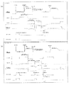
図1は本発明の実施形態であるシート後処理装置の全体の概略構成図であり、シート後処理装置1の内部には、搬送ガイド板201と、上方へ回動可能な開閉ガイド板202と、排紙ガイド板203が設けられており、各ガイド板201,202,203により搬送路204が形成されている。
FIG. 1 is a schematic configuration diagram of an entire sheet post-processing apparatus according to an embodiment of the present invention. Inside the
前記搬送路204におけるシート搬送方向上流の装置側部には、搬送ガイド板201と開閉ガイド板202との端部によって搬入口205が形成されており、この搬入口205の装置内部近傍にシート位置を検知する入口センサ206が設けられ、入口センサ206の近傍下流に搬送ローラ対207が設けられている。さらに、搬送路204の下流には排紙ローラ対208が設けられており、排紙ローラ対208の近傍上流に排紙センサ209が設けられている。
A
図2は本実施形態における前記搬送ローラ対と前記排紙ローラ対を示す斜視図であり、搬送ローラ対207の駆動側搬送ローラ207aと、排紙ローラ対208の駆動側排紙ローラ208aとは、プーリ210,タイミングベルト211を介してステッピングモータ212に連結されており、ステッピングモータ212の回転により各ローラ対207,208が回転駆動される。
FIG. 2 is a perspective view showing the transport roller pair and the paper discharge roller pair in this embodiment. The drive
図3は本実施形態における排紙ローラ対の構成を示す斜視図であって、(a)は正面側を示し、(b)は背面側を示す。 3A and 3B are perspective views showing the configuration of the paper discharge roller pair in the present embodiment. FIG. 3A shows the front side, and FIG. 3B shows the rear side.
図3において、排紙ローラ対208の駆動側排紙ローラ208aにおけるローラ軸には、揺動アーム213が回転可能に設けられており、揺動アーム213には弾性摩擦部材(例えばスポンジ製)からなる移送部材としての叩きコロ214が設けられている。この叩きコロ214は、タイミングベルト215,プーリ216,軸217,プーリ218,タイミングベルト219を介して、駆動側排紙ローラ208aのローラ軸に固定されたプーリ220に連結されており、駆動側排紙ローラ208aの回転により、叩きコロ214が同一方向に回転する構成になっている。
In FIG. 3, a
前記揺動アーム213は、自体の重み、あるいはスプリング(図示せず)によって、図1に示すように、常時、シート整合トレイであるスティプルトレイ401方向に荷重を受けた状態にあり、さらに、逆方向に荷重を負荷されたレバー221によってストッパ部(図示せず)に突き当てられた位置にて保持されている。レバー221の往復回動により揺動アーム213がスティプルトレイ401方向に回動して、叩きコロ214がスティプルトレイ401に当接し、さらに回動して、再びストッパ部に突き当てられて停止する構成になっている。
The
図4,図5は本実施形態における前記レバーの駆動部の構成例を示す斜視図である。 4 and 5 are perspective views showing a configuration example of the drive portion of the lever in the present embodiment.
図4に示す構成例では、レバー221の往復回動が、レバー221に連結された直流ソレノイド装置であるDC/SOL223によって駆動される構成になっている。
In the configuration example shown in FIG. 4, the reciprocating rotation of the
また、図5に示す構成例では、ステッピングモータ224の回転駆動を受けて、タイミングベルト225を介して連結されたカム226が回転し、レバー221から延出する長レバー221aのリンク部227に挿入されたカム突起部226aの回転により駆動される構成になっている。
Further, in the configuration example shown in FIG. 5, the
図6は本実施形態における駆動側排紙ローラを示す斜視図であり、排紙ローラ対208の駆動側ローラ208aのローラ軸にはギヤ228が嵌合されており、さらに駆動側ローラ208aのローラ軸にはホルダ229が回転可能に設けられ、このホルダ229に弾性摩擦部材(例えばスポンジ製)からなる戻しコロ230が設けられて、中間ギヤ231を介して前記ギヤ228に連結されている。この構成により、戻しコロ230に対して駆動側排紙ローラ208aの回転が伝達される。またホルダ229は、自体の重みと戻しコロ230の重みによって、常時、前記スティプルトレイ401方向に荷重が負荷されており、戻しコロ230の外周は、スティプルトレイ401に常時接触した状態にて回転する。
FIG. 6 is a perspective view showing the drive-side discharge roller in this embodiment. A
次に、本実施形態におけるシート整合部の構成を説明する。 Next, the configuration of the sheet alignment unit in the present embodiment will be described.
図7は本実施形態におけるシート整合トレイであるスティプルトレイの関連構造を示す斜視図であり、スティプルトレイ401の両側部には、シートの側端部を押圧してシート側面を整合する側端フェンスであるジョガーフェンス402,403が設けられており、ジョガーフェンス402,403は、スティプルトレイ401に固定されたガイド軸(図示せず)に挿入されて移動ガイドされ、タイミングベルト(図示せず)を介してステッピングモータ406,407に連結されて、ステッピングモータ406,407の正逆回転駆動により直線往復移動を行う。また、スティプルトレイ401には、ジョガーフェンス402,403の待機位置を検出するホームセンサ408,409が設けられている。
FIG. 7 is a perspective view showing a related structure of a staple tray that is a sheet alignment tray in the present embodiment. The side of the
さらに、スティプルトレイ401のシート搬送方向上流側には、シートの搬送方向端部に当接してシートの搬送方向の整合を行う後端フェンスである基準フェンス410,411が設けられている。また、基準フェンス410,411間には、後で詳述するシート放出部材としての鉤状のレバー体である放出爪430が設置されている。
Further, on the upstream side in the sheet conveyance direction of the
次に、前記構成の本実施形態におけるシート搬入から整合までの各部動作を説明する。 Next, each part operation | movement from sheet carrying in to alignment in this embodiment of the said structure is demonstrated.
図8は本実施形態のシート後処理装置における各部の具体的な動作タイミングを示すタイミングチャートであり、(a)はソートモード、(b)はスティプルモードの動作タイミングを示している。 FIG. 8 is a timing chart showing specific operation timings of each part in the sheet post-processing apparatus of the present embodiment, where (a) shows the operation timing in the sort mode and (b) shows the operation timing in the stipple mode.
ソートモード時とスティプルモード時とにおいて基本的な動作タイミングは同じであり、図8を参照して要部の動作について説明する。これらの動作タイミングの制御は装置本体に設けられたCPUなどからなる図示しない制御手段にてコントロールされる。 The basic operation timing is the same between the sort mode and the stipple mode, and the operation of the main part will be described with reference to FIG. Control of these operation timings is controlled by a control means (not shown) including a CPU or the like provided in the apparatus main body.
画像形成装置などから排出されたシートは、シートの搬送方向長さが小サイズの場合(例えば、B5Y/A4Y)、搬入口205に進入し、入口センサ206がシート先端を検出してから一定量搬送後(20mm搬送後)、ステッピングモータ212が加速し、シートを受入れ線速(138mm/s)から500mm/sに加速させ搬送する。また、シートの搬送方向長さが大サイズ(上記以外のサイズ)の場合は、シート後端が画像形成装置側の排紙センサ(図示せず)を通過してから一定量搬送後、加速搬送する。
When the length of the sheet discharged in the image forming apparatus or the like is small (for example, B5Y / A4Y), the sheet enters the carry-in
搬送路204内を加速搬送されたシートは、シート後端が入口センサ206を通過してから一定量搬送後(シート後端が排紙ローラ対208の上流30mmに達した位置)、ステッピングモータ212の減速によりシートを減速搬送させ、小サイズの場合には200mm/sに、大サイズの場合には300mm/sに減速し、シートは、前記線速にて排紙ローラ対208によってスティプルトレイ401上に排出される。
The sheet that is accelerated and conveyed in the conveyance path 204 is conveyed by a certain amount after the sheet trailing edge passes through the inlet sensor 206 (position where the sheet trailing edge reaches 30 mm upstream of the discharge roller pair 208), and then the stepping
シート後端が入口センサ206を通過して一定量搬送して、排紙ローラ対208を抜けた後(シート後端が排紙ローラ対208を通過して約5mm搬送後)、DC/SOL223、あるいはステッピングモータ224の駆動によりレバー221が回動開始し、揺動アーム213がスティプルトレイ401方向に回動して、叩きコロ214がスティプルトレイ401上に排出されたシート後端付近に当接し、叩きコロ214の回転によりシート後端を基準フェンス410,411に当接させるべく搬送する。また、叩きコロ214により基準フェンス410,411に後端を当接されたシートは、戻しコロ230の回転によって、更に基準フェンス方向410,411方向に搬送され、姿勢が保持される。
After the sheet trailing edge passes through the
図9,図10は本実施形態における前記ジョガーフェンスのシート整合動作を示す説明図であり、図9はソートモード時の整合動作を示し、図10はスティプルモード時の整合動作を示している。 9 and 10 are explanatory diagrams showing the sheet alignment operation of the jogger fence in the present embodiment, FIG. 9 shows the alignment operation in the sort mode, and FIG. 10 shows the alignment operation in the stipple mode. .
画像形成装置などからのシート排紙信号を受けると同時に、ジョガーフェンス402,403は、搬入されるシート幅方向サイズにより受入れ位置に移動する。このときのジョガーフェンス402,403の移動は、図9に示すシフトモードの場合はシート幅+15mm、図10に示すスティプルモード時の場合はシート幅+7mmの位置まで移動し停止して受入れ位置とする。
At the same time as receiving a sheet discharge signal from the image forming apparatus or the like, the
さらに、図9に示すシフトモード時の場合の動作について概略説明すると、(a)〜(d)に示すように、シート後端が排紙ローラ対208を通過し、叩きコロ214および戻しコロ230によって基準フェンス410,411に当接した後、寄せ側としての一方のジョガーフェンス402が30mm、基準側としてのジョガーフェンス403方向に移動し、シート側端を基準側のジョガーフェンス403に当接させて整合し、再び30mm後退して、受入れ位置にて停止して次シートの排出を待ち、順次、排出シートに対して同様の動作を繰り返し、シート束を基準側のジョガーフェンス403に整合する。
Further, the operation in the shift mode shown in FIG. 9 will be briefly described. As shown in FIGS. 9A to 9D, the trailing edge of the sheet passes through the sheet
また、所定枚数のシートを整合し、放出爪430の動作によりシート束を排紙トレイ301に放出(e)した後、次のシートはジョガーフェンス402,403の寄せ側と基準側とが入れ替わり動作を行うことにより、直前部のシート束と逆方向に寄せ動作を行う((f)〜(h))。これを所定の部数繰り返すことにより、シート束を排紙トレイ301上にシフト積載する。所定の部数の処理が終了した後、ホームポジションに戻って待機する(i)。
Further, after aligning a predetermined number of sheets and discharging (e) the sheet bundle to the
また、ジョガーフェンス402,403の動作タイミングは全て、入口センサ206のシート後端通過検出に基づき、前記制御手段の時間管理により制御されている。
In addition, the operation timings of the
図10に示すスティプルモード時の場合の動作について説明すると、(a)〜(c)に示すように、シート後端が排紙ローラ対208を通過し、叩きコロ214が回動開始すると同時に、ジョガーフェンス402,403が5mm前進して、シート幅+2mmの位置にて停止する。更にシート後端が基準フェンス410,411に当接すると同時に2.5mm前進し(d)、シートを中央に整合し、再び受入れ位置に後退して停止し、次のシートの排出を待ち(e)、順次、排出シートに対して前記動作を繰り返し、シート束を中央に整合する。
The operation in the stipple mode shown in FIG. 10 will be described. As shown in FIGS. 10A to 10C, the trailing edge of the sheet passes through the
所定枚数の整合動作が終了すると(f)、スティプル手段であるスティプラ420によってシート束の後端付近所定位置に綴じ処理が施され(g)、鉤状のレバー体である放出爪430によって排紙トレイ301上に放出される(h)。所定の部数の処理が終了した後、ホームポジションに戻って待機する(j)。
When the predetermined number of alignment operations are completed (f), the
また、ジョガーフェンス402,403の動作タイミングは全て、前記と同様に入口センサ206のシート後端通過検出からの時間管理により制御手段により制御されている。
Further, the operation timings of the
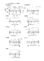
図11(a)〜(c)は本実施形態における基準フェンス部分の構成およびその動作を示す説明図である。 FIGS. 11A to 11C are explanatory views showing the configuration and operation of the reference fence portion in the present embodiment.
基準フェンス410,411は、スライドガイド部410a,411aに挿入されたガイド軸412に沿って、シート幅方向に移動可能に取り付けられており、一方の基準フェンス410は引張りスプリング413によってスティプルトレイ401の中央方向に常時力が加えられている。また、基準フェンス410,411には、ラック部410b,411bが一体に設けられており、ピニオンギヤ414を介してそれぞれ連結されている。
The
図11(b)に示すように、スティプル駆動モータ421の駆動により、スティプラ420がシート幅方向に沿って中央方向(図中左方向)に移動する際に、スティプラ420の突起部420aにて引っ掛けられている一方の基準フェンス411が、引張りスプリング413の力により共に移動し、ラック部410b,ピニオンギヤ414,ラック部411bを介して、基準フェンス410も中央方向(図中右方向)移動する。
As shown in FIG. 11B, when the
さらに、図11(c)に示すように、スティプラ420が移動して突出部420aが基準フェンス410を引っ掛けて移動(図中左方向)を続けると、基準フェンス410はラック部410b,411b、およびピニオンギヤ414によって両端方向(図中右方向)に移動する。
Furthermore, as shown in FIG. 11 (c), when the
これによって、スティプラ420にて各サイズシートの所望の位置に綴じ処理を行う際に、基準フェンス410,411の位置は、シート幅方向中央に対して常に対称に位置することになる。
Accordingly, when the
図12,図13は本実施形態における基準フェンス部分の構成の変形例を示す説明図である。図12に示す変形例において、前記ラック部410b,411b、およびピニオンギヤ414の代わりに、駆動手段としてタイミングベルト417およびプーリ416を設け、前記と同様の動作を行うようにしている。
12 and 13 are explanatory views showing a modification of the configuration of the reference fence portion in the present embodiment. In the modification shown in FIG. 12, a
図13に示す変形例においては、ラック部410b,411b、およびピニオンギヤ414の代わりに、ワイヤ415とプーリ418とを設けており、ワイヤ415の両端に固定された基準フェンス410,411が前記と同様の動作を行うようにしている。
In the modification shown in FIG. 13, instead of the
次に、排紙トレイ部の構成を説明する。 Next, the configuration of the paper discharge tray unit will be described.
図14〜図16は本実施形態における排紙トレイ部分の構成を示す斜視図であり、排紙トレイ301は、支持部材302,303に固定されており、支持部材302,303はタイミングベルト304,305とプーリ307を介して駆動軸306に連結されている。さらに駆動軸306にはギヤ308が嵌合されており、ギヤ308を介してDCモータ309に連結されている。このDCモータ309の回転により、排紙トレイ301の昇降動作が行われる。排紙トレイ301の端部にはエンドフェンス310が略垂直に設けられている。
14 to 16 are perspective views showing the configuration of the paper discharge tray portion in this embodiment. The
図15,図16に示すように、エンドフェンス310にはレバー313が嵌合された回転軸312を回転可能に取り付けており、回転軸312の両端付近にはシート押え部材311が2個回転可能に挿入されている。また、シート押え部材311には、先端部をエンドフェンス310方向に加圧させるスプリング(図示せず)が設けられている。さらに、回転軸312の一端付近にはDC/SOL315が固定されており、このDC/SOL315の動作により回転軸312が一定角度の往復回転動作をし、これによりレバー313が回動してシート押え部材311を回動させる。また、エンドフェンス310には、シート高さ検知センサ314が設けられている。
As shown in FIGS. 15 and 16, a
シート押え部材311は、通常、前記加圧スプリングによって先端押圧部311aがエンドフェンス310のシート整合面より突出した位置に停止しており、DC/SOL315の吸引動作により、先端押圧部311aがエンドフェンス310のシート整合面より完全に埋没する位置まで回動する。
The
排紙トレイ301の積載シート高さ検出は、排紙トレイ301の上昇により積載されたシート上面が、エンドフェンス310より突出したシート押え部材311の先端押圧部311aを押し上げることにより、シート押圧部材311の一部に設けられた検出部をシート高さ検知センサ314が検出することにより行う。
The detection of the stacked sheet height of the
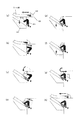
図17,図18は本実施形態におけるシート排出時の前記排紙トレイ部分の動作例の説明図である。図17,図18および図13〜図15を参照して排紙トレイ部分の動作を説明する。 17 and 18 are explanatory diagrams of an operation example of the paper discharge tray portion at the time of sheet discharge in the present embodiment. The operation of the paper discharge tray will be described with reference to FIGS. 17 and 18 and FIGS.
図17,図18に示す構成例共に、排紙ローラ対208によってシート整合部にシートが排出される際の排紙トレイ301の待機位置は、排紙トレイ301がシート押え部材311の先端押圧部311aを押し上げてシート高さ検知センサ314が検出した位置、あるいは、その位置より所定の高さ上昇させた位置であり、この位置にてシート束の整合動作およびスティプル動作を行う。
In both the configuration examples shown in FIGS. 17 and 18, when the sheet is discharged to the sheet aligning portion by the
図17(a),図18(b)に示すように、ジョガーフェンス402,403によって整合され、ソート処理およびスティプル処理されたシート束は、放出爪430が前進することによって排紙トレイ301に放出される。
As shown in FIGS. 17A and 18B, the sheet bundle aligned by the
放出爪430が前進し、スティプルトレイ401の下流端より所定の距離手前にて停止すると同時に、図17に示す例では、DC/SOL315が吸引し、シート押え部材311がエンドフェンス310より完全に埋没する位置まで回動する(b)。
In the example shown in FIG. 17, the DC /
また、放出爪430が前進開始すると同時に、DCモータ309が駆動開始し排紙トレイ301を所定の距離下降させる。放出爪430が再び前進し、シート束後端を排紙トレイ301上に放出した位置にて停止した直後、DC/SOL315がOFFしてシート押え部材311が突出し、排紙トレイ301上に放出されたシート束後端部を押さえる((c),(d))。シート押え部材311がシート束後端部を押さえた後に、放出爪430が再び前進して、ホーム位置に戻り停止する((e)〜(g))。
At the same time as the
シート押え部材311がシート束後端部を押さえたとき、シート高さ検知センサ314が検知していない状態の場合、排紙トレイ301が、シート検知センサ314の検知高さまで下降し、検知位置にて再び上昇して整合位置に停止し、次のシート束の整合に備える(h)。
When the
図18に示す例では、放出爪301が前進し停止すると同時に(b)、DCモータ309が駆動開始し排紙トレイ301を所定の距離下降し(c)、シート束を排紙トレイ301上に落下積載させ、排紙トレイ301の所定量下降後停止と同時に、DC/SOL315が吸引し、シート押さえ部材311がエンドフェンス310より完全に埋没する位置まで回動し(d)、直後にDC/SOL315がOFFし、シート押え部材311が、再びエンドフェンス310から突出し((e),(f))、再び排紙トレイ301が再上昇して、排紙トレイ301上に積載されたシート束上面がシート押え部材311を押し上げ、シート高さ検知センサ314が検出する位置にて停止し(g)、あるいは検出してから所定の高さ上昇後に停止し、シート束後端付近をシート押え部材311の先端押圧部311aにて押さえ、次のシート排出に備える(h)。
In the example shown in FIG. 18, at the same time as the
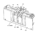
図19〜図21は本実施形態におけるスティプルトレイの構成を示す斜視図であり、スティプルトレイ401の下流端の中央部は、その両脇に対して5mm突出した突出部441が設けられており、さらに、複数(本例では2本)の放出爪430の間には、突出部441に対して突出量を0mm〜6mm変化可能に出没可能な構成の凸部443が設けられている。シート整合トレイのシート搬送方向下流端部の中央部分に、そのシート搬送方向下流端部よりもシート積載トレイ方向に出没可能に突出する凸部が設けられ、しかもシート整合トレイのシート搬送方向下流端部の中央部分に、そのシート搬送方向下流端部よりも前記シート積載トレイ方向に突出した突出部が設けられていて、前述の凸部は、突出部よりもさらにシート積載トレイ方向に突出可能となっているのである。
19 to 21 are perspective views showing the configuration of the staple tray in the present embodiment, and the central portion of the downstream end of the
突出部441は、エンドフェンス310におけるシート後端整合面321上部の曲面321aと連続した曲面を有し、その両側に対して突出していることにより、放出爪430によってシート束が排紙トレイ301上に放出される際にスキューが発生した場合において、シート束後端の両端部がスティプルトレイ401の下流端に残り、落下不良となることを防止し、確実に排紙トレイ301上に落下させることができる。このように、本例のシート処理装置においては、シート整合トレイにおけるシート搬送方向下流端部の中央部分に、該シート整合トレイにおけるシート搬送方向下流端部の両側部分よりもシート積載トレイ方向に突出する突出部が設けられており、この構成によって、放出爪によるシート束の放出動作時にシート束にスキューが生じた場合においても、シート束の両端付近がシート整合トレイにおけるシート搬送方向下流端に引っ掛ることなく、確実にシート積載トレイ上に放出させることができる。
The protruding
また、凸部443が突出部441に対して、手動などにて出没可能に突出させることが可能な構成にすることにより、凸部443を突出させ、シート束後端の排紙トレイ301への落下位置を変化させることが可能となり、シート束後端部の状態により変化する排紙トレイ301上への落下位置を調整することができる。これによりシート束後端部の状態による放出不具合(シート束後端部がエンドフェンス整合面321aに引っ掛かり放出爪によって挟み込まれる不具合)を防止することが可能となる。このように、本例のシート処理装置においては、シート整合トレイの突出部に、放出爪の回動両側付近においてシート積載トレイ上のシート後端部を整合させるフェンス部の整合面に対して突出する凸部が設けられており、この構成によって、シート後端付近が上向きにカールしたシート束をシート積載トレイ上に放出する際、シート束の後端部がフェンス部の整合面に引っ掛ることなく、確実にシート積載トレイ上に放出させることができる。しかも、シート整合トレイにおけるシート搬送方向下流の凸部が、シート整合トレイに対して出没可能に設けられており、この構成によって、処理するシート束の状態によってシート束の後端部のシート積載トレイ上への放出位置を変化させることが可能になり、シート束の状態によらず確実にシート積載トレイ上に放出させることができる。
また、本例のシート処理装置においては、図19及び図21から明らかなように、凸部は1つ設けられ、突出部は2つ設けられていて、これらの突出部は、シート束の幅方向に互いに離間して配置され、両突出部の間に1つの凸部が配置され、放出爪は2つ設けられていて、2つの突出部のうちの一方の突出部と凸部との間を2つの放出爪のうちの一方の放出爪が通り、他方の突出部と凸部との間に他方の放出爪が通るように、2つの突出部と1つの凸部が配置されている。
Further, by adopting a configuration in which the
Further, in the sheet processing apparatus of this example, as is apparent from FIGS. 19 and 21, one protrusion is provided and two protrusions are provided, and these protrusions are the width of the sheet bundle. The projections are arranged apart from each other in the direction, one projection is arranged between the two projections, two discharge claws are provided, and between one projection and the projection of the two projections The two protrusions and one protrusion are arranged so that one of the two discharge claws passes through and the other discharge nail passes between the other protrusion and the protrusion.
本発明は、複写機,プリンタなどの画像形成装置などから排紙されるシートに対して各種後処理を行うためのシート処理装置に適用される。 The present invention is applied to a sheet processing apparatus for performing various post-processing on a sheet discharged from an image forming apparatus such as a copying machine or a printer.
1 シート後処理装置
204 搬送路
208 排紙ローラ対
214 叩きコロ
230 戻しコロ
301 排紙トレイ
310 エンドフェンス
311 シート押え部材
311a 先端押圧部
401 スティプルトレイ
402,403 ジョガーフェンス
410,411 基準フェンス
420 スティプラ
430 放出爪
441 突出部
443 凸部
230 戻しコロ
DESCRIPTION OF
Claims (5)
前記シート放出部材を、前記シート束の後端部を押圧して前記シート積載トレイへ押出し、かつ該シート束の後端部を前記シート積載トレイ上に落下させるようにする回動可能な鉤状の放出爪にて構成し、前記シート整合トレイのシート搬送方向下流端部の中央部分に、該シート搬送方向下流端部よりも前記シート積載トレイ方向に出没可能に突出する凸部を設けたことを特徴とするシート処理装置。 A sheet alignment tray that receives and stacks the sheets, a transfer member that moves the sheets stacked on the sheet alignment tray one by one, and an end of the sheet that is conveyed by the transfer member in the conveying direction. A rear end fence that performs alignment in the conveying direction, a side end fence that aligns the side surfaces of the sheets aligned by pressing the side end portions of the sheets aligned by the rear end fence, and the aligned sheet bundle to press the sheet In a sheet processing apparatus comprising a sheet discharge member that is transferred onto a sheet stacking tray provided downstream in the sheet conveying direction of the alignment tray,
A rotatable bowl-like shape that pushes the rear end portion of the sheet bundle to push the sheet discharge member onto the sheet stacking tray and drops the rear end portion of the sheet bundle onto the sheet stacking tray. constituted by a discharge claw, the central portion of the sheet conveyance direction downstream end of the sheet align tray that was provided a convex portion than the sheet conveying direction downstream end projecting retractably to said sheet stacking tray direction A sheet processing apparatus.
Priority Applications (1)
| Application Number | Priority Date | Filing Date | Title |
|---|---|---|---|
| JP2007239048A JP4976246B2 (en) | 2007-09-14 | 2007-09-14 | Sheet processing device |
Applications Claiming Priority (1)
| Application Number | Priority Date | Filing Date | Title |
|---|---|---|---|
| JP2007239048A JP4976246B2 (en) | 2007-09-14 | 2007-09-14 | Sheet processing device |
Publications (2)
| Publication Number | Publication Date |
|---|---|
| JP2009067557A JP2009067557A (en) | 2009-04-02 |
| JP4976246B2 true JP4976246B2 (en) | 2012-07-18 |
Family
ID=40604236
Family Applications (1)
| Application Number | Title | Priority Date | Filing Date |
|---|---|---|---|
| JP2007239048A Expired - Fee Related JP4976246B2 (en) | 2007-09-14 | 2007-09-14 | Sheet processing device |
Country Status (1)
| Country | Link |
|---|---|
| JP (1) | JP4976246B2 (en) |
Families Citing this family (3)
| Publication number | Priority date | Publication date | Assignee | Title |
|---|---|---|---|---|
| JP5838724B2 (en) * | 2011-10-27 | 2016-01-06 | 富士ゼロックス株式会社 | Post-processing apparatus and image forming apparatus |
| JP6145794B2 (en) * | 2014-09-19 | 2017-06-14 | コニカミノルタ株式会社 | Post-processing apparatus and image forming system |
| KR20210136366A (en) * | 2020-05-07 | 2021-11-17 | 휴렛-팩커드 디벨롭먼트 컴퍼니, 엘.피. | Paper pressing structure operated in conjunction with paper discharging operation of ejector |
Family Cites Families (4)
| Publication number | Priority date | Publication date | Assignee | Title |
|---|---|---|---|---|
| JP3995873B2 (en) * | 2000-08-29 | 2007-10-24 | シャープ株式会社 | Sheet discharging apparatus and sheet post-processing apparatus using the same |
| JP2003128332A (en) * | 2001-10-25 | 2003-05-08 | Sharp Corp | Sheet post-processing equipment |
| JP2005132610A (en) * | 2003-10-31 | 2005-05-26 | Canon Finetech Inc | Sheet handling device and image forming device having the same |
| JP2007076894A (en) * | 2005-09-16 | 2007-03-29 | Toshiba Tec Corp | Sheet post-processing device |
-
2007
- 2007-09-14 JP JP2007239048A patent/JP4976246B2/en not_active Expired - Fee Related
Also Published As
| Publication number | Publication date |
|---|---|
| JP2009067557A (en) | 2009-04-02 |
Similar Documents
| Publication | Publication Date | Title |
|---|---|---|
| JP4088206B2 (en) | Paper folding device, paper processing device, and image forming system | |
| JP5065191B2 (en) | Paper processing device | |
| JP2000327208A (en) | Sheet processing equipment | |
| JP3655478B2 (en) | Paper post-processing apparatus and image forming apparatus | |
| US6886828B2 (en) | Sheet finishing apparatus and image forming apparatus equipped with the same | |
| JPH11165935A (en) | Output tray and paper post-processing device | |
| JP4976246B2 (en) | Sheet processing device | |
| JP4932675B2 (en) | Sheet processing apparatus and image forming apparatus | |
| US7173717B2 (en) | Sheet post-processing apparatus and image forming apparatus equipped with the same | |
| JP3832964B2 (en) | Paper post-processing apparatus and image forming apparatus | |
| US6951334B2 (en) | Sheet post-processing apparatus and image forming apparatus equipped with the same | |
| JP4355255B2 (en) | Paper processing apparatus and image forming apparatus | |
| JP4890417B2 (en) | Sheet member processing apparatus and image forming system apparatus | |
| JP4652089B2 (en) | Sheet processing device | |
| JP4687569B2 (en) | Sheet processing device | |
| JP3713393B2 (en) | Paper processing device | |
| JP5336316B2 (en) | Sheet stacking apparatus, post-processing apparatus including the same, and image forming system | |
| JP4500713B2 (en) | Sheet discharging apparatus and sheet post-processing apparatus using the same | |
| JPH06211414A (en) | Paper post-processing device | |
| JP3850759B2 (en) | Paper processing apparatus and image forming system | |
| JP5123719B2 (en) | Post-processing equipment | |
| JP2002020025A (en) | Paper handling equipment | |
| JP2001019252A (en) | Paper ejection device | |
| JP5117585B2 (en) | Paper processing apparatus and image forming system | |
| JP2004262625A (en) | Paper processing apparatus and image forming system |
Legal Events
| Date | Code | Title | Description |
|---|---|---|---|
| A621 | Written request for application examination |
Free format text: JAPANESE INTERMEDIATE CODE: A621 Effective date: 20100412 |
|
| RD02 | Notification of acceptance of power of attorney |
Free format text: JAPANESE INTERMEDIATE CODE: A7422 Effective date: 20100616 |
|
| RD04 | Notification of resignation of power of attorney |
Free format text: JAPANESE INTERMEDIATE CODE: A7424 Effective date: 20100624 |
|
| A977 | Report on retrieval |
Free format text: JAPANESE INTERMEDIATE CODE: A971007 Effective date: 20111012 |
|
| A131 | Notification of reasons for refusal |
Free format text: JAPANESE INTERMEDIATE CODE: A131 Effective date: 20111014 |
|
| TRDD | Decision of grant or rejection written | ||
| A01 | Written decision to grant a patent or to grant a registration (utility model) |
Free format text: JAPANESE INTERMEDIATE CODE: A01 Effective date: 20120409 |
|
| A01 | Written decision to grant a patent or to grant a registration (utility model) |
Free format text: JAPANESE INTERMEDIATE CODE: A01 |
|
| A61 | First payment of annual fees (during grant procedure) |
Free format text: JAPANESE INTERMEDIATE CODE: A61 Effective date: 20120412 |
|
| R150 | Certificate of patent or registration of utility model |
Ref document number: 4976246 Country of ref document: JP Free format text: JAPANESE INTERMEDIATE CODE: R150 Free format text: JAPANESE INTERMEDIATE CODE: R150 |
|
| FPAY | Renewal fee payment (event date is renewal date of database) |
Free format text: PAYMENT UNTIL: 20150420 Year of fee payment: 3 |
|
| LAPS | Cancellation because of no payment of annual fees |