JP4969737B2 - Method and apparatus for forming coating film on shaft surface - Google Patents
Method and apparatus for forming coating film on shaft surface Download PDFInfo
- Publication number
- JP4969737B2 JP4969737B2 JP2001172558A JP2001172558A JP4969737B2 JP 4969737 B2 JP4969737 B2 JP 4969737B2 JP 2001172558 A JP2001172558 A JP 2001172558A JP 2001172558 A JP2001172558 A JP 2001172558A JP 4969737 B2 JP4969737 B2 JP 4969737B2
- Authority
- JP
- Japan
- Prior art keywords
- coating
- shaft
- roller
- outer peripheral
- peripheral surface
- Prior art date
- Legal status (The legal status is an assumption and is not a legal conclusion. Google has not performed a legal analysis and makes no representation as to the accuracy of the status listed.)
- Expired - Lifetime
Links
- 239000011248 coating agent Substances 0.000 title claims description 172
- 238000000576 coating method Methods 0.000 title claims description 172
- 238000000034 method Methods 0.000 title claims description 11
- 239000000463 material Substances 0.000 claims description 76
- 230000002093 peripheral effect Effects 0.000 claims description 49
- 238000003860 storage Methods 0.000 claims description 16
- 238000001816 cooling Methods 0.000 claims description 11
- 239000000853 adhesive Substances 0.000 claims description 10
- 230000001070 adhesive effect Effects 0.000 claims description 10
- 238000010438 heat treatment Methods 0.000 claims description 5
- 238000012546 transfer Methods 0.000 description 10
- 229910052751 metal Inorganic materials 0.000 description 7
- 239000002184 metal Substances 0.000 description 7
- 238000002844 melting Methods 0.000 description 6
- 230000008018 melting Effects 0.000 description 6
- 239000006260 foam Substances 0.000 description 5
- 239000007788 liquid Substances 0.000 description 4
- 238000011144 upstream manufacturing Methods 0.000 description 3
- 239000004831 Hot glue Substances 0.000 description 2
- 239000003795 chemical substances by application Substances 0.000 description 2
- 238000007796 conventional method Methods 0.000 description 2
- 238000005096 rolling process Methods 0.000 description 2
- 238000000926 separation method Methods 0.000 description 2
- 229910000838 Al alloy Inorganic materials 0.000 description 1
- 238000009825 accumulation Methods 0.000 description 1
- 239000012790 adhesive layer Substances 0.000 description 1
- 238000013459 approach Methods 0.000 description 1
- DMFGNRRURHSENX-UHFFFAOYSA-N beryllium copper Chemical compound [Be].[Cu] DMFGNRRURHSENX-UHFFFAOYSA-N 0.000 description 1
- 230000015572 biosynthetic process Effects 0.000 description 1
- 230000000694 effects Effects 0.000 description 1
- PCHJSUWPFVWCPO-UHFFFAOYSA-N gold Chemical compound [Au] PCHJSUWPFVWCPO-UHFFFAOYSA-N 0.000 description 1
- 239000010931 gold Substances 0.000 description 1
- 229910052737 gold Inorganic materials 0.000 description 1
- 238000003780 insertion Methods 0.000 description 1
- 230000037431 insertion Effects 0.000 description 1
- 238000003754 machining Methods 0.000 description 1
- 238000004519 manufacturing process Methods 0.000 description 1
- 230000000630 rising effect Effects 0.000 description 1
Images


Landscapes
- Application Of Or Painting With Fluid Materials (AREA)
- Coating Apparatus (AREA)
Description
【0001】
【発明の属する技術分野】
本発明は、複写機等に使用される現像ローラ、帯電ローラ、給紙ローラ等のような、円筒形の弾性発泡体ローラの中央に貫挿される、いわゆる芯金等の軸の表面に、接着剤等の塗膜を均一に形成する方法及び装置に関する。
【0002】
【従来の技術】
上記の現像ローラや帯電ローラ等の製造工程においては、弾性発泡体に穿設した孔に、表面に熱溶融性の接着剤の塗膜を形成した芯金を挿入し、その後、上記接着剤を加熱して溶融させ、芯金と弾性発泡体とを互いに接着した後、冷却し、その後弾性発泡体の外形を、芯金を中心とした円筒状に機械加工して仕上げることがある。
【0003】
芯金の外周面に、熱溶融性の接着剤の塗膜を形成する従来の方法としては、例えば、ほぼ水平とした芯金をその中心軸線回りに回転させつつ、液状とした接着剤を芯金に向かって供給するノズルを、芯金の軸線と平行に移動させるようにしたものがある。
【0004】
【発明が解決しようとする課題】
しかし、上述のような従来の方法では、芯金の外周面に接着剤が螺旋状に付着されていくので、塗膜の表面に螺旋状の凹凸が生じ、その凹凸が、芯金を弾性発泡体の孔に挿入する際に、孔の縁に引っかかり、芯金の挿入が不円滑になったり、接着剤層に厚い部分と薄い部分とが生じ、芯金と弾性発泡体との接着が不均一となり、接着むらが生じる等の問題がある。
【0005】
本発明は、従来の技術が有する上記のような問題点に鑑み、軸の表面に、塗膜を、凹凸等が生じることなく、均一に、しかも簡単かつ迅速に形成することができるようにした軸表面への塗膜形成方法、及び装置を提供することを目的としている。
【0006】
【課題を解決するための手段】
本発明によると、上記課題は次のようにして解決される。
(1) 軸表面への塗膜形成方法において、ヒータにより加熱し、かつ一方向に定速回転させている塗布ローラの外周面に、熱溶融性の接着剤とした塗材を均一な厚さで供給するとともに、前記塗布ローラの外周面に、塗膜を形成しようとする予熱しておいた円柱状の軸を、その中心軸線回りに回転させつつ、前記塗布ローラと平行として、前記塗布ローラの外周面に供給された塗材の厚さより小さい距離だけ離れるように接近させ、前記軸が塗布ローラに接近後ほぼ360°以上回転した後、軸を塗布ローラの外周面から離す。
【0007】
(2) 上記(1)項において、塗膜が形成された軸を、塗布ローラから離した後、冷却する。
【0008】
(3) 上記(1)または(2)項において、塗膜が形成された軸を、塗布ローラから離すときの離脱速度を、塗布ローラの外周面の周速とほぼ同じかまたはそれより大とする。
【0009】
(4) 軸表面への塗膜形成装置において、モータにより一方向に定速回転させられるようにして、フレームに支持された塗布ローラと、この塗布ローラの外周面に、塗材を均一な厚さで供給する塗材供給手段と、塗膜を形成しようとする円柱状の軸を、モータにより中心軸線回りに回転させつつ、前記塗布ローラと平行として、前記塗布ローラの外周面に対して遠近移動可能として支持するワーク支持手段と、前記軸を、前記塗布ローラに対して、平行状態を保って、遠近移動させる移動手段とを備え、前記塗材供給手段は、溶融した塗材を収容する塗材収容槽と、塗布ローラの外周面に対する間隔を調節可能として前記塗材収容槽に取り付けられた膜厚調整ブレードとを備えているものとする。
【0010】
(5) 軸表面への塗膜形成装置において、モータにより一方向に定速回転させられるようにして、フレームに支持された塗布ローラと、この塗布ローラの外周面に、塗材を均一な厚さで供給する塗材供給手段と、塗膜を形成しようとする円柱状の軸を、モータにより中心軸線回りに回転させつつ、前記塗布ローラと平行として、前記塗布ローラの外周面に対して遠近移動可能として支持するワーク支持手段と、前記軸を、前記塗布ローラに対して、平行状態を保って、遠近移動させる移動手段とを備え、さらに、前記塗布ローラの外周面の近くに加熱用のヒータを設け、かつ塗膜を形成しようとする前記軸を予熱する予熱手段を設ける。
【0011】
(6) 上記(5)項において、予熱手段が、ヒータにより加熱されるようにした熱板と、塗膜を形成しようとする軸を、前記熱板上を転がるように移動させる送り手段とを備えるものとする。
【0012】
(7) 軸表面への塗膜形成装置において、モータにより一方向に定速回転させられるようにして、フレームに支持された塗布ローラと、この塗布ローラの外周面に、塗材を均一な厚さで供給する塗材供給手段と、塗膜を形成しようとする円柱状の軸を、モータにより中心軸線回りに回転させつつ、前記塗布ローラと平行として、前記塗布ローラの外周面に対して遠近移動可能として支持するワーク支持手段と、前記軸を、前記塗布ローラに対して、平行状態を保って、遠近移動させる移動手段とを備え、さらに、塗膜が形成された前記軸を支持し、低速で搬送する間に前記軸を自然冷却するコンベヤを有する冷却手段を設ける。
【0013】
【発明の実施の形態】
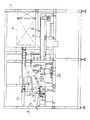
図1は、本発明の軸表面への塗膜形成装置の一実施形態を示す。
【0014】
この装置は、ほぼ直方体のフレーム(1)内のほぼ等高の位置に、表面に塗膜を形成しようとする多数の軸(2)(図2参照)を収容するホッパ(3)と、予熱装置(4)と、塗布装置(5)と、冷却装置(6)とが、左から右に向かって並ぶようにして配設され、予熱装置(4)の右端部から冷却装置(6)の左端部にかけての上方には、予熱された軸(2)を、予熱装置(4)から塗布装置(5)まで移送するのと同時に、塗布装置(5)において塗材が塗布された軸(2)を、冷却装置(6)まで移送する移送手段(7)が配設され、さらに冷却装置(6)の右部の上方には、塗材である熱溶融性の接着剤を、加熱溶融させて塗布装置(5)に供給するための塗材溶融タンク(8)が配設されている。
【0015】
図2に示すように、ホッパ(3)の底板(3a)は、右下方に向かって傾斜し、その右端と右方の側板(3b)との間には、ホッパ(3)内に収容された多数の軸(2)を、適時に油圧シリンダ(9)の作動により、上方に向かって突き上げることができるようにしたプッシャー(10)と、側板(3b)との間に、複数の軸(2)を縦方向に整列させて下方に向けて案内する出口ガイド(11)とが設けられている。
【0016】
出口ガイド(11)の直下には、その最下段の軸(2)の前後部を、前後1対のアーム(12)の先端部で受止めて、油圧シリンダ(13)の作動により、右方の予熱装置(4)に移送する送り装置(14)が設けられている。
【0017】
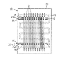
図1〜図4に示すように、予熱装置(4)は、送り装置(14)より1個ずつ送られてきた複数の軸(2)を、鋸歯状の複数の受け溝(15a)により、左右方向に等間隔をもって水平に支持する前後1対の支持板(15)と、各支持板(15)の外側に、油圧シリンダ(16)により昇降させられるようにして配設させられるとともに、上端に、支持板(15)の上端における受け溝(15a)と同一ピッチで、かつ半ピッチ分だけ左右にずらして設けられた鋸歯状の送りつめ(17)を有する前後1対の昇降板(18)と、左端の前後部より右方に向かって切り込まれた前後1対のスリット(20a)内に、前後の支持板(15)と昇降板(18)とが収容され、かつ前後の支持板(15)に支持された複数の軸(2)の下面に接するようにして、ほぼ水平に配設され、かつ内部に設けられたシーズヒータ等のヒータ(19)により、各軸(2)を均一に予熱するようにしたほぼ水平の熱板(20)とを備えている。
【0018】
油圧シリンダ(16)の作動により、昇降板(18)が昇降させられる毎に、送り装置(14)により送られてきた軸(2)、及び支持板(15)の各受け溝(15a)に受止された軸(2)は、傾斜する送りつめ(17)の縁と受け溝(15a)の縁とに沿って順次転がりつつ、受け溝(15a)の1ピッチ分だけ右方に送られる。
【0019】
すなわち、支持板(15)、油圧シリンダ(16)、昇降板(18)等により、複数の軸(2)を、熱板(20)上を順次右方に向けて歩進的に転がるように移動させる送り手段(21)が形成されている。
【0020】
熱板(20)は、例えば、ベリリウム銅製、または高強度アルミニウム合金製のものとするのが、強度、熱伝達、熱伝導等の点で好ましいが、その他の材料製のものとしてもよい。
【0021】
軸(2)の予熱温度は、100℃〜130℃とするのが好ましく、温度の局部的なばらつきは10℃以内に止めるのが好ましい。
【0022】
移送手段(7)は、フレーム(1)に水平に支持された左右方向を向くエアシリンダ(22)により、図1に示す左限と、同じく想像線で示す右限との範囲内を左右方向に移動させられるようにした下向きの短寸のエアシリンダ(23)と、その下端に設けられ、かつエアシリンダ(23)の作動により昇降させられるようにした水平の昇降板(24)と、昇降板(24)の左右両側部の前後に下向きに設けられ、かつ下端に設けた開閉式の1対のフィンガー(25)により、軸(2)の前後の端部を把持しうるようにした把持手段(26)とを備えている。
【0023】
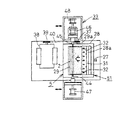
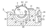
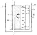
図1及び図5〜図8に示すように、塗布装置(5)は、フレーム(1)に固定され、かつ塗材溶融タンク(8)に塗材供給管(27)を介して接続された塗材収容槽(28)と、その前後の側壁に軸(29a)が回転自在に架設され、かつ下部が塗材収容槽(28)内に収容された溶融状態の塗材(30)に浸漬された前後方向を向く塗布ローラ(29)と、塗材収容槽(28)に設けられたブレード取付壁(28a)の上端に、塗布ローラ(29)に対する左右方向の取付位置を調節可能として取り付けられた膜厚調整ブレード(31)と、それと同様にしてブレード取付壁(28a)の上端両側部に、膜厚調整ブレード(31)と上下に重合するようにして取り付けられた塗布幅制限ブレード(32)(32)と、軸(2)を、回転させつつ、塗布ローラ(29)と平行かつ水平として、塗布ローラ(29)に対して遠近移動可能として支持するワーク支持手段(33)とを備えている。
【0024】
図7に示すように、塗材収容槽(28)には、その中に収容された塗材(30)の温度を検出する温度センサ(34)と、その温度センサ(34)の検出温度が予め設定した設定温度を維持するように、塗材(30)を加熱するヒータ(35)と、塗材収容槽(28)内の塗材(30)の液位を検出し、その液位が常に予め定めた範囲内に維持されるように、塗材溶融タンク(8)からの塗材(30)の供給量を調節するための液位センサ(36)とが設けられている。
【0025】
図6に示すように、塗材収容槽(28)の後端から突出する塗布ローラ(29)の軸(29a)の後端部には、スプロケット(37)が固嵌され、このスプロケット(37)と、塗材収容槽(28)の左側方に設置されたモータ(38)の軸に固嵌されたスプロケット(39)とには、チェーン(40)が掛け回され、塗布ローラ(29)は、モータ(38)の作動により、スプロケット(37)(39)とチェーン(40)を介して、図7における反時計回りに定速回転させられるようになっている。
【0026】
図5及び図6に示すように、ワーク支持手段(33)は、塗材収容槽(28)の下方に前後方向を向くようにして配設され、かつ横送り装置(41)により、左右方向に移動させられるようにしたスライドテーブル(42)と、その前後の端部より起立する支持台(43)(43)の上部に設けられ、軸(2)を、塗材収容槽(28)の上方において、塗布ローラ(29)と平行かつ水平の前後方向を向くようにして前後から挟む芯出し軸(44)と主軸(45)と、後部の支持台(43)に設けられ、主軸(45)を介して軸(2)を、図7における時計方向に回動させるモータ(46)とを備えている。
【0027】
芯出し軸(44)と主軸(45)とは、旋盤におけるのと同様のものでよく、主軸(45)側に、ワークである軸(2)を把持するチャック(図示略)を設け、またエアシリンダ(47)(48)の作動により、互いに内方に進退させられて、移送手段(7)における把持手段(26)により把持された軸(2)を、前後から挾圧把持したり、離脱したりしうるようになっている。
【0028】
横送り装置(41)は、スライドテーブル(42)の下面に設けた下向き突部(42a)に穿設したねじ孔(図示略)に螺合する左右方向を向くねじ杆(49)を、フレーム(1)に設けたモータ(50)により正逆回転させることによって、スライドテーブル(42)を左右方向に移動させることができるようになっている。
【0029】
塗布装置(5)においては、塗布ローラ(29)の外周面と膜厚調整ブレード(31)との間隙(D1)が適切な値となるように、膜厚調整ブレード(31)の位置を調整してブレード取付壁(28a)に固定するとともに、塗布幅制限ブレード(32)を、その先端が塗布ローラ(29)の外周面に常時摺接するようにして位置を調整した上で、ブレード取付壁(28a)に固定する。
【0030】
間隙(D1)は、塗材の材質、軸(2)の外周面に形成しようとする塗膜の厚さ等に基づいて定めるのがよいが、例えば、塗材(30)をEVA系の接着剤とした場合は、30〜500μmとするのがよい。
【0031】
この実施形態においては、塗材溶融タンク(8)、塗材供給管(27)、塗材収容槽(28)、膜厚調整ブレード(31)、塗布幅制限ブレード(32)等により、塗布ローラ(29)の外周面に、塗材を均一な厚さで供給する塗材供給手段(51)が形成されている。
【0032】
冷却装置(6)は、移送手段(7)における右方の把持手段(26)により把持されて送られてきた軸(2)の前後の端部を支持し、それを右方に向けて低速で搬送する間に、軸(2)を自然冷却するようにしたコンベヤ(52)を備えている。必要に応じて、コンベヤ(52)上に支持された多数の軸(2)に、冷却用の空気を供給する送風機(図示略)を設けてもよい。
【0033】
次に、上述の装置を用いた、本発明の軸表面への塗膜形成方法の一実施要領について説明する。
【0034】
上記装置の各部の駆動手段やヒータ等は、それらに接続された制御装置により、以下の説明のように作動するように、すべて自動的に制御されるようにするのが好ましい。
【0035】
ホッパ(3)内に収容された多数の軸(2)は、予め定めたサイクルタイム毎に、送り装置(14)により、1個ずつ予熱装置(4)に送られる。
【0036】
予熱装置(4)においては、送り装置(14)により送られてきた軸(2)は、送り手段(21)における昇降手段(24)の1回の昇降毎に、支持板(15)の受け溝(15a)に1ピッチずつ転がりつつ、歩進的に右方に送られ、その間に、ヒータ(19)により設定温度、例えば195℃に加熱された熱板(20)により、均一に加熱(予熱)される。
【0037】
予め定めた温度、例えば110℃までほぼ均一に加熱されて、支持板(15)の右端部に到達した軸(2)は、移送手段(7)における左方の把持手段(26)により前後の端部が把持されて、塗布装置(5)における所定の位置まで移送される。
【0038】
この位置で、軸(2)は、ワーク支持手段(33)における芯出し軸(44)と主軸(45)とにより前後から挾まれ、次いで移送手段(7)における把持手段(26)のフィンガー(25)が開いて、移送手段(7)は原位置に復帰させられる。
【0039】
軸(2)は、この後、モータ(46)の作動により、図7における時計回りに、例えば200〜400rpm の回転数で回転させられつつ、横送り装置(41)の作動により、塗布ローラ(29)に向かって、それと平行かつ水平状態を保って、例えば0.5m/sec の速度で右方へ移動させられる。
【0040】
一方、塗布ローラ(29)は、モータ(38)の作動により、図7における反時計方回りに、例えば20rpm の回転数で回転させられ、このとき、その下部が塗材(30)内に浸漬されているので、塗材(30)が外周面に付着し、その厚さは、膜厚調整ブレード(31)の通過時に、上述のように設定された間隙(D1)とほぼ同一厚さに調整され、余分な塗材(30)は膜厚調整ブレード(31)により掻き落される。また、塗布ローラ(29)の外周面の両側部に付着した塗材(30)は、塗布幅制限ブレード(32)によりすべてが掻き落され、塗布ローラ(29)の外周面に付着した塗材(30)の幅は、軸(2)の外周面における所望の塗材付着領域に制限される。
塗材(30)はEVA系の接着剤とし、塗材収容槽(28)の温度は140℃とする。
【0041】
この状態で、軸(2)が、塗布ローラ(29)の外周面に供給された塗材(30)の厚さより小さい予め定めた距離まで塗布ローラ(29)に接近すると、すなわち、軸(2)と塗布ローラ(29)との間隙(D2)が、間隙(D1)より小さい予め定めた値に到達すると、横送り装置(41)による軸(2)の右進が停止させられる。
【0042】
間隙(D2)は、塗材(30)をEVA系の接着剤とし、かつ間隙(D1)を上述のように30〜500μmとした場合、例えばD2=D1−(10〜200μm)とするのが好ましい。
【0043】
このとき、軸(2)の外周面には、塗布ローラ(29)の外周面に付着していた塗材(30)が、転写されるように移行して均一に付着する。
【0044】
このときの軸(2)の外周面の周速と、塗布ローラ(29)の外周面の周速とは、ほぼ一致させておくのが好ましい。それによって、軸(2)の外周面に付着する塗材(30)の厚さが所望のものより薄くなったり(軸(2)側が早い場合)、または塗布ローラ(29)の外周面における軸(2)の上流側に、塗材(30)のたまりが生じたり(軸(2)側が遅い場合)するのを防止することができるからである。
【0045】
軸(2)の右進が停止した時点から、軸(2)がほぼ360°以上回転したとき、横送り装置(41)が上述と逆方向に作動し、軸(2)は、塗布ローラ(29)から離れるように、左方に移動させられる。
【0046】
このときの軸(2)が塗布ローラ(29)から離脱するときの離脱速度は、塗布ローラ(29)の外周面の周速とほぼ同じかまたはそれより大きい値、例えば2m/sec に設定するのが好ましい。それより低速とすると、上述の軸(2)より上流側の塗材(30)のたまりが、軸(2)の外周面に移行し、軸(2)の外周面に、軸線方向を向く塗材(30)の盛り上がり部が形成され、軸(2)外周の塗材(30)の厚さが不均一になるからである。
【0047】
軸(2)が、移送手段(7)への受け渡し位置まで移動させられると、横送り装置(41)の作動が停止し、次いで、移送手段(7)における左方の把持手段(26)が予熱装置(4)における最右端の軸(2)を把持するのと同時に、右方の把持手段(26)により、ワーク支持手段(33)により支持されている塗装済みの軸(2)の前後の端部が把持され、ワーク支持手段(33)の芯出し軸(44)と主軸(45)とが前後に開いた後、塗装済みの軸(2)は、冷却装置(6)におけるコンベヤ(52)の左端部上に移載される。
【0048】
それと同時に、左方の把持手段(26)により把持された新たな軸(2)が、ワーク支持手段(33)に、上述したのと同様にして移載され、上述したのと同様の工程がくり返される。
【0049】
【発明の効果】
請求項1記載の発明によると、塗布ローラの外周面に付着した塗材が、軸の外周面に転写されるように移行することによって、軸の外周面に、塗膜を、凹凸等が生じることなく、均一に、しかも簡単かつ迅速に形成することができる。
【0050】
また、粘度の高い接着剤でも、軸表面に均一に塗ることができる。
【0051】
請求項2記載の発明によると、軸表面に付着した熱溶融性の接着剤を迅速に硬化させることができる。
【0052】
請求項3記載の発明によると、塗布ローラの外周面における軸より上流側に発生した塗材のたまりが、軸表面に移行して、軸表面に軸線方向を向く塗材の盛り上がり部が形成されるのを防止することができる。
【0053】
請求項4、5、および7記載の発明によると、請求項1記載の方法の発明を効果的に実施できるとともに、構造が簡単で安価な装置を提供することができる。
【0054】
請求項4記載の発明によると、塗布ローラの外周面に付着する塗材の厚さを自由に調節することができる。
【0055】
請求項5記載の発明によると、請求項1記載の方法の発明を効果的に実施できるとともに、軸表面に熱溶融性の塗材を均一に塗布することができる装置を提供することができる。
【0056】
請求項6記載の発明によると、塗膜を形成しようとする軸を、安価な手段により、連続的に、かつ均一に予熱することができる。
【0057】
請求項7記載の発明によると、請求項2記載の方法の発明を効果的に実施できる安価な装置を提供することができる。
【図面の簡単な説明】
【図1】 本発明の装置の一実施形態の一部を破断した正面図である。
【図2】 同じく、その装置におけるホッパと予熱装置との縦断正面図である。
【図3】 同じく、予熱装置の主要部を模式的に示す平面図である。
【図4】 同じく、予熱装置の主要部を模式的に示す正面図である。
【図5】 同じく、塗布装置の正面図である。
【図6】 同じく、塗布装置の平面図である。
【図7】 同じく、塗布装置の主要部を模式的に示す縦断正面図である。
【図8】 同じく、塗布装置の主要部を模式的に示す平面図である。
【符号の説明】
(1)フレーム
(2)軸
(3)ホッパ
(3a)底板
(3b)側板
(4)予熱装置
(5)塗布装置
(6)冷却装置
(7)移送手段
(8)塗材溶融タンク
(9)油圧シリンダ
(10)プッシャー
(11)出口ガイド
(12)アーム
(13)油圧シリンダ
(14)送り装置
(15)支持板
(15a)受け溝
(16)油圧シリンダ
(17)送りつめ
(18)昇降板
(19)ヒータ
(20)熱板
(20a)スリット
(21)送り手段
(22)エアシリンダ
(23)エアシリンダ
(24)昇降板
(25)フィンガー
(26)把持手段
(27)塗材供給管
(28)塗材収容槽
(28a)ブレード取付壁
(29)塗布ローラ
(29a)軸
(30)塗材
(31)膜厚調整ブレード
(32)塗布幅制限ブレード
(33)ワーク支持手段
(34)温度センサ
(35)ヒータ
(36)液位センサ
(37)スプロケット
(38)モータ
(39)スプロケット
(40)チェーン
(41)横送り装置
(42)スライドテーブル
(42a)下向き突部
(43)支持台
(44)芯出し軸
(45)主軸
(46)モータ
(47)(48)エアシリンダ
(49)ねじ杆
(50)モータ
(51)塗材供給手段
(52)コンベヤ
(D1)(D2)間隙[0001]
BACKGROUND OF THE INVENTION
The present invention adheres to the surface of a shaft, such as a so-called metal core, which is inserted into the center of a cylindrical elastic foam roller such as a developing roller, a charging roller, a paper feed roller, etc. used in a copying machine. The present invention relates to a method and an apparatus for uniformly forming a coating film such as an agent.
[0002]
[Prior art]
In the manufacturing process of the developing roller, the charging roller and the like, a cored bar having a heat-meltable adhesive coating formed on the surface is inserted into the hole formed in the elastic foam, and then the adhesive is removed. After heating and melting, the cored bar and the elastic foam are bonded to each other, cooled, and then the outer shape of the elastic foam is finished by machining into a cylindrical shape centering on the cored bar.
[0003]
As a conventional method for forming a coating film of a heat-meltable adhesive on the outer peripheral surface of a core metal, for example, a liquid adhesive is cored while rotating a substantially horizontal core metal around its central axis. There is a nozzle that moves toward the gold and moves in parallel with the axis of the core.
[0004]
[Problems to be solved by the invention]
However, in the conventional method as described above, since the adhesive is spirally attached to the outer peripheral surface of the core metal, spiral irregularities are formed on the surface of the coating film, and the irregularities cause the core metal to be elastically foamed. When inserted into a hole in the body, it is caught by the edge of the hole, and the insertion of the core metal becomes unsmooth, or a thick part and a thin part occur in the adhesive layer, and the adhesion between the core metal and the elastic foam is not good. There are problems such as uniformity and uneven adhesion.
[0005]
The present invention has been made in view of the above-mentioned problems of the prior art, and allows the coating film to be uniformly and easily and rapidly formed on the shaft surface without causing irregularities. It aims at providing the coating-film formation method and apparatus to the shaft surface.
[0006]
[Means for Solving the Problems]
According to the present invention, the above problem is solved as follows.
(1) In the method of forming a coating film to the shaft surface, heated by the heater, and the outer circumferential surface of the application roller that is constant speed in one direction, a uniform coating material in which a heat-fusible adhesive thickness The coating roller is rotated in parallel with the coating roller while rotating a pre-heated cylindrical shaft around the central axis of the coating roller on the outer peripheral surface of the coating roller. The outer peripheral surface of the coating roller is moved away from the coating material by a distance smaller than the thickness of the coating material, and after the shaft has rotated approximately 360 ° or more after approaching the coating roller, the shaft is separated from the outer circumferential surface of the coating roller.
[0007]
(2) In the above item (1) , the shaft on which the coating film is formed is separated from the coating roller and then cooled.
[0008]
(3) In the above item (1) or (2), the separation speed when the shaft on which the coating film is formed is separated from the coating roller is substantially equal to or greater than the circumferential speed of the outer circumferential surface of the coating roller. To do.
[0009]
(4) In the coating film forming apparatus on the shaft surface, a uniform thickness is applied to the coating roller supported by the frame so that it can be rotated at a constant speed in one direction by a motor and to the outer peripheral surface of the coating roller. The coating material supply means and the columnar shaft on which the coating film is to be formed are rotated around the central axis by a motor and parallel to the application roller, with respect to the outer peripheral surface of the application roller. A workpiece supporting means for supporting the movable body ; and a moving means for moving the shaft in a distance direction while maintaining a parallel state with respect to the application roller. The coating material supply means accommodates the molten coating material. It is assumed that a coating material storage tank and a film thickness adjusting blade attached to the coating material storage tank so as to be adjustable with respect to the outer peripheral surface of the coating roller are provided .
[0010]
(5) In the coating film forming apparatus on the shaft surface, a uniform thickness is applied to the coating roller supported by the frame so as to be rotated at a constant speed in one direction by a motor and to the outer peripheral surface of the coating roller. The coating material supply means and the columnar shaft on which the coating film is to be formed are rotated around the central axis by a motor and parallel to the application roller, with respect to the outer peripheral surface of the application roller. A work supporting means for supporting the movement; and a moving means for moving the shaft in a distance direction while maintaining a parallel state with respect to the application roller; and for heating near the outer peripheral surface of the application roller. the heater is provided, and provided with a preheating means for preheating the shaft to be provided with the coating film.
[0011]
(6) In the above paragraph (5) , the preheating means includes a hot plate that is heated by a heater, and a feed means that moves the shaft on which the coating film is to be formed to roll on the hot plate. Shall be provided.
[0012]
(7) In the coating film forming apparatus on the shaft surface, a uniform thickness is applied to the coating roller supported by the frame so as to be rotated at a constant speed in one direction by a motor and to the outer peripheral surface of the coating roller. The coating material supply means and the columnar shaft on which the coating film is to be formed are rotated around the central axis by a motor and parallel to the application roller, with respect to the outer peripheral surface of the application roller. a workpiece support means for supporting a movable, the shaft, relative to the application roller, while maintaining the parallel state, and a moving means for perspective move, further supporting the shaft coating film is formed, a cooling means having a conveyor for naturally cooling the shaft during the transport at low speed.
[0013]
DETAILED DESCRIPTION OF THE INVENTION
FIG. 1 shows an embodiment of a coating film forming apparatus for a shaft surface of the present invention.
[0014]
This apparatus includes a hopper (3) for accommodating a plurality of shafts (2) (see FIG. 2) for forming a coating film on a surface at a substantially equal height in a substantially rectangular parallelepiped frame (1), and a preheating. The device (4), the coating device (5), and the cooling device (6) are arranged so as to be arranged from left to right, and the cooling device (6) is arranged from the right end of the preheating device (4). Above the left end, the preheated shaft (2) is transferred from the preheating device (4) to the coating device (5), and at the same time, the shaft (2) on which the coating material is applied in the coating device (5). ) Is transferred to the cooling device (6), and a hot-melt adhesive as a coating material is heated and melted above the right part of the cooling device (6). A coating material melting tank (8) for supplying the coating device (5) is provided.
[0015]
As shown in FIG. 2, the bottom plate (3a) of the hopper (3) is inclined toward the lower right, and is accommodated in the hopper (3) between the right end and the right side plate (3b). In addition, a plurality of shafts (2) are arranged between the pusher (10) and the side plate (3b) that can push up the plurality of shafts (2) upward by the operation of the hydraulic cylinder (9) at an appropriate time. An exit guide (11) is provided that guides 2) in a vertical direction and directed downward.
[0016]
Immediately below the outlet guide (11), the front and rear parts of the lowermost shaft (2) are received by the tip parts of a pair of front and rear arms (12), and the hydraulic cylinder (13) is operated to the right. A feeding device (14) for transferring to the preheating device (4) is provided.
[0017]
As shown in FIGS. 1 to 4, the preheating device (4) has a plurality of shafts (2) fed one by one from the feeding device (14) by means of a plurality of serrated receiving grooves (15 a). A pair of front and rear support plates (15) that are horizontally supported at equal intervals in the left-right direction, and arranged on the outside of each support plate (15) so as to be raised and lowered by a hydraulic cylinder (16), Further, a pair of front and rear lifting plates (18) having a saw-toothed pawl (17) provided at the same pitch as the receiving groove (15a) at the upper end of the support plate (15) and shifted left and right by a half pitch. ) And a pair of front and rear slits (20a) cut in the right direction from the front and rear portions of the left end, the front and rear support plates (15) and the lift plate (18) are accommodated, and the front and rear support By a heater (19) such as a sheathed heater disposed substantially horizontally and in contact with the lower surfaces of the plurality of shafts (2) supported by the plate (15). Includes axes substantially horizontal hot plate and (20) which is adapted to uniformly preheat the (2).
[0018]
Each time the lifting plate (18) is moved up and down by the operation of the hydraulic cylinder (16), the shaft (2) fed by the feeding device (14) and the receiving grooves (15a) of the support plate (15) The received shaft (2) is fed to the right by one pitch of the receiving groove (15a) while rolling sequentially along the edge of the inclined feeding pawl (17) and the edge of the receiving groove (15a). .
[0019]
That is, the supporting plate (15), the hydraulic cylinder (16), the lifting plate (18), etc., cause the plurality of shafts (2) to roll on the heating plate (20) stepwise to the right. A feeding means (21) for moving is formed.
[0020]
The hot plate (20) is preferably made of, for example, beryllium copper or a high-strength aluminum alloy in terms of strength, heat transfer, heat conduction, etc., but may be made of other materials.
[0021]
The preheating temperature of the shaft (2) is preferably 100 ° C. to 130 ° C., and the local variation in temperature is preferably stopped within 10 ° C.
[0022]
The transfer means (7) is moved in the left-right direction within the range between the left limit shown in FIG. 1 and the right limit indicated by the imaginary line by an air cylinder (22) facing horizontally in the horizontal direction supported by the frame (1). A short air cylinder (23) facing downward, a horizontal lift plate (24) provided at the lower end of the air cylinder (23) and lifted and lowered by the operation of the air cylinder (23), Gripping the front and rear ends of the shaft (2) with a pair of open and close fingers (25) provided downward on both sides of the left and right sides of the plate (24) and provided at the lower end Means (26).
[0023]
As shown in FIGS. 1 and 5 to 8, the coating device (5) is fixed to the frame (1) and connected to the coating material melting tank (8) via the coating material supply pipe (27). The coating material storage tank (28) and the shaft (29a) are rotatably mounted on the front and rear side walls thereof, and the lower part is immersed in the molten coating material (30) stored in the coating material storage tank (28). It is attached to the upper end of the applied roller (29) facing in the front-rear direction and the blade mounting wall (28a) provided in the coating material storage tank (28) so that the mounting position in the left-right direction relative to the application roller (29) can be adjusted The film thickness adjusting blade (31), and the coating width limiting blade attached so as to overlap vertically with the film thickness adjusting blade (31) on both sides of the upper end of the blade mounting wall (28a) in the same manner ( 32) The shaft (2) and the shaft (2) are supported in such a manner that they are parallel and horizontal to the application roller (29) while being rotatable and are movable relative to the application roller (29). And a click support means (33).
[0024]
As shown in FIG. 7, the coating material storage tank (28) has a temperature sensor (34) for detecting the temperature of the coating material (30) accommodated therein, and the detected temperature of the temperature sensor (34). The liquid level of the heater (35) for heating the coating material (30) and the coating material (30) in the coating material storage tank (28) is detected so that the preset temperature is maintained. A liquid level sensor (36) for adjusting the supply amount of the coating material (30) from the coating material melting tank (8) is provided so as to be always maintained within a predetermined range.
[0025]
As shown in FIG. 6, a sprocket (37) is fixedly fitted to the rear end portion of the shaft (29a) of the application roller (29) protruding from the rear end of the coating material storage tank (28). ) And a sprocket (39) fixedly fitted to the shaft of the motor (38) installed on the left side of the coating material storage tank (28), a chain (40) is hung around the application roller (29). The motor (38) is rotated at a constant speed counterclockwise in FIG. 7 via the sprockets (37) and (39) and the chain (40) by the operation of the motor (38).
[0026]
As shown in FIGS. 5 and 6, the work support means (33) is disposed below the coating material storage tank (28) so as to face in the front-rear direction, and is laterally moved by the lateral feed device (41). The slide table (42) that can be moved to the top and the support table (43) (43) that stands up from the front and rear ends thereof, and the shaft (2) is connected to the coating material storage tank (28). On the upper side, it is provided on a centering shaft (44) and a main shaft (45) sandwiched from the front and rear so as to face the horizontal and horizontal directions parallel to the application roller (29), and provided on the rear support base (43). ), And a motor (46) for rotating the shaft (2) in the clockwise direction in FIG.
[0027]
The centering shaft (44) and the main shaft (45) may be the same as those in a lathe, and a chuck (not shown) for holding the shaft (2) as a workpiece is provided on the main shaft (45) side. By operating the air cylinders (47) and (48), the shaft (2) which is moved inward and backward by each other and gripped by the gripping means (26) in the transfer means (7) can be gripped under pressure from the front and rear. It can be withdrawn.
[0028]
The lateral feed device (41) includes a screw rod (49) facing left and right that is screwed into a screw hole (not shown) drilled in a downward projection (42a) provided on the lower surface of the slide table (42). The slide table (42) can be moved in the left-right direction by rotating forward and backward with the motor (50) provided in (1).
[0029]
In the coating device (5), the position of the film thickness adjusting blade (31) is adjusted so that the gap (D1) between the outer peripheral surface of the coating roller (29) and the film thickness adjusting blade (31) becomes an appropriate value. The blade mounting wall (28a) is fixed, and the position of the coating width limiting blade (32) is adjusted so that the tip thereof is always in sliding contact with the outer peripheral surface of the coating roller (29). Secure to (28a).
[0030]
The gap (D1) should be determined based on the material of the coating material, the thickness of the coating film to be formed on the outer peripheral surface of the shaft (2), etc. For example, the coating material (30) is bonded to the EVA system. When used as an agent, it is preferably 30 to 500 μm.
[0031]
In this embodiment, a coating material melting tank (8), a coating material supply pipe (27), a coating material storage tank (28), a film thickness adjusting blade (31), a coating width limiting blade (32), etc. On the outer peripheral surface of (29), a coating material supply means (51) for supplying the coating material with a uniform thickness is formed.
[0032]
The cooling device (6) supports the front and rear ends of the shaft (2) that is gripped and fed by the right gripping means (26) in the transfer means (7), and moves it toward the right side at a low speed. It is provided with a conveyor (52) adapted to naturally cool the shaft (2) while being conveyed. If necessary, a blower (not shown) for supplying cooling air may be provided on a number of shafts (2) supported on the conveyor (52).
[0033]
Next, an outline of the method for forming a coating film on the shaft surface of the present invention using the above-described apparatus will be described.
[0034]
It is preferable that all of the driving means, heaters, and the like of each part of the above apparatus are automatically controlled by a control device connected thereto so as to operate as described below.
[0035]
A large number of the shafts (2) accommodated in the hopper (3) are fed to the preheating device (4) one by one by a feeding device (14) every predetermined cycle time.
[0036]
In the preheating device (4), the shaft (2) fed by the feeding device (14) is received by the support plate (15) every time the lifting means (24) in the feeding means (21) is lifted and lowered. While rolling to the groove (15a) one pitch at a time, it is sent to the right side step by step. During that time, the heater (19) is heated uniformly by a hot plate (20) heated to a set temperature, for example, 195 ° C ( Preheated).
[0037]
The shaft (2) that has been heated almost uniformly to a predetermined temperature, for example, 110 ° C., and has reached the right end of the support plate (15) is moved back and forth by the left gripping means (26) in the transfer means (7). The end is gripped and transferred to a predetermined position in the coating device (5).
[0038]
At this position, the shaft (2) is pinched from the front and rear by the centering shaft (44) and the main shaft (45) in the work support means (33), and then the fingers (26) of the grip means (26) in the transfer means (7) 25) is opened and the transfer means (7) is returned to its original position.
[0039]
Thereafter, the shaft (2) is rotated clockwise in FIG. 7 by the operation of the motor (46), for example, at a rotational speed of 200 to 400 rpm, and the application roller (41) is operated by the operation of the lateral feed device (41). Toward 29), it is moved to the right at a speed of, for example, 0.5 m / sec.
[0040]
On the other hand, the application roller (29) is rotated counterclockwise in FIG. 7 by the operation of the motor (38), for example, at a rotation speed of 20 rpm. At this time, the lower part is immersed in the coating material (30). Therefore, the coating material (30) adheres to the outer peripheral surface, and the thickness thereof is substantially the same as the gap (D1) set as described above when passing through the film thickness adjusting blade (31). After adjustment, the excess coating material (30) is scraped off by the film thickness adjusting blade (31). In addition, the coating material (30) adhering to both sides of the outer peripheral surface of the application roller (29) is all scraped off by the application width limiting blade (32) and adhered to the outer peripheral surface of the application roller (29). The width of (30) is limited to a desired coating material adhesion region on the outer peripheral surface of the shaft (2).
The coating material (30) is an EVA adhesive, and the temperature of the coating material storage tank (28) is 140 ° C.
[0041]
In this state, when the shaft (2) approaches the coating roller (29) to a predetermined distance smaller than the thickness of the coating material (30) supplied to the outer peripheral surface of the coating roller (29), that is, the shaft (2 ) And the application roller (29) reach a predetermined value smaller than the gap (D1), the lateral movement of the shaft (2) by the lateral feed device (41) is stopped.
[0042]
The gap (D2) is, for example, D2 = D1− (10 to 200 μm) when the coating material (30) is an EVA adhesive and the gap (D1) is 30 to 500 μm as described above. preferable.
[0043]
At this time, the coating material (30) adhering to the outer peripheral surface of the application roller (29) is transferred and uniformly adhered to the outer peripheral surface of the shaft (2).
[0044]
At this time, it is preferable that the peripheral speed of the outer peripheral surface of the shaft (2) and the peripheral speed of the outer peripheral surface of the application roller (29) are substantially matched. As a result, the thickness of the coating material (30) adhering to the outer peripheral surface of the shaft (2) becomes thinner than desired (when the shaft (2) side is faster), or the shaft on the outer peripheral surface of the application roller (29). This is because it is possible to prevent the accumulation of the coating material (30) on the upstream side of (2) (when the shaft (2) side is slow).
[0045]
When the shaft (2) stops moving to the right, when the shaft (2) rotates approximately 360 ° or more, the transverse feed device (41) operates in the opposite direction to the above, and the shaft (2) It can be moved to the left to leave 29).
[0046]
At this time, the separation speed when the shaft (2) is separated from the application roller (29) is set to a value substantially equal to or greater than the peripheral speed of the outer peripheral surface of the application roller (29), for example, 2 m / sec. Is preferred. If the speed is lower than that, the pool of the coating material (30) on the upstream side of the shaft (2) moves to the outer peripheral surface of the shaft (2), and the outer peripheral surface of the shaft (2) is coated in the axial direction. This is because a raised portion of the material (30) is formed, and the thickness of the coating material (30) on the outer periphery of the shaft (2) becomes uneven.
[0047]
When the shaft (2) is moved to the delivery position to the transfer means (7), the operation of the lateral feed device (41) stops, and then the left grip means (26) in the transfer means (7) At the same time as gripping the rightmost shaft (2) in the preheating device (4), the front and rear of the painted shaft (2) supported by the work support means (33) by the right gripping means (26) And the centering shaft (44) and the main shaft (45) of the work support means (33) are opened back and forth, and then the painted shaft (2) is transferred to the conveyor (6) in the cooling device (6). 52) is transferred onto the left end.
[0048]
At the same time, the new shaft (2) gripped by the left gripping means (26) is transferred to the work support means (33) in the same manner as described above, and the same steps as described above are performed. Repeated.
[0049]
【Effect of the invention】
According to the first aspect of the present invention, the coating material adhered to the outer peripheral surface of the coating roller is transferred so as to be transferred to the outer peripheral surface of the shaft. It is possible to form uniformly, easily and quickly.
[0050]
Moreover, even a highly viscous adhesive can be uniformly applied to the shaft surface.
[0051]
According to the second aspect of the present invention, the hot-melt adhesive adhered to the shaft surface can be rapidly cured.
[0052]
According to the third aspect of the present invention, the pool of coating material generated on the upstream side of the shaft on the outer peripheral surface of the coating roller is transferred to the shaft surface, and a rising portion of the coating material facing the axial direction is formed on the shaft surface. Can be prevented.
[0053]
According to the invention described in
[0054]
According to the invention of
[0055]
According to the fifth aspect of the present invention, it is possible to provide an apparatus capable of effectively implementing the method of the first aspect of the invention and uniformly applying a heat-meltable coating material to the shaft surface.
[0056]
According to the sixth aspect of the present invention, the shaft on which the coating film is to be formed can be preheated continuously and uniformly by an inexpensive means.
[0057]
According to the invention described in
[Brief description of the drawings]
FIG. 1 is a front view, partly broken, of an embodiment of an apparatus of the present invention.
FIG. 2 is also a longitudinal sectional front view of a hopper and a preheating device in the apparatus.
FIG. 3 is a plan view schematically showing the main part of the preheating device.
FIG. 4 is a front view schematically showing the main part of the preheating device.
FIG. 5 is also a front view of the coating apparatus.
FIG. 6 is also a plan view of the coating apparatus.
FIG. 7 is also a longitudinal front view schematically showing the main part of the coating apparatus.
FIG. 8 is also a plan view schematically showing the main part of the coating apparatus.
[Explanation of symbols]
(1) Frame
(2) Axis
(3) Hopper
(3a) Bottom plate
(3b) Side plate
(4) Preheating device
(5) Coating device
(6) Cooling device
(7) Transfer means
(8) Coating material melting tank
(9) Hydraulic cylinder
(10) Pusher
(11) Exit guide
(12) Arm
(13) Hydraulic cylinder
(14) Feeder
(15) Support plate
(15a) Receiving groove
(16) Hydraulic cylinder
(17) Feeding nail
(18) Lift plate
(19) Heater
(20) Hot plate
(20a) Slit
(21) Feeding means
(22) Air cylinder
(23) Air cylinder
(24) Lift plate
(25) Finger
(26) Grasping means
(27) Coating material supply pipe
(28) Coating material storage tank
(28a) Blade mounting wall
(29) Application roller
(29a) shaft
(30) Coating material
(31) Thickness adjustment blade
(32) Application width limit blade
(33) Work support means
(34) Temperature sensor
(35) Heater
(36) Liquid level sensor
(37) Sprocket
(38) Motor
(39) Sprocket
(40) Chain
(41) Horizontal feed device
(42) Slide table
(42a) Downward protrusion
(43) Support stand
(44) Centering shaft
(45) Spindle
(46) Motor
(47) (48) Air cylinder
(49) Screw 杆
(50) Motor
(51) Coating material supply means
(52) Conveyor
(D1) (D2) Gap
Claims (7)
Priority Applications (1)
| Application Number | Priority Date | Filing Date | Title |
|---|---|---|---|
| JP2001172558A JP4969737B2 (en) | 2001-06-07 | 2001-06-07 | Method and apparatus for forming coating film on shaft surface |
Applications Claiming Priority (1)
| Application Number | Priority Date | Filing Date | Title |
|---|---|---|---|
| JP2001172558A JP4969737B2 (en) | 2001-06-07 | 2001-06-07 | Method and apparatus for forming coating film on shaft surface |
Publications (2)
| Publication Number | Publication Date |
|---|---|
| JP2002361139A JP2002361139A (en) | 2002-12-17 |
| JP4969737B2 true JP4969737B2 (en) | 2012-07-04 |
Family
ID=19014162
Family Applications (1)
| Application Number | Title | Priority Date | Filing Date |
|---|---|---|---|
| JP2001172558A Expired - Lifetime JP4969737B2 (en) | 2001-06-07 | 2001-06-07 | Method and apparatus for forming coating film on shaft surface |
Country Status (1)
| Country | Link |
|---|---|
| JP (1) | JP4969737B2 (en) |
Families Citing this family (6)
| Publication number | Priority date | Publication date | Assignee | Title |
|---|---|---|---|---|
| JP5684513B2 (en) * | 2010-08-17 | 2015-03-11 | 本田技研工業株式会社 | Viscous material applicator |
| KR101841891B1 (en) * | 2017-12-15 | 2018-03-23 | 이진수 | Coating apparatus of battery separator |
| CN108393231B (en) * | 2018-04-04 | 2024-10-29 | 可瑞昶科技(苏州)有限公司 | Automatic flexible shaft oiling equipment |
| KR102154448B1 (en) * | 2019-11-21 | 2020-09-10 | 우성전기공업 주식회사 | Insulating tube for manufacture bonding coating apparatus |
| CN115157512A (en) * | 2022-06-17 | 2022-10-11 | 太湖方舟新材料科技有限公司 | Film heating and forming equipment |
| CN115722402A (en) * | 2022-11-11 | 2023-03-03 | 甘肃旭盛显示科技有限公司 | Gluing device |
Family Cites Families (4)
| Publication number | Priority date | Publication date | Assignee | Title |
|---|---|---|---|---|
| JPH0724381A (en) * | 1993-07-12 | 1995-01-27 | Ricoh Co Ltd | Coating device and coating method using the same device |
| JPH07304117A (en) * | 1994-05-10 | 1995-11-21 | Tokai Rubber Ind Ltd | Charging roll and its manufacturing method |
| JPH10216591A (en) * | 1997-02-04 | 1998-08-18 | Fuji Xerox Co Ltd | Roll coating and device therefor |
| JP2001134114A (en) * | 1999-11-08 | 2001-05-18 | Kanegafuchi Chem Ind Co Ltd | Manufacturing method of electrophotographic roller |
-
2001
- 2001-06-07 JP JP2001172558A patent/JP4969737B2/en not_active Expired - Lifetime
Also Published As
| Publication number | Publication date |
|---|---|
| JP2002361139A (en) | 2002-12-17 |
Similar Documents
| Publication | Publication Date | Title |
|---|---|---|
| CN209506200U (en) | Aluminum plate surface film treatment device | |
| JP4969737B2 (en) | Method and apparatus for forming coating film on shaft surface | |
| KR200231988Y1 (en) | auto roll laminater | |
| WO2008027417A2 (en) | Apparatus and method for coating fasteners | |
| CN111392137A (en) | A heat shrinkable film sealing device | |
| WO2008073262A1 (en) | Coated fasteners | |
| US6389782B1 (en) | Method and apparatus for wrapping elongated article | |
| KR100430775B1 (en) | Method for transfer-printing and apparatus therefor | |
| US8556563B2 (en) | Adhesive applicator for perfect bound books and method of applying adhesive | |
| CN112090686A (en) | Automatic identification and uniform dispensing device for PCB processing | |
| JP3616337B2 (en) | Sharitama placement device | |
| TW201641184A (en) | Strip-shaped material supplying device of melting furnace | |
| US20080106023A1 (en) | Bookbinding apparatus and image forming system provided therewith | |
| JPS61235315A (en) | Automatic supply and transport apparatus for needle-like part | |
| KR100776015B1 (en) | Hot Melt Applicator | |
| KR101709208B1 (en) | Manufacturing method for tube type hand cream vessel | |
| KR20000035904A (en) | Block Feeding of Solid Paint onto A Contineously Moving Metal Strip | |
| US1238713A (en) | Rotary labeling-machine. | |
| JPH0636901B2 (en) | Roll coating method | |
| CN223313180U (en) | Feeding device for cladding machine | |
| JPS6129862B2 (en) | ||
| JPS6325937B2 (en) | ||
| US20020011049A1 (en) | Automatic Packaging Method | |
| JPS5929378B2 (en) | Tool preheating device in automatic tool changer | |
| TWM509334U (en) | Stripe-shaped material supply device for melting furnace |
Legal Events
| Date | Code | Title | Description |
|---|---|---|---|
| A621 | Written request for application examination |
Free format text: JAPANESE INTERMEDIATE CODE: A621 Effective date: 20080523 |
|
| A131 | Notification of reasons for refusal |
Free format text: JAPANESE INTERMEDIATE CODE: A131 Effective date: 20110712 |
|
| A521 | Written amendment |
Free format text: JAPANESE INTERMEDIATE CODE: A523 Effective date: 20110829 |
|
| TRDD | Decision of grant or rejection written | ||
| A01 | Written decision to grant a patent or to grant a registration (utility model) |
Free format text: JAPANESE INTERMEDIATE CODE: A01 Effective date: 20120403 |
|
| A01 | Written decision to grant a patent or to grant a registration (utility model) |
Free format text: JAPANESE INTERMEDIATE CODE: A01 |
|
| A61 | First payment of annual fees (during grant procedure) |
Free format text: JAPANESE INTERMEDIATE CODE: A61 Effective date: 20120404 |
|
| FPAY | Renewal fee payment (event date is renewal date of database) |
Free format text: PAYMENT UNTIL: 20150413 Year of fee payment: 3 |
|
| R150 | Certificate of patent or registration of utility model |
Free format text: JAPANESE INTERMEDIATE CODE: R150 |
|
| R250 | Receipt of annual fees |
Free format text: JAPANESE INTERMEDIATE CODE: R250 |
|
| R250 | Receipt of annual fees |
Free format text: JAPANESE INTERMEDIATE CODE: R250 |
|
| R250 | Receipt of annual fees |
Free format text: JAPANESE INTERMEDIATE CODE: R250 |
|
| R250 | Receipt of annual fees |
Free format text: JAPANESE INTERMEDIATE CODE: R250 |
|
| R250 | Receipt of annual fees |
Free format text: JAPANESE INTERMEDIATE CODE: R250 |