JP4968069B2 - Encoder with abnormality detection device and control system therefor - Google Patents
Encoder with abnormality detection device and control system therefor Download PDFInfo
- Publication number
- JP4968069B2 JP4968069B2 JP2007525922A JP2007525922A JP4968069B2 JP 4968069 B2 JP4968069 B2 JP 4968069B2 JP 2007525922 A JP2007525922 A JP 2007525922A JP 2007525922 A JP2007525922 A JP 2007525922A JP 4968069 B2 JP4968069 B2 JP 4968069B2
- Authority
- JP
- Japan
- Prior art keywords
- encoder
- abnormality detection
- detection device
- signal
- abnormality
- Prior art date
- Legal status (The legal status is an assumption and is not a legal conclusion. Google has not performed a legal analysis and makes no representation as to the accuracy of the status listed.)
- Expired - Fee Related
Links
- 238000001514 detection method Methods 0.000 title claims description 184
- 230000005856 abnormality Effects 0.000 title claims description 174
- 230000002159 abnormal effect Effects 0.000 claims description 45
- 238000006073 displacement reaction Methods 0.000 claims description 28
- 230000007613 environmental effect Effects 0.000 claims description 19
- 230000002265 prevention Effects 0.000 claims description 10
- 239000003990 capacitor Substances 0.000 claims description 9
- 238000000034 method Methods 0.000 claims description 9
- 230000007175 bidirectional communication Effects 0.000 claims description 4
- 238000010586 diagram Methods 0.000 description 16
- 230000007274 generation of a signal involved in cell-cell signaling Effects 0.000 description 9
- 230000007257 malfunction Effects 0.000 description 8
- 239000000758 substrate Substances 0.000 description 7
- 230000008054 signal transmission Effects 0.000 description 5
- 230000002457 bidirectional effect Effects 0.000 description 4
- 230000000694 effects Effects 0.000 description 3
- 230000003287 optical effect Effects 0.000 description 2
- 230000001133 acceleration Effects 0.000 description 1
- 230000006854 communication Effects 0.000 description 1
- 230000007547 defect Effects 0.000 description 1
- 230000002950 deficient Effects 0.000 description 1
- 238000004519 manufacturing process Methods 0.000 description 1
- 239000004065 semiconductor Substances 0.000 description 1
Images


Classifications
-
- G—PHYSICS
- G01—MEASURING; TESTING
- G01D—MEASURING NOT SPECIALLY ADAPTED FOR A SPECIFIC VARIABLE; ARRANGEMENTS FOR MEASURING TWO OR MORE VARIABLES NOT COVERED IN A SINGLE OTHER SUBCLASS; TARIFF METERING APPARATUS; MEASURING OR TESTING NOT OTHERWISE PROVIDED FOR
- G01D5/00—Mechanical means for transferring the output of a sensing member; Means for converting the output of a sensing member to another variable where the form or nature of the sensing member does not constrain the means for converting; Transducers not specially adapted for a specific variable
- G01D5/12—Mechanical means for transferring the output of a sensing member; Means for converting the output of a sensing member to another variable where the form or nature of the sensing member does not constrain the means for converting; Transducers not specially adapted for a specific variable using electric or magnetic means
- G01D5/244—Mechanical means for transferring the output of a sensing member; Means for converting the output of a sensing member to another variable where the form or nature of the sensing member does not constrain the means for converting; Transducers not specially adapted for a specific variable using electric or magnetic means influencing characteristics of pulses or pulse trains; generating pulses or pulse trains
- G01D5/24457—Failure detection
Landscapes
- Physics & Mathematics (AREA)
- General Physics & Mathematics (AREA)
- Transmission And Conversion Of Sensor Element Output (AREA)
- Optical Transform (AREA)
Description
本発明は、エンコーダの異常を検出する異常検出回路と、異常検出回路で検出した信号をエンコーダ外部に送出する異常信号送出回路を備えたエンコーダと、エンコーダからの異常信号で、制御システムを安全に運転する異常検出装置付きエンコーダおよびその制御システムに関する。 The present invention relates to an abnormality detection circuit for detecting an abnormality of an encoder, an encoder having an abnormality signal transmission circuit for transmitting a signal detected by the abnormality detection circuit to the outside of the encoder, and an abnormality signal from the encoder, thereby safely controlling the control system. The present invention relates to an encoder with an abnormality detection device that operates and a control system thereof.
従来、エンコーダ装置から出力されるアラーム信号によって異常報知動作を行う異常報知手段をコネクタに内蔵した位置検出装置が開示されている。(例えば、特許文献1参照)
図10は、特許文献1に記載された従来のエンコーダ装置の電気的構成を示すブロック図である。
図において、200は、エンコーダ装置で、検出部210、内挿/アラームユニット220及びドライバ230から構成されている。内挿/アラームユニット220は、検出部210からの疑似正弦波信号を内挿して必要な分解能の二相方形波信号するとともに、オーバースピードによるスケールエラーを検出し、アラーム信号−ALを出力する機能を有している。ドライバ230はトライステートバッファで、アラーム信号−ALによってハイインピーダンス状態になる。
また、300は制御装置で、外部から容易に視認可能な位置に設けられた第1のコネクタ270及び第1のコネクタ270と接続された第2のコネクタ280を介してエンコーダ装置200と接続されている。第1のコネクタ270には、電源ラインとアラーム信号線の間にアラーム表示器290が設けられている。2. Description of the Related Art Conventionally, there has been disclosed a position detecting device in which an abnormality notifying unit that performs an abnormality notifying operation by an alarm signal output from an encoder device is incorporated in a connector. (For example, see Patent Document 1)
FIG. 10 is a block diagram showing an electrical configuration of a conventional encoder device described in Patent Document 1. In FIG.
In the figure,
A
次に、制御装置300が異常を検出した場合の動作について説明する。
制御装置300が位置指令と位置フィードバックの差から異常を検出した場合、入力信号がハイインピーダンスになっていないかどうかをチェックする。もし、ハイインピーダンスになっている場合、アラーム表示器290が点灯していなければ、ケーブルの断線、接続不良又は制御装置300の異常と判断し、アラーム表示器290が点灯していれば、エンコーダ装置200の不良と判断していた。
このように、従来のエンコーダ装置は、エンコーダ装置に設けられた内挿/アラームユニットで、検出部からの信号を内挿し、二相方形波信号するとともに、スケールエラーを検出し、アラーム信号を出力していた。
When the
In this way, the conventional encoder device is an interpolation / alarm unit provided in the encoder device, interpolates the signal from the detection unit, generates a two-phase square wave signal, detects a scale error, and outputs an alarm signal Was.
しかしながら、従来のエンコーダ装置は、内挿/アラームユニットに1つの電源が供給されている、すなわち、検出部からの信号を内挿処理し位置信号を出力する信号処理部と、エラーを検出しアラーム信号を出力する異常検出回路の電源を共通にしているため、電源に異常が発生した場合、あるいは電源ラインに異常が発生した場合、異常検出回路の動作が不安定になり、異常であることを正確に判断し処理することが難しいという問題があった。 However, the conventional encoder apparatus is supplied with one power source for the interpolation / alarm unit, that is, a signal processing unit that interpolates the signal from the detection unit and outputs a position signal, and an error detection and alarm Since the power supply of the abnormality detection circuit that outputs the signal is shared, if an abnormality occurs in the power supply, or if an abnormality occurs in the power supply line, the operation of the abnormality detection circuit becomes unstable. There was a problem that it was difficult to judge and process accurately.
本発明は、このような問題点に鑑みてなされたもので、エンコーダの回路部の電源に異常が発生しても、エンコーダ装置内の信号の異常を速やかに確実に検出できる異常検出装置付きエンコーダを提供することを目的とする。 The present invention has been made in view of such problems, and even when an abnormality occurs in the power supply of the circuit portion of the encoder, the encoder with the abnormality detection device that can quickly and reliably detect the abnormality of the signal in the encoder device The purpose is to provide.
上記問題を解決するため、本発明は、次のように構成したものである。
請求項1に記載の発明は、被検出体の回転角度または直線位置等の変位を検出するエンコーダであって、前記被検出体の変位に応じた信号を検出する検出部と、前記検出部からの信号を処理し変位に応じた信号を出力するエンコーダ回路と、前記エンコーダの異常状態を検出する異常検出装置とを備えたエンコーダにおいて、前記エンコーダ回路の電源と前記異常検出装置の電源は、それぞれ独立した別電源で供給されるものである。
また、請求項2に記載の発明は、被検出体の回転角度または直線位置等の変位を検出するエンコーダであって、前記被検出体の変位に応じた信号を検出する検出部と、前記検出部からの信号を処理し変位に応じた信号を出力するエンコーダ回路と、前記エンコーダ回路の電源及び出力信号部に接続される第1の配線ケーブルと、前記異常検出装置の電源及び異常信号出力部に接続される第2の配線ケーブルと、前記エンコーダの異常状態を検出する異常検出装置とを備えたエンコーダにおいて、前記エンコーダ回路の電源と前記異常検出装置の電源は、それぞれ独立した別電源で供給され、かつ、前記第1の配線ケーブルと、前記第2の配線ケーブルは、それぞれ別ケーブルを使用するものである。
また、請求項3に記載の発明は、被検出体の回転角度または直線位置等の変位を検出するエンコーダであって、前記被検出体の変位に応じた信号を検出する検出部と、前記検出部からの信号を処理し変位に応じた信号を出力するエンコーダ回路と、前記エンコーダの異常状態を検出する異常検出装置とを備えたエンコーダにおいて、前記異常検出装置の電源は、前記エンコーダ回路の電源から、この電源に接続された逆流防止ダイオードとこの逆流防止ダイオードを通して得られた電荷を蓄積する大容量コンデンサから構成される回路にて供給されることを特徴とするものである。
また、請求項4に記載の発明は、前記エンコーダの異常状態を検出する信号は、前記エンコーダ回路の電源電圧信号であることを特徴とするものである。
また、請求項5に記載の発明は、前記エンコーダの異常状態を検出する信号は、前記角度検出部で検出された波形電圧信号であることを特徴とするものである。
また、請求項6に記載の発明は、前記エンコーダの異常状態を検出する信号は、前記角度検出部のLEDに流れる電流に対応したLED電流信号であることを特徴とするものである。
また、請求項7に記載の発明は、前記異常検出装置は、前記異常検出装置付きエンコーダの環境状態を検出する環境異常検出素子を備えたものである。
また、請求項8に記載の発明は、前記環境異常検出素子を、温度検出素子とするものである。
また、請求項9に記載の発明は、前記環境異常検出素子を、振動検出素子とするものである。
また、請求項10に記載の発明は、前記異常検出装置は、電源投入してから一定時間後に正常動作している事を知らせる信号を送出する機能を具備するものである。
また、請求項11に記載の発明は、前記異常検出装置は、異常検出信号のやり取りを双方向通信で行なう機能を具備する具備するものである。
また、請求項12に記載の発明は、請求項1乃至11のいずれか1項に記載の異常検出装置付きエンコーダを備えたモータと、前記異常検出装置付きエンコーダに接続された制御装置と、前記制御装置からの制御信号によって前記モータを駆動するモータ駆動装置と、を備えた制御システムにおいて、前記制御装置は前記異常検出装置付きエンコーダからの異常信号を検出し、異常状態に応じて前記モータを制御することを特徴とするものである。In order to solve the above problems, the present invention is configured as follows.
The invention according to claim 1 is an encoder that detects a displacement such as a rotation angle or a linear position of a detected object, a detection unit that detects a signal corresponding to the displacement of the detected object, and the detection unit In the encoder comprising an encoder circuit that processes the signal of and outputs a signal corresponding to the displacement, and an abnormality detection device that detects an abnormal state of the encoder, the power source of the encoder circuit and the power source of the abnormality detection device are respectively It is supplied by an independent separate power source.
The invention according to claim 2 is an encoder that detects displacement such as a rotation angle or a linear position of a detected object, a detection unit that detects a signal corresponding to the displacement of the detected object, and the detection An encoder circuit that processes a signal from the unit and outputs a signal corresponding to the displacement, a first wiring cable connected to a power source and an output signal unit of the encoder circuit, and a power source and an abnormal signal output unit of the abnormality detection device An encoder having a second wiring cable connected to the encoder and an abnormality detection device for detecting an abnormal state of the encoder, the power of the encoder circuit and the power of the abnormality detection device are supplied by separate independent power sources. In addition, separate cables are used for the first wiring cable and the second wiring cable, respectively.
According to a third aspect of the present invention, there is provided an encoder that detects a displacement such as a rotation angle or a linear position of a detected object, a detection unit that detects a signal corresponding to the displacement of the detected object, and the detection An encoder including an encoder circuit that processes a signal from a unit and outputs a signal corresponding to a displacement, and an abnormality detection device that detects an abnormal state of the encoder, the power source of the abnormality detection device is a power source of the encoder circuit From this, it is supplied by a circuit composed of a backflow prevention diode connected to the power supply and a large-capacitance capacitor for accumulating charges obtained through the backflow prevention diode.
According to a fourth aspect of the present invention, the signal for detecting an abnormal state of the encoder is a power supply voltage signal of the encoder circuit.
The invention described in
The invention described in claim 6 is characterized in that the signal for detecting the abnormal state of the encoder is an LED current signal corresponding to the current flowing through the LED of the angle detection unit.
According to a seventh aspect of the present invention, the abnormality detection device includes an environmental abnormality detection element that detects an environmental state of the encoder with the abnormality detection device.
In the invention according to claim 8, the environmental abnormality detection element is a temperature detection element.
According to a ninth aspect of the present invention, the environmental abnormality detection element is a vibration detection element.
The invention according to
The invention according to claim 11 is characterized in that the abnormality detection device has a function of exchanging abnormality detection signals by bidirectional communication.
A twelfth aspect of the invention provides a motor including the encoder with the abnormality detection device according to any one of the first to eleventh aspects, a control device connected to the encoder with the abnormality detection device, And a motor drive device that drives the motor in response to a control signal from the control device, wherein the control device detects an abnormality signal from the encoder with the abnormality detection device, and controls the motor according to an abnormal state. It is characterized by controlling.
本発明によれば、次のような効果がある。
請求項1に記載の発明によれば、エンコーダ回路と異常検出装置を独立して具備し、別電源で供給しているので、エンコーダ回路の電源異常が発生した場合、異常検出装置は、速やかに異常信号を送出する事が出来る。従って、エンコーダの信頼性を向上させることが出来る。
請求項2に記載の発明によれば、異常検出装置への配線ケーブルと、エンコーダ回路への配線ケーブルに別ケーブルを使用すれば、エンコーダ回路への配線ケーブルの断線により、エンコーダ回路の電源電圧に異常が発生しても、異常検出装置は、速やかに異常信号を送出する事が出来る。従って、エンコーダの信頼性を向上させることが出来る。
請求項3に記載の発明によれば、異常検出装置の電源を、エンコーダ回路の電源から、電流の逆流を防止する逆流防止ダイオード通過した後、異常検出装置の電源に並列に接続した大容量コンデンサで供給すれば、エンコーダ回路への配線ケーブルの断線等によりエンコーダ回路の電源が遮断されても、異常検出装置の電源が大容量コンデンサにより短時間バックアップされ、この間に異常検出装置から異常検出信号を送出する事により、簡単な構成でエンコーダの信頼性を向上させる事が出来る。
請求項4に記載の発明によれば、エンコーダ回路の電源電圧信号を検出しているので、電源電圧異常によるエンコーダ回路の動作不良を速やかに、あるいは、前もって検出できる。従って、エンコーダの信頼性をさらに向上させる事が出来る。
請求項5に記載の発明によれば、波形電圧信号を検出すれば、波形電圧の異常によるエンコーダ回路の動作不良を速やかに、あるいは、前もって検出できるので、エンコーダの信頼性を向上させる事が出来る。
請求項6に記載の発明によれば、LEDの電流を検出すれば、LED電流の異常によるエンコーダ回路の動作不良を速やかに、あるいは、前もって検出できるので、エンコーダの信頼性を向上させる事が出来る。
請求項7に記載の発明によれば、異常検出装置が環境異常検出素子を備えれば、エンコーダの環境状態の異常によるエンコーダ回路の動作不良を速やかに、あるいは、前もって検出できるので、エンコーダの信頼性を向上させる事が出来る。
請求項8に記載の発明によれば、異常検出装置が温度検出素子を備えれば、エンコーダの温度の異常によるエンコーダ回路の動作不良を速やかに、あるいは、前もって検出できるので、エンコーダの信頼性を向上させる事が出来る。
請求項9に記載の発明によれば、異常検出装置が振動検出素子を備えれば、エンコーダの振動の異常によるエンコーダ回路の動作不良を速やかに、あるいは、前もって検出できるので、エンコーダの信頼性を向上させる事が出来る。
請求項10に記載の発明によれば、異常検出装置が、電源投入してから一定時間後に正常動作している事を知らせる信号を送出する機能を具備すれば、異常検出装置が正常に機能することを検証できるので、異常検出装置の信頼性が向上する。従って、エンコーダの信頼性を向上させる事が出来る。
請求項11に記載の発明によれば、異常検出装置が、異常検出信号のやり取りを双方向通信で行なう機能を具備すれば、常に、異常検出装置が正常に機能することを検証できるので、異常検出装置の信頼性がさらに向上する。従って、エンコーダの信頼性を向上させる事が出来る。
請求項12に記載の発明によれば、制御システムが異常検出装置付きエンコーダの異常信号を検出し、この異常状態に応じて制御装置がどの様に対応すべきか判定し、モータを速やかに停止させるの等の処理を行うので、安全で、高信頼性の制御システムを構成することができる。The present invention has the following effects.
According to the first aspect of the present invention, since the encoder circuit and the abnormality detection device are provided independently and are supplied by separate power supplies, when a power supply abnormality of the encoder circuit occurs, the abnormality detection device promptly An abnormal signal can be sent. Therefore, the reliability of the encoder can be improved.
According to the second aspect of the present invention, if separate cables are used for the wiring cable to the abnormality detection device and the wiring cable to the encoder circuit, the power supply voltage of the encoder circuit is increased by disconnection of the wiring cable to the encoder circuit. Even if an abnormality occurs, the abnormality detection device can send an abnormal signal promptly. Therefore, the reliability of the encoder can be improved.
According to the third aspect of the present invention, the large-capacity capacitor connected in parallel to the power supply of the abnormality detection device after passing the power supply of the abnormality detection device from the power supply of the encoder circuit through the backflow prevention diode for preventing the backflow of current If the power supply of the encoder circuit is cut off due to disconnection of the wiring cable to the encoder circuit, etc., the power supply of the abnormality detection device is backed up for a short time by the large capacity capacitor, By sending it out, the reliability of the encoder can be improved with a simple configuration.
According to the fourth aspect of the present invention, since the power supply voltage signal of the encoder circuit is detected, the malfunction of the encoder circuit due to the power supply voltage abnormality can be detected promptly or in advance. Therefore, the reliability of the encoder can be further improved.
According to the invention described in
According to the invention described in claim 6, if the LED current is detected, the malfunction of the encoder circuit due to the abnormality of the LED current can be detected promptly or in advance, so that the reliability of the encoder can be improved. .
According to the seventh aspect of the present invention, if the abnormality detection device includes the environmental abnormality detection element, the malfunction of the encoder circuit due to the abnormal environmental condition of the encoder can be detected promptly or in advance. Can be improved.
According to the eighth aspect of the present invention, if the abnormality detection device includes the temperature detection element, the malfunction of the encoder circuit due to the abnormality of the encoder temperature can be detected promptly or in advance. Can be improved.
According to the ninth aspect of the present invention, if the abnormality detection device includes a vibration detection element, malfunction of the encoder circuit due to abnormal vibration of the encoder can be detected quickly or in advance. Can be improved.
According to the tenth aspect of the present invention, if the abnormality detection device has a function of sending a signal notifying that the device is operating normally after a predetermined time from turning on the power, the abnormality detection device functions normally. Since this can be verified, the reliability of the abnormality detection device is improved. Therefore, the reliability of the encoder can be improved.
According to the eleventh aspect of the present invention, if the abnormality detection device has a function of exchanging abnormality detection signals by bidirectional communication, it can always be verified that the abnormality detection device functions normally. The reliability of the detection device is further improved. Therefore, the reliability of the encoder can be improved.
According to the twelfth aspect of the present invention, the control system detects an abnormal signal of the encoder with the abnormality detection device, determines how the control device should respond according to the abnormal state, and promptly stops the motor. Thus, a safe and highly reliable control system can be configured.
10 異常検出装置付きエンコーダ
20 角度検出部
21 LED
22 固定スリット
23 フォトダイオード
24 ハブ
25 回転ディスク
30 エンコーダ回路
31 オペアンプ
32 コンパレータ
33 抵抗
34 出力信号部
40 異常検出装置
41 異常検出回路
42 異常信号送信回路
43 異常信号出力部
51 逆流防止用ダイオード
52 大容量コンデンサ
60 環境異常検出素子
61 温度検出素子
62 振動検出素子
71 正常信号発生回路
72 双方向異常信号発生回路
81 第1の配線ケーブル
82 第2の配線ケーブル
83 配線ケーブル
90 制御装置
91 受け側異常信号検出回路部
92 受け側制御回路
93 異常信号
94 異常信号出力
100 モータ駆動装置
110 モータ
200 エンコーダ装置
210 検出部
220 内挿/アラームユニット
230 ドライバ
270 第1のコネクタ
280 第2のコネクタ
290 アラーム表示器
300 制御装置
711 電源電圧
712 正常信号発生回路の出力信号
721 異常信号出力部の信号波形
722 異常問い合わせ信号
723 正常動作を示す信号10 Encoder with
22 Fixed slit 23
以下、本発明の実施の形態について図を参照して説明する。 Hereinafter, embodiments of the present invention will be described with reference to the drawings.
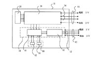
図1は、本発明の第1実施例を示すブロック図である。
図において、10は異常検出装置付きエンコーダで、回転角度の変位を検出する角度検出部20と、検出信号を波形整形し、変位に応じた信号を出力するエンコーダ回路30と、このエンコーダ回路30の基板への電源ラインとは別の電源ラインを持つ独立した基板上に載置された異常検出装置40で構成されている。また、異常検出装置40は、異常検出回路41と異常信号送信回路42で構成されている。
81はエンコーダ回路30に電源を供給する配線およびエンコーダ回路30の出力信号部34の配線からなる第1の配線ケーブルで、82は異常検出装置40に電源を供給する配線および異常信号出力部43の配線からなる第2の配線ケーブルで、第1の配線ケーブル81と第2の配線ケーブル82は別ケーブルで配線されている。
図2(a)は本実施例の角度検出部20の構成を示す斜視図である。
角度検出部20はLED21、固定スリット22、フォトダイオード23から構成され、図示しない被検出体の回転角度を、ハブ24に固定された回転ディスク25と固定スリット22とフォトダイオード23により検出して、エンコーダ回路30に電気信号として送出している。FIG. 1 is a block diagram showing a first embodiment of the present invention.
In the figure,
FIG. 2A is a perspective view showing the configuration of the
The
次に、本実施例の動作について説明する。
図1において、エンコーダ回路30から異常検出回路41に、エンコーダの異常状態を検出するためのエンコーダ各部の信号の状態を示すアナログ信号Aが入力されており、異常検出回路41はこのアナログ信号のレベルが予め設定した所定の範囲内であるかどうかを検出する。所定の範囲外であることが検出されると異常信号を生成し、異常信号送信回路に入力する。Next, the operation of this embodiment will be described.
In FIG. 1, an analog signal A indicating the signal state of each part of the encoder for detecting an abnormal state of the encoder is input from the
次に、アナログ信号Aの具体的例について述べる。
図2(b)は本実施例のエンコーダ回路30の一部の回路を示す回路図である。
図において31はフォトダイオード23で検出された信号を増幅するオペアンプ、32はこの増幅された信号を矩形波に変換するコンパレータである。オペアンプ31の出力は波形電圧信号として異常検出回路41に入力される。また、33はLEDの電流を検出する抵抗で、抵抗33の両端の電圧はLED電流信号として、異常検出回路41に入力される。
エンコーダの状態を示すアナログ信号Aの具体的な例として、下記のa)、b)、c)が挙げられる。
a)エンコーダ回路30の電源電圧を示す電源電圧信号。
b)角度検出部20からエンコーダ回路30に入力された被検出体(図示せず)の変位に応じた信号波形の電圧を示す波形電圧信号。
本実施例では角度検出部から送出された近似正弦波状の信号波形の最大値と最小値を検出した。
c)LED23の電流を示すLED電流信号。Next, a specific example of the analog signal A will be described.
FIG. 2B is a circuit diagram showing a part of the
In the figure, 31 is an operational amplifier for amplifying the signal detected by the
Specific examples of the analog signal A indicating the state of the encoder include the following a), b), and c).
a) A power supply voltage signal indicating the power supply voltage of the
b) A waveform voltage signal indicating the voltage of the signal waveform corresponding to the displacement of the detected object (not shown) input from the
In the present embodiment, the maximum value and the minimum value of the approximate sine wave signal waveform sent from the angle detection unit are detected.
c) LED current signal indicating the current of the
このように本実施例では、エンコーダ回路へ電源を供給する配線ケーブルの断線により、電源電圧信号に異常が発生しても、素子不良により波形電圧信号あるいはLED電流信号に異常が発生しても、異常検出装置の基板と配線が別なので、確実にエンコーダ回路の異常を検出して異常信号検出装置から異常信号を送出するので、信頼性が向上する。
また、アナログ信号を検出しているので、異常検出レベルを状況に合わせて設定でき、検出レベルに余裕を持たせることによって、本エンコーダを適用したシステムが誤動作を起こす前に、安全にシステムを停止することができる。
なお、本発明では、エンコーダ回路30の基板と異常検出装置40の基板は別基板として説明したが、構成部品を簡素化するため、同一基板上に独立して回路を構成しても同じ効果がある。
また、本実施例ではエンコーダ回路においてフォトダイオードの出力を増幅し、コンパレータで矩形波にする回路の例を示したが、フォトダイオードの出力を増幅したアナログ信号を出力する回路であっても良い。Thus, in this embodiment, even if an abnormality occurs in the power supply voltage signal due to disconnection of the wiring cable that supplies power to the encoder circuit, an abnormality occurs in the waveform voltage signal or the LED current signal due to an element failure, Since the substrate of the abnormality detection device is separate from the wiring, the abnormality of the encoder circuit is reliably detected and the abnormality signal is transmitted from the abnormality signal detection device, so that reliability is improved.
In addition, because an analog signal is detected, the abnormality detection level can be set according to the situation, and by providing a margin for the detection level, the system to which this encoder is applied can be safely stopped before malfunctioning. can do.
In the present invention, the substrate of the
In this embodiment, an example of a circuit that amplifies the output of the photodiode in the encoder circuit and converts the output of the photodiode into a rectangular wave is shown.
図3は、本発明の第2実施例を示すブロック図である。
図において、51は逆流防止用ダイオード、52は大容量コンデンサである。また、83は異常信号出力部43の配線からなる配線ケーブルで異常検出装置40への電源の配線を持たない。
本実施例が実施例1と異なる点は、実施例1ではエンコーダ回路30への電源と異常検出装置40への電源は、別々の電源を用いていたが、本実施例では、エンコーダ回路30の電源と異常検出装置40の電源とを共通化し、逆流防止用ダイオード51と大容量コンデンサ52によってエンコーダ回路30の電源から異常検出装置40に電源を供給している点である。FIG. 3 is a block diagram showing a second embodiment of the present invention.
In the figure, 51 is a backflow prevention diode, and 52 is a large capacity capacitor.
The difference between the present embodiment and the first embodiment is that, in the first embodiment, the power source for the
次に、本実施例の動作について説明する。
エンコーダ回路30の電源配線が断線などにより、供給不能になった場合、異常検出装置40は、大容量コンデンサ52の容量によってしばらくの間、電源が供給される。この電源が供給される間に異常検出装置40は、エンコーダ回路30の電源異常を検出し、異常信号を送出する。
本実施例では、エンコーダ回路の電源と異常検出装置の電源とを共通化しているので、電源からの配線数が減少し、断線の機会が少なくなるという効果がある。さらに、1つの電源で済むので構成が簡単になるという効果もある。Next, the operation of this embodiment will be described.
When the power supply wiring of the
In this embodiment, since the power supply of the encoder circuit and the power supply of the abnormality detection device are shared, there is an effect that the number of wires from the power supply is reduced and the chance of disconnection is reduced. Further, since only one power source is required, the configuration can be simplified.
図4は、本発明の第3実施例を示すブロック図である。
図において60は、環境異常検出素子である。
本実施例が第1実施例と異なる点は、異常検出装置付きエンコーダ10が、環境異常検出素子60を備えている点である。
本実施例では、環境異常検出素子60として、エンコーダの温度を検出する温度検出素子61と、エンコーダの振動を検出する振動検出素子62を設けた。温度検出素子61としてはサーミスタを用い、振動検出素子62としては加速度センサを用いた。FIG. 4 is a block diagram showing a third embodiment of the present invention.
In the figure,
The present embodiment is different from the first embodiment in that the
In this embodiment, a
次に、本実施例の動作について説明する。
温度検出素子61によってエンコーダ10の温度が検出され、温度に対応したアナログ信号が異常検出回路41に送られる。また、同様に、振動検出素子62によって、エンコーダ10の振動が検出され、振動に対応したアナログ信号が異常検出回路41に送られる。エンコーダ10の温度や振動が所定の範囲を超えると異常信号を生成する。これらの異常信号は異常信号送信回路42から送出される。Next, the operation of this embodiment will be described.
The temperature of the
このように本実施例では、異常検出装置付きエンコーダが振動検出素子を備えているので、エンコーダの温度上昇や振動等の環境異常による電気部品や機械部品の不具合発生および回路動作不良を未然に防止することが出来、エンコーダの信頼性をさらに向上させる事が出来る。 As described above, in this embodiment, the encoder with the abnormality detection device includes the vibration detection element, so that it is possible to prevent the occurrence of malfunctions in the electrical parts and mechanical parts due to environmental abnormalities such as the temperature rise of the encoder and vibrations and the malfunction of the circuit. It is possible to improve the reliability of the encoder.
図5は、本発明の第4実施例を示すブロック図である。
図において、71は正常信号発生回路である。
本実施例が第1実施例と異なる点は、異常検出装置40が、電源投入してから一定時間後に、異常検出装置付きエンコーダ10が正常に動作している事を知らせる正常信号発生回路71を備えている点である。FIG. 5 is a block diagram showing a fourth embodiment of the present invention.
In the figure,
The present embodiment is different from the first embodiment in that a normal
次に本実施例の動作について説明する。
図6は本実施例の動作を示すタイムチャートである。
図において、711は異常検出装置40の電源電圧、712は正常信号発生回路の出力信号である。
異常検出装置40に電源が投入されると、正常信号発生回路71は異常検出装置40が正常に動作していることを検出し、電源の立ち上がりから正常信号発生回路71で設定したT秒後にハイレベルとなる信号を送出する。電源投入後、直ちにハイレベルにすると、異常検出装置40が故障してハイレベルの信号を送出している可能性があるため、T秒と言う一定時間後に異常検出装置40から正常に動作している事を示す信号を送出する機能を持たせることで検出の信頼性を高めた。
このように本実施例では、異常検出装置が正常信号発生回路を備え、電源投入時に異常検出装置が正常に動作しているかどうかを検出しているので、異常検出装置の信頼性が向上し、エンコーダの信頼性をさらに向上させる事が出来る。Next, the operation of this embodiment will be described.
FIG. 6 is a time chart showing the operation of this embodiment.
In the figure,
When the
As described above, in this embodiment, the abnormality detection device includes a normal signal generation circuit, and detects whether the abnormality detection device is operating normally when the power is turned on, thereby improving the reliability of the abnormality detection device, The reliability of the encoder can be further improved.
図7は、本発明の第5実施例を示すブロック図である。
図において、72は図示しない制御装置と双方向で異常検出装置40の動作を調べるための双方向異常信号発生回路である。
本実施例が第4実施例と異なる点は、第4実施例では、異常検出装置40が、正常信号発生回路71を備えていたが、本実施例では双方向異常信号発生回路72を備え、双方向通信で異常検出装置40の動作をチェックしている点である。FIG. 7 is a block diagram showing a fifth embodiment of the present invention.
In the figure,
The difference between this embodiment and the fourth embodiment is that, in the fourth embodiment, the
上記問題を解決するため、本発明は、次のように構成したものである。
請求項1に記載の発明は、被検出体の回転角度または直線位置等の変位を検出するエンコーダであって、前記被検出体の変位に応じた信号を検出する検出部と、前記検出部からの信号を処理し変位に応じた信号を出力するエンコーダ回路と、前記エンコーダの異常状態を検出する異常検出装置とを備えたエンコーダにおいて、前記エンコーダ回路の電源と前記異常検出装置の電源は、それぞれ独立した別電源で供給されるものである。
また、請求項2に記載の発明は、被検出体の回転角度または直線位置等の変位を検出するエンコーダであって、前記被検出体の変位に応じた信号を検出する検出部と、前記検出部からの信号を処理し変位に応じた信号を出力するエンコーダ回路と、前記エンコーダの異常状態を検出する異常検出装置と、前記エンコーダ回路の電源及び出力信号部に接続される第1の配線ケーブルと、前記異常検出装置の電源及び異常信号出力部に接続される第2の配線ケーブルとを備えたエンコーダにおいて、前記エンコーダ回路の電源と前記異常検出装置の電源は、それぞれ独立した別電源で供給され、かつ、前記第1の配線ケーブルと、前記第2の配線ケーブルは、それぞれ別ケーブルを使用するものである。
また、請求項3に記載の発明は、被検出体の回転角度または直線位置等の変位を検出するエンコーダであって、前記被検出体の変位に応じた信号を検出する検出部と、前記検出部からの信号を処理し変位に応じた信号を出力するエンコーダ回路と、前記エンコーダの異常状態を検出する異常検出装置とを備えたエンコーダにおいて、前記異常検出装置の電源は、前記エンコーダ回路の電源から、この電源に接続された逆流防止ダイオードとこの逆流防止ダイオードを通して得られた電荷を蓄積する大容量コンデンサから構成される回路にて供給されることを特徴とするものである。
また、請求項4に記載の発明は、前記エンコーダの異常状態を検出する信号は、前記エンコーダ回路の電源電圧信号であることを特徴とするものである。
また、請求項5に記載の発明は、前記エンコーダの異常状態を検出する信号は、前記角度検出部で検出された波形電圧信号であることを特徴とするものである。
また、請求項6に記載の発明は、前記エンコーダの異常状態を検出する信号は、前記角度検出部のLEDに流れる電流に対応したLED電流信号であることを特徴とするものである。
また、請求項7に記載の発明は、前記異常検出装置は、前記異常検出装置付きエンコーダの環境状態を検出する環境異常検出素子を備えたものである。
また、請求項8に記載の発明は、前記環境異常検出素子を、温度検出素子とするものである。
また、請求項9に記載の発明は、前記環境異常検出素子を、振動検出素子とするものである。
また、請求項10に記載の発明は、前記異常検出装置は、電源投入してから一定時間後に正常動作している事を知らせる信号を送出する機能を具備するものである。
また、請求項11に記載の発明は、前記異常検出装置は、異常検出信号のやり取りを双方向通信で行なう機能を具備する具備するものである。
また、請求項12に記載の発明は、請求項1乃至11のいずれか1項に記載の異常検出装置付きエンコーダを備えたモータと、前記異常検出装置付きエンコーダに接続された制御装置と、前記制御装置からの制御信号によって前記モータを駆動するモータ駆動装置と、を備えた制御システムにおいて、前記制御装置は前記異常検出装置付きエンコーダからの異常信号を検出し、異常状態に応じて前記モータを制御することを特徴とするものである。
In order to solve the above problems, the present invention is configured as follows.
The invention according to claim 1 is an encoder that detects a displacement such as a rotation angle or a linear position of a detected object, a detection unit that detects a signal corresponding to the displacement of the detected object, and the detection unit In the encoder comprising an encoder circuit that processes the signal of and outputs a signal corresponding to the displacement, and an abnormality detection device that detects an abnormal state of the encoder, the power source of the encoder circuit and the power source of the abnormality detection device are respectively It is supplied by an independent separate power source.
The invention according to claim 2 is an encoder that detects displacement such as a rotation angle or a linear position of a detected object, a detection unit that detects a signal corresponding to the displacement of the detected object, and the detection An encoder circuit that processes a signal from the unit and outputs a signal corresponding to the displacement, an abnormality detection device that detects an abnormal state of the encoder, and a first wiring cable connected to a power source and an output signal unit of the encoder circuit When, in encoder and a second wiring cable connected to the power source and the abnormality signal output of the abnormality detecting device, the power supply to the abnormality detecting device of the encoder circuit is supplied in a separate power supply which is independent In addition, separate cables are used for the first wiring cable and the second wiring cable, respectively.
According to a third aspect of the present invention, there is provided an encoder that detects a displacement such as a rotation angle or a linear position of a detected object, a detection unit that detects a signal corresponding to the displacement of the detected object, and the detection An encoder including an encoder circuit that processes a signal from a unit and outputs a signal corresponding to a displacement, and an abnormality detection device that detects an abnormal state of the encoder, the power source of the abnormality detection device is a power source of the encoder circuit From this, it is supplied by a circuit composed of a backflow prevention diode connected to the power supply and a large-capacitance capacitor for accumulating charges obtained through the backflow prevention diode.
According to a fourth aspect of the present invention, the signal for detecting an abnormal state of the encoder is a power supply voltage signal of the encoder circuit.
The invention described in
The invention described in claim 6 is characterized in that the signal for detecting the abnormal state of the encoder is an LED current signal corresponding to the current flowing through the LED of the angle detection unit.
According to a seventh aspect of the present invention, the abnormality detection device includes an environmental abnormality detection element that detects an environmental state of the encoder with the abnormality detection device.
In the invention according to claim 8, the environmental abnormality detection element is a temperature detection element.
According to a ninth aspect of the present invention, the environmental abnormality detection element is a vibration detection element.
The invention according to
The invention according to claim 11 is characterized in that the abnormality detection device has a function of exchanging abnormality detection signals by bidirectional communication.
A twelfth aspect of the invention provides a motor including the encoder with the abnormality detection device according to any one of the first to eleventh aspects, a control device connected to the encoder with the abnormality detection device, And a motor drive device that drives the motor in response to a control signal from the control device, wherein the control device detects an abnormality signal from the encoder with the abnormality detection device, and controls the motor according to an abnormal state. It is characterized by controlling.
このように本実施例では、異常検出装置が双方向異常信号発生回路を備え、常に異常検出装置自身の動作をチェックしているので、エンコーダの信頼性をさらに向上させる事が出来る。 As described above, in this embodiment, the abnormality detection device includes the bidirectional abnormality signal generation circuit and always checks the operation of the abnormality detection device itself, so that the reliability of the encoder can be further improved.
図9は、本発明の第6実施例を示すブロック図である。
図において、90は制御装置、100はモータ駆動装置、110は図示しない工作機械等の産業機械に取り付けられ、本発明の異常検出装置付きエンコーダ10を装備したモータである。制御装置90は受け側異常信号検出回路部91と、受け側制御回路92とを備えている。FIG. 9 is a block diagram showing a sixth embodiment of the present invention.
In the figure, 90 is a control device, 100 is a motor drive device, and 110 is a motor mounted on an industrial machine such as a machine tool (not shown) and equipped with the
次に、本実施例の動作について説明する。
異常検出装置付きエンコーダ10から受け側異常信号検出回路部91に異常信号93が送信されると、受け側制御回路92において、モータ110を速やかに停止させるあるいは非常停止する等、どのように対応すべきかを判定し、異常信号出力94をモータ駆動装置100に送信する。Next, the operation of this embodiment will be described.
When the
このように本実施例では、制御装置の受け側制御回路によって生成された異常信号出力によって、制御装置が、どの様に対応すべきか判定し、その結果を異常信号出力として送出し、モータを速やかに停止させるの等の処理を行うので、安全で、高信頼性の制御システムを構成することができる。 As described above, in this embodiment, the control device determines how to deal with the abnormal signal output generated by the control circuit on the receiving side of the control device, sends the result as the abnormal signal output, and promptly turns the motor on. Therefore, a safe and highly reliable control system can be configured.
半導体製造装置、ロボット、NC工作機械など多くの産業機械に使用するモータの回転位置又は直線変位を検出するエンコーダに適用できる。
なお、各実施例として、回転型光学式エンコーダについて述べたが、回転型、直線型のいずれか一方に限定されず、また、光学式、磁気式のいずれか一方に限定されないことは言うまでもない。The present invention can be applied to an encoder that detects the rotational position or linear displacement of a motor used in many industrial machines such as semiconductor manufacturing equipment, robots, and NC machine tools.
In addition, as each Example, although the rotary optical encoder was described, it cannot be overemphasized that it is not limited to any one of a rotation type and a linear type, and is not limited to any one of an optical type and a magnetic type.
Claims (12)
前記被検出体の変位に応じた信号を検出する検出部と、
前記検出部からの信号を処理し変位に応じた信号を出力するエンコーダ回路と、
前記エンコーダの異常状態を検出する異常検出装置と、
を備え、
前記エンコーダ回路の電源と前記異常検出装置の電源は、それぞれ独立した別電源で供給される、異常検出装置付きエンコーダ。An encoder that detects a rotation angle or a linear position displacement of a detected object,
A detection unit for detecting a signal corresponding to the displacement of the detected object;
An encoder circuit that processes a signal from the detection unit and outputs a signal corresponding to the displacement;
An abnormality detection device for detecting an abnormal state of the encoder;
With
The encoder with an abnormality detection device, wherein the power source of the encoder circuit and the power source of the abnormality detection device are supplied by separate independent power sources.
前記異常検出装置の電源及び異常信号出力部に接続される第2の配線ケーブルと、
を更に備え、
前記第1の配線ケーブルと前記第2の配線ケーブルとは、それぞれ別ケーブルを使用する、請求項1に記載の異常検出装置付きエンコーダ。A first wiring cable connected to the power supply and output signal section of the encoder circuit;
A second wiring cable connected to a power source and an abnormality signal output unit of the abnormality detection device;
Further comprising
The encoder with an abnormality detection device according to claim 1, wherein the first wiring cable and the second wiring cable are different cables.
前記被検出体の変位に応じた信号を検出する検出部と、
前記検出部からの信号を処理し変位に応じた信号を出力するエンコーダ回路と、
前記エンコーダの異常状態を検出する異常検出装置と、
を備え、
前記異常検出装置の電源は、前記エンコーダ回路の電源から、この電源に接続された逆流防止ダイオードとこの逆流防止ダイオードを通して得られた電荷を蓄積する大容量コンデンサを有する回路にて供給される、異常検出装置付きエンコーダ。An encoder that detects a rotation angle or a linear position displacement of a detected object,
A detection unit for detecting a signal corresponding to the displacement of the detected object;
An encoder circuit that processes a signal from the detection unit and outputs a signal corresponding to the displacement;
An abnormality detection device for detecting an abnormal state of the encoder;
With
The power supply of the abnormality detection device is supplied from a power supply of the encoder circuit by a circuit having a backflow prevention diode connected to the power supply and a large-capacitance capacitor for accumulating charges obtained through the backflow prevention diode. Encoder with detector.
前記異常検出装置付きエンコーダに接続された制御装置と、
前記制御装置からの制御信号によって前記モータを駆動するモータ駆動装置と、
を備え、
前記制御装置は、前記異常検出装置付きエンコーダからの異常信号を検出し、異常状態に応じて前記モータを制御する、制御システム。A motor comprising the encoder with an abnormality detection device according to any one of claims 1 to 11,
A control device connected to the encoder with the abnormality detection device;
A motor drive device for driving the motor by a control signal from the control device;
With
The said control apparatus is a control system which detects the abnormal signal from the encoder with the said abnormality detection apparatus, and controls the said motor according to an abnormal condition.
Priority Applications (1)
| Application Number | Priority Date | Filing Date | Title |
|---|---|---|---|
| JP2007525922A JP4968069B2 (en) | 2005-07-19 | 2006-06-27 | Encoder with abnormality detection device and control system therefor |
Applications Claiming Priority (4)
| Application Number | Priority Date | Filing Date | Title |
|---|---|---|---|
| JP2005207979 | 2005-07-19 | ||
| JP2005207979 | 2005-07-19 | ||
| JP2007525922A JP4968069B2 (en) | 2005-07-19 | 2006-06-27 | Encoder with abnormality detection device and control system therefor |
| PCT/JP2006/312812 WO2007010716A1 (en) | 2005-07-19 | 2006-06-27 | Encoder having abnormality detection device and its control system thereof |
Publications (2)
| Publication Number | Publication Date |
|---|---|
| JPWO2007010716A1 JPWO2007010716A1 (en) | 2009-01-29 |
| JP4968069B2 true JP4968069B2 (en) | 2012-07-04 |
Family
ID=37668602
Family Applications (1)
| Application Number | Title | Priority Date | Filing Date |
|---|---|---|---|
| JP2007525922A Expired - Fee Related JP4968069B2 (en) | 2005-07-19 | 2006-06-27 | Encoder with abnormality detection device and control system therefor |
Country Status (5)
| Country | Link |
|---|---|
| US (1) | US20090229134A1 (en) |
| JP (1) | JP4968069B2 (en) |
| CN (1) | CN101223418A (en) |
| DE (1) | DE112006001925T5 (en) |
| WO (1) | WO2007010716A1 (en) |
Families Citing this family (16)
| Publication number | Priority date | Publication date | Assignee | Title |
|---|---|---|---|---|
| JP4574636B2 (en) * | 2007-03-14 | 2010-11-04 | 株式会社日立製作所 | Elevator equipment |
| JP4995605B2 (en) * | 2007-03-16 | 2012-08-08 | オークマ株式会社 | Abnormality detection device for rotary absolute encoder |
| US8322214B2 (en) | 2008-04-04 | 2012-12-04 | Panasonic Corporation | Sensor device |
| US8131508B2 (en) * | 2009-02-05 | 2012-03-06 | Panasonic Corporation | Sensor apparatus |
| JP4337952B1 (en) * | 2009-02-05 | 2009-09-30 | パナソニック株式会社 | Sensor device |
| JP4386143B1 (en) * | 2009-02-05 | 2009-12-16 | パナソニック株式会社 | Sensor device |
| CN101833049B (en) * | 2009-02-09 | 2014-01-15 | 富士电机株式会社 | Anomaly monitoring device |
| JP2011154005A (en) * | 2010-01-28 | 2011-08-11 | Nikon Corp | Encoder |
| JP6193000B2 (en) * | 2013-06-12 | 2017-09-06 | 株式会社日立製作所 | Encoder abnormality detection device and elevator apparatus using encoder abnormality detection device |
| JP2016052223A (en) * | 2014-09-02 | 2016-04-11 | ソムフィ株式会社 | Motor drive device |
| JP6857818B2 (en) * | 2016-10-24 | 2021-04-14 | パナソニックIpマネジメント株式会社 | Encoder abnormality detection method, abnormality detection device, and robot control system |
| US10578463B2 (en) * | 2016-12-19 | 2020-03-03 | Microchip Technology Incorporated | Detection of defects in motor position decoder system |
| JP6434571B1 (en) * | 2017-06-23 | 2018-12-05 | ファナック株式会社 | Absolute encoder equipped with an abnormality detector that detects abnormalities in current consumption |
| JP6787939B2 (en) | 2018-02-20 | 2020-11-18 | ファナック株式会社 | Encoder and backup current abnormality judgment method |
| CN109471049B (en) * | 2019-01-09 | 2021-09-17 | 南京航空航天大学 | Satellite power supply system anomaly detection method based on improved stacked self-encoder |
| DE102019209607A1 (en) * | 2019-07-01 | 2021-01-07 | Dr. Johannes Heidenhain Gmbh | Position measuring device and method for operating a position measuring device |
Citations (3)
| Publication number | Priority date | Publication date | Assignee | Title |
|---|---|---|---|---|
| JPS63172913U (en) * | 1987-04-30 | 1988-11-10 | ||
| JPH0325317A (en) * | 1989-06-23 | 1991-02-04 | Nec Eng Ltd | Rotational position detecting circuit |
| JP2000339196A (en) * | 1999-05-31 | 2000-12-08 | Nec Corp | Abnormality monitoring system |
Family Cites Families (8)
| Publication number | Priority date | Publication date | Assignee | Title |
|---|---|---|---|---|
| JPH04125408A (en) * | 1990-09-17 | 1992-04-24 | Futaba Corp | Linear scale device for measuring length |
| DE10056947A1 (en) * | 2000-11-17 | 2002-05-23 | Optolab Licensing Gmbh | Method for mounting a material measure with dividing structures and a scanner head with scanning structures for scanning the dividing structures fastens a dividing support on a first part and the scanner head on a second part |
| DE10123292B4 (en) * | 2001-05-13 | 2010-07-22 | Anton Rodi | sensor system |
| DE10244583A1 (en) * | 2002-09-25 | 2004-04-08 | Dr. Johannes Heidenhain Gmbh | Measuring system and method for checking its function |
| JP4142942B2 (en) * | 2002-12-09 | 2008-09-03 | 株式会社ソキア | Rotary encoder |
| US6973731B2 (en) * | 2003-12-30 | 2005-12-13 | Alps Electric Co., Ltd. | Encoder |
| DE102004024954A1 (en) * | 2004-05-21 | 2005-12-08 | Robert Bosch Gmbh | Sensor for a transmission control in particular of a motor vehicle |
| DE102008004454B4 (en) * | 2008-01-15 | 2020-02-13 | Asm Automation Sensorik Messtechnik Gmbh | Angle sensor circuit |
-
2006
- 2006-06-27 WO PCT/JP2006/312812 patent/WO2007010716A1/en active Application Filing
- 2006-06-27 US US11/996,355 patent/US20090229134A1/en not_active Abandoned
- 2006-06-27 CN CNA2006800263867A patent/CN101223418A/en active Pending
- 2006-06-27 JP JP2007525922A patent/JP4968069B2/en not_active Expired - Fee Related
- 2006-06-27 DE DE112006001925T patent/DE112006001925T5/en not_active Withdrawn
Patent Citations (3)
| Publication number | Priority date | Publication date | Assignee | Title |
|---|---|---|---|---|
| JPS63172913U (en) * | 1987-04-30 | 1988-11-10 | ||
| JPH0325317A (en) * | 1989-06-23 | 1991-02-04 | Nec Eng Ltd | Rotational position detecting circuit |
| JP2000339196A (en) * | 1999-05-31 | 2000-12-08 | Nec Corp | Abnormality monitoring system |
Also Published As
| Publication number | Publication date |
|---|---|
| CN101223418A (en) | 2008-07-16 |
| WO2007010716A1 (en) | 2007-01-25 |
| US20090229134A1 (en) | 2009-09-17 |
| JPWO2007010716A1 (en) | 2009-01-29 |
| DE112006001925T5 (en) | 2008-05-21 |
Similar Documents
| Publication | Publication Date | Title |
|---|---|---|
| JP4968069B2 (en) | Encoder with abnormality detection device and control system therefor | |
| US8659254B2 (en) | Servo system, servo motor driving device, safety unit and method for controlling servo system | |
| JP5994305B2 (en) | Rotary encoder and error detection method for rotary encoder | |
| US8350713B2 (en) | Numerical controller having a function for determining machine abnormality from signals obtained from a plurality of sensors | |
| JP4926166B2 (en) | Interface module for mounting inside or outside the motor | |
| CN108931261B (en) | Encoder system and abnormality detection method | |
| JP2007219991A (en) | Abnormal load detection device | |
| CN112147507B (en) | Motor band-type brake state detection method and system based on closed-loop control | |
| JPS58205211A (en) | Pulse encoder with fault self-diagnosing function | |
| JP5215188B2 (en) | Monitoring device for drive unit | |
| JP4525593B2 (en) | Control system by serial communication | |
| JP6434445B2 (en) | Machine tool control device having failure diagnosis function of sensor for detecting one rotation signal | |
| JP6641920B2 (en) | Power converter | |
| CN115004540A (en) | Device and method for operating a drive system | |
| KR101207460B1 (en) | A telescope mount control system | |
| KR102578130B1 (en) | Encoder with self-diagnostic fuction | |
| JP5043636B2 (en) | Rotary encoder | |
| JP7403825B2 (en) | Encoder and control system | |
| JP2000193489A (en) | Position detector and cable used therefor | |
| WO2023053489A1 (en) | Electronic control device, and method for diagnosing electronic control device | |
| JP4912053B2 (en) | Rotating electric machine with power transmission mechanism | |
| JP4869008B2 (en) | Vibration diagnosis system for rotating machinery | |
| JP5134926B2 (en) | Monitoring system and controller | |
| JP5043640B2 (en) | Rotary encoder | |
| KR102063110B1 (en) | Interface controlling device and method for monitoring driving voltage thereby |
Legal Events
| Date | Code | Title | Description |
|---|---|---|---|
| A521 | Request for written amendment filed |
Free format text: JAPANESE INTERMEDIATE CODE: A523 Effective date: 20090213 |
|
| A621 | Written request for application examination |
Free format text: JAPANESE INTERMEDIATE CODE: A621 Effective date: 20090213 |
|
| A131 | Notification of reasons for refusal |
Free format text: JAPANESE INTERMEDIATE CODE: A131 Effective date: 20110905 |
|
| A521 | Request for written amendment filed |
Free format text: JAPANESE INTERMEDIATE CODE: A523 Effective date: 20111031 |
|
| A131 | Notification of reasons for refusal |
Free format text: JAPANESE INTERMEDIATE CODE: A131 Effective date: 20111206 |
|
| A521 | Request for written amendment filed |
Free format text: JAPANESE INTERMEDIATE CODE: A523 Effective date: 20120106 |
|
| TRDD | Decision of grant or rejection written | ||
| A01 | Written decision to grant a patent or to grant a registration (utility model) |
Free format text: JAPANESE INTERMEDIATE CODE: A01 Effective date: 20120306 |
|
| A01 | Written decision to grant a patent or to grant a registration (utility model) |
Free format text: JAPANESE INTERMEDIATE CODE: A01 |
|
| A61 | First payment of annual fees (during grant procedure) |
Free format text: JAPANESE INTERMEDIATE CODE: A61 Effective date: 20120319 |
|
| FPAY | Renewal fee payment (event date is renewal date of database) |
Free format text: PAYMENT UNTIL: 20150413 Year of fee payment: 3 |
|
| R150 | Certificate of patent or registration of utility model |
Free format text: JAPANESE INTERMEDIATE CODE: R150 |
|
| LAPS | Cancellation because of no payment of annual fees |