JP4967972B2 - Continuous I-girder bridge, I-girder structure near its intermediate fulcrum and its construction method - Google Patents
Continuous I-girder bridge, I-girder structure near its intermediate fulcrum and its construction method Download PDFInfo
- Publication number
- JP4967972B2 JP4967972B2 JP2007261240A JP2007261240A JP4967972B2 JP 4967972 B2 JP4967972 B2 JP 4967972B2 JP 2007261240 A JP2007261240 A JP 2007261240A JP 2007261240 A JP2007261240 A JP 2007261240A JP 4967972 B2 JP4967972 B2 JP 4967972B2
- Authority
- JP
- Japan
- Prior art keywords
- girder
- web
- concrete
- intermediate fulcrum
- lower flange
- Prior art date
- Legal status (The legal status is an assumption and is not a legal conclusion. Google has not performed a legal analysis and makes no representation as to the accuracy of the status listed.)
- Active
Links
Images


Description
本発明は、橋梁等の土木構造物およびその構築方法に関し、特に、連続I桁橋、その中間支点近傍のI桁の構造およびその構築方法に関するものである。 The present invention relates to a civil structure such as a bridge and a construction method thereof, and more particularly to a continuous I-girder bridge, a structure of an I-girder near an intermediate fulcrum, and a construction method thereof.
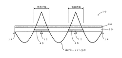
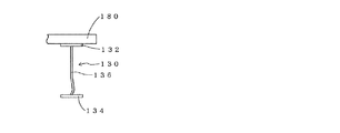
図17に示すように、連続I桁橋10の中間支点12近傍には大きな負の曲げモーメントが生じる。この負の曲げモーメントにより、図18〜図20に示すI桁130のウェブ136下部から下フランジ134にかけての桁断面には大きな圧縮力が作用するため、図18に示すように下フランジ134が局部座屈したり、図19に示すようにウェブ136下部が局部座屈したり、図20に示すようにI桁130全体が横倒れ座屈、横ねじれ座屈等の横座屈を起こす可能性がある。特に、連続I桁橋10のスパンが比較的長い場合において、I桁130に高強度鋼などを適用する場合には、このような問題が顕著となる。図18〜図20において、132は上フランジ、180はI桁130の上に設置する床版である。
As shown in FIG. 17, a large negative bending moment is generated in the vicinity of the intermediate fulcrum 12 of the continuous I
これに対する従来技術1として、中間支点12近傍において、
(1)下フランジ134の板厚を大きくする。
(2)ウェブ136の板厚を大きくする。
(3)横桁や横溝等の間隔を小さくして密に配置する。
等の対策がある。
As
(1) The plate thickness of the lower flange 134 is increased.
(2) Increase the thickness of the web 136.
(3) The gaps such as the horizontal beams and the horizontal grooves are made smaller and densely arranged.
There are measures such as.
また、従来技術2として、特許文献1に記載された橋梁用連続桁が挙げられる。この橋梁用連続桁は、上下のフランジとウェブとを有して橋軸方向に延び、1又は複数の中間支点で支持される鋼製の桁本体を備え、この桁本体の上記中間支点の周辺には、垂直、水平鉄筋の全て若しくは一部を埋設してなる鉄筋コンクリートが、上記ウェブに添うようにして打設されており、上記垂直鉄筋が、垂直に延びると共に上下端が上下のフランジにそれぞれ連結され、上記水平鉄筋が、上記橋軸方向に延び上記垂直鉄筋と直交されていることを特徴とし、上記中間支点周辺の被支持領域が、鉄筋コンクリートで補強されている。
Moreover, as the
また、従来技術3として、特許文献2や特許文献3を挙げることができ、特許文献2や特許文献3には、少なくとも一対のI桁が橋軸方向に配設された連続桁橋において、支承による被支持部近傍の前記一対のI桁の下フランジ間に、補強板(特許文献2)やコンクリート版(特許文献3)を架設固定し、箱形断面として補強することが記載されている。
Further,
さらに、従来技術4として、特許文献4を挙げることができ、特許文献4には、箱桁橋梁において、中間支点周辺の領域の鋼箱桁の内部空間全体をコンクリートで埋め尽くして補強することが記載されている。
Furthermore,
また、従来技術5として、特許文献5を挙げることができ、特許文献5には、I桁の下フランジ上面にプレキャスト板を配設して、下フランジの局部座屈を防止した、中間支点近傍のI桁の構造が記載されている。 Further, Patent Document 5 can be cited as the prior art 5. In Patent Document 5, a precast plate is disposed on the upper surface of the lower flange of the I-girder to prevent local buckling of the lower flange, and in the vicinity of the intermediate fulcrum. The I-digit structure is described.
しかしながら、従来技術1には、次のような問題点がある。
(A)下フランジ及びウェブの板厚を大きくする場合には、鋼重が大幅に増え、また、断面ごとの溶接接合やボルト接合による作業が大変になるため、工数が増え、工費が増大することになる。
(B)横桁や横溝等の間隔を小さくして密に配置する場合には、横桁や横溝等の個数が増えるため、鋼重および工数が増え、工費が増大することになる。
However, the
(A) When the plate thickness of the lower flange and web is increased, the steel weight increases significantly, and the work by welding and bolting for each cross section becomes difficult, so the number of man-hours increases and the construction cost increases. It will be.
(B) In the case where the gaps such as the cross beams and the horizontal grooves are made small and densely arranged, the number of the cross beams and the horizontal grooves increases, so that the steel weight and the man-hour increase, and the work cost increases.
また、特許文献1に記載の従来技術2には、次のような問題点がある。
Further, the
従来技術2は、垂直鉄筋の上下端を上下のフランジにそれぞれ直接、あるいは、短鉄筋とカプラーを介して溶接等により連結する必要がある。一般に、桁橋の上下フランジ間は2〜3m程度となるため、垂直鉄筋も2〜3m程度の長さとなる。2〜3mの長さの長い鉄筋を上下のフランジへ直接溶接する作業は、煩雑かつ困難であり、精度確保も難しい。また、短鉄筋とカプラーを介して連結する場合も、まず短鉄筋を溶接し、さらに長い鉄筋をカプラーを介して連結する必要があるため、工数が増えるばかりか、短鉄筋の取付位置や角度等に高い精度が要求される。また、特許文献1の図6には、垂直鉄筋の下側部だけをコンクリートに埋設し、桁本体が非支持領域において圧縮応力で座屈しないようにした実施形態が記載されているが、垂直鉄筋の上側部は大気中に露出しており、腐食が懸念される。
In the
また、特許文献2及び3に記載された技術(従来技術3)は、隣接するI桁の下フランジ間に補強板やコンクリート版を架設固定して、箱形断面を形成してI桁を補強する技術であるが、箱型断面であるため、I桁のウェブの局部座屈を防ぐ効果を向上させるために、架設固定する補強板やコンクリート版の厚さを増すと、上部工の重量が大幅に増えてしまう。
In addition, the technique described in
また、特許文献4に記載された技術(従来技術4)は、中間支点周辺の領域の鋼箱桁の内部空間全体をコンクリートで埋め尽くして補強する技術であるが、箱桁のウェブを外側から拘束しておらず、箱桁のウェブの局部座屈を防ぐ効果が十分とはいえない。 The technique described in Patent Document 4 (Prior Art 4) is a technique in which the entire interior space of the steel box girder in the region around the intermediate fulcrum is filled with concrete to reinforce the web. It is not restrained and the effect of preventing local buckling of the box girder web is not sufficient.
また、特許文献5に記載された技術(従来技術5)は、I桁の下フランジの上にプレキャスト板を配設して、I桁のウェブを両側から挟み込んでいるが、特許文献3に記載された技術とは異なり箱形断面を形成しておらず、I桁のウェブを挟み込む範囲を広くするためにプレキャスト板の厚さを厚くしても、特許文献3に記載された技術ほどは、上部工の重量は増加しない。しかし、プレキャスト板を用いていることから、I桁のウェブを両側から遊びなく挟み込むことは難しく、I桁のウェブを十分に拘束することは難しい。また、プレキャスト板を用いていることから、I桁の長手方向と直交する各断面において鋼とコンクリートの合成効果を高めることには限界がある。
In the technique described in Patent Document 5 (Prior Art 5), a precast plate is disposed on the lower flange of the I-girder and the I-girder web is sandwiched from both sides. Unlike the technology that has been made, the box-shaped cross section is not formed, and even if the thickness of the precast plate is increased in order to widen the range in which the I-digit web is sandwiched, the technology described in
本発明は、前記従来の問題点を解決するべくなされたもので、鋼重、上部工の重量の増加、工数、工費を低減しつつ、施工の容易さや設置する鋼部材の腐食防止にも配慮した上で、1又は複数の中間支点によって支持される連続I桁橋の、負の曲げモーメントが作用する中間支点近傍において、I桁の下フランジ及びウェブ下部の局部座屈、I桁全体の横座屈の発生を防止するとともに、I桁の長手方向と直交する各断面における鋼とコンクリートの合成効果を高めて、連続I桁橋の中間支点近傍のI桁の耐荷力を向上させることを課題とする。 The present invention has been made to solve the above-mentioned conventional problems, and considers the ease of construction and the prevention of corrosion of steel members to be installed while reducing the weight of steel, superstructure, man-hour and cost. Then, in the vicinity of the intermediate fulcrum where the negative bending moment acts on the continuous I-girder bridge supported by one or more intermediate fulcrums, local buckling of the lower flange of the I-girder and the lower part of the web, and the lateral seating of the entire I-girder The problem is to improve the load carrying capacity of the I-girder near the intermediate fulcrum of the continuous I-girder bridge while preventing the occurrence of bending and enhancing the composite effect of steel and concrete in each cross section orthogonal to the longitudinal direction of the I-girder. To do.
本発明に係る、連続I桁橋における中間支点近傍のI桁の構造の第1の態様は、上フランジ、下フランジ、ウェブ、鉛直補剛材を備えたI桁と床版によって構成され、両端の端支点と1又は複数の中間支点とによって支持される連続I桁橋の、負の曲げモーメントが作用する中間支点近傍において、ウェブの下部に貫通孔を複数個設け、該貫通孔に鉄筋を挿通し、下フランジの上面にずれ止めを複数個配設し、該鉄筋および該ずれ止めを含み、下フランジの上面、ウェブの下部、鉛直補剛材の下部で囲まれる空間にフレッシュコンクリートを打設して、前記鉄筋全体、前記ずれ止め全体、前記下フランジの上面、前記ウェブの下部、前記鉛直補剛材の下部を、前記フレッシュコンクリートが硬化してなるコンクリートと一体化させてなり、下フランジおよびウェブ下部の局部座屈ならびにI桁全体の横座屈を防止して、I桁の耐荷力を向上させることを特徴とする。 The first aspect of the structure of the I-girder near the intermediate fulcrum in the continuous I-girder bridge according to the present invention is constituted by an I-girder having an upper flange, a lower flange, a web, a vertical stiffener, and a floor slab. In the vicinity of the intermediate fulcrum of the continuous I-girder bridge supported by the end fulcrum and one or a plurality of intermediate fulcrums, where a negative bending moment acts, a plurality of through holes are provided in the lower part of the web, and reinforcing bars are provided in the through holes. Insert a plurality of stoppers on the upper surface of the lower flange, and insert fresh concrete into the space that includes the reinforcing bars and the stoppers and is surrounded by the upper surface of the lower flange, the lower part of the web, and the lower part of the vertical stiffener. The entire rebar, the entire slip stopper, the upper surface of the lower flange, the lower part of the web, and the lower part of the vertical stiffener are integrated with concrete obtained by curing the fresh concrete, To prevent lunge and local buckling and I digit overall Lateral Buckling of the web bottom, characterized in that to improve the load bearing capacity of the I girder.
ここで、連続I桁橋は、正確には上部工と下部工からなるが、本明細書においては、「連続I桁橋の上部工」を「連続I桁橋」と記載している。 Here, the continuous I girder bridge is made up of an upper work and a lower work, but in this specification, “the upper work of the continuous I girder bridge” is described as “continuous I girder bridge”.
前記第1の態様において、前記フレッシュコンクリートが硬化してなる前記コンクリートを、塑性中立軸より下の領域である圧縮域内に制限することにより、重量増加を抑えつつ、下フランジおよびウェブ下部の局部座屈ならびにI桁全体の横座屈を効果的に防止することができる。 In the first aspect, the concrete formed by curing the fresh concrete is restricted to a compression region that is a region below the plastic neutral axis, thereby suppressing an increase in weight, and a local seat below the lower flange and the web. Bending and lateral buckling of the entire I-girder can be effectively prevented.
ここで、塑性中立軸とは、曲げモーメントによる塑性応力状態における断面の中立軸である。 Here, the plastic neutral axis is a neutral axis of a section in a plastic stress state caused by a bending moment.
本発明に係る、連続I桁橋における中間支点近傍のI桁の構造の第2の態様は、上フランジ、下フランジ、ウェブ、鉛直補剛材を備えたI桁と床版によって構成され、両端の端支点と1又は複数の中間支点とによって支持される連続I桁橋の、負の曲げモーメントが作用する中間支点近傍において、ウェブの下部に貫通孔を複数個設け、該貫通孔に鉄筋を挿通し、下フランジの上面にずれ止めを複数個配設し、下フランジの上面、ウェブの下部、鉛直補剛材の下部で囲まれる空間に、少なくとも前記鉄筋が覆われる高さまで一次フレッシュコンクリートを打設し、該一次フレッシュコンクリートの硬化後、該一次フレッシュコンクリートが硬化してなる一次コンクリートの上面、ウェブの下部、鉛直補剛材の下部で囲まれる空間に二次フレッシュコンクリートを打設して、前記鉄筋全体、前記ずれ止め全体、前記下フランジの上面、前記ウェブの下部、前記鉛直補剛材の下部を、前記一次コンクリート及び前記二次フレッシュコンクリートが硬化してなる二次コンクリートと一体化させてなり、下フランジおよびウェブ下部の局部座屈ならびにI桁全体の横座屈を防止して、I桁の耐荷力を向上させることを特徴とする。 The second aspect of the I-girder structure in the vicinity of the intermediate fulcrum in the continuous I-girder bridge according to the present invention is constituted by an I-girder having a top flange, a bottom flange, a web, a vertical stiffener, and a floor slab. In the vicinity of the intermediate fulcrum of the continuous I-girder bridge supported by the end fulcrum and one or a plurality of intermediate fulcrums, where a negative bending moment acts, a plurality of through holes are provided in the lower part of the web, and reinforcing bars are provided in the through holes. Insert a plurality of detents on the upper surface of the lower flange, and place the primary fresh concrete in a space surrounded by the upper surface of the lower flange, the lower part of the web, and the lower part of the vertical stiffener to at least the height at which the rebar is covered. After placing the primary fresh concrete, the secondary fresh concrete is hardened in a space surrounded by the upper surface of the primary concrete, the lower part of the web, and the lower part of the vertical stiffener. The concrete and the secondary fresh concrete are hardened over the entire reinforcing bar, the entire slip stopper, the upper surface of the lower flange, the lower part of the web, and the lower part of the vertical stiffener. It is integrated with the secondary concrete, and is characterized in that the local buckling of the lower flange and the lower part of the web and the lateral buckling of the entire I-girder are prevented, and the load resistance of the I-girder is improved.
前記第2の態様において、前記一次コンクリート及び二次コンクリートを、塑性中立軸より下の領域である圧縮域内に制限することにより、重量増加を抑えつつ、下フランジおよびウェブ下部の局部座屈ならびにI桁全体の横座屈を効果的に防止することができる。 In the second aspect, the primary concrete and the secondary concrete are restricted to a compression region that is a region below the plastic neutral axis, thereby suppressing the increase in weight, local buckling of the lower flange and the lower portion of the web, and I Lateral buckling of the entire beam can be effectively prevented.
また、連続I桁橋において、前記I桁の構造を、負の曲げモーメントが作用する領域のみに配置することにより、連続I桁橋全体の重量増加を抑えつつ、中間支点近傍における、I桁の下フランジおよびウェブ下部の局部座屈ならびにI桁全体の横座屈を効果的に防止することができる。 Further, in the continuous I-girder bridge, the structure of the I-girder is arranged only in the region where the negative bending moment acts, so that the increase in the weight of the entire continuous I-girder bridge is suppressed and the I-girder in the vicinity of the intermediate fulcrum. It is possible to effectively prevent local buckling of the lower flange and the lower part of the web and lateral buckling of the entire I-girder.
本発明に係る、連続I桁橋における中間支点近傍のI桁の構造の構築方法は、上フランジ、下フランジ、ウェブ、鉛直補剛材を備えたI桁と床版によって構成され、両端の端支点と1又は複数の中間支点とによって支持される連続I桁橋の、負の曲げモーメントが作用する中間支点近傍のI桁の構造の構築方法において、ウェブの下部に貫通孔を複数個設け、該貫通孔に鉄筋を挿通し、下フランジの上面にずれ止めを複数個配設し、下フランジの上面、ウェブの下部、鉛直補剛材の下部で囲まれる空間に、少なくとも前記鉄筋が覆われる高さまで一次フレッシュコンクリートを打設し、該一次フレッシュコンクリートの硬化後、I桁を中間支点上に架設し、その後、前記一次フレッシュコンクリートが硬化してなる一次コンクリートの上面、ウェブの下部、鉛直補剛材の下部で囲まれる空間に二次フレッシュコンクリートを打設して、前記鉄筋全体、前記ずれ止め全体、前記下フランジの上面、前記ウェブの下部、前記鉛直補剛材の下部を、前記一次コンクリート及び前記二次フレッシュコンクリートが硬化してなる二次コンクリートと一体化させることを特徴とする。 The construction method of the structure of the I-girder near the intermediate fulcrum in the continuous I-girder bridge according to the present invention is constituted by an I-girder and floor slab provided with an upper flange, a lower flange, a web, a vertical stiffener, and ends at both ends. In the construction method of the I-girder structure in the vicinity of the intermediate fulcrum where the negative bending moment acts on the continuous I-girder bridge supported by the fulcrum and one or more intermediate fulcrums, a plurality of through holes are provided in the lower part of the web. Reinforcing bars are inserted into the through holes, and a plurality of slip stoppers are arranged on the upper surface of the lower flange, and at least the reinforcing bars are covered in a space surrounded by the upper surface of the lower flange, the lower part of the web, and the lower part of the vertical stiffener. Placing the primary fresh concrete to a height, setting the I-girder on the intermediate fulcrum after the primary fresh concrete is cured, and then the upper surface of the primary concrete obtained by curing the primary fresh concrete; Secondary fresh concrete is placed in a space surrounded by the lower part of the web and the lower part of the vertical stiffener, and the entire reinforcing bar, the whole slip stopper, the upper surface of the lower flange, the lower part of the web, the vertical stiffening The lower part of the material is integrated with secondary concrete formed by curing the primary concrete and the secondary fresh concrete.
請求項1および請求項3に係る、連続I桁橋における中間支点近傍のI桁の構造においては、ウェブ下部の貫通孔に挿通された鉄筋全体、下フランジの上面に配設されたずれ止め全体、下フランジの上面、ウェブの下部、鉛直補剛材の下部が、打設されたフレッシュコンクリートが硬化してなるコンクリートと一体化されて合成構造となっている。
In the I-girder structure in the vicinity of the intermediate fulcrum in the continuous I-girder bridge according to
ここで、ウェブ下部の貫通孔には鉄筋が挿通されているが、鉄筋と貫通孔の隙間にもフレッシュコンクリートは回り込むことができるため、ウェブ、ウェブ挿通鉄筋、コンクリートの一体化に係る合成効果はさらに高められている。加えて、ウェブ挿通鉄筋は、ウェブ下部の両側に魚骨のように張り出しているため、特に、下フランジ−ウェブ接合部付近を起点とする回転変形を効果的に拘束することができる。このため、ウェブ下部の局部座屈および桁全体の横座屈に対する耐荷力は格段に高められている。また、下フランジの上面にずれ止めが複数個配設されているため、下フランジも、コンクリートと合成された一体構造となり、下フランジの局部座屈も防止されている。 Here, a reinforcing bar is inserted into the through hole in the lower part of the web, but since fresh concrete can go around the gap between the reinforcing bar and the through hole, the composite effect related to the integration of the web, the web inserting reinforcing bar and the concrete is It is further enhanced. In addition, since the web insertion reinforcing bar protrudes like a fish bone on both sides of the lower part of the web, in particular, rotational deformation starting from the vicinity of the lower flange-web junction can be effectively restrained. For this reason, the load bearing capacity with respect to the local buckling of the web lower part and the lateral buckling of the whole girder is remarkably enhanced. In addition, since a plurality of slip stoppers are disposed on the upper surface of the lower flange, the lower flange is also an integrated structure synthesized with concrete, and local buckling of the lower flange is prevented.
このため、連続I桁橋の中間支点近傍において大きな負の曲げモーメントが生じ、下フランジに大きな圧縮力が作用する場合でも、請求項1および請求項3に係る中間支点近傍のI桁の構造においては、下フランジ及びウェブ下部の局部座屈やI桁全体の横座屈が効果的に防止されており、鋼材の塑性域の性能まで活用することができる。
For this reason, even when a large negative bending moment is generated in the vicinity of the intermediate fulcrum of the continuous I-girder and a large compressive force acts on the lower flange, the I-girder structure in the vicinity of the intermediate fulcrum according to
さらに、前述のように、請求項1および請求項3に係る中間支点近傍のI桁の構造は、鋼とコンクリートの合成構造となっており、I桁の長手方向と直交する断面は合成断面として曲げモーメントに抵抗することができる。
Furthermore, as described above, the I-girder structure in the vicinity of the intermediate fulcrum according to
したがって、請求項1および請求項3に係る中間支点近傍のI桁の構造は、耐荷力が大幅に向上しており、従来技術1のように、下フランジやウェブの板厚を大きくしたり、横桁や横溝等の間隔を小さくして密に配置したりする必要がないため、従来技術1より鋼重、工数、工費を低減することができる。
Therefore, the structure of the I girder in the vicinity of the intermediate fulcrum according to
また、請求項3に係る中間支点近傍のI桁の構造においては、フレッシュコンクリートを2段階に分けて打設しているので、1段階目の一次フレッシュコンクリートを打設して該一次フレッシュコンクリートを硬化させた後、I桁を中間支点上に架設し、架設後に2段階目の二次フレッシュコンクリートを打設することができる。
Further, in the I-girder structure in the vicinity of the intermediate fulcrum according to
1段階目の一次フレッシュコンクリートが打設されて硬化すると、該一次フレッシュコンクリートが硬化してなる一次コンクリートと鋼の合成構造が構築される。この合成構造は、I桁の架設時における、下フランジおよびウェブの局部座屈ならびにI桁全体の横座屈の防止に寄与するため、一次フレッシュコンクリートが打設されて硬化した後のI桁は、安定した架設が可能となる。また、一次フレッシュコンクリートは、ウェブ挿通鉄筋が覆われる高さまで打設すればよいので、打設高さを小さくすることができ、I桁の重量の増加を抑えることができる。このため、請求項3に係る中間支点近傍のI桁の構造においては、一次フレッシュコンクリートが硬化した後のI桁の運搬および架設の作業は容易に行うことができ、現場架設時の工期も短縮させることができる。
When the primary fresh concrete at the first stage is placed and hardened, a composite structure of primary concrete and steel formed by hardening the primary fresh concrete is constructed. Since this composite structure contributes to the prevention of local buckling of the lower flange and the web and the lateral buckling of the entire I-girder when the I-girder is installed, the I-girder after the primary fresh concrete is placed and hardened is Stable erection is possible. Moreover, since the primary fresh concrete should just be cast to the height which covers a web penetration reinforcing bar, the placement height can be made small and the increase in the weight of an I digit can be suppressed. For this reason, in the structure of the I-girder near the intermediate fulcrum according to
そして、I桁の架設後に所定の配筋を追加して二次コンクリートを打設することにより、活荷重など大きな作用力が生じる供用時においても、十分な耐力を有する構造を実現することができる。 And by constructing the secondary concrete by adding a predetermined reinforcement after laying the I-girder, it is possible to realize a structure having sufficient proof stress even during service in which a large acting force such as a live load is generated. .
また、請求項1および請求項3に係る中間支点近傍のI桁の構造においては、ウェブ下部の貫通孔への鉄筋の挿通は極めて簡単な作業ですむ。また、ずれ止めについても、概ね平らで安定した下フランジの上面で組み立ておよび配設作業を行なえるため、作業および施工管理は容易である。さらに、ウェブ挿通鉄筋以外の鉄筋を配設する場合も、同様に作業および施工管理は容易である。
Further, in the I-girder structure in the vicinity of the intermediate fulcrum according to
また、特許文献1に記載の従来技術2のように、上下のフランジへ垂直鉄筋を連結する必要がないため、鉄筋を溶接するような煩雑かつ施工管理が困難な作業がなく、また、鉄筋の取り付け位置や角度などに、高い精度が要求されることもない。
Moreover, unlike the
このため、請求項1および請求項3に係る中間支点近傍のI桁の構造においては、施工作業が軽減され、工費と工期を低減することができる。
For this reason, in the structure of the I girder near the intermediate fulcrum according to
さらに、請求項1および請求項3に係る中間支点近傍のI桁の構造においては、特許文献1の図6に記載の技術とは異なり、鋼部材が大気中に露出しないので、鋼部材の腐食も抑制される。
Further, in the structure of the I girder in the vicinity of the intermediate fulcrum according to
また、請求項1および請求項3に係る中間支点近傍のI桁の構造においては、特許文献2及び3に記載された技術とは異なり、箱型断面を形成しないので、I桁のウェブの局部座屈を防ぐ効果を向上させるために、配設するコンクリートの高さを高くしても、箱型断面を形成する場合より重量の増加を抑えることができる。
Further, unlike the techniques described in
また、請求項1および請求項3に係る中間支点近傍のI桁の構造においては、特許文献4に記載された技術とは異なり、コンクリートおよびウェブ挿通鉄筋等により両側からウェブを拘束するので、ウェブの局部座屈を防ぐ効果を十分に発現させることができる。さらに、ウェブ挿通鉄筋は、前述のように、ウェブ下部の両側に魚骨のように張り出しているため、特に、下フランジ−ウェブ接合部付近を起点とする回転変形を効果的に拘束でき、請求項1および請求項3に係る中間支点近傍のI桁の構造においては、ウェブ下部の局部座屈および桁全体の横座屈に対する耐荷力は格段に高められている。
Also, in the I-girder structure in the vicinity of the intermediate fulcrum according to
また、請求項1および請求項3に係る中間支点近傍のI桁の構造においては、特許文献5に記載された技術とは異なり、プレキャスト板を用いていないので、I桁のウェブを両側から遊びなく挟み込むことができ、I桁のウェブを十分に拘束することができる。また、フレッシュコンクリートを打設して、該フレッシュコンクリートが硬化してなるコンクリートとI桁を一体化させているので、請求項1および請求項3に係る中間支点近傍のI桁の構造においては、特許文献5に記載された技術よりも、I桁の長手方向と直交する各断面において鋼とコンクリートの合成効果が高められている。
Further, unlike the technique described in Patent Document 5, the I-girder structure in the vicinity of the intermediate fulcrum according to
また、請求項2および請求項4に記載したように、前記コンクリートを、塑性中立軸より下の領域である圧縮域内に制限した場合、コンクリートにはひび割れが発生せず、全塑性曲げモーメントに達するまで、コンクリートの性能をフルに活用することができるとともに、重量増加を抑えることができる。
In addition, as described in
また、請求項5に記載したように、連続I桁橋において、前記I桁の構造を、負の曲げモーメントが作用する領域のみに配置することにより、連続I桁橋全体の重量増加を抑えつつ、下フランジおよびウェブ下部の局部座屈ならびにI桁全体の横座屈を効果的に防止することができる。 Further, as described in claim 5, in the continuous I-girder bridge, the structure of the I-girder is arranged only in a region where the negative bending moment acts, thereby suppressing an increase in the weight of the entire continuous I-girder bridge. Further, local buckling of the lower flange and the lower part of the web and lateral buckling of the entire I-girder can be effectively prevented.
以下、図面を参照して、本発明の実施形態を詳細に説明する。 Hereinafter, embodiments of the present invention will be described in detail with reference to the drawings.
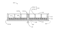
図1(斜視図)及び図2(側面図)は、本発明の第1実施形態(請求項1に対応)を示す図である。本実施形態は、連続I桁橋10(図17参照)におけるI桁30のうち、中間支点12近傍のI桁30に適用されている。I桁30は、上フランジ32、下フランジ34、ウェブ36、鉛直補剛材38から構成されている。鉛直補剛材38は、中間支点部鉛直補剛材38Aおよび一般部鉛直補剛材38Bからなる。ウェブ36の下部には、貫通孔36Aが複数個設けられ、該貫通孔36Aにウェブ挿通鉄筋40が挿通して配設されている。下フランジ34の上面には、ずれ止めである頭付きスタッド48が複数配設され、さらに、橋軸方向鉄筋42、橋軸直角方向鉄筋44および帯筋46が適宜配設されている。
FIG. 1 (perspective view) and FIG. 2 (side view) are views showing a first embodiment (corresponding to claim 1) of the present invention. This embodiment is applied to the
下フランジ34の上面、ウェブ36の下部、鉛直補剛材38の下部で囲まれる空間にはフレッシュコンクリートが打設されて、所定の配筋(ウェブ挿通鉄筋40、橋軸方向鉄筋42、橋軸直角方向鉄筋44および帯筋46)および頭付きスタッド48を全て含み、かつ、下フランジ34の上面、ウェブ36の下部および鉛直補剛材38の下部と一体化した、前記フレッシュコンクリートが硬化してなるコンクリート50が下フランジ34の上面に配設されている。これにより、下フランジ34やウェブ36の局部座屈およびI桁30全体の横座屈が防止されており、I桁30の耐荷力が格段に向上している。
Fresh concrete is placed in a space surrounded by the upper surface of the
次に、第1実施形態の施工方法について説明する。 Next, the construction method of the first embodiment will be described.
まず、図3に示すように、下フランジ34の上面にずれ止めである頭付きスタッド48を配設し、予めウェブ36に開けておいた貫通孔36Aにウェブ挿通鉄筋40を挿通する。さらに、図4に示すように、橋軸方向鉄筋42、橋軸直角方向鉄筋44、帯筋46の組み立ておよび配設を行なう。
First, as shown in FIG. 3, a headed
次に、フレッシュコンクリートの打設を行う。フレッシュコンクリートの打設では、型枠(ここでは図示せず)を設置して、下フランジ34の上面、ウェブ36の下部、鉛直補剛材38の下部で囲まれる空間に、フレッシュコンクリートを打設する。該フレッシュコンクリートが硬化してなるコンクリート50の高さは、下フランジ34の板厚や期待する曲げ耐力などにより異なるが、桁高3mのI桁橋の場合、300mm〜700mm程度とすることができる。ここで、図3に示すように、一般部鉛直補剛材38Bの下部にも予め貫通孔38Cを開けておけば、打設したフレッシュコンクリートが貫通孔38Cの中にも回り込み、一般部鉛直補剛材38Bとコンクリート50との一体性をさらに高めることができる。
Next, fresh concrete is placed. In placing fresh concrete, a formwork (not shown here) is installed, and fresh concrete is placed in a space surrounded by the upper surface of the
硬化したコンクリート50は、下フランジ34の上面、ウェブ36の下部、鉛直補剛材38の下部、ウェブ挿通鉄筋40の全体、橋軸方向鉄筋42の全体、橋軸直角方向鉄筋44の全体、帯筋46の全体、頭付きスタッド48の全体と一体化しており、合成構造を形成している。これにより、連続I桁橋10の中間支点12近傍のI桁30において、供用時に活荷重等により大きな負の曲げモーメントが生じて、ウェブ36下部から下フランジ34にかけての桁断面に大きな圧縮力が作用しても、下フランジ34やウェブ36が局部座屈したり、I桁30全体が横座屈したりすることが防止される。座屈が防止されることにより、I桁30は鋼材の塑性域の性能を十分に活用することができるようになる。さらに、I桁30は、コンクリート50と一体化した合成構造となっているので、鋼とコンクリートの合成断面として負の曲げモーメントに抵抗することができる。以上のことより、I桁30は、負の曲げモーメントに対する耐荷力が大幅に向上している。
The
なお、本実施形態の施工において、頭付きスタッド48の配設、鉄筋40、42、44、46の配設、フレッシュコンクリートの打設は、工場や現場ヤード等で、I桁30の架設前に行うことができる。また、I桁30を中間支点12上に架設した後に、現場で行ってもよい。
In the construction of the present embodiment, the headed
図5は、本発明の第2実施形態(請求項3に対応)を示す斜視図であり、図6は同じく側面図である。 FIG. 5 is a perspective view showing a second embodiment (corresponding to claim 3) of the present invention, and FIG. 6 is a side view of the same.
第2実施形態は、フレッシュコンクリートを2段階に分けて打設している点が第1実施形態と異なり、第1段階の一次フレッシュコンクリートの打設後に、I桁30を中間支点12上に架設し、架設後に第2段階の二次フレッシュコンクリートの打設を行なっており、コンクリート50が、一次フレッシュコンクリートが硬化してなる一次コンクリート50Aと、二次フレッシュコンクリートが硬化してなる二次コンクリート50Bとからなっている点が第1実施形態と異なる。頭付きスタッド48の配設、鉄筋40、42、44、46の配設は、第1実施形態と同様である。
The second embodiment is different from the first embodiment in that fresh concrete is placed in two stages, and the
次に、図5〜図11を用いて、第2実施形態の施工方法(請求項5に対応)について説明する。なお、図7〜図11は、施工途中の段階を示す図であり、図5、図6は、完成段階を示す図である。 Next, the construction method of the second embodiment (corresponding to claim 5) will be described with reference to FIGS. 7-11 is a figure which shows the stage in the middle of construction, and FIG. 5, FIG. 6 is a figure which shows a completion stage.
この第2実施形態の施工は、I桁30を架設する前までに工場や現場ヤード等で行う第1施工段階(図7〜図9)と、I桁30を架設してから完成までの第2施工段階(図10、図11、図5、図6)に分けられるので、第1施工段階から説明する。
The construction of the second embodiment includes the first construction stage (FIGS. 7 to 9) performed in the factory, the yard, etc. before the I-
第1施工段階では、まず、図7に示すように、下フランジ34の上面にずれ止めである頭付きスタッド48を配設し、予めウェブ36に開けておいた貫通孔36Aにウェブ挿通鉄筋40を挿通する。さらに、図8に示すように、一次コンクリート50Aに全部あるいは一部が埋設される下段の橋軸方向鉄筋42および帯筋46の組み立ておよび配設を行なう。
In the first construction stage, first, as shown in FIG. 7, a headed
次に、第1段階の一次フレッシュコンクリートの打設を行う。第1段階の一次フレッシュコンクリートの打設では、型枠(ここでは図示せず)を設置して、下フランジ34の上面、ウェブ36の下部、鉛直補剛材38の下部で囲まれる空間に、ウェブ36の下部を挿通して配設されたウェブ挿通鉄筋40が覆われる高さまで一次フレッシュコンクリートを打設する。一次フレッシュコンクリートの打設高さは、下フランジ34の板厚や施工性などを勘案し、70〜150mm程度とすることができる。ここで、図7および図8に示すように、一般部鉛直補剛材38Bの下部にも予め貫通孔38Cを開けておけば、打設した一次フレッシュコンクリートが貫通孔38Cの中にも回り込み、一般部鉛直補剛材38Bと、一次フレッシュコンクリートが硬化してなる一次コンクリート50Aとの一体性をさらに高めることができる。
Next, primary fresh concrete is placed in the first stage. In the placement of primary fresh concrete in the first stage, a formwork (not shown here) is installed, and in a space surrounded by the upper surface of the
図9に、一次フレッシュコンクリートが硬化した後の第1施工段階の最終段階のI桁30の状況を示す。一次フレッシュコンクリートが硬化してなる一次コンクリート50Aは、下フランジ34、ウェブ36の下部、鉛直補剛材38の下部、ウェブ挿通鉄筋40の全体、下段の橋軸方向鉄筋42の全体、帯筋46の下部、頭付きスタッド48の下部と一体化しており、合成構造を形成している。
FIG. 9 shows the state of the I-
なお、前述したように、図7〜図9に示す第1施工段階は、工場や現場ヤード等で、I桁30の架設前に行う。
In addition, as mentioned above, the 1st construction stage shown in FIGS. 7-9 is performed before construction of the
次に、第2施工段階について説明する。 Next, the second construction stage will be described.
第2施工段階では、まず、一次フレッシュコンクリートが硬化した後の第1施工段階の最終段階(図9)のI桁30を、図10に示すように、中間支点12上に架設する。第1施工段階でコンクリートと鋼の合成構造が構築されており、この合成構造が、I桁30の架設時における、下フランジ34およびウェブ36の局部座屈ならびにI桁30全体の横座屈の防止に寄与するため、安定した架設が可能となる。また、一次フレッシュコンクリートは、ウェブ挿通鉄筋40が覆われる高さまで打設すればよいので、打設高さを小さくすることができ、I桁30の重量の増加を抑えることができるため、一次フレッシュコンクリートが硬化した後のI桁30の運搬および架設も容易となり、工期も短縮することができる。
In the second construction stage, first, the I-
中間支点12上にI桁30を架設した後、図11に示すように、上段の橋軸方向鉄筋42および橋軸直角方向鉄筋44を適宜追加し、型枠(ここでは図示せず)を設置して、一次コンクリート50Aの上面、ウェブ36の下部、鉛直補剛材38の下部で囲まれる空間に二次フレッシュコンクリートを打設する。二次フレッシュコンクリートの打設高さは、下フランジ34の板厚、期待する曲げ耐力などにより異なるが、桁高3mのI桁橋の場合、200〜600mm程度とすることができる。
After the I-
二次フレッシュコンクリートが硬化して二次コンクリート50Bになると、図5及び図6に示すように、I桁30と一次コンクリート50Aおよび二次コンクリート50Bが一体化した合成構造になる。これにより、連続I桁橋10の中間支点12近傍において、供用時に活荷重等により大きな負の曲げモーメントが生じて、ウェブ36下部から下フランジ34にかけての桁断面に大きな圧縮力が作用しても、下フランジ34やウェブ36が局部座屈したり、I桁30全体が横座屈したりすることが防止される。座屈が防止されることにより、I桁30は鋼材の塑性域の性能を十分に活用することができるようになる。さらに、I桁30は、一次コンクリート50Aおよび二次コンクリート50Bと一体化した合成構造となっているので、鋼とコンクリートの合成断面として負の曲げモーメントに抵抗することができる。以上のことより、I桁30は、負の曲げモーメントに対する耐荷力が大幅に向上している。
When the secondary fresh concrete is hardened to become the
また、第1実施形態、第2実施形態において、鉄筋40、42、44、46および頭付きスタッド48は、全て、第1実施形態ではコンクリート50(第2実施形態では50A、50B)内に埋設されており、特許文献1の図6の場合とは異なり鋼部材が大気中に露出していないので、鋼部材(鉄筋40、42、44、46および頭付きスタッド48)の腐食は抑制される。
In the first and second embodiments, the reinforcing
ここで、負の曲げモーメントを受ける中間支点12近傍のI桁30の構造における塑性応力状態での断面の応力分布の概念図を図12に示す。ここでは、床版60内の橋軸方向鉄筋60A、I桁30、コンクリート50(または50A、50B)を考慮して塑性応力状態における力の釣り合いを考え、塑性中立軸を算出している。なお、床版60のコンクリートは引張域となり、ひび割れを生じるため、ここでは考慮していない。塑性中立軸より上の領域は引張応力が生じている引張域、塑性中立軸より下の領域は圧縮応力が生じている圧縮域となる。図12において、hcは第1実施形態ではコンクリート50の高さを示し、第2実施形態では一次コンクリート50Aと二次コンクリート50Bの合計の高さを示す。Dcpは第1実施形態ではコンクリート50の下面から塑性中立軸までの距離を示し、第2実施形態では一次コンクリート50Aの下面から塑性中立軸までの距離を示す。
Here, a conceptual diagram of the stress distribution of the cross section in the plastic stress state in the structure of the
塑性応力状態での断面の応力分布を考慮して、第1実施形態では配設するコンクリート50の高さ(第2実施形態では一次コンクリート50Aと二次コンクリート50Bの合計の高さ)を塑性中立軸以下の圧縮域内に制限(hc≦Dcp)することにより、第1実施形態ではコンクリート50(第2実施形態では一次コンクリート50Aと二次コンクリート50B)に作用する応力を常に圧縮応力とすることができる。この場合、第1実施形態ではコンクリート50(第2実施形態では一次コンクリート50Aと二次コンクリート50B)にはひび割れが発生せず、全塑性曲げモーメントに達するまで、第1実施形態ではコンクリート50(第2実施形態では第一コンクリート50Aと第二コンクリート50B)の性能をフルに活用することができる。また、第1実施形態では配設するコンクリート50の高さ(第2実施形態では一次コンクリート50Aと二次コンクリート50Bの合計の高さ)を塑性中立軸以下の圧縮域内に制限(hc≦Dcp)することにより、打設するフレッシュコンクリートの量も少なくなり、重量増加が抑制される。
In consideration of the stress distribution of the cross section in the plastic stress state, the height of the concrete 50 to be arranged in the first embodiment (the total height of the
なお、第1実施形態および第2実施形態のどちらにおいても、概ね平らで安定した下フランジ34上に鉄筋を設置すればよいため、鉄筋の配設作業およびその施工管理は容易である。
In both the first embodiment and the second embodiment, the reinforcing bars need only be installed on the substantially flat and stable
また、第1実施形態、第2実施形態において、ずれ止めとして頭付きスタッド48を用いたが、ずれ止めはこれに限られず、頭付きスタッド48に替えて、あるいは頭付きスタッド48とともに、例えば図13に示すような板部材52をずれ止めとして用いてもよい。また、例えば、形鋼をずれ止めに用いてもよいし、形鋼や鉄筋で形成されたトラス形状のずれ止めを用いてもよい。ただし、せん断耐力、じん性、断面の合成効果などを考慮した上で、適切なタイプのものを選定する必要がある。
In the first embodiment and the second embodiment, the headed
図14および図15は、第1実施形態または第2実施形態を連続I桁橋10に適用した場合で、下フランジ34の上面に配設されるコンクリート50(第1実施形態の場合)またはコンクリート50A、50B(第2実施形態の場合)の橋軸方向の配置位置を模式的に示す側面図である。図14および図15において、符号14は、端支点を示す。
FIGS. 14 and 15 show concrete 50 (in the case of the first embodiment) or concrete disposed on the upper surface of the
本発明の実施形態においては、コンクリート50(第1実施形態の場合)またはコンクリート50A、50B(第2実施形態の場合)は、中間支点12近傍の負の曲げモーメントが作用する領域(以下、負曲げ域と記す)に配置する。図14に示すように、コンクリート50(第1実施形態の場合)またはコンクリート50A、50B(第2実施形態の場合)を負曲げ域の全域にわたり配置してもよいし、図15に示すように、負の曲げモーメントが特に大きい領域のみに配置してもよい。コンクリート50(第1実施形態の場合)またはコンクリート50A、50B(第2実施形態の場合)の橋軸方向の配置位置は、断面に作用する負の曲げモーメントの大きさや、I桁に座屈が生じるときの曲げモーメントの大きさ等を勘案して決定すればよい。このように、コンクリート50(第1実施形態の場合)またはコンクリート50A、50B(第2実施形態の場合)を配置する位置を、所定の負曲げ域に限定することにより、連続I桁橋10の重量増加を抑えつつ、中間支点12近傍のI桁30の下フランジ34およびウェブ36下部の局部座屈ならびにI桁30全体の横座屈を効果的に防止することができる。
In the embodiment of the present invention, the concrete 50 (in the case of the first embodiment) or the concrete 50A, 50B (in the case of the second embodiment) is a region where a negative bending moment in the vicinity of the intermediate fulcrum 12 acts (hereinafter referred to as negative). Place it in the bending area. As shown in FIG. 14, the concrete 50 (in the case of the first embodiment) or the concrete 50A, 50B (in the case of the second embodiment) may be arranged over the entire area of the negative bending region, as shown in FIG. Further, it may be arranged only in a region where the negative bending moment is particularly large. The arrangement position of the concrete 50 (in the case of the first embodiment) or the concrete 50A, 50B (in the case of the second embodiment) in the direction of the bridge axis is such that the magnitude of the negative bending moment acting on the cross section and the buckling of the I-girder. It may be determined in consideration of the magnitude of the bending moment when it occurs. Thus, by limiting the position where the concrete 50 (in the case of the first embodiment) or the concrete 50A, 50B (in the case of the second embodiment) is arranged to a predetermined negative bending region, the continuous
図16は、第2実施形態を連続I桁橋(2主I桁橋)20に適用した場合で、中間支点12近傍を橋軸直角方向の面で切断した断面を斜め上方から見た斜視図である。I桁30のウェブ36下部の両側において、下フランジ34の上面に、コンクリート50A、50Bおよびウェブ挿通鉄筋40等が配設されており、I桁30のウェブ36下部は両側からコンクリート50A、50Bおよびウェブ挿通鉄筋40等で拘束されている。平行に並んだ2つのI桁30の上には、床版80が配設されている。
FIG. 16 is a perspective view in which the second embodiment is applied to a continuous I girder bridge (two main I girder bridges) 20 and a cross section obtained by cutting the vicinity of the intermediate fulcrum 12 with a plane perpendicular to the bridge axis is viewed obliquely from above. It is.
なお、以上説明してきた実施形態では、I桁30の上に設置する床版80の施工については記述していないが、架設ステップや施工順序などを勘案して適切に施工を行う必要がある。床版80の施工順序についての工夫としては、ブロック施工の順序についての工夫(中間支点ブロックの後打ちなど)をしたり、I桁30の下フランジ34上にフレッシュコンクリートを打設して配設するコンクリート50(第1実施形態の場合)またはコンクリート50A、50B(第2実施形態の場合)との施工順序についての工夫をしたりすることなどが考えられる。
In the embodiment described above, the construction of the
10…連続I桁橋
12…中間支点
14…端支点
20…連続I桁橋(2主I桁橋)
30…I桁
32…上フランジ
34…下フランジ
36…ウェブ
36A…貫通孔
38…鉛直補剛材
38A…中間支点部鉛直補剛材
38B…一般部鉛直補剛材
40…ウェブ挿通鉄筋
42…橋軸方向鉄筋
44…橋軸直角方向鉄筋
46…帯筋
48…頭付きスタッド
50…コンクリート
50A…一次コンクリート
50B…二次コンクリート
52…板部材
60、80…床版
60A…床版60内の橋軸方向鉄筋
10 ... Continuous I girder bridge 12 ...
30 ... I-
Claims (6)
Priority Applications (1)
| Application Number | Priority Date | Filing Date | Title |
|---|---|---|---|
| JP2007261240A JP4967972B2 (en) | 2007-10-04 | 2007-10-04 | Continuous I-girder bridge, I-girder structure near its intermediate fulcrum and its construction method |
Applications Claiming Priority (1)
| Application Number | Priority Date | Filing Date | Title |
|---|---|---|---|
| JP2007261240A JP4967972B2 (en) | 2007-10-04 | 2007-10-04 | Continuous I-girder bridge, I-girder structure near its intermediate fulcrum and its construction method |
Publications (2)
| Publication Number | Publication Date |
|---|---|
| JP2009091744A JP2009091744A (en) | 2009-04-30 |
| JP4967972B2 true JP4967972B2 (en) | 2012-07-04 |
Family
ID=40664002
Family Applications (1)
| Application Number | Title | Priority Date | Filing Date |
|---|---|---|---|
| JP2007261240A Active JP4967972B2 (en) | 2007-10-04 | 2007-10-04 | Continuous I-girder bridge, I-girder structure near its intermediate fulcrum and its construction method |
Country Status (1)
| Country | Link |
|---|---|
| JP (1) | JP4967972B2 (en) |
Family Cites Families (8)
| Publication number | Priority date | Publication date | Assignee | Title |
|---|---|---|---|---|
| JPH1181240A (en) * | 1997-09-11 | 1999-03-26 | Ishikawajima Harima Heavy Ind Co Ltd | Beam structure for continuous beam bridge |
| JPH11148110A (en) * | 1997-11-14 | 1999-06-02 | Ishikawajima Harima Heavy Ind Co Ltd | Continuous girder bridge |
| JP3660826B2 (en) * | 1999-05-12 | 2005-06-15 | 新日本製鐵株式会社 | Rigid structure of upper and lower composite members |
| JP2002266319A (en) * | 2001-03-08 | 2002-09-18 | Topy Ind Ltd | Repair and reinforcing structure and method of existing steel girder |
| JP3830767B2 (en) * | 2001-03-12 | 2006-10-11 | トピー工業株式会社 | Continuous girder for bridge |
| JP2004176344A (en) * | 2002-11-26 | 2004-06-24 | Topy Ind Ltd | Box girder bridge |
| JP4040533B2 (en) * | 2003-06-04 | 2008-01-30 | トピー工業株式会社 | Continuous girder structure of bridge and continuous girder stiffening method |
| JP4492422B2 (en) * | 2005-04-18 | 2010-06-30 | Jfeエンジニアリング株式会社 | Structure near the intermediate fulcrum of continuous I-girder bridge |
-
2007
- 2007-10-04 JP JP2007261240A patent/JP4967972B2/en active Active
Also Published As
| Publication number | Publication date |
|---|---|
| JP2009091744A (en) | 2009-04-30 |
Similar Documents
| Publication | Publication Date | Title |
|---|---|---|
| AU2015246120B2 (en) | Open web composite shear connector construction | |
| US6807789B1 (en) | Steel-concrete composite beam using asymmetric section steel beam | |
| JP2007023714A (en) | Composite floor slab using shape steel, composite floor slab bridge or composite girder bridge and its construction method | |
| JP2008063803A (en) | Composite floor slab formed of shape steel with inner rib, composite floor slab bridge, or composite girder bridge | |
| WO2010021428A1 (en) | Opening steel composite girder and method for manufacturing the same | |
| JPWO2018159381A1 (en) | Steel concrete beam and construction method of steel concrete beam | |
| JP5184836B2 (en) | Construction method of synthetic steel slab girder bridge | |
| JP3830767B2 (en) | Continuous girder for bridge | |
| JP5029271B2 (en) | I-girder structure near the continuous I-girder bridge and its intermediate fulcrum | |
| JP4508293B2 (en) | Structure near the intermediate fulcrum of continuous I-girder bridge | |
| JP4492422B2 (en) | Structure near the intermediate fulcrum of continuous I-girder bridge | |
| JP2008088634A (en) | Composite steel-concrete floor slab | |
| JP4644146B2 (en) | PC box girder bridge | |
| KR101426155B1 (en) | The hybrid rahmen structure which can add prestress on steel girder of horizontal member by gap difference of connection face between vertical member and steel girder of horizontal member | |
| KR20130090709A (en) | Construction method for corrugated steel plate web-psc composite beam | |
| KR102396444B1 (en) | Composite structure of bridge deck and open box girder | |
| KR101698807B1 (en) | Manufacturing method of the psc girder using the corrugated steel plate and the psc girder manufactured thereby | |
| JP4967972B2 (en) | Continuous I-girder bridge, I-girder structure near its intermediate fulcrum and its construction method | |
| JP4293696B2 (en) | Construction method of composite floor slab bridge | |
| JP4654138B2 (en) | Joint structure of steel main girder and substructure | |
| KR101957237B1 (en) | Composite rigid-frame bridge with steel girder for having prestress-induced coner part, and construction method for he same | |
| JP5105016B2 (en) | I-girder structure near the continuous I-girder bridge and its intermediate fulcrum | |
| JP7185617B2 (en) | steel formwork | |
| JP3996043B2 (en) | Joint structure of bridge corrugated steel web composite girder | |
| KR20200137334A (en) | Advanced Interlocking Girder adapt to Load Factor Resistance Design Method |
Legal Events
| Date | Code | Title | Description |
|---|---|---|---|
| A621 | Written request for application examination |
Free format text: JAPANESE INTERMEDIATE CODE: A621 Effective date: 20100303 |
|
| A977 | Report on retrieval |
Free format text: JAPANESE INTERMEDIATE CODE: A971007 Effective date: 20110726 |
|
| TRDD | Decision of grant or rejection written | ||
| A01 | Written decision to grant a patent or to grant a registration (utility model) |
Free format text: JAPANESE INTERMEDIATE CODE: A01 Effective date: 20120306 |
|
| A01 | Written decision to grant a patent or to grant a registration (utility model) |
Free format text: JAPANESE INTERMEDIATE CODE: A01 |
|
| A61 | First payment of annual fees (during grant procedure) |
Free format text: JAPANESE INTERMEDIATE CODE: A61 Effective date: 20120319 |
|
| FPAY | Renewal fee payment (event date is renewal date of database) |
Free format text: PAYMENT UNTIL: 20150413 Year of fee payment: 3 |
|
| R150 | Certificate of patent or registration of utility model |
Ref document number: 4967972 Country of ref document: JP Free format text: JAPANESE INTERMEDIATE CODE: R150 Free format text: JAPANESE INTERMEDIATE CODE: R150 |
|
| S531 | Written request for registration of change of domicile |
Free format text: JAPANESE INTERMEDIATE CODE: R313531 |
|
| R370 | Written measure of declining of transfer procedure |
Free format text: JAPANESE INTERMEDIATE CODE: R370 |
|
| R370 | Written measure of declining of transfer procedure |
Free format text: JAPANESE INTERMEDIATE CODE: R370 |
|
| S531 | Written request for registration of change of domicile |
Free format text: JAPANESE INTERMEDIATE CODE: R313531 |
|
| R371 | Transfer withdrawn |
Free format text: JAPANESE INTERMEDIATE CODE: R371 |
|
| S531 | Written request for registration of change of domicile |
Free format text: JAPANESE INTERMEDIATE CODE: R313531 |
|
| R350 | Written notification of registration of transfer |
Free format text: JAPANESE INTERMEDIATE CODE: R350 |