JP4966575B2 - Biological heating device - Google Patents
Biological heating device Download PDFInfo
- Publication number
- JP4966575B2 JP4966575B2 JP2006096064A JP2006096064A JP4966575B2 JP 4966575 B2 JP4966575 B2 JP 4966575B2 JP 2006096064 A JP2006096064 A JP 2006096064A JP 2006096064 A JP2006096064 A JP 2006096064A JP 4966575 B2 JP4966575 B2 JP 4966575B2
- Authority
- JP
- Japan
- Prior art keywords
- solenoid coil
- living body
- magnetic
- magnetic flux
- warming device
- Prior art date
- Legal status (The legal status is an assumption and is not a legal conclusion. Google has not performed a legal analysis and makes no representation as to the accuracy of the status listed.)
- Active
Links
Images


Classifications
-
- A—HUMAN NECESSITIES
- A61—MEDICAL OR VETERINARY SCIENCE; HYGIENE
- A61F—FILTERS IMPLANTABLE INTO BLOOD VESSELS; PROSTHESES; DEVICES PROVIDING PATENCY TO, OR PREVENTING COLLAPSING OF, TUBULAR STRUCTURES OF THE BODY, e.g. STENTS; ORTHOPAEDIC, NURSING OR CONTRACEPTIVE DEVICES; FOMENTATION; TREATMENT OR PROTECTION OF EYES OR EARS; BANDAGES, DRESSINGS OR ABSORBENT PADS; FIRST-AID KITS
- A61F7/00—Heating or cooling appliances for medical or therapeutic treatment of the human body
- A61F7/0053—Cabins, rooms, chairs or units for treatment with a hot or cold circulating fluid
-
- A—HUMAN NECESSITIES
- A61—MEDICAL OR VETERINARY SCIENCE; HYGIENE
- A61N—ELECTROTHERAPY; MAGNETOTHERAPY; RADIATION THERAPY; ULTRASOUND THERAPY
- A61N1/00—Electrotherapy; Circuits therefor
- A61N1/40—Applying electric fields by inductive or capacitive coupling ; Applying radio-frequency signals
- A61N1/403—Applying electric fields by inductive or capacitive coupling ; Applying radio-frequency signals for thermotherapy, e.g. hyperthermia
Description
この発明は、癌の治療などのために生体の局部を加温するのに適した生体加温装置に関し、詳しくは、ソレノイドコイルを用いて磁束を生じさせ、この磁束を生体に照射することにより、生体内部の患部等を加温する生体加温装置に関する。
この生体加温装置の利用は、癌細胞を選択的に壊死させるために患部を集中的に加温する局部温熱療法(ハイパーサーミヤ法)に適しており、特に、微粒子の感磁発熱体を生体内に配し、生体外から交番磁界を印加して発熱させるのに、好適なものである。
The present invention relates to a living body heating apparatus suitable for heating a local part of a living body for cancer treatment or the like, and more specifically, by generating a magnetic flux using a solenoid coil and irradiating the living body with this magnetic flux. The present invention relates to a living body heating apparatus that heats an affected part or the like inside a living body.
The use of this biological warming device is suitable for local thermotherapy (hyperthermia method) in which the affected area is intensively heated to selectively necrotize cancer cells. It is suitable for placing in a living body and generating heat by applying an alternating magnetic field from outside the living body.
癌治療等のために生体内奥部の小領域を集中的に加温できるようになった生体加温装置として、比透磁率を高位に限定した鉄系酸化物の微粒子を主成分とする感磁発熱体を生体内部に配置し、交番磁界発生装置にて生体を通る磁束を形成する、というものが知られている(例えば特許文献1参照)。この交番磁界発生装置の構成例として、生体を囲んで配置できるソレノイドコイルに交流を通電することにより縦断的な磁束すなわち生体を主として身長方向に貫く磁束を生じるものと、生体を挟んで配置できる磁極対により横断的な磁束を生じるものとがある。 As a living body warming device that can intensively heat a small area in the back of the body for cancer treatment, etc., it feels mainly composed of fine particles of iron-based oxide with a high relative permeability. It is known that a magnetic heating element is disposed inside a living body and a magnetic flux passing through the living body is formed by an alternating magnetic field generator (see, for example, Patent Document 1). As an example of the configuration of this alternating magnetic field generator, a longitudinal magnetic flux, that is, a magnetic flux that penetrates the living body mainly in the height direction by energizing a solenoid coil that can be placed surrounding the living body, and a magnetic pole that can be placed across the living body. Some pairs generate transverse magnetic flux.
また、高周波電界によって生体の表層部が誘電加熱されるのを緩和・防止するために、生体を遊挿しうるソレノイドコイルに筒状の高誘電体を内装した磁束照射装置が知られている(例えば特許文献2参照)。この磁束照射装置は、ソレノイドコイルに高周波通電を行うことにより、縦断的な磁束を生じ、それを高誘電体の中空部内に配置された生体のほぼ全体に照射するようになっている。そのソレノイドコイルの横断面(ソレノイド径方向の断面すなわちソレノイド軸方向に直交する断面)形状は、ほぼ円形であった。 In addition, in order to mitigate / prevent the surface heating of the living body due to dielectric heating due to a high-frequency electric field, a magnetic flux irradiation device in which a cylindrical high dielectric is housed in a solenoid coil into which a living body can be loosely inserted is known (for example, Patent Document 2). This magnetic flux irradiating device generates a longitudinal magnetic flux by applying a high-frequency current to a solenoid coil, and irradiates almost the entire living body disposed in the hollow portion of the high dielectric. The cross section of the solenoid coil (the cross section in the solenoid radial direction, that is, the cross section perpendicular to the solenoid axial direction) was substantially circular.
さらに、人体等の被射体の局所に対して一方向から高密度の磁束を照射するために、磁束発生部の一端(作用端)側から高密度の磁束が発射されるようにした、単一作用磁極タイプの磁束照射装置もある(例えば特許文献3,4参照)。これらの磁束照射装置は、高周波通電により磁束を生じる小形ソレノイドコイルに、磁束強化およびソレノイド軸方向磁束到達距離延伸のため棒状の磁心を嵌挿したものである。ソレノイド軸方向磁束到達距離の更なる延伸のためソレノイドコイルの外側に且つ作用端側の短区間に補強巻線を巻成したものや(例えば特許文献3参照)、磁心の昇温防止等のため磁心の作用端側よりも非作用端側を太くしたり冷媒の流路を磁心に形成したものも知られている(例えば特許文献4参照)。 Furthermore, in order to irradiate a high-density magnetic flux from one direction to the local subject such as the human body, a high-density magnetic flux is emitted from one end (working end) side of the magnetic flux generation unit. There is also a single-action magnetic pole type magnetic flux irradiation device (see, for example, Patent Documents 3 and 4). In these magnetic flux irradiating devices, a rod-shaped magnetic core is inserted into a small solenoid coil that generates a magnetic flux by high-frequency energization for magnetic flux enhancement and solenoid axial direction magnetic flux reaching distance extension. In order to further extend the reach distance of the magnetic flux in the axial direction of the solenoid, a reinforcing winding is wound outside the solenoid coil and in a short section on the working end side (for example, refer to Patent Document 3), for prevention of temperature rise of the magnetic core, etc. Also known are those in which the non-acting end side is made thicker than the working end side of the magnetic core, or the flow path of the refrigerant is formed in the magnetic core (see, for example, Patent Document 4).
[特許文献5] 特願2005−057437号 [Patent Document 5] Japanese Patent Application No. 2005-057437
上述したような従来の生体加温装置では、生体全体に縦断的な磁束を照射する生体包囲ソレノイドタイプの場合、磁束が生体の深奥部まで到達することや、磁束が概ね平行な磁力線群で構成されることから、生体のほぼ全体において磁束に沿った方向の磁束密度の減少勾配が小さくなるので、不所望なホットスポットの発生が少ないこと等の利点があるが、患部の感磁発熱体など所望部位に磁束を集中させるのが難しい、という不満もある。 In the conventional living body warming device as described above, in the case of a living body surrounding solenoid type that irradiates a longitudinal magnetic flux on the entire living body, the magnetic flux reaches a deep part of the living body, or is composed of a group of magnetic force lines in which the magnetic flux is substantially parallel. Therefore, since the decreasing gradient of the magnetic flux density in the direction along the magnetic flux becomes small in almost the whole living body, there are advantages such as less occurrence of undesired hot spots, but the magnetosensitive heating element of the affected part, etc. There is also a complaint that it is difficult to concentrate the magnetic flux at the desired site.
これに対して、局所的な磁束を生じる単一作用磁極タイプの場合、作用端近傍にて磁束が集中しているので、生体の体表面近傍の部位であれば十分に加温することができる等の利点がある。しかし、作用端から遠ざかるほど磁束が広がって行くので磁束に沿った方向の磁束密度の減少勾配は急峻であることから、深部を加温しようとしてコイル電流を増加させると、体表面の磁束密度は過大とならざるを得ず、体表面の誘導電流が増加して、正常細胞まで不所望に加熱されてしまう、という不満がある。 On the other hand, in the case of a single action magnetic pole type that generates a local magnetic flux, since the magnetic flux is concentrated near the action end, it can be sufficiently heated if it is a part near the body surface of the living body. There are advantages such as. However, since the magnetic flux spreads away from the working end, the decreasing gradient of the magnetic flux density in the direction along the magnetic flux is steep, so when increasing the coil current to warm the deep part, the magnetic flux density on the body surface becomes There is a dissatisfaction that the induced current on the body surface is increased and the normal cells are undesirably heated up.
また、横断的な磁束を生じる磁極対タイプの場合、両者の中間の特性が示され、磁束の広がり方も磁束密度の減少勾配も中程度となる。このため、利点も不満点も中間的なものとなる。
しかしながら、生体加温装置を用いた局部温熱療法の効果を高めるには、患部のところでは磁束が生体の内奥部まで高密度のまま到達するとともに、正常な体表面では磁束密度が低くなる、という特性の強化が求められる。
そして、生体包囲型でもソレノイドコイルに遊挿可能な磁性体を設けることにより、磁束の集中と分散を生体内部で自在かつ明瞭に行えるようになった(特許文献5参照)。
Further, in the case of a magnetic pole pair type that generates a transverse magnetic flux, a characteristic intermediate between the two is shown, and the spreading direction of the magnetic flux and the decreasing gradient of the magnetic flux density are medium. For this reason, both advantages and dissatisfaction are intermediate.
However, in order to increase the effect of local thermotherapy using a living body warming device, the magnetic flux reaches the inner part of the living body with a high density at the affected part, and the magnetic flux density is lowered on the normal body surface. Strengthening the characteristics is required.
By providing a magnetic body that can be loosely inserted into the solenoid coil even in the living body surrounding type, the magnetic flux can be concentrated and dispersed freely and clearly inside the living body (see Patent Document 5).
因みに、上記生体加温装置でも、可動寝台などの生体保持具を遊挿しうるソレノイドコイルは、当然のことのように円筒状で具現化されており、その横断面形状はほぼ円形である。そして、患者等の生体が生体保持具上に横たわると生体がソレノイド横断面形状の円の概ね中心に位置するようになっている。
一方、加温するべき患部は、多くの場合、生体の中心部より外側に偏倚して位置している。そして、ソレノイドコイルの巻き線が作る磁束は、その高密度領域が巻き線寄りの環状領域に位置しているから、コイル径が大きく周長の長い生体包囲ソレノイドタイプの場合、ソレノイドコイルの磁束のうち患部の加温に寄与するのは実質的にはソレノイドコイル全周のうちの患部に近い一角に限られることとなり、患部から遠い方角の部分は、患部の加温にほとんど役立っておらず、この部分のコイルインピーダンスは、加温という観点では高周波電源に負荷をもたらすだけの無益な存在となっている。
Incidentally, in the living body heating apparatus, the solenoid coil into which the living body holder such as a movable bed can be loosely inserted is naturally embodied in a cylindrical shape, and its cross-sectional shape is substantially circular. When a living body such as a patient lies on the living body holder, the living body is positioned approximately at the center of a circle having a solenoid cross-sectional shape.
On the other hand, the affected area to be heated is often biased to the outside of the center of the living body. The magnetic flux generated by the winding of the solenoid coil is located in an annular region close to the winding. Therefore, in the case of a biological surrounding solenoid type with a large coil diameter and a long circumference, the magnetic flux of the solenoid coil Of these, the part that contributes to the warming of the affected area is practically limited to only one corner of the entire solenoid coil that is close to the affected area, and the part of the direction far from the affected area hardly contributes to the warming of the affected area. The coil impedance at this portion is useless enough to bring a load to the high frequency power supply from the viewpoint of heating.
かといって、ソレノイド横断面において患部から遠い方角の部分も、コイルに電流を流す必要上、ソレノイドコイルから除外する訳にはいかない。
しかしながら、コイルインピーダンスが大きいと、所要のコイル電流を確保するのに高い電圧をソレノイドコイルに印加しなければならないので、その分だけ出力の大きな高周波電源が必要になってコストが嵩むうえ、安全確保のための絶縁対策などにも高品質の部材等が必要になって更にコストが嵩む。
そこで、ソレノイドコイル内の患部に近い一角に所期の密度の磁束を発生可能であってコイルインピーダンスの小さい生体包囲ソレノイドタイプ生体加温装置を実現することが第1技術課題となる。
However, it is impossible to exclude a portion of the solenoid cross section far from the affected part from the solenoid coil because a current needs to flow through the coil.
However, if the coil impedance is large, a high voltage must be applied to the solenoid coil to ensure the required coil current, so a high-frequency power supply with a large output is required, which increases costs and ensures safety. In addition, high quality members are required for insulation measures, and the cost is further increased.
Therefore, it is a first technical problem to realize a living body surrounding solenoid type living body warming device that can generate a magnetic flux having a desired density in a corner near the affected part in the solenoid coil and has a small coil impedance.
また、加温するべき患部の大多数が生体の中心部より外側に偏倚して位置しているといっても、ソレノイドコイルの巻き線に近接するほど患部位置が偏倚している訳ではないので、磁束到達距離をソレノイド径方向に延伸させることも重要である。ソレノイド軸方向の磁束到達距離は、フェライト等の強磁性材料からなる磁性体をソレノイドコイルに挿入することで、延伸させることが可能であるが、ソレノイド径方向の磁束到達距離を延伸させるためには、ソレノイドコイルの形状の仕様の変更以外では、コイル電流を増加させることが必要である。 In addition, even if the majority of affected areas to be heated are biased to the outside of the center of the living body, the position of the affected area is not biased as it is closer to the winding of the solenoid coil. It is also important to extend the magnetic flux reach distance in the solenoid radial direction. The magnetic flux arrival distance in the solenoid axial direction can be extended by inserting a magnetic material made of a ferromagnetic material such as ferrite into the solenoid coil. However, in order to extend the magnetic flux arrival distance in the solenoid radial direction, Other than changing the specification of the solenoid coil shape, it is necessary to increase the coil current.
しかしながら、コイル電流の増加には一般にソレノイド印加電圧の上昇を伴うため、上述のように電源規模や安全確保の負担が重い。一方、生体包囲ソレノイドタイプの生体加温装置を使用する場合であっても、患部がソレノイドコイルの全長に及ぶことはなく、ソレノイド径方向の磁束到達距離の延伸が求められるのはソレノイド軸方向の一部分だけである。
そこで、上記一部分に係るソレノイドコイルの巻き線から離れた中心部寄りの部位に所期の密度の磁束を発生することの可能な生体包囲ソレノイドタイプ生体加温装置を実現することが第2技術課題となる。
However, since an increase in coil current generally accompanies an increase in solenoid applied voltage, the burden on power supply scale and safety is heavy as described above. On the other hand, even when using a living body surrounding solenoid type living body warming device, the affected part does not reach the entire length of the solenoid coil, and the extension of the magnetic flux arrival distance in the solenoid radial direction is required. It is only a part.
Accordingly, it is a second technical problem to realize a living body surrounding solenoid type living body warming device capable of generating a magnetic flux having a desired density at a portion near the center away from the winding of the solenoid coil according to the part. It becomes.
本発明の生体加温装置(請求項1)は、このような第1,第2技術課題を共に解決するために創案されたものであり、生体を遊挿しうる大きさの筒状ソレノイドコイルと、これに給電するための高周波電源と、前記ソレノイドコイルに遊挿しうる可動寝台などの生体保持具とを備えた生体加温装置において、前記ソレノイドコイルはその横断面に係る輪郭の形状が該輪郭の周方向における過半区間では円弧状であって残りの区間では直線状であり、更に、前記ソレノイドコイルに比べて長さが短く且つ捲回密度が密なコイルであって前記の又は別設の高周波電源から給電される副ソレノイドコイルが前記ソレノイドコイルに内挿されていることを特徴とする。 The living body warming device of the present invention (Claim 1) has been devised to solve both the first and second technical problems, and includes a cylindrical solenoid coil having a size capable of loosely inserting a living body. In the living body warming device including a high frequency power source for supplying power to the living body and a living body holder such as a movable bed that can be loosely inserted into the solenoid coil, the solenoid coil has a contour shape related to a transverse section thereof. The arc in the majority section in the circumferential direction and the straight section in the remaining section, and the coil is shorter in length and denser in winding density than the solenoid coil. A sub-solenoid coil fed from a high-frequency power source is inserted into the solenoid coil.
また、本発明の生体加温装置(請求項2)は、上記の請求項1記載の生体加温装置から、第1技術課題を解決する要件を抽出したものである。具体的には、生体を遊挿しうる大きさの筒状ソレノイドコイルと、これに給電するための高周波電源と、前記ソレノイドコイルに遊挿しうる可動寝台などの生体保持具とを備えた生体加温装置において、前記ソレノイドコイルはその横断面に係る輪郭の形状が該輪郭の周方向における過半区間では円弧状であって残りの区間では直線状である(本明細書では以下、この横断面形状を横断面D字形と呼ぶ)ことを特徴とする。 Moreover, the living body warming device (claim 2) of the present invention is obtained by extracting requirements for solving the first technical problem from the living body warming device according to claim 1 described above. Specifically, a living body heating provided with a cylindrical solenoid coil of a size capable of loosely inserting a living body, a high frequency power source for supplying power thereto, and a living body holder such as a movable bed that can be loosely inserted into the solenoid coil. In the device, the solenoid coil has a cross-sectional shape of a contour in an arc shape in a majority section in the circumferential direction of the contour and a linear shape in the remaining section (hereinafter, this cross-sectional shape is referred to as a cross-sectional shape in this specification). (Referred to as a D-shaped cross section).
なお、ここで言う「円弧状」とは、略真円の切片の形状を典型例とし、この他、楕円・放物線・双曲線の切片の形状をも含めた形状を指している。云い換えれば、「2次曲線形状」,「円錐曲線形状」を指している。
また、「直線状」とは、いわゆる「真っ直ぐ」な形状に限らず、インダクタンス増に寄与するような巻線曲率に類しない程度の緩やかな撓みや折れ曲がりを有する形状をも含めた形状を指している。例えば、上記D字状コイル(横断面D字形のソレノイドコイル)の製作過程で「円弧状」部分を形成する際の反作用として生じた撓みの形状などである。
因みに、上記した「直線状」の形状の好適範囲は「円弧状」部分の形状によって異なっており、両形状の大まかな平均曲率半径の比において、「直線状部分の平均曲率半径:円弧状部分の平均曲率半径」が「10:1」以上であれば、この発明の作用効果が十分に奏される。
The term “arc-shaped” as used herein refers to a shape including a shape of a substantially perfect circle and a shape including an ellipse, a parabola, and a hyperbola. In other words, it refers to “secondary curve shape” and “conic curve shape”.
In addition, the term “straight” is not limited to a so-called “straight” shape, but also refers to a shape including a shape having a gentle bending or bending that is not similar to a winding curvature that contributes to an increase in inductance. Yes. For example, it is the shape of the bending produced as a reaction when the “arc-shaped” portion is formed in the manufacturing process of the D-shaped coil (solenoid coil having a D-shaped cross section).
Incidentally, the preferable range of the above-mentioned “linear” shape differs depending on the shape of the “arc-shaped” portion. In the ratio of the rough average curvature radii of both shapes, the “average radius of curvature of the linear portion: the arc-shaped portion” If the “average radius of curvature” is “10: 1” or more, the effects of the present invention are sufficiently exhibited.
さらに、本発明の生体加温装置(請求項3)は、上記の請求項1記載の生体加温装置から、第2技術課題を解決する要件を抽出したものである。具体的には、生体を遊挿しうる大きさの筒状ソレノイドコイルと、これに給電するための高周波電源と、前記ソレノイドコイルに遊挿しうる可動寝台などの生体保持具とを備えた生体加温装置において、前記ソレノイドコイルに比べて長さが短く且つ捲回密度が密なコイルであって前記の又は別設の高周波電源から給電される副ソレノイドコイルが前記ソレノイドコイルに内挿されていることを特徴とする。 Furthermore, the living body warming device (claim 3) of the present invention is obtained by extracting the requirements for solving the second technical problem from the living body warming device according to claim 1 described above. Specifically, a living body heating provided with a cylindrical solenoid coil of a size capable of loosely inserting a living body, a high frequency power source for supplying power thereto, and a living body holder such as a movable bed that can be loosely inserted into the solenoid coil. In the apparatus, a sub-solenoid coil that is shorter than the solenoid coil and dense in winding density and is fed by the high-frequency power source described above or separately is inserted in the solenoid coil. It is characterized by.
また、本発明の生体加温装置(請求項4)は、上記の請求項1,請求項3記載の生体加温装置であって更に、前記副ソレノイドコイルはその捲回密度について前記ソレノイドコイルの円弧状部分に寄った側が密になっており前記ソレノイドコイルの直線状部分に寄った側が粗になっていることを特徴とする。
より具体的には、生体保持具が前記ソレノイドコイルの直線状部分に寄っている場合、前記副ソレノイドコイルはその捲回密度について前記生体保持具の非偏倚側が密になっており前記生体保持具の偏倚側が粗になっており、生体保持具が前記ソレノイドコイルの円弧状部分に寄っている場合、前記副ソレノイドコイルはその捲回密度について前記生体保持具の偏倚側が密になっており前記生体保持具の非偏倚側が粗になっている。
The living body warming device according to the present invention (invention 4) is the living body warming device according to claim 1 or 3, wherein the sub-solenoid coil has a winding density of the solenoid coil. The side close to the arc-shaped portion is dense, and the side close to the linear portion of the solenoid coil is rough.
More specifically, when the living body holder is close to the linear portion of the solenoid coil, the non-bias side of the living body holder is dense with respect to the winding density of the secondary solenoid coil, and the living body holder When the biasing side of the living body holder is close to the arc-shaped portion of the solenoid coil, the biasing side of the living body holder is dense with respect to the winding density of the sub-solenoid coil. The non-biased side of the holder is rough.
また、本発明の生体加温装置(請求項5)は、上記の請求項1,請求項3,請求項4記載の生体加温装置であって更に、前記副ソレノイドコイルが前記ソレノイドコイルから出し入れ自在なものであることを特徴とする。 Moreover, the living body warming device (claim 5) of the present invention is the living body warming device according to claim 1, claim 3, or claim 4, wherein the sub-solenoid coil is taken in and out of the solenoid coil. It is characterized by being free.
また、本発明の生体加温装置(請求項6)は、磁束の集中と分散を生体内部で自在かつ明瞭に行えるようにするという未公開先願の課題をも同時に解決するものであり(特許文献5参照)、具体的には、上記の請求項1〜請求項5記載の生体加温装置であって更に、前記ソレノイドコイルに遊挿可能な磁性体を設けたことを特徴とする。 The living body warming device of the present invention (Claim 6) simultaneously solves the problem of an unpublished prior application that allows the concentration and dispersion of magnetic flux to be freely and clearly performed inside the living body (patent). Specifically, the living body warming device according to claims 1 to 5 further includes a magnetic body that can be loosely inserted into the solenoid coil.
また、本発明の生体加温装置(請求項7)は、上記の請求項6記載の生体加温装置であって更に、前記磁性体が複数設けられ、それらが前記ソレノイドコイルの軸方向に分離配置されている、ことを特徴とする。
さらに、本発明の生体加温装置(請求項8)は、上記の請求項7記載の生体加温装置であって更に、前記磁性体に磁束収束用の中実状磁性体と磁束拡散用の中空状磁性体とが含まれていることを特徴とする。
The living body warming device according to the present invention (invention 7) is the living body warming device according to claim 6, further comprising a plurality of the magnetic bodies, which are separated in the axial direction of the solenoid coil. It is characterized by being arranged.
Furthermore, the living body warming device (claim 8) of the present invention is the living body warming device according to claim 7, further comprising a solid magnetic body for converging magnetic flux and a hollow for spreading magnetic flux in the magnetic body. And a magnetic material.
また、本発明の生体加温装置(請求項9)は、上記の請求項8記載の生体加温装置であって更に、前記中実状磁性体の作用端面に、該作用端面と対向する生体表面の温度を検出する体表面温度検出部材が付設されていることを特徴とする。
また、本発明の生体加温装置(請求項10)は、上記の請求項8,請求項9記載の生体加温装置であって更に、前記中実状磁性体にその内部温度を検出する内部温度検出部材が付設されていることを特徴とする。
Moreover, the living body warming device (claim 9) of the present invention is the living body warming device according to
The living body warming device (claim 10) of the present invention is the living body warming device according to
また、本発明の生体加温装置(請求項11)は、上記の請求項8〜請求項10記載の生体加温装置であって更に、前記中実状磁性体は、頂部に向かって断面積が小さくなって行く形態を有し、その頂部を作用端面とするものであることを特徴とする。
また、本発明の生体加温装置(請求項12)は、上記の請求項8〜請求項11記載の生体加温装置であって更に、前記中空状磁性体は強磁性材料と高分子材料の複合体であることを特徴とする。
また、本発明の生体加温装置(請求項13)は、上記の請求項12記載の生体加温装置であって更に、前記複合体は可撓性を有するベルト状部材であることを特徴とする。
The living body warming device of the present invention (invention 11) is the living body warming device according to
The living body warming device (claim 12) of the present invention is the living body warming device according to any of
The living body warming device (claim 13) of the present invention is the living body warming device according to
また、本発明の生体加温装置(請求項14)は、上記の請求項8〜請求項13記載の生体加温装置であって更に、 前記中実状磁性体に、前記の又は別設の高周波電源から給電される小形ソレノイドコイルが付設されていることを特徴とする
また、本発明の生体加温装置(請求項15)は、上記の請求項6〜請求項14記載の生体加温装置であって更に、前記磁性体を冷却する磁性体冷却手段が設けられていることを特徴とする。
Moreover, the living body warming device (claim 14) of the present invention is the living body warming device according to any one of
また、本発明の生体加温装置(請求項16)は、上記の請求項6〜請求項15記載の生体加温装置であって更に、前記磁性体が前記生体保持具に装着されていることを特徴とする。
また、本発明の生体加温装置(請求項17)は、上記の請求項6記載の生体加温装置であって更に、前記磁性体は、頂部に向かって断面積が小さくなって行く形態を有し、その頂部を作用端面とするものであることを特徴とする。
Moreover, the biological warming device (Claim 16) of the present invention is the biological warming device according to Claims 6 to 15, wherein the magnetic body is mounted on the biological holder. It is characterized by.
Moreover, the living body warming device (claim 17) of the present invention is the living body warming device according to claim 6, wherein the magnetic body has a form in which the cross-sectional area decreases toward the top. And having a top portion as a working end surface.
このような本発明の生体加温装置(請求項1,請求項2,請求項3)にあっては、生体が生体保持具と共にソレノイドコイルに遊挿されるようにしたことにより、磁束が生体の全体に分散して生体の深奥部まで到達するという縦断的磁束照射タイプ即ち生体包囲ソレノイドタイプの利点が先ず確保される。そのうえで、ソレノイドコイルの形状を横断面円形の単純な筒状から横断面D字形の変形筒状にしたことにより(請求項1,請求項2)、患部に近くて患部の磁界強化に寄与するコイル部分は円弧状のまま残っているので、コイル電流に応じて患部に生じる磁束密度は低下しない。一方、患部から遠くて患部の磁界強化に役立たないコイル部分は直線状となり、この形状に由来して導体自体の自己インダクタンスと導体間の相互インダクタンスが共に低く、加えて捲回径路が内寄りに短縮されることで、インダクタンスは形状ファクタと線長ファクタの両面において低減され抵抗分は線長ファクタにおいて低減されることとなって、インピーダンスが低減される。したがって、この発明によれば、ソレノイドコイル内の患部近傍に所期の密度の磁束を発生可能であってコイルインピーダンスの小さい生体包囲ソレノイドタイプ生体加温装置が実現され、第1技術課題が解決される。 In such a living body warming device of the present invention (claims 1, 2 and 3), the living body is loosely inserted into the solenoid coil together with the living body holder, so that the magnetic flux is absorbed by the living body. First, the advantage of the longitudinal magnetic flux irradiation type, that is, the living body surrounding solenoid type, which is dispersed throughout and reaches the deep part of the living body is ensured. In addition, by changing the shape of the solenoid coil from a simple cylindrical shape having a circular cross section to a deformed cylindrical shape having a D-shaped cross section (Claims 1 and 2), the coil that contributes to strengthening the magnetic field of the affected part close to the affected part Since the portion remains arcuate, the magnetic flux density generated in the affected area does not decrease according to the coil current. On the other hand, the coil portion that is far from the affected area and is not useful for strengthening the magnetic field of the affected area is linear, and due to this shape, the self-inductance of the conductor itself and the mutual inductance between the conductors are both low, and the winding path is inward. By shortening, the inductance is reduced in both the shape factor and the line length factor, and the resistance is reduced in the line length factor, thereby reducing the impedance. Therefore, according to the present invention, a living body surrounding solenoid type living body warming device capable of generating a magnetic flux having an intended density in the vicinity of the affected part in the solenoid coil and having a small coil impedance is realized, and the first technical problem is solved. The
また、磁束が生体の全体に分散して生体の深奥部まで到達するという利点を確保したうえで、ソレノイドコイルより密で短い副ソレノイドコイルを導入してソレノイドコイルに内挿したことにより(請求項1,請求項3)、副ソレノイドコイルに例えば直列接続にてソレノイドコイルと同位相で通電すると、ソレノイド軸方向における副ソレノイドコイル配置部位では、アンペアターン即ちコイル電流と周回数との積が増加するので、磁界が強化されるとともに、ソレノイド径方向の磁束到達距離が延伸する。そのため、副ソレノイドコイルの内側に患部を置けば、ソレノイド径方向に見て患部がソレノイドコイルの巻き線から離れた中心部寄りのところに位置していても、そこに所期の密度の磁束が照射されることとなる。したがって、この発明によれば、ソレノイド軸方向の一部分に係るソレノイドコイルの巻き線から離れた中心部寄りの部位に所期の密度の磁束を発生することの可能な生体包囲ソレノイドタイプ生体加温装置が実現され、第2技術課題が解決される。この場合、磁束強化代に応じた電源規模等の負担増が生じるものの、これは、前述のソレノイドコイルにおける患部から遠い方角の部分に係る無益な負担とは異なり、患部の加温に寄与する有益な負担である。 In addition, by securing the advantage that the magnetic flux is dispersed throughout the living body and reaches the deep part of the living body, a sub-solenoid coil that is denser and shorter than the solenoid coil is introduced and inserted into the solenoid coil. 1, Claim 3) When the sub-solenoid coil is energized in the same phase as the solenoid coil, for example, in series connection, the product of the ampere-turn, that is, the coil current and the number of turns, increases at the position of the sub-solenoid coil in the solenoid axis direction. Therefore, the magnetic field is strengthened and the magnetic flux arrival distance in the solenoid radial direction is extended. Therefore, if the affected part is placed inside the sub-solenoid coil, even if the affected part is located closer to the center part away from the winding of the solenoid coil as viewed in the solenoid radial direction, the magnetic flux of the desired density is present there. It will be irradiated. Therefore, according to the present invention, the living body surrounding solenoid type living body warming device capable of generating a magnetic flux having a desired density in a portion near the center away from the winding of the solenoid coil related to a part of the solenoid shaft direction. Is realized and the second technical problem is solved. In this case, although the burden of the power supply scale etc. according to the magnetic flux strengthening cost increases, this is beneficial to contribute to the heating of the affected part, unlike the useless burden related to the part of the solenoid coil far from the affected part. Burden.
また、本発明の生体加温装置(請求項4)にあっては、生体保持具がソレノイドコイルの直線状部分に寄っている装置タイプの場合、装置使用に先だって患者等の生体が生体保持具に沿う際、ソレノイド径方向に見て患部と生体保持具とが中心を挟んで相互に反対方向に偏倚するような体勢をとることで、患部がコイルの円弧状側に向くこととなる。これに対し、生体保持具がソレノイドコイルの円弧状部分に寄っている装置タイプの場合、装置使用に先だって患者等の生体が生体保持具に沿う際、ソレノイド径方向に見て患部と生体保持具とが中心から同一方向に偏倚するような体勢をとることで、同じく患部はコイルの円弧状側に向くこととなる。そうすると、何れの場合も、患部がソレノイドコイルの円弧状部分に近接した状態となる。 Further, in the living body warming device of the present invention (Claim 4), when the living body holder is a device type in which the living body holder is close to the linear portion of the solenoid coil, the living body such as a patient is the living body holder prior to use of the apparatus. , The affected part and the living body holder take a posture such that the affected part and the living body holder are biased in opposite directions with respect to the center, so that the affected part is directed to the arcuate side of the coil. On the other hand, in the case of a device type in which the living body holder is close to the arcuate portion of the solenoid coil, when the living body of a patient or the like follows the living body holder prior to use of the apparatus, the affected part and the living body holder are viewed in the solenoid radial direction. By taking such a posture that is deviated in the same direction from the center, the affected part is also directed to the arcuate side of the coil. Then, in any case, the affected part is in a state of being close to the arcuate part of the solenoid coil.
しかも、その状態で、副ソレノイドコイルの捲回密度が円弧状側すなわち患部寄りで密になり患部から離れたところでは粗になっているので、患部側に磁束が集中する一方、正常部位では磁束が分散する。
したがって、この発明によれば、ソレノイドコイルの巻き線から離れた中心部寄りに患部が位置していてもそこに所期の密度の磁束を収集させることの可能な生体包囲ソレノイドタイプ生体加温装置を実現することができる。
In addition, in this state, the winding density of the secondary solenoid coil becomes dense on the arcuate side, that is, near the affected area, and becomes rough at a distance from the affected area, so that the magnetic flux is concentrated on the affected area, while the magnetic flux is concentrated on the normal area. Is dispersed.
Therefore, according to the present invention, a living body surrounding solenoid type living body warming device capable of collecting a magnetic flux having an intended density there even if the affected part is located near the center away from the winding of the solenoid coil. Can be realized.
さらに、本発明の生体加温装置(請求項5)にあっては、副ソレノイドコイルをソレノイドコイルから自在に出し入れできるようにしたことにより、副ソレノイドコイルでの磁束強化を選択的に行ったり、副ソレノイドコイルで磁束を強化する部位を変更したり、小径の副ソレノイドコイルにて磁束強化部位を絞り込んだり等、患部に合わせて適切な磁束照射を行うことができる。 Furthermore, in the living body warming device of the present invention (Claim 5), the auxiliary solenoid coil can be freely inserted and removed from the solenoid coil, thereby selectively performing magnetic flux enhancement in the auxiliary solenoid coil, Appropriate magnetic flux irradiation can be performed in accordance with the affected part, such as changing the part where magnetic flux is strengthened by the sub-solenoid coil, or narrowing the magnetic flux-enhancing part using the small-diameter sub-solenoid coil.
また、本発明の生体加温装置(請求項6)にあっては、磁束が生体の全体に分散して生体の深奥部まで到達するという生体包囲ソレノイドタイプ即ち縦断的磁束照射タイプの利点が確保されているのを前提として、ソレノイドコイルより小さな磁性体がソレノイドコイルに遊挿されるようにもしたことにより、磁性体のところでは磁束が集束されて高密度になるので、それを生体の患部に向ければ、磁束を生体の内奥部に位置する患部にまで高密度のまま届けることができ、その局所以外では磁束を分散させることができる。 Further, the living body warming device of the present invention (Claim 6) secures the advantage of the living body surrounding solenoid type, that is, the longitudinal magnetic flux irradiation type, in which the magnetic flux is dispersed throughout the living body and reaches the deep part of the living body. As a result, a magnetic material smaller than the solenoid coil is inserted into the solenoid coil so that the magnetic flux is concentrated at the magnetic material and becomes high density. If directed, the magnetic flux can be delivered to the affected part located in the inner part of the living body with high density, and the magnetic flux can be dispersed outside the local area.
すなわち、ソレノイドコイルの中空内で、磁束は、大半がソレノイドコイルの全長に亘ってソレノイドコイルの軸方向に延伸しており、軸方向にはその状態を維持しながら、径方向では、磁性体のところで集束し、それ以外のところで分散する。そのため、磁性体で集束された磁束は、磁性体から出たら直ぐに転回して大きく拡散するのでなく、分散しながらもソレノイドコイルの軸方向に進むので、しかもその分散がソレノイドコイルの中空内に抑制されているので、磁性体の先でも少し前方までは高密度状態が続き、それから適度に分散するのである。 That is, in the hollow of the solenoid coil, most of the magnetic flux extends in the axial direction of the solenoid coil over the entire length of the solenoid coil, while maintaining the state in the axial direction, By the way, it converges and disperses in other places. As a result, the magnetic flux focused by the magnetic material does not rotate and diffuses as soon as it exits the magnetic material, but rather travels in the axial direction of the solenoid coil while being dispersed, and the dispersion is suppressed in the hollow of the solenoid coil. As a result, the high density state continues to the front of the magnetic material and then disperses appropriately.
これにより、磁束分散の特性は、横断的な磁束を生じるタイプのものより強くて、縦断的な磁束を生じるタイプのものに近く、磁束集中の特性は、横断的な磁束を生じるタイプのものより強くて、局所的な磁束を生じるタイプのものに近くなる。しかも、高密度な磁束の到達距離が従来よりも伸びている。
したがって、この発明によれば、磁束の集中と分散を生体内奥部でも自在かつ明瞭に行える生体加温装置を実現することができる。
そして、このような局所的な磁束の集中と分散が、上述した本願の基本発明(請求項1〜請求項5)による比較的大局的な磁束の集中・分散と相まって、患部に所要の強い交番磁束を照射することが効率良く且つ安全になされることとなる。
As a result, the magnetic flux dispersion characteristic is stronger than that of a type that generates a transverse magnetic flux and is closer to that of a type that generates a longitudinal magnetic flux, and the characteristic of the magnetic flux concentration is that of a type that generates a transverse magnetic flux. Strong and close to the type that produces local magnetic flux. In addition, the reach of high-density magnetic flux is longer than before.
Therefore, according to the present invention, it is possible to realize a living body warming device that can concentrate and disperse magnetic flux freely and clearly even in the inner part of the living body.
Such local concentration and dispersion of magnetic flux is coupled with the relatively large concentration and distribution of magnetic flux according to the basic invention of the present invention (claims 1 to 5) described above. Irradiating the magnetic flux is performed efficiently and safely.
また、本発明の生体加温装置(請求項7)にあっては、複数の磁性体をソレノイドコイルの軸方向に分離して配置したことにより、磁性体同士の間では、磁束の集中作用が両側から及んで強化されるので、磁束の高密度なところが軸方向に延伸する。そのため、高密度な磁束を生体内奥部で従来より深いところにまでも照射することができる。
したがって、この発明によれば、磁束の集中と分散を生体深奥部でも自在かつ明瞭に行える生体加温装置を実現することができる。
Moreover, in the living body warming device of the present invention (Claim 7), the magnetic flux is concentrated between the magnetic bodies by arranging the plurality of magnetic bodies separately in the axial direction of the solenoid coil. Since it is strengthened from both sides, the high-density part of the magnetic flux extends in the axial direction. Therefore, a high-density magnetic flux can be irradiated even deeper than before in the living body.
Therefore, according to the present invention, it is possible to realize a living body warming device that can concentrate and disperse magnetic flux freely and clearly even in the deep part of the living body.
さらに、本発明の生体加温装置(請求項8)にあっては、磁束収束用の中実状磁性体に加えて磁束拡散用の中空状磁性体もソレノイドコイルに遊挿して軸方向に分離配置したことにより、磁束の集中能力ばかりか磁束の分散能力も強化される。
したがって、この発明によれば、磁束の集中と分散を生体深奥部でもより自在かつ明瞭に行える生体加温装置を実現することができる。
Furthermore, in the living body warming device of the present invention (Claim 8), in addition to the solid magnetic body for converging the magnetic flux, the hollow magnetic body for diffusing the magnetic flux is loosely inserted into the solenoid coil and separated in the axial direction. As a result, not only the magnetic flux concentration ability but also the magnetic flux dispersion ability is enhanced.
Therefore, according to the present invention, it is possible to realize a living body warming device that can concentrate and disperse magnetic flux more freely and clearly in the deep part of the living body.
また、本発明の生体加温装置(請求項9)にあっては、使用に際して中実状磁性体の作用端面が生体の患部に向けられるので、体表面に近い患部の温度あるいは患部直近の体表面温度が体表面温度検出部材によって検出される。
そのため、その検出温度に基づいて高周波電源の出力抑制を行う等のことで、生体の不所望な加熱を防止することができる。
したがって、この発明によれば、磁束の集中と分散を生体深奥部でもより自在かつ明瞭に行える生体加温装置であって磁束集中能力が高くても安全な装置を実現することができる。
In the living body warming device of the present invention (Claim 9), since the working end surface of the solid magnetic body is directed to the affected area of the living body in use, the temperature of the affected area close to the body surface or the body surface in the immediate vicinity of the affected area The temperature is detected by the body surface temperature detection member.
Therefore, undesired heating of the living body can be prevented by suppressing the output of the high frequency power source based on the detected temperature.
Therefore, according to the present invention, it is possible to realize a living body warming device that can concentrate and disperse magnetic flux more freely and clearly even in the deep part of the living body, and can be safe even if the magnetic flux concentration ability is high.
また、本発明の生体加温装置(請求項10)にあっては、磁束集中能力が高くて温度が上がりやすい中実状磁性体の内部温度が内部温度検出部材によって検出される。
そのため、その検出温度に基づいて高周波電源の出力抑制を行う等のことで、磁性体の不所望な昇温を防止することができる。磁性体は、温度に応じて磁気特性が変化する性質があり、具体的には昇温に伴って磁束集中能力が低下するので、治療効果を確保するには、使用時に作用端面を生体の患部に向ける中実状磁性体の温度を常温近くに維持するのが有効である。そこで、中実状磁性体に小形ソレノイドコイルが付設されていて発熱量が多いときなど、検出温度に応じて中実状磁性体を冷却すると特に良い。
Moreover, in the living body warming device of the present invention (claim 10), the internal temperature of the solid magnetic material having a high magnetic flux concentration capability and easily rising in temperature is detected by the internal temperature detecting member.
Therefore, undesired temperature rise of the magnetic material can be prevented by suppressing the output of the high frequency power source based on the detected temperature. Magnetic materials have the property that their magnetic properties change according to temperature.Specifically, the ability to concentrate magnetic flux decreases with increasing temperature. It is effective to maintain the temperature of the solid magnetic material facing toward the normal temperature. Therefore, it is particularly preferable to cool the solid magnetic body according to the detected temperature when a small solenoid coil is attached to the solid magnetic body and the amount of heat generated is large.
本発明の生体加温装置の一実施形態(第1形態)について、その構成を、図面を引用して説明する。図1は、(a)が生体加温装置10の斜視図、(b)が磁束照射部の縦断面図、(c)が磁束照射部の横断面図である。なお、以降の実施形態に係る図示について、縦断面図は、磁束照射部の主要部品である生体包囲型ソレノイドを横置きした状態で、ソレノイド軸方向の断面図すなわち水平なソレノイド軸を含む鉛直面に係る断面図を指し、横断面図は、同じ状態で、ソレノイド径方向の断面図すなわち水平なソレノイド軸に直交する鉛直面に係る断面図を指す。
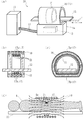
The configuration of an embodiment (first embodiment) of the living body warming device of the present invention will be described with reference to the drawings. 1A is a perspective view of the living
この生体加温装置10は、膀胱癌や馬尾神経腫瘍などの局部温熱療法に好適なものであり、従来品と同様、図示しない横送り機構の付いた可動寝台15(生体保持具)と、架台14上に横置きされた筒状枠体16と、軸方向を水平にした状態で筒状枠体16に納められ可動寝台15を遊挿しうる大形のソレノイドコイル17と、ケーブル12やマッチングボックス13を介してソレノイドコイル17に高周波を給電するための高周波電源11とを備えたものであるが、ソレノイドコイル17及び筒状枠体16の横断面形状が、従来と異なり、横断面D字形となっている。
The living
すなわち、可動寝台15上に患者が横たわったときに患者がソレノイドコイル17の中心に位置するよう可動寝台15はソレノイドコイル17の中空内でソレノイド軸より下方へ偏倚したところに設置されるが、その偏倚側が変形している。ソレノイドコイル17の横断面形状はソレノイドコイル17の全長に亘ってほぼ同一なので、その横断面形状について詳述すると(図1(c)参照)、ソレノイドコイル17のうち可動寝台15の非偏倚側である可動寝台15の両脇とその上側部分は、従来通り円弧状のままであって、その円弧状部分17aがその延長にて仮想される円の半分以上を占めているが、ソレノイドコイル17のうち可動寝台15の偏倚側である可動寝台15の下方の部分は、直線状部分17bになっている。
That is, when the patient lies on the
直線状部分17bは、両端の遷移部分を除いて真っ直ぐな直線になっていて、従来は実在していた上記仮想円の内側を通って上側円弧の両端を短絡経路で結んでいる。この直線状部分17bの幅と可動寝台15の幅とがほぼ同じ例を図示したが、他の部材との取り合い等によっては、両者の幅に差が生じることがある。また、直線状部分17bが完全な直線から概ね直線と言える近似直線になることもある。例えば、僅かに折れている折れ線や、曲率半径の大きい緩やかな曲線になることもありうるが、円弧状部分17aの形状より直線に近い形状であれば直線状と言える。
The
この実施形態(第1形態)の生体加温装置について、その使用態様及び動作を、図面を引用して説明する。図1(d)は、患者8(生体、被射体)に磁気を照射しているところの縦断面模式図である。 About the living body warming device of this embodiment (1st form), the use aspect and operation | movement are demonstrated referring drawings. FIG.1 (d) is a longitudinal cross-sectional schematic diagram of the place which has irradiated the patient 8 (living body, to-be-photographed object) with magnetism.
先ず微粒子の感磁発熱体を注入した患者8を可動寝台15に乗せるが、その際、患部8aが上側になるよう、例えば患部8aが腰部にあればうつ伏せ状態で、横たわらせる。それから、その状態を維持したまま、可動寝台15を移動させて筒状枠体16及びソレノイドコイル17の中空内に患者8を送り込む。そして、感磁発熱体が患部に凝集した頃に高周波電源11を作動させると、ソレノイドコイル17の軸方向すなわち患者8の身長方向に延びる磁束9が生じる。その際、磁束9が患部8aのところで治療に必要な高い密度になるよう、高周波電源11の出力が調整されるが、その際、従来と同じコイル電流(ひいては磁束密度)が従来より低い出力電圧で得られる。それは即ち、従来と同じ出力電圧を以て従来より増強されたコイル電流や磁束密度が得られるということであり、その効用は大である。
First, the
これは、ソレノイドコイル17の捲回数が従来と同じでも短絡線状部分17bの変形によりソレノイドコイル17のインピーダンスが減ったためである。例えば、磁束の交番周波数が感磁発熱体に磁気ヒステリシス損を発生させるのに好適な50kHz〜400kHz程度であって電流が200A程度の高周波をソレノイドコイル17に給電するとして、従来であれば20μH程度であったインダクタンスが15μH程度になるので、それに対応して高周波電源11の出力電圧は15kVから10kV程度に低下する。
This is because the impedance of the
本発明の生体加温装置の他の実施形態(第2形態)について、その構成を、図面を引用して説明する。図2は、(a)が生体加温装置20の斜視図、(b)が磁束照射部の縦断面図、(c)が磁束照射部の横断面図である。
The configuration of another embodiment (second embodiment) of the living body warming device of the present invention will be described with reference to the drawings. 2A is a perspective view of the living
この生体加温装置20が上述した生体加温装置10と相違するのは、横断面D字形の副ソレノイドコイル21が追加された点である。
副ソレノイドコイル21は、ソレノイドコイル17と同じく横置き状態で可動寝台15を遊挿しうるものであるが、ソレノイドコイル17に内挿されるので、ソレノイドコイル17より一回り小さく、横断面形状において可動寝台15の非偏倚側が円弧状で可動寝台15の偏倚側が直線状になっている。また、長さがソレノイドコイル17より短く、素線径がソレノイドコイル17より細く、巻きピッチが細かくて捲回密度がソレノイドコイル17より密になっている。
This
The
両コイルを対比して数値例を挙げると、ソレノイドコイル17は、円弧状部分17aの直径が500mm程度で、素線径が20mm程度で、捲回ピッチが50mm程度で、捲回数が10程度である。
これに対し、副ソレノイドコイル21は、円弧状部分の直径が470mm程度で、素線径が10mm程度で、捲回ピッチが20mm程度で、捲回数が4程度である。
このような副ソレノイドコイル21は、ソレノイド軸方向における中央かその近傍でソレノイドコイル17に固定して内挿され或いは可動寝台15と共に又は単独で軸方向移動されてソレノイドコイル17に内挿され、同位相での通電を簡便かつ確実に行うためソレノイドコイル17と直列に接続される。
As a numerical example comparing the two coils, the
In contrast, the
Such a
この実施形態(第2形態)の生体加温装置20について、その使用態様及び動作を、図面を引用して説明する。図2(d)は、患者8に磁気を照射しているところの縦断面模式図である。
About the
患部8aを上側にして感磁発熱体注入後の患者8を可動寝台15に乗せてソレノイドコイル17の中空内に患者8を送り込み、それから高周波電源11を作動させるという手順は上述したのと同じであるが、この場合は、患部8aを副ソレノイドコイル21の内側に位置させたところで可動寝台15を止めておく。そうすると、ソレノイドコイル17の発生する磁界に副ソレノイドコイル21の発生する磁界が重畳するので、患者8の身長方向に延びる磁束9が患部8aのところで絞られて密になる。また、副ソレノイドコイル21の追加によってソレノイドコイル17と合わせたコイルの総捲回数が増えている。
The procedure of placing the
そのため、患部8aに所期の密度の磁束9を生じさせるのに要するコイル電流が少なくて済むので、ソレノイドコイル17と副ソレノイドコイル21とが直列になっていても、高周波電源11の出力調整に際して出力電圧を上げる必要のないケースが多く、副ソレノイドコイル21による磁束9の絞り効果やソレノイドコイル17の短絡線状部分17bの変形によるインピーダンス低減効果とが相まって、高周波電源11の出力電圧を下げることが可能となるケースもある。出力電圧はしばしば変動するので目安にすぎないが、一例を挙げると、感磁発熱体の発熱機能に適う例えば300mT(ミリ・テスラ)の磁束9を患部8aのところに生じさせるとき、従来装置の出力電圧は20kV程度であったが、生体加温装置20の高周波電源11の出力電圧は10kV程度である。
Therefore, less coil current is required to generate the
本発明の生体加温装置の他の実施形態(第3形態)について、その構成を、図面を引用して説明する。図3(a)は、ソレノイドコイル17及び副ソレノイドコイル23並びに可動寝台15の縦断面図である。
The configuration of another embodiment (third embodiment) of the living body warming device of the present invention will be described with reference to the drawings. FIG. 3A is a longitudinal sectional view of the
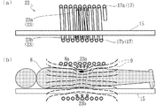
この生体加温装置22が上述した生体加温装置20と相違するのは副ソレノイドコイル21が一部変形されて副ソレノイドコイル23になった点であり、副ソレノイドコイル23が副ソレノイドコイル21と相違するのは、横断面D字形を維持したまま、可動寝台15偏倚側のコイル捲回ピッチが例えば2倍に広がって副ソレノイドコイル23のうち可動寝台15の下方の部分が粗巻部23bになった点である。副ソレノイドコイル23のうち可動寝台15の上方の部分はソレノイドコイル17より密に捲回された密巻部23aのままである。
This
この実施形態(第3形態)の生体加温装置22について、その使用態様及び動作を、図面を引用して説明する。図3(b)は、患者8に磁気を照射しているところの縦断面模式図である。
この場合、患者8の身体のうち密巻部23a寄りの患部8aには上述の生体加温装置20と同じく磁束9が集中するのに対し、患者8の身体のうち粗巻部23b寄りの正常部位では磁束9が生体加温装置20のときより分散するので、正常部位に掛かる負担が少なくなる。他は生体加温装置20のときと同様である。
About the
In this case, the
本発明の生体加温装置の他の実施形態(第4形態)について、その構成を、図面を引用して説明する。図4(a)は、ソレノイドコイル17及び副ソレノイドコイル25並びに可動寝台15の縦断面図である。
The configuration of another embodiment (fourth embodiment) of the living body warming device of the present invention will be described with reference to the drawings. FIG. 4A is a longitudinal sectional view of the
この生体加温装置24が上述した生体加温装置22と相違するのは副ソレノイドコイル23がそれより細い副ソレノイドコイル25になった点であり、副ソレノイドコイル25は、横断面D字形のまま、径が小さくなったので、可動寝台15から外され、ソレノイドコイル17の中空の何処にでも自在に移して置けるよう給電ケーブルがフレキシブルになっている。このような副ソレノイドコイル25はソレノイドコイル17から出し入れするのも自在なので、ソレノイドコイル17から出して給電を絶つことができるよう、給電経路をソレノイドコイル17だけとソレノイドコイル17及び副ソレノイドコイル25とで切り替えるスイッチ等が設けられている。あるいは、給電ケーブルの挿抜等にて副ソレノイドコイル25を完全に切り離すことのできるアタッチメント化が図られている。
This
この実施形態(第4形態)の生体加温装置24について、その使用態様及び動作を、図面を引用して説明する。図4(b)は、患者8に磁気を照射しているところの縦断面模式図である。
患部8aが足や手にあるような場合、患部8aを囲む状態で副ソレノイドコイル25を足や手に外嵌し、患部8a及び副ソレノイドコイル25がソレノイドコイル17の中空に入るところに可動寝台15を止め、他は生体加温装置20,22について上述したのと同様にして磁束9を発生させれば、磁束9が患部8aに対して集中的に照射される。
また、患部8aが胴体にあるような場合には、副ソレノイドコイル25をソレノイドコイル17から出すとともに、副ソレノイドコイル25への給電を絶ち、ソレノイドコイル17だけに給電すれば、生体加温装置10について上述したのと同様の磁束照射が行われる。
About the
When the
Further, when the
本発明の生体加温装置の他の実施形態(第5形態)について、その構成を、図面を引用して説明する。図5は、(a)が生体加温装置26の斜視図、(b)が磁束照射部の縦断面図である。
この生体加温装置26は、乳癌などの局部温熱療法に好適なものであり、上述した生体加温装置20,22と相違するのは、ソレノイドコイル17の中空に遊挿可能な磁性体27が追加された点である。
The configuration of another embodiment (fifth embodiment) of the living body warming device of the present invention will be described with reference to the drawings. 5A is a perspective view of the living
This living
磁性体27は、例えば焼結フェライトなどの強磁性体からなり、この例では棒切れ状(棒片状、直線状、真っ直ぐな棒状)に形成されている。磁性体27は、ソレノイドコイル17の中空内で磁束を患部に集中させるためのものなので、サイズや形状が患部に適合させられ、例えば乳癌用では直径が数cmで長さが数十cmの丸棒状になっている。更には患部の形状に応じて、L形,三ヶ月形などの異形片状とすることもできる。
The
この実施形態(第5形態)の生体加温装置26について、その使用態様及び動作を、図面を引用して説明する。図5(c)は患者8(生体、被射体)に磁気を照射しているところの縦断面模式図である。
About the living
微粒子の感磁発熱体を注入した患者8を可動寝台15に乗せて横たわらせてから、磁性体27の一端を作用端として患部に向けさせ、その状態を維持したまま、可動寝台15を移動させて筒状枠体16及びソレノイドコイル17の中空内に患者8を送り込む。そして、患部が副ソレノイドコイル21又は23の中空内に入ったところで可動寝台15を止めておき、感磁発熱体が患部に凝集した頃に高周波電源11を作動させると、ソレノイドコイル17の軸方向すなわち患者8の身長方向に延びる磁束9が生じる。この磁束9は、副ソレノイドコイル21,23のところで全体的・大局的に絞られるうえ、磁性体27のところで局所的に強く集束されて、患部に高密度で照射される一方、それ以外のところではソレノイドコイル17中空内において径方向に拡散・分散しながらソレノイドコイル17の両端へ延びる。
The
そのため、患部には感磁発熱体の発熱機能に適う例えば300mT(ミリ・テスラ)の磁束を照射した場合でも、それ以外の体表面では10〜100mT程度しか照射されないので、磁束の交番周波数が感磁発熱体に磁気ヒステリシス損を発生させるのに好適な50kHz〜400kHz程度の高周波であっても、正常な体表面を不所望に誘導加熱するおそれが無い。
したがって、この生体加温装置26にあっては、患者8に不所望な副作用的損傷を与えることなく、乳癌等の患部すなわち生体の局所には高密度の磁束を照射して十分に加温することができる。
Therefore, even if the affected part is irradiated with a magnetic flux of 300 mT (milli tesla) suitable for the heat generating function of the magnetosensitive heating element, only about 10 to 100 mT is irradiated on the other body surface. Even at a high frequency of about 50 kHz to 400 kHz suitable for generating a magnetic hysteresis loss in the magnetic heating element, there is no possibility that the normal body surface is undesirably induction heated.
Therefore, in this living
本発明の生体加温装置の他の実施形態(第6形態)について、その構成を、図面を引用して説明する。図6は、(a)が生体加温装置28の斜視図、(b)が磁束照射部の縦断面図である。
The configuration of another embodiment (sixth embodiment) of the living body warming device of the present invention will be described with reference to the drawings. 6A is a perspective view of the living
この生体加温装置28が上述した生体加温装置26と相違するのは、深奥患部への磁気照射のため、単一の磁性体27が複数の磁性体29a,29bになって更にそれらがソレノイドコイル17の軸方向に分離した状態で配置されている点である。
磁性体29a,29bは、何れも、焼結フェライトなどの強磁性体からなり、太さがテーパ状に変化する筒状体であるが、筒状枠体16よりも径が小さく長さが半分未満で、軸方向に分離配置しても筒状枠体16の中空に遊挿しうるものとなっている。筒状枠体16より細いとは言っても、可動寝台15を挿通可能な程度には太い。
This
Each of the
この実施形態(第6形態)の生体加温装置28について、その使用態様及び動作を、図面を引用して説明する。図6(c)は患者8の腹部に磁気を照射しているところの縦断面模式図である。
About the living
膀胱癌や内臓の癌などでは患部が患者8の腹胸の深奥部に存在するので、磁性体29a,29bの細径端を対向させることにより、両者の間で磁束を絞り込み、患部の磁束密度を高める。詳述すると、微粒子の感磁発熱体を注入した患者8を可動寝台15に乗せて横たわらせ、患部が副ソレノイドコイル21又は23の中空内に入るよう位置合わせしながら副ソレノイドコイル21又は23を可動寝台15に固定し、それから、一方の例えば左方の磁性体29aは、太径端を左にし細径端を右にした状態で左から可動寝台15及び患者8に嵌装し、右方に配置される他方の磁性体29bは、太径端を右にし細径端を左にした状態で右から可動寝台15及び患者8に嵌装し、両者の中間に副ソレノイドコイル21,23が位置するとともに両者の間隙に患者8の患部が来たところで、磁性体29a,29bと可動寝台15との相対位置を固定する。
In the case of bladder cancer or visceral cancer, the affected part exists in the deep part of the abdominal chest of the
それによって患者8と副ソレノイドコイル21又は23と磁性体29a,29bとの相対位置も固定されるので、その状態を維持したまま、可動寝台15を移動させて筒状枠体16及びソレノイドコイル17の中空内に患者8を送り込む。そして、この場合も、感磁発熱体が患部に凝集した頃に高周波電源11を作動させると、ソレノイドコイル17の軸方向すなわち患者8の身長方向に延びる磁束9が生じる。この磁束9は、副ソレノイドコイル21又は23のところ即ち磁性体29a,29bの細径端の間で集束されて、患者8の腹部深奥の患部に高密度で照射される一方、磁性体29a,29bの太径端や更に外側のところではソレノイドコイル17中空内において径方向に拡散・分散しながらソレノイドコイル17の両端へ延びる。
As a result, the relative positions of the
そのため、この生体加温装置28にあっても、患者8に不所望な副作用的損傷を与えることなく、内臓器癌等の患部すなわち生体の深奥部の局所に高密度の磁束を照射して、そこを十分に加温することができる。
なお、磁性体29a,29bの形状については、テーパ状の筒体を図示したが、副ソレノイドコイル21,23同様、横断面D字形にしても良く、具体的には可動寝台15偏倚側部分を可動寝台15と平行な平面に変形しても良い。
Therefore, even in this living
As for the shapes of the
本発明の生体加温装置の他の実施形態(第7形態)について、その構成を、図面を引用して説明する。図7は、(a)が生体加温装置30の斜視図、(b)が磁束照射部の縦断面図、(c)が中実状磁性体40の斜視図、(d)が中空状磁性体50の斜視図である。また、図8は、生体加温装置30の回路ブロック図である。
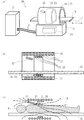
The configuration of another embodiment (seventh embodiment) of the living body warming device of the present invention will be described with reference to the drawings. 7A is a perspective view of the
この生体加温装置30が上述した生体加温装置28と相違するのは(図7(a),(b)参照)、前立腺癌を狙い撃ちするために下半身側の磁性体29bが磁束収束用の中実状磁性体40になった点と、頭部や胸部への磁気作用を最小限に抑えるために上半身側の磁性体29aが磁束拡散用の中空状磁性体50になった点である。
中空状磁性体50は、その中空に可動寝台15を挿通させた状態で且つ図示しないスライド機構にて軸方向へ即ち可動寝台15の長手方向へ相対移動可能な状態で、可動寝台15に装着されており、中実状磁性体40は、一部を可動寝台15から上に突き出す状態で、可動寝台15に差し込み固定され、架台14とケーブル31で接続されている。副ソレノイドコイル21又は23は可動寝台15の長手方向において中空状磁性体50と中実状磁性体40との中間に移動して固定できるよう設置されている。
The
The hollow
中実状磁性体40は(図7(c)参照)、人間の股の間に収まる比較的小形の磁性体本体41を主体にしたものである。磁性体本体41は、例えば平面状,曲面状に形成された小さい頂部を有する台形状あるいは頂部を切り取った角錐・円錐状等の、頂部に向かって断面積が小さくなって行く形態の強磁性材小片からなり、その頂部を作用端面42として患部に向け、軸線を可動寝台15の長手方向と平行にした配位で可動寝台15に取り付けられる。磁性体本体41には、作用端面42及び非作用端面43を貫く磁束を強化するために、小形ソレノイドコイル44が捲回されている。小形ソレノイドコイル44は(図8参照)、ケーブル31内の高周波電線34でマッチングボックス13に接続されており、ソレノイドコイル17と共に高周波電源11にて高周波通電されるようになっている。
The solid magnetic body 40 (see FIG. 7C) is mainly composed of a relatively small
また、磁性体本体41の作用端面42には(図7(c)参照)、作用端面42と対向する生体表面の温度を検出する体表面温度検出部材45が付設されている。体表面温度検出部材45は、例えば半導体センサを組み込んだ温度計からなり、患部の表面温度を測定するため、感温部は作用端面42から露出させ感温部以外は断熱材を被せた状態で、作用端面42に埋設されている。体表面温度検出部材45は(図8参照)、ケーブル31内の信号線35にて高周波電源11に接続されており、体表面温度検出部材45の検出温度が高周波通電の制御に利用できるようになっている。例えば、体表面温度検出部材45の検出温度が42℃を超えると、高周波電源11が出力を弱めるようになっている。
Further, a body surface
さらに、磁性体本体41の内部には(図7(c)参照)、そこの温度を検出するため例えば半導体センサを組み込んだ内部温度検出部材46が埋設されている。内部温度検出部材46も(図8参照)、ケーブル31内の信号線36にて高周波電源11に接続されており、その検出温度が高周波通電の制御に利用できるようになっている。中実状磁性体40の磁気変態温度にもよるが、例えば、内部温度検出部材46の検出温度が100℃を超えると、中実状磁性体40の磁化率が不所望に下がる場合には、それを防止するため、上記温度を境として高周波電源11が出力を弱めるようになっている。
Furthermore, an internal
磁性体本体41には(図7(c)参照)、積極的な冷却のため磁性体冷却手段も設けられている。具体的には、磁性体本体41にはその内部を巡るようにして例えばUターンする冷媒流路47が形成されており、それが(図8参照)ケーブル31内のフレキシブル配管37にて冷却水循環装置38に接続されていて、中実状磁性体40もマッチングボックス13やソレノイドコイル17さらには副ソレノイドコイル21又は23と同様に水冷されるようになっている。
The magnetic body 41 (see FIG. 7C) is also provided with a magnetic body cooling means for positive cooling. Specifically, the
中空状磁性体50(図7(d)参照)は、磁性体29aと同様に強磁性体からなる筒状体であり、外径が筒状枠体16の内径よりも小さく内径が可動寝台15の横幅よりも大きくて可動寝台15と筒状枠体16との間に遊挿しうるものとなっている(図7(a),(b)参照)。中空状磁性体50は、長さが筒状枠体16の半分以下で、中実状磁性体40と共に軸線がソレノイドコイル17の軸線と平行となる配位でソレノイドコイル17内に分離配置されるようになっている。磁性体29aと同じく太さがテーパ状に変化する筒状体であっても良いが、ここでは、磁束拡散機能を発揮すれば足りるので、全長に亘って同径の筒状体になっている。
The hollow magnetic body 50 (see FIG. 7D) is a cylindrical body made of a ferromagnetic material like the
このような大径の中空状磁性体50を総て強磁性体で作るのは材工費が嵩むので、実用的な中空状磁性体50として、例えば(図7(d)参照)、棒状の磁性体本体51を環状に並べて筒状枠体52にプラスチックモールドしたものを用いてもよい。更には、プラスチックモールドの代りにベルト状の可撓体に装着した態様、或いは強磁性体の粉粒体をゴムや軟質プラスチックに練り込んだ構成のベルト材が、生体にフィットさせて装着できる点などにおいて有用である。この中空状磁性体50も、副ソレノイドコイル21,23同様、下側部分の平らな横断面D字形になっている。
It is expensive to manufacture such a large-diameter hollow
この実施形態(第7形態)の生体加温装置30について、その使用態様及び動作を、図面を引用して説明する。図9は、患者8に磁気を照射しているところの横断面模式図である。ここでは、患者8の前立腺癌を局部温熱療法で治療するものとする。
About the living
先ず、微粒子の感磁発熱体を注入した患者8を可動寝台15に乗せて横たわらせるが、その際、中実状磁性体40が作用端面42を患者8の下腹部に向け非作用端面43を患者8の下肢間を向く状態で患者8の股間に収まるようにする。それから、副ソレノイドコイル21又は23を可動寝台15長手方向にスライド移動させて、患者8の患部を囲むところに副ソレノイドコイル21又は23を位置させ、それから、中空状磁性体50を可動寝台15長手方向にスライド移動させて、患者8の胸を囲むところに中空状磁性体50を位置させる。そうすると、可動寝台15を基準にして中実状磁性体40と副ソレノイドコイル21又は23と中空状磁性体50と患者8との相対位置が固定されるので、その状態を維持したまま、可動寝台15を移動させて筒状枠体16及びソレノイドコイル17の中空内に患者8を送り込む。
First, the
そして、感磁発熱体が患部に凝集した頃に高周波電源11を作動させると、患者8を包む筒状枠体16中空の全域について概括すれば、この場合も、上述したようにソレノイドコイル17の軸方向すなわち患者8の身長方向に延びる磁束9が生じる。この磁束9は、副ソレノイドコイル21,23のところで全体的・大局的に絞られるうえ、中実状磁性体40のところで磁性体本体41によって集束されるばかりか小形ソレノイドコイル44によって更に強化され、生体内奥の患部に高密度で照射される一方、ソレノイドコイル17中空内において、中空状磁性体50のところでは径方向に速やかに拡散・分散し、中実状磁性体40の非作用端面43の先(図では右方)では緩やかに拡散・分散しながらソレノイドコイル17の両端へ延びる。
Then, when the high
そのとき、中実状磁性体40においては、磁性体本体41が小形ソレノイドコイル44の交番磁界等によって発熱し、その熱は冷却水循環装置38によって取り去られるが、その冷却を発熱が上回ると、磁性体本体41の不所望な昇温が内部温度検出部材46によって検出され、それに応じて高周波電源11の出力が抑制的に調整されるので、中実状磁性体40の磁束集束能力および磁束強化能力が適正に維持される。また、患者8の股間の温度が不所望に上昇すると、それが体表面温度検出部材45によって検出され、それに応じて高周波電源11の出力が抑制的に調整されるので、患者8の正常な体表面は患部近傍であっても不所望に加熱されることがない。
At that time, in the solid
もちろん、患部から離れたところの体表面については、そこを貫く磁束が拡散・分散ししていて、磁束密度の勾配が小さいことから、交番磁界による誘導電流が少ないので、そこも不所望に加熱されることがない。
そのため、この生体加温装置30にあっては、患者8に不所望な副作用的損傷を与えることなく、前立腺癌等の患部すなわち生体の深奥部の局所に高密度の磁束を照射して、そこだけを十分に加温することができる。
Of course, on the body surface away from the affected area, the magnetic flux penetrating there is diffused and dispersed, and since the gradient of the magnetic flux density is small, the induced current due to the alternating magnetic field is small, so it is also heated undesirably. It will not be done.
For this reason, the living
[その他]
上記の各形態では、可動寝台15を横送りするようになっていたが、その代わりにソレノイドコイル17や副ソレノイドコイル21等を移動させても良く、可動寝台15とソレノイドコイル17等を何れも移動させるようにしても良い。
また、上記の各形態では、可動寝台15もソレノイドコイル17も横置きされていたが、それらは、縦置きでも良く、傾斜していても良い。
さらに、生体保持具は、ソレノイドコイル17の直線状部分17b側に偏倚した可動寝台15に限られない。例えば、溝形樋状部材でソレノイドコイル17の円弧状部分17aの内面にピッタリ嵌るものでも良く、患者8が寄り掛かったり掴まり立ちして使用するようになっていても良い。
[Others]
In each of the above embodiments, the
Moreover, in each said form, although the
Furthermore, the living body holder is not limited to the
また、上記の第7形態では、内部温度検出部材46の検出結果を高周波電源11の出力制御にだけ用いるようになっていたが、内部温度検出部材46の検出温度に応じて冷却水循環装置38の供給する水温や水量を調節するようにしても良く、併用しても良い。
また、一台の高周波電源11でソレノイドコイル17と副ソレノイドコイル21又は23と小形ソレノイドコイル44とに給電するようになっていたが、各ソレノイドコイル毎に個別の高周波電源(個別の高周波出力部を含む)を設置し夫々の位相を揃える制御の下で稼働させても良く、高周波電源の共用と専用とが共存していても良い。
Further, in the seventh embodiment, the detection result of the internal
Further, the single high-
8…患者(被射体、生体)、8a…患部、9…磁束、
10…生体加温装置、11…高周波電源、12…ケーブル、
13…マッチングボックス、14…架台、
15…可動寝台(生体保持具)、16…筒状枠体、
17…ソレノイドコイル、17a…円弧状部分、17b…短絡線状部分、
20…生体加温装置、21…副ソレノイドコイル、
22…生体加温装置、23…副ソレノイドコイル、
23a…密巻部、23b…粗巻部、
24…生体加温装置、25…副ソレノイドコイル、
26…生体加温装置、27…磁性体、
28…生体加温装置、29a,29b…磁性体、
30…生体加温装置、31…ケーブル、34…高周波電線、
35,36…信号線、37…配管、38…冷却水循環装置、
40…中実状磁性体、41…磁性体本体、42…作用端面、
43…非作用端面、44…小形ソレノイドコイル、
45…体表面温度検出部材、46…内部温度検出部材、47…冷媒流路、
50…中空状磁性体、51…磁性体本体、52…筒状枠体
8 ... Patient (subject, living body), 8a ... affected area, 9 ... magnetic flux,
10 ... living body warming device, 11 ... high frequency power supply, 12 ... cable,
13 ... Matching box, 14 ... Frame,
15 ... movable bed (biological holder), 16 ... cylindrical frame,
17 ... Solenoid coil, 17a ... Arc-shaped part, 17b ... Short-circuited line part,
20 ... living body warming device, 21 ... sub-solenoid coil,
22 ... Living body warming device, 23 ... Sub solenoid coil,
23a ... densely wound portion, 23b ... coarsely wound portion,
24 ... Living body warming device, 25 ... Sub solenoid coil,
26 ... Living body warming device, 27 ... Magnetic body,
28 ... Living body warming device, 29a, 29b ... Magnetic material,
30 ... living body heating device, 31 ... cable, 34 ... high frequency electric wire,
35, 36 ... signal line, 37 ... piping, 38 ... cooling water circulation device,
40 ... solid magnetic body, 41 ... magnetic body, 42 ... working end face,
43 ... non-acting end face, 44 ... small solenoid coil,
45 ... Body surface temperature detection member, 46 ... Internal temperature detection member, 47 ... Refrigerant flow path,
50 ... Hollow magnetic body, 51 ... Magnetic body, 52 ... Cylindrical frame
Claims (17)
前記ソレノイドコイルはその横断面に係る輪郭の形状が該輪郭の周方向における過半区間では円弧状であって残りの区間では直線状であり且つ前記直線状区間が総て前記生体保持具より下方に位置しており前記円弧状区間が前記生体保持具より上方の部分を占めており而も前記円弧状区間がそれを延長して仮想円を想定しうるものであり前記直線状区間が前記仮想円の内側を通って前記円弧状区間の両端を短絡経路で結んでおり、
更に、前記ソレノイドコイルより小さく且つ短くて前記ソレノイドコイルに遊挿可能な磁性体を設け、この磁性体を前記生体保持具と共に前記ソレノイドコイルの前記中空内に入れることにより、前記ソレノイドコイルの前記中空内でそこの磁束を前記磁性体のところでは集中させるが他のところでは分散させながら前記生体保持具上に照射するようになっていることを特徴とする生体加温装置。 A cylindrical coil of a size that allows a living body to be loosely inserted into the hollow, and when energized, a solenoid coil that generates a magnetic flux extending in the axial direction of the coil within the hollow, a high-frequency power source for supplying power thereto, In a living body warming device provided with a living body holder such as a movable bed that can be loosely inserted into the hollow of the solenoid coil in a state of being placed on the floor,
The solenoid coil has a cross-sectional shape in which the contour shape is an arc in a majority section in the circumferential direction of the contour, and is linear in the remaining sections, and the linear sections are all below the living body holder. The arcuate section occupies a portion above the living body holder, and the arcuate section can be extended to assume a virtual circle, and the linear section is the virtual circle. The ends of the arc-shaped section through the inner side of the short circuit path ,
Furthermore, a magnetic body that is smaller and shorter than the solenoid coil and that can be loosely inserted into the solenoid coil is provided, and the magnetic body is placed in the hollow of the solenoid coil together with the living body holder, thereby the hollow of the solenoid coil. The living body heating apparatus is characterized in that the magnetic flux there is concentrated on the magnetic body but irradiated on the living body holder while being dispersed elsewhere.
Priority Applications (1)
| Application Number | Priority Date | Filing Date | Title |
|---|---|---|---|
| JP2006096064A JP4966575B2 (en) | 2006-03-30 | 2006-03-30 | Biological heating device |
Applications Claiming Priority (1)
| Application Number | Priority Date | Filing Date | Title |
|---|---|---|---|
| JP2006096064A JP4966575B2 (en) | 2006-03-30 | 2006-03-30 | Biological heating device |
Publications (2)
| Publication Number | Publication Date |
|---|---|
| JP2007267875A JP2007267875A (en) | 2007-10-18 |
| JP4966575B2 true JP4966575B2 (en) | 2012-07-04 |
Family
ID=38671291
Family Applications (1)
| Application Number | Title | Priority Date | Filing Date |
|---|---|---|---|
| JP2006096064A Active JP4966575B2 (en) | 2006-03-30 | 2006-03-30 | Biological heating device |
Country Status (1)
| Country | Link |
|---|---|
| JP (1) | JP4966575B2 (en) |
Cited By (3)
| Publication number | Priority date | Publication date | Assignee | Title |
|---|---|---|---|---|
| US10342989B2 (en) | 2013-09-20 | 2019-07-09 | Dai-Ichi High Frequency Co., Ltd. | Magnetic flux irradiation devices and components |
| US10500409B2 (en) | 2015-03-02 | 2019-12-10 | KAIO Therapy, LLC | Systems and methods for providing alternating magnetic field therapy |
| US10576297B2 (en) | 2013-09-20 | 2020-03-03 | Dai-Ichi High Frequency Co., Ltd. | Magnetic flux irradiation devices and components |
Families Citing this family (2)
| Publication number | Priority date | Publication date | Assignee | Title |
|---|---|---|---|---|
| ES2371210T3 (en) * | 2008-03-28 | 2011-12-28 | Magforce Nanotechnologies Ag | APPLICATION DEVICE FOR ALTERNATE MAGNETIC FIELD FOR WARMING OF MAGNETIC OR MAGNETIZABLE SUBSTANCES IN BIOLOGICAL FABRIC. |
| CN108144185B (en) * | 2018-01-22 | 2021-08-17 | 崔梓华 | Coil structure, magnetic therapy instrument with coil structure and magnetic therapy method |
Family Cites Families (5)
| Publication number | Priority date | Publication date | Assignee | Title |
|---|---|---|---|---|
| JPS55160720A (en) * | 1979-05-29 | 1980-12-13 | Mochida Pharmaceut Co Ltd | Remedial composition for cancer and its remedial device |
| JPS61154575A (en) * | 1984-12-28 | 1986-07-14 | 斎藤 行正 | Health coil apparatus |
| JPH045172Y2 (en) * | 1987-08-27 | 1992-02-14 | ||
| JPH0533165Y2 (en) * | 1988-10-29 | 1993-08-24 | ||
| JP2004237050A (en) * | 2003-02-06 | 2004-08-26 | Takahiro Hara | Warming device |
-
2006
- 2006-03-30 JP JP2006096064A patent/JP4966575B2/en active Active
Cited By (3)
| Publication number | Priority date | Publication date | Assignee | Title |
|---|---|---|---|---|
| US10342989B2 (en) | 2013-09-20 | 2019-07-09 | Dai-Ichi High Frequency Co., Ltd. | Magnetic flux irradiation devices and components |
| US10576297B2 (en) | 2013-09-20 | 2020-03-03 | Dai-Ichi High Frequency Co., Ltd. | Magnetic flux irradiation devices and components |
| US10500409B2 (en) | 2015-03-02 | 2019-12-10 | KAIO Therapy, LLC | Systems and methods for providing alternating magnetic field therapy |
Also Published As
| Publication number | Publication date |
|---|---|
| JP2007267875A (en) | 2007-10-18 |
Similar Documents
| Publication | Publication Date | Title |
|---|---|---|
| WO2008026254A1 (en) | Organism heater | |
| RU2635653C2 (en) | Device for energy field generation for treatment of body cavities cancer and cavity organs cancer | |
| JP4966575B2 (en) | Biological heating device | |
| RU2499617C2 (en) | Apparatus for applying magnetic alternating field for heating magnetic or magnetised substances in biological tissue | |
| US6527694B1 (en) | Air-cooling device for coil for urinary incontinence treatment | |
| JP2009513258A5 (en) | ||
| Stauffer et al. | Practical induction heating coil designs for clinical hyperthermia with ferromagnetic implants | |
| JP6190809B2 (en) | Magnetic coil having two layers of spherical surface components | |
| US8062204B2 (en) | Coil device and magnetic field generating device | |
| KR20170115951A (en) | Device for Alternating Current Magnetic Field-induced Hyperthermia | |
| Nieskoski et al. | Comparison of a single optimized coil and a Helmholtz pair for magnetic nanoparticle hyperthermia | |
| Ho et al. | Design and analysis of a novel targeted magnetic fluid hyperthermia system for tumor treatment | |
| JP3737054B2 (en) | Magnetic flux irradiation device | |
| US20140081069A1 (en) | Deep magnetic field generating apparatus | |
| JP4731185B2 (en) | Living body internal heating device | |
| KR20130137831A (en) | Apparatus for hyperthermia using superparamagnetic colloids | |
| KR20200028581A (en) | Ac magnetic field generator using magnetic nanostructured materials for hyperthermia treatment of animals and humans in a biological and physiological safe range | |
| EP3628369B1 (en) | Magnetic field generating-apparatus for biostimulation | |
| Jian et al. | A novel targeted magnetic fluid hyperthermia system using HTS coil array for tumor treatment | |
| RU114863U1 (en) | DEVICE FOR IMPACT OF A MAGNETIC FIELD ON BIO-OBJECTS CONTAINING MAGNETIC NANOPARTICLES | |
| CN109662774B (en) | Non-invasive thermal ablation apparatus and method | |
| RU2066214C1 (en) | Magnetic therapeutic plant | |
| JP2005058298A (en) | Local heating method for inside of living body and magnetic flux irradiation apparatus | |
| Yosef et al. | The effects of frequency variation on the induced fields of transcranial magnetic stimulation systems | |
| JP2011156033A (en) | Magnetic flux irradiation device |
Legal Events
| Date | Code | Title | Description |
|---|---|---|---|
| A621 | Written request for application examination |
Free format text: JAPANESE INTERMEDIATE CODE: A621 Effective date: 20090225 |
|
| A131 | Notification of reasons for refusal |
Free format text: JAPANESE INTERMEDIATE CODE: A131 Effective date: 20110602 |
|
| A977 | Report on retrieval |
Free format text: JAPANESE INTERMEDIATE CODE: A971007 Effective date: 20110602 |
|
| A521 | Request for written amendment filed |
Free format text: JAPANESE INTERMEDIATE CODE: A523 Effective date: 20110715 |
|
| A131 | Notification of reasons for refusal |
Free format text: JAPANESE INTERMEDIATE CODE: A131 Effective date: 20111115 |
|
| A521 | Request for written amendment filed |
Free format text: JAPANESE INTERMEDIATE CODE: A523 Effective date: 20111212 |
|
| TRDD | Decision of grant or rejection written | ||
| A01 | Written decision to grant a patent or to grant a registration (utility model) |
Free format text: JAPANESE INTERMEDIATE CODE: A01 Effective date: 20120313 |
|
| A01 | Written decision to grant a patent or to grant a registration (utility model) |
Free format text: JAPANESE INTERMEDIATE CODE: A01 |
|
| A61 | First payment of annual fees (during grant procedure) |
Free format text: JAPANESE INTERMEDIATE CODE: A61 Effective date: 20120402 |
|
| R150 | Certificate of patent or registration of utility model |
Ref document number: 4966575 Country of ref document: JP Free format text: JAPANESE INTERMEDIATE CODE: R150 Free format text: JAPANESE INTERMEDIATE CODE: R150 |
|
| FPAY | Renewal fee payment (event date is renewal date of database) |
Free format text: PAYMENT UNTIL: 20150406 Year of fee payment: 3 |
|
| R250 | Receipt of annual fees |
Free format text: JAPANESE INTERMEDIATE CODE: R250 |
|
| R250 | Receipt of annual fees |
Free format text: JAPANESE INTERMEDIATE CODE: R250 |
|
| R250 | Receipt of annual fees |
Free format text: JAPANESE INTERMEDIATE CODE: R250 |
|
| R250 | Receipt of annual fees |
Free format text: JAPANESE INTERMEDIATE CODE: R250 |
|
| R250 | Receipt of annual fees |
Free format text: JAPANESE INTERMEDIATE CODE: R250 |
|
| R250 | Receipt of annual fees |
Free format text: JAPANESE INTERMEDIATE CODE: R250 |
|
| R250 | Receipt of annual fees |
Free format text: JAPANESE INTERMEDIATE CODE: R250 |
|
| R250 | Receipt of annual fees |
Free format text: JAPANESE INTERMEDIATE CODE: R250 |
|
| R250 | Receipt of annual fees |
Free format text: JAPANESE INTERMEDIATE CODE: R250 |