JP4966191B2 - Laser welding of conductive coated metal bipolar plates. - Google Patents
Laser welding of conductive coated metal bipolar plates. Download PDFInfo
- Publication number
- JP4966191B2 JP4966191B2 JP2007513171A JP2007513171A JP4966191B2 JP 4966191 B2 JP4966191 B2 JP 4966191B2 JP 2007513171 A JP2007513171 A JP 2007513171A JP 2007513171 A JP2007513171 A JP 2007513171A JP 4966191 B2 JP4966191 B2 JP 4966191B2
- Authority
- JP
- Japan
- Prior art keywords
- plate
- coating
- metal
- adjacent
- conductive
- Prior art date
- Legal status (The legal status is an assumption and is not a legal conclusion. Google has not performed a legal analysis and makes no representation as to the accuracy of the status listed.)
- Expired - Fee Related
Links
Images


Classifications
-
- H—ELECTRICITY
- H01—ELECTRIC ELEMENTS
- H01M—PROCESSES OR MEANS, e.g. BATTERIES, FOR THE DIRECT CONVERSION OF CHEMICAL ENERGY INTO ELECTRICAL ENERGY
- H01M8/00—Fuel cells; Manufacture thereof
- H01M8/02—Details
- H01M8/0202—Collectors; Separators, e.g. bipolar separators; Interconnectors
- H01M8/0204—Non-porous and characterised by the material
- H01M8/0206—Metals or alloys
- H01M8/0208—Alloys
- H01M8/021—Alloys based on iron
-
- B—PERFORMING OPERATIONS; TRANSPORTING
- B23—MACHINE TOOLS; METAL-WORKING NOT OTHERWISE PROVIDED FOR
- B23K—SOLDERING OR UNSOLDERING; WELDING; CLADDING OR PLATING BY SOLDERING OR WELDING; CUTTING BY APPLYING HEAT LOCALLY, e.g. FLAME CUTTING; WORKING BY LASER BEAM
- B23K26/00—Working by laser beam, e.g. welding, cutting or boring
- B23K26/20—Bonding
- B23K26/32—Bonding taking account of the properties of the material involved
-
- H—ELECTRICITY
- H01—ELECTRIC ELEMENTS
- H01M—PROCESSES OR MEANS, e.g. BATTERIES, FOR THE DIRECT CONVERSION OF CHEMICAL ENERGY INTO ELECTRICAL ENERGY
- H01M8/00—Fuel cells; Manufacture thereof
- H01M8/02—Details
- H01M8/0202—Collectors; Separators, e.g. bipolar separators; Interconnectors
- H01M8/0204—Non-porous and characterised by the material
- H01M8/0206—Metals or alloys
-
- H—ELECTRICITY
- H01—ELECTRIC ELEMENTS
- H01M—PROCESSES OR MEANS, e.g. BATTERIES, FOR THE DIRECT CONVERSION OF CHEMICAL ENERGY INTO ELECTRICAL ENERGY
- H01M8/00—Fuel cells; Manufacture thereof
- H01M8/02—Details
- H01M8/0202—Collectors; Separators, e.g. bipolar separators; Interconnectors
- H01M8/0204—Non-porous and characterised by the material
- H01M8/0223—Composites
- H01M8/0228—Composites in the form of layered or coated products
-
- H—ELECTRICITY
- H01—ELECTRIC ELEMENTS
- H01M—PROCESSES OR MEANS, e.g. BATTERIES, FOR THE DIRECT CONVERSION OF CHEMICAL ENERGY INTO ELECTRICAL ENERGY
- H01M8/00—Fuel cells; Manufacture thereof
- H01M8/02—Details
- H01M8/0202—Collectors; Separators, e.g. bipolar separators; Interconnectors
- H01M8/0258—Collectors; Separators, e.g. bipolar separators; Interconnectors characterised by the configuration of channels, e.g. by the flow field of the reactant or coolant
- H01M8/0263—Collectors; Separators, e.g. bipolar separators; Interconnectors characterised by the configuration of channels, e.g. by the flow field of the reactant or coolant having meandering or serpentine paths
-
- H—ELECTRICITY
- H01—ELECTRIC ELEMENTS
- H01M—PROCESSES OR MEANS, e.g. BATTERIES, FOR THE DIRECT CONVERSION OF CHEMICAL ENERGY INTO ELECTRICAL ENERGY
- H01M8/00—Fuel cells; Manufacture thereof
- H01M8/02—Details
- H01M8/0202—Collectors; Separators, e.g. bipolar separators; Interconnectors
- H01M8/0267—Collectors; Separators, e.g. bipolar separators; Interconnectors having heating or cooling means, e.g. heaters or coolant flow channels
-
- H—ELECTRICITY
- H01—ELECTRIC ELEMENTS
- H01M—PROCESSES OR MEANS, e.g. BATTERIES, FOR THE DIRECT CONVERSION OF CHEMICAL ENERGY INTO ELECTRICAL ENERGY
- H01M8/00—Fuel cells; Manufacture thereof
- H01M8/02—Details
- H01M8/0297—Arrangements for joining electrodes, reservoir layers, heat exchange units or bipolar separators to each other
-
- H—ELECTRICITY
- H01—ELECTRIC ELEMENTS
- H01M—PROCESSES OR MEANS, e.g. BATTERIES, FOR THE DIRECT CONVERSION OF CHEMICAL ENERGY INTO ELECTRICAL ENERGY
- H01M8/00—Fuel cells; Manufacture thereof
- H01M8/24—Grouping of fuel cells, e.g. stacking of fuel cells
- H01M8/2404—Processes or apparatus for grouping fuel cells
-
- H—ELECTRICITY
- H01—ELECTRIC ELEMENTS
- H01M—PROCESSES OR MEANS, e.g. BATTERIES, FOR THE DIRECT CONVERSION OF CHEMICAL ENERGY INTO ELECTRICAL ENERGY
- H01M8/00—Fuel cells; Manufacture thereof
- H01M8/24—Grouping of fuel cells, e.g. stacking of fuel cells
- H01M8/241—Grouping of fuel cells, e.g. stacking of fuel cells with solid or matrix-supported electrolytes
-
- H—ELECTRICITY
- H01—ELECTRIC ELEMENTS
- H01M—PROCESSES OR MEANS, e.g. BATTERIES, FOR THE DIRECT CONVERSION OF CHEMICAL ENERGY INTO ELECTRICAL ENERGY
- H01M8/00—Fuel cells; Manufacture thereof
- H01M8/24—Grouping of fuel cells, e.g. stacking of fuel cells
- H01M8/2465—Details of groupings of fuel cells
- H01M8/2483—Details of groupings of fuel cells characterised by internal manifolds
-
- B—PERFORMING OPERATIONS; TRANSPORTING
- B23—MACHINE TOOLS; METAL-WORKING NOT OTHERWISE PROVIDED FOR
- B23K—SOLDERING OR UNSOLDERING; WELDING; CLADDING OR PLATING BY SOLDERING OR WELDING; CUTTING BY APPLYING HEAT LOCALLY, e.g. FLAME CUTTING; WORKING BY LASER BEAM
- B23K2101/00—Articles made by soldering, welding or cutting
- B23K2101/34—Coated articles, e.g. plated or painted; Surface treated articles
-
- B—PERFORMING OPERATIONS; TRANSPORTING
- B23—MACHINE TOOLS; METAL-WORKING NOT OTHERWISE PROVIDED FOR
- B23K—SOLDERING OR UNSOLDERING; WELDING; CLADDING OR PLATING BY SOLDERING OR WELDING; CUTTING BY APPLYING HEAT LOCALLY, e.g. FLAME CUTTING; WORKING BY LASER BEAM
- B23K2103/00—Materials to be soldered, welded or cut
- B23K2103/08—Non-ferrous metals or alloys
-
- B—PERFORMING OPERATIONS; TRANSPORTING
- B23—MACHINE TOOLS; METAL-WORKING NOT OTHERWISE PROVIDED FOR
- B23K—SOLDERING OR UNSOLDERING; WELDING; CLADDING OR PLATING BY SOLDERING OR WELDING; CUTTING BY APPLYING HEAT LOCALLY, e.g. FLAME CUTTING; WORKING BY LASER BEAM
- B23K2103/00—Materials to be soldered, welded or cut
- B23K2103/50—Inorganic material, e.g. metals, not provided for in B23K2103/02 – B23K2103/26
-
- H—ELECTRICITY
- H01—ELECTRIC ELEMENTS
- H01M—PROCESSES OR MEANS, e.g. BATTERIES, FOR THE DIRECT CONVERSION OF CHEMICAL ENERGY INTO ELECTRICAL ENERGY
- H01M8/00—Fuel cells; Manufacture thereof
- H01M8/10—Fuel cells with solid electrolytes
- H01M2008/1095—Fuel cells with polymeric electrolytes
-
- Y—GENERAL TAGGING OF NEW TECHNOLOGICAL DEVELOPMENTS; GENERAL TAGGING OF CROSS-SECTIONAL TECHNOLOGIES SPANNING OVER SEVERAL SECTIONS OF THE IPC; TECHNICAL SUBJECTS COVERED BY FORMER USPC CROSS-REFERENCE ART COLLECTIONS [XRACs] AND DIGESTS
- Y02—TECHNOLOGIES OR APPLICATIONS FOR MITIGATION OR ADAPTATION AGAINST CLIMATE CHANGE
- Y02E—REDUCTION OF GREENHOUSE GAS [GHG] EMISSIONS, RELATED TO ENERGY GENERATION, TRANSMISSION OR DISTRIBUTION
- Y02E60/00—Enabling technologies; Technologies with a potential or indirect contribution to GHG emissions mitigation
- Y02E60/30—Hydrogen technology
- Y02E60/50—Fuel cells
-
- Y—GENERAL TAGGING OF NEW TECHNOLOGICAL DEVELOPMENTS; GENERAL TAGGING OF CROSS-SECTIONAL TECHNOLOGIES SPANNING OVER SEVERAL SECTIONS OF THE IPC; TECHNICAL SUBJECTS COVERED BY FORMER USPC CROSS-REFERENCE ART COLLECTIONS [XRACs] AND DIGESTS
- Y02—TECHNOLOGIES OR APPLICATIONS FOR MITIGATION OR ADAPTATION AGAINST CLIMATE CHANGE
- Y02P—CLIMATE CHANGE MITIGATION TECHNOLOGIES IN THE PRODUCTION OR PROCESSING OF GOODS
- Y02P70/00—Climate change mitigation technologies in the production process for final industrial or consumer products
- Y02P70/50—Manufacturing or production processes characterised by the final manufactured product
Description
本発明は、燃料電池に関し、より詳細には、燃料電池のバイポーラプレートを形成するために一緒にレーザ溶接される被覆金属プレートに関する。 The present invention relates to fuel cells and, more particularly, to coated metal plates that are laser welded together to form a bipolar plate of a fuel cell.
電気自動車およびその他の用途向けの電源として、燃料電池が提案されている。1つの知られた燃料電池は、いわゆるMEA(「膜電極接合体」)を含むPEM(すなわち、プロトン交換膜)燃料電池であり、MEAは、一方の面上にアノードを、反対の面上にカソードを有する薄い固体高分子膜電解質を含む。アノードおよびカソードは、典型的には、微粒炭素粒子と、炭素粒子の内部表面および外部表面に担持される超微粒触媒粒子と、触媒粒子および炭素粒子と混ぜられるプロトン伝導材料とを含む。MEAは、アノード用およびカソード用の集電板として機能する1対の導電接触要素の間にサンドイッチにされ、集電板は、アノードおよびカソードそれぞれの面上に燃料電池のガス反応物(すなわち、H2およびO2/空気)を分配するため、そこに適切なチャネルおよび開口を含むことができる。 Fuel cells have been proposed as a power source for electric vehicles and other applications. One known fuel cell is a PEM (ie proton exchange membrane) fuel cell that includes a so-called MEA (“membrane electrode assembly”), where the MEA has an anode on one side and an anode on the opposite side. It includes a thin solid polymer membrane electrolyte having a cathode. The anode and cathode typically include fine carbon particles, ultrafine catalyst particles supported on the inner and outer surfaces of the carbon particles, and a proton conducting material mixed with the catalyst particles and the carbon particles. The MEA is sandwiched between a pair of conductive contact elements that function as current collectors for the anode and cathode, and the current collector is a fuel cell gas reactant (i.e., on each side of the anode and cathode). H 2 and O 2 / air) can be distributed there in appropriate channels and openings.
PEM燃料電池は、複数のMEAを含み、複数のMEAは、一緒に電気的に直列に積層されるが、バイポーラプレートまたは集電板として知られる不透過性の導電接触要素によって互いに隣から分離される。集電板またはバイポーラプレートは、一方はスタック内の1つのセルのアノードと対面し、他方は隣の隣接セルのカソードと対面する2つの作用面を有し、隣接セルどうしの間で電気的に電流を伝導する。スタックの終端における接触要素は、終端セルとだけ接触し、終端プレートと呼ばれる。いくつかのタイプの燃料電池では、各バイポーラプレートは、その間に流体通路をもつ互いに結合された2つの別々のプレートから成り、MEAの両面から熱を除去するため、流体通路の中を冷却流体が流れる。その他のタイプの燃料電池では、バイポーラプレートは、反復するパターンで配列された単一プレートおよび結合プレートの両方を含み、各MEAの少なくとも一方の面が、2枚板のバイポーラプレートの中を流れる冷却流体によって冷却される。バイポーラプレートは、1対の個別半プレートを互いに隣接して整列させ、プレートを互いに適切に接合することによって形成され、その結果、導電性を提供する。 A PEM fuel cell includes a plurality of MEAs that are electrically stacked together in series, but separated from each other by impermeable conductive contact elements known as bipolar plates or current collectors. The The current collector or bipolar plate has two working surfaces, one facing the anode of one cell in the stack and the other facing the cathode of the adjacent cell, and electrically between the adjacent cells. Conducts current. The contact element at the end of the stack contacts only the end cell and is called the end plate. In some types of fuel cells, each bipolar plate consists of two separate plates joined together with a fluid path between them, and cooling fluid is passed through the fluid path to remove heat from both sides of the MEA. Flowing. In other types of fuel cells, the bipolar plate includes both a single plate and a coupling plate arranged in a repeating pattern, with at least one surface of each MEA cooling flowing through the two bipolar plates. Cooled by fluid. Bipolar plates are formed by aligning a pair of individual half plates adjacent to each other and appropriately joining the plates together, thereby providing electrical conductivity.
接触要素は、導電性金属材料からしばしば構成される。H2およびO2/空気形のPEM燃料電池環境では、バイポーラプレートおよびその他の接触要素(例えば、終端プレート)は、中程度の酸性溶液(pH3〜5)と常に接触しており、高い酸化環境で動作し、(通常の水素電極に対して)最大で約+1Vに分極される。カソード側では、接触要素は、圧縮空気にさらされ、アノード側では、大気中水素にさらされる。残念ながら、多くの金属は、悪条件のPEM燃料電池環境では腐食を受けやすく、金属から作成される接触要素は、(例えば、アルミニウムの場合)溶解し、または(例えば、チタンもしくはステンレス鋼の場合)その表面に電気抵抗の大きい不活性な酸化皮膜を形成し、それが燃料電池の内部抵抗を増大させ、その性能を低下させる。 Contact elements are often composed of a conductive metal material. In H 2 and O 2 / air PEM fuel cell environments, bipolar plates and other contact elements (eg, termination plates) are always in contact with a moderately acidic solution (pH 3-5), which is a highly oxidizing environment. And is polarized to a maximum of about + 1V (relative to a normal hydrogen electrode). On the cathode side, the contact element is exposed to compressed air and on the anode side it is exposed to atmospheric hydrogen. Unfortunately, many metals are susceptible to corrosion in adverse PEM fuel cell environments, and contact elements made from the metal will melt (eg in the case of aluminum) or (eg in the case of titanium or stainless steel) ) An inert oxide film having a high electrical resistance is formed on the surface, which increases the internal resistance of the fuel cell and reduces its performance.
金属バイポーラプレートの電気接触抵抗を小さくするため、各プレートの露出表面は、導電被覆で覆われ、導電被覆は、プレート表面と燃料電池の腐食環境との接触も制限する。しばしば、被覆は、炭素または黒鉛(すなわち、六方晶炭素)などの導電性有機粒子を含む有機結合剤である。 In order to reduce the electrical contact resistance of the metal bipolar plate, the exposed surface of each plate is covered with a conductive coating, which also limits the contact between the plate surface and the corrosive environment of the fuel cell. Often the coating is an organic binder comprising conductive organic particles such as carbon or graphite (ie, hexagonal carbon).
現在、2枚板のバイポーラプレートの半分が、2枚の個々のプレートが接合された後で、被覆される。しかし、バイポーラプレートを被覆するこの方法は、時間がかかり、そのような被覆プレートを使用する燃料電池の大量生産を制限する。 Currently, half of a two-plate bipolar plate is coated after the two individual plates are joined. However, this method of coating bipolar plates is time consuming and limits the mass production of fuel cells using such coating plates.
したがって、燃料電池の大量生産を促進するあまり時間のかからない方式でバイポーラプレートを被覆することが望ましい。 It is therefore desirable to coat the bipolar plate in a less time consuming manner that facilitates mass production of fuel cells.
本発明は、被覆バイポーラプレートを有する燃料電池を効率的に製造する方法を開示する。本発明は、すでに導電被覆が施された個々の金属プレートを一緒にレーザ溶接して、燃料電池内で使用されるバイポーラプレートを形成することを企図している。そのような方法は、これまでは、被覆の有機成分が原因で考えられなかった。具体的には、金属バイポーラプレートは、典型的には、ステンレス鋼から作成され、それが、溶接工程で有機被覆からの炭素にさらされたとき、露出領域が過敏化され、耐食性が弱まる原因となり得る。耐食性を与えるステンレス鋼の主要成分は、クロムである。ステンレス鋼が(例えば、その融点に近いまたはそれを上回る)高温処理中に炭質材料にさらされた場合、炭素が金属中のクロムと結合する。これは、金属に耐食特性を与える不活性な酸化表面皮膜を生成する際に使用される利用可能なクロムの量を減少させる。合金の耐食性の低下は、第一鉄および第二鉄イオンの発生を引き起こし、第一鉄および第二鉄イオンは、高分子膜を汚染し、その機械的耐久性および水素イオン輸送効率を低下させる。したがって、プレートの有用寿命が短縮されるので、プレートの過敏化は望ましくない。したがって、典型的な製造工程は、溶接前にプレート表面を清浄にして、あらゆる有機汚染物質を除去するものであり、したがって、溶接前にプレートの被覆を行わないようにする。溶接前のすべての有機汚染物質の除去は、それによって、プレートを過敏化することを防ぎ、関連する耐食性の低下を回避する。しかし、本発明の発明者らは、被覆プレートのレーザ溶接は、望ましくないレベルの耐食性の原因となるのに十分な大きさのプレートの過敏化を引き起こさないことを発見した。この結果は、溶接されるプレート領域における有機被覆の存在に関係なく、またレーザビームによる有機被覆の除去に関係なく達成される。 The present invention discloses a method for efficiently producing a fuel cell having a coated bipolar plate. The present invention contemplates laser welding together individual metal plates that already have a conductive coating to form a bipolar plate for use in a fuel cell. Such a method has heretofore not been considered due to the organic component of the coating. Specifically, metal bipolar plates are typically made from stainless steel, which when exposed to carbon from organic coatings during the welding process will cause the exposed areas to become more sensitive and less corrosion resistant. obtain. The main component of stainless steel that provides corrosion resistance is chromium. When stainless steel is exposed to a carbonaceous material during high temperature processing (eg, near or above its melting point), the carbon combines with chromium in the metal. This reduces the amount of available chromium used in producing an inert oxide surface coating that imparts corrosion resistance properties to the metal. Reduced corrosion resistance of the alloy causes the generation of ferrous and ferric ions, which fertilize the polymer membrane and reduce its mechanical durability and hydrogen ion transport efficiency . Thus, sensitization of the plate is undesirable because it reduces the useful life of the plate. Thus, a typical manufacturing process is to clean the plate surface prior to welding to remove any organic contaminants and therefore avoid coating the plate prior to welding. Removal of all organic contaminants prior to welding thereby prevents sensitization of the plate and avoids the associated degradation of corrosion resistance. However, the inventors of the present invention have discovered that laser welding of coated plates does not cause plate sensitization large enough to cause an undesirable level of corrosion resistance. This result is achieved regardless of the presence of the organic coating in the plate area to be welded and regardless of the removal of the organic coating by the laser beam.
本発明の一態様では、互いに結合される少なくとも2つの金属部材であって、その少なくとも一方には導電被覆が施される金属部材を有する燃料電池スタックを作成するための方法が開示される。この方法は、(1)第1の導電被覆が施された第1の金属部材を、第2の金属部材の隣に位置付けるステップと、(2)隣り合う金属部材の一部分を溶融させるステップと、(3)隣り合う金属部材の溶融させた部分を凝固させて、それによって、隣り合う金属部材の間に融着を形成するステップとを含む。 In one aspect of the present invention, a method is disclosed for making a fuel cell stack having at least two metal members bonded together, at least one of which is provided with a conductive coating. The method includes (1) positioning a first metal member provided with a first conductive coating next to a second metal member, and (2) melting a part of the adjacent metal member; (3) solidifying a melted portion of adjacent metal members, thereby forming a fusion between adjacent metal members.
本発明の別の態様では、内部流れ通路を備える金属バイポーラプレートを有する燃料電池スタックを作成するための方法が開示される。この方法は、(1)一方の表面の少なくとも一部分に導電被覆が施された第1の金属プレートを、第2の金属プレートの隣に、被覆部分が第2のプレートの方とは反対を向くように位置付けるステップと、(2)被覆の部分を含む隣り合うプレートの部分に集束放射を当て、それによって、被覆の部分を除去し、隣り合うプレートの部分を溶融させるステップと、(3)集束放射を取り除くステップと、(4)溶融された部分を凝固および融着させ、それによって、バイポーラプレートの1つを形成するステップとを含む。 In another aspect of the invention, a method for making a fuel cell stack having a metal bipolar plate with an internal flow passage is disclosed. In this method, (1) a first metal plate having a conductive coating on at least a part of one surface thereof is placed next to the second metal plate, and the coating portion faces away from the second plate. And (2) applying focused radiation to a portion of the adjacent plate that includes the portion of the coating, thereby removing the portion of the coating and melting the portion of the adjacent plate; and (3) focusing Removing radiation and (4) solidifying and fusing the melted portion, thereby forming one of the bipolar plates.
本発明のさらに別の態様では、燃料電池スタック用のバイポーラプレートを作成する方法が開示される。この方法は、(1)バイポーラプレートの第1の金属プレートに導電有機被覆を施すステップと、(2)第1のプレートを、バイポーラプレートの第2の金属プレートの隣に位置付けるステップと、(3)被覆の部分を含む隣り合うプレートの部分に集束放射を当て、それによって、被覆の部分を除去し、隣り合うプレートの部分を溶融させるステップと、(4)集束放射を取り除くステップと、(5)溶融された部分を凝固および融着させ、それによって、バイポーラプレートを形成するステップとを含む。 In yet another aspect of the invention, a method of making a bipolar plate for a fuel cell stack is disclosed. The method includes (1) applying a conductive organic coating to a first metal plate of a bipolar plate; (2) positioning the first plate next to a second metal plate of the bipolar plate; ) Applying focused radiation to the portion of the adjacent plate that includes the portion of the coating, thereby removing the portion of the coating and melting the portion of the adjacent plate; (4) removing the focused radiation; ) Solidifying and fusing the melted part, thereby forming a bipolar plate.
本発明の利用可能性のさらなる領域は、以下で提供される詳細な説明から明らかになるであろう。詳細な説明および具体的な例は、本発明の好ましい実施形態を示してはいるが、例示を目的としているに過ぎず、本発明の範囲を限定することは意図していないことを理解されたい。 Further areas of applicability of the present invention will become apparent from the detailed description provided below. It should be understood that the detailed description and specific examples, while indicating the preferred embodiment of the invention, are intended for purposes of illustration only and are not intended to limit the scope of the invention. .
本発明は、詳細な説明および添付の図面からより完全に理解されるようになるであろう。 The present invention will become more fully understood from the detailed description and the accompanying drawings, wherein:
好ましい実施形態についての以下の説明は、本質的に例示的なものに過ぎず、本発明、その用途、または使用法を限定する意図は決してない。
本発明は、少なくとも1つの金属バイポーラプレートを有するPEM燃料電池に関し、金属バイポーラプレートは、2枚の個々のプレートから作成され、1対のMEAの間に配置される。個々のプレートの各々は、燃料電池の腐食環境とのプレート表面の接触を制限する導電保護被覆を有する。2枚の被覆個別プレートは、溶接領域に隣接する被覆の除去を引き起こすレーザ溶接によって互いに接合される。望ましければ、第2の被覆が、溶接領域に施され得る。
The following description of the preferred embodiments is merely exemplary in nature and is in no way intended to limit the invention, its application, or uses.
The present invention relates to a PEM fuel cell having at least one metal bipolar plate, the metal bipolar plate being made from two individual plates and placed between a pair of MEAs. Each of the individual plates has a conductive protective coating that limits the contact of the plate surface with the corrosive environment of the fuel cell. The two coated individual plates are joined together by laser welding which causes the removal of the coating adjacent to the weld area. If desired, a second coating can be applied to the weld area.
本発明のより良い理解を得るため、本発明が利用され得る例示的な燃料電池が、図1に示されており、図1は、導電性流体冷却バイポーラセパレータプレート導電要素24によって互いに隔てられた1対の膜電極接合体(MEA)20、22を有するスタックを形成するために接続された2つの個別プロトン交換膜(PEM)燃料電池を示している。スタック内で直列接続されていない個々の燃料電池は、単一の電気的活性面を有するセパレータプレート24を有する。スタック内では、好ましいバイポーラセパレータプレート24は、スタック内では2つの電気的活性面26、28を有し、各活性面26、28は、それぞれ、分離された反対電荷を帯びて別個のMEA20、22に面し、それ故、いわゆる「バイポーラ」プレートと呼ばれる。
To gain a better understanding of the present invention, an exemplary fuel cell in which the present invention may be utilized is shown in FIG. 1, which is separated from one another by a conductive fluid cooled bipolar separator plate conductive element 24. 2 shows two individual proton exchange membrane (PEM) fuel cells connected to form a stack having a pair of membrane electrode assemblies (MEAs) 20,22. Individual fuel cells that are not serially connected in the stack have a separator plate 24 with a single electrically active surface. Within the stack, the preferred bipolar separator plate 24 has two electrically
MEA20、22およびバイポーラプレート24は、アルミニウム製固定終端プレート30、32と終端接触流体分配要素34、36との間に一緒に積層される。終端流体分配要素34、36、およびバイポーラプレート24の両作用面またはサイド26、28は、燃料および酸化剤ガス(すなわち、H2およびO2)をMEA20、22に分配するため、活性面38、40、26、28、42、および44上に、溝またはチャネルと隣り合う複数のランドを含む。非導電ガスケットまたはシール48、50、52、54、56、および58は、燃料電池スタックのいくつかの構成要素の間に、シールおよび電気絶縁を提供する。通気性導電拡散媒体60、62、64、および66は、MEA20、22の電極面に押し付けられる。追加層である導電媒体68、70が、終端接触流体分配要素34、36と終端集電プレート30、32との間に位置付けられ、通常動作状態中にスタックが圧縮されたときに、それらの間に伝導通路を提供する。終端接触流体分配要素34、36は、それぞれ、拡散媒体60、68、および66、70に押し付けられる。
The
燃料電池スタックのカソード側に貯蔵タンクまたは圧縮器72から適切な供給管74を介して酸素が供給され、燃料電池スタックのアノード側に貯蔵タンク76から適切な供給管78を介して水素が供給される。代替として、カソード側に外界から空気が供給され、アノードにメタノールまたはガソリン改質器などから水素が供給される。MEAのH2側およびO2/空気側の両方のために排気管80も提供される。追加の配管82が提供され、冷却剤を貯蔵領域84からバイポーラプレート24および終端プレート34、36を通って出口管86へと循環させる。
Oxygen is supplied to the cathode side of the fuel cell stack from a storage tank or
図2は、第1の外部金属薄板90と、第2の外部金属薄板92と、第1の金属薄板90と第2の金属薄板92の間に配置される内部スペーサ金属薄板94とを含むバイポーラプレート88の等角分解図である。外部金属薄板90、92は、できるだけ薄く作成され(例えば、厚さ約0.05〜0.5mm(0.002〜0.02インチ))、スタンピング、電気鋳造、または薄板金属を成形するためのその他の任意の従来方法によって形成され得る。外部薄板90は、膜電極接合体(図示されず)に対面するその外側に第1の作用面96を有し、燃料電池の反応ガス(すなわち、H2またはO2)がバイポーラプレートの一方の側102から他方の側104へ蛇行経路をなして流れる「流れ場」として知られる複数の溝100をその間に定める複数のランド98を提供するように形成される。燃料電池が完全に組み立てられたとき、ランド98は、(図1の62または64など)炭素/黒鉛紙に押し付けられ、その炭素/黒鉛紙は、(それぞれ図1の20または22など)MEAに押し付けられる。作図の簡略化のため、図2は、ランド98と溝100の2つの配列だけを示している。現実には、ランドおよび溝98、100は、炭素/黒鉛紙と係わり合う金属薄板90、92の外面全体を覆う。反応ガスが、燃料電池の一方の側102に沿って置かれたヘッダまたはマニホールド溝106から溝100に供給され、燃料電池の他方の側104に隣接して置かれた別のヘッダ/マニホールド溝108を介して溝100から出て行く。
FIG. 2 is a bipolar diagram that includes a first
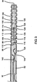
図3に最も良く示されるように、薄板90の下側は、燃料電池の動作中に冷却剤が通過する複数のチャネル112をその間に定める複数の畝110を含む。図3に示されるように、冷却剤チャネル112は、各ランド98の下に重なり、反応ガス溝100は、各畝110の下に重なる。代替として、薄板90は、フラットであることができ、流れ場は、金属の別個の薄板で形成される。金属薄板92は、薄板90と同様である。図2には、薄板92の内側面114(すなわち、冷却剤側)が示されている。
As best shown in FIG. 3, the underside of the
この点で、冷却剤がバイポーラプレートの一方の側120から他方122に流れる複数のチャネル118をその間に定める複数の畝116が示されている。薄板90と同様、図3に最も良く示されるように、薄板92の外側面は、反応ガスが通過する複数の溝128を定める複数のランド126をその上に有する作用面124を有する。内部金属スペーサ薄板94は、外部薄板90、92の間に位置付けられ、複数の開口130をその中に含み、複数の開口130は、薄板92のチャネル118と薄板90のチャネル112の間を冷却剤が流れることを可能にし、それによって、層流境界層を壊し、外部薄板90、92それぞれの内側面142、144との熱交換を向上させる乱流をもたらす
スペーサ薄板94は、第1の薄板90と第2の薄板92の間に位置付けられ、第1の薄板90上の畝110と第2の薄板92上の畝116は、(例えば、図4に示されるろう付けまたは接着剤などの接着層136によって)スペーサ薄板94に結合される。当業者であれば理解されるように、本発明の集電板は、例えば、流れ場の形状、流体送出マニホールドの数、および冷却剤循環システムなどの設計において、上で説明されたものとは異なることができるが、集電板の表面および本体を通る電流の導電率の関数は、すべての設計で同様に振舞う。
In this regard, a plurality of
ステンレス鋼は、一般に、最少で9%のクロムを含む鉄−クロム合金として定義される。その他の第二鉄、マルテンサイト、またはオーステナイト合金が、PEM燃料電池で使用されることが企図されている。クロム(すなわち少なくとも16重量%)、ニッケル(すなわち少なくとも10重量%)、およびモリブデン(すなわち少なくとも3重量%)が豊富なステンレス鋼は、それらの相対的に高いバルク導電性および表面の不活性化(すなわち、金属酸化物)層によって提供される耐食性のため、燃料電池内で使用するのに特に望ましい金属である。燃料電池スタックの容積および重量電力密度を増大させるために、薄いステンレス鋼プレートが使用され得る。さらに、ステンレス鋼材料は、その他の多くの代替導電性金属よりも相対的に高い強度、物理的耐久性、および保護被覆による接着性を有し、また廉価である。しかし、表面の酸化物層は、基板の電気接触抵抗を増大させ、それが、電気接触要素または集電板としてのその独立使用を以前は妨げていた。さらに、その他の多くの相対的に軽量の金属(例えば、アルミニウムおよびマグネシウム)は、腐食攻撃を受けやすく、そのような腐食感受性および同様の酸化傾向に鑑みて、様々な保護被覆が、金属基板のために使用される。 Stainless steel is generally defined as an iron-chromium alloy containing a minimum of 9% chromium. Other ferric, martensitic, or austenitic alloys are contemplated for use in PEM fuel cells. Stainless steels rich in chromium (ie, at least 16% by weight), nickel (ie, at least 10% by weight), and molybdenum (ie, at least 3% by weight) have their relatively high bulk conductivity and surface deactivation ( That is, it is a particularly desirable metal for use in fuel cells because of the corrosion resistance provided by the metal oxide) layer. Thin stainless steel plates can be used to increase the volume and weight power density of the fuel cell stack. In addition, stainless steel materials have relatively high strength, physical durability, and adhesion due to protective coatings, and are less expensive than many other alternative conductive metals. However, the surface oxide layer increases the electrical contact resistance of the substrate, which previously prevented its independent use as an electrical contact element or current collector. In addition, many other relatively light metals (eg, aluminum and magnesium) are susceptible to corrosion attack, and in view of such corrosion susceptibility and similar oxidation tendency, various protective coatings can be applied to metal substrates. Used for.
したがって、腐食を受けやすい金属から作成される導電要素または集電板は、低い接触抵抗と、腐食および酸化攻撃に耐える能力とを与えるように処理される。そのような処理は、以前は燃料電池で実際に使用するには電気接触抵抗があまりにも高かったステンレス鋼などの金属の使用を可能にする。したがって、好ましい実施形態にとって、金属基板は、鉄、クロム、ニッケル、およびモリブデンを含む合金である、例えば、316L(UNS S31603)などのステンレス鋼である。導電要素は、好ましくは、それを腐食因子から物理的に保護して、金属基板の表面における不活性化層の再形成を防止することによって、さらなる腐食/不活性化から保護される。図4に示されるように、導電要素(例えば、バイポーラプレート88)は、第1の薄板90の第1の面96および第2の薄板92の第2の面124の両面について金属基板140を覆う保護被覆138を有する。さらに、保護被覆138は、冷却剤による腐食酸化攻撃から基板140を保護するため、第1の薄板90の内部の第1の面142および第2の薄板92の第2の面144にも施される。実用上の観点からは、ステンレス鋼またはチタンが利用される場合、バイポーラプレートの内部または冷却剤通路を被覆する必要はない。保護被覆138は、処理環境および燃料電池自体に広く存在する腐食因子から導電要素を隔離するための実用的な方法である。したがって、金属と反応して各面を非活動化/不活性化する腐食因子から、下にある金属基板140が保護されるように、保護被覆138が、導電要素88の伝導領域および腐食を受けやすい領域(例えば、面96、124、142、144)に施されるのが好ましい。したがって、選択領域は、導電要素を横切る伝導通路を形成する伝導領域のみを含むことができ、またはそのような領域は、基板の全表面と一致することができる。
Thus, conductive elements or current collector plates made from metals that are susceptible to corrosion are treated to provide low contact resistance and the ability to withstand corrosion and oxidative attack. Such a process allows the use of metals such as stainless steel, which previously had too high electrical contact resistance for practical use in fuel cells. Thus, for a preferred embodiment, the metal substrate is stainless steel, such as 316L (UNS S31603), which is an alloy comprising iron, chromium, nickel, and molybdenum. The conductive element is preferably protected from further corrosion / deactivation by physically protecting it from corrosion factors and preventing re-formation of the passivation layer on the surface of the metal substrate. As shown in FIG. 4, the conductive element (eg, bipolar plate 88) covers the
保護被覆138は、本発明の譲受人に譲渡された、「Corrosion Resistant PEM Fuel Cell」と題する米国特許第6372376号に開示されているような様々な形態をとることができ、同特許の開示は、参照により本明細書に組み込まれる。保護被覆138は、好ましくは、下にある金属基板140を腐食因子への暴露から保護する耐食導電被覆である。より具体的には、保護被覆138は、好ましくは、約50オーム−cm2(Ω−cm2)より小さい界面電気接触抵抗を有し、耐酸性抗酸化ポリマーマトリックスの全体に拡散された複数の(すなわち約50ミクロンまたは約50ミクロン未満程度の)抗酸化酸不溶導電粒子を含み、ポリマーは、粒子を一緒に結合し、金属基板140の表面にそれらを保持する。被覆は、たかだか約50オーム−cm2の全界面電気接触抵抗を生み出すために十分な導電性充填粒子を含み、被覆の組成、抵抗率、および結着性に応じて、約2ミクロンから約75ミクロン、好ましくは、2から30ミクロンの間の厚みを有する。スタック内における抵抗損を最小化するには、より薄い被覆(すなわち、約15〜25ミクロン)が最も好ましい。腐食因子の浸透から下にある金属基板140の表面を保護するには、不浸透性の保護被覆138が好ましい。
The
好ましくは、導電性充填粒子は、金、白金、黒鉛、炭素、ニッケル、導電性ホウ化、窒化、および炭化金属(例えば、窒化チタン、炭化チタン、二ホウ化チタン)、クロムおよび/またはパラジウム混合チタン、ニオビウム、ロジウム、希土類金属、ならびにその他の貴金属からなる群から選択される。最も好ましくは、粒子は、炭素または黒鉛(すなわち、六方晶炭素)を含む。粒子は、粒子の密度および導電率に応じて、被覆の様々な重量パーセンテージを構成する(すなわち、導電率が高く、密度が低い粒子は、より低い重量パーセンテージで使用され得る)。炭素/黒鉛含有被覆は、典型的には、25重量パーセントの炭素/黒鉛粒子を含む。ポリマーマトリックスは、薄い接着性薄膜に形成され得る、燃料電池の悪条件の酸化および酸環境に耐え得る任意のポリマーを含む。したがって、とりわけ、エポキシ、シリコーン、ポリアミドイミド、ポリエーテルイミド、ポリフェノール、フルロエラストマ、ポリエステル、フェノキシフェノール、エポキシフェノール、アクリル、およびウレタンのようなポリマーが、有用であると見られている。熱硬化性および熱可塑性ポリマーの両方が、不浸透性被覆を生成するのに適している。 Preferably, the conductive filler particles are gold, platinum, graphite, carbon, nickel, conductive boride, nitride, and metal carbide (eg, titanium nitride, titanium carbide, titanium diboride), chromium and / or palladium mixed It is selected from the group consisting of titanium, niobium, rhodium, rare earth metals, and other noble metals. Most preferably, the particles comprise carbon or graphite (ie hexagonal carbon). The particles constitute various weight percentages of the coating, depending on the density and conductivity of the particles (ie, particles with high conductivity and low density can be used at lower weight percentages). The carbon / graphite containing coating typically comprises 25 weight percent carbon / graphite particles. The polymer matrix comprises any polymer that can withstand the adverse conditions of fuel cell oxidization and acid environments that can be formed into a thin adhesive film. Thus, inter alia, polymers such as epoxies, silicones, polyamideimides, polyetherimides, polyphenols, fluoroelastomers, polyesters, phenoxyphenols, epoxyphenols, acrylics, and urethanes have been found useful. Both thermosetting and thermoplastic polymers are suitable for producing an impermeable coating.
導電ポリマー被覆138は、基板金属140に直接施されることができ、その上で乾燥/硬化させることができる。被覆138は、様々な方法で施されることができ、そのような方法の例は、Fronkらの米国特許第6372376号に記載されており、(1)電気泳動法、(2)はけ塗り、吹き付け、もしくは塗布、または(3)貼り合わせを含むことができる。被覆は、コイル被覆など連続製造工程で使用するために適合され得る。
The
上で述べられたように、バイポーラプレート88は、レーザ溶接などの集束放射を用いて薄板90、92の部分を互いに溶接することにより薄板90、92を互いに結合することによって作成される。例えば、バイポーラプレート88のプレート90の第1の面96の平面図が、破線150によって示される一緒にレーザ溶接されるバイポーラプレート88のいくつかの領域と共に図5に示されており、被覆138で覆われるバイポーラプレート88の部分は、陰が付けられている。溶接線150は、バイポーラプレート88を溶接するための可能な位置を表していること、バイポーラプレート88を溶接する正確な位置は、薄板90、92の設計、およびバイポーラプレート88を形成するスペーサ薄板94などのその他の構成要素の追加に応じて変化することを理解されたい。
As stated above, the
互いに溶接されるバイポーラプレート88の領域150は、図6Aに示されるバイポーラプレート88の拡大部分など、被覆138で覆われる領域を含む。第1および第2の薄板90、92を互いに溶接するとき、集束放射が、集束放射と接触する第1および第2の薄板90、92の部分を溶融させる。集束放射が取り除かれると、第1および第2の薄板90、92の溶融部分は、凝固し、それによって、図6Aおよび図6Bに示された融着部分154に示されるように、互いに融着される。加えて、図6Bから最も良く理解されるように、集束放射は、集束放射と直接接触する、バイポーラプレート88の融着部分154に隣接した被覆138の部分の除去も行う。
バイポーラプレート88の表面からの被覆138の除去は、以下の実施例1で説明されるように、第1および第2の薄板90、92の耐食性に著しい影響を与えない。すなわち、被覆138が有機被覆であり、バイポーラプレート88がステンレス鋼薄板90、92から作成される場合、集束放射を用いて第1および第2の薄板90、92を互いに溶接している最中の、第1および第2の薄板90、92との被覆138の有機成分の接触は、ステンレス鋼薄板の耐食性に有害な影響を与える程度までステンレス鋼を過敏化しない。この能力は、第1および第2の薄板90、92が、互いに溶接されてバイポーラプレート88を形成する前に、被覆138で覆われることを可能にする。この能力は、第1および第2の薄板90、92が、事前被覆されたストック金属ロールから形成され得るという著しい利点を提供する。言い換えると、第1および第2の薄板90、92がそれから形成されるストック金属は、コイル被覆などのストック金属材料の製造中またはその後のある時点で、被覆138によって覆われることができる。その後、第1および第2の薄板90、92は、ストック被覆薄板材料から、スタンピング、電気鋳造、または薄板金属を成形するためのその他の任意の従来方法などによって、経済的かつ連続的な方法で形成されることができ、その後、互いに隣り合わせて位置付けられ、バイポーラプレート88を形成するために互いに溶接されることができる。したがって、本発明は、燃料電池で使用されるバイポーラプレートを製造する経済的かつ効率的な方法を企図している。
Removal of the
望ましければ、第1および第2の薄板90、92を互いに溶接した後、図7Aに示されるように、第2の保護被覆160が、被覆138の除去領域上に施されることができる。図7Bに示されるような第2の被覆160の適用は、薄板90、92の融着部分154が第2の保護被覆160によって覆われ、保護されるようにする。第2の保護被覆160は、様々な方法で施され得る。例えば、第2の保護被覆160は、示されたような吹き付け、はけ塗り、または塗布によって施され得る。好ましくは、第2の被覆160は、被覆138と同じである。しかし、第2の被覆160は、被覆138で使用されたものとは異なる保護被覆であり得ることを理解されたい。さらに、望ましければ、第2の被覆160は、バイポーラプレート88の溶接部分の離散した領域に選択的に施され得る。
If desired, after the first and
バイポーラプレート88を形成するための集束放射による第1および第2の薄板90、92の溶接は、様々な形態をとることができる。例えば、Nd−YAGまたはCO2レーザなどのレーザ溶接が、第1および第2の薄板90、92を互いに溶接するために使用され得る。選択されるレーザの具体的なタイプは、第1および第2の薄板90、92を互いに溶接するのに必要とされるスペクトル範囲、エネルギー密度、およびビーム直径に依存する。加えて、バイポーラプレート88を形成するとき、バイポーラプレート88のその他の構成要素も、第1および第2の薄板90、92と一緒に溶接されることができる。例えば、スペーサ薄板94の部分が、第1および第2の薄板90、92が互いに溶接される領域内に存在することができ、集束放射ビームによって溶融され、バイポーラプレート88の融着部分の一部を形成することができる。第1および第2の薄板90、92と一緒に溶接されるバイポーラプレート88のその他の構成要素は、スペーサ薄板94に限定されない。その他の構成要素は、バイポーラプレート88の内部または外部に固定的に結合されることが必要とされ得るセンサ、バルブのような物を含むことができる。隣り合うバイポーラプレート88をその間に配置されるMEAを介して互いに溶接することすら可能なことがある。
The welding of the first and second
導電炭素被覆ステンレス鋼プレートへの様々なレーザ溶接が、ASTM標準による断面検査およびシュウ酸エッチングによって、ならびにウッドコック腐食試験によって試験された。断面検査は、ステンレス鋼プレートで生じる過敏化の証拠を示さなかった。ウッドコック腐食試験では、溶接への攻撃がいくつか行われたが、ステンレス鋼プレートで生じる有害な過敏化の証拠を示さなかった。ステンレス鋼プレートの試験の詳細が、以下の表に示されている。 Various laser welds to conductive carbon coated stainless steel plates were tested by cross section inspection and oxalic acid etching according to ASTM standards, and by Woodcock corrosion tests. Cross-sectional inspection showed no evidence of sensitization occurring with stainless steel plates. The Woodcock corrosion test made several attacks on the weld, but showed no evidence of the detrimental sensitization that occurs with stainless steel plates. Details of the stainless steel plate test are shown in the table below.

したがって、本発明は、後に互いに溶接されてバイポーラプレートを形成する薄板を事前被覆されたストック材料を使用して形成することによって、バイポーラプレート88が経済的かつ効率的に生産されることを可能にする。溶接前の薄膜上における被覆の存在は、十分なレベルの耐食性を維持する薄板の能力に影響を与えない。被覆は、有機および/または無機であることができ、薄板は、ステンレス鋼および上で説明されたような様々なその他の材料を含むことができる。加えて、被覆は、プレート90、92の外側面(電流伝導面)だけに配置されることができ、かつ/またはプレートの内側面および外側面の両方に配置されることができる。加えて、様々な被覆が施された3以上の層または金属プレートが、本発明の原理に従って、一緒に溶接されることができる。加えて、シールまたはガスケット(図示されず)が、溶接領域の上のバイポーラプレートの1つまたは複数の面に位置付けられ、接着剤またはオーバモールディングによってプレートに結合されることができる。
Thus, the present invention allows the
したがって、本発明の説明は、本質的に例示的なものに過ぎず、本発明の主旨から逸脱しない変形は、本発明の範囲内にあることが意図されている。そのような変形は、本発明の主旨および範囲からの逸脱と見なされるべきではない。 Accordingly, the description of the invention is merely exemplary in nature and, thus, variations that do not depart from the gist of the invention are intended to be within the scope of the invention. Such variations are not to be regarded as a departure from the spirit and scope of the invention.
図6Bは線6B−6Bに沿った図6Aのバイポーラプレートのレーザ溶接領域の断面図である。
図7Bは線7B−7Bに沿った図7Aの再被覆レーザ溶接領域の断面図である。
FIG. 7B is a cross-sectional view of the recoat laser welding region of FIG. 7A along
Claims (20)
(a)第1の導電有機被覆が施された前記第1の金属部材を、第2の金属部材の隣に位置付けるステップと、
(b)前記隣り合う金属部材を結合するためにレーザを使用して前記隣り合う金属部材の一部分を溶融させるステップと、
(c)前記隣り合う金属部材の前記溶融させた部分を凝固させて、それによって、前記隣り合う金属部材を融着するステップとを含み、
(b)が、前記隣り合う金属部材の前記溶融部分に隣接する前記第1の導電有機被覆の部分を同時に除去するステップを含む、方法。A method for making a bipolar plate having at least two metal members joined together, at least one of which is provided with a conductive organic coating,
(A) positioning the first metal member provided with the first conductive organic coating next to the second metal member;
(B) melting a portion of the adjacent metal members using a laser to join the adjacent metal members;
(C) solidifying the melted portion of the adjacent metal member, thereby fusing the adjacent metal member ;
(B) comprising simultaneously removing a portion of the first conductive organic coating adjacent to the molten portion of the adjacent metal member .
(a)一方の表面の少なくとも一部分に導電有機被覆が施された第1の金属プレートを、第2の金属プレートの隣に、前記被覆部分が前記第2のプレートの方とは反対を向くように位置付けるステップと、
(b)前記被覆の部分を含む前記隣り合うプレートの部分にレーザを当て、それによって、前記被覆の前記部分を同時に除去し、前記隣り合うプレートの前記部分を溶融させるステップと、
(c)前記レーザを当てることを止めるステップと、
(d)前記溶融された部分を凝固し、それによって、前記隣り合うプレートを融着させ、それによって、前記バイポーラプレートの1つを形成するステップとを含む、方法。A method for making a fuel cell stack having a metal bipolar plate with internal flow passages, comprising:
(A) A first metal plate having a conductive organic coating applied to at least a part of one surface thereof is placed next to the second metal plate so that the coating portion faces away from the second plate. A step positioned at
(B) applying a laser to a portion of the adjacent plate that includes the portion of the coating, thereby simultaneously removing the portion of the coating and melting the portion of the adjacent plate;
(C) stopping applying the laser ;
(D) solidifying the melted portion , thereby fusing the adjacent plates , thereby forming one of the bipolar plates.
金属材料の前記被覆薄板から前記第1のプレートを形成するステップとを含む、請求項5に記載の方法。Applying the coating to a portion of the surface of the sheet of metal material;
And forming said first plate from said coated sheet of metallic material, The method of claim 5.
(a)が、前記第2のプレートを、前記第1のプレートの隣に、前記第2のプレートの前記被覆面が前記第1のプレートの方とは反対を向くように位置付けるステップを含み、
(b)が、前記レーザを用いて前記第2のプレートの前記被覆の部分を除去するステップを含む、請求項5に記載の方法。At least a portion of one surface of the second plate is coated with the coating;
(A) positioning the second plate next to the first plate such that the covering surface of the second plate faces away from the first plate;
The method of claim 5 , wherein (b) comprises removing the portion of the coating of the second plate using the laser .
(a)前記バイポーラプレートの第1の金属プレートに導電有機被覆を施すステップと、
(b)前記導電有機被覆を含む前記第1のプレートを、前記バイポーラプレートの第2の金属プレートの隣に位置付けるステップと、
(c)前記被覆の部分を含む前記隣り合うプレートの部分にレーザを当て、それによって、前記被覆の前記部分を同時に除去し、前記隣り合うプレートの前記部分を溶融させるステップと、
(d)前記レーザを当てることを止めるステップと、
(e)前記溶融された部分を凝固および融着させ、それによって、前記バイポーラプレートを形成するステップとを含む、方法。A method of making a bipolar plate for a fuel cell stack,
(A) applying a conductive organic coating to the first metal plate of the bipolar plate;
(B) positioning the first plate including the conductive organic coating next to a second metal plate of the bipolar plate;
(C) applying a laser to a portion of the adjacent plate that includes the portion of the coating, thereby simultaneously removing the portion of the coating and melting the portion of the adjacent plate;
(D) stopping applying the laser ;
(E) solidifying and fusing the melted portion, thereby forming the bipolar plate.
金属材料の薄板の表面の部分に前記被覆を施すステップと、
金属材料の前記被覆薄板から前記第1のプレートを形成するステップとを含む、請求項15に記載の方法。(A)
Applying the coating to a portion of the surface of the sheet of metal material;
And forming said first plate from said coated sheet of metallic material, The method of claim 15.
(b)が、前記第1のプレートを、前記第2のプレートの隣に、前記第2のプレートの前記被覆面が前記第1のプレートの方とは反対を向くように位置付けるステップを含み、
(c)が、前記レーザを用いて前記第2のプレートの前記被覆の部分を除去するステップを含む、請求項15に記載の方法。At least a portion of one surface of the second plate is coated with the coating;
(B) includes positioning the first plate next to the second plate such that the covering surface of the second plate faces away from the first plate;
The method of claim 15 , wherein (c) comprises removing the portion of the coating of the second plate using the laser .
Applications Claiming Priority (3)
| Application Number | Priority Date | Filing Date | Title |
|---|---|---|---|
| US10/842,788 | 2004-05-11 | ||
| US10/842,788 US8089027B2 (en) | 2004-05-11 | 2004-05-11 | Laser welding of conductive coated metallic bipolar plates |
| PCT/US2005/014096 WO2005120764A2 (en) | 2004-05-11 | 2005-04-25 | Laser welding of conductive coated metallic bipolar plates |
Publications (2)
| Publication Number | Publication Date |
|---|---|
| JP2007537574A JP2007537574A (en) | 2007-12-20 |
| JP4966191B2 true JP4966191B2 (en) | 2012-07-04 |
Family
ID=35308421
Family Applications (1)
| Application Number | Title | Priority Date | Filing Date |
|---|---|---|---|
| JP2007513171A Expired - Fee Related JP4966191B2 (en) | 2004-05-11 | 2005-04-25 | Laser welding of conductive coated metal bipolar plates. |
Country Status (5)
| Country | Link |
|---|---|
| US (1) | US8089027B2 (en) |
| JP (1) | JP4966191B2 (en) |
| CN (1) | CN101094744B (en) |
| DE (1) | DE112005001058T5 (en) |
| WO (1) | WO2005120764A2 (en) |
Families Citing this family (32)
| Publication number | Priority date | Publication date | Assignee | Title |
|---|---|---|---|---|
| JP4469674B2 (en) * | 2004-07-15 | 2010-05-26 | 株式会社東芝 | Manufacturing method of flow channel structure |
| US7704626B2 (en) | 2004-07-29 | 2010-04-27 | Gm Global Technology Operations, Inc. | Isolated and insulated stack end unit inlet/outlet manifold headers |
| JP4830378B2 (en) * | 2005-07-13 | 2011-12-07 | トヨタ自動車株式会社 | Fuel cell and fuel cell manufacturing method |
| JP5343307B2 (en) | 2006-05-16 | 2013-11-13 | 日産自動車株式会社 | FUEL CELL STACK, FUEL CELL SEPARATOR, AND METHOD FOR PRODUCING THE SAME |
| FR2911219B1 (en) * | 2007-01-09 | 2009-05-15 | Conception Dev Michelin S A | BIPOLAR PLATE FOR FUEL CELL WITH POLYMERIC MEMBRANE |
| JP5205816B2 (en) * | 2007-05-30 | 2013-06-05 | 日産自動車株式会社 | Fuel cell |
| DE102007044634B4 (en) * | 2007-09-19 | 2009-09-10 | Zentrum für Sonnenenergie- und Wasserstoff-Forschung Baden-Württemberg Gemeinnützige Stiftung | High Temperature Polymer Electrolyte Membrane Fuel Cell (HT-PEMFC) including devices for cooling same |
| US20090136824A1 (en) * | 2007-11-26 | 2009-05-28 | Daido Tokushuko Kabushiki Kaisha | Metallic bipolar plate for fuel cells and method for manufacturing the same |
| US8405001B2 (en) | 2009-07-13 | 2013-03-26 | Illinois Tool Works Inc | Hybrid welding systems and devices |
| CN102581487B (en) * | 2012-02-16 | 2015-03-04 | 上海交通大学 | Laser weld-bonding method of bipolar plate of fuel cell |
| US8778567B1 (en) * | 2012-12-21 | 2014-07-15 | GM Global Technology Operations LLC | Unique pre-form design for two-step forming of stainless steel fuel cell bipolar plates |
| JP6020718B2 (en) * | 2013-05-16 | 2016-11-02 | 日産自動車株式会社 | Manufacturing apparatus and manufacturing method for fuel cell separator assembly |
| DE102013219010A1 (en) * | 2013-09-20 | 2015-03-26 | Volkswagen Ag | Functionalized membrane, functionalized bipolar plate and fuel cell |
| CN103878524B (en) * | 2014-03-28 | 2016-02-10 | 上海交通大学 | A kind of ultra-thin metal bipolar plate multistage clamping self adaptation fixture for laser welding |
| DE102015205295A1 (en) * | 2015-03-24 | 2016-09-29 | Volkswagen Ag | Bipolar plate assembly for fuel cell and manufacturing process |
| TWI624989B (en) * | 2016-12-14 | 2018-05-21 | 財團法人工業技術研究院 | Bipolar plate, fuel cell and fuel cell stack |
| FR3073324B1 (en) | 2017-11-08 | 2019-10-25 | Commissariat A L'energie Atomique Et Aux Energies Alternatives | METHOD USING A LASER FOR WELDING BETWEEN TWO METALLIC MATERIALS OR FOR POWDER FRITTAGE (S), APPLICATION TO THE PRODUCTION OF BIPOLAR PLATES FOR PEMFC CELLS |
| JP7010077B2 (en) * | 2018-03-13 | 2022-02-10 | トヨタ車体株式会社 | Method for manufacturing a fuel cell separator joint and a fuel cell separator joint |
| TWI645927B (en) * | 2018-03-23 | 2019-01-01 | 國立臺北科技大學 | Electroplating welding element and preparation method thereof |
| JP7020291B2 (en) * | 2018-05-23 | 2022-02-16 | トヨタ車体株式会社 | Method for manufacturing fuel cell separator and fuel cell separator |
| CN109777732B (en) * | 2019-01-17 | 2020-12-18 | 重庆大学 | Bipolar cell fusion instrument and control method thereof |
| DE102019202493A1 (en) | 2019-02-25 | 2020-08-27 | Audi Ag | Method for producing a bipolar plate strand, method for producing a bipolar plate and device for carrying out the method |
| US11465236B2 (en) | 2019-09-26 | 2022-10-11 | GM Global Technology Operations LLC | Intelligent non-autogenous metalworking systems and control logic with automated wire-to-beam alignment |
| CN111354956B (en) * | 2020-02-20 | 2021-04-27 | 浙江锋源氢能科技有限公司 | Anti-corrosion treatment method for welding wire of metal bipolar plate and metal bipolar plate |
| WO2021173828A1 (en) * | 2020-02-25 | 2021-09-02 | Platelet Biogenesis, Inc. | Systems and methods for forming a fluidic system |
| JP7322814B2 (en) * | 2020-05-26 | 2023-08-08 | トヨタ自動車株式会社 | Method for manufacturing fuel cell |
| DE102020122079A1 (en) | 2020-08-24 | 2022-02-24 | Audi Aktiengesellschaft | Method for producing a bipolar plate strand, method for producing a bipolar plate and device for carrying out the method |
| CN114614040A (en) * | 2020-12-09 | 2022-06-10 | 中国科学院大连化学物理研究所 | Interval cooling fuel cell stack |
| CN113422086A (en) * | 2021-07-23 | 2021-09-21 | 安泰环境工程技术有限公司 | Metal bipolar plate structure |
| US20230096327A1 (en) * | 2021-09-30 | 2023-03-30 | Nissan North America, Inc. | Bipolar plate for fuel cell stack |
| DE102022100187A1 (en) * | 2022-01-05 | 2023-07-06 | Trumpf Laser- Und Systemtechnik Gmbh | Process for laser welding a bipolar plate of a fuel cell, with a weld pool generated with several laser spots |
| CN115138970B (en) * | 2022-08-08 | 2023-10-10 | 大同新研氢能源科技有限公司 | Fuel cell bipolar plate and welding method thereof |
Family Cites Families (21)
| Publication number | Priority date | Publication date | Assignee | Title |
|---|---|---|---|---|
| US3522095A (en) * | 1965-01-14 | 1970-07-28 | Gen Electric | Laminar membrane fuel cells and processes for their manufacture |
| WO1995024279A1 (en) * | 1994-03-10 | 1995-09-14 | Ishikawa, Toshiharu | Film removing device |
| RU2174728C2 (en) * | 1994-10-12 | 2001-10-10 | Х Пауэр Корпорейшн | Fuel cell using integrated plate technology for liquid-distribution |
| JPH09283920A (en) * | 1996-04-15 | 1997-10-31 | Omron Corp | Component mounting board and its manufacture |
| JP3135858B2 (en) * | 1997-03-21 | 2001-02-19 | 東芝電子エンジニアリング株式会社 | Laser processing apparatus and method |
| JPH1197039A (en) * | 1997-09-17 | 1999-04-09 | Yoyu Tansanengata Nenryo Denchi Hatsuden System Gijutsu Kenkyu Kumiai | Layered fuel cell and manufacture of the same |
| JP4391609B2 (en) * | 1998-09-30 | 2009-12-24 | 株式会社ジーエス・ユアサコーポレーション | Non-aqueous electrolyte secondary battery for battery pack |
| EP1009051A2 (en) * | 1998-12-08 | 2000-06-14 | General Motors Corporation | Liquid cooled bipolar plate consisting of glued plates for PEM fuel cells |
| JP2000208153A (en) * | 1999-01-18 | 2000-07-28 | Fuji Electric Co Ltd | Solid polymer electrolyte fuel cell |
| US6372376B1 (en) * | 1999-12-07 | 2002-04-16 | General Motors Corporation | Corrosion resistant PEM fuel cell |
| US6828054B2 (en) * | 2000-02-11 | 2004-12-07 | The Texas A&M University System | Electronically conducting fuel cell component with directly bonded layers and method for making the same |
| DE10017200A1 (en) * | 2000-04-06 | 2001-10-18 | Dornier Gmbh | Electrically conductive multiple layers for bipolar plates in fuel cells |
| DE10063720A1 (en) * | 2000-12-20 | 2002-07-11 | Siemens Ag | Low-temperature fuel cell |
| CN1416184A (en) * | 2001-11-01 | 2003-05-07 | 哈尔滨工业大学 | Metal compound bipolar plate of fuel cell with proton exchange film |
| JP4469541B2 (en) * | 2002-03-28 | 2010-05-26 | 三菱樹脂株式会社 | Fuel cell separator and method for producing the same |
| DE10221951B4 (en) | 2002-05-13 | 2004-04-22 | Reinz-Dichtungs-Gmbh & Co. Kg | Bipolar plate and method for its production and device for carrying out the method |
| JP2004111079A (en) * | 2002-09-13 | 2004-04-08 | Nissei Corp | Metal separator for fuel cell and solid polymer type fuel cell using the same |
| US7009136B2 (en) * | 2002-10-09 | 2006-03-07 | General Motors Corporation | Method of fabricating a bipolar plate assembly |
| DE10261482A1 (en) * | 2002-12-23 | 2004-07-01 | Basf Ag | Fuel cell module for polymer electrolyte membrane fuel cell stacks used e.g. in vehicles comprises a bipolar plate and a membrane-electrode unit |
| DE10301052B4 (en) | 2003-01-13 | 2008-04-03 | Daimler Ag | Bipolar plate unit, electrochemical cell and means for sealing |
| US6887610B2 (en) * | 2003-01-21 | 2005-05-03 | General Motors Corporation | Joining of bipolar plates in proton exchange membrane fuel cell stacks |
-
2004
- 2004-05-11 US US10/842,788 patent/US8089027B2/en active Active
-
2005
- 2005-04-25 JP JP2007513171A patent/JP4966191B2/en not_active Expired - Fee Related
- 2005-04-25 CN CN2005800226030A patent/CN101094744B/en active Active
- 2005-04-25 DE DE112005001058T patent/DE112005001058T5/en not_active Withdrawn
- 2005-04-25 WO PCT/US2005/014096 patent/WO2005120764A2/en active Application Filing
Also Published As
| Publication number | Publication date |
|---|---|
| JP2007537574A (en) | 2007-12-20 |
| DE112005001058T5 (en) | 2007-04-19 |
| US8089027B2 (en) | 2012-01-03 |
| CN101094744B (en) | 2010-04-21 |
| WO2005120764A2 (en) | 2005-12-22 |
| WO2005120764A3 (en) | 2006-04-13 |
| CN101094744A (en) | 2007-12-26 |
| US20050252892A1 (en) | 2005-11-17 |
Similar Documents
| Publication | Publication Date | Title |
|---|---|---|
| JP4966191B2 (en) | Laser welding of conductive coated metal bipolar plates. | |
| EP2025027B1 (en) | Fuel cell stack and method of producing its separator plates | |
| JP4800942B2 (en) | Adhesive joint for metal bipolar plate | |
| US8568940B2 (en) | Joining bipolar plates using localized electrical nodes | |
| EP1009051A2 (en) | Liquid cooled bipolar plate consisting of glued plates for PEM fuel cells | |
| US5776624A (en) | Brazed bipolar plates for PEM fuel cells | |
| JP5076360B2 (en) | Fuel cell stack and manufacturing method thereof | |
| US6866958B2 (en) | Ultra-low loadings of Au for stainless steel bipolar plates | |
| US7344798B2 (en) | Low contact resistance bonding method for bipolar plates in a pem fuel cell | |
| US8835079B2 (en) | Fuel cell separator plate surface treatment by laser ablation | |
| EP1249050B1 (en) | Bipolar separator plate with improved wet seals | |
| CA2652067C (en) | Fuel cell, fuel cell stack and method of manufacturing the same | |
| JP4627406B2 (en) | Separator and fuel cell | |
| JP2007220403A (en) | Separator for fuel cell, fuel cell stack, and its manufacturing method | |
| JP2012212684A (en) | Fuel cell stack and method of manufacturing the same | |
| US20240039010A1 (en) | Fuel cell and manufacturing method of fuel cell |
Legal Events
| Date | Code | Title | Description |
|---|---|---|---|
| A131 | Notification of reasons for refusal |
Free format text: JAPANESE INTERMEDIATE CODE: A131 Effective date: 20100520 |
|
| A521 | Request for written amendment filed |
Free format text: JAPANESE INTERMEDIATE CODE: A523 Effective date: 20100820 |
|
| A131 | Notification of reasons for refusal |
Free format text: JAPANESE INTERMEDIATE CODE: A131 Effective date: 20110401 |
|
| RD04 | Notification of resignation of power of attorney |
Free format text: JAPANESE INTERMEDIATE CODE: A7424 Effective date: 20110912 |
|
| TRDD | Decision of grant or rejection written | ||
| A01 | Written decision to grant a patent or to grant a registration (utility model) |
Free format text: JAPANESE INTERMEDIATE CODE: A01 Effective date: 20120302 |
|
| A01 | Written decision to grant a patent or to grant a registration (utility model) |
Free format text: JAPANESE INTERMEDIATE CODE: A01 |
|
| A61 | First payment of annual fees (during grant procedure) |
Free format text: JAPANESE INTERMEDIATE CODE: A61 Effective date: 20120330 |
|
| R150 | Certificate of patent or registration of utility model |
Free format text: JAPANESE INTERMEDIATE CODE: R150 |
|
| FPAY | Renewal fee payment (event date is renewal date of database) |
Free format text: PAYMENT UNTIL: 20150406 Year of fee payment: 3 |
|
| R250 | Receipt of annual fees |
Free format text: JAPANESE INTERMEDIATE CODE: R250 |
|
| R250 | Receipt of annual fees |
Free format text: JAPANESE INTERMEDIATE CODE: R250 |
|
| R250 | Receipt of annual fees |
Free format text: JAPANESE INTERMEDIATE CODE: R250 |
|
| LAPS | Cancellation because of no payment of annual fees |