EP2025027B1 - Fuel cell stack and method of producing its separator plates - Google Patents
Fuel cell stack and method of producing its separator plates Download PDFInfo
- Publication number
- EP2025027B1 EP2025027B1 EP07734565A EP07734565A EP2025027B1 EP 2025027 B1 EP2025027 B1 EP 2025027B1 EP 07734565 A EP07734565 A EP 07734565A EP 07734565 A EP07734565 A EP 07734565A EP 2025027 B1 EP2025027 B1 EP 2025027B1
- Authority
- EP
- European Patent Office
- Prior art keywords
- separator
- portions
- corrosion
- fuel cell
- welded portions
- Prior art date
- Legal status (The legal status is an assumption and is not a legal conclusion. Google has not performed a legal analysis and makes no representation as to the accuracy of the status listed.)
- Expired - Fee Related
Links
Images


Classifications
-
- H—ELECTRICITY
- H01—ELECTRIC ELEMENTS
- H01M—PROCESSES OR MEANS, e.g. BATTERIES, FOR THE DIRECT CONVERSION OF CHEMICAL ENERGY INTO ELECTRICAL ENERGY
- H01M8/00—Fuel cells; Manufacture thereof
- H01M8/10—Fuel cells with solid electrolytes
- H01M8/1004—Fuel cells with solid electrolytes characterised by membrane-electrode assemblies [MEA]
-
- B—PERFORMING OPERATIONS; TRANSPORTING
- B23—MACHINE TOOLS; METAL-WORKING NOT OTHERWISE PROVIDED FOR
- B23K—SOLDERING OR UNSOLDERING; WELDING; CLADDING OR PLATING BY SOLDERING OR WELDING; CUTTING BY APPLYING HEAT LOCALLY, e.g. FLAME CUTTING; WORKING BY LASER BEAM
- B23K26/00—Working by laser beam, e.g. welding, cutting or boring
- B23K26/20—Bonding
- B23K26/21—Bonding by welding
- B23K26/24—Seam welding
- B23K26/244—Overlap seam welding
-
- H—ELECTRICITY
- H01—ELECTRIC ELEMENTS
- H01M—PROCESSES OR MEANS, e.g. BATTERIES, FOR THE DIRECT CONVERSION OF CHEMICAL ENERGY INTO ELECTRICAL ENERGY
- H01M8/00—Fuel cells; Manufacture thereof
- H01M8/02—Details
- H01M8/0202—Collectors; Separators, e.g. bipolar separators; Interconnectors
- H01M8/0204—Non-porous and characterised by the material
- H01M8/0206—Metals or alloys
- H01M8/0208—Alloys
- H01M8/021—Alloys based on iron
-
- H—ELECTRICITY
- H01—ELECTRIC ELEMENTS
- H01M—PROCESSES OR MEANS, e.g. BATTERIES, FOR THE DIRECT CONVERSION OF CHEMICAL ENERGY INTO ELECTRICAL ENERGY
- H01M8/00—Fuel cells; Manufacture thereof
- H01M8/02—Details
- H01M8/0202—Collectors; Separators, e.g. bipolar separators; Interconnectors
- H01M8/0204—Non-porous and characterised by the material
- H01M8/0223—Composites
- H01M8/0228—Composites in the form of layered or coated products
-
- H—ELECTRICITY
- H01—ELECTRIC ELEMENTS
- H01M—PROCESSES OR MEANS, e.g. BATTERIES, FOR THE DIRECT CONVERSION OF CHEMICAL ENERGY INTO ELECTRICAL ENERGY
- H01M8/00—Fuel cells; Manufacture thereof
- H01M8/02—Details
- H01M8/0202—Collectors; Separators, e.g. bipolar separators; Interconnectors
- H01M8/0247—Collectors; Separators, e.g. bipolar separators; Interconnectors characterised by the form
- H01M8/0254—Collectors; Separators, e.g. bipolar separators; Interconnectors characterised by the form corrugated or undulated
-
- H—ELECTRICITY
- H01—ELECTRIC ELEMENTS
- H01M—PROCESSES OR MEANS, e.g. BATTERIES, FOR THE DIRECT CONVERSION OF CHEMICAL ENERGY INTO ELECTRICAL ENERGY
- H01M8/00—Fuel cells; Manufacture thereof
- H01M8/02—Details
- H01M8/0202—Collectors; Separators, e.g. bipolar separators; Interconnectors
- H01M8/0258—Collectors; Separators, e.g. bipolar separators; Interconnectors characterised by the configuration of channels, e.g. by the flow field of the reactant or coolant
-
- H—ELECTRICITY
- H01—ELECTRIC ELEMENTS
- H01M—PROCESSES OR MEANS, e.g. BATTERIES, FOR THE DIRECT CONVERSION OF CHEMICAL ENERGY INTO ELECTRICAL ENERGY
- H01M8/00—Fuel cells; Manufacture thereof
- H01M8/02—Details
- H01M8/0202—Collectors; Separators, e.g. bipolar separators; Interconnectors
- H01M8/0267—Collectors; Separators, e.g. bipolar separators; Interconnectors having heating or cooling means, e.g. heaters or coolant flow channels
-
- H—ELECTRICITY
- H01—ELECTRIC ELEMENTS
- H01M—PROCESSES OR MEANS, e.g. BATTERIES, FOR THE DIRECT CONVERSION OF CHEMICAL ENERGY INTO ELECTRICAL ENERGY
- H01M8/00—Fuel cells; Manufacture thereof
- H01M8/02—Details
- H01M8/0297—Arrangements for joining electrodes, reservoir layers, heat exchange units or bipolar separators to each other
-
- H—ELECTRICITY
- H01—ELECTRIC ELEMENTS
- H01M—PROCESSES OR MEANS, e.g. BATTERIES, FOR THE DIRECT CONVERSION OF CHEMICAL ENERGY INTO ELECTRICAL ENERGY
- H01M8/00—Fuel cells; Manufacture thereof
- H01M8/24—Grouping of fuel cells, e.g. stacking of fuel cells
- H01M8/2404—Processes or apparatus for grouping fuel cells
-
- H—ELECTRICITY
- H01—ELECTRIC ELEMENTS
- H01M—PROCESSES OR MEANS, e.g. BATTERIES, FOR THE DIRECT CONVERSION OF CHEMICAL ENERGY INTO ELECTRICAL ENERGY
- H01M8/00—Fuel cells; Manufacture thereof
- H01M8/24—Grouping of fuel cells, e.g. stacking of fuel cells
- H01M8/241—Grouping of fuel cells, e.g. stacking of fuel cells with solid or matrix-supported electrolytes
-
- H—ELECTRICITY
- H01—ELECTRIC ELEMENTS
- H01M—PROCESSES OR MEANS, e.g. BATTERIES, FOR THE DIRECT CONVERSION OF CHEMICAL ENERGY INTO ELECTRICAL ENERGY
- H01M8/00—Fuel cells; Manufacture thereof
- H01M8/24—Grouping of fuel cells, e.g. stacking of fuel cells
- H01M8/2457—Grouping of fuel cells, e.g. stacking of fuel cells with both reactants being gaseous or vaporised
-
- H—ELECTRICITY
- H01—ELECTRIC ELEMENTS
- H01M—PROCESSES OR MEANS, e.g. BATTERIES, FOR THE DIRECT CONVERSION OF CHEMICAL ENERGY INTO ELECTRICAL ENERGY
- H01M8/00—Fuel cells; Manufacture thereof
- H01M8/24—Grouping of fuel cells, e.g. stacking of fuel cells
- H01M8/2465—Details of groupings of fuel cells
- H01M8/2483—Details of groupings of fuel cells characterised by internal manifolds
-
- B—PERFORMING OPERATIONS; TRANSPORTING
- B23—MACHINE TOOLS; METAL-WORKING NOT OTHERWISE PROVIDED FOR
- B23K—SOLDERING OR UNSOLDERING; WELDING; CLADDING OR PLATING BY SOLDERING OR WELDING; CUTTING BY APPLYING HEAT LOCALLY, e.g. FLAME CUTTING; WORKING BY LASER BEAM
- B23K2101/00—Articles made by soldering, welding or cutting
- B23K2101/34—Coated articles, e.g. plated or painted; Surface treated articles
-
- B—PERFORMING OPERATIONS; TRANSPORTING
- B23—MACHINE TOOLS; METAL-WORKING NOT OTHERWISE PROVIDED FOR
- B23K—SOLDERING OR UNSOLDERING; WELDING; CLADDING OR PLATING BY SOLDERING OR WELDING; CUTTING BY APPLYING HEAT LOCALLY, e.g. FLAME CUTTING; WORKING BY LASER BEAM
- B23K2103/00—Materials to be soldered, welded or cut
- B23K2103/08—Non-ferrous metals or alloys
-
- H—ELECTRICITY
- H01—ELECTRIC ELEMENTS
- H01M—PROCESSES OR MEANS, e.g. BATTERIES, FOR THE DIRECT CONVERSION OF CHEMICAL ENERGY INTO ELECTRICAL ENERGY
- H01M8/00—Fuel cells; Manufacture thereof
- H01M8/10—Fuel cells with solid electrolytes
- H01M2008/1095—Fuel cells with polymeric electrolytes
-
- H—ELECTRICITY
- H01—ELECTRIC ELEMENTS
- H01M—PROCESSES OR MEANS, e.g. BATTERIES, FOR THE DIRECT CONVERSION OF CHEMICAL ENERGY INTO ELECTRICAL ENERGY
- H01M2250/00—Fuel cells for particular applications; Specific features of fuel cell system
- H01M2250/20—Fuel cells in motive systems, e.g. vehicle, ship, plane
-
- H—ELECTRICITY
- H01—ELECTRIC ELEMENTS
- H01M—PROCESSES OR MEANS, e.g. BATTERIES, FOR THE DIRECT CONVERSION OF CHEMICAL ENERGY INTO ELECTRICAL ENERGY
- H01M8/00—Fuel cells; Manufacture thereof
- H01M8/02—Details
- H01M8/0202—Collectors; Separators, e.g. bipolar separators; Interconnectors
- H01M8/0247—Collectors; Separators, e.g. bipolar separators; Interconnectors characterised by the form
- H01M8/0256—Vias, i.e. connectors passing through the separator material
-
- H—ELECTRICITY
- H01—ELECTRIC ELEMENTS
- H01M—PROCESSES OR MEANS, e.g. BATTERIES, FOR THE DIRECT CONVERSION OF CHEMICAL ENERGY INTO ELECTRICAL ENERGY
- H01M8/00—Fuel cells; Manufacture thereof
- H01M8/04—Auxiliary arrangements, e.g. for control of pressure or for circulation of fluids
- H01M8/04007—Auxiliary arrangements, e.g. for control of pressure or for circulation of fluids related to heat exchange
- H01M8/04029—Heat exchange using liquids
-
- Y—GENERAL TAGGING OF NEW TECHNOLOGICAL DEVELOPMENTS; GENERAL TAGGING OF CROSS-SECTIONAL TECHNOLOGIES SPANNING OVER SEVERAL SECTIONS OF THE IPC; TECHNICAL SUBJECTS COVERED BY FORMER USPC CROSS-REFERENCE ART COLLECTIONS [XRACs] AND DIGESTS
- Y02—TECHNOLOGIES OR APPLICATIONS FOR MITIGATION OR ADAPTATION AGAINST CLIMATE CHANGE
- Y02E—REDUCTION OF GREENHOUSE GAS [GHG] EMISSIONS, RELATED TO ENERGY GENERATION, TRANSMISSION OR DISTRIBUTION
- Y02E60/00—Enabling technologies; Technologies with a potential or indirect contribution to GHG emissions mitigation
- Y02E60/30—Hydrogen technology
- Y02E60/50—Fuel cells
-
- Y—GENERAL TAGGING OF NEW TECHNOLOGICAL DEVELOPMENTS; GENERAL TAGGING OF CROSS-SECTIONAL TECHNOLOGIES SPANNING OVER SEVERAL SECTIONS OF THE IPC; TECHNICAL SUBJECTS COVERED BY FORMER USPC CROSS-REFERENCE ART COLLECTIONS [XRACs] AND DIGESTS
- Y02—TECHNOLOGIES OR APPLICATIONS FOR MITIGATION OR ADAPTATION AGAINST CLIMATE CHANGE
- Y02P—CLIMATE CHANGE MITIGATION TECHNOLOGIES IN THE PRODUCTION OR PROCESSING OF GOODS
- Y02P70/00—Climate change mitigation technologies in the production process for final industrial or consumer products
- Y02P70/50—Manufacturing or production processes characterised by the final manufactured product
-
- Y—GENERAL TAGGING OF NEW TECHNOLOGICAL DEVELOPMENTS; GENERAL TAGGING OF CROSS-SECTIONAL TECHNOLOGIES SPANNING OVER SEVERAL SECTIONS OF THE IPC; TECHNICAL SUBJECTS COVERED BY FORMER USPC CROSS-REFERENCE ART COLLECTIONS [XRACs] AND DIGESTS
- Y02—TECHNOLOGIES OR APPLICATIONS FOR MITIGATION OR ADAPTATION AGAINST CLIMATE CHANGE
- Y02T—CLIMATE CHANGE MITIGATION TECHNOLOGIES RELATED TO TRANSPORTATION
- Y02T90/00—Enabling technologies or technologies with a potential or indirect contribution to GHG emissions mitigation
- Y02T90/40—Application of hydrogen technology to transportation, e.g. using fuel cells
Definitions
- the present invention relates to a fuel cell stack and a method of producing the same.
- the present invention relates to a fuel cell stack that includes separators formed of a metal plate and a method of producing the same.
- Solid polymer fuel cells include a solid polymer electrolyte membrane having proton conductivity.
- a fuel gas is supplied to an anode, which is one of a pair of electrodes provided so as to sandwich the electrolyte membrane, and an oxidizer gas is supplied to a cathode, which is another electrode.
- Solid polymer fuel cells generate electric power utilizing electrochemical reactions caused on the surfaces of the electrolyte membrane.
- Such a fuel cell is composed of cells as described below, and the cells, the number of which is related to the required output voltage, are arrayed in a line.
- the total output power generated by the cells of the fuel cell is obtained from the powers of the cells connected in series.
- Each of the cells of the fuel cell includes a membrane electrode assembly (MEA) in which an electrolyte membrane is sandwiched between a pair of electrode catalyst layers, and separators which constitute gas flow paths disposed at each side of the membrane electrode assembly.
- MEA membrane electrode assembly
- Each of the separators constitutes a gas flow path through which a fuel gas or an oxidizer gas flows, and also constitutes a flow path through which a temperature-control medium flows.
- the entire separators are made of a conductive material because the separators also function as a conductive path for obtaining the output from the electrode catalyst layers of each cell of the fuel cell.
- separators used for a fuel cell were made of carbon, which has both corrosion resistance and conductive properties. Recently, however, metal separators have been used to reduce the cost of the fuel cell, and to reduce the thickness of the separator to improve the output density.
- Japanese Unexamined Patent Application Publication No. 2005-190968 discloses a metal separator produced by plating a noble metal layer, which serves as a corrosion-resistant coating layer, on a surface of a stainless steel plate.
- US-2005/0252892 A1 discloses a method of efficiently manufacturing fuel cells having coated bipolar plates, wherein the respective individual plates are layers welded together. As a corrosion-resistant coating an organic coating can be applied onto the welded portions of the joined individual plates.
- US 2006/0099481 A1 describes a bipolar plate for use in a proton exchange membrane fuel cell which has an electrically conductive polymer coated on at least one region of a surface of the plate in contact with a flow field. Electroconductive polymer coatings can be applied by electrochemical polymerization.
- US 2005/0037212 A1 discloses an electrically conductive element for a proton exchange membrane fuel cell which has a low electrical contact resistance and high corrosion resistance.
- the conductive elements comprise a corrosion susceptible metal substrate with a surface, which is preferably treated to activate the surface with an acidic treatment solution.
- the treated surface is then overlaid with an electrically conductive, corrosion-resistant, protective coating to protect the substrate re-forming a passivation layer while exposed to the corrosive environment of the fuel cell.
- US 2003/0096151 A1 discloses a polymer electrolyte membrane fuel cell having a current collector comprising a polymer composite and a diffusion medium engaging said polymer composite.
- the polymer composite has a hyper-conductive surface layer engaging the diffusion media to reduce the contact resistance therebetween.
- the hyperconductive surface layer is formed by depositing or smearing an electrically-conductive material on the surface of the polymer composite.
- WO 03/096457 A1 discloses a bipolar plate and a method for producing the same, wherein the bipolar plate has two plate-shaped metal sections which are connected to one another, forming a bipolar plate, wherein the connection of the metal sections is done by means of laser beam welding.
- US 2004/00720 53 A1 relates to a method of fabricating a bipolar plate assembly for a fuel cell, the method comprising holding two metal plates together by a vacuum and performing welding, preferably laser welding.
- An object of the present invention is to provide a fuel cell stack in which the amount of expensive noble metal used can be reduced and which has corrosion resistance and conductive properties required for separators, and a method of producing the same.
- the present invention relates to a fuel cell stack comprising: a membrane electrode assembly including electrode catalyst layers and an electrolyte membrane between the electrode catalyst layers; a metal separator on each side of first and second surfaces of the membrane electrode assembly, each metal separator having a corrosion-resistant coating layer provided only on a reaction-side surface facing the membrane electrode assembly, each metal separator constituting gas flow paths, the membrane electrode assembly and the metal separators constituting a cell of a fuel cell; and a temperature-control medium flow path provided by forming joined portions where back surfaces of the metal separators of adjacent stacked cells are in contact with each other, characterized in that the joined portions are formed by welding portions of the metal separators that constitute groove bottoms of the gas flow paths and wherein an oxide film is provided on a surface of respective welded portions, wherein the oxide film is formed by at least one treatment of:
- the corrosion-resistant coating layer is provided on the reaction-side surfaces of a first separator and a second separator, corrosion resistance on the reaction-side surfaces can be satisfactorily ensured. Conductive properties on the reaction-side surfaces are maintained via the corrosion-resistant coating layer, thereby maintaining a low contact resistance between the first separator and the membrane electrode assembly and between the second separator and the membrane electrode assembly.
- the corrosion-resistant coating layer is not provided on the back surface of the first separator and the back surface of the second separator because corrosion resistance required for these separators is low. Accordingly, the amount of expensive noble metal used for the corrosion-resistant coating layer can be reduced.
- Fig. 1 is a cross-sectional view of the relevant part of a fuel cell stack in which cells having separators according to an embodiment of the present invention are stacked.
- a fuel cell stack 1 a plurality of cells 2 of a fuel cell are stacked in series and an end plate (not shown) is provided at each end in the stacking direction.
- a plurality of tie rods draw the end plates, thereby applying a clamping load to each cell 2 in the stacking direction.
- the cell 2 which is provided as a unit, includes an electrolyte membrane electrode assembly (hereinafter referred to as "membrane electrode assembly” (MEA)) 3, a first separator 7A and a second separator 7C.
- MEA electrolyte membrane electrode assembly
- the membrane electrode assembly 3 includes a pair of electrode catalyst layers 5A and 5C and an electrolyte membrane 4 provided between the electrode catalyst layers 5A and 5C.
- the first separator 7A and the second separator 7C form gas flow paths 8A and 8C, respectively, on either side of the membrane electrode assembly 3.
- the membrane electrode assembly 3 includes the solid polymer electrolyte membrane 4 having proton conductivity.
- the electrode catalyst layers 5A and 5C of either electrode are provided at either surface of a reaction area of the electrolyte membrane 4. Furthermore, gas diffusion layers 6A and 6C of either electrode are provided so as to sandwich the electrode catalyst layers 5A and 5C.
- the electrode catalyst layers 5A and 5C are made of, for example, platinum or an alloy of platinum and another metal.
- the gas diffusion layers 6A and 6C are made of, for example, a material having gas diffusion properties and conductive properties, such as a carbon cloth, carbon paper, or carbon felt.
- a fuel gas is supplied to an anode, which is one of the pair of electrodes provided so as to sandwich the electrolyte membrane 4, and an oxidizer gas is supplied to a cathode, which is the other of the pair of electrodes. Accordingly, reactions represented by formulae (1) and (2) are conducted on either surface of the electrolyte membrane 4 to generate electric power.
- a gasket (not shown) is disposed on a peripheral area surrounding the reaction area of the electrolyte membrane 4 at each side of the membrane electrode assembly 3.
- the first separator 7A and the second separator 7C sandwich the membrane electrode assembly 3, with the gaskets therebetween.
- the gas flow path 8A for introducing an anode gas is provided between the first separator 7A and the gas diffusion layer 6A.
- hydrogen gas is supplied as the anode gas from an inlet manifold (not shown) to the gas flow path 8A and then supplied to the gas diffusion layer 6A through the gas flow path 8A. Gas not used for the reaction is discharged to an outlet manifold.
- the gas flow path 8C for introducing a cathode gas is provided between the second separator 7C and the gas diffusion layer 6C.
- air is supplied as the cathode gas from an inlet manifold to the gas flow path 8C and then supplied to the gas diffusion layer 6C through the gas flow path 8C. Gas not used for the reaction is discharged to an outlet manifold.
- a temperature-control medium flow path 9 through which a temperature-control medium flows is provided between the first separator 7A and the second separator 7C.
- cooling water is introduced as the temperature-control medium from an inlet manifold into the temperature-control medium, flow path 9, supplied between the first separator 7A and the second separator 7C, and then discharged to an outlet manifold.
- the temperature-control medium absorbs heat of reaction via the first separator 7A and the second separator 7C to cool the fuel cell stack 1.
- the temperature-control medium preferably has a high electric resistance. Antifreeze, which does not freeze even in cold regions, is used for fuel cells installed in automobiles.
- Each of the first separator 7A and the second separator 7C is made of a metal plate.
- SUS316L stainless steel is used for the first separator 7A and the second separator 7C in consideration of operating conditions of the fuel cell and the environment in the cell.
- the base material of the first separator 7A and the second separator 7C is not limited thereto and may be a stainless steel containing at least one of Fe, Ni, and Cr as a main component, a metal selected from any one of Al, Ti, Cu, Zn, Mg, Mn, Pb, Au, Ag, Pt, Pd, Ru, W, Ni, Cr, Sn, and Fe, or an alloy containing these metals as main components.
- the first separator 7A and the second separator 7C are produced by press forming a metal plate using a die in which the shapes of the flow path and the like are formed.
- the thickness of the metal plate may be set to, for example, in the range of about 0.1 to 1.0 mm.
- Fig. 2 is a cross-sectional view of the first separator 7A or the second separator 7C.
- Each of the first separator 7A and the second separator 7C is a corrugated plate in which projecting portions 22 adjacent to the gas diffusion layer 6A or 6C and projecting portions 21 adjacent to another first separator 7A or another second separator 7C of an adjacent cell 2 of the fuel cell are alternately arrayed.
- the width of each gas flow path 8A or 8C formed between the projecting portion 22 and the width of the temperature-control medium flow path 9 formed between the projecting portions 21 may be, for example, in the range of about 0.1 to 5.0 mm.
- Each of the first separator 7A and the second separator 7C has a reaction-side surface 25 facing the membrane electrode assembly 3 and a back surface 26 opposite to the reaction-side surface 25.
- the reaction-side surface 25 forms the gas flow path 8A or 8C, and the back surface 26 forms the temperature-control medium flow path 9.
- stainless steels exhibit corrosion resistance superior to that of other iron-based materials by the formation of a passive film, they have insufficient corrosion resistance in a strongly acidic environment, in particular, corrosion resistance in an acidic environment of sulfuric acid, which is unique to fuel cells. Accordingly, when the first separator 7A and the second separator 7C are formed of a stainless steel without further treatment, corrosion may occur.
- a corrosion-resistant coating layer 27 is provided only on the reaction-side surface 25. This corrosion-resistant coating layer is not provided on the back surface 26.
- the corrosion-resistant coating layer 27 provided on the reaction-side surface 25 is made of, for example, gold (Au) and formed by plating so as to have a thickness of about 5 ⁇ m.
- Au gold
- the corrosion-resistant coating layer 27 provided on the reaction-side surface 25 is not limited to a gold-plated layer.
- the corrosion-resistant coating layer 27 may be formed by, for example, a coating using platinum (Pt), palladium (Pd), or titanium (Ti) or a surface modification treatment for improving corrosion resistance.
- this corrosion-resistant coating layer is not formed on the back surfaces 26 of the first and second separators 7A and 7C, and an oxide film is formed on the surface layers instead.
- This oxide film has an insulating property and improves corrosion resistance of the first separator 7A and the second separator 7C. However, the oxide film increases the contact resistance between the first separator 7A and the second separator 7C and the internal resistance of the fuel cell.
- welded portions 10 are provided as joined portions for joining the back surface 26 of the first separator 7A and the back surface 26 of the second separator 7C of adjacent cells 2 of the fuel cell.
- the welded portions 10 are provided in the reaction area between the electrode catalyst layers 5A and 5C and reduce the penetration resistance of the first separator 7A and the second separator 7C.
- each welded portion 10 can be freely determined.
- the welding depth h is set to a large value, the contact resistance between the first separator 7A and the second separator 7C can be reduced.
- Examples of a method of joining the first separator 7A and the second separator 7C include various welding methods, such as an electric arc welding, a laser welding, a tungsten inert gas (TIG) welding, a metal active gas (MAG) welding, a metal inert gas (MIG) welding, a plasma welding, and an electron beam welding.
- various welding methods such as an electric arc welding, a laser welding, a tungsten inert gas (TIG) welding, a metal active gas (MAG) welding, a metal inert gas (MIG) welding, a plasma welding, and an electron beam welding.
- the welded portions 10 are formed by heating the second separator 7C disposed at the cathode side, and welding the first separator 7A and the second separator 7C.
- the leading end width w2 of the welded portion 10 disposed on the first separator 7A at the anode side is smaller than the base end width w1 of the welded portion 10 disposed on the second separator 7C at the cathode side.
- the projecting portions 21 and 22 formed by press forming a metal plate includes rib flat portions 21a and 22a extending so as to have a planar shape, and rib corner portions 21b and 22b bending in an arc shape at the ends of the rib flat portions 21 a and 22a, respectively.
- the rib flat portions 21 a which constitute groove bottoms forming the gas flow paths 8A and 8C, are welded.
- the welded portions 10 joining rib flat portions 21a are formed in an area extending from each rib corner portion 21b to the adjacent rib corner portion 22b.
- a corrosion-resistant coating layer 27 is formed on a base material 31 to prepare a metal plate 32.
- the metal plate 32 is subjected to press forming to prepare a first separator 7A and a second separator 7C.
- back surface 26 of the first separator 7A and back surface 26 of the second separator 7C are joined by welded portions 10.
- an assembly is formed by integrating the first separator 7A and the second separator 7C.
- the process of producing the first separator 7A and the second separator 7C is not limited thereto.
- the base material 31 may be subjected to press forming in advance, and the corrosion-resistant coating layer 27 may then be formed on the base material 31.
- the reaction-side surfaces 25 facing the membrane electrode assembly 3 require corrosion resistance at a high temperature, a high humidity, and in an acidic atmosphere.
- the corrosion-resistant coating layer 27 which is not readily degraded by oxidation on each reaction-side surface 25, the stainless steel, which is the base material of the first separator 7A and the second separator 7C, can be protected. Accordingly, satisfactory corrosion resistance can be provided.
- conductivity of each reaction-side surface 25 can be maintained via the corrosion-resistant coating layer 27. Consequently, low contact resistances between the first separator 7A and the membrane electrode assembly 3 and between the second separator 7C and the membrane electrode assembly 3 can be maintained.
- corrosion resistance required for the back surfaces 26 constituting the temperature-control medium flow path 9 is lower than that for the reaction-side surfaces 25. Accordingly, the corrosion-resistant coating layer is not formed on each back surface 26. Consequently, the work-hours for forming the corrosion-resistant coating layer 27 can be reduced and the amount of noble metal used for the corrosion-resistant coating layer 27 can also be reduced compared with a known structure in which the corrosion-resistant coating layer is formed on both surfaces 25 and 26 of the first separator 7A and the second separator 7C. Accordingly, the cost of the fuel cell can be reduced.
- the corrosion-resistant coating layer is not formed on each back surface 26, the back surface 26 is exposed to cooling water (temperature-control medium) flowing through the temperature-control medium flow path 9 during the operation of the fuel cell. As a result, a passivation treatment is performed on each back surface 26 to form an oxide film thereon, thus improving corrosion resistance of the back surface 26.
- the oxide film formed on the surface of the back surface 26 is an insulating film.
- the penetration resistance of the first separator 7A and the second separator 7C can be reduced at the welded portions 10. Accordingly, the power generation performance of the fuel cell can be improved.
- first separator 7A and the second separator 7C are integrated by the welded portions 10, misalignment of both separators can be prevented and the number of components constituting the fuel cell stack 1 can be reduced, thus facilitating easy assembly of the fuel cell stack 1.
- the corrosion-resistant coating layer 27 is removed and the base material may be exposed to the surface.
- welding of the welded portions 10 is performed from the cathode side so that damage of the corrosion-resistant coating layer 27 due to the formation of the welded portions 10 can be suppressed on the first separator 7A disposed at the anode side, which is more susceptible to corrosion than the second separator 7C disposed at the cathode side. Accordingly, a decrease in corrosion-resistant performance can be minimized.
- Example 1 as shown in Fig. 5 , linear welded portions 11 and dot welded portions 12 are provided on a first separator 7A and a second separator 7C in any arrangement in accordance with the dimensions of projecting portions 21 and 22, warping of the separators 7A and 7C after press forming, and the like.
- the welded area ratio is set to 5% or more.
- the welded portion 10 may be formed by joining the entire areas of rib flat portions 21a (see Fig. 3 ). In this case, crevice corrosion caused between adjacent rib flat portions 21a can be suppressed.
- Fig. 6 shows experimental results of measured penetration resistances of the first separator 7A and the second separator 7C in the case where the welded area ratio was varied while the first separator 7A and the second separator 7C were compressed with a predetermined load.
- the contact resistance between the first separator 7A and the second separator 7C was high.
- the penetration resistance was markedly decreased until the welded area ratio was increased to 5%.
- the penetration resistance was then gradually decreased as the welded area ratio exceeded 5% and was increased to 100%. That is, the point at which the welded area ratio was 5% is a turning point of this characteristic. Accordingly, when the welded area ratio is set to 5%, the penetration resistance of the first separator 7A and the second separator 7C can be sufficiently decreased, and in addition, the work-hours for welding can be reduced, thereby increasing productivity.
- Fig. 7 shows experimental results of measured penetration resistances of the first separator 7A and the second separator 7C in the case where the surface pressure between the first separator 7A and the second separator 7C was varied.
- characteristic "a” represents a result in the case where the first separator 7A and the second separator 7C were welded with a welded area ratio of 50%
- characteristic "b” represents a result in the case where the first separator 7A and the second separator 7C were not welded.
- the resistance could be markedly decreased and the change in the resistance relative to the change in the surface pressure was small, compared with the sample in which the first separator 7A and the second separator 7C were not welded.
- Fig. 8 shows the configuration of an electric conduction path of the first separator 7A and the second separator 7C.
- Fig. 9 shows a measuring device 14 for measuring the penetration resistance of the first separator 7A and the second separator 7C.
- the first separator 7A and the second separator 7C are sandwiched between terminal blocks 15 made of thick plates, and a current I (A) is supplied between the terminal blocks 15 while a compressive load is applied to the terminal blocks 15.
- the voltage V (V) between the terminal blocks 15 is determined.
- the resistance R ( ⁇ ) is calculated from the current I (A) and the voltage V (V) using Ohm's law.
- Example 2 oxide films on the back surface 26 of the first separator 7A and the back surface 26 of the second separator 7C are removed and the back surfaces 26 thereof are then welded.
- base materials of the first separator 7A and the second separator 7C are immersed in a sulfuric acid-acidic solution, and a predetermined electrical potential is applied to the base materials.
- Fig. 10 shows experimental results of measured penetration resistances of the first separator 7A and the second separator 7C in the case where the surface pressure between the first separator 7A and the second separator 7C was varied.
- characteristic A represents a result in the case where the welding was performed without removing the oxide films on the back surfaces 26
- characteristic B represents a result in the case where the oxide films on the back surfaces 26 were removed with an acid and the welding was then performed
- characteristic C represents a result in the case where the oxide films on the back surfaces 26 were removed by an acid and electrolysis and the welding was then performed.
- Fig. 11 shows a polarization curve of a base material in an aqueous solution.
- the electrical potential applied to the base material is set to be lower than the corrosion potential E corr of the base material in the solution.
- SUS316L is used for the base material
- the corrosion potential E corr of the base material is 0.25 V vs. standard hydrogen electrode (SHE) in the state where the oxide film is formed. Accordingly, an electrical potential of -0.5 V vs. SHE is maintained for one minute in a solution with a pH of 4 to remove the oxide film.
- the temperature is preferably from room temperature to the operating temperature of the fuel cell, i.e., about 60°C to 100°C.
- the electrolysis time is preferably short, though it depends on the area of the plate.
- the corrosion-resistant coating layer 27 provided on the reaction-side surface 25 has corrosion resistance in the operating environment of the fuel cell. Therefore, except for specific aqueous solution environments (for example, strongly acidic conditions (pH ⁇ 1), high temperatures (> 200°C), and high halogen concentrations (fluorine (F) ion concentration > 1%), even when the entire separators are immersed in an aqueous solution to remove oxide films, the corrosion-resistant coating layer 27 on the reaction-side surface 25 is not damaged.
- aqueous solution environments for example, strongly acidic conditions (pH ⁇ 1), high temperatures (> 200°C), and high halogen concentrations (fluorine (F) ion concentration > 1%
- Example 3 oxide films on the back surface 26 of the first separator 7A and the back surface 26 of the second separator 7C are removed by machining, i.e., grinding and the back surfaces 26 thereof are then welded.
- the surface roughness of the back surface 26 of the first separator 7A and the back surface 26 of the second separator 7C is controlled to a predetermined surface roughness X-2 (see Fig. 12 ) at portions surrounded by the temperature-control medium flow path 9 so as to increase conductive properties.
- the surface roughness is controlled to a value smaller than the surface roughness X-2 so as to improve the sealing property.
- Fig. 12 shows experimental results of measured penetration resistances of the first separator 7A and the second separator 7C, which were made of a metal X or a metal Y, in the case where the surface roughness of the back surface 26 of the first separator 7A and the back surface 26 of the second separator 7C was varied.
- Fig. 12 there is an absolute difference in the penetration resistance due to the difference in the material of the metal X and the metal Y.
- a sensitivity of resistance is present with respect to the surface roughness.
- the resistance of the metal X becomes the minimum at a surface roughness of X-2.
- Fig. 13 shows experimental results of measured penetration resistances of the first separator 7A and the second separator 7C having a surface roughness of X-1 or X-2 in the case where the surface pressure between the first separator 7A and the second separator 7C was varied.
- the first and second separators 7A and 7C having a surface roughness of X-2 which was the optimum roughness, showed low resistances.
- Example 4 the back surface 26 of the first separator 7A and the back surface 26 of the second separator 7C are welded while the separators 7A and 7C are compressed with a predetermined load.
- Fig. 14 is a schematic view of the first separator 7A and the second separator 7C viewed from a reaction-side surface 25.
- linear welded portions 11 are provided on areas linearly extending from an inlet manifold 41 and an outlet manifold 42 of a gas flow path 8A, and dot welded portions 12 are provided between the linear welded portions 11 at predetermined intervals.
- the linear welded portions 11 and the dot welded portions 12 are arranged so that the penetration resistance of the first separator 7A and the second separator 7C at any position in a reaction area which is the farthest from these welded portions is a predetermined value (for example, 200 m ⁇ cm 2 ) or less.
- Fig. 15 shows experimental results of measured penetration resistances of the first separator 7A and the second separator 7C in the case where the surface pressure between the first separator 7A and the second separator 7C was varied.
- characteristic P represents a result in the case where the first separator 7A and the second separator 7C were not welded
- characteristic Q represents a result in the case where the first separator 7A and the second separator 7C were welded while a surface pressure smaller than the predetermined value was applied to the back surface 26 of the first separator 7A and the back surface 26 of the second separator 7C
- characteristic R represents a result in the case where the first separator 7A and the second separator 7C were welded while the predetermined surface pressure was applied to the back surface 26 of the first separator 7A and the back surface 26 of the second separator 7C.
- Example 5 the first separator 7A and the second separator 7C are welded, and a corrosion-resistant treatment is then performed by heat-treating at least the welded portions 10.
- a corrosion-resistant treatment is then performed by heat-treating at least the welded portions 10.
- the first separator 7A and the second separator 7C after the welding are placed in a furnace and heated by increasing the temperature.
- Corrosion resistance of the welded portions 10 is decreased because of a change in the structure and a residual stress due to the thermal effect during welding. Consequently, on the reaction-side surface 25 of the second separator 7C disposed at the cathode side, the corrosion-resistant coating layer 27 is damaged at the welded portions 10 and peripheries thereof. However, the heat treatment is performed on the welded portions 10 and peripheries thereof, thereby suppressing the decrease in corrosion resistance due to the change in the structure and the residual stress during welding.
- the method of performing the heat treatment is not limited thereto, and another heating method may be employed.
- Example 6 the first separator 7A and the second separator 7C are welded, and a corrosion-resistant treatment is then performed by irradiating a laser beam 19 at least on the surfaces of the welded portions 10.
- Fig. 16 shows a process of welding the first separator 7A and the second separator 7C.
- the reaction-side surface 25 of the second separator 7C disposed at the cathode side is irradiated with the laser beam 19 in a room-temperature atmosphere to form the welded portion 10.
- the surface of the welded portion 10 and the periphery of the welded portion 10 are irradiated with the laser beam 19 to heat the irradiated areas in the range of 80°C to 200°C.
- an oxide film 28 is formed on the irradiated areas.
- the laser beam 19 is irradiated while the output thereof is continuously decreased, thereby forming the oxide film 28 on the irradiated areas.
- the laser beam 19 may be irradiated while the focusing area thereof is continuously expanded, thereby forming the oxide film 28 on the irradiated areas.
- Corrosion resistance of the welded portions 10 is decreased because of a change in the structure and a residual stress due to the thermal effect during welding. Consequently, on the reaction-side surface 25 of the second separator 7C disposed at the cathode side, the corrosion-resistant coating layer 27 is damaged at the welded portions 10 and peripheries thereof.
- the corrosion-resistant treatment is performed by forming the oxide film 28 on the surfaces of the welded portions 10 and peripheries thereof, thereby suppressing the occurrence of corrosion on these portions.
- a heat treatment is locally performed by irradiating the laser beam 19. Accordingly, damage of the corrosion-resistant coating layer 27 can be suppressed.
- the laser beam 19 When the laser beam 19 is irradiated while the output thereof is changed, welding and the heat treatment for forming the oxide film 28 can be continuously performed, thus markedly reducing the work-hours of this process. Furthermore, since the irradiated areas are limited to the welded portions 10 and peripheries thereof using the laser beam 19, the thermal effect on the first separator 7A and the second separator 7C can be reduced.
- the laser beam 19 When the laser beam 19 is irradiated while the focusing area thereof is changed, welding and the heat treatment for forming the oxide film 28 can be continuously performed, thus markedly reducing the work-hours of this process. Furthermore, since the irradiated areas are limited to the welded portions 10 and peripheries thereof using the laser beam 19, the thermal effect on the first separator 7A and the second separator 7C can be reduced.
- the oxide film 28 When the low-temperature heat treatment at about 80°C to 200°C is performed by the irradiation of the laser beam 19 to form the oxide film 28, a passive film that can withstand the operating environment of the fuel cell is formed. In contrast, when the oxide film 28 is formed by heating at 80°C or lower, a satisfactory passive film that can withstand the operating environment of the fuel cell cannot be formed. When the oxide film 28 is formed by heating at 200°C or higher, the oxide film 28 may be grown and a scale of the oxide film 28 may be formed. In such a case, the contact resistance between the first separator 7A and the second separator 7C may be increased.
- a corrosion-resistant treatment can be performed by irradiating the laser beam 19 with a reduced output on the surfaces of the welded portions 10 and peripheries thereof to form the oxide film 28. Accordingly, the occurrence of corrosion on these portions can be suppressed.
- Example 7 the first separator 7A and the second separator 7C are welded, and a corrosion-resistant treatment is then performed by immersing at least the welded portions 10 in an aerated acidic solution with a pH of 4 or less to form an oxide film.
- welded first and second separators 7A and 7C are immersed in an aerated 4.8 M nitric acid-acidic solution 61 at 50°C for two hours to form a passive film on the welded portions 10. More specifically, grooves having the welded portions 10 are filled with the nitric acid-acidic solution 61.
- the temperature is preferably in the range of 40°C to 80°C, and the first and second separators 7A and 7C are preferably immersed in a solution containing oxygen or oxidizing ions, such as nitric acid, with a pH of 1 or less for one hour to two hours.
- oxygen or oxidizing ions such as nitric acid
- the acidity of the 4.8 M nitric acid-acidic solution 61 is significantly higher than the pH in the fuel cell environment, and nitrate ions have high oxidizing properties. Therefore, a stable passive film that can withstand the operating environment of the fuel cell is formed on the surface of the SUS316L base material, which has been exposed by welding.
- the use of this method is advantageous in that a corrosion-resistant treatment of welded portions can be performed by simply immersing the welded portions in a solution. Furthermore, since the corrosion-resistant coating layer 27 is provided on the reaction-side surfaces 25 of the first separator 7A and the second separator 7C, the reaction-side surfaces 25 are not affected by the acid.
- a passive film By immersing the welded portions 10 in a solution with a pH in the fuel cell environment or lower, a passive film can be selectively formed on the welded portions 10, thus suppressing the occurrence of corrosion on the welded portions 10. On the other hand, when the welded portions 10 are immersed in a solution having a pH higher than the value described above, a passive film that can withstand the fuel cell environment cannot be formed.
- Example 8 the first separator 7A and the second separator 7C are welded, and a corrosion-resistant treatment is then performed by forming an oxide film by constant potential electrolysis while at least the welded portions 10 are immersed in an aerated acidic solution with a pH of 4 or less.
- a potential/current control device 74 includes an electrode 75 connected to the first and second separators 7A and 7C, another electrode 72 connected to the solution 71, and a reference electrode 73 for monitoring electric potential.
- the potential/current control device 74 provides the surface of the second separator 7C immersed in the solution 71 with a predetermined current and a predetermined potential via the reference electrode 73.
- the potential applied to the surface of the second separator 7C is set in the range of 0.3 to 0.6 V (vs. SHE) on the basis of the graph of the polarization curve shown in Fig. 11 . Accordingly, a passive film is formed on the surfaces of the welded portions 10. In contrast, when the potential is set to 0.3 V or less or 0.6 V or more, a passive film cannot be satisfactorily formed on the surfaces of the welded portions 10.
- Fig. 11 is a polarization curve obtained by immersing a test piece of a SUS316L base material in an aerated sulfuric acid-acidic solution with a pH of 4 at room temperature, and then performing a potentiodynamic polarization measurement. According to this result, the SUS316L material is passivated in a potential range of 0.3 to 0.6 V vs. SHE.
- a stable passive film is formed on the welded portions by performing constant potential polarization at a potential of 0.5 V vs. SHE for 30 minutes.
- Fig. 19 is a graph showing a change in current in the SUS316L base material measured during constant potential electrolysis. Referring to Fig. 19 , the current converges to a certain value after a 30-minute polarization. This result shows that a stable passive film is formed on the welded portions 10.
- the second separator 7C disposed at the cathode side is maintained in a potential range of 0.4 to 1.0 V vs. SHE during the operation of the fuel cell. Accordingly, a stable passive film is formed by polarizing at a potential of 0.5 V vs. SHE.
- an oxide film is forcibly formed on the surfaces of the welded portions 10 by applying a potential. Accordingly, a stable passive film can be formed compared with a method of simply immersing the welded portions 10 in an acidic solution.
- an aerated solution with a pH in the range of about 1 to 7 is used, and the electrolysis time is about 1 to 30 minutes. In such a case, a stable passive film can be formed.
- Corrosion resistance of the first and second separators 7A and 7C that were subjected to the corrosion-resistant treatment of a welded portion 10 by the method described in Example 5, Example 7, or Example 8 was confirmed as follows.
- the corrosion-resistant treatment was performed in accordance with the method described in Example 5, 7, or 8, and a welded portion was then randomly cut out from the first and second separators 7A and 7C with a cutter.
- the cut samples 101 of the welded portion were immersed in a sulfuric acid-acidic solution 100 at 80°C with a pH of 4, the acidic solution being prepared in a container, and a change in the mass before and after the immersion was measured with time.
- corrosion resistance of the sample prepared by performing each corrosion-resistant treatment was evaluated.
- a corrosion-resistant treatment was performed on the cut surfaces of the samples using a silicone sealing material.
- Fig. 21 is a graph showing a change in the mass of the cut samples 101 of the welded portion by corrosion in the case where the cut samples 101 were immersed in the solution for 200 hours.
- characteristic A represents a result in the case where no corrosion-resistant treatment was performed
- characteristic B represents a result in the case where a low-temperature heat treatment was performed at 100°C for one minute
- characteristic C represents a result in the case where a sample was immersed in a 4.8 M nitric acid solution at 50°C for two hours
- characteristic D represents a result in the case where electrolysis was performed at a potential of 0.5 V vs. SHE for 30 minutes while the sample was immersed in a sulfuric acid solution at room temperature with a pH of 2.
- the change in the mass by corrosion was marked in characteristic A, and decreased in the order of characteristic B, characteristic C, and characteristic D.
- Example 5 Compared with these corrosion-resistant treatments, to simplify the pretreatment, the method of performing a low-temperature heat treatment described in Example 5 is preferred. To form a stable passive film and to simplify the process, the method of simply immersing in a solution described in Example 7 is preferred. To reliably form a passive film, the method of immersing and performing electrolysis described in Example 8 is preferred.
Abstract
Description
- The present invention relates to a fuel cell stack and a method of producing the same. In particular, the present invention relates to a fuel cell stack that includes separators formed of a metal plate and a method of producing the same.
- Solid polymer fuel cells include a solid polymer electrolyte membrane having proton conductivity. In such solid polymer fuel cells, a fuel gas is supplied to an anode, which is one of a pair of electrodes provided so as to sandwich the electrolyte membrane, and an oxidizer gas is supplied to a cathode, which is another electrode. Solid polymer fuel cells generate electric power utilizing electrochemical reactions caused on the surfaces of the electrolyte membrane.
- Such a fuel cell is composed of cells as described below, and the cells, the number of which is related to the required output voltage, are arrayed in a line. The total output power generated by the cells of the fuel cell is obtained from the powers of the cells connected in series.
- Each of the cells of the fuel cell includes a membrane electrode assembly (MEA) in which an electrolyte membrane is sandwiched between a pair of electrode catalyst layers, and separators which constitute gas flow paths disposed at each side of the membrane electrode assembly.
- Each of the separators constitutes a gas flow path through which a fuel gas or an oxidizer gas flows, and also constitutes a flow path through which a temperature-control medium flows.
- The entire separators are made of a conductive material because the separators also function as a conductive path for obtaining the output from the electrode catalyst layers of each cell of the fuel cell.
- Hitherto, separators used for a fuel cell were made of carbon, which has both corrosion resistance and conductive properties. Recently, however, metal separators have been used to reduce the cost of the fuel cell, and to reduce the thickness of the separator to improve the output density.
- Japanese Unexamined Patent Application Publication No.
2005-190968 -
US-2005/0252892 A1 discloses a method of efficiently manufacturing fuel cells having coated bipolar plates, wherein the respective individual plates are layers welded together. As a corrosion-resistant coating an organic coating can be applied onto the welded portions of the joined individual plates. -
US 2006/0099481 A1 describes a bipolar plate for use in a proton exchange membrane fuel cell which has an electrically conductive polymer coated on at least one region of a surface of the plate in contact with a flow field. Electroconductive polymer coatings can be applied by electrochemical polymerization. -
US 2005/0037212 A1 discloses an electrically conductive element for a proton exchange membrane fuel cell which has a low electrical contact resistance and high corrosion resistance. The conductive elements comprise a corrosion susceptible metal substrate with a surface, which is preferably treated to activate the surface with an acidic treatment solution. The treated surface is then overlaid with an electrically conductive, corrosion-resistant, protective coating to protect the substrate re-forming a passivation layer while exposed to the corrosive environment of the fuel cell. -
US 2003/0096151 A1 discloses a polymer electrolyte membrane fuel cell having a current collector comprising a polymer composite and a diffusion medium engaging said polymer composite. The polymer composite has a hyper-conductive surface layer engaging the diffusion media to reduce the contact resistance therebetween. The hyperconductive surface layer is formed by depositing or smearing an electrically-conductive material on the surface of the polymer composite. -
WO 03/096457 A1 -
US 2004/00720 53 A1 relates to a method of fabricating a bipolar plate assembly for a fuel cell, the method comprising holding two metal plates together by a vacuum and performing welding, preferably laser welding. - However, in such a known metal separator, since the corrosion-resistant coating layer is formed on the surface thereof, the amount of expensive noble metal used is increased, resulting in an increase in the cost of the fuel cell.
- The present invention overcomes the above problem. An object of the present invention is to provide a fuel cell stack in which the amount of expensive noble metal used can be reduced and which has corrosion resistance and conductive properties required for separators, and a method of producing the same.
- In a first aspect, the present invention relates to a fuel cell stack comprising: a membrane electrode assembly including electrode catalyst layers and an electrolyte membrane between the electrode catalyst layers; a metal separator on each side of first and second surfaces of the membrane electrode assembly, each metal separator having a corrosion-resistant coating layer provided only on a reaction-side surface facing the membrane electrode assembly, each metal separator constituting gas flow paths, the membrane electrode assembly and the metal separators constituting a cell of a fuel cell; and a temperature-control medium flow path provided by forming joined portions where back surfaces of the metal separators of adjacent stacked cells are in contact with each other, characterized in that the joined portions are formed by welding portions of the metal separators that constitute groove bottoms of the gas flow paths and wherein an oxide film is provided on a surface of respective welded portions, wherein the oxide film is formed by at least one treatment of:
- heat-treating the welded portions,
- irradiating a laser beam on the surfaces of the welded portions,
- immersing the surfaces of the welded portions in an acidic solution or performing electrolysis while the surfaces of the welded portions are immersed in an acidic solution.
- In a second aspect, the present invention relates to a method of producing a fuel cell stack comprising the steps of: forming a corrosion-resistant coating layer on a surface of individual metal separators;
- forming a temperature control medium flow path by joining portions where surfaces of the metal separators of adjacent stacked cells not having the corrosion- resistant coating layer thereon are in contact with each other;
- forming gas flow paths by joining the corrosion-resistant coating layers of the metal separators on each side of first and second surfaces of a membrane electrode assembly, the membrane electrode assembly including electrode catalyst layers and an electrolyte membrane between the electrode catalyst layers; and characterized by a step of performing a corrosion-resistant treatment on surfaces of welded portions of the joined portions after the step of forming the temperature control medium flow path; wherein the corrosion-resistant treatment is performed by at least one of: heat treating the welded portions;
- irradiating a laser beam on the surfaces of the welded portions to form an oxide film; immersing the surfaces of the welded portions in an acidic solution to form an oxide film;
- performing electrolysis while the surfaces of the welded portions are immersed in an acidic solution to form an oxide film.
- Since the corrosion-resistant coating layer is provided on the reaction-side surfaces of a first separator and a second separator, corrosion resistance on the reaction-side surfaces can be satisfactorily ensured. Conductive properties on the reaction-side surfaces are maintained via the corrosion-resistant coating layer, thereby maintaining a low contact resistance between the first separator and the membrane electrode assembly and between the second separator and the membrane electrode assembly.
- The corrosion-resistant coating layer is not provided on the back surface of the first separator and the back surface of the second separator because corrosion resistance required for these separators is low. Accordingly, the amount of expensive noble metal used for the corrosion-resistant coating layer can be reduced.
- Since portions where the back surface of the first separator and the back surface of the second separator that are in contact with each other are joined, the resistance between the back surfaces, on which the corrosion-resistant coating layer is not provided, can be reduced via the joined portions of the back surfaces. Accordingly, the power generation performance of the fuel cell can be improved.
- The accompanying drawings, which are incorporated herein and constitute part of this specification, illustrate preferred embodiments of the invention, and together with the general description given above and the detailed description given below, serve to explain features of the invention.
-
Fig. 1 is a cross-sectional view of a fuel cell stack according to an embodiment of the present invention; -
Fig. 2 is a cross-sectional view of a first separator or a second separator according to an embodiment of the present invention; -
Fig. 3 is a cross-sectional view of first and second separators according to an embodiment of the present invention; -
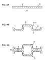
Figs. 4A to 4C are cross-sectional views showing a process of producing first and second separators according to an embodiment of the present invention; -
Fig. 5 is a perspective view showing first and second separators according to an embodiment of the present invention; -
Fig. 6 is a graph showing the relationship between a welded area ratio and the penetration resistance of first and second separators according to an embodiment of the present invention; -
Fig. 7 is a graph showing the relationship between the surface pressure and the penetration resistance of first and second separators according to an embodiment of the present invention; -
Fig. 8 is a diagram showing the structure of the penetration resistance of first and second separators according to an embodiment of the present invention; -
Fig. 9 is a schematic view of a device for measuring the penetration resistance of first and second separators according to an embodiment of the present invention; -
Fig. 10 is a graph showing the relationship between the surface pressure and the penetration resistance of first and second separators according to an embodiment of the present invention in the case where an oxide film is present or removed; -
Fig. 11 is a graph including a polarization curve of a base material in an aqueous solution; -
Fig. 12 is a graph showing the relationship between the surface roughness of the back surface and the penetration resistance of first and second separators according to an embodiment of the present invention; -
Fig. 13 is a graph showing the relationship between the surface pressure and the penetration resistance of first and second separators according to an embodiment of the present invention in the case where the surface roughness of the back surface is varied; -
Fig. 14 is a schematic view of first and second separators according to an embodiment of the present invention; -
Fig. 15 is a graph showing the relationship between the surface pressure and the penetration resistance of first and second separators according to an embodiment of the present invention in the case where the amount of compression during welding is varied; -
Fig. 16 is a schematic view showing a method of performing a corrosion-resistant treatment using a laser beam, according to an embodiment of the present invention; -
Fig. 17 is a schematic view showing a method of performing a corrosion-resistant treatment by immersing in a solution, according to an embodiment of the present invention; -
Fig. 18 is a schematic view showing a method of performing a corrosion-resistant treatment by electrolysis, according to an embodiment of the present invention; -
Fig. 19 is a graph showing a change in current during a constant potential electrolysis; -
Fig. 20 is a schematic view showing a method of corrosion resistance evaluation test using cut samples of welded portions; and -
Fig. 21 is a graph showing changes in the mass of the cut samples of welded portions in the corrosion resistance evaluation test. - An embodiment of a fuel cell separator, a fuel cell stack, and a method of producing the fuel cell stack of the present invention will now be described with reference to the attached drawings.
-
Fig. 1 is a cross-sectional view of the relevant part of a fuel cell stack in which cells having separators according to an embodiment of the present invention are stacked. In afuel cell stack 1, a plurality ofcells 2 of a fuel cell are stacked in series and an end plate (not shown) is provided at each end in the stacking direction. A plurality of tie rods (not shown) draw the end plates, thereby applying a clamping load to eachcell 2 in the stacking direction. - In a fuel cell installed in an automobile, for example, 300 to 400
cells 2 are stacked in series in thefuel cell stack 1. - The
cell 2, which is provided as a unit, includes an electrolyte membrane electrode assembly (hereinafter referred to as "membrane electrode assembly" (MEA)) 3, afirst separator 7A and asecond separator 7C. Themembrane electrode assembly 3 includes a pair of electrode catalyst layers 5A and 5C and anelectrolyte membrane 4 provided between the electrode catalyst layers 5A and 5C. Thefirst separator 7A and thesecond separator 7C formgas flow paths membrane electrode assembly 3. - The
membrane electrode assembly 3 includes the solidpolymer electrolyte membrane 4 having proton conductivity. The electrode catalyst layers 5A and 5C of either electrode are provided at either surface of a reaction area of theelectrolyte membrane 4. Furthermore,gas diffusion layers gas diffusion layers - In the fuel cell, a fuel gas is supplied to an anode, which is one of the pair of electrodes provided so as to sandwich the
electrolyte membrane 4, and an oxidizer gas is supplied to a cathode, which is the other of the pair of electrodes. Accordingly, reactions represented by formulae (1) and (2) are conducted on either surface of theelectrolyte membrane 4 to generate electric power.
Anodic reaction: H2 → 2H++ 2e- (1)
Cathodic reaction: 2H+ + 2e- + (1/2)O2 → H2O (2)
- A gasket (not shown) is disposed on a peripheral area surrounding the reaction area of the
electrolyte membrane 4 at each side of themembrane electrode assembly 3. Thefirst separator 7A and thesecond separator 7C sandwich themembrane electrode assembly 3, with the gaskets therebetween. - The
gas flow path 8A for introducing an anode gas is provided between thefirst separator 7A and thegas diffusion layer 6A. For example, hydrogen gas is supplied as the anode gas from an inlet manifold (not shown) to thegas flow path 8A and then supplied to thegas diffusion layer 6A through thegas flow path 8A. Gas not used for the reaction is discharged to an outlet manifold. - The
gas flow path 8C for introducing a cathode gas is provided between thesecond separator 7C and thegas diffusion layer 6C. For example, air is supplied as the cathode gas from an inlet manifold to thegas flow path 8C and then supplied to thegas diffusion layer 6C through thegas flow path 8C. Gas not used for the reaction is discharged to an outlet manifold. - A temperature-control
medium flow path 9 through which a temperature-control medium flows is provided between thefirst separator 7A and thesecond separator 7C. For example, cooling water is introduced as the temperature-control medium from an inlet manifold into the temperature-control medium, flowpath 9, supplied between thefirst separator 7A and thesecond separator 7C, and then discharged to an outlet manifold. The temperature-control medium absorbs heat of reaction via thefirst separator 7A and thesecond separator 7C to cool thefuel cell stack 1. - The temperature-control medium preferably has a high electric resistance. Antifreeze, which does not freeze even in cold regions, is used for fuel cells installed in automobiles.
- Each of the
first separator 7A and thesecond separator 7C is made of a metal plate. For example, SUS316L stainless steel is used for thefirst separator 7A and thesecond separator 7C in consideration of operating conditions of the fuel cell and the environment in the cell. The base material of thefirst separator 7A and thesecond separator 7C is not limited thereto and may be a stainless steel containing at least one of Fe, Ni, and Cr as a main component, a metal selected from any one of Al, Ti, Cu, Zn, Mg, Mn, Pb, Au, Ag, Pt, Pd, Ru, W, Ni, Cr, Sn, and Fe, or an alloy containing these metals as main components. - The
first separator 7A and thesecond separator 7C are produced by press forming a metal plate using a die in which the shapes of the flow path and the like are formed. The thickness of the metal plate may be set to, for example, in the range of about 0.1 to 1.0 mm. -
Fig. 2 is a cross-sectional view of thefirst separator 7A or thesecond separator 7C. Each of thefirst separator 7A and thesecond separator 7C is a corrugated plate in which projectingportions 22 adjacent to thegas diffusion layer portions 21 adjacent to anotherfirst separator 7A or anothersecond separator 7C of anadjacent cell 2 of the fuel cell are alternately arrayed. The width of eachgas flow path portion 22 and the width of the temperature-controlmedium flow path 9 formed between the projectingportions 21 may be, for example, in the range of about 0.1 to 5.0 mm. - Each of the
first separator 7A and thesecond separator 7C has a reaction-side surface 25 facing themembrane electrode assembly 3 and aback surface 26 opposite to the reaction-side surface 25. The reaction-side surface 25 forms thegas flow path back surface 26 forms the temperature-controlmedium flow path 9. - Although stainless steels exhibit corrosion resistance superior to that of other iron-based materials by the formation of a passive film, they have insufficient corrosion resistance in a strongly acidic environment, in particular, corrosion resistance in an acidic environment of sulfuric acid, which is unique to fuel cells. Accordingly, when the
first separator 7A and thesecond separator 7C are formed of a stainless steel without further treatment, corrosion may occur. - To solve this problem, in the
first separator 7A and thesecond separator 7C, which are composed of a stainless steel base material, a corrosion-resistant coating layer 27 is provided only on the reaction-side surface 25. This corrosion-resistant coating layer is not provided on theback surface 26. - The corrosion-
resistant coating layer 27 provided on the reaction-side surface 25 is made of, for example, gold (Au) and formed by plating so as to have a thickness of about 5 µm. Thus, corrosion resistance in a strongly acidic environment, in particular, corrosion resistance in an acidic environment of sulfuric acid, which is unique to fuel cells, can be ensured. - The corrosion-
resistant coating layer 27 provided on the reaction-side surface 25 is not limited to a gold-plated layer. Alternatively, the corrosion-resistant coating layer 27 may be formed by, for example, a coating using platinum (Pt), palladium (Pd), or titanium (Ti) or a surface modification treatment for improving corrosion resistance. - On the other hand, this corrosion-resistant coating layer is not formed on the back surfaces 26 of the first and
second separators first separator 7A and thesecond separator 7C. However, the oxide film increases the contact resistance between thefirst separator 7A and thesecond separator 7C and the internal resistance of the fuel cell. - To solve this problem, as shown in
Fig. 3 , weldedportions 10 are provided as joined portions for joining theback surface 26 of thefirst separator 7A and theback surface 26 of thesecond separator 7C ofadjacent cells 2 of the fuel cell. The weldedportions 10 are provided in the reaction area between the electrode catalyst layers 5A and 5C and reduce the penetration resistance of thefirst separator 7A and thesecond separator 7C. - As shown in
Fig. 3 , dimensions, such as a base end width w1, a leading end width w2, and a depth h, of each weldedportion 10 can be freely determined. When the welding depth h is set to a large value, the contact resistance between thefirst separator 7A and thesecond separator 7C can be reduced. - Examples of a method of joining the
first separator 7A and thesecond separator 7C include various welding methods, such as an electric arc welding, a laser welding, a tungsten inert gas (TIG) welding, a metal active gas (MAG) welding, a metal inert gas (MIG) welding, a plasma welding, and an electron beam welding. - The welded
portions 10 are formed by heating thesecond separator 7C disposed at the cathode side, and welding thefirst separator 7A and thesecond separator 7C. - When the welded
portions 10 are formed by heating thesecond separator 7C disposed at the cathode side to weld thefirst separator 7A and thesecond separator 7C, the leading end width w2 of the weldedportion 10 disposed on thefirst separator 7A at the anode side is smaller than the base end width w1 of the weldedportion 10 disposed on thesecond separator 7C at the cathode side. - The projecting
portions flat portions rib corner portions flat portions first separator 7A and thesecond separator 7C, the ribflat portions 21 a, which constitute groove bottoms forming thegas flow paths portions 10 joining ribflat portions 21a are formed in an area extending from eachrib corner portion 21b to the adjacentrib corner portion 22b. - A process of producing the
first separator 7A and thesecond separator 7C will now be described with reference toFigs. 4A to 4C . First, as shown inFig. 4A , a corrosion-resistant coating layer 27 is formed on abase material 31 to prepare ametal plate 32. As shown inFig. 4B , themetal plate 32 is subjected to press forming to prepare afirst separator 7A and asecond separator 7C. Subsequently, as shown inFig. 4C , back surface 26 of thefirst separator 7A and back surface 26 of thesecond separator 7C are joined by weldedportions 10. Thus, an assembly is formed by integrating thefirst separator 7A and thesecond separator 7C. - The process of producing the
first separator 7A and thesecond separator 7C is not limited thereto. Alternatively, thebase material 31 may be subjected to press forming in advance, and the corrosion-resistant coating layer 27 may then be formed on thebase material 31. - A description will be made of the operation and advantages of the
first separator 7A and thesecond separator 7C having the above structure. - In the
first separator 7A and thesecond separator 7C, the reaction-side surfaces 25 facing themembrane electrode assembly 3 require corrosion resistance at a high temperature, a high humidity, and in an acidic atmosphere. In order to meet this need, by forming the corrosion-resistant coating layer 27 which is not readily degraded by oxidation on each reaction-side surface 25, the stainless steel, which is the base material of thefirst separator 7A and thesecond separator 7C, can be protected. Accordingly, satisfactory corrosion resistance can be provided. Furthermore, conductivity of each reaction-side surface 25 can be maintained via the corrosion-resistant coating layer 27. Consequently, low contact resistances between thefirst separator 7A and themembrane electrode assembly 3 and between thesecond separator 7C and themembrane electrode assembly 3 can be maintained. - On the other hand, in the
first separator 7A and thesecond separator 7C, corrosion resistance required for the back surfaces 26 constituting the temperature-controlmedium flow path 9 is lower than that for the reaction-side surfaces 25. Accordingly, the corrosion-resistant coating layer is not formed on eachback surface 26. Consequently, the work-hours for forming the corrosion-resistant coating layer 27 can be reduced and the amount of noble metal used for the corrosion-resistant coating layer 27 can also be reduced compared with a known structure in which the corrosion-resistant coating layer is formed on bothsurfaces first separator 7A and thesecond separator 7C. Accordingly, the cost of the fuel cell can be reduced. - Although the corrosion-resistant coating layer is not formed on each
back surface 26, theback surface 26 is exposed to cooling water (temperature-control medium) flowing through the temperature-controlmedium flow path 9 during the operation of the fuel cell. As a result, a passivation treatment is performed on eachback surface 26 to form an oxide film thereon, thus improving corrosion resistance of theback surface 26. - The oxide film formed on the surface of the
back surface 26 is an insulating film. However, since theback surface 26 of thefirst separator 7A and theback surface 26 of thesecond separator 7C ofadjacent cells 2 of the fuel cell are joined by the weldedportions 10, the penetration resistance of thefirst separator 7A and thesecond separator 7C can be reduced at the weldedportions 10. Accordingly, the power generation performance of the fuel cell can be improved. - Furthermore, since the
first separator 7A and thesecond separator 7C are integrated by the weldedportions 10, misalignment of both separators can be prevented and the number of components constituting thefuel cell stack 1 can be reduced, thus facilitating easy assembly of thefuel cell stack 1. - By forming the welded
portions 10, the corrosion-resistant coating layer 27 is removed and the base material may be exposed to the surface. To solve this problem, welding of the weldedportions 10 is performed from the cathode side so that damage of the corrosion-resistant coating layer 27 due to the formation of the weldedportions 10 can be suppressed on thefirst separator 7A disposed at the anode side, which is more susceptible to corrosion than thesecond separator 7C disposed at the cathode side. Accordingly, a decrease in corrosion-resistant performance can be minimized. - In Example 1, as shown in
Fig. 5 , linear weldedportions 11 and dot weldedportions 12 are provided on afirst separator 7A and asecond separator 7C in any arrangement in accordance with the dimensions of projectingportions separators - When
flow paths first separator 7A and thesecond separator 7C linearly extend, projectingportions 21 are in contact with each other without any clearance. On the other hand, when theflow paths portions 21. Accordingly, the linear weldedportions 11 and dot weldedportions 12 are appropriately arranged in combinations in accordance with a distribution state of contact portions of thefirst separator 7A and thesecond separator 7C. - When the ratio of a welded area (joined area) corresponding to the welded
portion 10 to the contact area of thefirst separator 7A and thesecond separator 7C is defined as a welded area ratio (joined area ratio), the welded area ratio is set to 5% or more. - The welded
portion 10 may be formed by joining the entire areas of ribflat portions 21a (seeFig. 3 ). In this case, crevice corrosion caused between adjacent ribflat portions 21a can be suppressed. -
Fig. 6 shows experimental results of measured penetration resistances of thefirst separator 7A and thesecond separator 7C in the case where the welded area ratio was varied while thefirst separator 7A and thesecond separator 7C were compressed with a predetermined load. Referring toFig. 6 , when welding was not performed, that is, when the welded area ratio was 0%, the contact resistance between thefirst separator 7A and thesecond separator 7C was high. The penetration resistance was markedly decreased until the welded area ratio was increased to 5%. The penetration resistance was then gradually decreased as the welded area ratio exceeded 5% and was increased to 100%. That is, the point at which the welded area ratio was 5% is a turning point of this characteristic. Accordingly, when the welded area ratio is set to 5%, the penetration resistance of thefirst separator 7A and thesecond separator 7C can be sufficiently decreased, and in addition, the work-hours for welding can be reduced, thereby increasing productivity. -
Fig. 7 shows experimental results of measured penetration resistances of thefirst separator 7A and thesecond separator 7C in the case where the surface pressure between thefirst separator 7A and thesecond separator 7C was varied. InFig. 7 , characteristic "a" represents a result in the case where thefirst separator 7A and thesecond separator 7C were welded with a welded area ratio of 50%, and characteristic "b" represents a result in the case where thefirst separator 7A and thesecond separator 7C were not welded. Referring toFig. 7 , in the sample in which thefirst separator 7A and thesecond separator 7C were welded, the resistance could be markedly decreased and the change in the resistance relative to the change in the surface pressure was small, compared with the sample in which thefirst separator 7A and thesecond separator 7C were not welded. -
Fig. 8 shows the configuration of an electric conduction path of thefirst separator 7A and thesecond separator 7C. When the welded area ratio is not 100%, the penetration resistance R in the electric conduction path is represented by a parallel combined resistance of a resistance Ra of the weldedportion 10, a penetration resistance Rb of the base material, and a contact resistance Rc at the contact portion between the back surfaces 26 and satisfies the following relationship:
-
Fig. 9 shows a measuringdevice 14 for measuring the penetration resistance of thefirst separator 7A and thesecond separator 7C. In this measuringdevice 14, thefirst separator 7A and thesecond separator 7C are sandwiched between terminal blocks 15 made of thick plates, and a current I (A) is supplied between the terminal blocks 15 while a compressive load is applied to the terminal blocks 15. In this case, the voltage V (V) between the terminal blocks 15 is determined. The resistance R (Ω) is calculated from the current I (A) and the voltage V (V) using Ohm's law. - In Example 2, oxide films on the
back surface 26 of thefirst separator 7A and theback surface 26 of thesecond separator 7C are removed and the back surfaces 26 thereof are then welded. - In this example, to remove the oxide film, base materials of the
first separator 7A and thesecond separator 7C are immersed in a sulfuric acid-acidic solution, and a predetermined electrical potential is applied to the base materials. -
Fig. 10 shows experimental results of measured penetration resistances of thefirst separator 7A and thesecond separator 7C in the case where the surface pressure between thefirst separator 7A and thesecond separator 7C was varied. InFig. 10 , characteristic A represents a result in the case where the welding was performed without removing the oxide films on the back surfaces 26, characteristic B represents a result in the case where the oxide films on the back surfaces 26 were removed with an acid and the welding was then performed, and characteristic C represents a result in the case where the oxide films on the back surfaces 26 were removed by an acid and electrolysis and the welding was then performed. These results showed that the penetration resistance in characteristics B and C was markedly lower than that of characteristic A, and the penetration resistance in characteristic C was lower than that in characteristic B in a low surface pressure range. -
Fig. 11 shows a polarization curve of a base material in an aqueous solution. In the step of removing the oxide film, regardless of the presence or absence of the oxide film, the electrical potential applied to the base material is set to be lower than the corrosion potential Ecorr of the base material in the solution. In this example, SUS316L is used for the base material, and the corrosion potential Ecorr of the base material is 0.25 V vs. standard hydrogen electrode (SHE) in the state where the oxide film is formed. Accordingly, an electrical potential of -0.5 V vs. SHE is maintained for one minute in a solution with a pH of 4 to remove the oxide film. - Considering that a large number of separators are treated to remove oxide films, the acidity of the solution is preferably pH = 2 to 7, and the temperature is preferably from room temperature to the operating temperature of the fuel cell, i.e., about 60°C to 100°C. The electrolysis time is preferably short, though it depends on the area of the plate.
- The corrosion-
resistant coating layer 27 provided on the reaction-side surface 25 has corrosion resistance in the operating environment of the fuel cell. Therefore, except for specific aqueous solution environments (for example, strongly acidic conditions (pH < 1), high temperatures (> 200°C), and high halogen concentrations (fluorine (F) ion concentration > 1%), even when the entire separators are immersed in an aqueous solution to remove oxide films, the corrosion-resistant coating layer 27 on the reaction-side surface 25 is not damaged. - In Example 3, oxide films on the
back surface 26 of thefirst separator 7A and theback surface 26 of thesecond separator 7C are removed by machining, i.e., grinding and the back surfaces 26 thereof are then welded. - The surface roughness of the
back surface 26 of thefirst separator 7A and theback surface 26 of thesecond separator 7C is controlled to a predetermined surface roughness X-2 (seeFig. 12 ) at portions surrounded by the temperature-controlmedium flow path 9 so as to increase conductive properties. On the other hand, at portions facing gaskets (not shown), the surface roughness is controlled to a value smaller than the surface roughness X-2 so as to improve the sealing property. -
Fig. 12 shows experimental results of measured penetration resistances of thefirst separator 7A and thesecond separator 7C, which were made of a metal X or a metal Y, in the case where the surface roughness of theback surface 26 of thefirst separator 7A and theback surface 26 of thesecond separator 7C was varied. Referring toFig. 12 , there is an absolute difference in the penetration resistance due to the difference in the material of the metal X and the metal Y. However, in each of the metal X and the metal Y, a sensitivity of resistance is present with respect to the surface roughness. The resistance of the metal X becomes the minimum at a surface roughness of X-2. -
Fig. 13 shows experimental results of measured penetration resistances of thefirst separator 7A and thesecond separator 7C having a surface roughness of X-1 or X-2 in the case where the surface pressure between thefirst separator 7A and thesecond separator 7C was varied. Referring toFig. 13 , regardless of the value of the surface pressure, the first andsecond separators - In Example 4, the
back surface 26 of thefirst separator 7A and theback surface 26 of thesecond separator 7C are welded while theseparators -
Fig. 14 is a schematic view of thefirst separator 7A and thesecond separator 7C viewed from a reaction-side surface 25. In thefirst separator 7A and thesecond separator 7C, linear weldedportions 11 are provided on areas linearly extending from aninlet manifold 41 and anoutlet manifold 42 of agas flow path 8A, and dot weldedportions 12 are provided between the linear weldedportions 11 at predetermined intervals. - The linear welded
portions 11 and the dot weldedportions 12 are arranged so that the penetration resistance of thefirst separator 7A and thesecond separator 7C at any position in a reaction area which is the farthest from these welded portions is a predetermined value (for example, 200 mΩ·cm2) or less. - As described above, when the linear welded
portions 11 and the dot weldedportions 12 are appropriately arranged in accordance with the shape of thegas flow path 8A, the penetration resistance of thefirst separator 7A and thesecond separator 7C can be effectively reduced. -
Fig. 15 shows experimental results of measured penetration resistances of thefirst separator 7A and thesecond separator 7C in the case where the surface pressure between thefirst separator 7A and thesecond separator 7C was varied. InFig. 15 , characteristic P represents a result in the case where thefirst separator 7A and thesecond separator 7C were not welded, characteristic Q represents a result in the case where thefirst separator 7A and thesecond separator 7C were welded while a surface pressure smaller than the predetermined value was applied to theback surface 26 of thefirst separator 7A and theback surface 26 of thesecond separator 7C, and characteristic R represents a result in the case where thefirst separator 7A and thesecond separator 7C were welded while the predetermined surface pressure was applied to theback surface 26 of thefirst separator 7A and theback surface 26 of thesecond separator 7C. These results showed that the penetration resistances of characteristics Q and R were markedly lower than the penetration resistance of characteristic P, and the penetration resistance of characteristic R was lower than that of characteristic Q over the entire range. - In Example 5, the
first separator 7A and thesecond separator 7C are welded, and a corrosion-resistant treatment is then performed by heat-treating at least the weldedportions 10. In the heat treatment, thefirst separator 7A and thesecond separator 7C after the welding are placed in a furnace and heated by increasing the temperature. - Corrosion resistance of the welded
portions 10 is decreased because of a change in the structure and a residual stress due to the thermal effect during welding. Consequently, on the reaction-side surface 25 of thesecond separator 7C disposed at the cathode side, the corrosion-resistant coating layer 27 is damaged at the weldedportions 10 and peripheries thereof. However, the heat treatment is performed on the weldedportions 10 and peripheries thereof, thereby suppressing the decrease in corrosion resistance due to the change in the structure and the residual stress during welding. - The method of performing the heat treatment is not limited thereto, and another heating method may be employed.
- In Example 6, the
first separator 7A and thesecond separator 7C are welded, and a corrosion-resistant treatment is then performed by irradiating alaser beam 19 at least on the surfaces of the weldedportions 10. -
Fig. 16 shows a process of welding thefirst separator 7A and thesecond separator 7C. The reaction-side surface 25 of thesecond separator 7C disposed at the cathode side is irradiated with thelaser beam 19 in a room-temperature atmosphere to form the weldedportion 10. After the welding, as a corrosion-resistant treatment, the surface of the weldedportion 10 and the periphery of the weldedportion 10 are irradiated with thelaser beam 19 to heat the irradiated areas in the range of 80°C to 200°C. Thus, anoxide film 28 is formed on the irradiated areas. - In the corrosion resistance treatment, after the welding, the
laser beam 19 is irradiated while the output thereof is continuously decreased, thereby forming theoxide film 28 on the irradiated areas. - Alternatively, in the corrosion resistance treatment, after the welding, the
laser beam 19 may be irradiated while the focusing area thereof is continuously expanded, thereby forming theoxide film 28 on the irradiated areas. - Corrosion resistance of the welded
portions 10 is decreased because of a change in the structure and a residual stress due to the thermal effect during welding. Consequently, on the reaction-side surface 25 of thesecond separator 7C disposed at the cathode side, the corrosion-resistant coating layer 27 is damaged at the weldedportions 10 and peripheries thereof. However, the corrosion-resistant treatment is performed by forming theoxide film 28 on the surfaces of the weldedportions 10 and peripheries thereof, thereby suppressing the occurrence of corrosion on these portions. Furthermore, a heat treatment is locally performed by irradiating thelaser beam 19. Accordingly, damage of the corrosion-resistant coating layer 27 can be suppressed. - When the
laser beam 19 is irradiated while the output thereof is changed, welding and the heat treatment for forming theoxide film 28 can be continuously performed, thus markedly reducing the work-hours of this process. Furthermore, since the irradiated areas are limited to the weldedportions 10 and peripheries thereof using thelaser beam 19, the thermal effect on thefirst separator 7A and thesecond separator 7C can be reduced. - When the
laser beam 19 is irradiated while the focusing area thereof is changed, welding and the heat treatment for forming theoxide film 28 can be continuously performed, thus markedly reducing the work-hours of this process. Furthermore, since the irradiated areas are limited to the weldedportions 10 and peripheries thereof using thelaser beam 19, the thermal effect on thefirst separator 7A and thesecond separator 7C can be reduced. - When the low-temperature heat treatment at about 80°C to 200°C is performed by the irradiation of the
laser beam 19 to form theoxide film 28, a passive film that can withstand the operating environment of the fuel cell is formed. In contrast, when theoxide film 28 is formed by heating at 80°C or lower, a satisfactory passive film that can withstand the operating environment of the fuel cell cannot be formed. When theoxide film 28 is formed by heating at 200°C or higher, theoxide film 28 may be grown and a scale of theoxide film 28 may be formed. In such a case, the contact resistance between thefirst separator 7A and thesecond separator 7C may be increased. - On the reaction-
side surface 25 of thefirst separator 7A disposed at the anode side, when the corrosion-resistant coating layer 27 is damaged at the weldedportions 10 and peripheries thereof, a corrosion-resistant treatment can be performed by irradiating thelaser beam 19 with a reduced output on the surfaces of the weldedportions 10 and peripheries thereof to form theoxide film 28. Accordingly, the occurrence of corrosion on these portions can be suppressed. - Other heating methods may be employed for forming the
oxide film 28. - In Example 7, the
first separator 7A and thesecond separator 7C are welded, and a corrosion-resistant treatment is then performed by immersing at least the weldedportions 10 in an aerated acidic solution with a pH of 4 or less to form an oxide film. - As shown in
Fig. 17 , welded first andsecond separators acidic solution 61 at 50°C for two hours to form a passive film on the weldedportions 10. More specifically, grooves having the weldedportions 10 are filled with the nitric acid-acidic solution 61. - Considering the corrosion-resistant treatment of a large number of welded first and
second separators second separators - The acidity of the 4.8 M nitric acid-
acidic solution 61 is significantly higher than the pH in the fuel cell environment, and nitrate ions have high oxidizing properties. Therefore, a stable passive film that can withstand the operating environment of the fuel cell is formed on the surface of the SUS316L base material, which has been exposed by welding. The use of this method is advantageous in that a corrosion-resistant treatment of welded portions can be performed by simply immersing the welded portions in a solution. Furthermore, since the corrosion-resistant coating layer 27 is provided on the reaction-side surfaces 25 of thefirst separator 7A and thesecond separator 7C, the reaction-side surfaces 25 are not affected by the acid. - By immersing the welded
portions 10 in a solution with a pH in the fuel cell environment or lower, a passive film can be selectively formed on the weldedportions 10, thus suppressing the occurrence of corrosion on the weldedportions 10. On the other hand, when the weldedportions 10 are immersed in a solution having a pH higher than the value described above, a passive film that can withstand the fuel cell environment cannot be formed. - In Example 8, the
first separator 7A and thesecond separator 7C are welded, and a corrosion-resistant treatment is then performed by forming an oxide film by constant potential electrolysis while at least the weldedportions 10 are immersed in an aerated acidic solution with a pH of 4 or less. - As shown in
Fig. 18 , welded first andsecond separators current control device 74 includes anelectrode 75 connected to the first andsecond separators electrode 72 connected to the solution 71, and areference electrode 73 for monitoring electric potential. The potential/current control device 74 provides the surface of thesecond separator 7C immersed in the solution 71 with a predetermined current and a predetermined potential via thereference electrode 73. - The potential applied to the surface of the
second separator 7C is set in the range of 0.3 to 0.6 V (vs. SHE) on the basis of the graph of the polarization curve shown inFig. 11 . Accordingly, a passive film is formed on the surfaces of the weldedportions 10. In contrast, when the potential is set to 0.3 V or less or 0.6 V or more, a passive film cannot be satisfactorily formed on the surfaces of the weldedportions 10. -
Fig. 11 is a polarization curve obtained by immersing a test piece of a SUS316L base material in an aerated sulfuric acid-acidic solution with a pH of 4 at room temperature, and then performing a potentiodynamic polarization measurement. According to this result, the SUS316L material is passivated in a potential range of 0.3 to 0.6 V vs. SHE. - Accordingly, in this example, a stable passive film is formed on the welded portions by performing constant potential polarization at a potential of 0.5 V vs. SHE for 30 minutes.
-
Fig. 19 is a graph showing a change in current in the SUS316L base material measured during constant potential electrolysis. Referring toFig. 19 , the current converges to a certain value after a 30-minute polarization. This result shows that a stable passive film is formed on the weldedportions 10. - In this example, it is believed that the
second separator 7C disposed at the cathode side is maintained in a potential range of 0.4 to 1.0 V vs. SHE during the operation of the fuel cell. Accordingly, a stable passive film is formed by polarizing at a potential of 0.5 V vs. SHE. In this example, an oxide film is forcibly formed on the surfaces of the weldedportions 10 by applying a potential. Accordingly, a stable passive film can be formed compared with a method of simply immersing the weldedportions 10 in an acidic solution. - In the method using constant potential electrolysis, an aerated solution with a pH in the range of about 1 to 7 is used, and the electrolysis time is about 1 to 30 minutes. In such a case, a stable passive film can be formed.
- Corrosion resistance of the first and
second separators portion 10 by the method described in Example 5, Example 7, or Example 8 was confirmed as follows. The corrosion-resistant treatment was performed in accordance with the method described in Example 5, 7, or 8, and a welded portion was then randomly cut out from the first andsecond separators Fig. 20 , thecut samples 101 of the welded portion were immersed in a sulfuric acid-acidic solution 100 at 80°C with a pH of 4, the acidic solution being prepared in a container, and a change in the mass before and after the immersion was measured with time. Thus, corrosion resistance of the sample prepared by performing each corrosion-resistant treatment was evaluated. In this evaluation test, a corrosion-resistant treatment was performed on the cut surfaces of the samples using a silicone sealing material. -
Fig. 21 is a graph showing a change in the mass of thecut samples 101 of the welded portion by corrosion in the case where thecut samples 101 were immersed in the solution for 200 hours. InFig. 21 , characteristic A represents a result in the case where no corrosion-resistant treatment was performed, characteristic B represents a result in the case where a low-temperature heat treatment was performed at 100°C for one minute, characteristic C represents a result in the case where a sample was immersed in a 4.8 M nitric acid solution at 50°C for two hours, and characteristic D represents a result in the case where electrolysis was performed at a potential of 0.5 V vs. SHE for 30 minutes while the sample was immersed in a sulfuric acid solution at room temperature with a pH of 2. As shown inFig. 21 , the change in the mass by corrosion was marked in characteristic A, and decreased in the order of characteristic B, characteristic C, and characteristic D. - Compared with these corrosion-resistant treatments, to simplify the pretreatment, the method of performing a low-temperature heat treatment described in Example 5 is preferred. To form a stable passive film and to simplify the process, the method of simply immersing in a solution described in Example 7 is preferred. To reliably form a passive film, the method of immersing and performing electrolysis described in Example 8 is preferred.
- The above-described embodiments afford advantages described below.
- (A) A
cell 2 of a fuel cell includes amembrane electrode assembly 3 and metal first andsecond separators membrane electrode assembly 3 includes a pair of electrode catalyst layers 5A and 5C and anelectrolyte membrane 4 provided between the electrode catalyst layers 5A and 5C. Thefirst separator 7A and thesecond separator 7C are disposed at either side of themembrane electrode assembly 3 to formgas flow paths back surface 26 of thefirst separator 7A and aback surface 26 of thesecond separator 7C, thefirst separator 7A and thesecond separator 7C being included inadjacent cells 2 of the fuel cell, are in contact with each other, thereby forming a temperature-controlmedium flow path 9 through which a temperature control medium is supplied, the temperature controlmedium flow path 9 being disposed between thefirst separator 7A and thesecond separator 7C. In thefirst separator 7A and thesecond separator 7C, corrosion-resistant coating layers 27 are provided only on reaction-side surfaces 25 of thefirst separator 7A and thesecond separator 7C, the reaction-side surfaces 25 facing themembrane electrode assembly 3, and portions where theback surface 26 of thefirst separator 7A is in contact with theback surface 26 of thesecond separator 7C are joined. Accordingly, corrosion resistance of thefirst separator 7A and thesecond separator 7C can be ensured by the presence of the corrosion-resistant coating layer 27. Furthermore, the work-hours for forming the corrosion-resistant coating layer 27 on theback surface 26 of thefirst separator 7A and theback surface 26 of thesecond separators 7C can be reduced, thereby reducing the cost of the fuel cell. The resistance between the back surfaces 26, on which the corrosion-resistant coating layer 27 is not formed, can be reduced via a portion (welded portion 10) joining the back surfaces 26. Accordingly, the power generation performance of the fuel cell can be improved. - (B) A base material of the first and
second separators back surface 26 of thefirst separator 7A and theback surface 26 of thesecond separator 7C, thereby ensuring corrosion resistance required for the back surfaces 26 constituting the temperature-controlmedium flow path 9. - (C) Portions (rib
flat portions 21a) constituting groove bottoms of thegas flow paths first separator 7A and thesecond separator 7C, respectively, are welded. Accordingly, the weldedportions 10 are formed at positions distant from themembrane electrode assembly 3, and thus the weldedportions 10 are not relatively readily corroded. Therefore, even when the corrosion-resistant coating layer 27 is damaged by the formation of the weldedportions 10, a decrease in corrosion-resistant performance can be suppressed. - (D) Each of the
first separator 7A and thesecond separator 7C includes ribflat portions rib corner portions flat portions portions 10 joining the ribflat portions 21a are formed in an area extending from eachrib corner portion 21b to the adjacentrib corner portion 22b. Accordingly, the weldedportion 10 joins the entire area of each ribflat portion 21a, thereby increasing the welded area and reducing the resistance between the back surfaces 26. Furthermore, crevice corrosion caused between adj acent ribflat portions 21 a can be suppressed. - (E) The ratio of a welded area to the contact area of the
first separator 7A and thesecond separator 7C is set to 5% or more. Accordingly, the resistance between thefirst separator 7A and thesecond separator 7C can be reduced, thereby improving the power generation performance of the fuel cell. - (F) Oxide films on the
back surface 26 of thefirst separator 7A and theback surface 26 of thesecond separator 7C are removed, and theback surface 26 of thefirst separator 7A and theback surface 26 thesecond separator 7C are then welded. Accordingly, the contact resistance between thefirst separator 7A and thesecond separator 7C can be reduced, thereby improving the power generation performance of the fuel cell. - (G) Oxide films on the
back surface 26 of thefirst separator 7A and theback surface 26 of thesecond separator 7C are removed by applying a predetermined potential to thefirst separator 7A and thesecond separator 7C in a solution, and theback surface 26 of thefirst separator 7A and theback surface 26 thesecond separator 7C are then welded. Accordingly, the contact resistance between thefirst separator 7A and thesecond separator 7C can be reduced, thereby improving the power generation performance of the fuel cell. - (H) Oxide films on the
back surface 26 of thefirst separator 7A and theback surface 26 of thesecond separator 7C are removed by grinding, and theback surface 26 of thefirst separator 7A and theback surface 26 thesecond separator 7C are then welded. Accordingly, the contact resistance between thefirst separator 7A and thesecond separator 7C can be reduced, thereby improving the power generation performance of the fuel cell. - (I) The
back surface 26 of thefirst separator 7A and theback surface 26 thesecond separator 7C are welded while thefirst separator 7A and thesecond separator 7C are compressed with a predetermined load. Accordingly, the resistance between thefirst separator 7A and thesecond separator 7C can be reduced, thereby improving the power generation performance of the fuel cell. - (J) The welded
portions 10 are formed by heating thesecond separator 7C disposed at the cathode side, and welding thefirst separator 7A and thesecond separator 7C. Accordingly, damage of the corrosion-resistant coating layer 27 due to the formation of the weldedportions 10 can be suppressed on thefirst separator 7A disposed at the anode side, which is more susceptible to corrosion than thesecond separator 7C disposed at the cathode side. Thus, a decrease in corrosion-resistant performance can be minimized. - (K) The
first separator 7A and thesecond separator 7C are welded, and a corrosion-resistant treatment is then performed at least on the surfaces of the weldedportions 10. Accordingly, even when the corrosion-resistant coating layer 27 is damaged by forming the weldedportions 10, the occurrence of corrosion on these portions can be suppressed. - (L) As the corrosion-resistant treatment, a heat treatment is performed at least on the welded
portions 10. Accordingly, an effect of decreasing corrosion resistance caused by a change in the structure during welding and a residual stress can be reduced. - (M) As the corrosion-resistant treatment, an oxide film is formed at least on the surfaces of the welded
portions 10. Accordingly, at least the surfaces of the weldedportions 10 are passivated by the oxide film, thereby suppressing the occurrence of corrosion at these surfaces. - (N) As the corrosion-resistant treatment, an oxide film is formed by irradiating a
laser beam 19 on at least the surfaces of the weldedportions 10. Accordingly, the weldedportions 10 and peripheries thereof are locally heated, thereby reducing the thermal effect on the other areas. - (O) Welding is performed by irradiating the
laser beam 19 on thesecond separator 7C disposed at the cathode side, and an oxide film is then formed on the surface of the weldedportion 10 by irradiating thelaser beam 19 with a reduced output on the weldedportion 10. Accordingly, welding and a heat treatment for forming the corrosion-resistant film of the weldedportion 10 can be continuously performed, thus markedly reducing the work-hours of this process. - (P) Welding is performed by irradiating the
laser beam 19 on thesecond separator 7C disposed at the cathode side, and an oxide film is then formed on the surface of the weldedportion 10 by irradiating thelaser beam 19 on the weldedportion 10 while the focusing area thereof is expanded. Accordingly, welding and a heat treatment for forming the corrosion-resistant film of the weldedportion 10 can be continuously performed, thus markedly reducing the work-hours of this process. - (Q) As the corrosion-resistant treatment, an oxide film is formed by immersing at least the surfaces of the welded
portions 10 in an acidic solution. Accordingly, at least the surfaces of the weldedportions 10 are passivated by the oxide film, thereby suppressing the occurrence of corrosion at these surfaces. - (R) As the corrosion-resistant treatment, an oxide film is formed by electrolysis while at least the surfaces of the welded
portions 10 are immersed in an acidic solution. Accordingly, at least the surfaces of the weldedportions 10 are passivated by the oxide film, thereby suppressing the occurrence of corrosion at these surfaces. - While the invention has been disclosed with reference to certain preferred embodiments, numerous modifications, alterations, and changes to the described embodiments are possible. Accordingly, it is intended that the invention not be limited to the described embodiments, but that it have the full scope defined by the language of the following claims.
Claims (12)
- A fuel cell stack comprising: a membrane electrode assembly including electrode catalyst layers and an electrolyte membrane between the electrode catalyst layers; a metal separator on each side of first and second surfaces of the membrane electrode assembly, each metal separator having a corrosion-resistant coating layer provided only on a reaction-side surface facing the membrane electrode assembly, each metal separator constituting gas flow paths, the membrane electrode assembly and the metal separators constituting a cell of a fuel cell; and a temperature-control medium flow path provided by forming joined portions where back surfaces of the metal separators of adjacent stacked cells are in contact with each other, characterized in that the joined portions are formed by welding portions of the metal separators that constitute groove bottoms of the gas flow paths and wherein an oxide film is provided on a surface of respective welded portions, wherein the oxide film is formed by at least one treatment of:heat-treating the welded portions,irradiating a laser beam on the surfaces of the welded portions,immersing the surfaces of the welded portions in an acidic solution orperforming electrolysis while the surfaces of the welded portions are immersed in an acidic solution.
- The fuel cell stack according to Claim 1, wherein a base material of the separators comprises a stainless steel containing at least one of Fe, Ni, and Cr as a main component.
- The fuel cell stack according to Claim 1, wherein each of the metal separators has a corrugated shape including projecting portions constituting one of the gas flow paths provided on the membrane electrode assembly, and recesses constituting the temperature-control medium flow path, and peripheral portions of planar surfaces each disposed on the top of respective projecting portions, which constitute the groove bottom of the gas flow path, are joined by welding.
- The fuel cell stack according to any one of Claims 1 to 3, wherein a ratio of a joined area corresponding to a joined portion to the contact area where the back surfaces of the metal separators are in contact with each other is 5% or more.
- A method of producing a fuel cell stack comprising the steps of: forming a corrosion-resistant coating layer on a surface of individual metal separators;
forming a temperature control medium flow path by joining portions where surfaces of the metal separators of adjacent stacked cells not having the corrosion- resistant coating layer thereon are in contact with each other;
forming gas flow paths by joining the corrosion-resistant coating layers of the metal separators on each side of first and second surfaces of a membrane electrode assembly, the membrane electrode assembly including electrode catalyst layers and an electrolyte membrane between the electrode catalyst layers; and characterized by a step of performing a corrosion-resistant treatment on surfaces of welded portions of the joined portions after the step of forming the temperature control medium flow path; wherein the corrosion-resistant treatment is performed by at least one of:heat treating the welded portions;irradiating a laser beam on the surfaces of the welded portions to form an oxide film;immersing the surfaces of the welded portions in an acidic solution to form an oxide film;performing electrolysis while the surfaces of the welded portions are immersed in an acidic solution to form an oxide film. - The method of producing a fuel cell stack according to Claim 5, further comprising a step of: before the step of forming the temperature control medium flow path, removing an oxide film on the portions to be joined.
- The method of producing a fuel cell stack according to Claim 6, wherein the oxide film is removed by immersing the portions to be joined in a solution and applying a predetermined potential to the metal separators.
- The method of producing a fuel cell stack according to Claim 6, wherein the oxide film is removed by grinding the oxide film on the portions to be joined.
- The method of producing a fuel cell stack according to Claim 5, wherein the temperature control medium flow path is formed while the portions to be joined are compressed.
- The method of producing a fuel cell stack according to Claim 5, wherein, before the step of forming the temperature control medium flow path, the metal separator disposed at a cathode side of the membrane electrode assembly is heated.
- The method of producing a fuel cell stack according to Claim 5, wherein, in the step of forming the temperature-control medium flow path, the metal separator disposed at a cathode side is irradiated with a laser beam to form the welded portions, and the corrosion-resistant treatment is then performed by irradiating the laser beam with a reduced output on the surfaces of the welded portions.
- The method of producing a fuel cell stack according to Claim 11, wherein, in the step of forming the temperature-control medium flow path, the metal separator disposed at the cathode side is irradiated with a laser beam to form the welded portions, and the corrosion-resistant treatment is then performed by irradiating the laser beam on the surfaces of the welded portions while the focusing area of the laser beam is expanded.
Applications Claiming Priority (2)
| Application Number | Priority Date | Filing Date | Title |
|---|---|---|---|
| JP2006136709A JP5343307B2 (en) | 2006-05-16 | 2006-05-16 | FUEL CELL STACK, FUEL CELL SEPARATOR, AND METHOD FOR PRODUCING THE SAME |
| PCT/IB2007/001257 WO2007135509A1 (en) | 2006-05-16 | 2007-05-15 | Fuel cell stack and method of producing its separator plates |
Publications (2)
| Publication Number | Publication Date |
|---|---|
| EP2025027A1 EP2025027A1 (en) | 2009-02-18 |
| EP2025027B1 true EP2025027B1 (en) | 2011-03-23 |
Family
ID=38476377
Family Applications (1)
| Application Number | Title | Priority Date | Filing Date |
|---|---|---|---|
| EP07734565A Expired - Fee Related EP2025027B1 (en) | 2006-05-16 | 2007-05-15 | Fuel cell stack and method of producing its separator plates |
Country Status (6)
| Country | Link |
|---|---|
| US (1) | US8263289B2 (en) |
| EP (1) | EP2025027B1 (en) |
| JP (1) | JP5343307B2 (en) |
| CA (1) | CA2651627C (en) |
| DE (1) | DE602007013393D1 (en) |
| WO (1) | WO2007135509A1 (en) |
Families Citing this family (26)
| Publication number | Priority date | Publication date | Assignee | Title |
|---|---|---|---|---|
| DE102007024161A1 (en) | 2007-05-24 | 2008-11-27 | Daimler Ag | Bipolar plate for fuel cells |
| KR101813919B1 (en) * | 2008-06-23 | 2018-01-02 | 누베라 퓨엘 셀스, 엘엘씨 | Fuel cell with reduced mass transfer limitations |
| CN102049601B (en) * | 2010-10-30 | 2014-07-02 | 上海交通大学 | Current-assisted fuel cell ultra-thin metal bipolar plate pressure welding device and method |
| JP5336619B2 (en) * | 2011-04-07 | 2013-11-06 | 本田技研工業株式会社 | Metal separator for fuel cell and its noble metal coating method |
| FR2976128B1 (en) * | 2011-05-30 | 2014-06-06 | Commissariat Energie Atomique | FUEL CELL LIMITING THE PHENOMENON OF CORROSION |
| KR101316529B1 (en) * | 2011-07-06 | 2013-10-08 | 기아자동차주식회사 | Fuel Cell Stack Structure |
| JP6366086B2 (en) * | 2012-03-15 | 2018-08-01 | 日産自動車株式会社 | Fuel cell stack |
| FR2995146B1 (en) * | 2012-09-03 | 2015-07-03 | Commissariat Energie Atomique | FUEL CELL LIMITING THE PHENOMENON OF CORROSION |
| WO2014185193A1 (en) * | 2013-05-16 | 2014-11-20 | 日産自動車株式会社 | Apparatus and method for producing fuel cell separator assembly |
| WO2015011990A1 (en) * | 2013-07-22 | 2015-01-29 | 日産自動車株式会社 | Attachment structure for deformation absorption member and attachment method |
| JP6287721B2 (en) * | 2014-09-17 | 2018-03-07 | トヨタ車体株式会社 | Polymer electrolyte fuel cell and separator |
| US10522850B2 (en) * | 2014-09-30 | 2019-12-31 | The Government Of The United States Of America, As Represented By The Secretary Of The Navy | Three-dimensionally printed bipolar plate for a proton exchange membrane fuel cell |
| JP6493549B2 (en) * | 2015-10-06 | 2019-04-03 | 日産自動車株式会社 | Fuel cell stack |
| JP6727095B2 (en) * | 2016-10-17 | 2020-07-22 | 三菱重工業株式会社 | Dissimilar metal joining method |
| TWI624989B (en) | 2016-12-14 | 2018-05-21 | 財團法人工業技術研究院 | Bipolar plate, fuel cell and fuel cell stack |
| CN110234460B (en) * | 2017-02-24 | 2021-06-29 | Nok株式会社 | Laser welding method |
| FR3073324B1 (en) * | 2017-11-08 | 2019-10-25 | Commissariat A L'energie Atomique Et Aux Energies Alternatives | METHOD USING A LASER FOR WELDING BETWEEN TWO METALLIC MATERIALS OR FOR POWDER FRITTAGE (S), APPLICATION TO THE PRODUCTION OF BIPOLAR PLATES FOR PEMFC CELLS |
| JP7021551B2 (en) * | 2018-02-08 | 2022-02-17 | トヨタ自動車株式会社 | Fuel cell stack |
| JP7010077B2 (en) * | 2018-03-13 | 2022-02-10 | トヨタ車体株式会社 | Method for manufacturing a fuel cell separator joint and a fuel cell separator joint |
| DE102019202493A1 (en) | 2019-02-25 | 2020-08-27 | Audi Ag | Method for producing a bipolar plate strand, method for producing a bipolar plate and device for carrying out the method |
| JP7215384B2 (en) * | 2019-09-24 | 2023-01-31 | トヨタ自動車株式会社 | Fuel cell manufacturing method |
| JP7322813B2 (en) * | 2020-05-26 | 2023-08-08 | トヨタ自動車株式会社 | Method for manufacturing fuel cell |
| DE102020122079A1 (en) | 2020-08-24 | 2022-02-24 | Audi Aktiengesellschaft | Method for producing a bipolar plate strand, method for producing a bipolar plate and device for carrying out the method |
| DE102021113834A1 (en) | 2021-05-28 | 2022-12-01 | Trumpf Laser- Und Systemtechnik Gmbh | Bipolar plate for a fuel cell and method for welding a bipolar plate |
| KR20230001454A (en) * | 2021-06-28 | 2023-01-04 | 현대자동차주식회사 | Electrochemical device |
| DE102022204913A1 (en) * | 2022-05-18 | 2023-11-23 | Robert Bosch Gesellschaft mit beschränkter Haftung | Process for producing a bipolar plate |
Family Cites Families (25)
| Publication number | Priority date | Publication date | Assignee | Title |
|---|---|---|---|---|
| US4230539A (en) * | 1979-07-09 | 1980-10-28 | Fujikura Cable Works, Ltd. | Method for surface treatment of anodic oxide film |
| EP0496889B1 (en) * | 1990-07-24 | 1997-03-19 | Kabushiki Kaisha Toshiba | Separator and its manufacturing method |
| JPH07220743A (en) * | 1994-01-27 | 1995-08-18 | Kansai Electric Power Co Inc:The | Fuel cell, its bipolar plate and manufacture of bipolar plate |
| JPH1197039A (en) * | 1997-09-17 | 1999-04-09 | Yoyu Tansanengata Nenryo Denchi Hatsuden System Gijutsu Kenkyu Kumiai | Layered fuel cell and manufacture of the same |
| JP4707786B2 (en) * | 1998-05-07 | 2011-06-22 | トヨタ自動車株式会社 | Manufacturing method of gas separator for fuel cell |
| CN1240149C (en) * | 1999-10-28 | 2006-02-01 | 古河电池株式会社 | Method of producing lead storage batteries and jig for production thereof |
| JP4017856B2 (en) * | 2001-10-23 | 2007-12-05 | 日新製鋼株式会社 | Fuel cell separator and method for producing the same |
| US6811918B2 (en) | 2001-11-20 | 2004-11-02 | General Motors Corporation | Low contact resistance PEM fuel cell |
| DE10221951B4 (en) | 2002-05-13 | 2004-04-22 | Reinz-Dichtungs-Gmbh & Co. Kg | Bipolar plate and method for its production and device for carrying out the method |
| JP2003346843A (en) * | 2002-05-29 | 2003-12-05 | Sanyo Electric Co Ltd | Cylindrical solid oxide fuel battery and method of operating the fuel battery |
| US7009136B2 (en) | 2002-10-09 | 2006-03-07 | General Motors Corporation | Method of fabricating a bipolar plate assembly |
| US7261963B2 (en) * | 2002-11-12 | 2007-08-28 | General Motors Corporation | Corrosion resistant, electrically and thermally conductive coating for multiple applications |
| US6887613B2 (en) * | 2002-12-04 | 2005-05-03 | General Motors Corporation | Corrosion resistant PEM fuel cell |
| DE10301052B4 (en) * | 2003-01-13 | 2008-04-03 | Daimler Ag | Bipolar plate unit, electrochemical cell and means for sealing |
| JP2005002411A (en) * | 2003-06-12 | 2005-01-06 | Hitachi Cable Ltd | Corrosion-resistant metallic clad material for separator, and manufacturing method therefor |
| US7396559B2 (en) | 2003-08-11 | 2008-07-08 | General Motors Corporation | Method of making an electrically conductive element for use in a fuel cell |
| JP2005190968A (en) * | 2003-12-26 | 2005-07-14 | Daido Steel Co Ltd | Metal separator for fuel cell, its manufacturing method, and fuel cell |
| JP2005235739A (en) * | 2004-01-21 | 2005-09-02 | Aisin Takaoka Ltd | Fuel cell component and its manufacturing method |
| US7150918B2 (en) * | 2004-02-27 | 2006-12-19 | General Motors Corporation | Bilayer coating system for an electrically conductive element in a fuel cell |
| KR100599667B1 (en) * | 2004-03-23 | 2006-07-12 | 한국과학기술연구원 | Separator for fuel cell using the metal coated with TiN, method to prepare thereit, and polymer electrolyte membrane fuel cell comprising the same |
| JP2005317479A (en) * | 2004-04-30 | 2005-11-10 | Daido Steel Co Ltd | Metal separator for fuel cell, its manufacturing method, metallic material for fuel cell and fuel cell |
| US8089027B2 (en) * | 2004-05-11 | 2012-01-03 | GM Global Technology Operations LLC | Laser welding of conductive coated metallic bipolar plates |
| JP2006114444A (en) * | 2004-10-18 | 2006-04-27 | Nissan Motor Co Ltd | Fuel cell stack and joining method for separator |
| US7951510B2 (en) * | 2004-11-11 | 2011-05-31 | GM Global Technology Operations LLC | Electroconductive polymer coating on electroconductive elements in a fuel cell |
| JP5076360B2 (en) * | 2006-05-16 | 2012-11-21 | 日産自動車株式会社 | Fuel cell stack and manufacturing method thereof |
-
2006
- 2006-05-16 JP JP2006136709A patent/JP5343307B2/en not_active Expired - Fee Related
-
2007
- 2007-05-15 WO PCT/IB2007/001257 patent/WO2007135509A1/en active Application Filing
- 2007-05-15 DE DE602007013393T patent/DE602007013393D1/en active Active
- 2007-05-15 EP EP07734565A patent/EP2025027B1/en not_active Expired - Fee Related
- 2007-05-15 CA CA2651627A patent/CA2651627C/en not_active Expired - Fee Related
- 2007-05-15 US US12/296,553 patent/US8263289B2/en active Active
Also Published As
| Publication number | Publication date |
|---|---|
| US20090092872A1 (en) | 2009-04-09 |
| CA2651627C (en) | 2011-12-13 |
| EP2025027A1 (en) | 2009-02-18 |
| JP5343307B2 (en) | 2013-11-13 |
| WO2007135509A1 (en) | 2007-11-29 |
| CA2651627A1 (en) | 2007-11-29 |
| DE602007013393D1 (en) | 2011-05-05 |
| US8263289B2 (en) | 2012-09-11 |
| JP2007311069A (en) | 2007-11-29 |
Similar Documents
| Publication | Publication Date | Title |
|---|---|---|
| EP2025027B1 (en) | Fuel cell stack and method of producing its separator plates | |
| US8173320B2 (en) | Fuel cell stack and method for making the same | |
| JP4966191B2 (en) | Laser welding of conductive coated metal bipolar plates. | |
| JP4802710B2 (en) | METAL MEMBER FOR FUEL CELL, ITS MANUFACTURING METHOD, AND FUEL CELL | |
| KR101266096B1 (en) | Fuel cell separator and method for producing same | |
| JP5076359B2 (en) | FUEL CELL STACK, FUEL CELL SEPARATOR, AND METHOD FOR PRODUCING THE SAME | |
| JP5152193B2 (en) | Stainless steel material for polymer electrolyte fuel cell separator and polymer electrolyte fuel cell | |
| JP2007323988A (en) | Metal separator for fuel cell, manufacturing method of the same, and fuel cell | |
| KR101420561B1 (en) | Separator material for fuel cell, and separator for fuel cell and fuel cell stack each comprising same | |
| JP2003272659A (en) | Separator for solid polymer fuel cell and fuel cell | |
| JP5578200B2 (en) | Fuel cell stack and manufacturing method thereof | |
| EP1735865B1 (en) | Fuel cell separator, fuel cell stack, fuel cell vehicle, and method of manufacturing the fuel cell separator | |
| JP4629914B2 (en) | Low temperature fuel cell separator and method for producing the same | |
| JP2005100933A (en) | Metal separator for fuel cell, manufacturing method of the same, and fuel cell | |
| JP2007095388A (en) | Manufacturing method of metal separator for fuel cell, manufacturing device, and metal separator for fuel cell | |
| JP2021055144A (en) | Composite material, fuel cell separator, fuel battery cell, fuel cell stack and method for manufacturing composite material | |
| Bejaoui | The corrosion of bipolar plates in proton exchange membrane fuel cells |
Legal Events
| Date | Code | Title | Description |
|---|---|---|---|
| PUAI | Public reference made under article 153(3) epc to a published international application that has entered the european phase |
Free format text: ORIGINAL CODE: 0009012 |
|
| 17P | Request for examination filed |
Effective date: 20081216 |
|
| AK | Designated contracting states |
Kind code of ref document: A1 Designated state(s): AT BE BG CH CY CZ DE DK EE ES FI FR GB GR HU IE IS IT LI LT LU LV MC MT NL PL PT RO SE SI SK TR |
|
| AX | Request for extension of the european patent |
Extension state: AL BA HR MK RS |
|
| DAX | Request for extension of the european patent (deleted) | ||
| RBV | Designated contracting states (corrected) |
Designated state(s): DE FR GB |
|
| 17Q | First examination report despatched |
Effective date: 20090828 |
|
| GRAP | Despatch of communication of intention to grant a patent |
Free format text: ORIGINAL CODE: EPIDOSNIGR1 |
|
| GRAS | Grant fee paid |
Free format text: ORIGINAL CODE: EPIDOSNIGR3 |
|
| GRAA | (expected) grant |
Free format text: ORIGINAL CODE: 0009210 |
|
| AK | Designated contracting states |
Kind code of ref document: B1 Designated state(s): DE FR GB |
|
| REG | Reference to a national code |
Ref country code: GB Ref legal event code: FG4D |
|
| REF | Corresponds to: |
Ref document number: 602007013393 Country of ref document: DE Date of ref document: 20110505 Kind code of ref document: P |
|
| REG | Reference to a national code |
Ref country code: DE Ref legal event code: R096 Ref document number: 602007013393 Country of ref document: DE Effective date: 20110505 |
|
| PLBE | No opposition filed within time limit |
Free format text: ORIGINAL CODE: 0009261 |
|
| STAA | Information on the status of an ep patent application or granted ep patent |
Free format text: STATUS: NO OPPOSITION FILED WITHIN TIME LIMIT |
|
| 26N | No opposition filed |
Effective date: 20111227 |
|
| REG | Reference to a national code |
Ref country code: DE Ref legal event code: R097 Ref document number: 602007013393 Country of ref document: DE Effective date: 20111227 |
|
| REG | Reference to a national code |
Ref country code: FR Ref legal event code: PLFP Year of fee payment: 10 |
|
| REG | Reference to a national code |
Ref country code: FR Ref legal event code: PLFP Year of fee payment: 11 |
|
| REG | Reference to a national code |
Ref country code: FR Ref legal event code: PLFP Year of fee payment: 12 |
|
| PGFP | Annual fee paid to national office [announced via postgrant information from national office to epo] |
Ref country code: DE Payment date: 20200506 Year of fee payment: 14 Ref country code: FR Payment date: 20200414 Year of fee payment: 14 |
|
| PGFP | Annual fee paid to national office [announced via postgrant information from national office to epo] |
Ref country code: GB Payment date: 20200506 Year of fee payment: 14 |
|
| REG | Reference to a national code |
Ref country code: DE Ref legal event code: R119 Ref document number: 602007013393 Country of ref document: DE |
|
| GBPC | Gb: european patent ceased through non-payment of renewal fee |
Effective date: 20210515 |
|
| PG25 | Lapsed in a contracting state [announced via postgrant information from national office to epo] |
Ref country code: GB Free format text: LAPSE BECAUSE OF NON-PAYMENT OF DUE FEES Effective date: 20210515 Ref country code: DE Free format text: LAPSE BECAUSE OF NON-PAYMENT OF DUE FEES Effective date: 20211201 |
|
| PG25 | Lapsed in a contracting state [announced via postgrant information from national office to epo] |
Ref country code: FR Free format text: LAPSE BECAUSE OF NON-PAYMENT OF DUE FEES Effective date: 20210531 |