JP4961069B2 - Audio system and electronic equipment - Google Patents
Audio system and electronic equipment Download PDFInfo
- Publication number
- JP4961069B2 JP4961069B2 JP2000061224A JP2000061224A JP4961069B2 JP 4961069 B2 JP4961069 B2 JP 4961069B2 JP 2000061224 A JP2000061224 A JP 2000061224A JP 2000061224 A JP2000061224 A JP 2000061224A JP 4961069 B2 JP4961069 B2 JP 4961069B2
- Authority
- JP
- Japan
- Prior art keywords
- speaker
- output terminal
- channel
- center
- connecting wire
- Prior art date
- Legal status (The legal status is an assumption and is not a legal conclusion. Google has not performed a legal analysis and makes no representation as to the accuracy of the status listed.)
- Expired - Fee Related
Links
Images


Classifications
-
- H—ELECTRICITY
- H01—ELECTRIC ELEMENTS
- H01R—ELECTRICALLY-CONDUCTIVE CONNECTIONS; STRUCTURAL ASSOCIATIONS OF A PLURALITY OF MUTUALLY-INSULATED ELECTRICAL CONNECTING ELEMENTS; COUPLING DEVICES; CURRENT COLLECTORS
- H01R31/00—Coupling parts supported only by co-operation with counterpart
- H01R31/02—Intermediate parts for distributing energy to two or more circuits in parallel, e.g. splitter
-
- H—ELECTRICITY
- H01—ELECTRIC ELEMENTS
- H01R—ELECTRICALLY-CONDUCTIVE CONNECTIONS; STRUCTURAL ASSOCIATIONS OF A PLURALITY OF MUTUALLY-INSULATED ELECTRICAL CONNECTING ELEMENTS; COUPLING DEVICES; CURRENT COLLECTORS
- H01R13/00—Details of coupling devices of the kinds covered by groups H01R12/70 or H01R24/00 - H01R33/00
- H01R13/64—Means for preventing incorrect coupling
- H01R13/645—Means for preventing incorrect coupling by exchangeable elements on case or base
- H01R13/6456—Means for preventing incorrect coupling by exchangeable elements on case or base comprising keying elements at different positions along the periphery of the connector
Landscapes
- Stereophonic System (AREA)
- Circuit For Audible Band Transducer (AREA)
- Details Of Connecting Devices For Male And Female Coupling (AREA)
- Communication Cables (AREA)
- Coupling Device And Connection With Printed Circuit (AREA)
Description
【0001】
【発明の属する技術分野】
この発明は、例えばホームシアターシステムなどの多数個のスピーカを使用するオーディオシステムに関し、特に、このシステムにおける出力機器とスピーカとの接続のための発明に関する。また、このシステムに使用して好適な出力端子を備える電子機器に関する。
【0002】
【従来の技術】
近年、家庭においても、映画の視聴時に、映画館での効果的な音響出力と同様の音響効果が得られるようにする多チャンネルスピーカシステムが出現してきている。例えば、いわゆるホームシアターシステムと呼ばれるシステムでは、低音出力専用のチャンネルやセンタチャンネルを含む6チャンネルのスピーカを駆動するようにする。
【0003】
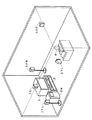
図10は、このホームシアターシステムにおける電子機器およびスピーカの配置の例を示すものである。すなわち、この図10の例においては、視聴者4の正面には、モニター受像機1が設けられると共に、その近傍に、映画のコンテンツが記録されたDVD(Digital Video Disc)を再生するDVDプレーヤ2が設置され、DVDプレーヤ2の映像信号出力端子が、モニター受像機1の映像信号入力端子に接続され、映画の画像がモニター受像機1の画面に映出されるようにされている。
【0004】
そして、この例のDVDプレーヤ2は、フロント2チャンネル、リア2チャンネル、センターチャンネル、低音専用チャンネルからなる6チャンネルのオーディオ信号出力端子を備え、各チャンネルのオーディオ信号出力端子は、各チャンネル用のスピーカ3FR,3FL,3RR,3RL,3C,3Wと接続される。
各チャンネル用のスピーカは、例えば次のように配置される。
【0005】
視聴者4の前方において、モニター受像機1の左右両サイドの、モニター受像機1を中心とした等距離の位置には、フロント右チャンネル用スピーカ3FRと、フロント左チャンネル用スピーカ3FLが設置される。また、モニター受像機1の上(あるいは下でもよい)には、センタチャンネル用スピーカ3Cが設置される。また、視聴者4のやや後方の左右両サイドで、視聴者4の耳の位置よりも高い位置には、リア右チャンネル用スピーカ3RRと、リア左チャンネル用スピーカ3RLとが設置される。さらに、低音専用チャンネル用スピーカ3Wが、この例では、モニター受像機1の脇に設置されている。なお、この低音専用チャンネル用スピーカ3Wの設置位置は、任意の位置でよい。
【0006】
DVDプレーヤ2の各オーディオ信号出力端子と、各チャンネル用のスピーカ3FR,3FL,3RR,3RL,3C,3Wとの接続は、図10では図示を省略したがが、スピーカケーブルと呼ばれる接続用線材が用いられて行なわれる。ここで、オーディオ信号出力端子は、プラス側端子部とマイナス側端子部の2個の端子部からなり、また、同様に、スピーカ端子も、プラス側端子部とマイナス側端子部の2個の端子部からなる。
【0007】
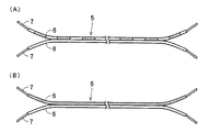
この接続用線材5は、前記プラス、マイナスの2個の端子部に対応して、図11(A)および図11(B)に示すように、複数本の細い銅線からなる銅線束がビニルなどからなる被覆部材6により被覆されたものが、2本、被覆の部分で一体化されて対とされて構成されている。
【0008】
この接続用線材5は、通常は、両端において、2本の被覆部分が図11(A)および図11(B)に示すように分離され、その分離された部分の先端部の被覆部材6が剥がされて、それぞれ銅線束が露呈され、その露呈された銅線束先端部7で、オーディオ信号出力端子またはスピーカの端子のそれぞれの2個の端子部と接続される。銅線束先端部分7は、予め半田により銅線束が一体化されている場合もある。
【0009】
接続用線材5は、電子機器のオーディオ信号出力端子とスピーカの2個の端子部のプラス、マイナスの極性を誤りなく接続することができるように、プラスとマイナスの極性に応じて、2本の銅線束のそれぞれの被覆部材6が、図11(A)のように、異なる模様とされたり、また、図11(B)に示すように、色分けされたりしている。
【0010】
この接続用線材5は、電子機器本体の複数個のオーディオ信号出力端子のそれぞれと、複数個のスピーカのそれぞれの端子との接続に全て同じものが用いられる。その接続方法としては、従来は、接続用線材の両端の、対の銅線束先端部7を、電子機器のオーディオ信号出力端子やスピーカの端子に巻き付ける方法と、端子に挟み込むようにする方法とが、従来一般に、用いられている。この場合、接続用線材5の被覆部材6の模様や、色分けにより、プラス側端子部とマイナス側端子部とに誤りなく、接続用線材が接続されるように接続者により注意が払われる。
【0011】
図12は、前者の方法により、電子機器のオーディオ出力端子に、接続用線材5の露呈した銅線束先端部7を巻き付けて接続した状態の例を示すものである。この方法の場合の電子機器のオーディオ出力端子やスピーカの端子は、接続用線材5の露呈した銅線束先端部7の部分を巻き付けることができるような形状を有し、巻き付け後の銅線束先端部7の部分を端子に固定することができるようにするためのねじ込み部8などが取り付けられている。
【0012】
また、図13は、後者の方法により、電子機器のオーディオ出力端子に、接続用線材5の露呈した銅線束先端部7を挟み込んで接続した状態の例を示すものである。この方法における電子機器のオーディオ出力端子やスピーカの端子は、孔9に挿入された接続用線材5の露呈した銅線束先端部7の部分を、例えばバネ部材による弾性変移する端子兼用の金属片により挟持させる構造を備える。
【0013】
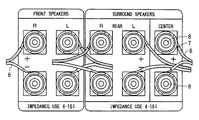
なお、電子機器の多チャンネルのオーディオ信号出力端子は、その電子機器の筐体の後ろ側のバックパネル面において、従来は、図12あるいは図13のように、各オーディオ信号出力端子が接続されるスピーカの実際の配置位置に関係なく、フロント左右チャンネル用、リア左右チャンネル用などというように、それぞれまとめられ、さらに適宜の位置にセンタチャンネル用や低音専用チャンネル用などが配置されたものとなっている。
【0014】
【発明が解決しようとする課題】
ところで、上述したように、従来は、ホームシアターシステムのような多チャンネルオーディオの場合で、接続するスピーカ数が多い場合であっても、接続用線材としては、同じ線材が用いられている。このため、どの線材がどのチャンネル用であるかが、判別できない。
【0015】
また、従来は、ホームシアターシステム用スピーカであっても、どのスピーカがどのチャンネル用なのかが表示されていなかったり、表示されていても、それが判りにくかった。特に、複数チャンネル用として、同種のスピーカが用いられている場合には、表示がされていても判り難いことが多々あった。
【0016】
そこで、従来は、スピーカを設置する前に、スピーカと電子機器との両者を近くに置いて、互いのチャンネルを確認しながら、接続用線材によって接続を行い、その後、スピーカを所定の位置に設置する方法や、スピーカを所定の位置に設置した後に、スピーカまたは電子機器の一方と接続した接続用線材をたぐりながら、スピーカまたは電子機器の他方に導き、その端子に接続するなどの方法が用いられていた。
【0017】
しかし、いずれの方法の場合でも、どの線材がどのチャンネル用であるかを、接続用線材をたぐりながら確認する必要があり、非常に厄介である。このため、接続するチャンネルを間違えてしまうおそれがあった。
【0018】
また、接続用線材の対の銅線束の被覆部材6は、プラスとマイナスの2極性を区分けするために、色分けなどがなされているが、どちらの色の被覆部材6で被覆された銅線を、いずれの極性に接続するかは使用者の任意であるため、接続用線材5と電子機器のオーディオ出力端子との接続におけるプラス、マイナスの極性と、接続用線材5とスピーカの端子との接続とにおける、プラス、マイナスの極性とが逆になってしまうおそれもあった。
【0019】
また、従来の電子機器のオーディオ信号出力端子は、前述したように、各チャンネル用のスピーカの実際の配置位置に対応するように考慮されていなかったので、オーディオ信号出力端子から接続用線材5を、スピーカ配置位置に応じて導出すると、複数本の線材が交錯し、どの線材がどのチャンネルの出力端子に接続されているかの整理がしにくくなり、それぞれの線材と、各チャンネル用のスピーカの端子との実際の接続時に、接続者が混乱を生じるおそれがあった。
【0020】
例えば、図12、図13のように、フロント左右チャンネル用オーディオ信号出力端子が、電子機器のバックパネルの左側に設けられ、リア左右チャンネル用オーディオ信号出力端子が右側に設けられていた場合、各チャンネルのスピーカの配置位置に応じて、電子機器のオーディオ信号出力端子に接続された接続用線材が導出されると、図14に示すように、フロント左チャンネル用スピーカに接続される接続用線材5FLは、リア左右チャンネル用オーディオ信号出力端子を跨いで電子機器から誘導され、また、リア右チャンネル用スピーカに接続される接続用線材5RRは、フロント左右チャンネル用オーディオ信号出力端子を跨いで電子機器から誘導されるので、これら2本の接続用線材が互いに交差することになり、線材の整理がしにくくなる。
【0021】
しかも、図14の交差部分7cに示すように、それぞれの接続用線材5の銅線束先端部7が接触して短絡する状態になると、電子機器に故障を生じさせてしまうおそれもある。
【0022】
また、フロント右チャンネル用オーディオ信号出力端子に接続された接続用線材5FRと、リア右チャンネル用オーディオ信号出力端子に接続された接続用線材5RRとは、電子機器の正面側から見て、それぞれ電子機器の右側から誘導されるようになるが、接続用線材は、全く同じものであるので、それらのチャンネル用スピーカに導かれる途中で、交錯してしまい、どちらのスピーカに接続すれば良いか、接続者は、混乱を生じる。この混乱は、フロント左チャンネルと、リア左チャンネルと、センタチャンネルとの間においても同様に生じる。
【0023】
また、従来の電子機器のオーディオ信号出力端子は、前述したように、各チャンネル用のスピーカの実際の配置位置に対応するように考慮されていなかったので、オーディオ信号出力端子が設けられる電子機器のバックパネル面に、図12、図13、図14に示したように、それらのチャンネルの名前が表示されていたとしても、マルチチャンネルオーディオシステムに精通していない使用者の場合には、それぞれのチャンネルのオーディオ信号出力端子に接続されたスピーカを、どの位置に設置するかについて、混乱を生じるおそれもあった。
【0024】
また、例えば、ホームシアターシステム用などのように、特定の目的に使用される場合、製造者は、同種のスピーカを多チャンネルに使用する場合でも、最良の音場で音響再生が行われるように、フロント左右チャンネル用、リア左右チャンネル用、センタチャンネル用など、それぞれのチャンネル用に調整して出荷することがある。
【0025】
しかし、従来は、前述したように、どのスピーカがどのチャンネル用なのかが表示されていなかったり、表示されていても、それが判りにくかったので、接続者が、製造者が意図したチャンネル用とは異なるスピーカを接続してしまうことは多々ある。すると、それぞれの配置位置のスピーカから、所期の音声が出力されていない状態になり、これでは、本来のメディアソースを忠実に再現できないため、機器購入者に対して、生産者が意図した音場を十分に楽しんでもらうことができないおそれがある。
【0026】
確実に、そのような音場を再現するためには、各チャンネルごとに、電子機器のオーディオ出力端子と、対応するチャンネルのスピーカとを確認すると共に、プラス側端子部とマイナス側端子部を確認し、また、線材が隣の端子と短絡しないように注意し、さらに、各スピーカをどこに配置すれば良いのかを確認しながら、接続作業を行わなければならず、非常に煩わしく、非常に時間が掛かるという問題がある。
【0027】
この発明は、以上の問題点を一掃して、オーディオ出力チャンネル数に関係なく、簡単で、判りやすく、スピーカとオーディオ信号出力端子を有する電子機器とを接続することができるようにすることを目的とする。
【0028】
【課題を解決するための手段】
本発明においては、オーディオシステムであって、視聴位置の前方中央に配置されるセンタスピーカ、該視聴位置の前方のセンタスピーカより下方に配置される低音スピーカ、該視聴位置に対して右側に配置される右スピーカ、及び該視聴位置に対して左側に配置される左スピーカと、センタスピーカ、低音スピーカ、右スピーカ及び左スピーカに対してそれぞれに対応するチャンネルのオーディオ信号を出力するための出力端子を備える電子機器と、前記電子機器と、センタスピーカ、低音スピーカ、右スピーカ及び左スピーカとの間をそれぞれ接続するための導体部を備える接続用線材とを有し、電子機器は、センタスピーカに対応する出力端子が中央に配置され、低音スピーカに対応する出力端子がセンタスピーカに対応する出力端子の下方に配置され、右スピーカに対応する出力端子がセンタスピーカに対応する出力端子の右側に配置され、左スピーカに対応する出力端子がセンタスピーカに対応する出力端子の左側に配置され、接続用線材の少なくとも一端部は、対をなす極性の2本の導体部が接続される第1のコネクタ部の構造とされるとともに、電子機器の出力端子は、第1のコネクタ部が嵌合される第2のコネクタ部の構造とされ、第2のコネクタ部は、第1のコネクタが嵌合される凹部と、凹部内に底面から突設された対をなす極性の2本の接続用ピンと、凹部の側面の2本の接続用ピンから等距離の位置に凹部の内側方向に所定高さに突出した位置規制部材とを備え、第1のコネクタ部は、導体部に接続されて対をなす極性の2本の接続用ピンと嵌合する2個の嵌合孔と、2個の嵌合孔から等距離の位置で極性合わせ用の位置規制部材に対応する位置に該位置規制部材よりも深い第1の溝と、2個の嵌合孔から等距離の位置で該第1の溝とは反対側の位置に該位置規制部材よりも浅い第2の溝とを備える。
【0029】
これにより、センタスピーカとその下方に配置される低音スピーカに対応する電子機器の出力端子がそれぞれ上下に配置されており、左右のスピーカに対応する出力端子がそれぞれ左右に配置さているので、各チャンネルの接続用線材が出力端子部において、交差することが殆どなく、整理される状態になると共に、電子機器と各スピーカとの間を接続用線材によって接続する際に、コネクタの挿入方向を容易に把握させることができ、配置されたスピーカと出力端子との対応が容易に付くので、接続作業が容易になる。
【0030】
また、視聴位置の前方中央に配置されるセンタスピーカ、該視聴位置の前方のセンタスピーカより下方に配置される低音スピーカ、該視聴位置に対して右側に配置される右スピーカ、及び該視聴位置に対して左側に配置される左スピーカに対してそれぞれに対応するチャンネルのオーディオ信号を出力するための出力端子を備える電子機器であって、センタスピーカに対応する出力端子が中央に配置され、低音スピーカに対応する出力端子がセンタスピーカに対応する出力端子の下方に配置され、右スピーカに対応する出力端子がセンタスピーカに対応する出力端子の右側に配置され、左スピーカに対応する出力端子がセンタスピーカに対応する出力端子の左側に配置され、少なくとも一端が対をなす極性の2本の導体部が接続される第1のコネクタ部の構造とされる接続用線材を介して、出力端子と、センタスピーカ、低音スピーカ、右スピーカ及び左スピーカとの間をそれぞれ接続され、出力端子は、第1のコネクタ部が嵌合される第2のコネクタ部の構造とされ、第2のコネクタ部は、第1のコネクタが嵌合される凹部と、凹部内に底面から突設された対をなす極性の2本の接続用ピンと、凹部の側面の2本の接続用ピンから等距離の位置に凹部の内側方向に所定高さに突出した位置規制部材とを備え、第1のコネクタ部は、導体部に接続されて対をなす極性の2本の接続用ピンと嵌合する2個の嵌合孔と、2個の嵌合孔から等距離の位置で極性合わせ用の位置規制部材に対応する位置に該位置規制部材よりも深い第1の溝と、2個の嵌合孔から等距離の位置で該第1の溝とは反対側の位置に該位置規制部材よりも浅い第2の溝とを備える。
【0031】
これにより、センタスピーカとその下方に配置される低音スピーカに対応する電子機器の出力端子がそれぞれ上下に配置されており、左右のスピーカに対応する出力端子がそれぞれ左右に配置さているので、各チャンネルの接続用線材が出力端子部において、交差することが殆どなく、整理される状態になると共に、電子機器と各スピーカとの間を接続用線材によって接続する際に、コネクタの挿入方向を容易に把握させることができ、配置されたスピーカと出力端子との対応が容易に付くので、接続作業が容易になる。
【0043】
【発明の実施の形態】
以下、この発明の実施の形態を、図を参照しながら説明する。
【0044】
以下に説明する実施の形態は、図10に示したホームシアターシステムに、この発明を適用した場合のものであり、前述したように、フロント2チャンネル、リア2チャンネル、低音専用チャンネル、センターチャンネルからなる6チャンネルオーディオシステムの場合である。そして、オーディオ信号出力端子を備える電子機器は、前述と同様に、DVDプレーヤの場合である。
【0045】
図1は、この実施の形態におけるオーディオ信号出力端子を備える電子機器としてのDVDプレーヤ10と、図Aに示したように配置される各チャンネルのスピーカ3FR,3FL,3RR,3RL,3C,3Wとの接続方法を説明するための図である。
【0046】
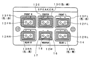
図1に示すように、DVDプレーヤ10には、そのバックパネルに、6チャンネル分のオーディオ信号出力端子形成部11が設けられる。このオーディオ信号出力端子形成部11には、この実施の形態では、その拡大図である図2にも示すように、各チャンネルのオーディオ信号出力端子は、プラグイン方式の6個(6チャンネル)のソケット12FR,12FL,12RR,12RL,12C,12Wとして形成されている。
【0047】
ソケット12FRはフロント右チャンネルオーディオ信号の出力端子、ソケット12FLはフロント左チャンネルオーディオ信号の出力端子、ソケット12RRはリア右チャンネルオーディオ信号の出力端子、ソケット12RLはリア左チャンネルオーディオ信号の出力端子、ソケット12Cはセンタチャンネルオーディオ信号の出力端子、ソケット12Wは低音専用チャンネルオーディオ信号の出力端子、をそれぞれ形成している。
【0048】
これらの6個のソケット12FR,12FL,12RR,12RL,12C,12Wは、3個ずつ、上下2列に形成されているが、この実施の形態では、図1および図2に示すように、各チャンネル用のスピーカ3FR,3FL,3RR,3RL,3C,3Wの配置位置に全く対応するように配置されている。なお、図1および図2は、バックパネル側からオーディオ信号出力端子形成部を見た図であるので、視聴者4側から見た場合に対して、左右が逆となっている。
【0049】
すなわち、図2に示すように、フロント右チャンネル用ソケット12FRおよびリア右チャンネル用ソケット12RRは、オーディオ信号出力端子形成部11の左側の上下の2個のソケットとして配置されている。また、フロント左チャンネル用ソケット12FRおよびリア左チャンネル用ソケット12RRは、オーディオ信号出力端子形成部11の右側の上下の2個のソケットとして配置されている。さらに、センタチャンネル用ソケット12Cは、中央上のソケットとして配置されている。また、低音専用チャンネル用ソケット12Wは、中央下のソケットとして配置されている。
【0050】
なお、フロントチャンネル用ソケットと、リアチャンネル用ソケットの上下関係は逆であってもよい。
【0051】
以上のように、各出力チャンネルのソケットが、各チャンネルのスピーカの実際の配置位置に対応して配置されているので、後述する各チャンネル用の接続用線材21FR,21FL,21RR,21RL,21C,21Wにより、各ソケット12FR,12FL,12RR,12RL,12C,12Wと、各出力チャンネル用のスピーカ3FR,3FL,3RR,3RL,3C,3Wとを接続した場合には、接続用線材同士が、上下左右に絡まないようになる。
【0052】
すなわち、例えばフロント右チャンネル用と、リア右チャンネル用の接続用線材21FRと21RRとは、それぞれ他のチャンネル用のオーディオ信号出力端子部分を跨ぐことなく、DVDプレーヤ10の正面からみて右側に導かれ、また、フロント左チャンネル用と、リア左チャンネル用の接続用線材21FLと21RLとは、それぞれ他のチャンネル用のオーディオ信号出力端子部分を跨ぐことなく、DVDプレーヤ10の正面からみて左側に導かれ、左、右チャンネル用の接続用線材が、互いに交錯することが防止される。
【0053】
また、センタチャンネル用の接続用線材21Cと、低音専用チャンネル用の接続用線材21Wとは、図10のスピーカ設置位置に応じて、DVDプレーヤ10からそれらのチャンネル用接続用線材を導く場合には、DVDプレーヤ10の上側と、下側に導かれることになり、これらの接続用線材も、他の接続用線材と交錯することが防止される。
【0054】
次に、この実施の形態では、6チャンネルの各オーディオ信号出力チャンネルを、色分けにより、DVDプレーヤと、スピーカと、接続用線材との間で、統一的に識別できるようにして、接続者による接続作業を、容易かつ誤りなく、行えるようにしている。
【0055】
この実施の形態では、例えば、
フロント右チャンネル:赤色
フロント左チャンネル:白色
リア右チャンネル :黄色
リア左チャンネル :青色
センタチャンネル :緑色
低音専用チャンネル :黒色
により、色分けするようにする。
【0056】
まず、DVDプレーヤの各出力チャンネルの出力端子は、この実施の形態では、次のようにして色分けにより互いに識別できるようにしている。すなわち、図2に示すように、DVDプレーヤのバックパネル14の、各チャンネルのソケット取り付け部の周辺部分には、それぞれ上記のような色に選定されたシート13FR,13FL,13RR,13RL,13Cが張り付けられている。この例では、各シート13FR,13FL,13RR,13RL,13Cのそれぞれには、各出力チャンネルの導体の極性が印刷表示されている。
【0057】
なお、図2の例では、低音専用チャンネル用ソケット12Wには色分け用のシートは貼り付けなかったが、これは、この例では、低音専用チャンネルは黒色として色分けすることとしており、この例のバックパネル14は黒色であるので、色分け用のシートの貼り付けを省略したものである。もしも、バックパネル14と低音専用チャンネルに割り当てる色とが異なる場合には、低音専用チャンネル用ソケット12Wの部分にも色分け用のシートを貼り付けるのは勿論である。
【0058】
また、各ソケット12FR,12FL,12RR,12RL,12C,12Wが、どの出力チャンネルであるかを、ユーザに知らしめるために、図2においては、バックパネル14の各チャンネルのソケットの近傍には、予め、各出力チャンネルの名称が印刷されている。しかし、この出力チャンネルの名称は、この例のようにバックパネル14に印刷するのではなく、各出力チャンネルの色分け表示用のシート13FR,13FL,13RR,13RL,13C,13W(13Wは低音専用チャンネル用シート)に、印刷するようにしても良い。
【0059】
なお、各ソケット12FR,12FL,12RR,12RL,12C,12Wの構成部品を、それぞれのチャンネル用の色を呈するものとするように構成することもできるが、その場合には、6色のソケットが必要となってコストアップとなってしまう。この点、この実施の形態のように、色の異なるシート13FR,13FL,13RR,13RL,13C,13Wを用いるようにすれば、コストアップを低く抑えることができるというメリットがある。
【0060】
なお、バックパネル14に、チャンネルの色分け表示用のシートを貼り付ける代わりに、バックパネル14のシートの貼り付け部分を、予め、6色の印刷により形成しておくようにしても良い。
【0061】
次に、オーディオ信号出力端子と、接続用線材との接続態様および接続用線材の色分けに付いて説明する。
【0062】
この実施の形態では、電子機器のオーディオ信号出力端子と、接続用線材との接続は、従来のような巻き付け方式や、挟み込み方式ではなく、プラグイン方式を採用する。すなわち、この例では、オーディオ信号出力端子側を、前述したようなソケットの構成とすると共に、接続用線材21FR,21FL,21RR,21RL,21C,21Wの一方の端部側は、前記ソケットに嵌合するプラグの構成とする。
【0063】
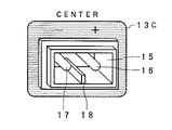
前述したDVDプレーヤ10の6チャンネルのオーディオ信号出力端子としてのソケット12FR,12FL,12RR,12RL,12C,12Wは、図3にも示すように、後述する接続用線材側のプラグが嵌合する凹部15を備える。そして、この凹部15には、各オーディオ信号出力端子のプラス側導体およびマイナス側導体が接続されている2本の導体ピン16、17が、水平に並んだ状態で、凹部15の底部から突き出すように設けられている。
【0064】
さらに、凹部15の下側の側面には、後述する接続用線材側のプラグが、プラス、マイナスの極性を誤って、ソケット内に挿入されないようにするための位置規制部材としてのリブ18が設けられている。このリブ18は、凹部15の下側の側面において、2本の導体ピン16、17の間の丁度中央部に相当する位置に設けられている。
【0065】
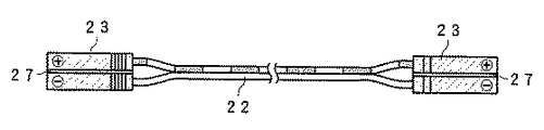
一方、接続用線材21FR,21FL,21RR,21RL,21C,21Wのそれぞれは、図4にも示すように、線材本体22としては、従来例と同様に、複数本の細い銅線からなる銅線束がビニルなどからなる被覆部材により被覆されたものが、2本、被覆の部分で一体化されて対とされて構成されている。図示のように、この例では、線材本体22の被覆部材の色は、プラス、マイナスの極性を識別するために、2本の銅線束のそれぞれで、従来と同様に異なるものとされている。しかし、この実施の形態では、接続用線材本体22の被覆部材の色分けは必須ではない。
【0066】
そして、線材本体22の両端は、2本の被覆部分が図11(A)および図11(B)に示すように分離され、その分離された部分の先端部の被覆部材が剥がされて、それぞれ銅線束が露呈されるようにされる。しかし、この実施の形態の接続用線材21FR,21FL,21RR,21RL,21C,21Wにおいては、一方の端部は、前記ソケットに嵌合するプラグ23の構成とされ、2個の銅線束が、その内部の2個の導体部と接続されている。そして、このプラグ23の色が、後述するように、各オーディオ信号出力チャンネルに応じた色とされる。
【0067】
プラグ23の部分の構成は、接続用線材21FR,21FL,21RR,21RL,21C,21Wにおいて、色の点を除けば全く同一である。
【0068】
この例では、このプラグ23は、プラグの先端側から見た図である図5にも示すように、前記ソケットの導体ピン16、17と嵌合するジャック孔部24、25を備える。このジャック孔部24、25には、導体ピン16、17と電気的に接続されるプラス、マイナスの2個の導体部が構成している。そして、このジャック孔部24、25の導体部に、接続用線材22のプラス、マイナスの銅線束先端部のそれぞれが半田付けなどにより接続されている。
【0069】
この例のプラグ23は、接続用線材22のプラス、マイナスの銅線束先端部のそれぞれと、前記導体部とを半田付けなどにより接続した後、プラスチックにより、モールドされて形成されたものである。図5から判るように、このプラグ23は、プラスとマイナスの導体部に分離されているのではなく、一体的なものとされている。
【0070】
そして、この実施の形態においては、このプラグ23のプラスチック部分の色が、前述した各出力チャンネル用に合わせて、色分けされて、オーディオ信号出力端子との接続に用いられる。すなわち、プラグ23は、
フロント右チャンネル用の接続用線材21FRでは、赤色とされ、
フロント左チャンネル用の接続用線材21FLでは、白色とされ、
リア右チャンネル用の接続用線材21RRでは、黄色とされ、
リア左チャンネル用の接続用線材21RLでは、青色とされ、
センタチャンネル用の接続用線材21Cでは、緑色とされ、
低音専用チャンネル用の接続用線材21Wでは、黒色とされている。
【0071】
また、図4および図5の例においては、接続用線材22の2本の銅線束について、予めプラスと、マイナスとが決定されている。このため、プラグ23の先端部には、図4に示すように、その定められたプラス、マイナスの極性が刻印などにより表示されている。そして、この実施の形態では、プラグ23のプラス、マイナスの極性と、ソケットのプラス、マイナスの極性とが、前記ソケットのリブ18により、誤りなく接続されるように、考慮されている。
【0072】
すなわち、この例では、プラグ23には、図5に示すように、プラグ23の厚さ方向に、接続用線材のプラス、マイナスの2本の銅線束を区分けする位置に、溝26、27が上下に設けられているが、両溝26、27の深さを異ならせることにより、プラグ23が、プラス、マイナスの極性を誤って、ソケット内に挿入されないようにされている。
【0073】
この実施の形態では、プラグ23の下側の溝26は、ソケットのリブ18が嵌挿可能となる深さとされ、一方、上側の溝27は、ソケットのリブ18が入らず、リブ18とプラグ23とが衝突する深さとされている。
【0074】
したがって、この例では、図5の例のプラグ23の上側には、プラス、マイナスの表示がされているので、接続者は、プラグ23の、このプラス、マイナスの表示がされている側を上側として、オーディオ信号出力端子であるソケットに挿入すれば、プラグ23がソケットに挿入され、その状態では、プラグ23に表示されたプラス、マイナスの極性と、ソケットのプラス、マイナスの極性が一致する。
【0075】
一方、プラグ23の上下が逆の場合には、リブ28のために、プラグ23は、ソケットに挿入できない。これにより、接続者が、接続用線材側のプラグ23のプラス、マイナスの極性を誤って、ソケット内に挿入することが防止される。
【0076】
次に、接続用線材21FR、21FL,21RR,21RL,21C,21Wと、それぞれの出力チャンネル用のスピーカ3FR,3FL,3RR,3RL,3C,3Wとの接続について説明する。
【0077】
この例では、接続用線材21FR、21FL,21RR,21RL,21C,21Wと、スピーカ3FR,3FL,3RR,3RL,3C,3Wとのそれぞれは、従来例で説明した挟み込み法により行う。しかしながら、この実施の形態では、スピーカが予め各出力チャンネル用ごとに特定される点と、各出力チャンネルごとの色分けを用いることにより、接続の容易化を図っている。
【0078】
すなわち、図4に示すように、各接続用線材21FR、21FL,21RR,21RL,21C,21Wの、各スピーカ3FR,3FL,3RR,3RL,3C,3Wとの接続側は、従来と同様に、2本の被覆部分が図示のように分離され、その分離された部分の先端部の被覆部材が剥がされて、それぞれ銅線束が露呈され、その露呈された銅線束先端部28で、スピーカの端子と接続される。
【0079】
この実施の形態では、前述したように、一方の端部はプラグ23の構成とされており、プラスとマイナスの極性が一義的に定められている。そこで、この接続用線材のスピーカ端子との接続側においては、分離された2本の被覆部分のプラス、マイナスの極性を明確にするために、例えばプラス側には白色の熱収縮チューブ31が装着され、マイナス側には黒色の熱収縮チューブ32が装着されている。
【0080】
さらに、それぞれの接続用線材が、いずれのオーディオ信号出力チャンネル用のものであるかを識別するために、接続用線材本体22の、2本の被覆部分が一体化されている部分には、その出力チャンネルの色の熱収縮チューブ33が装着されている。
【0081】
一方、各チャンネル用のスピーカ3FR,3FL,3RR,3RL,3C,3Wのそれぞれには、その出力チャンネルの名称と、極性とが印刷された、各出力チャンネルに対応して色分けされたラベルが、各スピーカの端子の近傍に貼り付けられている。
【0082】
図6は、フロント右チャンネル用のスピーカ3FRの裏面側を示す図であり、挟み込み方式のスピーカ端子41、42が設けられている。そして、これらスピーカ端子41、42の近傍に、フロント右チャンネルを示す「Front R」の文字と、プラス、マイナスの表示とが印刷された赤色のラベル43が、貼り付けられて設けられている。
【0083】
なお、各ラベルのプラスとマイナスの表示部分は、接続用線材の極性識別用チューブ31、32の色に対応して、白色、黒色で表示されている。
【0084】
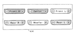
このラベル43等は、各チャンネルのスピーカ3FR,3FL,3RR,3RL,3C,3Wのそれぞれに、予め貼り付けておくようにしても良いが、図7に示すように、6チャンネル分のラベルが印刷され、かつ、分離して剥がして、貼り付けることができるのりつけラベルシート44を接続者に提供し、それぞれのラベルを、接続者に、それぞれのチャンネル用のスピーカに貼り付けて使用するようにすることもできる。
【0085】
以上のように構成された、DVDプレーヤ10のオーディオ信号出力端子部11と、接続用線材21FR,21FL,21RR,21RL,21C,21Wのそれぞれと、各チャンネルのスピーカ3FR,3FL,3RR,3RL,3C,3Wとを用いた、各チャンネルのオーディオ信号出力端子とスピーカとの接続の手順の例を、次に説明する。
【0086】
▲1▼DVDプレーヤのオーディオ信号出力端子としてのソケット部分のシートの色と同色の、接続用線材のプラグ23を、ソケットに挿入する。挿入できたことにより、プラス、マイナスの極性は自動的に合致する。
【0087】
▲2▼スピーカのチャンネル名称表示ラベルの色と同じ色の熱収縮チューブ33が装着されている接続用線材の2個の先端部28を、それぞれの極性識別用熱収縮チューブ31、32により、極性を確かめ、かつ、ラベルのプラス、マイナスの表示色を確かめながら、そのスピーカのプラス側端子部、マイナス側端子部に差し込む。
【0088】
▲3▼スピーカのチャンネル名称表示ラベルに応じた位置に、そのスピーカを配置する。
【0089】
以上により、接続者は、オーディオ信号出力端子を備える電子機器と、複数個のスピーカとを、チャンネルを間違えることなく、かつ、極性を間違えることなく、接続することが容易にできると共に、各チャンネルのスピーカを正しい位置に設置することができる。
【0090】
[他の実施の形態]
以上の実施の形態では、接続用線材の一端側にのみ、プラグ23が設けられ、他端側は、従来と同様の挟み込み法により、スピーカと接続するようにしたが、図8に示すように、接続用線材の両端部を、プラグ23の構成とするようにすることもできる。
【0091】
この実施の形態の場合には、接続用線材の両端部の2個のプラグ23は、それが使用される出力チャンネル用の同一の色とされる。
【0092】
そして、スピーカの端子は、図9に示すように、図2および図3に示した、オーディオ信号出力端子のソケットと同様の構造のソケット45の構成とされる。そして、図9の例では、そのソケット45の近傍に、チャンネル名称および極性が印刷されたラベル43が貼り付けられる。このラベル43の代わりに、図2のシート13FR,13FL,13RR,13RL,13C,13Wと同様のシートを、スピーカのソケット45の周囲にも貼り付けるようにしても良い。その場合には、そのシートには、チャンネル名称および極性を示す印刷を施すようにするとよい。
【0093】
この実施の形態の場合には、オーディオ信号出力端子を備える電子機器とスピーカとの接続手順の前記▲2▼においては、スピーカのチャンネル名称表示ラベルと同じ色のプラグ23を有する接続用線材の当該プラグ23を、スピーカのソケット45に挿入するだけで良い。この場合には、極性は、プラグ23がソケット45に挿入された時に正しい状態になる。
【0094】
[その他の変形例]
以上の実施の形態では、接続用線材側にジャック孔部を備えるプラグを設け、オーディオ信号出力端子やスピーカ端子を、ソケットの構造としたが、接続用線材側にソケットと同様の機構を設け、オーディオ信号出力端子やスピーカ端子側にプラグと同様の機構を設けるようにしても良い。
【0095】
また、プラグ23の部分の構成と、ソケットの部分の構成は、上述の実施の形態の構成に限らないことはいうまでもない。
【0096】
なお、実施の形態の接続用線材は、スピーカケーブルだけでなく、対の極性を識別するためのものとしても適用可能である。
【0097】
【発明の効果】
以上説明したように、この発明によれば、センタスピーカとその下方に配置される低音スピーカに対応する電子機器の出力端子がそれぞれ上下に配置されており、左右のスピーカに対応する出力端子がそれぞれ左右に配置さているので、各チャンネルの接続用線材が出力端子部において、交差することが殆どなく、整理される状態になると共に、電子機器と各スピーカとの間を接続用線材によって接続する際に、コネクタの挿入方向を容易に把握させることができ、配置されたスピーカと出力端子との対応が容易に付くので、接続作業が容易になり、かくして簡単で判りやすく、スピーカと出力端子を有する電子機器とを接続させることができる。
【0098】
また、極性が問題となる出力端子と、接続用線材との接続において、極性を考慮せずに、接続を行うことができるようになる。
【0099】
また、マルチチャンネルオーディオシステムにおいて、オーディオ信号出力端子を備える電子機器と、複数個のスピーカとを、チャンネルを間違えることなく、かつ、極性を間違えることなく、接続することが容易にできると共に、各チャンネルのスピーカを正しい位置に設置することができる。
【図面の簡単な説明】
【図1】この発明によるマルチチャンネルオーディオシステムの実施の形態の全体の構成を説明するための図である。
【図2】実施の形態の電子機器のオーディオ信号出力端子形成部の構成例を示す図である。
【図3】図2の要部の説明のための図である。
【図4】実施の形態の接続用線材の構成例を示す図である。
【図5】図4の要部を説明するための図である。
【図6】実施の形態のスピーカ端子近傍を示す図である。
【図7】この発明による実施の形態を説明するための図である。
【図8】他の実施の形態の接続用線材の構成例を示す図である。
【図9】他の実施の形態のスピーカ端子近傍を示す図である。
【図10】マルチチャンネルオーディオシステムの概要を説明するための図である。
【図11】従来の接続用線材を説明するための図である。
【図12】従来の接続用線材を用いたオーディオ信号出力端子との接続態様の一例を説明するための図である。
【図13】従来の接続用線材を用いたオーディオ信号出力端子との接続態様の他の例を説明するための図である。
【図14】従来の接続用線材を用いたオーディオ信号出力端子との接続態様の不具合を説明するための図である。
【符号の説明】
3FR…フロント右チャンネル用スピーカ、3FL…フロント左チャンネル用スピーカ、3RR…リア右チャンネル用スピーカ、3RL…リア左チャンネル用スピーカ、3C…センタチャンネル用スピーカ、3W…低音専用チャンネル用スピーカ、10…DVDプレーヤ、11…オーディオ信号出力端子部、12FR…フロント右チャンネルオーディオ信号出力端子、12FL…フロント左チャンネルオーディオ信号出力端子、12RR…リア右チャンネルオーディオ信号出力端子、12RL…リア左チャンネルオーディオ信号出力端子、12C…センタチャンネルオーディオ信号出力端子、12W…低音専用チャンネルオーディオ信号出力端子、21FR,21FL,21RR,21RL,21C,21W…接続用線材、23…プラグ[0001]
BACKGROUND OF THE INVENTION
The present invention uses a large number of speakers such as a home theater system.RuoAudio system, especially in this systemOutThe present invention relates to an invention for connecting a power device and a speaker. Also suitable for use in this systemNadeElectronic device with power terminalIn a vesselRelated.
[0002]
[Prior art]
In recent years, multi-channel speaker systems have emerged that allow a sound effect similar to an effective sound output in a movie theater to be obtained when watching a movie at home. For example, in a so-called home theater system, a 6-channel speaker including a channel dedicated to low sound output and a center channel is driven.
[0003]
FIG. 10 shows an example of the arrangement of electronic devices and speakers in this home theater system. That is, in the example of FIG. 10, a
[0004]
The
The speakers for each channel are arranged as follows, for example.
[0005]
A front right channel speaker 3FR and a front left channel speaker 3FL are installed in front of the
[0006]
The connection between each audio signal output terminal of the
[0007]
As shown in FIGS. 11 (A) and 11 (B), the connecting
[0008]
In this connecting
[0009]
The connecting
[0010]
The same connecting
[0011]
FIG. 12 shows an example of a state in which the copper wire bundle
[0012]
FIG. 13 shows an example of a state in which the
[0013]
Note that the multi-channel audio signal output terminal of an electronic device is conventionally connected to each audio signal output terminal on the back panel surface on the rear side of the casing of the electronic device as shown in FIG. 12 or FIG. Regardless of the actual position of the speakers, the front left and right channels, rear left and right channels, etc. are grouped together, and the center channel and the bass dedicated channel are arranged at appropriate positions. Yes.
[0014]
[Problems to be solved by the invention]
By the way, as described above, conventionally, in the case of multi-channel audio such as a home theater system, even when a large number of speakers are connected, the same wire is used as a connecting wire. For this reason, it cannot be determined which wire is for which channel.
[0015]
Conventionally, even if it is a speaker for a home theater system, which speaker is for which channel is not displayed or displayed, it is difficult to understand. In particular, when the same type of speaker is used for a plurality of channels, it is often difficult to understand even if the display is performed.
[0016]
Therefore, conventionally, before installing the speaker, place both the speaker and the electronic device close to each other, check each other's channels and connect with the connecting wire, and then install the speaker in a predetermined position. Or after the speaker is installed at a predetermined position, it is guided to the other side of the speaker or electronic device while being connected to one of the speakers or the electronic device and connected to the terminal. It was.
[0017]
However, in any of the methods, it is necessary to check which wire is for which channel while checking the connecting wire, which is very troublesome. For this reason, there is a possibility that a channel to be connected is mistaken.
[0018]
In addition, the covering
[0019]
In addition, since the audio signal output terminal of the conventional electronic device is not considered so as to correspond to the actual arrangement position of the speaker for each channel as described above, the connecting
[0020]
For example, as shown in FIGS. 12 and 13, when the front left and right channel audio signal output terminals are provided on the left side of the back panel of the electronic device and the rear left and right channel audio signal output terminals are provided on the right side, When the connecting wire connected to the audio signal output terminal of the electronic device is derived according to the arrangement position of the speaker of the channel, as shown in FIG. 14, the connecting wire 5FL connected to the front left channel speaker is shown. Is guided from the electronic device across the rear left and right channel audio signal output terminals, and the connecting wire 5RR connected to the rear right channel speaker is from the electronic device across the front left and right channel audio signal output terminals. Because they are guided, these two connecting wires cross each other, and the arrangement of the wires It becomes Nikuku.
[0021]
In addition, as shown in the intersecting portion 7c in FIG. 14, if the tip ends 7 of the copper wire bundles of the respective connecting
[0022]
Further, the connection wire 5FR connected to the front right channel audio signal output terminal and the connection wire 5RR connected to the rear right channel audio signal output terminal are respectively electronic as viewed from the front side of the electronic device. Although it comes to be guided from the right side of the device, the connecting wire is exactly the same, so it crosses in the middle of being guided to those channel speakers, which speaker should be connected, Connecters are confused. This confusion similarly occurs between the front left channel, the rear left channel, and the center channel.
[0023]
Further, as described above, the audio signal output terminal of the conventional electronic device has not been considered so as to correspond to the actual arrangement position of the speaker for each channel. Even if the names of those channels are displayed on the back panel surface as shown in FIGS. 12, 13, and 14, the users who are not familiar with the multi-channel audio system need to There is also a risk of confusion as to where the speaker connected to the audio signal output terminal of the channel is to be installed.
[0024]
In addition, for example, when used for a specific purpose, such as for home theater systems, the manufacturer can reproduce sound in the best sound field even when using the same type of speaker for multiple channels. It may be shipped after adjusting for each channel such as front left and right channel, rear left and right channel, and center channel.
[0025]
However, as described above, it has been difficult to understand which speaker is for which channel as described above, and even if it is displayed, it is difficult to understand. Often connect different speakers. As a result, the intended sound is not output from the speakers at the respective positions, and the original media source cannot be faithfully reproduced. You may not be able to fully enjoy the venue.
[0026]
To reliably reproduce such a sound field, check the audio output terminal of the electronic device and the speaker of the corresponding channel for each channel, and check the positive terminal and negative terminal. In addition, care must be taken not to short-circuit the wire with the adjacent terminal, and the connection work must be performed while confirming where to place each speaker, which is very cumbersome and very time consuming. There is a problem of hanging.
[0027]
SUMMARY OF THE INVENTION It is an object of the present invention to eliminate the above-described problems and make it possible to connect a speaker and an electronic device having an audio signal output terminal, regardless of the number of audio output channels. And
[0028]
[Means for Solving the Problems]
In the present invention, the audio system is a center speaker disposed in the front center of the viewing position, a bass speaker disposed below the center speaker in front of the viewing position, and disposed on the right side with respect to the viewing position. An output terminal for outputting an audio signal of a channel corresponding to each of the right speaker and the left speaker arranged on the left side with respect to the viewing position and the center speaker, the bass speaker, the right speaker, and the left speaker. And a connecting wire having a conductor for connecting each of the electronic device and the center speaker, the bass speaker, the right speaker, and the left speaker. The electronic device corresponds to the center speaker. Output terminal corresponding to the bass speaker is the output terminal corresponding to the bass speaker. Disposed below the output terminals corresponding to the right speaker are disposed on the right side of the output terminals corresponding to the center speaker, the output terminal corresponding to the left speaker is disposed on the left side of the output terminals corresponding to the center speakerAt least one end of the connecting wire has a structure of a first connector to which two pairs of polar conductors are connected, and the output terminal of the electronic device is fitted with the first connector. The second connector portion has a structure in which the second connector portion is connected to the concave portion into which the first connector is fitted, and two pairs of polarities that form a pair projecting from the bottom surface in the concave portion. And a position restricting member protruding at a predetermined height in the inner direction of the recess at a position equidistant from the two connection pins on the side surface of the recess, and the first connector portion is connected to the conductor portion. Two fitting holes for fitting with two connecting pins having a pair of polarities, and the position regulating member at a position corresponding to the position regulating member for polarity matching at a position equidistant from the two fitting holes A deeper first groove and a position opposite to the first groove at a position equidistant from the two fitting holes And a shallower second grooves than the position regulating member.
[0029]
As a result, the output terminals of the electronic devices corresponding to the center speaker and the bass speaker disposed below the center speaker are respectively disposed above and below, and the output terminals corresponding to the left and right speakers are respectively disposed on the left and right. In the output terminal portion, the connecting wire material hardly intersects and is arranged, and when connecting the electronic device and each speaker by the connecting wire material,You can easily grasp the insertion direction of the connector,Since the correspondence between the arranged speaker and the output terminal is easily attached, the connection work is facilitated.
[0030]
Further, a center speaker disposed in the front center of the viewing position, a bass speaker disposed below the center speaker in front of the viewing position, a right speaker disposed on the right side of the viewing position, and the viewing position On the other hand, an electronic device having an output terminal for outputting an audio signal of a channel corresponding to each of the left speaker arranged on the left side, the output terminal corresponding to the center speaker being arranged in the center, and a bass speaker Is arranged below the output terminal corresponding to the center speaker, the output terminal corresponding to the right speaker is arranged on the right side of the output terminal corresponding to the center speaker, and the output terminal corresponding to the left speaker is the center speaker. Placed on the left side of the output terminal corresponding toThe output terminal, the center speaker, the bass speaker, the right speaker, and the left speaker are connected via the connecting wire having the structure of the first connector portion to which the two conductor portions having polarities that are paired at least at one end are connected. And the output terminal has a structure of a second connector portion into which the first connector portion is fitted, and the second connector portion has a recess portion into which the first connector is fitted. A pair of polar connecting pins projecting from the bottom surface in the recess and a position protruding from the two connecting pins on the side surface of the recess at a predetermined height in the inward direction of the recess at the same distance The first connector portion is provided with a regulating member, and the first connector portion is equidistant from the two fitting holes and the two fitting holes that are connected to the two connecting pins having a polarity connected to the conductor portion. The position restricting member should be positioned at the position corresponding to the position restricting member for polarity matching. Also includes a deep first groove, and two from the fitting hole in a position equidistant from the first groove second shallower than said position regulating member on the opposite side position of the groove.
[0031]
As a result, the output terminals of the electronic devices corresponding to the center speaker and the bass speaker disposed below the center speaker are respectively disposed above and below, and the output terminals corresponding to the left and right speakers are respectively disposed on the left and right. In the output terminal portion, the connecting wire material hardly intersects and is arranged, and when connecting the electronic device and each speaker by the connecting wire material,You can easily grasp the insertion direction of the connector,Since the correspondence between the arranged speaker and the output terminal is easily attached, the connection work is facilitated.
[0043]
DETAILED DESCRIPTION OF THE INVENTION
Embodiments of the present invention will be described below with reference to the drawings.
[0044]
The embodiment described below is for the case where the present invention is applied to the home theater system shown in FIG. 10, and includes the
[0045]
FIG. 1 shows a
[0046]
As shown in FIG. 1, the
[0047]
Socket 12FR is an output terminal for front right channel audio signal, socket 12FL is an output terminal for front left channel audio signal, socket 12RR is an output terminal for rear right channel audio signal, socket 12RL is an output terminal for rear left channel audio signal, socket 12C Is an output terminal for the center channel audio signal, and the socket 12W is an output terminal for the channel audio signal dedicated to the low tone.
[0048]
These six sockets 12FR, 12FL, 12RR, 12RL, 12C, and 12W are formed in two rows at the top and bottom, but in this embodiment, as shown in FIG. 1 and FIG. The channel speakers 3FR, 3FL, 3RR, 3RL, 3C, and 3W are arranged so as to completely correspond to the positions. 1 and 2 are views of the audio signal output terminal forming portion as viewed from the back panel side, and therefore the left and right are reversed with respect to the case of viewing from the
[0049]
That is, as shown in FIG. 2, the front right channel socket 12FR and the rear right channel socket 12RR are arranged as two upper and lower sockets on the left side of the audio signal output terminal forming portion 11. The front left channel socket 12FR and the rear left channel socket 12RR are arranged as two upper and lower sockets on the right side of the audio signal output terminal forming portion 11. Further, the center channel socket 12C is arranged as a socket at the center. Further, the bass dedicated channel socket 12W is arranged as a lower central socket.
[0050]
The vertical relationship between the front channel socket and the rear channel socket may be reversed.
[0051]
As described above, since the socket of each output channel is arranged corresponding to the actual arrangement position of the speaker of each channel, connection wires 21FR, 21FL, 21RR, 21RL, 21C for each channel, which will be described later, are provided. When the sockets 12FR, 12FL, 12RR, 12RL, 12C, and 12W are connected to the speakers 3FR, 3FL, 3RR, 3RL, 3C, and 3W for each output channel by the 21W, the connecting wires are vertically It won't get tangled right and left.
[0052]
That is, for example, the connection wires 21FR and 21RR for the front right channel and the rear right channel are led to the right when viewed from the front of the
[0053]
Further, the connection wire 21C for the center channel and the connection wire 21W for the dedicated channel for bass sound are used when the channel connection wires are guided from the
[0054]
Next, in this embodiment, each audio signal output channel of 6 channels is color-coded so that it can be uniformly identified among the DVD player, the speaker, and the connecting wire, so that the connection by the connecting person can be performed. Work is done easily and without error.
[0055]
In this embodiment, for example,
Front right channel: Red
Front left channel: White
Rear right channel: Yellow
Rear left channel: Blue
Center channel: Green
Bass dedicated channel: Black
According to the color classification.
[0056]
First, in this embodiment, the output terminals of the output channels of the DVD player can be distinguished from each other by color coding as follows. That is, as shown in FIG. 2, the sheets 13FR, 13FL, 13RR, 13RL, and 13C selected in the colors as described above are provided on the periphery of the socket mounting portion of each channel of the
[0057]
In the example of FIG. 2, the color-dedicated sheet is not pasted on the bass dedicated channel socket 12W. However, in this example, the bass dedicated channel is color-coded as black. Since the
[0058]
Further, in order to let the user know which output channel each socket 12FR, 12FL, 12RR, 12RL, 12C, 12W is, in FIG. 2, in the vicinity of the socket of each channel of the
[0059]
It should be noted that the components of each socket 12FR, 12FL, 12RR, 12RL, 12C, and 12W can be configured to exhibit colors for each channel, but in that case, six color sockets are provided. It becomes necessary and it becomes cost increase. In this respect, if the sheets 13FR, 13FL, 13RR, 13RL, 13C, and 13W having different colors are used as in this embodiment, there is a merit that the cost increase can be suppressed low.
[0060]
Instead of attaching the channel color-coded display sheet to the
[0061]
Next, the connection mode between the audio signal output terminal and the connecting wire and the color coding of the connecting wire will be described.
[0062]
In this embodiment, the connection between the audio signal output terminal of the electronic device and the connecting wire material adopts a plug-in method instead of a conventional winding method or a pinching method. That is, in this example, the audio signal output terminal side is configured as a socket as described above, and one end side of the connection wires 21FR, 21FL, 21RR, 21RL, 21C, and 21W is fitted into the socket. The plug configuration is matched.
[0063]
The sockets 12FR, 12FL, 12RR, 12RL, 12C, and 12W as the 6-channel audio signal output terminals of the
[0064]
Further, a
[0065]
On the other hand, as shown in FIG. 4, each of the connecting wires 21FR, 21FL, 21RR, 21RL, 21C, and 21W has a copper wire bundle made up of a plurality of thin copper wires as the
[0066]
And as for the both ends of the wire
[0067]
The configuration of the
[0068]
In this example, the
[0069]
The
[0070]
In this embodiment, the color of the plastic portion of the
In the connecting wire 21FR for the front right channel, it is red,
In the connecting wire 21FL for the front left channel, it is white,
In the connection wire 21RR for the rear right channel, it is yellow,
In the connecting wire 21RL for the rear left channel, it is blue,
In the connecting wire 21C for the center channel, it is green.
The connecting wire 21W for the bass dedicated channel is black.
[0071]
Further, in the examples of FIGS. 4 and 5, plus and minus are determined in advance for the two copper wire bundles of the connecting
[0072]
That is, in this example, as shown in FIG. 5, the
[0073]
In this embodiment, the
[0074]
Therefore, in this example, since the plus and minus signs are displayed on the upper side of the
[0075]
On the other hand, when the
[0076]
Next, the connection between the connecting wires 21FR, 21FL, 21RR, 21RL, 21C, 21W and the speakers 3FR, 3FL, 3RR, 3RL, 3C, 3W for the respective output channels will be described.
[0077]
In this example, the connecting wires 21FR, 21FL, 21RR, 21RL, 21C, and 21W and the speakers 3FR, 3FL, 3RR, 3RL, 3C, and 3W are performed by the sandwiching method described in the conventional example. However, in this embodiment, the connection is facilitated by using the point that the speaker is specified for each output channel in advance and the color coding for each output channel.
[0078]
That is, as shown in FIG. 4, the connection side of each connecting wire 21FR, 21FL, 21RR, 21RL, 21C, 21W to each speaker 3FR, 3FL, 3RR, 3RL, 3C, 3W is the same as in the prior art. The two covering parts are separated as shown in the figure, the covering member at the tip of the separated part is peeled off, and the copper wire bundle is exposed, and the exposed copper
[0079]
In this embodiment, as described above, one end has the configuration of the
[0080]
Further, in order to identify which audio signal output channel is used for each connection wire, the portion of the connection wire
[0081]
On the other hand, each of the speakers 3FR, 3FL, 3RR, 3RL, 3C, and 3W for each channel has a label that is color-coded corresponding to each output channel, in which the name and polarity of the output channel are printed. Affixed in the vicinity of the terminals of each speaker.
[0082]
FIG. 6 is a diagram showing the back side of the speaker 3FR for the front right channel, in which
[0083]
The positive and negative display portions of each label are displayed in white and black, corresponding to the colors of the
[0084]
The
[0085]
The audio signal output terminal portion 11 of the
[0086]
{Circle around (1)} A
[0087]
(2) The two
[0088]
(3) The speaker is arranged at a position corresponding to the channel name display label of the speaker.
[0089]
As described above, the connection person can easily connect the electronic device including the audio signal output terminal and the plurality of speakers without making a mistake in the channel and without making a mistake in the polarity. The speaker can be installed at the correct position.
[0090]
[Other embodiments]
In the above embodiment, the
[0091]
In this embodiment, the two
[0092]
As shown in FIG. 9, the speaker terminal is configured as a
[0093]
In the case of this embodiment, in the step (2) of the connection procedure between the electronic device having the audio signal output terminal and the speaker, the connection wire having the
[0094]
[Other variations]
In the above embodiment, a plug having a jack hole is provided on the connecting wire side, and the audio signal output terminal and the speaker terminal have a socket structure, but a mechanism similar to the socket is provided on the connecting wire side, A mechanism similar to a plug may be provided on the audio signal output terminal or speaker terminal side.
[0095]
Needless to say, the configuration of the
[0096]
The connecting wire of the embodiment can be applied not only to the speaker cable but also to identify the polarity of the pair.
[0097]
【The invention's effect】
As described above, according to the present invention, the output terminals of the electronic devices corresponding to the center speaker and the bass speaker disposed below the center speaker are respectively disposed above and below, and the output terminals corresponding to the left and right speakers are respectively disposed. Since it is arranged on the left and right, the connecting wire of each channel hardly intersects at the output terminal part, and is arranged and connected between the electronic device and each speaker by the connecting wire. In addition,You can easily grasp the insertion direction of the connector,Since the correspondence between the arranged speaker and the output terminal is easily attached, the connection work is facilitated, and thus the speaker and the electronic device having the output terminal can be connected.
[0098]
Further, the connection between the output terminal where the polarity is a problem and the connecting wire can be performed without considering the polarity.
[0099]
Further, in a multi-channel audio system, it is possible to easily connect an electronic device having an audio signal output terminal and a plurality of speakers without making a mistake in channel and polarity, and for each channel. Can be installed at the correct position.
[Brief description of the drawings]
FIG. 1 is a diagram for explaining the overall configuration of an embodiment of a multi-channel audio system according to the present invention;
FIG. 2 is a diagram illustrating a configuration example of an audio signal output terminal forming unit of the electronic apparatus according to the embodiment.
FIG. 3 is a diagram for explaining the main part of FIG. 2;
FIG. 4 is a diagram illustrating a configuration example of a connecting wire according to the embodiment.
FIG. 5 is a diagram for explaining a main part of FIG. 4;
FIG. 6 is a diagram showing the vicinity of the speaker terminal of the embodiment.
FIG. 7 is a diagram for explaining an embodiment according to the present invention.
FIG. 8 is a diagram illustrating a configuration example of a connecting wire according to another embodiment.
FIG. 9 is a diagram showing the vicinity of a speaker terminal according to another embodiment.
FIG. 10 is a diagram for explaining an outline of a multi-channel audio system.
FIG. 11 is a view for explaining a conventional connecting wire.
FIG. 12 is a diagram for explaining an example of a connection mode with an audio signal output terminal using a conventional connecting wire.
FIG. 13 is a diagram for explaining another example of a connection mode with an audio signal output terminal using a conventional connecting wire.
FIG. 14 is a diagram for explaining a defect in a connection mode with an audio signal output terminal using a conventional connecting wire.
[Explanation of symbols]
3FR: Front right channel speaker, 3FL: Front left channel speaker, 3RR ... Rear right channel speaker, 3RL ... Rear left channel speaker, 3C ... Center channel speaker, 3W ... Bass channel speaker, 10 ... DVD Player 11, audio signal output terminal section, 12 FR, front right channel audio signal output terminal, 12 FL, front left channel audio signal output terminal, 12 RR, rear right channel audio signal output terminal, 12 RL, rear left channel audio signal output terminal, 12C: Center channel audio signal output terminal, 12W: Bass dedicated channel audio signal output terminal, 21FR, 21FL, 21RR, 21RL, 21C, 21W ... Connecting wire, 23 ... Plug
Claims (11)
上記センタスピーカ、上記低音スピーカ、上記右スピーカ及び上記左スピーカに対してそれぞれに対応するチャンネルのオーディオ信号を出力するための出力端子を備える電子機器と、
上記電子機器と、上記センタスピーカ、上記低音スピーカ、上記右スピーカ及び上記左スピーカとの間をそれぞれ接続するための導体部を備える接続用線材と
を有し、
上記電子機器は、
上記センタスピーカに対応する出力端子が中央に配置され、上記低音スピーカに対応する出力端子が上記センタスピーカに対応する出力端子の下方に配置され、上記右スピーカに対応する出力端子が上記センタスピーカに対応する出力端子の右側に配置され、上記左スピーカに対応する出力端子が上記センタスピーカに対応する出力端子の左側に配置され、
上記接続用線材の少なくとも一端部は、対をなす極性の2本の導体部が接続される第1のコネクタ部の構造とされるとともに、上記電子機器の上記出力端子は、上記第1のコネクタ部が嵌合される第2のコネクタ部の構造とされ、
上記第2のコネクタ部は、上記第1のコネクタが嵌合される凹部と、上記凹部内に底面から突設された対をなす極性の2本の接続用ピンと、上記凹部の側面の上記2本の接続用ピンから等距離の位置に上記凹部の内側方向に所定高さに突出した位置規制部材とを備え、
上記第1のコネクタ部は、上記導体部に接続されて上記対をなす極性の2本の接続用ピンと嵌合する2個の嵌合孔と、上記2個の嵌合孔から等距離の位置で上記極性合わせ用の位置規制部材に対応する位置に該位置規制部材よりも深い第1の溝と、上記2個の嵌合孔から等距離の位置で該第1の溝とは反対側の位置に該位置規制部材よりも浅い第2の溝とを備える
オーディオシステム。A center speaker disposed in the front center of the viewing position, a bass speaker disposed below the center speaker in front of the viewing position, a right speaker disposed on the right side of the viewing position, and the viewing position Left speaker placed on the left side,
An electronic device including an output terminal for outputting an audio signal of a channel corresponding to each of the center speaker, the bass speaker, the right speaker, and the left speaker;
A connecting wire provided with a conductor for connecting the electronic device and the center speaker, the bass speaker, the right speaker, and the left speaker,
The electronic device
An output terminal corresponding to the center speaker is disposed at the center, an output terminal corresponding to the bass speaker is disposed below the output terminal corresponding to the center speaker, and an output terminal corresponding to the right speaker is disposed on the center speaker. Arranged on the right side of the corresponding output terminal, the output terminal corresponding to the left speaker is arranged on the left side of the output terminal corresponding to the center speaker ,
At least one end portion of the connecting wire has a structure of a first connector portion to which two conductor portions having a pair of polarities are connected, and the output terminal of the electronic device is the first connector. The second connector part is fitted with the part,
The second connector portion includes a recess into which the first connector is fitted, two connecting pins having a pair of polarities protruding from the bottom surface in the recess, and the 2 on the side surface of the recess. A position regulating member protruding at a predetermined height in the inner direction of the recess at a position equidistant from the connecting pin of the book,
The first connector part is connected to the conductor part and has two fitting holes for fitting with the two connecting pins having the polarities, and a position equidistant from the two fitting holes. The first groove deeper than the position restricting member at a position corresponding to the position restricting member for polarity adjustment and the position opposite to the first groove at a position equidistant from the two fitting holes. An audio system comprising a second groove shallower than the position regulating member at a position .
請求項1に記載のオーディオシステム。2. The audio system according to claim 1, wherein the output terminals are configured to be distinguishable by different color codings, and the connection wire is also color-coded corresponding to the output terminals.
請求項2に記載のオーディオシステム。The audio system according to claim 2, wherein the terminal portions of the center speaker, the bass speaker, the right speaker, and the left speaker are color-coded corresponding to the output terminal.
請求項3に記載のオーディオシステム。The center speaker, the bass speaker, the right speaker, and the left speaker terminal portions are labeled in the vicinity of the terminal portion, with channel names displayed and different colors corresponding to the color coding for each channel. The audio system according to claim 3.
請求項2に記載のオーディオシステム。The audio system according to claim 2, wherein the color classification of the output terminals is performed by a sheet having a different color for each channel attached in the vicinity of each output terminal.
請求項2に記載のオーディオシステム。The audio system according to claim 2, wherein the color classification of the output terminals is performed by different color areas formed in the vicinity of a portion of the back panel to which each output terminal is mounted.
請求項2に記載のオーディオシステム。The audio system according to claim 2 , wherein the color coding of the connecting wire is color coding of the first connector portion.
請求項7に記載のオーディオシステム。Said first connector portion, with provided at both ends of the connecting wire, the second connector portion, the center speaker, the bass speaker, the right speaker and claim 7 which is provided to each of said left speaker Audio system described in.
請求項2に記載のオーディオシステム。The audio system according to claim 2, wherein the color coding of the connecting wire is performed by a heat-shrinkable tube of a different color attached to each of the connecting wires.
請求項9に記載のオーディオシステム。The audio system according to claim 9 , wherein in order to identify the polarities of the two conductor portions of the connecting wire, heat-shrinkable tubes of different colors are attached to the covering members covering the respective conductor portions.
上記センタスピーカに対応する出力端子が中央に配置され、上記低音スピーカに対応する出力端子が上記センタスピーカに対応する出力端子の下方に配置され、上記右スピーカに対応する出力端子が上記センタスピーカに対応する出力端子の右側に配置され、上記左スピーカに対応する出力端子が上記センタスピーカに対応する出力端子の左側に配置され、
少なくとも一端が対をなす極性の2本の導体部が接続される第1のコネクタ部の構造とされる接続用線材を介して、上記出力端子と、上記センタスピーカ、上記低音スピーカ、上記右スピーカ及び上記左スピーカとの間をそれぞれ接続され、
上記出力端子は、上記第1のコネクタ部が嵌合される第2のコネクタ部の構造とされ、
上記第2のコネクタ部は、上記第1のコネクタが嵌合される凹部と、上記凹部内に底面から突設された対をなす極性の2本の接続用ピンと、上記凹部の側面の上記2本の接続用ピンから等距離の位置に上記凹部の内側方向に所定高さに突出した位置規制部材とを備え、
上記第1のコネクタ部は、上記導体部に接続されて上記対をなす極性の2本の接続用ピンと嵌合する2個の嵌合孔と、上記2個の嵌合孔から等距離の位置で上記極性合わせ用の位置規制部材に対応する位置に該位置規制部材よりも深い第1の溝と、上記2個の嵌合孔から等距離の位置で該第1の溝とは反対側の位置に該位置規制部材よりも浅い第2の溝とを備える
電子機器。A center speaker disposed in the front center of the viewing position, a bass speaker disposed below the center speaker in front of the viewing position, a right speaker disposed on the right side of the viewing position, and the viewing position Electronic devices having output terminals for outputting audio signals of channels corresponding to left speakers arranged on the left side,
An output terminal corresponding to the center speaker is disposed at the center, an output terminal corresponding to the bass speaker is disposed below the output terminal corresponding to the center speaker, and an output terminal corresponding to the right speaker is disposed on the center speaker. Arranged on the right side of the corresponding output terminal, the output terminal corresponding to the left speaker is arranged on the left side of the output terminal corresponding to the center speaker ,
The output terminal, the center speaker, the bass speaker, and the right speaker are connected via a connecting wire having a structure of a first connector portion to which two conductor portions having polarities with at least one end paired are connected. And the left speaker, respectively,
The output terminal has a structure of a second connector portion into which the first connector portion is fitted,
The second connector portion includes a recess into which the first connector is fitted, two connecting pins having a pair of polarities protruding from the bottom surface in the recess, and the 2 on the side surface of the recess. A position regulating member protruding at a predetermined height in the inner direction of the recess at a position equidistant from the connecting pin of the book,
The first connector part is connected to the conductor part and has two fitting holes for fitting with the two connecting pins having the polarities, and a position equidistant from the two fitting holes. The first groove deeper than the position restricting member at a position corresponding to the position restricting member for polarity adjustment and the position opposite to the first groove at a position equidistant from the two fitting holes. An electronic apparatus comprising a second groove shallower than the position regulating member at a position .
Priority Applications (7)
| Application Number | Priority Date | Filing Date | Title |
|---|---|---|---|
| JP2000061224A JP4961069B2 (en) | 2000-03-06 | 2000-03-06 | Audio system and electronic equipment |
| KR1020010010815A KR100730391B1 (en) | 2000-03-06 | 2001-03-02 | Connector, multi-channel audio system, electronic apparatus, and cable for connection |
| US09/800,056 US8333609B2 (en) | 2000-03-06 | 2001-03-05 | Connector, multi-channel audio system, electronic apparatus, and cable for connection |
| CN01110938A CN1312602A (en) | 2000-03-06 | 2001-03-06 | Connectors, multi-channel audio systems, electronic equipment, and cables for connection |
| CNB031367399A CN100454665C (en) | 2000-03-06 | 2001-03-06 | Connecting cable parts |
| CNA2007101028432A CN101123331A (en) | 2000-03-06 | 2001-03-06 | Connectors, multi-channel audio systems, electronics, and cables for connections |
| CNB031367380A CN1284416C (en) | 2000-03-06 | 2001-03-06 | Multi-channel audio systems and electronics |
Applications Claiming Priority (1)
| Application Number | Priority Date | Filing Date | Title |
|---|---|---|---|
| JP2000061224A JP4961069B2 (en) | 2000-03-06 | 2000-03-06 | Audio system and electronic equipment |
Publications (2)
| Publication Number | Publication Date |
|---|---|
| JP2001250637A JP2001250637A (en) | 2001-09-14 |
| JP4961069B2 true JP4961069B2 (en) | 2012-06-27 |
Family
ID=18581396
Family Applications (1)
| Application Number | Title | Priority Date | Filing Date |
|---|---|---|---|
| JP2000061224A Expired - Fee Related JP4961069B2 (en) | 2000-03-06 | 2000-03-06 | Audio system and electronic equipment |
Country Status (4)
| Country | Link |
|---|---|
| US (1) | US8333609B2 (en) |
| JP (1) | JP4961069B2 (en) |
| KR (1) | KR100730391B1 (en) |
| CN (4) | CN1284416C (en) |
Families Citing this family (16)
| Publication number | Priority date | Publication date | Assignee | Title |
|---|---|---|---|---|
| KR20010083666A (en) * | 2000-02-17 | 2001-09-01 | 이명섭 | Identifying Methods of The Communicative Connector/Cable and The Identified Connectors/Cables |
| KR100514601B1 (en) * | 2003-03-18 | 2005-09-13 | 한국스프라이트 주식회사 | Wiring method and apparatus for the multi-channel speakers system |
| JP5289067B2 (en) * | 2009-01-06 | 2013-09-11 | 三菱電機株式会社 | Signal repeater |
| TW201033787A (en) * | 2009-03-06 | 2010-09-16 | Asustek Comp Inc | Computer system characterized with integrated cable |
| TWI504087B (en) * | 2012-12-27 | 2015-10-11 | Giga Byte Tech Co Ltd | Cable management apparatus |
| CN104036817B (en) * | 2013-03-05 | 2017-11-28 | 联想(北京)有限公司 | Audio frequency playing method, device and electronic equipment |
| US9225099B2 (en) | 2014-05-30 | 2015-12-29 | Rockwell Automation Technologies, Inc. | System and method for identifying connections in an industrial enclosure |
| DE102014017157B3 (en) * | 2014-11-20 | 2016-01-28 | Caetec Gmbh | Thermo cable and module block for connection to a thermo-measuring system |
| CN105407432B (en) * | 2015-10-30 | 2019-03-08 | 努比亚技术有限公司 | A kind of method and system realizing audio and playing |
| US10404006B2 (en) * | 2016-05-24 | 2019-09-03 | Nippon Tanshi Co., Ltd. | Plug side connector assembly, device side connector and connector pair |
| US10084396B2 (en) | 2016-06-21 | 2018-09-25 | Rockwell Automation Technologies, Inc. | System and method for simplifying interconnection between panel controls and motor power units |
| DE102017106048A1 (en) * | 2017-03-21 | 2018-09-27 | Ask Industries Gmbh | Method for generating and outputting a multi-channel acoustic signal |
| JP6844869B2 (en) * | 2019-08-08 | 2021-03-17 | 株式会社日本ビデオシステム | Coaxial connector |
| USD922362S1 (en) * | 2019-09-03 | 2021-06-15 | Point Source Audio, Inc. | Wearable microphone |
| US20250252871A1 (en) * | 2023-09-15 | 2025-08-07 | Vaughn Lee Ennis | Color-coded cable and ethernet port identification labels |
| CN119921150A (en) * | 2025-03-20 | 2025-05-02 | 广东宝昕无牙智能科技有限公司 | Anti-false touch socket |
Family Cites Families (35)
| Publication number | Priority date | Publication date | Assignee | Title |
|---|---|---|---|---|
| US3654586A (en) * | 1970-03-20 | 1972-04-04 | Anderson Power Products | Indexing means for electrical connectors |
| GB1362265A (en) * | 1971-03-12 | 1974-08-07 | Cannon Electric Great Britain | Electrical connectors |
| FR2373893A1 (en) * | 1976-12-07 | 1978-07-07 | Alsthom Cgee | Electrical cable junction box - consists of two differently coloured parts with snap-action male-female connection and captive terminal screws |
| GB1604717A (en) | 1977-09-15 | 1981-12-16 | Westinghouse Electric Corp | Mixed grease thermoparticulating composition |
| JPS55164781A (en) | 1979-05-21 | 1980-12-22 | Nobuo Ito | Water wheel consisting of plural runners connected in chain form |
| US4342949A (en) | 1979-11-09 | 1982-08-03 | Control Data Corporation | Charged particle beam structure having electrostatic coarse and fine double deflection system with dynamic focus and diverging beam |
| JPS60136478A (en) * | 1983-12-26 | 1985-07-19 | Canon Inc | Picture processor |
| DE3526971A1 (en) | 1985-07-27 | 1987-01-29 | Bosch Gmbh Robert | Circuit arrangement for measuring the speed of electric generators |
| JPS6258085A (en) | 1985-09-06 | 1987-03-13 | Matsushita Electric Ind Co Ltd | Vane back pressure application device for sliding vane compressor |
| JPS62167379A (en) | 1986-01-20 | 1987-07-23 | Nissan Motor Co Ltd | Hot-melt type adhesive |
| US4820193A (en) * | 1988-04-04 | 1989-04-11 | Thomas & Betts Corporation | Panel mounted electrical connector including means for providing an indication of correct conductor termination |
| CN2047438U (en) * | 1988-12-30 | 1989-11-08 | 郑克平 | Multiple-core cable with bonding marker tape for polar indication |
| JPH0453396A (en) | 1990-06-21 | 1992-02-20 | Kiwa Ishiwatari | Ear microphone for simultaneous transmission and reception |
| JPH04171685A (en) | 1990-11-02 | 1992-06-18 | Nec Off Syst Ltd | Connector |
| GB2250643B (en) * | 1990-11-22 | 1995-01-18 | Mk Electric Ltd | An electrical plug |
| JPH0517966U (en) * | 1991-03-12 | 1993-03-05 | エスエムケイ株式会社 | Jack board |
| JPH0725589A (en) | 1993-07-08 | 1995-01-27 | Hitachi Constr Mach Co Ltd | Hydraulic drive for crane turning |
| US5417585A (en) * | 1994-07-13 | 1995-05-23 | The Whitaker Corporation | Visually keyed connector and plug assemblies |
| JPH0828749A (en) | 1994-07-22 | 1996-02-02 | Kubota Corp | Fluid equipment lining structure |
| US5533129A (en) * | 1994-08-24 | 1996-07-02 | Gefvert; Herbert I. | Multi-dimensional sound reproduction system |
| US5470253A (en) * | 1994-10-03 | 1995-11-28 | Caterpillar Inc. | Engine wiring system |
| JPH08138787A (en) * | 1994-11-08 | 1996-05-31 | Smk Corp | Jack board |
| US5589718A (en) * | 1995-04-14 | 1996-12-31 | Monster Cable International, Ltd. | Power line conditioner |
| US6118876A (en) * | 1995-09-07 | 2000-09-12 | Rep Investment Limited Liability Company | Surround sound speaker system for improved spatial effects |
| JPH09129311A (en) | 1995-11-06 | 1997-05-16 | Nippon Tanshi Kk | Structure to prevent incorrect insertion of connector |
| JPH1094086A (en) | 1996-09-12 | 1998-04-10 | Fujitsu Ltd | Audio playback device and audio playback method |
| US5775935A (en) * | 1996-12-18 | 1998-07-07 | Computer Data Exchange, Inc. | System and method for connecting color coded cables to a device |
| US5984717A (en) * | 1997-02-20 | 1999-11-16 | Monster Cable Products, Inc. | Electrical cable including stackable couplers |
| JPH10247534A (en) * | 1997-03-04 | 1998-09-14 | Sony Corp | Device terminal display structure |
| US5984716A (en) * | 1997-06-09 | 1999-11-16 | Progressive Components International Corporation | Electrical connection system for mold components and a plastic injection molding press |
| KR19990018908U (en) * | 1997-11-14 | 1999-06-05 | 전주범 | Speaker cable connection structure |
| CN2318693Y (en) * | 1997-11-22 | 1999-05-12 | 伸金股份有限公司 | multi-color wire |
| JPH11242970A (en) | 1998-02-25 | 1999-09-07 | Energy Support Corp | Connector and connecting method for connector |
| US5900684A (en) * | 1998-04-14 | 1999-05-04 | Am Group, Corporation | Power supply system for failsafe supply of different DC voltages |
| JP2000040556A (en) | 1998-07-23 | 2000-02-08 | Sumitomo Wiring Syst Ltd | Connector for equipment |
-
2000
- 2000-03-06 JP JP2000061224A patent/JP4961069B2/en not_active Expired - Fee Related
-
2001
- 2001-03-02 KR KR1020010010815A patent/KR100730391B1/en not_active Expired - Fee Related
- 2001-03-05 US US09/800,056 patent/US8333609B2/en not_active Expired - Fee Related
- 2001-03-06 CN CNB031367380A patent/CN1284416C/en not_active Expired - Fee Related
- 2001-03-06 CN CNB031367399A patent/CN100454665C/en not_active Expired - Fee Related
- 2001-03-06 CN CN01110938A patent/CN1312602A/en active Pending
- 2001-03-06 CN CNA2007101028432A patent/CN101123331A/en active Pending
Also Published As
| Publication number | Publication date |
|---|---|
| US20010041476A1 (en) | 2001-11-15 |
| JP2001250637A (en) | 2001-09-14 |
| CN1284416C (en) | 2006-11-08 |
| KR100730391B1 (en) | 2007-06-19 |
| US8333609B2 (en) | 2012-12-18 |
| CN1477731A (en) | 2004-02-25 |
| CN100454665C (en) | 2009-01-21 |
| CN1477903A (en) | 2004-02-25 |
| CN1312602A (en) | 2001-09-12 |
| CN101123331A (en) | 2008-02-13 |
| KR20010087276A (en) | 2001-09-15 |
Similar Documents
| Publication | Publication Date | Title |
|---|---|---|
| JP4961069B2 (en) | Audio system and electronic equipment | |
| US7306492B2 (en) | Telecommunications jack assembly | |
| US8221157B2 (en) | Connector assemblies with integrated wiring diagrams and methods of using the same | |
| JPH0580114B2 (en) | ||
| JPWO2005011067A1 (en) | Speaker cable plug, speaker terminal for receiving the plug, and speaker terminal system using the plug and the terminal | |
| US7194104B2 (en) | Universal audio speaker connection block | |
| CA2217894C (en) | Electrical connector | |
| EP0587367A1 (en) | Adapter for video and audio transmission | |
| JPH04341776A (en) | Wiring connector | |
| JP3405976B2 (en) | Transmission equipment, electrical plugs, fiber optic plugs and equipment | |
| CN207490224U (en) | Hi-fi audio line | |
| JPH01503823A (en) | A device that electrically connects two audio components using conductors of different sizes. | |
| JP4425219B2 (en) | How to identify line pairs | |
| CN219591677U (en) | Sealed sound box | |
| CN207320425U (en) | Improved electric connector | |
| JP3443412B2 (en) | Photoelectric shared transmission device, holder and equipment | |
| CN2572576Y (en) | Computer cable connector | |
| US20070105451A1 (en) | Home theatre connection system | |
| JPH08236217A (en) | Modular plug | |
| CN2082904U (en) | Dual-purpose two-core socket | |
| JPH07220825A (en) | Connector for parallel wire connection | |
| JP3243836B2 (en) | Speaker cable | |
| JP3121414B2 (en) | Wire connection device | |
| JPH11260495A (en) | Plug / Jack type shared optical transmission equipment | |
| JPS6328867Y2 (en) |
Legal Events
| Date | Code | Title | Description |
|---|---|---|---|
| A621 | Written request for application examination |
Free format text: JAPANESE INTERMEDIATE CODE: A621 Effective date: 20070221 |
|
| RD02 | Notification of acceptance of power of attorney |
Free format text: JAPANESE INTERMEDIATE CODE: A7422 Effective date: 20090825 |
|
| RD04 | Notification of resignation of power of attorney |
Free format text: JAPANESE INTERMEDIATE CODE: A7424 Effective date: 20091001 |
|
| A131 | Notification of reasons for refusal |
Free format text: JAPANESE INTERMEDIATE CODE: A131 Effective date: 20091112 |
|
| A521 | Written amendment |
Free format text: JAPANESE INTERMEDIATE CODE: A523 Effective date: 20100105 |
|
| A02 | Decision of refusal |
Free format text: JAPANESE INTERMEDIATE CODE: A02 Effective date: 20100729 |
|
| A521 | Written amendment |
Free format text: JAPANESE INTERMEDIATE CODE: A523 Effective date: 20101027 |
|
| A911 | Transfer to examiner for re-examination before appeal (zenchi) |
Free format text: JAPANESE INTERMEDIATE CODE: A911 Effective date: 20101108 |
|
| A912 | Re-examination (zenchi) completed and case transferred to appeal board |
Free format text: JAPANESE INTERMEDIATE CODE: A912 Effective date: 20110401 |
|
| A521 | Written amendment |
Free format text: JAPANESE INTERMEDIATE CODE: A523 Effective date: 20111024 |
|
| A01 | Written decision to grant a patent or to grant a registration (utility model) |
Free format text: JAPANESE INTERMEDIATE CODE: A01 |
|
| A61 | First payment of annual fees (during grant procedure) |
Free format text: JAPANESE INTERMEDIATE CODE: A61 Effective date: 20120326 |
|
| FPAY | Renewal fee payment (event date is renewal date of database) |
Free format text: PAYMENT UNTIL: 20150330 Year of fee payment: 3 |
|
| R150 | Certificate of patent or registration of utility model |
Free format text: JAPANESE INTERMEDIATE CODE: R150 |
|
| LAPS | Cancellation because of no payment of annual fees |