JP4952971B2 - Battery life discriminator - Google Patents
Battery life discriminator Download PDFInfo
- Publication number
- JP4952971B2 JP4952971B2 JP2005203509A JP2005203509A JP4952971B2 JP 4952971 B2 JP4952971 B2 JP 4952971B2 JP 2005203509 A JP2005203509 A JP 2005203509A JP 2005203509 A JP2005203509 A JP 2005203509A JP 4952971 B2 JP4952971 B2 JP 4952971B2
- Authority
- JP
- Japan
- Prior art keywords
- battery
- voltage
- battery voltage
- charging
- life
- Prior art date
- Legal status (The legal status is an assumption and is not a legal conclusion. Google has not performed a legal analysis and makes no representation as to the accuracy of the status listed.)
- Expired - Fee Related
Links
Images


Classifications
-
- G—PHYSICS
- G01—MEASURING; TESTING
- G01R—MEASURING ELECTRIC VARIABLES; MEASURING MAGNETIC VARIABLES
- G01R31/00—Arrangements for testing electric properties; Arrangements for locating electric faults; Arrangements for electrical testing characterised by what is being tested not provided for elsewhere
- G01R31/36—Arrangements for testing, measuring or monitoring the electrical condition of accumulators or electric batteries, e.g. capacity or state of charge [SoC]
- G01R31/3644—Constructional arrangements
- G01R31/3648—Constructional arrangements comprising digital calculation means, e.g. for performing an algorithm
-
- G—PHYSICS
- G01—MEASURING; TESTING
- G01R—MEASURING ELECTRIC VARIABLES; MEASURING MAGNETIC VARIABLES
- G01R31/00—Arrangements for testing electric properties; Arrangements for locating electric faults; Arrangements for electrical testing characterised by what is being tested not provided for elsewhere
- G01R31/36—Arrangements for testing, measuring or monitoring the electrical condition of accumulators or electric batteries, e.g. capacity or state of charge [SoC]
- G01R31/392—Determining battery ageing or deterioration, e.g. state of health
-
- G—PHYSICS
- G01—MEASURING; TESTING
- G01R—MEASURING ELECTRIC VARIABLES; MEASURING MAGNETIC VARIABLES
- G01R31/00—Arrangements for testing electric properties; Arrangements for locating electric faults; Arrangements for electrical testing characterised by what is being tested not provided for elsewhere
- G01R31/36—Arrangements for testing, measuring or monitoring the electrical condition of accumulators or electric batteries, e.g. capacity or state of charge [SoC]
- G01R31/3644—Constructional arrangements
- G01R31/3646—Constructional arrangements for indicating electrical conditions or variables, e.g. visual or audible indicators
-
- G—PHYSICS
- G01—MEASURING; TESTING
- G01R—MEASURING ELECTRIC VARIABLES; MEASURING MAGNETIC VARIABLES
- G01R31/00—Arrangements for testing electric properties; Arrangements for locating electric faults; Arrangements for electrical testing characterised by what is being tested not provided for elsewhere
- G01R31/36—Arrangements for testing, measuring or monitoring the electrical condition of accumulators or electric batteries, e.g. capacity or state of charge [SoC]
- G01R31/382—Arrangements for monitoring battery or accumulator variables, e.g. SoC
- G01R31/3835—Arrangements for monitoring battery or accumulator variables, e.g. SoC involving only voltage measurements
Description
本発明は、ニッケル水素電池等の2次電池を充電する充電器の電池寿命判別装置に関するものである。 The present invention relates to a battery life determination device for a charger for charging a secondary battery such as a nickel metal hydride battery.
一般に充電可能な電池は、携帯用機器の電源として利用される。電池の容量がなくなると電池を機器から取り外して充電装置で充電し、再び機器に装着するという作業を繰り返すことで多数回の使用が可能になる。しかし、これらの電池は、図5に示すように、充放電の繰り返しのサイクル数が増えるにつれて放電容量が低下し、初期の特性より劣化するので、充放電を繰り返して使用できる回数に限界がある。従来このような電池の寿命の判別は機器の使用者が経験等によって個々に行なっていた。そこで、このような電池の寿命を知りたいという要求に対応するために、電池電圧が素電池数に対応した所定寿命判別閾値以上の時、電池の寿命と判別する電池寿命判別装置が提案されている(特許文献1参照)。 Generally, a rechargeable battery is used as a power source for a portable device. When the battery capacity is exhausted, the battery can be removed from the device, charged with a charging device, and mounted again on the device. However, as shown in FIG. 5, in these batteries, as the number of charge / discharge cycles increases, the discharge capacity decreases and deteriorates from the initial characteristics. Therefore, the number of times that the charge / discharge can be used repeatedly is limited. . Conventionally, the battery life has been individually determined by the user of the device by experience or the like. Therefore, in order to respond to such a request to know the life of the battery, a battery life discriminating device for discriminating the battery life when the battery voltage is equal to or higher than a predetermined life discrimination threshold corresponding to the number of unit cells has been proposed. (See Patent Document 1).
例えば、図6は、ある種の正常な電池の充電を行なった場合の電池電圧及び充電電流を示した図である。図6からわかるように、このような正常な電池の充電を行なった場合は、充電初期において電池電圧は緩やかに上昇していく。 For example, FIG. 6 is a diagram illustrating battery voltage and charging current when a certain kind of normal battery is charged. As can be seen from FIG. 6, when such a normal battery is charged, the battery voltage gradually rises at the initial stage of charging.
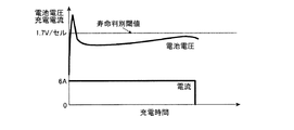
図7は、劣化した電池の充電を行なった場合の電池電圧及び充電電流を示した図である。図7からわかるように、電池が劣化した場合は、充電初期において電池電圧が急激に上昇する。従って、この種の電池は、この急激な電圧上昇値が所定寿命判別閾値以上である場合は寿命であると判別できる。
しかしながら、電池は種類や電池内部の材料、製造方法等によって異なる電圧挙動を示すため、単純に電池電圧が寿命判別閾値以上であるか否かで寿命判別を行うだけでは、判別することが困難である場合がある。 However, since the battery exhibits different voltage behavior depending on the type, the material inside the battery, the manufacturing method, etc., it is difficult to determine simply by determining the life based on whether the battery voltage is equal to or higher than the life determination threshold. There may be.
すなわち、電池の種類によっては、正常な電池、劣化した電池どちらの場合においても、充電初期において急激な電池電圧の上昇が起こらない場合がある。このような特性を示す電池においては、単純に電池電圧が寿命判別閾値以上であるか否かを判別するだけでは寿命判別は行なえない。 That is, depending on the type of battery, in both cases of a normal battery and a deteriorated battery, there is a case where the battery voltage does not rapidly increase at the initial stage of charging. In a battery having such characteristics, the life cannot be determined simply by determining whether or not the battery voltage is equal to or higher than the life determination threshold.
本発明の目的は、上記課題を解決するために、電池の種類に拘わらず電池の寿命を確実に判別できるようにすることである。また、本発明の他の目的は、電池の劣化状態をユーザに簡易に認知させることである。 In order to solve the above-described problems, an object of the present invention is to reliably determine the life of a battery regardless of the type of battery. Another object of the present invention is to allow the user to easily recognize the deterioration state of the battery.
請求項1の電池寿命判別装置は、上記目的を達成するため、電池の電池電圧を検出する電池電圧検出手段と、前記電池電圧検出手段により検出された電池電圧を記憶する電池電圧記憶手段と、前記電池電圧検出手段により検出された電池電圧と所定時間前の電池電圧とから電池電圧勾配を演算する電池電圧勾配演算手段と、前記電池電圧検出手段が充電開始前に検出した電池電圧を所定電圧と比較して電池容量の残存状態を判定する比較手段と、充電開始前の前記電池電圧が前記所定電圧値以下であり、かつ、充電開始後所定時間内の前記電池電圧勾配が第1の所定値以上である場合は、前記電池は寿命であると判別する判別手段と、を備えたことを技術的特徴としている。 In order to achieve the above object, the battery life determination device according to claim 1 is a battery voltage detection means for detecting a battery voltage of a battery, a battery voltage storage means for storing a battery voltage detected by the battery voltage detection means, A battery voltage gradient calculating means for calculating a battery voltage gradient from a battery voltage detected by the battery voltage detecting means and a battery voltage a predetermined time ago; and a battery voltage detected by the battery voltage detecting means before the start of charging. and determining comparing means the residual state of the battery capacity as compared to, and in the battery voltage before the start of charging than the predetermined voltage value, and the battery voltage gradient within the charge start after a predetermined time a first predetermined When the value is equal to or greater than the value, the battery is characterized in that it includes a discriminating unit that discriminates that the battery has a lifetime.
請求項1に記載の電池寿命判別装置によれば、電池電圧勾配の第1の所定値を定め、充電開始前の電池電圧が所定電圧値以下で、充電初期の電池電圧勾配が第1の所定値以上である場合に電池が寿命であると判別され、寿命を判別可能な電池の種類が増加する。 According to the battery life discriminating device of claim 1 , the first predetermined value of the battery voltage gradient is determined, the battery voltage before the start of charging is equal to or lower than the predetermined voltage value, and the battery voltage gradient at the initial stage of charging is the first predetermined value. When the value is equal to or greater than the value, it is determined that the battery has a lifetime, and the types of batteries whose lifetime can be determined increase.
請求項2の電池寿命判別装置は、上記目的を達成するため、請求項1記載の電池寿命判別装置において、前記判別手段は、充電開始後所定時間内の前記電池電圧勾配が前記第1の所定値未満、かつ前記第1の所定値未満の値である第2の所定値以上であり、かつ、充電開始前の前記電池電圧が前記所定電圧値以下である場合は、前記電池は寿命間近であると判別することを技術的特徴としている。
In order to achieve the above object, the battery life discriminating apparatus according to
請求項3の電池寿命判別装置は、上記目的を達成するため、請求項1記載の電池寿命判別装置において、前記判別手段は、充電開始後所定時間内の前記電池電圧勾配が前記第1の所定値未満の値である第2の所定値未満である場合は、前記電池は正常であると判別することを技術的特徴としている。
Battery life discriminating device according to
請求項4の電池寿命判別装置は、上記目的を達成するため、請求項1から3のいずれか一項に記載の電池寿命判別装置において、前記電池の判別結果をユーザに認知させる表示手段を設けたことを技術的特徴としている。即ち、表示手段により、電池が寿命に達していること、電池が寿命間近であること、あるいは電池が正常であることをユーザに認知させることができる。
In order to achieve the above object, the battery life determination apparatus according to
充電装置において電池組の寿命を短時間で確実に判別することができる。また、電池の劣化状態をユーザに簡易に認知させることができる。 In the charging device, the lifetime of the battery set can be reliably determined in a short time. In addition, the user can easily recognize the deterioration state of the battery.
以下、本発明の一実施の形態について添付図面を参照しながら説明する。本実施の形態による電池寿命判別装置は、各種電池の寿命を判別する装置であり、ニカド電池やニッケル水素電池からなる電池パック等の充電装置の付加機能として提供される。 Hereinafter, an embodiment of the present invention will be described with reference to the accompanying drawings. The battery life determination device according to the present embodiment is a device for determining the life of various batteries, and is provided as an additional function of a charging device such as a battery pack made of a nickel-cadmium battery or a nickel-hydrogen battery.
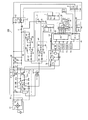
まず、図1を参照しながら充電装置100について説明する。充電装置100は交流電源1に接続することで充電可能になり、1次側整流平滑回路10、スイッチング回路20及び2次側整流平滑回路30からなる電源回路を有し、当該電源回路から供給される電力で電池パック2の充電を行う。
First, the
電池パック2は、複数のセルを直列に接続した電池組2aと、セルに接触又は近接して電池温度を検出する例えばサーミスタ等からなる温度検出素子2bと、セル数に応じて例えば抵抗値が設定されているセル数判別素子2cを内蔵している。
The
1次側整流平滑回路10は全波整流回路11と平滑用コンデンサ12からなり、スイッチング回路20は高周波トランス21、MOSFET22、SW制御IC23、SW制御IC用定電圧回路24、起動抵抗25からなる。高周波トランス21は1次巻線21a、2次巻線21b、3次巻線21c、4次巻線21dを有する。1次巻線21aは入力電圧印加用巻線、2次巻線21bはSW制御IC23用の出力巻線、3次巻線21cは電池パック2を充電するための出力巻線、4次巻線21dは後述するマイクロコンピュータ50(以下、「マイコン50」という。)、充電電流制御回路60等の電源用の出力巻線である。尚1次巻線21aに対し、2次巻線21b、4次巻線21dは同極性の構成であり、3次巻線21cは逆極性である。
The primary side rectifying /
SW制御IC23はMOSFET22の駆動パルス幅を変えて出力電圧を調整するスイッチング電源ICである。また、SW制御IC用定電圧回路24はダイオード24a、3端子レギュレータ24b、コンデンサ24c、24dから構成されており、2次巻線21bからの出力電圧を定電圧化する。2次側整流平滑回路30はダイオード31、平滑用コンデンサ32、抵抗33からなる。
The
充電装置100には、電源回路からの出力を定電流制御するために、電池パック2に流れる充電電流を検出する電流検出回路3と、電流検出回路3とスイッチング回路20との間の帰還路にフォトカプラ5を介して接続された充電電流制御回路60が設けられている。また、電源回路からの出力を定電圧制御するために、出力電圧検出回路4とスイッチング回路20との間の帰還路にフォトカプラ5を介して接続された出力電圧制御回路80が設けられている。
The
電流検出回路3は抵抗よりなり、電池パック2に流れる充電電流を検出し、充電電流制御回路60に入力する。出力電圧検出回路4は抵抗4a、4bからなり、電源回路の2次側整流平滑回路30の出力電圧を抵抗4a、4bで分圧し、出力電圧制御回路80に入力する。フォトカプラ5は2次側整流平滑回路30の出力電圧、及び充電電流の信号をSW制御IC23に帰還する信号伝達手段である。
The
充電電流制御回路60には、基準電流値を設定するための充電電流設定回路7が接続されている。充電電流設定回路7は、抵抗7a、7bからなり、これらの抵抗の分圧比で設定された電圧値が充電電流設定基準電圧として設定される。出力電圧制御回路80には、基準電圧値を設定するための出力電圧設定回路6が接続されている。出力電圧設定回路6は抵抗6a、6bからなり、抵抗6a、6bの分圧比で設定された電圧値が基準電圧になり、2次側整流平滑回路30の出力電圧基準電圧として設定される。
The charging
充電電流制御回路60は、演算増幅器61、62、抵抗63〜67、ダイオード68からなる。充電電流制御回路60は、充電電流検出回路3に流れる充電電流を検出し、この充電電流に対応する電圧を反転増幅させた出力電圧と、充電電流設定回路7で設定された充電電流設定基準電圧との差を増幅し、フォトカプラ5を介してSW制御IC23に帰還をかけ制御する。すなわち、充電電流が大きい場合はパルス幅を狭めたパルスを、逆の場合はパルス幅を広げたパルスを高周波トランス21に与え2次側整流平滑回路30で直流に平滑し、充電電流を一定に保つ。すなわち、電流検出回路3、充電電流制御回路60、充電電流設定回路7、フォトカプラ5、スイッチング回路20、2次側整流平滑回路30を介して充電電流が設定電流値となるように制御する。
The charging
出力電圧制御回路80は演算増幅器81、抵抗82〜85、ダイオード86からなる。出力電圧制御回路80は、出力電圧検出回路4からの電圧と出力電圧設定回路6からの電圧との差を増幅し、フォトカプラ5を介してSW制御IC23に帰還をかけ出力電圧を制御する。すなわち、出力電圧が大きい場合はパルス幅を狭めたパルスを、逆の場合はパルス幅を広げたパルスを高周波トランス21に与え2次側整流平滑回路30で直流に平滑し、出力電圧を一定に保つ。すなわち、出力電圧検出回路4、出力電圧制御回路80、出力電圧設定回路6、フォトカプラ5、スイッチング回路20、2次側整流平滑回路30を介して出力電圧が設定電圧値となるように制御する。
The output
充電装置100は、更に、電池電圧検出回路40、電池温度検出回路8、セル数判別回路9を有している。電池電圧検出回路40は抵抗41、42からなり、電池パック2の端子電圧を分圧して、分圧電圧をマイコン50のA/Dコンバータ55に入力する。
The charging
電池温度検出回路8は抵抗8a、8bからなり、抵抗8aと抵抗8b、及び温度検出素子2bとの分圧比によって決定される分圧電圧がマイコン50のA/Dコンバータ55に入力され、電池温度に応じて温度検出素子2bの抵抗値が変化することで、電池温度に応じた分圧電圧がマイコン50のA/Dコンバータ55に入力される。
The battery
セル数判別回路9は抵抗からなり、電池パック2のセル数に応じて抵抗値が設定されているセル数判別素子2cとの分圧電圧がマイコン50のA/Dコンバータ55に入力される。
The cell
マイコン50は、演算回路(CPU)51、ROM52、RAM53、タイマ54、A/Dコンバータ55、出力ポート(OUT)56、リセット入力ポート(IN)57を有する制御手段である。マイコン50は、A/Dコンバータ55に所定サンプリング時間毎に入力された電池電圧をRAM53に記憶し、CPU51は現在の電池電圧と所定時間前の電池電圧とから電池電圧勾配を演算する。
The
充電装置100には、ダイオード71、コンデンサ72、73、3端子レギュレータ74、リセットIC75からなる定電圧回路70が設けられており、マイコン50、充電電流制御回路60等の電源となる。リセットIC75はマイコン50を初期状態にするためにリセット入力ポート57に対してリセット信号を出力する。
The charging
更に充電装置100には、表示回路90が設けられている。表示回路90は、LED91、92、抵抗93〜96からなる表示手段である。LED91、92は、それぞれ赤色、緑色を発光するLEDで、マイコン50の出力ポート56の出力によって赤色、及び緑色が点灯し、また両方の色を同時に発光させることで、橙色の発光が可能となる。本実施の形態では、LED91は充電開始前、及び充電完了を夫々赤色、及び緑色で表示し、LED92は寿命判別中、及び電池の正常、寿命、寿命間近の3段階表示するLEDであり、正常は橙色、寿命は赤色、寿命間近は緑色の表示をする。
Further, the charging
次に図1の回路図、図2、3の電池電圧及び充電電流の時間依存性の図、図4のフローチャートを参照して充電装置100が実行する電池寿命判別動作を説明する。図4に示すように、電源を投入すると、マイコン50は充電開始前であることを表示すべく、出力ポート56を介してLED91を赤色に点滅させる(ステップ701)。そして、電池パック2の接続待機状態となる(ステップ702)。電池パック2の接続は電池電圧検出回路40、電池温度検出回路8、若しくはセル数判別回路9の信号により判別することができる。
Next, the battery life determination operation performed by the charging
ステップ702において、電池パック2が接続されると、充電を行う前の電池電圧V0をマイコン50のA/Dコンバータ55を介してRAM53に取り込む(ステップ703)。
In step 702, when the
次に、所定の充電電流Iで充電を開始する(ステップ704)。充電電流の制御は、充電開始と同時に電池パック2に流れる充電電流を電流検出回路3により検出し、検出充電電流に対応する電圧と充電電流設定回路7からの充電電流設定基準電圧Vとの差を充電電流制御回路60よりフォトカプラ5を介して、PWM制御IC23に帰還をかけることにより行う。すなわち、充電電流が大きい場合はパルス幅を狭め、逆の場合はパルス幅を広げ、パルス幅に比例したパルスを高周波トランス21に与え2次側整流平滑回路30で直流に平滑し、充電電流を一定に保つ。このように、電流検出回路3、充電電流制御回路60、フォトカプラ5、スイッチング回路20、2次側整流平滑回路30を介して充電電流が所定電流値Iとなるように制御する。
Next, charging is started with a predetermined charging current I (step 704). The charging current is controlled by detecting the charging current flowing in the
充電が開始されると、マイコン50は出力ポート56を介して、LED91を消灯する(ステップ705)。次いで、電池寿命判別中であることを表示すべくLED92を橙色に点滅させる(ステップ706)。
When charging is started, the
次に、マイコン50はサンプリングタイマ54をスタートさせ(ステップ707)、サンプリング時間が経過したら(ステップ708)、サンプリングタイマ54を再スタートさせる(ステップ709)。そして、電池電圧検出回路40において抵抗41、42によって分圧された値を現在の電池電圧Vinとしてマイコン50のA/Dコンバータ55を介して取り込む(ステップ710)。
Next, the
続いて、充電開始から時間t経過した時の電池電圧Vtがマイコン50のRAM53に記憶されているか否かを判別する(ステップ711)。ステップ711において電池電圧Vtが記憶されている場合はステップ714にジャンプする。電池電圧Vtが記憶されていない場合は、充電開始から時間t経過したか否かを判別する(ステップ712)。
Subsequently, it is determined whether or not the battery voltage Vt when the time t has elapsed from the start of charging is stored in the
ステップ712において時間t経過していない場合は、ステップ723において満充電判別を行う。時間t経過している場合は、現在の電池電圧Vinを時間t経過した時の電池電圧Vtとしてマイコン50のRAM53に記憶する(ステップ713)。
If time t has not elapsed in step 712, full charge determination is performed in step 723. If the time t has elapsed, the current battery voltage Vin is stored in the
次に、充電開始から時間T(T>t)経過した時の電池電圧VTがマイコン50のRAM53に記憶されているか否かを判別する(ステップ714)。本実施の形態においては時間Tは1分、時間tは30秒とする。時間T及びtの値は必ずしも上記値である必要はなく適宜定めて良い。ステップ714において、電池電圧VTが記憶されている場合はステップ723において満充電判別を行う。電池電圧VTが記憶されていない場合は、充電開始から時間T経過したか否かを判別する(ステップ715)。
Next, it is determined whether or not the battery voltage VT when the time T (T> t) has elapsed from the start of charging is stored in the
ステップ715において時間T経過していない場合は、ステップ723において満充電判別を行う。時間T経過している場合は、現在の電池電圧Vinを時間T経過した時の電池電圧VTとしてマイコン50のRAM53に記憶する(ステップ716)。
If time T has not elapsed in step 715, full charge determination is performed in step 723. If the time T has elapsed, the current battery voltage Vin is stored in the
次にマイコン50のRAM53に記憶した充電開始前の電池電圧V0が所定値J以上か否かを判別する(ステップ717)。充電開始前の電池電圧V0が所定値Jか否かを判別するのは、電池の容量がある程度残存しているか否かを判別するためである。すなわち、後のステップ718及び719で電池電圧勾配が第1の所定値以上又は第2の所定値以上である場合は、寿命電池又は寿命間近であると判別するが、電池の容量がある程度残存している場合は、充電時の電池電圧勾配は大きくなるので電池電圧勾配が第1の所定値以上又は第2の所定値以上であっても必ずしも寿命電池又は寿命間近であると判別することはできない。よって、ステップ717において、電池の容量がある程度残存しているか否かの判別を行う。
Next, it is determined whether or not the battery voltage V0 before the start of charging stored in the
ステップ717において、充電開始前の電池電圧V0が所定電圧値J以上の場合は、ステップ722にジャンプする。電池電圧V0が所定電圧値J以上でない場合は、マイコン50のCPU51は先にRAM53に記憶した電圧VTから電圧Vtを減算して電池電圧勾配V(T−t)を算出し、その値が電池の寿命判別値である第1の所定値K以上か否かを判別する(ステップ718)。
If the battery voltage V0 before the start of charging is equal to or higher than the predetermined voltage value J in step 717, the process jumps to step 722. When the battery voltage V0 is not equal to or higher than the predetermined voltage value J, the
ここで、ある種の電池が正常な状態と、劣化した状態において充電を行った際の電池電圧及び充電電流の充電時間依存性について説明する。図2は、正常な電池の充電を行なった場合の電池電圧及び充電電流の充電時間依存性を示した図である。また、図3は、図2の電池が劣化した状態で充電を行なった場合の電池電圧及び充電電流を示した図である。図2、図3において横軸は充電時間tc、縦軸は電池電圧Vin及び充電電流Iである。 Here, the charging time dependency of the battery voltage and the charging current when charging is performed in a state where a certain type of battery is normal and deteriorated will be described. FIG. 2 is a diagram showing the charging time dependence of the battery voltage and charging current when a normal battery is charged. FIG. 3 is a diagram showing a battery voltage and a charging current when charging is performed with the battery of FIG. 2 deteriorated. 2 and 3, the horizontal axis represents the charging time tc, and the vertical axis represents the battery voltage Vin and the charging current I.
図2及び図3からわかるように、正常な電池、劣化した電池どちらの場合においても、充電初期において急激な電池電圧の上昇はおこらない。しかし、ある種の電池においては、充電初期において寿命電池では電池温度勾配が高めに出て、正常電池では寿命電池と比較して電池温度勾配が低く出る。よって、第1の所定値Kを定め、第1の所定値Kと電池電圧勾配とを比較することにより電池の寿命を判別する。本実施の形態では第一の所定値Kの値は0.06V/セルとする。尚、第1の所定値Kの値はこれに限定するものではなく適宜定めて良い。 As can be seen from FIG. 2 and FIG. 3, in both the normal battery and the deteriorated battery, the battery voltage does not increase suddenly at the initial stage of charging. However, in a certain type of battery, the battery temperature gradient is higher in the life battery at the initial stage of charging, and the battery temperature gradient is lower in the normal battery than in the life battery. Therefore, the first predetermined value K is determined, and the battery life is determined by comparing the first predetermined value K with the battery voltage gradient. In the present embodiment, the value of the first predetermined value K is 0.06 V / cell. Note that the value of the first predetermined value K is not limited to this, and may be determined as appropriate.
ステップ718において電池電圧勾配V(T−t)が第1の所定値K(=0.06V/セル)以上である場合、すなわち図3のように電池電圧勾配V(T−t)が0.065V/セルの場合には、電池は寿命であると判別し、マイコン50は出力ポート56を介して電池寿命であることを表示すべくLED92を赤色の点灯させる(ステップ720)。
If the battery voltage gradient V (T−t) is greater than or equal to the first predetermined value K (= 0.06 V / cell) in
ステップ718において電池電圧勾配V(T−t)が第1の所定値K未満である場合は、電池の寿命間近の判別値である第2の所定値S(K>S)以上か否かを判別する(ステップ719)。本実施の形態では第2の所定値Sの値は0.05V/セルとする。尚、第2の所定値Sの値はこれに限定するものではなく適宜定めて良い。ステップ719において電池電圧勾配V(T−t)が第2の所定値S以上である場合は電池は寿命間近であると判別し、マイコン50は出力ポート56を介して電池寿命間近であることを表示すべくLED92を緑に点灯させる(ステップ721)。
If the battery voltage gradient V (T−t) is less than the first predetermined value K in
ステップ719において電池電圧勾配V(T−t)が電池寿命間近か否かを判別する第2の所定値S(=0.05V/セル)未満の場合、すなわち図2のように電池電圧勾配V(T−t)が0.04V/セルの場合には、電池は正常と判別し、マイコン50は出力ポート56を介して電池が正常であることを表示すべくLED92を橙色の点灯させる(ステップ722)。その後、ステップ723において満充電か否かの判別を行う。
In step 719, if the battery voltage gradient V (T−t) is less than a second predetermined value S (= 0.05 V / cell) for determining whether or not the battery life is approaching, that is, the battery voltage gradient V as shown in FIG. If (Tt) is 0.04 V / cell, it is determined that the battery is normal, and the
電池パック2が満充電か否かの判別には周知の如く種々の検出方法がある。例えば、−ΔV検出法は電池電圧検出回路40の出力に基づいて充電末期のピーク電圧から所定量降下したことを検出して満充電とする。また2階微分検出法は電池電圧がピークに達する前に充電を停止することにより過充電を低減し、電池のサイクル寿命を向上させることを目的とし、電池電圧の時間による2階微分値が負になるのを検出して満充電とする方法である。更に、ΔT検出法は、電池温度検出回路8の出力に基づいて充電開始からの電池の温度上昇値が所定の温度上昇値以上になるのを検出して満充電とする方法である。
There are various detection methods for determining whether or not the
この他、特開昭62−193518号、特開平2−246739号、実開平3−34638号公報等に記載されているように充電時における所定時間当りの電池温度上昇率(温度勾配)が所定値以上になるのを検出して満充電とするdT/dt検出法等があり、本実施の形態では任意の一つないし複数の満充電検出法を用いて行えばよい。 In addition, as described in JP-A-62-193518, JP-A-2-24639, JP-A-3-34638, etc., the battery temperature increase rate (temperature gradient) per predetermined time during charging is predetermined. There is a dT / dt detection method for detecting full-charge when a value becomes equal to or greater than a value, and any one or a plurality of full-charge detection methods may be used in this embodiment.
ステップ723において満充電と判別された場合は、マイコン50は出力ポート56を介してLED92を消灯し(ステップ724)、充電完了であることを表示すべくLED91を緑色に点灯させる(ステップ725)。その後、電池パック2が充電装置100から抜かれたか否かを判別し(ステップ726)、抜かれた場合はステップ702に戻る。ステップ723において満充電と判別されなかった場合はステップ708に戻る。
If it is determined in step 723 that the battery is fully charged, the
以上詳細に説明したように、本実施の形態による充電装置100においては、充電前に電池パック2の電圧を計測して所定電圧値Jと比較し、充電開始後の所定時間、例えば30秒後から1分後までの電池電圧勾配を計測して第1の所定値K及び第2の所定値Sと比較する。電圧値が所定電圧値J以下でかつ電池電圧勾配が第1の所定値K以上である場合には、電池パック2を寿命であると判定し、LED92を赤に点灯させる。電圧値が所定電圧値J以下でかつ電池電圧勾配が第2の所定値S以上第1の所定値K未満である場合には、電池パック2を寿命間近であると判定し、LED92を緑に点灯させる。また、電圧値が所定電圧値J以下でかつ電池電圧勾配が第2の所定値S未満の場合には、電池パック2は正常であると判定し、LED92を橙に点灯させる。これにより、短時間でかつ確実に電池組の寿命を判別することができると共に、電池の状態を視覚的に認知できるように表示している。
As described above in detail, in charging
尚、本発明の電池寿命判別装置は、上記した実施の形態に限定されるものではなく、本発明の要旨を逸脱しない範囲内において種々変更を加え得ることは勿論である。例えば、本実施の形態では寿命判別の閾値をK=0.06V/セル、寿命間近判別の閾値をS=0.05V/セルとしたが、低温時には電池電圧勾配が高めに出る傾向にあるので、充電開始時の電池温度によって閾値を変えても良い。例えば、電池温度が10℃以下の場合は閾値を1.3倍程度にしてもよい。尚、閾値の具体的数値は上記した例に限られるものではない。 It should be noted that the battery life determination device of the present invention is not limited to the above-described embodiment, and it is needless to say that various changes can be made without departing from the gist of the present invention. For example, in this embodiment, the threshold for determining the life is K = 0.06 V / cell and the threshold for determining the near-life is S = 0.05 V / cell, but the battery voltage gradient tends to increase at low temperatures. The threshold value may be changed depending on the battery temperature at the start of charging. For example, when the battery temperature is 10 ° C. or less, the threshold value may be about 1.3 times. In addition, the specific numerical value of a threshold value is not restricted to the above-mentioned example.
また、電池電圧勾配の第1の所定値Kと同一又は異なる値の所定値(第3の所定値)を設定し、充電前の電池電圧V0が所定電圧値J以下であるか否かに拘わらず、電池電圧勾配が第3の所定値以上である場合を寿命、第2の所定値S以上第3の所定値未満である場合を寿命間近と判定するようにしてもよい。このとき、所定値については、電池の種類や測定環境などによって変更が可能である。 Further, a predetermined value (third predetermined value) that is the same as or different from the first predetermined value K of the battery voltage gradient is set, and whether or not the battery voltage V0 before charging is equal to or lower than the predetermined voltage value J is determined. Instead, it may be determined that the battery voltage gradient is greater than or equal to the third predetermined value, and that the lifetime is near when the battery voltage gradient is greater than or equal to the second predetermined value S and less than the third predetermined value. At this time, the predetermined value can be changed depending on the type of battery, measurement environment, and the like.
本発明による電池寿命判別装置は、例えば電動工具などの電池の寿命判定に用いることができる。 The battery life discriminating apparatus according to the present invention can be used for determining the life of a battery such as an electric tool.
100:電池寿命判別装置(充電装置)、2:電池パック、40:電池電圧検出回路、51:CPU、53:RAM、90:LED
100: Battery life determination device (charging device), 2: Battery pack, 40: Battery voltage detection circuit, 51: CPU, 53: RAM, 90: LED
Claims (4)
前記電池電圧検出手段により検出された電池電圧を記憶する電池電圧記憶手段と、
前記電池電圧検出手段により検出された電池電圧と所定時間前の電池電圧とから電池電圧勾配を演算する電池電圧勾配演算手段と、
前記電池電圧検出手段が充電開始前に検出した電池電圧を所定電圧と比較して電池容量の残存状態を判定する比較手段と、
充電開始前の前記電池電圧が前記所定電圧値以下であり、かつ、充電開始後所定時間内の前記電池電圧勾配が第1の所定値以上である場合は、前記電池は寿命であると判別する判別手段と、を備えたことを特徴とする電池寿命判別装置。 Battery voltage detecting means for detecting the battery voltage of the battery;
Battery voltage storage means for storing the battery voltage detected by the battery voltage detection means;
And the battery voltage gradient computing means for computing a battery voltage gradient from the detected battery voltage and a predetermined time before the battery voltage by the battery voltage detecting means,
Comparing means for comparing the battery voltage detected by the battery voltage detecting means before the start of charging with a predetermined voltage to determine the remaining state of the battery capacity;
The battery voltage before the start of charging is not less than the predetermined voltage value, and, if the battery voltage gradient within the charge start after a predetermined time is not less than the first predetermined value, it is determined that the battery is life battery life determination apparatus characterized by comprising: a discriminating means.
Priority Applications (4)
| Application Number | Priority Date | Filing Date | Title |
|---|---|---|---|
| JP2005203509A JP4952971B2 (en) | 2005-07-12 | 2005-07-12 | Battery life discriminator |
| US11/483,741 US7800343B2 (en) | 2005-07-12 | 2006-07-11 | Battery charger with battery life judging function |
| DE102006032261A DE102006032261A1 (en) | 2005-07-12 | 2006-07-12 | Battery charger with battery life test function |
| CN2006101015531A CN1896762B (en) | 2005-07-12 | 2006-07-12 | Battery charger with battery life judging function |
Applications Claiming Priority (1)
| Application Number | Priority Date | Filing Date | Title |
|---|---|---|---|
| JP2005203509A JP4952971B2 (en) | 2005-07-12 | 2005-07-12 | Battery life discriminator |
Publications (3)
| Publication Number | Publication Date |
|---|---|
| JP2007024541A JP2007024541A (en) | 2007-02-01 |
| JP2007024541A5 JP2007024541A5 (en) | 2008-07-17 |
| JP4952971B2 true JP4952971B2 (en) | 2012-06-13 |
Family
ID=37609317
Family Applications (1)
| Application Number | Title | Priority Date | Filing Date |
|---|---|---|---|
| JP2005203509A Expired - Fee Related JP4952971B2 (en) | 2005-07-12 | 2005-07-12 | Battery life discriminator |
Country Status (4)
| Country | Link |
|---|---|
| US (1) | US7800343B2 (en) |
| JP (1) | JP4952971B2 (en) |
| CN (1) | CN1896762B (en) |
| DE (1) | DE102006032261A1 (en) |
Families Citing this family (22)
| Publication number | Priority date | Publication date | Assignee | Title |
|---|---|---|---|---|
| JP4877181B2 (en) * | 2006-10-23 | 2012-02-15 | ソニー株式会社 | Charging apparatus and charging method |
| US7633266B2 (en) * | 2007-01-05 | 2009-12-15 | Bcd Semiconductor Manufacturing Limited | Charger circuit and transformer used therein |
| JP5015760B2 (en) * | 2007-12-27 | 2012-08-29 | 京セラ株式会社 | Portable electronic devices |
| KR101065974B1 (en) * | 2009-10-30 | 2011-09-19 | 삼성에스디아이 주식회사 | Control Circuit of Secondary Battery |
| TW201215904A (en) * | 2010-10-15 | 2012-04-16 | Lifetech Energy Inc | Monitoring method of lithium battery life status |
| JP5307113B2 (en) * | 2010-12-20 | 2013-10-02 | 古河電気工業株式会社 | Full charge detection device and full charge detection method |
| JP5887531B2 (en) * | 2011-09-09 | 2016-03-16 | パナソニックIpマネジメント株式会社 | Charger |
| JP5879557B2 (en) | 2011-09-12 | 2016-03-08 | パナソニックIpマネジメント株式会社 | Charger |
| CN102638077A (en) * | 2012-04-11 | 2012-08-15 | 常州市林科电器有限公司 | Intelligent display charger |
| CN103066666B (en) * | 2013-01-22 | 2015-08-26 | 矽力杰半导体技术(杭州)有限公司 | A kind of booster type battery charging management system and control method thereof |
| CN103323783B (en) * | 2013-06-20 | 2016-01-13 | 上海华勤通讯技术有限公司 | The appraisal procedure of mobile terminal and battery life |
| US20160193474A1 (en) * | 2013-08-13 | 2016-07-07 | Koninklijke Philips N.V. | Automated battery indication and feedback system based on environmental conditions and use data for improved management and reliability |
| KR102635868B1 (en) * | 2016-01-26 | 2024-02-14 | 삼성전자주식회사 | Electronic device and controlling method thereof |
| US11437829B2 (en) | 2016-03-07 | 2022-09-06 | The Regents Of The University Of Michigan | Method to charge lithium-ion batteries with user, cell and temperature awareness |
| CN105738831B (en) * | 2016-04-22 | 2018-11-27 | 广东小天才科技有限公司 | A kind of the battery capacity monitoring method and device of mobile terminal |
| KR20180074301A (en) | 2016-12-23 | 2018-07-03 | 삼성전자주식회사 | Method and apparatus for determining abnormal state of battery |
| CN106848448A (en) * | 2017-01-12 | 2017-06-13 | 深圳市信宇人科技有限公司 | Lithium-ion-power cell on-line monitoring method and its electrokinetic cell based on wireless transmission method |
| US11258285B2 (en) | 2017-06-06 | 2022-02-22 | The Regents Of The University Of Michigan | User aware charging algorithm that reduces battery fading |
| CN107179512B (en) * | 2017-07-12 | 2020-06-19 | 万帮充电设备有限公司 | Method and device for predicting service life of battery |
| WO2019077711A1 (en) * | 2017-10-18 | 2019-04-25 | 日本たばこ産業株式会社 | Battery unit, flavor inhaler, method for controlling battery unit, and program |
| CN112968481B (en) * | 2019-12-13 | 2023-05-30 | 北京小米移动软件有限公司 | Charging circuit and electronic device |
| WO2021154873A1 (en) * | 2020-01-28 | 2021-08-05 | Fk Irons Inc. | Pen style wireless tattoo machine, system, & kits |
Family Cites Families (12)
| Publication number | Priority date | Publication date | Assignee | Title |
|---|---|---|---|---|
| GB2245781A (en) * | 1990-06-29 | 1992-01-08 | Wu Ko Lee | A device for controlling charging of a battery and displaying charge level |
| US5166623A (en) * | 1991-03-04 | 1992-11-24 | Motorola, Inc. | Method for indicating battery capacity |
| US5677615A (en) * | 1994-02-10 | 1997-10-14 | Hitachi Koki Co., Ltd. | Service-life discriminating feature added to a battery charger |
| JP3336790B2 (en) | 1994-02-10 | 2002-10-21 | 日立工機株式会社 | Battery life judgment device for battery charger |
| JPH0946916A (en) * | 1995-08-02 | 1997-02-14 | Honda Motor Co Ltd | Charging controller |
| US5684404A (en) * | 1995-11-17 | 1997-11-04 | Sharp Microelectronics Technology, Inc. | System and method of measuring a battery lifetime |
| CN1116615C (en) * | 1995-11-29 | 2003-07-30 | 欧姆龙株式会社 | Device and method for estimating remaining life of battery |
| US6222370B1 (en) * | 1998-03-13 | 2001-04-24 | Brian Walter Schousek | Universal battery monitor |
| DE19952693A1 (en) | 1999-10-14 | 2001-05-23 | Akkumulatorenfabrik Moll Gmbh | Measurement, determination and display of condition of an automotive starter battery using one or more sensor for measuring charge, temperature, voltage, etc. to provided detailed information about current and future state, etc. |
| JP2004120856A (en) * | 2002-09-25 | 2004-04-15 | Matsushita Electric Ind Co Ltd | Power supply |
| JP2005039875A (en) * | 2003-07-15 | 2005-02-10 | Matsushita Electric Ind Co Ltd | Method for charging secondary battery and apparatus for charging using the same |
| JP2005110371A (en) * | 2003-09-29 | 2005-04-21 | Casio Comput Co Ltd | Method of annunciating discharge/charge information, image pickup device, and program |
-
2005
- 2005-07-12 JP JP2005203509A patent/JP4952971B2/en not_active Expired - Fee Related
-
2006
- 2006-07-11 US US11/483,741 patent/US7800343B2/en not_active Expired - Fee Related
- 2006-07-12 DE DE102006032261A patent/DE102006032261A1/en not_active Withdrawn
- 2006-07-12 CN CN2006101015531A patent/CN1896762B/en not_active Expired - Fee Related
Also Published As
| Publication number | Publication date |
|---|---|
| JP2007024541A (en) | 2007-02-01 |
| DE102006032261A1 (en) | 2007-04-19 |
| US20070013344A1 (en) | 2007-01-18 |
| CN1896762B (en) | 2010-07-21 |
| US7800343B2 (en) | 2010-09-21 |
| CN1896762A (en) | 2007-01-17 |
Similar Documents
| Publication | Publication Date | Title |
|---|---|---|
| JP4952971B2 (en) | Battery life discriminator | |
| KR101256079B1 (en) | Balancing Method and Balancing System of Battery Pack | |
| US6954051B2 (en) | Battery charger and charging method | |
| EP2690744A2 (en) | Battery charging method and battery pack utilizing the same | |
| JP2008236878A (en) | Charging device | |
| JPH11252814A (en) | Charging apparatus and method | |
| JP2008193797A (en) | Charging device | |
| JP4251158B2 (en) | Charger and electric tool set using the same | |
| WO2014087675A2 (en) | Charging device | |
| JP5418871B2 (en) | Charger | |
| JP4434108B2 (en) | Charger | |
| JP2008187790A (en) | Charger | |
| JP2010016976A (en) | Charging system | |
| JPH11341694A (en) | Charging method of secondary battery | |
| CN102959829A (en) | Secondary battery charging method and charging apparatus | |
| JPH0898417A (en) | Charge/discharge control method for secondary battery | |
| JP3707636B2 (en) | Charge control method and charge control device | |
| JP2002017050A (en) | Charging circuit of secondary battery | |
| JP2015029390A (en) | Charger | |
| JP3722091B2 (en) | Battery assembly life discriminator for charger | |
| JP2005276733A (en) | Charging device | |
| JP4022872B2 (en) | Battery charger | |
| JP4046139B2 (en) | Battery charger | |
| JP4038820B2 (en) | Charger | |
| JP2010016975A (en) | Charging system and battery pack used for the system |
Legal Events
| Date | Code | Title | Description |
|---|---|---|---|
| A521 | Written amendment |
Free format text: JAPANESE INTERMEDIATE CODE: A523 Effective date: 20080529 |
|
| A621 | Written request for application examination |
Free format text: JAPANESE INTERMEDIATE CODE: A621 Effective date: 20080529 |
|
| A977 | Report on retrieval |
Free format text: JAPANESE INTERMEDIATE CODE: A971007 Effective date: 20101227 |
|
| A131 | Notification of reasons for refusal |
Free format text: JAPANESE INTERMEDIATE CODE: A131 Effective date: 20110106 |
|
| A521 | Written amendment |
Free format text: JAPANESE INTERMEDIATE CODE: A523 Effective date: 20110304 |
|
| A131 | Notification of reasons for refusal |
Free format text: JAPANESE INTERMEDIATE CODE: A131 Effective date: 20111208 |
|
| A521 | Written amendment |
Free format text: JAPANESE INTERMEDIATE CODE: A523 Effective date: 20120130 |
|
| TRDD | Decision of grant or rejection written | ||
| A01 | Written decision to grant a patent or to grant a registration (utility model) |
Free format text: JAPANESE INTERMEDIATE CODE: A01 Effective date: 20120216 |
|
| A01 | Written decision to grant a patent or to grant a registration (utility model) |
Free format text: JAPANESE INTERMEDIATE CODE: A01 |
|
| A61 | First payment of annual fees (during grant procedure) |
Free format text: JAPANESE INTERMEDIATE CODE: A61 Effective date: 20120229 |
|
| R150 | Certificate of patent or registration of utility model |
Free format text: JAPANESE INTERMEDIATE CODE: R150 |
|
| FPAY | Renewal fee payment (event date is renewal date of database) |
Free format text: PAYMENT UNTIL: 20150323 Year of fee payment: 3 |
|
| LAPS | Cancellation because of no payment of annual fees |