JP4944992B2 - Apparatus and method for feeding flat material pieces and conveying the flat material pieces in a correct manner - Google Patents
Apparatus and method for feeding flat material pieces and conveying the flat material pieces in a correct manner Download PDFInfo
- Publication number
- JP4944992B2 JP4944992B2 JP2010518524A JP2010518524A JP4944992B2 JP 4944992 B2 JP4944992 B2 JP 4944992B2 JP 2010518524 A JP2010518524 A JP 2010518524A JP 2010518524 A JP2010518524 A JP 2010518524A JP 4944992 B2 JP4944992 B2 JP 4944992B2
- Authority
- JP
- Japan
- Prior art keywords
- flat material
- suction
- roller
- material piece
- gripper
- Prior art date
- Legal status (The legal status is an assumption and is not a legal conclusion. Google has not performed a legal analysis and makes no representation as to the accuracy of the status listed.)
- Expired - Fee Related
Links
Images


Classifications
-
- B—PERFORMING OPERATIONS; TRANSPORTING
- B65—CONVEYING; PACKING; STORING; HANDLING THIN OR FILAMENTARY MATERIAL
- B65H—HANDLING THIN OR FILAMENTARY MATERIAL, e.g. SHEETS, WEBS, CABLES
- B65H11/00—Feed tables
- B65H11/002—Feed tables incorporating transport belts
- B65H11/005—Suction belts
-
- B—PERFORMING OPERATIONS; TRANSPORTING
- B65—CONVEYING; PACKING; STORING; HANDLING THIN OR FILAMENTARY MATERIAL
- B65H—HANDLING THIN OR FILAMENTARY MATERIAL, e.g. SHEETS, WEBS, CABLES
- B65H5/00—Feeding articles separated from piles; Feeding articles to machines
- B65H5/08—Feeding articles separated from piles; Feeding articles to machines by grippers, e.g. suction grippers
- B65H5/10—Reciprocating or oscillating grippers, e.g. suction or gripper tables
-
- B—PERFORMING OPERATIONS; TRANSPORTING
- B65—CONVEYING; PACKING; STORING; HANDLING THIN OR FILAMENTARY MATERIAL
- B65H—HANDLING THIN OR FILAMENTARY MATERIAL, e.g. SHEETS, WEBS, CABLES
- B65H5/00—Feeding articles separated from piles; Feeding articles to machines
- B65H5/08—Feeding articles separated from piles; Feeding articles to machines by grippers, e.g. suction grippers
- B65H5/12—Revolving grippers, e.g. mounted on arms, frames or cylinders
-
- B—PERFORMING OPERATIONS; TRANSPORTING
- B65—CONVEYING; PACKING; STORING; HANDLING THIN OR FILAMENTARY MATERIAL
- B65H—HANDLING THIN OR FILAMENTARY MATERIAL, e.g. SHEETS, WEBS, CABLES
- B65H2301/00—Handling processes for sheets or webs
- B65H2301/40—Type of handling process
- B65H2301/44—Moving, forwarding, guiding material
- B65H2301/447—Moving, forwarding, guiding material transferring material between transport devices
- B65H2301/4471—Grippers, e.g. moved in paths enclosing an area
- B65H2301/44714—Grippers, e.g. moved in paths enclosing an area carried by rotating members
-
- B—PERFORMING OPERATIONS; TRANSPORTING
- B65—CONVEYING; PACKING; STORING; HANDLING THIN OR FILAMENTARY MATERIAL
- B65H—HANDLING THIN OR FILAMENTARY MATERIAL, e.g. SHEETS, WEBS, CABLES
- B65H2301/00—Handling processes for sheets or webs
- B65H2301/40—Type of handling process
- B65H2301/44—Moving, forwarding, guiding material
- B65H2301/447—Moving, forwarding, guiding material transferring material between transport devices
- B65H2301/4471—Grippers, e.g. moved in paths enclosing an area
- B65H2301/44716—Grippers, e.g. moved in paths enclosing an area oscillated in arcuate paths
-
- B—PERFORMING OPERATIONS; TRANSPORTING
- B65—CONVEYING; PACKING; STORING; HANDLING THIN OR FILAMENTARY MATERIAL
- B65H—HANDLING THIN OR FILAMENTARY MATERIAL, e.g. SHEETS, WEBS, CABLES
- B65H2301/00—Handling processes for sheets or webs
- B65H2301/40—Type of handling process
- B65H2301/44—Moving, forwarding, guiding material
- B65H2301/447—Moving, forwarding, guiding material transferring material between transport devices
- B65H2301/4472—Suction grippers, e.g. moved in paths enclosing an area
-
- B—PERFORMING OPERATIONS; TRANSPORTING
- B65—CONVEYING; PACKING; STORING; HANDLING THIN OR FILAMENTARY MATERIAL
- B65H—HANDLING THIN OR FILAMENTARY MATERIAL, e.g. SHEETS, WEBS, CABLES
- B65H2301/00—Handling processes for sheets or webs
- B65H2301/40—Type of handling process
- B65H2301/44—Moving, forwarding, guiding material
- B65H2301/447—Moving, forwarding, guiding material transferring material between transport devices
- B65H2301/4473—Belts, endless moving elements on which the material is in surface contact
- B65H2301/44735—Belts, endless moving elements on which the material is in surface contact suction belt
-
- B—PERFORMING OPERATIONS; TRANSPORTING
- B65—CONVEYING; PACKING; STORING; HANDLING THIN OR FILAMENTARY MATERIAL
- B65H—HANDLING THIN OR FILAMENTARY MATERIAL, e.g. SHEETS, WEBS, CABLES
- B65H2801/00—Application field
- B65H2801/42—Die-cutting
-
- Y—GENERAL TAGGING OF NEW TECHNOLOGICAL DEVELOPMENTS; GENERAL TAGGING OF CROSS-SECTIONAL TECHNOLOGIES SPANNING OVER SEVERAL SECTIONS OF THE IPC; TECHNICAL SUBJECTS COVERED BY FORMER USPC CROSS-REFERENCE ART COLLECTIONS [XRACs] AND DIGESTS
- Y10—TECHNICAL SUBJECTS COVERED BY FORMER USPC
- Y10S—TECHNICAL SUBJECTS COVERED BY FORMER USPC CROSS-REFERENCE ART COLLECTIONS [XRACs] AND DIGESTS
- Y10S271/00—Sheet feeding or delivering
- Y10S271/90—Stripper
Landscapes
- Engineering & Computer Science (AREA)
- Mechanical Engineering (AREA)
- Feeding Of Articles By Means Other Than Belts Or Rollers (AREA)
- Delivering By Means Of Belts And Rollers (AREA)
- Sheets, Magazines, And Separation Thereof (AREA)
Description
1.利用分野
本発明は、フラット材料片を加工するための回転機械の作業ステーションにフラット材料片を供給し、かつフラット材料片を見当正しく搬送するための装置及び方法に関する。フラット材料片は、特に板紙あるいはボール紙からなるフラット材料シートであり、回転機械は、特に前述のフラット材料シートから、後に折畳み箱、例えば薬剤用折畳み箱を生産するための折畳み箱裁断片を製造する回転式打抜き機である。しかし、フラット材料片は、別種のシート又は封筒裁断片等であってもかまわない。
1. Field of the Invention The present invention relates to an apparatus and a method for supplying flat material pieces to a rotating machine work station for processing flat material pieces and for conveying the flat material pieces in a correct manner. The flat material piece is a flat material sheet made of paperboard or cardboard in particular, and the rotating machine produces a folding box piece for later production of a folding box, for example a pharmaceutical folding box, especially from the aforementioned flat material sheet. It is a rotary punching machine. However, the flat material piece may be a different type of sheet or envelope piece.
2.技術背景
シート印刷機において、印刷したいシートを、ずれ重なり状態のシートからなる流れの中から引き抜くことは公知である。このために、スインググリッパが、引き抜きたいシートの前縁を把持し、シートを回転式あるいは輪転式のシート印刷機のクロック速度に加速させる。周囲に配置される単数又は複数のローラグリッパを備えるシート受取りローラは、ローラグリッパにより、加速されたシートをスインググリッパから受け取る。シート受取りローラは、受け取ったシートを所定の角度範囲にわたって搬送し、最終的に見当正しく、かつクロック速度で、回転する圧胴の単数又は複数のグリッパに受け渡す。
2. Technical Background It is well known in a sheet printing machine to pull out a sheet to be printed out of a stream of sheets that are out of alignment. For this purpose, the swing gripper grips the leading edge of the sheet to be pulled out and accelerates the sheet to the clock speed of a rotary or rotary sheet printer. A sheet receiving roller including one or a plurality of roller grippers disposed around receives an accelerated sheet from the swing gripper by the roller gripper. The sheet receiving roller conveys the received sheet over a predetermined angular range and finally delivers it to the rotating impression cylinder or grippers at the correct and clock speed.
例えば板紙あるいはボール紙からなるシートから、折畳み箱裁断片を回転式に製造する枠内において、紙シートに比して比較的高い曲げ剛さのために、シートを、少なくとも回転式の機械の、見当合わせ精度が問題となる領域において、可及的真っ直ぐにサクションベルト上を搬送することが有利である。サクションベルト上へのシートの見当正しい供給の形態についての提案は、背景技術からこれまで未知である。 For example, because of the relatively high bending stiffness compared to a paper sheet in a frame in which a folded box piece is produced from a sheet of paperboard or cardboard, the sheet is at least of a rotary machine, In areas where registration accuracy is an issue, it is advantageous to transport the suction belt as straight as possible. Proposals for the form of the correct supply of sheets on the suction belt are unknown to date from the background art.
3.発明の開示
a)技術的課題
それゆえ本発明の課題は、フラット材料片、特にシートを、回転機械の、フラット材料片を搬送するサクションベルトへの見当正しい供給を可能にする、フラット材料片を加工するための回転機械の作業ステーションにフラット材料片を供給し、かつフラット材料片を見当正しく搬送するための装置及び方法を提供することである。
3. DISCLOSURE OF THE INVENTION a) Technical Problem Therefore, the object of the present invention is to provide a flat material piece, in particular a sheet, which enables the correct supply of rotating machines to a suction belt carrying the flat material piece. It is to provide an apparatus and method for feeding flat material pieces to a rotating machine work station for processing and for conveying the flat material pieces in a correct manner.
b)課題の解決
上記課題は、請求項1に記載の特徴を有する装置、要するに、フラット材料片を加工するための機械の作業ステーションにフラット材料片を供給し、かつフラット材料片を見当正しく搬送するための装置であって、‐該フラット材料片の前縁を把持して、該フラット材料片を加速するためのグリッパ装置と、‐加速された前記フラット材料片を前記グリッパ装置から受け取るための少なくとも1つのシート受取りローラとを備え、該シート受取りローラが、該シート受取りローラの周囲で働く、加速された前記フラット材料片を把持するための少なくとも1つのローラグリッパを備え、該ローラグリッパが、前記フラット材料片を保持する閉鎖位置と、前記フラット材料片を解放する開放位置との間で可動である形式のものにおいて、‐前記シート受取りローラが、該シート受取りローラの周囲の、回転方向で見て前記ローラグリッパの後に接続する部分に、サクションエアにより負荷可能な複数のサクション穴を備え、かつ‐サクションエアにより負荷可能な少なくとも1つのサクションベルトを備えるサクションベルト搬送装置が設けられており、‐前記閉鎖位置から前記開放位置への前記ローラグリッパの移行及び前記サクション穴のサクションエア負荷は、前記フラット材料片が実質的にスリップなしに前記シート受取りローラから前記サクションベルトに受渡し可能であるように制御可能であることを特徴とする、フラット材料片を加工するための機械の作業ステーションにフラット材料片を供給し、かつフラット材料片を見当正しく搬送するための装置により解決される。本発明の別の形態は、従属請求項に係る発明である。好ましくは、前記サクションベルトが、前記ローラグリッパの数に対応した数の侵入切欠きを有しており、該侵入切欠き内に、それぞれのローラグリッパが、前記フラット材料片を前記サクションベルトに受け渡す際に侵入する。好ましくは、前記サクションベルト搬送装置が、平行に相並んで延びる、中間スペースを置いて配置される複数のサクションベルトを有しており、前記ローラグリッパが、前記フラット材料片を前記サクションベルトに受け渡す際に前記中間スペース内に侵入する。好ましくは、前記サクションベルト搬送装置が、前記サクションベルトを変向するための変向ローラを有しており、該変向ローラの軸線が前記シート受取りローラの軸線の下に実質的に鉛直に配置されている。好ましくは、前記サクション穴が、前記シート受取りローラの周囲において、90゜より小さな角度範囲にわたって延在する。さらに上記課題は、請求項6に記載の特徴を有する方法、要するに、フラット材料片を加工するための機械の作業ステーションにフラット材料片を供給し、かつフラット材料片を見当正しく搬送するための方法であって、以下のステップ、すなわち:‐グリッパ装置により前記フラット材料片の前縁を把持して、該フラット材料片を加速させ、かつ‐加速された前記フラット材料片を少なくとも1つの回転するシート受取りローラにより前記グリッパ装置から受け取り、加速された前記フラット材料片を、前記シート受取りローラの周囲で働く、前記フラット材料片を保持する閉鎖位置と、前記フラット材料片を解放する開放位置との間で可動な少なくとも1つのローラグリッパにより把持するというステップを有する、フラット材料片を加工するための機械の作業ステーションにフラット材料片を供給し、かつフラット材料片を見当正しく搬送するための方法において、‐前記フラット材料片を前記ローラグリッパに対して付加的に、前記シート受取りローラの周囲の、回転方向で見て前記ローラグリッパの後に接続する部分にあるサクション穴により吸引されるサクションエアによって、前記シート受取りローラの周囲に保持し、‐前記フラット材料片を前記シート受取りローラから、サクションベルト搬送装置の、サクションエアにより負荷される少なくとも1つのサクションベルトに、前記ローラグリッパが前記閉鎖位置から前記開放位置へと運動し、かつ前記サクション穴が、前記ローラグリッパの直近に位置するサクション穴を始点に前記シート受取りローラの回転方向とは逆向きに順番に、少なくともサクションエアのない状態に切り換えられることによって受け渡して、前記フラット材料片を、前記シート受取りローラと前記サクションベルトとの間の受渡しプロセス中、面積が増加する領域において実質的にスリップなしに前記サクションベルトに保持し、かつ面積が減少するものの、なお前記シート受取りローラに維持される領域において追従搬送することを特徴とする、フラット材料片を加工するための機械の作業ステーションにフラット材料片を供給し、かつフラット材料片を見当正しく搬送するための方法により解決される。本発明の別の形態は、従属請求項に係る発明である。好ましくは、前記フラット材料片の前縁の運動方向が、前記サクションベルトにより形成される搬送平面内にあるとき、前記ローラグリッパをその開放位置に動かす。好ましくは、前記フラット材料片の、前記ローラグリッパにより保持される前縁が、前記サクションベルトの吸引作用のないゾーンを越えて搬送されて初めて、前記ローラグリッパをその開放位置へ動かす。好ましくは、前記フラット材料片の前縁を、前記吸引作用のないゾーンを越えての搬送中、前記サクションベルトの搬送平面から外れるように動かす。好ましくは、前記サクション穴を、前記シート受取りローラの軸線に対して平行に配置されるサクション穴列の形態で配置し、該サクション穴列を、前記グリッパ装置から前記フラット材料片を受け取るために個別的に順番にサクションエアで負荷する、かつ/又は前記フラット材料片を前記サクションベルトに受け渡すために個別的に順番に少なくともサクションエアのない状態に切り換える。好ましくは、前記サクション穴を、前記シート受取りローラの軸線に対して平行に配置されるサクション穴列の形態で配置し、該サクション穴列の2つ又は複数の隣接するサクション穴列がそれぞれ1つのサクション穴群を形成するようにし、該サクション穴群を、前記グリッパ装置から前記フラット材料片を受け取るために個別的に順番にサクションエアで負荷する、かつ/又は前記フラット材料片を前記サクションベルトに受け渡すために個別的に順番に少なくともサクションエアのない状態に切り換える。好ましくは、前記ローラグリッパを、前記フラット材料片を前記サクションベルトに受け渡す際に、前記サクションベルトに設けられている侵入切欠き内に侵入させる。好ましくは、前記サクションベルト搬送装置が、平行に相並んで延びる、中間スペースを置いて配置される複数のサクションベルトを有しており、前記ローラグリッパを、フラット材料片を前記サクションベルトに受け渡す際に、前記中間スペース内に侵入させる。
b) Solution of the problem The above object is to supply a flat material piece to a work station of a machine for processing a flat material piece, in short, and to convey the flat material piece in a correct manner. A gripper device for gripping the leading edge of the flat material piece and accelerating the flat material piece; and for receiving the accelerated flat material piece from the gripper device. At least one sheet receiving roller, the sheet receiving roller comprising at least one roller gripper for gripping the accelerated piece of flat material acting around the sheet receiving roller, the roller gripper comprising: In a type that is movable between a closed position for holding the flat material piece and an open position for releasing the flat material piece. The sheet receiving roller has a plurality of suction holes that can be loaded with suction air in a portion around the sheet receiving roller that is connected after the roller gripper when viewed in the rotation direction; and A suction belt conveying device comprising at least one suction belt that can be loaded by: a transition of the roller gripper from the closed position to the open position and a suction air load in the suction hole are the flat piece of material Feeding the flat material piece to the work station of the machine for processing the flat material piece, characterized in that it can be controlled from the sheet receiving roller to the suction belt without slippage And a device for correctly conveying a flat piece of material It is more resolved. Another aspect of the present invention is an invention according to the dependent claims. Preferably, the suction belt has a number of entry notches corresponding to the number of the roller grippers, and each of the roller grippers receives the flat material piece on the suction belt in the entry notches. Invade when handing over. Preferably, the suction belt conveyance device has a plurality of suction belts arranged in parallel with each other and extending in parallel, and the roller gripper receives the flat material piece on the suction belt. When passing, it enters the intermediate space. Preferably, the suction belt conveying device has a direction changing roller for changing the direction of the suction belt, and the axis of the direction changing roller is arranged substantially vertically below the axis of the sheet receiving roller. Has been. Preferably, the suction hole extends over an angular range of less than 90 ° around the sheet receiving roller. Furthermore, the object is to provide a method having the features of
本発明では、シート受取りローラの周囲あるいは外套面の、回転方向で見て少なくとも1つのローラグリッパの後に接続する部分に、サクションエアにより負荷可能な複数のサクション穴を設けることが提案される。このサクション穴により、フラット材料片は、ローラグリッパに対して付加的に、少なくとも部分的に、シート受取りローラの周囲に保持される。サクションベルト搬送装置は、サクションエアにより負荷可能な少なくとも1つのサクションベルトを有しており、このサクションベルトに、フラット材料片がシート受取りローラから本発明において受け渡される。その際、ローラグリッパの開放、ひいては受け渡したいフラット材料片の前縁の解放、及びシート受取りローラに設けられたサクション穴のサクションエア負荷は、フラット材料片が実質的にスリップなしにシート受取りローラからサクションベルトに受渡し可能であるように制御可能である。 In the present invention, it is proposed that a plurality of suction holes that can be loaded with suction air are provided in a portion of the periphery of the sheet receiving roller or the outer surface thereof that is connected after at least one roller gripper when viewed in the rotational direction. With this suction hole, the flat piece of material is held at least partly around the sheet receiving roller in addition to the roller gripper. The suction belt conveyance device has at least one suction belt that can be loaded with suction air, and a flat material piece is delivered to the suction belt from the sheet receiving roller in the present invention. At that time, the opening of the roller gripper, and hence the release of the leading edge of the flat material piece to be delivered, and the suction air load of the suction hole provided in the sheet receiving roller are caused by the flat material piece from the sheet receiving roller substantially without slipping. It can be controlled so that it can be delivered to the suction belt.
ローラグリッパに対して付加的にシート受取りローラに配置されたサクション穴は、有利にはフラット材料片の厚さが変動してもフラット材料片の確実な搬送を保証する。このことは、グリッパが常にフラット材料片の所定の厚さに合わせて調整されなければならないことから生じる。それゆえ、所定の厚さを下回る比較的薄いフラット材料片は、グリッパにより不十分な強さで、ひいては滑りが回避されていない状態で保持される場合がある。この場合、サクション穴を通して吸い込まれたサクションエアは、比較的薄いフラット材料片も、グリッパの作用が減じられているにもかかわらず、安定に、かつ滑り止めされてシート受取りローラに保持することを可能にする。これにより、本発明の枠内で、フラット材料片の厚さに関してより大きな公差が許容可能である。 Suction holes arranged in the sheet receiving roller in addition to the roller gripper advantageously ensure a reliable transport of the flat material piece even if the thickness of the flat material piece varies. This arises from the fact that the gripper must always be adjusted to the predetermined thickness of the flat material piece. Therefore, relatively thin pieces of flat material that are less than a predetermined thickness may be held with insufficient strength by the gripper and thus slipping is not avoided. In this case, the suction air sucked in through the suction hole can keep the relatively thin flat piece of material stably and non-sliply held by the sheet receiving roller even though the action of the gripper is reduced. enable. This allows a greater tolerance for the thickness of the flat material piece within the framework of the invention.
サクションベルトが常時サクションエアにより負荷される一方で、シート受取りローラに設けられたサクション穴のサクションエア負荷は、一方ではグリッパ装置からシート受取りローラによりフラット材料片を受け取るために、他方ではシート受取りローラからサクションベルトにフラット材料片を受け渡すために制御可能である。 While the suction belt is constantly loaded with suction air, the suction air load in the suction hole provided in the sheet receiving roller receives a flat material piece from the gripper device on the one hand by the sheet receiving roller, and on the other hand the sheet receiving roller Can be controlled to deliver a flat piece of material to the suction belt.
シート受取りローラからサクションベルトにフラット材料片を受け渡す際、ローラグリッパの開放と同時に又は直後に、サクション穴が、周方向でローラグリッパの直近に位置するサクション穴を始点にシート受取りローラの回転方向とは逆向きに、時間的に順番に、少なくともサクションエアのない状態に切り換えられる。その際、フラット材料片は、大きさあるいは面積が増加する領域において実質的にスリップフリーにサクションベルトに保持され、かつ大きさあるいは面積が減少するものの、なおシート受取りローラに維持される領域において追従搬送される。 When the flat material piece is transferred from the sheet receiving roller to the suction belt, the rotation direction of the sheet receiving roller starts from the suction hole positioned immediately adjacent to the roller gripper in the circumferential direction immediately after or immediately after the roller gripper is opened. Contrary to the above, at least the suction air is switched in time order. At that time, the flat material piece is held in the suction belt substantially slip-free in the area where the size or area increases, and follows the area where the size or area decreases but is still maintained by the sheet receiving roller. Be transported.
サクション穴のサクションエア切断は、自体公知の形式で、シート受取りローラの一方の端面に配置される制御弁により実施される。本発明の枠内で、単に、サクション穴のサクションエア負荷を遮断するだけでなく、サクション穴を付加的にシート受取りローラの回転方向とは逆向きに順番に圧縮空気で負荷して、シート受取りローラの外套面からのフラット材料片の剥離プロセスを助成することも可能である。この最適な手段は、本願で使用される表現「少なくともサクションエアのない状態に」に包含されるべきである。 The suction air cutting of the suction holes is performed by a control valve arranged on one end face of the sheet receiving roller in a manner known per se. Within the frame of the present invention, not only the suction air load of the suction hole is cut off, but also the suction hole is additionally loaded with compressed air in the direction opposite to the rotation direction of the sheet receiving roller to receive the sheet. It is also possible to aid in the process of peeling the flat material pieces from the outer surface of the roller. This optimal means should be included in the expression “at least in the absence of suction air” as used herein.
有利には、サクション穴は、自体公知の形式で、それぞれ多数のサクション穴を有する、シート受取りローラの軸線に対して平行に配置されるサクション穴列の形態で形成される。シート受取りローラの回転方向とは逆向きにサクションエア負荷を漸次遮断することは、本発明において列毎に実施可能である。その結果、サクション穴列は、順繰りにサクションエアのない状態に切り換えられる。択一的には、周方向で隣接する2つ又は複数のサクション穴列をそれぞれ1つのサクション穴群に統合し、これにより生じたサクション穴群を個別的に順番に少なくともサクションエアのない状態に切り換えてもよい。 Advantageously, the suction holes are formed in a manner known per se in the form of a row of suction holes arranged parallel to the axis of the sheet receiving roller, each having a number of suction holes. In the present invention, the suction air load can be gradually cut off in each row in the direction opposite to the rotation direction of the sheet receiving roller. As a result, the suction hole array is sequentially switched to a state without suction air. Alternatively, two or more adjacent suction hole arrays in the circumferential direction are integrated into one suction hole group, and the resulting suction hole groups are individually and sequentially free of at least suction air. It may be switched.
サクション穴のサクションエア負荷の制御は、グリッパ装置からシート受取りローラによりフラット材料片を受け取る際に、サクション穴が、周方向でローラグリッパの直近に位置するサクション穴を始点にシート受取りローラの回転方向とは逆向きに時間的に順番に、サクションエアのない状態から、サクションエアにより負荷された状態に切り換えられるように実施される。この場合も、列毎の制御に対して択一的に、周方向で隣接する2つ又は複数のサクション穴列を、それぞれ1つのサクション穴群に統合し、これにより生じたサクション穴群を個別的に順番に、サクションエアのない状態から、サクションエアにより負荷された状態に切り換えてもよい。 The suction air load of the suction hole is controlled when the flat material piece is received by the sheet receiving roller from the gripper device, and the rotation direction of the sheet receiving roller starts from the suction hole located in the circumferential direction in the immediate vicinity of the roller gripper. In reverse, the operation is performed so that the state is switched from the state without the suction air to the state loaded with the suction air in time order. Also in this case, as an alternative to the control for each row, two or more suction hole rows adjacent in the circumferential direction are integrated into one suction hole group, and the resulting suction hole group is individually set. Therefore, in order, it may be switched from a state without suction air to a state loaded with suction air.
シート受取りローラの軸線は、有利には、無端循環するサクションベルトを変向するための変向ローラの軸線の上に実質的に鉛直に配置される。このような配置では、場合によっては、サクションベルトの、フラット材料片を受け取るべき領域に、吸引作用のないゾーンが生じることは避けられない。そのような場合、ローラグリッパは、必要とあれば、受け渡したいフラット材料片の、ローラグリッパにより保持された前縁が、シート受取りローラによって吸引作用のないゾーンを越えて搬送されて初めて開放され得る。 The axis of the sheet receiving roller is advantageously arranged substantially vertically above the axis of the turning roller for turning the endless circulating suction belt. In such an arrangement, in some cases, it is inevitable that a zone with no suction action will occur in the region of the suction belt where it should receive the flat piece of material. In such a case, if necessary, the roller gripper can be opened only when the leading edge of the flat material piece to be delivered is conveyed by the sheet receiving roller beyond the non-suction zone by the sheet receiving roller. .
シート受取りローラの軸線を水平方向で、受け渡したいフラット材料片の前縁がサクションベルトの搬送平面に対して接線方向でその吸引ゾーン内を可動であるように、変向ローラの軸線に対してずらして配置することも可能である。このような水平ずれが不可能である場合、フラット材料片の前縁は、ローラグリッパが閉鎖されているとき、吸引作用のないゾーンを越えて搬送され、その際、僅かにサクションベルトの搬送平面から外れて運動されるか、あるいはこの搬送平面から持ち上げられるか、又は浮上されてもよい。こうして、サクションベルトの吸引作用のないゾーンの橋渡しをする、形状結合式に保証された搬送が、必要とあれば達成可能である。 Shift the axis of the direction roller so that the axis of the sheet receiving roller is movable in the suction zone in the horizontal direction and the leading edge of the flat material piece to be transferred is tangential to the conveying plane of the suction belt. It is also possible to arrange them. If such horizontal misalignment is not possible, the leading edge of the flat piece of material is conveyed over a zone without suction when the roller gripper is closed, with a slight conveyance plane of the suction belt. It may be moved out of the way, lifted from this transfer plane or lifted. In this way, it is possible, if necessary, to achieve a form-coupled transport that bridges zones without suction of the suction belt.
単数又は複数のローラグリッパは、半径方向でシート受取りローラの外套面から突出する。サクションベルトの搬送平面が、シート受取りローラの、サクション穴が設けられた外套面領域の運動軌道に対して接線方向で位置することができるように、サクションベルトは、ローラグリッパの数に相当する数の侵入切欠きを有する。侵入切欠きには、それぞれのローラグリッパが、フラット材料片をサクションベルトに受け渡す際に侵入可能である。侵入切欠きは、貫通穴であってもよいし、場合によっては、単にサクションベルトに設けられた凹設部であってもよい。択一的には、サクションベルト搬送装置に、平行に相並んで延びる、中間スペースを置いて配置される複数のサクションベルトあるいは吸引帯を設けてもよい。この場合、単数又は複数のローラグリッパは、フラット材料片をサクションベルトあるいは吸引帯に受け渡す際に、それぞれ1つの中間スペースに侵入可能である。 The one or more roller grippers protrude from the outer surface of the sheet receiving roller in the radial direction. The suction belt has a number corresponding to the number of roller grippers so that the conveyance plane of the suction belt can be positioned tangential to the movement trajectory of the outer surface area of the sheet receiving roller where the suction holes are provided. Has an intrusion notch. Each roller gripper can enter the intrusion notch when delivering the flat piece of material to the suction belt. The intrusion notch may be a through hole or, depending on the case, may simply be a recessed portion provided in the suction belt. Alternatively, the suction belt conveying device may be provided with a plurality of suction belts or suction bands that are arranged side by side and extend in parallel. In this case, the single or plural roller grippers can enter each intermediate space when the flat material piece is transferred to the suction belt or the suction belt.
c)実施の形態
以下に、本発明の一実施の形態について例示的に、添付の図面を参照しながら説明する。
c) Embodiment Hereinafter, an embodiment of the present invention will be described by way of example with reference to the accompanying drawings.
図1には、板紙(Kartonage)あるいはボール紙(Pappe)等からなるフラット材料シートの形態のフラット材料片から折畳み箱裁断片を製造するための回転式打抜き機のフィード部として働く、本発明に係る装置1の一実施の形態が示されている。フラット材料シートBの各々から、複数の、図示しない折畳み箱裁断片が製造される。 FIG. 1 shows the present invention, which functions as a feed part of a rotary punching machine for producing a folded box piece from a flat material piece in the form of a flat material sheet made of paperboard or cardboard. An embodiment of such a device 1 is shown. From each of the flat material sheets B, a plurality of unfolded folding box pieces are produced.
図1には、その他の部分は図示しない自体公知のずれ重なり式ストリームフィーダ(Schuppenstromanleger)の、右から左に傾斜した無端循環式のずれ重なり式ストリームフィードベルト14が示されている。ずれ重なり式ストリームフィードベルト14上には、フラット材料シートBからなるずれ重なり状態の流れが形成される。本実施の形態ではスインググリッパ(Schwinggreifer)として形成されるグリッパ装置2が、双方向矢印で示すように、所定の旋回領域で往復可動に支承されている。グリッパ装置2は、自体公知の形式で、ずれ重なり式ストリームフィードベルト14の、図1で見て左側の端部に接近するように旋回可能であり、その揺動運動の所属の死点において、ずれ重なり式ストリームフィードベルト14上の最も下側のフラット材料シートBの前縁を把持可能である。続いて、グリッパ装置2は、反時計回りに揺動し、フラット材料シートBを回転式打抜き機のクロック速度(Taktgeschwindigkeit)に加速する。クロック速度に加速されたフラット材料シートBは、グリッパ装置2の、図1に示した揺動位置で、シート受取りローラ3に受け渡される。シート受取りローラ3は、クロック速度で回転方向Rに、本実施の形態では時計回りに回転し、特にクロックローラ(Taktwalze)として形成されている。
FIG. 1 shows an endless circulation type offset overlap type
シート受取りローラ3は、その周囲に、図1で見て相前後して位置する2つのローラグリッパ4を有する。ローラグリッパ4は開閉可能である。ローラグリッパ4は、閉鎖位置でフラット材料シートBの前縁を保持し、開放位置でフラット材料シートBの前縁を再び解放する。回転方向Rで見てローラグリッパ4の後方には、サクション穴5が均等に分配配置されている。サクション穴5は、シート受取りローラ3の周囲の約80°の角度範囲にわたって延在する。サクション穴5は、シート受取りローラ3の軸線11に対して平行に延びるサクション穴列内に配置されている。
The
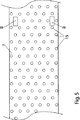
ローラグリッパ4及びサクション穴5により、シート受取りローラ3は、フラット材料シートBを、図1に示したサクションベルト搬送装置6に受け渡す。サクションベルト搬送装置6は、回転式打抜き機のクロック速度で無端循環するように矢印方向に駆動されるサクションベルト7を有する。サクションベルト7の例は、図5に示すようなものである。図5に示すように、サクションベルト7は、パーフォレーション穴15を有する。パーフォレーション穴15を通して、図1に示したサクションボックス16により周囲空気が吸引可能である。サクションベルト7の変向は、変向ローラ9,17,18によって行われる。変向ローラ18は、駆動ローラとして機能する。フラット材料シートBがシート受取りローラ3からサクションベルト7に受け渡された後、サクションベルト7はフラット材料シートBをクロック速度で、図1で見て左方向に搬送し、回転式打抜き機の、図1には示さない、もはや本発明の対象ではない作業ステーションに供給する。
By the
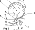
図2,3及び4には、グリッパ装置2が、次のフラット材料シートBを取りに行くのに、シート受取りローラ3をかすめて上側の死点位置へと戻り揺動可能とするために、シート受取りローラ3が、自体公知の形式で円形ではなく、楕円形に形成されていることが示されている。
2, 3, and 4, in order for the
特に図2〜4に示されているように、図示の実施の形態では、シート受取りローラ3の軸線11が、変向ローラ9の軸線10の上方に実質的に鉛直に位置する。以下に、このことから生じる、シート受取りローラ3からサクションベルト7へのフラット材料シートBの受渡しの経過について詳述する。
In particular, as shown in FIGS. 2 to 4, in the illustrated embodiment, the
図2で見て、シート受取りローラ3のローラグリッパ4は6時の位置にある。ローラグリッパ4は、その閉鎖された位置にあり、フラット材料シートBの前縁を形状結合(formschluessig:形状による束縛)式に保持する。少なくとも、図2で見てフラット材料シートBにより被覆されるサクション穴5は、グリッパ装置2によるフラット材料シートBの先行の受渡しの枠内で、シート受取りローラ3の回転方向Rとは逆向きに漸次、既にサクションエアによって負荷され、少なくともサクション穴5の大部分は、フラット材料シートBと接触している。図2に示すように、ボール紙からなるフラット材料シートBの曲げ剛性は、フラット材料シートBの後端側の、つまり図2で見て右側の領域がシート受取りローラ3に当接しないようになっていてよい。
As shown in FIG. 2, the
図2にはさらに、サクションボックス16が右方に、変向ローラ9の可及的近傍に近接されていることが示されている。それでもなお、吸引作用のないゾーンSZが、サクションベルト7の、搬送平面TEを形成する表面上に生じる。
FIG. 2 further shows that the
サクションベルト7へのフラット材料シートBの、滑りがなく、ひいては見当合わせが正しい受渡しは、吸引作用のないゾーンSZに関して、種々異なる形態で実施可能である。
The delivery of the flat material sheet B to the
フラット材料シートBをサクションベルト7に受け渡す第1の方法形態の枠内で、ローラグリッパ4は、シート受取りローラ3の、図2に示した6時の位置ではまだ開放されておらず、かつ少なくともフラット材料シートBにより被覆されたサクション穴5は、依然としてサクションエアによって、図3に示した回転位置にシート受取りローラ3が到達するまで負荷されている。
Within the frame of the first method form for delivering the flat material sheet B to the
シート受取りローラ3の、図3で達成された回転位置において、ローラグリッパ4は、サクションボックス16の延在により規定されるサクションベルト7の吸引ゾーンのちょうど始端にある。ほぼこの瞬間に、ローラグリッパ4は開放されて、フラット材料シートBの前縁を解放する。さらに、サクション穴5により形成されるサクション穴列のサクションエア負荷は、自体公知の適当な制御弁によって遮断、詳細には時間的に均等な間隔を置いて、まず図3で見て最も左側の、ローラグリッパ4の直後にあるサクション穴列が吸引作用を失い、次いで図3で見て左から2番目、3番目、・・・、最終的に漸次すべてのサクション穴列が吸引作用、ひいては保持力を、もはやフラット材料シートBに対して及ぼさないように遮断される。その際、それぞれのサクション穴列のサクションエア負荷の遮断は、常に、サクション穴列がほぼ6時の位置にあるときに実施される。
In the rotational position achieved in FIG. 3 of the
フラット材料シートBをサクションベルト7に受け渡す第2の方法形態は、第1の方法形態とは、ローラグリッパ4が既に、図2に示した6時の位置にあるときに開放される点で相違する。これにより、ローラグリッパ4は、フラット材料シートBの前縁の運動方向が搬送平面TE内にあるとき、その開放位置へと運動する。それに応じて、フラット材料シートBの前縁は、搬送平面TEから上方へ持ち上げられることなく、サクションベルト7上に到達し、吸引作用のないゾーンSZにおいて、専らシート受取りローラ3内に設けられたサクション穴5によって搬送される。サクション穴列のサクションエア負荷の漸次の遮断は、この実施の形態においてもそれぞれ6時の位置で実施される。
The second method form for delivering the flat material sheet B to the
どのようにフラット材料シートBがサクションベルト7に受け渡されるかにかかわらず、フラット材料シートBの、図4に示した徐々に増加する領域ZBが生じる。この増加する領域ZBにおいて、フラット材料シートBは、サクションボックス16により吸い込まれるサクションエアによって、サクションベルト7の表面に保持される。増加する領域ZBは、フラット材料シートBの前縁において始まり、サクションボックス16の、図4で見て右側の端部まで延在する。増加する領域ZBの面積が増加する割合で、フラット材料シートBがなおシート受取りローラ3に保持される領域は減少する。図4には、フラット材料シートBがシート受取りローラ3とサクションベルト7との間の受渡し期間中、専らサクションエアにより保持され、このとき、サクションベルト7がクロック速度で搬送され、かつシート受取りローラ3もクロック速度で追従制御されることが見て取れる。増加する領域ZBが比較的小さく、それゆえにサクションベルト7が僅かな保持力をフラット材料シートBに対して及ぼすにすぎない間は、こうして、本発明により、サクションベルト7とフラット材料シートBとの間にスリップが発生せず、フラット材料シートBが回転式打抜き機の作業ステーションに、正確な位置決めで供給可能であることが保証される。
Regardless of how the flat material sheet B is delivered to the
グリッパ装置2の運動軌道に関してスペース上の関係が許す限り、択一的には、シート受取りローラ3を図2〜図4で見て変向ローラ9の軸線10に対して相対的に左に、場合によっては図2に示した吸引作用のないゾーンSZが、ローラグリッパ4が6時の位置にあるときに既に、回転方向Rで見てローラグリッパ4あるいはフラット材料シートBの前縁の後にあるように、ずらしてもよい。相応に、ローラグリッパ4は、この場合、前記第2の方法形態と同様に6時の位置で開放可能である。
As long as the space relationship with respect to the motion trajectory of the
図2〜図4に示したように、ローラグリッパ4は、半径方向でシート受取りローラ3の周面から突出している。この理由から、サクションベルト7は、図5に示すように、相互の間隔がシート受取りローラ3の軸方向でのローラグリッパ4の間隔に等しい、貫通穴の形態の2つの侵入切欠き8を有する。受渡し行程の開始時(特に図2に示した6時の位置参照)、ローラグリッパ4が侵入切欠き8内に侵入可能であるので、有利には、サクションベルト7の搬送平面TEは、サクション穴5が通走する円軌道の接線方向で位置する。
As shown in FIGS. 2 to 4, the
択一的には、図5に示した、パーフォレーション加工されたサクションベルト7が、長手方向で分割されてもよい。その結果、平行に相並んで延びる、パーフォレーション加工された2つのサクションベルトが生じ、両サクションベルトには、それぞれ1つの侵入切欠き8が形成されている。
Alternatively, the
別の択一的な形態は、サクションベルト搬送装置6に、前記サクションベルト7の代わりに、図6に示すように、例えば4つの、比較的狭幅なサクションベルト12を装着することにある。その際、サクションベルト12は、中間スペース13を備えて、互いに間隔を置いて配置可能であるので、中間スペース13を通してサクションエアが、フラット材料シートBを保持するために吸引可能である。図6に示した実施の形態では、サクションエアの吸込みは、図6に可視のサクションベルト12の下にあるサクションボックスに配置されているサクション開口19を通して実施される。ローラグリッパ4は、それぞれ、サクションベルト12へのフラット材料シートBの受渡しの開始時、相互の間隔が両ローラグリッパ4の間隔に等しい外側の中間スペース13内に侵入する。このことは、前記サクションベルト7に対して、サクションベルト12が確かにクロック速度で駆動されなければならないものの、正確なクロックで、シート受取りローラ3に対して相対的な所定の回転位置を維持しなくてもよいという利点を有する。
Another alternative form is to attach, for example, four relatively
1 装置
2 グリッパ装置
3 シート受取りローラ
4 ローラグリッパ
5 サクション穴
6 サクション搬送装置
7 サクションベルト
8 侵入切欠き
9 変向ローラ
10 変向ローラの軸線
11 シート受取りローラの軸線
12 サクション穴
13 中間スペース
14 ずれ重なり式ストリームフィードベルト
15 パーフォレーション穴
16 サクションボックス
17,18 変向ローラ
19 サクション開口
B フラット材料片
R 回転方向
SZ 吸引作用のないゾーン
TE 搬送平面
ZB 増加する領域
DESCRIPTION OF SYMBOLS 1
Claims (13)
‐該フラット材料片(B)の前縁を把持して、該フラット材料片(B)を加速するためのグリッパ装置(2)と、
‐加速された前記フラット材料片(B)を前記グリッパ装置(2)から受け取るための少なくとも1つのシート受取りローラ(3)とを備え、該シート受取りローラ(3)が、該シート受取りローラ(3)の周囲で働く、加速された前記フラット材料片(B)を把持するための少なくとも1つのローラグリッパ(4)を備え、該ローラグリッパ(4)が、前記フラット材料片(B)を保持する閉鎖位置と、前記フラット材料片(B)を解放する開放位置との間で可動である
形式のものにおいて、
‐前記シート受取りローラ(3)が、該シート受取りローラ(3)の周囲の、回転方向(R)で見て前記ローラグリッパ(4)の後に接続する部分に、サクションエアにより負荷可能な複数のサクション穴(5)を備え、かつ
‐サクションエアにより負荷可能な少なくとも1つのサクションベルト(7)を備えるサクションベルト搬送装置(6)が設けられており、
‐前記閉鎖位置から前記開放位置への前記ローラグリッパ(4)の移行及び前記サクション穴(5)のサクションエア負荷は、前記フラット材料片(B)が実質的にスリップなしに前記シート受取りローラ(3)から前記サクションベルト(7)に受渡し可能であるように制御可能である
ことを特徴とする、フラット材料片を加工するための機械の作業ステーションにフラット材料片を供給し、かつフラット材料片を見当正しく搬送するための装置。An apparatus for feeding a flat material piece (B) to a work station of a machine for processing the flat material piece (B) and for properly conveying the flat material piece (B),
A gripper device (2) for gripping the leading edge of the flat material piece (B) and accelerating the flat material piece (B);
-At least one sheet receiving roller (3) for receiving the accelerated piece of flat material (B) from the gripper device (2), said sheet receiving roller (3) being said sheet receiving roller (3) ) At least one roller gripper (4) for gripping the accelerated flat material piece (B) working around the roller gripper (4), which holds the flat material piece (B) In a type that is movable between a closed position and an open position for releasing said flat material piece (B),
The sheet receiving roller (3) has a plurality of parts that can be loaded by suction air at a portion of the periphery of the sheet receiving roller (3) that is connected after the roller gripper (4) when viewed in the rotational direction (R). A suction belt transport device (6) comprising a suction hole (5) and comprising at least one suction belt (7) capable of being loaded by suction air,
The transition of the roller gripper (4) from the closed position to the open position and the suction air load of the suction hole (5) are such that the flat material piece (B) is substantially free from slipping the sheet receiving roller ( 3) supplying the flat material piece to the work station of the machine for processing the flat material piece, wherein the flat material piece is controllable so that it can be delivered to the suction belt (7) from 3) A device for transporting the register properly.
‐グリッパ装置(2)により前記フラット材料片(B)の前縁を把持して、該フラット材料片(B)を加速させ、かつ
‐加速された前記フラット材料片(B)を少なくとも1つの回転するシート受取りローラ(3)により前記グリッパ装置(2)から受け取り、加速された前記フラット材料片(B)を、前記シート受取りローラ(3)の周囲で働く、前記フラット材料片(B)を保持する閉鎖位置と、前記フラット材料片(B)を解放する開放位置との間で可動な少なくとも1つのローラグリッパ(4)により把持する
というステップを有する、フラット材料片を加工するための機械の作業ステーションにフラット材料片を供給し、かつフラット材料片を見当正しく搬送するための方法において、
‐前記フラット材料片(B)を前記ローラグリッパ(4)に対して付加的に、前記シート受取りローラ(3)の周囲の、回転方向(R)で見て前記ローラグリッパ(4)の後に接続する部分にあるサクション穴(5)により吸引されるサクションエアによって、前記シート受取りローラ(3)の周囲に保持し、
‐前記フラット材料片(B)を前記シート受取りローラ(3)から、サクションベルト搬送装置(6)の、サクションエアにより負荷される少なくとも1つのサクションベルト(7)に、前記ローラグリッパ(4)が前記閉鎖位置から前記開放位置へと運動し、かつ前記サクション穴(5)が、前記ローラグリッパ(4)の直近に位置するサクション穴(5)を始点に前記シート受取りローラ(3)の回転方向(R)とは逆向きに順番に、少なくともサクションエアのない状態に切り換えられることによって受け渡して、前記フラット材料片(B)を、前記シート受取りローラ(3)と前記サクションベルト(7)との間の受渡しプロセス中、面積が増加する領域(ZB)において実質的にスリップなしに前記サクションベルト(7)に保持し、かつ面積が減少するものの、なお前記シート受取りローラ(3)に維持される領域において追従搬送する
ことを特徴とする、フラット材料片を加工するための機械の作業ステーションにフラット材料片を供給し、かつフラット材料片を見当正しく搬送するための方法。A method for feeding a flat material piece (B) to a work station of a machine for processing the flat material piece (B) and for properly conveying the flat material piece (B), comprising the following steps: :
-Gripping the leading edge of the flat material piece (B) by the gripper device (2) to accelerate the flat material piece (B); and-rotating the accelerated flat material piece (B) at least one rotation The flat material piece (B), which is received from the gripper device (2) by the sheet receiving roller (3) and accelerated, works around the sheet receiving roller (3) and holds the flat material piece (B). Machine operation for processing a flat material piece, comprising the step of gripping by at least one roller gripper (4) movable between a closed position to open and an open position to release said flat material piece (B) In a method for feeding flat material pieces to a station and conveying the flat material pieces in a correct manner,
The flat piece of material (B) is additionally connected to the roller gripper (4) and connected around the sheet receiving roller (3) after the roller gripper (4) when viewed in the rotational direction (R) Held around the sheet receiving roller (3) by the suction air sucked by the suction hole (5) in the portion to be
The roller gripper (4) is moved from the sheet receiving roller (3) to the at least one suction belt (7) loaded by the suction air of the suction belt conveying device (6). The rotation direction of the sheet receiving roller (3) starts from the suction hole (5) that moves from the closed position to the open position and the suction hole (5) is positioned in the immediate vicinity of the roller gripper (4). The flat material piece (B) is transferred in the reverse direction to (R) by switching to a state in which at least no suction air exists, and the flat material piece (B) is transferred between the sheet receiving roller (3) and the suction belt (7). Holds on the suction belt (7) with virtually no slip in the area (ZB) where the area increases during the delivery process between The flat material piece is supplied to a work station of a machine for processing the flat material piece, characterized in that it follows and conveys in an area maintained by the sheet receiving roller (3), although the area is reduced. And a method for correctly conveying a flat piece of material.
Applications Claiming Priority (3)
| Application Number | Priority Date | Filing Date | Title |
|---|---|---|---|
| DE102007035435A DE102007035435B4 (en) | 2007-07-28 | 2007-07-28 | Apparatus and method for drawing flat pieces of material and register-accurate transporting the flat pieces of material |
| DE102007035435.7 | 2007-07-28 | ||
| PCT/EP2008/005740 WO2009015761A1 (en) | 2007-07-28 | 2008-07-15 | Apparatus and method for drawing in flat material pieces and in-register transportation of the flat material pieces |
Publications (2)
| Publication Number | Publication Date |
|---|---|
| JP2010534601A JP2010534601A (en) | 2010-11-11 |
| JP4944992B2 true JP4944992B2 (en) | 2012-06-06 |
Family
ID=39942975
Family Applications (1)
| Application Number | Title | Priority Date | Filing Date |
|---|---|---|---|
| JP2010518524A Expired - Fee Related JP4944992B2 (en) | 2007-07-28 | 2008-07-15 | Apparatus and method for feeding flat material pieces and conveying the flat material pieces in a correct manner |
Country Status (5)
| Country | Link |
|---|---|
| US (1) | US8123221B2 (en) |
| EP (1) | EP2170749A1 (en) |
| JP (1) | JP4944992B2 (en) |
| DE (1) | DE102007035435B4 (en) |
| WO (1) | WO2009015761A1 (en) |
Families Citing this family (2)
| Publication number | Priority date | Publication date | Assignee | Title |
|---|---|---|---|---|
| DE102011120476A1 (en) * | 2011-12-08 | 2013-06-13 | Heidelberger Druckmaschinen Aktiengesellschaft | Unround suction wheel |
| US9446612B1 (en) | 2015-12-11 | 2016-09-20 | Xerox Corporation | Multiple-gripper architecture for multi-sheet-length digital printing |
Family Cites Families (20)
| Publication number | Priority date | Publication date | Assignee | Title |
|---|---|---|---|---|
| CH467713A (en) * | 1968-04-19 | 1969-01-31 | De La Rue Giori Sa | Transport device for leaf-shaped objects that works with suction air |
| DE2439790A1 (en) * | 1970-12-24 | 1976-03-11 | Koenig & Bauer Ag | Vacuum suction feed drum for rotary printing machine - has suction holes connected to vacuum pump via sealed chambers and valves |
| DE2063818B2 (en) | 1970-12-24 | 1972-11-30 | Schnellpressenfabrik Koenig & Bauer AG, 8700 Wurzburg | SHEET FEEDING ON PRINTING MACHINES |
| JPS60159747A (en) * | 1984-01-30 | 1985-08-21 | Toppan Printing Co Ltd | Production of reticule mask |
| DE4439808C2 (en) * | 1994-11-08 | 1998-02-19 | Roland Man Druckmasch | Method and device for aligning sheets |
| DE19609991A1 (en) * | 1996-03-14 | 1997-09-18 | Winkler Duennebier Kg Masch | Method and device for aligning flat objects, in particular envelopes |
| JPH10211745A (en) * | 1996-11-28 | 1998-08-11 | Tec Corp | Medium holding device of ink jet printer |
| US5782183A (en) * | 1997-03-07 | 1998-07-21 | Ward Holding Company, Inc. | Pressurized machine for processing blanks |
| DE10014417A1 (en) * | 2000-03-24 | 2001-09-27 | Heidelberger Druckmasch Ag | Device for transporting a sheet for a rotary printing machine |
| AU2001250232B2 (en) * | 2000-05-08 | 2005-07-14 | Kba-Giori S.A. | Device for conveying sheet-like material |
| DE10212273A1 (en) * | 2001-03-26 | 2002-10-10 | Heidelberger Druckmasch Ag | Device for unrolling flat printed material includes guide surface section with suction openings forming successive groups in fluid connection with evacuation system having several chambers with same or different underpressure |
| JP2002338073A (en) * | 2001-05-16 | 2002-11-27 | Printing Bureau Ministry Of Finance | Vacuum suction paper feeding device |
| DE102004003509B4 (en) * | 2003-02-21 | 2019-04-25 | Heidelberger Druckmaschinen Ag | Device for conveying bows |
| DE102004020252B4 (en) * | 2003-05-07 | 2019-03-07 | Heidelberger Druckmaschinen Ag | Device for conveying sheets by a printing machine |
| JP4638165B2 (en) * | 2003-07-16 | 2011-02-23 | ハイデルベルガー ドルツクマシーネン アクチエンゲゼルシヤフト | Machine for processing sheets |
| DE102004058596B4 (en) * | 2003-11-26 | 2017-09-14 | Ebe Hesterman | Device for the finishing of sheet-like substrates on front and back |
| DE10356413A1 (en) * | 2003-11-26 | 2005-06-30 | Ebe Hesterman | Treatment of curved substrates, e.g. printing, comprises feeding the substrate between two rollers and allowing tool sections to act on the substrates in the work gap |
| MX2007002109A (en) * | 2004-08-27 | 2007-09-14 | Kontrelmec S L | Device and method for unloading laminar elements from a roll and transferring stacks of such laminar elements, and roll used for same. |
| US7448625B2 (en) * | 2004-08-30 | 2008-11-11 | Heidelberger Druckmaschinen Ag | Apparatus for conveying a sheet through a printing machine with radially moving suction grippers |
| DE102006015731A1 (en) * | 2006-04-04 | 2007-10-18 | WINKLER + DüNNEBIER AG | Device and method for the spatial alignment of blanks |
-
2007
- 2007-07-28 DE DE102007035435A patent/DE102007035435B4/en not_active Expired - Fee Related
-
2008
- 2008-07-15 US US12/671,160 patent/US8123221B2/en not_active Expired - Fee Related
- 2008-07-15 EP EP08773990A patent/EP2170749A1/en not_active Withdrawn
- 2008-07-15 WO PCT/EP2008/005740 patent/WO2009015761A1/en active Application Filing
- 2008-07-15 JP JP2010518524A patent/JP4944992B2/en not_active Expired - Fee Related
Also Published As
| Publication number | Publication date |
|---|---|
| EP2170749A1 (en) | 2010-04-07 |
| JP2010534601A (en) | 2010-11-11 |
| WO2009015761A1 (en) | 2009-02-05 |
| DE102007035435A1 (en) | 2009-02-05 |
| US20100201060A1 (en) | 2010-08-12 |
| US8123221B2 (en) | 2012-02-28 |
| DE102007035435B4 (en) | 2009-04-16 |
Similar Documents
| Publication | Publication Date | Title |
|---|---|---|
| US9718286B2 (en) | Sheet-transport drum and printing machine with a sheet-transport drum | |
| JP5148469B2 (en) | Bag supply method and apparatus for packaging machine | |
| JPS61124458A (en) | Method and device for aligning sheet in paper-sheet | |
| JP2010064898A (en) | Method and device for supplying sheet to processing machine | |
| JP6584255B2 (en) | Sheet feeding device | |
| JP2013241266A (en) | Sheet conveyance device | |
| US8651161B2 (en) | Sheet-fed offset printing press | |
| JP2010247291A (en) | Flat plate punching device | |
| CN107813620B (en) | Digital printing machine | |
| JP3213687U (en) | Digital printing machine | |
| JP3677239B2 (en) | Suction roller | |
| JP4105497B2 (en) | Method of transporting a sheet of paper with a paper feeder of a printing press that processes the sheet of paper | |
| JP4944992B2 (en) | Apparatus and method for feeding flat material pieces and conveying the flat material pieces in a correct manner | |
| JPH0373748A (en) | Apparatus for taking over printed matter in bucket wheel driven to rotation | |
| JP2003334926A (en) | Sheet-fed rotary press | |
| US20110108197A1 (en) | Sheet overlap device | |
| US8960663B2 (en) | Sheet feeder with two suction wheels | |
| US20110048646A1 (en) | Sheet overlap device | |
| JP2986726B2 (en) | Method and apparatus for controlling sheet supply in a sheet-fed printing press | |
| US20110120656A1 (en) | Sheet overlap device | |
| CN109311612B (en) | Printing device | |
| JP2013241277A (en) | Sheet conveyance device | |
| JP6431773B2 (en) | Printing device that performs multicolor printing on metal sheets | |
| JP6424093B2 (en) | Printing device that performs multicolor printing on metal sheets | |
| JP2014195861A (en) | Automatic plate punching machine and register adjustment method therefor |
Legal Events
| Date | Code | Title | Description |
|---|---|---|---|
| RD04 | Notification of resignation of power of attorney |
Free format text: JAPANESE INTERMEDIATE CODE: A7424 Effective date: 20101228 |
|
| A977 | Report on retrieval |
Free format text: JAPANESE INTERMEDIATE CODE: A971007 Effective date: 20120130 |
|
| TRDD | Decision of grant or rejection written | ||
| A01 | Written decision to grant a patent or to grant a registration (utility model) |
Free format text: JAPANESE INTERMEDIATE CODE: A01 Effective date: 20120203 |
|
| A01 | Written decision to grant a patent or to grant a registration (utility model) |
Free format text: JAPANESE INTERMEDIATE CODE: A01 |
|
| A61 | First payment of annual fees (during grant procedure) |
Free format text: JAPANESE INTERMEDIATE CODE: A61 Effective date: 20120302 |
|
| R150 | Certificate of patent or registration of utility model |
Free format text: JAPANESE INTERMEDIATE CODE: R150 |
|
| FPAY | Renewal fee payment (event date is renewal date of database) |
Free format text: PAYMENT UNTIL: 20150309 Year of fee payment: 3 |
|
| S533 | Written request for registration of change of name |
Free format text: JAPANESE INTERMEDIATE CODE: R313533 |
|
| FPAY | Renewal fee payment (event date is renewal date of database) |
Free format text: PAYMENT UNTIL: 20150309 Year of fee payment: 3 |
|
| R350 | Written notification of registration of transfer |
Free format text: JAPANESE INTERMEDIATE CODE: R350 |
|
| LAPS | Cancellation because of no payment of annual fees |