JP4944908B2 - Harvesting machine - Google Patents

Harvesting machine Download PDF

Info

Publication number
JP4944908B2
JP4944908B2 JP2009002688A JP2009002688A JP4944908B2 JP 4944908 B2 JP4944908 B2 JP 4944908B2 JP 2009002688 A JP2009002688 A JP 2009002688A JP 2009002688 A JP2009002688 A JP 2009002688A JP 4944908 B2 JP4944908 B2 JP 4944908B2
Authority
JP
Japan
Prior art keywords
headlamp
lens
harvesting machine
self
valves
Prior art date
Legal status (The legal status is an assumption and is not a legal conclusion. Google has not performed a legal analysis and makes no representation as to the accuracy of the status listed.)
Expired - Fee Related
Application number
JP2009002688A
Other languages
Japanese (ja)
Other versions
JP2009065989A5 (en
JP2009065989A (en
Inventor
片山  靖彦
宗之 河瀬
保 征矢
学司 川村
修平 池田
忠 楠
Current Assignee (The listed assignees may be inaccurate. Google has not performed a legal analysis and makes no representation or warranty as to the accuracy of the list.)
Kubota Corp
Original Assignee
Kubota Corp
Priority date (The priority date is an assumption and is not a legal conclusion. Google has not performed a legal analysis and makes no representation as to the accuracy of the date listed.)
Filing date
Publication date
Application filed by Kubota Corp filed Critical Kubota Corp
Priority to JP2009002688A priority Critical patent/JP4944908B2/en
Publication of JP2009065989A publication Critical patent/JP2009065989A/en
Publication of JP2009065989A5 publication Critical patent/JP2009065989A5/ja
Application granted granted Critical
Publication of JP4944908B2 publication Critical patent/JP4944908B2/en
Expired - Fee Related legal-status Critical Current
Anticipated expiration legal-status Critical

Links

Images

Description

本発明は、自走機体に搭乗型の運転部を設け、前記自走機体の前部に収穫前処理部を設けた収穫機に関する。   The present invention relates to a harvesting machine in which a self-propelled airframe is provided with a boarding type driving unit, and a pre-harvest processing unit is provided in front of the self-propelled airframe.

従来、例えば特許文献1に示されるように、運転部5の前面部に前照灯6を設け、その上方に作業灯8を設けたものがあった。
また、特許文献2に示されるように、刈取装置1(収穫前処理部に相当)の穀稈搬送部
2上方を覆う防塵カバー3を、前部カバー4と後部カバー5に分割し、前部カバー4を固定するとともに前部カバー4の前端部に前照灯33を取付け、後部カバー5を前方側の開放位置にスライドさせると、後部カバー5が前照灯33の上部を覆い、前照灯33が、通常の前方への照射領域に加えて、後部カバー5の内面で反射する照射領域により分草体25近傍を照射することができるものがあった。
Conventionally, for example, as shown in Patent Document 1, there is a lamp in which a headlamp 6 is provided on the front surface of the operation unit 5 and a work lamp 8 is provided above the headlamp 6.
Moreover, as shown in Patent Document 2, a dustproof cover 3 that covers the upper part of the grain feeder 2 of the reaping device 1 (corresponding to the pre-harvest processing unit) is divided into a front cover 4 and a rear cover 5, and the front part When the cover 4 is fixed and the headlamp 33 is attached to the front end of the front cover 4 and the rear cover 5 is slid to the open position on the front side, the rear cover 5 covers the top of the headlamp 33 and the headlamp In some cases, the lamp 33 can irradiate the vicinity of the herbaceous body 25 by an irradiation region reflected by the inner surface of the rear cover 5 in addition to the normal forward irradiation region.

実開昭62−175834号公報(第3,4頁、第1,3,4図)Japanese Utility Model Publication No. 62-175834 (pages 3, 4 and 1, 3, 4) 特開平10−136758号公報(〔0015〕,〔0024〕段落、図6)Japanese Patent Laid-Open No. 10-136758 (paragraphs [0015] and [0024], FIG. 6)

収穫機によって夜間に作業をする際、前方を前後方向に広い範囲にわたって照明することができると、収穫前処理部の前端付近もさらにその前方も照明されて収穫前処理部を作物に対して位置合わせしやすくなるとともに走行先の状況を確認しやすくなり、作業が行いやすくなる。   When working at night with a harvester, if the front can be illuminated in a wide range in the front-rear direction, the front end of the pre-harvest processing unit is also illuminated in front of it, and the pre-harvest processing unit is positioned with respect to the crop. This makes it easier to match and makes it easier to check the status of the destination, making work easier.

上記した従来の技術を採用して照明範囲を広くすると、照明灯を数多く装備したり、照明装置以外の部材に優れた反射器機能を備えさせたりする必要があり、構造面やコスト面で不利になりがちであった。
また、特許文献2に示される技術を採用すると、収穫前処理部の前端付近が照明されるようにすると、後部カバーを開放位置にすることから、防塵カバーによる防塵作用が低下する問題があった。
If the above-mentioned conventional technology is adopted to widen the illumination range, it is necessary to equip many illumination lamps or to provide an excellent reflector function to members other than the illumination device, which is disadvantageous in terms of structure and cost. Tended to be.
Moreover, when the technique shown in Patent Document 2 is adopted, if the vicinity of the front end of the pre-harvest processing unit is illuminated, the rear cover is placed in an open position, so that there is a problem that the dustproof effect of the dustproof cover is reduced. .

本発明の目的は、広い照明範囲を構造面やコスト面で有利に確保することができ、かつ、作業に支障が出ないようにして確保することができる収穫機を提供することにある。   An object of the present invention is to provide a harvester that can advantageously ensure a wide illumination range in terms of structure and cost, and that can be ensured without impeding work.

本第1発明にあっては
走機体に搭乗型の運転部設けられ
記自走機体の前部に、茎稈引起し装置と分草具と前方を照射する前照灯装置とを有する収穫前処理部設けられ
記分草具及び前記前照灯装置前記収穫前処理部の右及び左の横側部に設けられ
前記前照灯装置に、複数のバルブと、前記複数のバルブを覆う正面視で縦長のレンズと、が備えられ、
前記レンズは、機体側面視で前記レンズの前面が前記茎稈引起し装置の前面に沿うように構成されている。
In the first invention ,
Operation of the riding type are provided in the own run airframe,
The front of the front Symbol self airframe, pre-harvest processing unit is provided with a headlight device for irradiating the front and stems稈引cause device and minute grass tool,
Before SL min grasses instrument and said headlamp apparatus is provided next to the side of the right and left of the pre-harvest processing unit,
The headlamp device includes a plurality of bulbs, and a vertically long lens in front view covering the plurality of bulbs,
The lens is configured such that the front surface of the lens is raised from the side of the fuselage and is along the front surface of the device.

本第2発明にあっては、In the second invention,
前記レンズは、機体側面視で前記茎稈引起し装置の上部と重複するように構成されている。The lens is configured to overlap with the upper part of the stem raising device in a side view of the body.

本第3発明にあっては、In the third invention,
前記レンズは、機体前方に向く前面部と、前記前面部と連続的に形成され、機体横外方向に向く側面部とを備えている。The lens includes a front portion facing the front of the body and a side portion formed continuously with the front portion and facing the lateral direction of the body.

本第発明にあっては
前記レンズは、側面視で縦長に形成されている。
In the fourth invention ,
The lens is formed vertically long in a side view.

本第5発明にあっては、In the fifth invention,
前記レンズのうち前記前面部と前記側面部とに亘る部分が、湾曲した形状に形成されている。A portion of the lens that extends between the front surface portion and the side surface portion is formed in a curved shape.

本第6発明にあっては、In the sixth invention,
前記レンズ全体が、湾曲した形状に形成されている。The entire lens is formed in a curved shape.

本第発明にあっては
前記複数のバルブの夫々は、上下方向に並べて設けられている。
In the seventh invention ,
Each of the plurality of valves is provided side by side in the vertical direction.

本第8発明にあっては、In the eighth invention,
前記バルブの夫々に対応する複数のリフレクタを備え、前記複数のリフレクタは一体的に形成されている。A plurality of reflectors corresponding to each of the valves are provided, and the plurality of reflectors are integrally formed.

本第9発明にあっては、In the ninth invention,
一体的に形成された前記リフレクタは、前記茎稈引起し装置の傾きに沿うように構成されている。The integrally formed reflector is configured so as to follow the inclination of the stem raising device.
本第10発明にあっては、In the tenth invention,
前記複数のバルブの夫々は、最も下側のバルブが最も前方に位置するように、上下方向に並べて設けられている。Each of the plurality of valves is provided side by side in the vertical direction so that the lowermost valve is positioned forward.
本第11発明にあっては、In the eleventh invention,
前記複数のバルブの夫々は、上側になるほど機体後方に位置するように、上下方向に並べて設けられている。Each of the plurality of valves is arranged side by side in the vertical direction so as to be located at the rear of the machine body as it goes upward.
本第12発明にあっては、In the twelfth invention,
前記バルブの夫々に対応する複数のリフレクタを備え、A plurality of reflectors corresponding to each of the valves;
前記複数のバルブの光の夫々が異なる方向に向けて照射されるように、前記複数のバルブ向きと前記複数のリフレクタの向きとが設定されている。The direction of the plurality of bulbs and the direction of the plurality of reflectors are set so that each of the light from the plurality of bulbs is irradiated in different directions.

コンバイン全体の側面図である。It is a side view of the whole combine. 前照灯装置及び側照灯の機体平面視での照射範囲を示す説明図である。It is explanatory drawing which shows the irradiation range in the body planar view of a headlamp apparatus and a sidelight. 刈取り前処理部の斜視図である。It is a perspective view of a pre-cutting processing part. 刈取り前処理部の前面図である。It is a front view of a pre-cutting processing part. 刈取り前処理部の強制分草装置装着要領を示す平面図である。It is a top view which shows the compulsory weeding device mounting | wearing point of a pre-cutting process part. (a)は、作業状態での前照灯装置の機体側面視での照射範囲を示す説明図であり、(b)は、非作業状態での前照灯装置の機体側面視での照射範囲を示す説明図である。(A) is explanatory drawing which shows the irradiation range in the body side view of the headlamp apparatus in a working state, (b) is the irradiation range in the body side view of the headlamp apparatus in a non-working state. It is explanatory drawing which shows. 前照灯装置の横断平面図である。It is a cross-sectional top view of a headlamp apparatus. 側照灯の横断平面図である。It is a cross-sectional plan view of a side lamp. 前照灯装置の縦断側面図である。It is a vertical side view of a headlamp device. リフレクタの正面図である。It is a front view of a reflector. リフレクタの斜視図である。It is a perspective view of a reflector. 前照灯ケースの表面側での斜視図である。It is a perspective view by the surface side of a headlamp case. 前照灯ケースの裏面側での斜視図である。It is a perspective view in the back surface side of a headlamp case. 別の実施形態を備えた前照灯装置の分解状態での斜視図である。It is a perspective view in the disassembled state of the headlamp apparatus provided with another embodiment. 別の実施形態を備えた刈取り前処理部の前面図である。It is a front view of the cutting pre-processing part provided with another embodiment.

以下、本発明の実施例を図面に基づいて説明する。
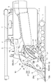
図1,2に示すように、クローラ走行装置1によって自走する自走機体の横方向での一端側の前部に、運転座席2などが装備された搭乗型の運転部3、及び、運転座席2の下方に位置するエンジンが装備された原動部を設け、前記自走機体の機体フレーム4の前部に、刈取り前処理部10の前処理部フレーム本体11の基部を回動自在に連結するとともに、この前処理部フレーム本体11にリフトシリンダ5を連動させ、前記機体フレーム4の後部側に脱穀装置6及び穀粒タンク7を設けて、稲、麦などを収穫するコンバインを構成してある。
Embodiments of the present invention will be described below with reference to the drawings.
As shown in FIGS. 1 and 2, a riding-type driving unit 3 equipped with a driver's seat 2 and the like on the front portion on one side in the lateral direction of the self-propelled aircraft that is self-propelled by the crawler traveling device 1, and driving A driving part equipped with an engine located below the seat 2 is provided, and a base part of the pre-processing part frame body 11 of the pre-cutting processing part 10 is rotatably connected to a front part of the body frame 4 of the self-propelled machine body. In addition, the lift cylinder 5 is interlocked with the pretreatment unit frame main body 11, and the threshing device 6 and the grain tank 7 are provided on the rear side of the machine body frame 4 so as to constitute a combine for harvesting rice, wheat and the like. is there.

すなわち、リフトシリンダ5を伸縮操作すると、このリフトシリンダ5が前処理部フレーム本体11を機体フレーム4に対して上下に揺動操作し、刈取り前処理部10を分草具12や刈取装置14などが地面上近くに位置した下降作業状態と、分道具12などが地面上から高く上昇した上昇非作業状態とに自走機体に対して揺動昇降操作する。刈取り前処理部10を下降作業状態にして自走機体を走行させると、刈取り前処理部10は、自走機体横方向に並ぶ複数個の前記分草具12によって植立穀稈を刈取り対象と非刈取り対象とに分草するとともに刈取り対象の植立穀稈を茎稈引起し経路Rに導入し、各分草具12からの植立穀稈をこの穀稈に対応する茎稈引起し装置13によって引起し処理するとともに一つの前記刈取装置14によって刈取り処理し、刈取装置14からの刈取穀稈を供給装置15によって機体後方向きに搬送して脱穀装置6の脱穀フィードチェーン6aの始端部に供給する。脱穀装置6は、脱穀フィードチェーン6aによって刈取穀稈の株元側を機体後方側に挟持搬送しながらその穂先側を扱室(図示せず)に供給して脱穀処理する。穀粒タンク7は、脱穀装置6からの脱穀粒を回収して貯留していく。   That is, when the lift cylinder 5 is expanded and contracted, the lift cylinder 5 swings the preprocessing unit frame main body 11 up and down with respect to the body frame 4, and the cutting preprocessing unit 10 is moved to the weeding tool 12, the cutting device 14, and the like. The self-propelled body is swung up and down in a descending work state in which the tool is positioned near the ground and a lifting non-working state in which the separation tool 12 and the like are elevated from above the ground. When the pre-cutting processing unit 10 is in the descending work state and the self-propelled machine body is caused to travel, the pre-cutting processing unit 10 uses the plurality of weed tools 12 arranged in the lateral direction of the self-propelled machine body as a target for cutting the planted cereal culm. A device for splitting a non-harvesting target and raising a planted culm to be harvested into a stem R and introducing the planted culm from each weeding tool 12 to a stalk 13 and the reaping process by one of the reaping devices 14, the reaped cereals from the reaping device 14 are conveyed by the feeding device 15 toward the rear of the machine body, and are fed to the start end of the threshing feed chain 6 a of the threshing device 6. Supply. The threshing device 6 supplies the tip side to a handling room (not shown) while squeezing and conveying the stock side of the harvested cereal rice cake to the rear side of the machine body by the threshing feed chain 6a and threshing it. The grain tank 7 collects and stores the threshing grains from the threshing device 6.

刈取り前処理部10についてさらに詳述すると、この刈取り前処理部10は、図1,3などに示す如く構成してある。
すなわち、自走機体前後向きの前記前処理部フレーム本体11、この前処理部フレーム本体11の前端部に中間部が連結された自走機体横向きの支持部材17、この支持部材17の自走機体横方向での複数箇所から自走機体前方向きに延出された分草杆18などによって前処理部フレームを構成し、前記各分草杆18の先端部に前記分草具12を固定し、隣り合う一対の分草杆18どうしの間に前記茎稈引起し経路Rを設けるとともに、各茎稈引起し経路Rの横一端側に、前記茎稈起し装置13を上端側ほど自走機体後方側に位置した傾斜状態で設け、前記分草杆18の基端部にバリカン形の前記刈取装置14を設け、前記引起し装置13の後方に前記供給装置15を設けて構成してある。
The pre-cutting processing unit 10 will be described in further detail. The pre-cutting processing unit 10 is configured as shown in FIGS.
That is, the pretreatment unit frame body 11 facing the front and rear of the self-propelled machine body, the support member 17 facing the self-propelled machine body having an intermediate portion connected to the front end of the pretreatment unit frame body 11, and the self-propelled machine body of the support member 17 A pre-processing part frame is constituted by a weed urn 18 extending in front of the self-propelled aircraft from a plurality of locations in the lateral direction, and the weeding tool 12 is fixed to the tip of each weed urn 18 The stem stem raising path R is provided between a pair of adjacent weed rods 18, and the stem raising device 13 is placed on the lateral end side of each stem stem raising path R toward the upper end side. Provided in an inclined state located on the rear side, the clipper-shaped mowing device 14 is provided at the proximal end of the weed ridge 18, and the supply device 15 is provided behind the pulling device 13.

図1に示すように、刈取り前処理部10の両横側に、茎稈引起し装置13の後側の横側方を覆う横カバー30、供給装置15の上方を覆う防塵カバー19を設けてある。図3,4などに示すように、左右いずれの横カバー30も、自走機体前方向きの前向き面31aを有した前側板部31と、自走機体横外側方向きの横向き面32aを有した横側板部32とを備えるように屈曲成形した屈曲板金で成り、自走機体横方向に並ぶ前記複数個の茎稈引起し装置13のうちの最も横外側に位置する茎稈引起し装置13の引起しケース13bの横外側に連設してある。左右いずれの横カバー30も、これの前記前向き面31aが引起しケース13bの自走機体前方向きの前面13cに沿った状態になるように構成してある。左右いずれの横カバー30の前記前向き面31aも、引起しケース13bの前記前面13cも、上端側ほど自走機体後方側に位置する状態に傾斜した傾斜面になっている。   As shown in FIG. 1, on both sides of the pre-cutting processing unit 10, a horizontal cover 30 that raises the stem and covers the lateral side of the rear side of the device 13 and a dustproof cover 19 that covers the upper side of the supply device 15 are provided. is there. As shown in FIGS. 3 and 4 and the like, each of the left and right lateral covers 30 has a front side plate portion 31 having a forward facing surface 31a facing forward of the self-propelled aircraft body and a lateral surface 32a facing the lateral direction of the self-propelled aircraft body. Of the stalk raising device 13 located on the outermost lateral side of the plurality of stalk raising devices 13, which is formed of a bent sheet metal that is bent so as to be provided with the lateral plate portion 32. The pull-up case 13b is continuously provided on the lateral side. Each of the left and right lateral covers 30 is configured such that the forward facing surface 31a thereof is raised to be in a state along the front surface 13c of the case 13b facing the front of the self-propelled machine body. Both the forward facing surface 31a of the left and right lateral covers 30 and the front surface 13c of the case 13b are inclined so as to be inclined toward the rear side of the self-propelled aircraft toward the upper end side.

図4に破線で示すように、前記各茎稈引起し装置13は、前記引起しケース13bの内部に、無端式の引起しチェーン13dを駆動スプロケット13eと遊転輪体13fとに巻回して設けて構成してある。   As shown by the broken lines in FIG. 4, each of the stalk raising devices 13 has an endless raising chain 13d wound around a drive sprocket 13e and an idler wheel 13f inside the raising case 13b. It is provided and configured.

引起しチェーン13dが前記駆動スプロケット13eによって回動駆動されると、引起しチェーン13dの複数箇所に起伏揺動自在に設けある引起し爪13aが順次に、引起しケース13bの自走機体横方向での一端側の引起し側を上昇移動し、引起しケース13bの自走機体横方向での他端側の戻り側を下降移動する。引起し側を上昇移動する引起し爪13aは、引起しケース13bの内部に位置する起立ガイド(図示せず)による起立操作のために引起しチェーン13dに対して起立した姿勢になって引起し爪13aの先端側が引起しケース13bからその横外側に突出した状態で上昇移動する。引起し爪13aが引起し側の終端部に到達すると、引起しケース13bの内部に位置する倒伏ガイド(図示せず)が倒伏操作するのであり、引起し爪13aは、起立姿勢から倒伏姿勢に姿勢変化して戻り側に移動して引起しケース13bの内部を倒伏姿勢で下降移動し、引起しケース13bの下端部で戻り側から引起し側に戻るようになっている。   When the elevating chain 13d is rotationally driven by the drive sprocket 13e, elevating claws 13a provided at a plurality of positions of the erecting chain 13d so as to be able to be swung up and down are sequentially raised in the transverse direction of the elevating case 13b. The raising side of the one end side is moved up and the return side of the other end side of the case 13b is lowered. The pulling claw 13a that moves upward on the pulling side is lifted for a standing operation by a standing guide (not shown) located inside the pulling case 13b and is raised in a standing posture with respect to the chain 13d. The nail | claw 13a raises and moves in the state which the front end side raised and protruded from the case 13b to the lateral outer side. When the raising claw 13a reaches the end portion on the raising side, the raising guide (not shown) located inside the raising case 13b performs the falling operation, and the raising claw 13a changes from the standing posture to the lying posture. The posture is changed and moved to the return side to be raised and moved down in the lying posture in the case 13b, and is raised to return from the return side to the return side at the lower end portion of the case 13b.

これにより、各茎稈引起し装置13は、引起しケース13bの下端部で戻り側から引起し側に戻って起立姿勢になった引起し爪13aを分草具12からの植立穀稈に係止させ、この植立穀稈を引起しケース13bから自走機体横向きに突出した起立姿勢で上昇移動する引起し爪13aによって引起し処理する。   As a result, each stem-pick-up device 13 raises the raised claw 13a that has been raised from the return side and returned to the upright side at the lower end of the case 13b to the planted culm from the weeding tool 12. The planted cereal is raised and processed by the raising claw 13a that rises and moves up in a standing posture protruding from the case 13b sideways from the case 13b.

図3,4などに示すように、刈取り前処理部10の両横端の角部に、前照灯装置20を茎稈引起し装置13の上端部のやや横外側に位置するように配置して設けてある。   As shown in FIG. It is provided.

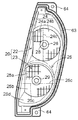
左右いずれの前照灯装置20も、図3,4に示す如く前記横カバー30の前記前側板部31と前記横側板部32とによって形成される角部に設けた前照灯装置組み付け凹部33に自走機体上下方向に並べて配置した一対の前照灯22,23を備えて構成してある。   As shown in FIGS. 3 and 4, the left and right headlamp devices 20 are each provided with a headlamp device assembly recess 33 provided at a corner portion formed by the front plate portion 31 and the side plate portion 32 of the horizontal cover 30. Are provided with a pair of headlamps 22 and 23 arranged side by side in the vertical direction of the self-propelled aircraft.

左右いずれの前照灯装置20においても、次の如く構成してある。
すなわち、横カバー30の前側板部31の前向き面31aは、茎稈引起し装置13の引起しケース13bの前記前面13cに沿って傾斜していることから、前照灯装置組み付け凹部33は、自走機体上方側ほど自走機体後方側に位置する状態に傾斜した傾斜部分に位置している。また、前照灯装置組み付け凹部33は、横カバー30の前記前側板部31と前記横側板部32とにわたって切欠きを設けることによって構成してあることから、自走機体前方向きにも、自走機体横外側向きにも開口した凹部になっており、前照灯装置20は、自走機体の前方向きに照射する他、自走機体横外側向きにも照射しやすくなっている。
Both the left and right headlamp devices 20 are configured as follows.
That is, since the forward facing surface 31a of the front side plate portion 31 of the horizontal cover 30 is inclined along the front surface 13c of the raising case 13b of the stem 13 raising device 13, the headlamp device assembly recessed portion 33 is The upper part of the self-propelled machine body is located on the inclined part that is inclined to be located on the rear side of the self-propelled machine body. In addition, the headlamp assembly recess 33 is formed by providing a notch over the front plate portion 31 and the side plate portion 32 of the horizontal cover 30, so that the self-propelled machine body also faces forward. The headlight device 20 is also radiated toward the front side of the self-propelled aircraft and also easily radiated toward the side of the self-propelled aircraft.

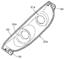
図7,9などに示すように、上下一対の前照灯22,23のうちの上側前照灯22も下側前照灯23も、前記前照灯装置組み付け凹部33の内部で前記横カバー30に固定された前照灯ケース20a、この前照灯ケース20aに止着されたリフレクタ24,25、このリフレクタ24,25の底部に位置するバルブ支持部26,27に支持されたバルブ28,29、前照灯ケース20a前側に装着されたレンズ21を備えて構成してある。上側前照灯22の前照灯ケース20aと、下側前照灯23の前照灯ケース20aとは、一体部品に成形してある。上側前照灯22のリフレクタ24と、下側前照灯23のリフレクタ25とは、一体部品に成形してある。上側前照灯22のレンズ21と、下側前照灯23のレンズ21とは、一体部品に成形してあって、全体として正面視でも側面視でも縦長となっている。そして、図7に示すように、レンズ21は、機体前方に向く前面部121aと、前面部121aと連続的に形成され、機体横外方向に向く側面部121bと、を備えている。図7に示すごとく、レンズ21のうち前面部121aと側面部121bとに亘る部分は、湾曲した形状に形成され、図7及び図9に示すごとく、レンズ21は、全体として湾曲した形状に形成されているAs shown in FIGS. 7, 9, etc., the upper headlamp 22 and the lower headlamp 23 of the pair of upper and lower headlamps 22, 23 are arranged in the lateral cover inside the headlamp assembly recess 33. A headlamp case 20a fixed to the reflector 30, reflectors 24 and 25 fixed to the headlamp case 20a, and bulbs 28 and 27 supported by bulb support portions 26 and 27 located at the bottom of the reflectors 24 and 25, 29, a lens 21 mounted on the front side of the headlamp case 20a is provided. The headlamp case 20a of the upper headlamp 22 and the headlamp case 20a of the lower headlamp 23 are formed as an integral part. The reflector 24 of the upper headlamp 22 and the reflector 25 of the lower headlamp 23 are formed as an integral part. A lens 21 of the upper headlight 22 and the lens 21 of the lower headlamp 23, and has a vertically long integrally molded I tare the part, even a side view in front view as a whole. As shown in FIG. 7, the lens 21 includes a front surface portion 121 a facing forward of the body and a side surface portion 121 b formed continuously with the front surface portion 121 a and facing laterally outward of the body. As shown in FIG. 7, the portion of the lens 21 that extends between the front surface portion 121 a and the side surface portion 121 b is formed in a curved shape, and as shown in FIGS. 7 and 9, the lens 21 is formed in a curved shape as a whole. Has been .

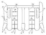
図9,10,11に示すように、下側前照灯23のリフレクタ25に、反射特性が異なる2種のリフレクタ部25a,25bを境界線25cで自走機体上下方向に分かれて位置するようにして設け、上側前照灯22のリフレクタ24に、反射特性が異なる2種のリフレクタ部24a,24bを境界線24cで自走機体横方向に分かれて位置するようにして設けてある。下側前照灯23の2種のリフレクタ部25,25bも、上側前照灯22の2種のリフレクタ部24a,24bも不連続な3次元面を利用して構成してある。   As shown in FIGS. 9, 10, and 11, the reflector 25 of the lower headlamp 23 is positioned so that two kinds of reflector portions 25 a and 25 b having different reflection characteristics are separated in the vertical direction of the self-propelled aircraft at a boundary line 25 c. The reflector 24 of the upper headlamp 22 is provided with two types of reflector portions 24a and 24b having different reflection characteristics so as to be located separately in the lateral direction of the self-propelled aircraft at the boundary line 24c. The two types of reflectors 25 and 25b of the lower headlamp 23 and the two types of reflectors 24a and 24b of the upper headlamp 22 are also configured using discontinuous three-dimensional surfaces.

下側前照灯23の2種のリフレクタ部25a,25bの反射特性は、下側前照灯23のバルブ29から出て2種のリフレクタ部25a,25bのうちの上側リフレクタ部25aで反射して自走機体前方向きに照射される光が自走機体下方向きの照射向きで、かつ最も横端に位置する分草具12の先端部が照射範囲に入る状態に照射され、下側前照灯23のバルブ29から出て2種のリフレクタ部25a,25bのうちの下側リフレクタ部25bで反射して自走機体前方向きに照射される光が上側リフレクタ部25aによる照射向きよりも自走機体上向きの照射向きで照射され、刈取り前処理部10が下降作業状態にあれば、下側リフレクタ部25bで自走機体前方向きに照射される光が地面に対して平行又はそれに近い光になる反射特性に設定してある。   The reflection characteristics of the two types of reflector portions 25a and 25b of the lower headlamp 23 are reflected from the upper reflector portion 25a out of the bulb 29 of the lower headlamp 23 and out of the two types of reflector portions 25a and 25b. The light emitted toward the front of the self-propelled aircraft is irradiated in the direction toward the lower side of the self-propelled aircraft, and the tip of the weeding tool 12 located at the most lateral end enters the irradiation range, and the lower headlight The light emitted from the bulb 29 of the lamp 23 and reflected by the lower reflector portion 25b of the two types of reflector portions 25a and 25b and directed toward the front of the self-propelled aircraft is more self-propelled than the direction of irradiation by the upper reflector portion 25a. If the pre-cutting processing unit 10 is irradiated in the upward direction of the airframe and the pre-cutting processing unit 10 is in the descending work state, the light irradiated in the forward direction of the self-propelled airframe by the lower reflector 25b becomes light parallel to or close to the ground. Set to reflection characteristics Are you.

上側前照灯22の2種のリフレクタ部24a,24bの反射特性は、上側前照灯22のバルブ28から出て2種のリフレクタ部24a,24bのうちの内側リフレクタ部24aで反射して自走機体前方向きに照射される光がほぼ直前方向きの照射向きで照射されて刈取り前処理部10の自走機体横方向での中心よりやや自走機体横外側で前方を照射し、上側前照灯22のバルブ28から出て2種のリフレクタ部24a,24bのうちの外側リフレクタ部24bで反射して自走機体前方向きに照射される光が内側リフレクタ部24aによる照射向きよりも自走機体横方向での内側向きの照射向きで照射される反射特性に設定してある。   The reflection characteristics of the two types of reflector portions 24a and 24b of the upper headlamp 22 are reflected from the bulb 28 of the upper headlamp 22 and reflected by the inner reflector portion 24a of the two types of reflector portions 24a and 24b. The light radiated in the forward direction of the traveling body is irradiated in the irradiation direction almost immediately before, and the front is irradiated slightly outside the lateral side of the traveling body of the pre-cutting processing unit 10 in the lateral direction, and the upper front side. The light emitted from the bulb 28 of the illumination lamp 22 and reflected by the outer reflector 24b of the two types of reflectors 24a and 24b and emitted toward the front of the self-propelled aircraft is more self-propelled than the direction of irradiation by the inner reflector 24a. The reflection characteristics are set so that the light is irradiated in the inward irradiation direction in the lateral direction of the airframe.

図9,10に示すように、前記両リフレクタ24,25を構成しているリフレクタ部材の下部に上向き反射舌部25dを設けてあるとともに、この上向き反射舌部25dは、バルブ29からの光の一部をリフレクタ部25a,25bによる反射向きよりも上向きに反射させ、これにより、刈取り前処理部10を上昇非作業状態に上昇させた状態において、バルブ29からの光の一部が対向車に向けて照射されないようにしている。   As shown in FIGS. 9 and 10, an upward reflecting tongue 25d is provided at the lower part of the reflector members constituting the reflectors 24 and 25, and the upward reflecting tongue 25d In a state where a part of the light is reflected upward from the direction of reflection by the reflectors 25a and 25b and the pre-cutting processing unit 10 is raised to the non-working state, a part of the light from the bulb 29 is directed to the oncoming vehicle. It is made not to irradiate towards.

図1に示す如く下側前照灯23のバルブ29の光軸29aが最も横端に位置する分草具12の先端12aを通るようにして前照灯装置20を組み付けてある。   As shown in FIG. 1, the headlamp device 20 is assembled so that the optical axis 29a of the bulb 29 of the lower headlamp 23 passes through the tip 12a of the weeding tool 12 located at the most lateral end.

左側の前照灯装置20において、図7に示すように、上側前照灯22及び下側前照灯23のバルブ28,29は、自走機体の前後向きに対して約15度の傾斜角度Aで左横外向きに傾斜した取り付け姿勢で支持されている。図示しないが、右側の前照灯装置20において、上側前照灯22及び下側前照灯23のバルブ28,29は、自走機体の前後向きに対して約15度の傾斜角度Aで右横外向きに傾斜した取り付け姿勢で支持されている。   In the left headlamp device 20, as shown in FIG. 7, the valves 28 and 29 of the upper headlamp 22 and the lower headlamp 23 are inclined at about 15 degrees with respect to the front-rear direction of the self-propelled aircraft. A is supported in a mounting posture inclined leftward and outward at A. Although not shown, in the right headlamp device 20, the bulbs 28 and 29 of the upper headlamp 22 and the lower headlamp 23 are positioned at a right angle of about 15 degrees with respect to the front-rear direction of the self-propelled aircraft. It is supported in a mounting posture inclined laterally outward.

図1に示すように、刈取り前処理部10の両横側のうち、運転部3に対して遠い方の横側に、側照灯40を設けてある。   As shown in FIG. 1, side lighting 40 is provided on the lateral side farther from the driving unit 3, on both lateral sides of the pre-cutting processing unit 10.

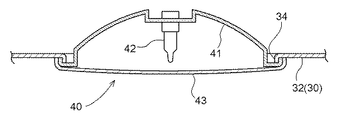
図8に示すように、前記側照灯40は、前記横カバー30の前記横側板部32に貫通孔を備えさせて設けた側照灯組み付け凹部34に配置して横カバー30に固定されたリフレクタ41と、このリフレクタ41に支持されたバルブ42と、リフレクタ41の前部に止着されたレンズ43とを備えて構成してある。   As shown in FIG. 8, the side lamp 40 is fixed to the side cover 30 by being arranged in a side lamp assembly recess 34 provided with a through hole in the side plate portion 32 of the side cover 30. A reflector 41, a valve 42 supported by the reflector 41, and a lens 43 fixed to the front portion of the reflector 41 are provided.

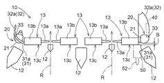
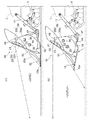
これにより、図2に側照灯40による照射範囲を示し、図2に刈取り前処理部10が下降作業状態に下降された際に左右の前照灯装置20によって照射される自走機体平面視での照射範囲を示し、図6(a)に刈取り前処理部10が下降作業状態に下降された際に左右の前照灯装置20が照射する自走機体側面視での照射範囲を示し、図6(b)に刈取り前処理部10がストロークエンドまで上昇した上昇非作業状態に上昇された際に左右の前照灯装置20が照射する自走機体側面視での照射範囲を示すように、収穫作業を行なう際、夜間であっても、刈取り前処理部10を下降作業状態に下降させることから、左側の前照灯装置20の上側前照灯22と下側前照灯23とによって車体横方向に並ぶ前記分草具12のうちの最も車体左横外側に位置する分草具12の先端部、及びこの分草具12の左横外側方と前方の地面上を照射する照射範囲LDを照射しながら、右側の前照灯装置20の上側前照灯22と下側前照灯23とによって車体横方向に並ぶ前記分草具12のうちの最も車体右横外側に位置する分草具12の先端部、及びこの分草具12の右横外側方と前方の地面上を照射する照射範囲RDを照射しながら作業を行なうことができる。このとき、左側の前照灯装置20の上側前照灯22や下側前照灯23による自走機体横外側向きの照明に併せ、側照灯40による照明範囲Sの照明によっても刈取り前処理部10の横端付近で未刈り穀稈を照明し、殊に未刈り穀稈の株元付近を照明し、分草具12を未刈り穀稈に対して位置合わせしやすくなっている。   2 shows the irradiation range by the side lamp 40, and FIG. 2 shows a plan view of the self-propelled aircraft irradiated by the left and right headlamp devices 20 when the pre-cutting processing unit 10 is lowered to the lowering work state. 6 (a) shows the irradiation range in a side view of the self-propelled aircraft that the left and right headlamp devices 20 irradiate when the pre-cutting processing unit 10 is lowered to the descending work state. FIG. 6B shows the irradiation range in the side view of the self-propelled aircraft that the left and right headlamp devices 20 irradiate when the pre-cutting processing unit 10 is raised to the lifted non-working state that has been raised to the stroke end. When the harvesting operation is performed, the mowing pretreatment unit 10 is lowered to the lowering operation state even at night, and therefore the upper headlamp 22 and the lower headlamp 23 of the left headlamp device 20 are used. Of the weeding tools 12 arranged in the lateral direction of the vehicle body, the vehicle body left lateral outermost The upper headlamp 22 of the right headlamp device 20 is irradiated while irradiating the front end portion of the weeding tool 12 and the irradiation range LD that irradiates the left lateral outer side of the weeding tool 12 and the front ground. And the lower headlamp 23, the distal end portion of the weeding tool 12 located on the outermost right side of the weeding tool 12 among the weeding tools 12 arranged in the lateral direction of the car body, and the right lateral outer side of the weeding tool 12, The work can be performed while irradiating the irradiation range RD for irradiating the front ground. At this time, pre-cutting processing is also performed by illumination in the illumination range S by the side lamp 40 in addition to the illumination of the self-propelled vehicle body laterally outward by the upper head lamp 22 and the lower head lamp 23 of the left head lamp device 20. Illuminating the uncut grain halves near the lateral end of the section 10, in particular, illuminating the vicinity of the roots of the uncut grain cereals, makes it easy to align the weeding tool 12 with the uncut grain culms.

路上走行など非作業状態で走行する際、夜間であっても、刈取り前処理部10をストロークエンドまで上昇させた上昇非作業状態に上昇させることにより、左側の前照灯装置20の上側前照灯22と下側前照灯23とにより、刈取り前処理部10が下降作業状態にある場合の前記照射範囲LDよりも自走機体から前方に離れた地面上を照射する照射範囲LUを照射しながら、右側の前照灯装置20上側前照灯22と下側前照灯23とにより、刈取り前処理部10が下降作業状態にある場合の前記照射範囲RDよりも自走機体から前方に離れた地面上を照射する照射範囲RUを照射しながら走行することができる。このとき、前記上向き反射舌部25dによる上向き反射により、対向車に眩しさを与えにくいように前方を照明しながら走行することができる。 When traveling in a non-working state such as on the road, the upper headlight of the left headlight device 20 is raised by raising the pre-cutting processing unit 10 to the stroke non-working state even at night. The lamp 22 and the lower headlamp 23 irradiate an irradiation range LU that irradiates the ground surface farther away from the self-propelled aircraft than the irradiation range LD when the pre-cutting processing unit 10 is in the descending work state. However , the upper headlamp 22 and the lower headlamp 23 of the right headlamp device 20 move forward from the self-propelled aircraft relative to the irradiation range RD when the pre-cutting processing unit 10 is in the lowering work state. It is possible to travel while irradiating an irradiation range RU that irradiates on a remote ground. At this time, it is possible to travel while illuminating the front so that the oncoming vehicle is less likely to be dazzled by the upward reflection by the upward reflection tongue 25d.

左右いずれの前照灯装置20においても、図5に示すように、上側前照灯22も下側前照灯23も茎稈引起し装置13の引起しケース13bの前記前面13cよりも自走機体後方側に後退差Bだけ後退して位置した状態になるように、両前照灯22,23のレンズ21の外側面が引起しケース13bの前面13cよりもやや自走機体後方側に後退して位置するようにして前照灯装置20を前照灯装置組み付け凹部33に組み付けてある。これにより、図4,5に二点鎖線で示す如く最も横端に位置する茎稈引起し装置13の前側に強制分草装置50を装着する際、前照灯装置20が障害物になりにくくて強制分草装置50が茎稈引起し装置13の引起しケース13bの前面13cに接近して沿いやすくなっている。
強制分草装置50は、分草ケース51から自走機体前方側に突出した状態で上昇移動する分草爪52によって植立穀稈を刈取り対象と非刈取り対象とに分草するものである。
In both the left and right headlamp devices 20, as shown in FIG. 5, both the upper headlamp 22 and the lower headlamp 23 raise the stems and are self-propelled from the front surface 13c of the raising case 13b of the device 13. The outer surfaces of the lenses 21 of both headlamps 22 and 23 are raised so as to be in a state of being moved backward by a backward difference B toward the rear side of the machine body, and slightly backward from the front surface 13c of the case 13b. Thus, the headlamp device 20 is assembled in the headlamp device assembling recess 33. 4 and 5, when the forced weeding device 50 is mounted on the front side of the stalk raising device 13 located at the most lateral end as shown by a two-dot chain line, the headlamp device 20 is unlikely to become an obstacle. Thus, the forced weeding device 50 raises the stem and raises the device 13 so as to approach the front surface 13c of the raising case 13b and easily follow it.
The forced weeding device 50 divides the planted cereals into a cutting target and a non-cutting target by the weed claw 52 that moves upward from the weeding case 51 in a state of protruding to the front side of the self-propelled aircraft.

尚、図1,3に示すように、左右いずれの横カバー30も、一対のキャッチャー35を係合状態と係合解除状態とに切換え操作するだけで操作容易に脱着することができるように構成した下部カバー30aと、この下部カバー30aとは別部品になっているとともに前記前照灯装置20及び側照灯40を備えた上部カバー30bとによって構成してある。   As shown in FIGS. 1 and 3, the left and right lateral covers 30 can be easily detached by simply switching the pair of catchers 35 between the engaged state and the disengaged state. The lower cover 30a and the lower cover 30a are separate parts, and the upper cover 30b includes the headlight device 20 and the sidelight 40.

図9,13に示すように、前記前照灯ケース20aの裏面側に、下側前照灯23のリフレクタ25が入り込む前向き凹部60aの裏側に位置する凹部60、上側前照灯22のリフレクタ24が入り込む前向き凹部61aの裏側に位置する凹部61、一方の凹部61を挟んで前照灯装置上下方向に並んだ状態で突出する一対の取り付け脚部62,62を設けてある。各取り付け脚部62は、前照灯装置20を横カバー30の支持部(図示せず)に連結するものである。図12に示すように、前記前照灯ケース20aの表面側に、レンズ21の全周囲での端部が当て付けられるレンズ当て部63を閉ループ形状に形成して設け、前照灯ケース20aの前記レンズ当て部63の外側に位置する角部に、レンズ21が締め付け連結されるレンズ連結部64を設けてある。これにより、前照灯ケース20a及び前照灯装置20は、剛性が向上した構造を備えた状態になっている。   As shown in FIGS. 9 and 13, the concave portion 60 located on the back side of the forward concave portion 60 a into which the reflector 25 of the lower headlamp 23 enters the back side of the headlamp case 20 a, and the reflector 24 of the upper headlamp 22. Is provided with a pair of mounting legs 62 and 62 projecting in a state of being arranged in the vertical direction of the headlamp device with one recess 61 interposed therebetween. Each mounting leg portion 62 connects the headlamp device 20 to a support portion (not shown) of the lateral cover 30. As shown in FIG. 12, a lens abutting portion 63 is provided on the front side of the headlamp case 20a in a closed loop shape to which an end portion of the entire lens 21 is abutted. A lens connecting portion 64 to which the lens 21 is fastened and connected is provided at a corner located outside the lens abutting portion 63. Thereby, the headlamp case 20a and the headlamp apparatus 20 are in a state of having a structure with improved rigidity.

〔別実施形態〕
図14は、別の実施形態を備えた前照灯装置20を示し、この前照灯装置20にあっては、レンズ21に、上側前照灯22のバルブ28に対応する上側屈折投光部21a、及び、下側前照灯23のバルブ29に対応する下側屈折投光部21bを設けてある。
上側屈折投光部21aには、バルブ28から出て上側屈折投光部21aから照射される光が前記2種のリフレクタ部24a,24bを備えた上側前照灯22による照射範囲と同様の照射範囲に照射されるように、バルブ28からの光を屈折投光する屈折特性を備えてある。下側屈折投光部21bには、バルブ29から出て下側屈折投光部21bから照射される光が前記2種のリフレクタ部25a,25bを備えた下側前照灯23による照射範囲と同様の照射範囲に照射されるように、バルブ29からの光を屈折投光する屈折特性を備えてある。
[Another embodiment]
FIG. 14 shows a headlamp device 20 having another embodiment. In the headlamp device 20, an upper refractive projector corresponding to the bulb 28 of the upper headlamp 22 is provided on the lens 21. 21a and a lower refraction / projection unit 21b corresponding to the bulb 29 of the lower headlamp 23 are provided.
On the upper refractive projector 21a, the light emitted from the bulb 28 and irradiated from the upper refractive projector 21a is irradiated in the same range as the irradiation range by the upper headlamp 22 provided with the two types of reflectors 24a and 24b. A refraction characteristic for refracting and projecting light from the bulb 28 is provided so as to irradiate the area. In the lower refractive projector 21b, the light emitted from the lower refractive projector 21b from the bulb 29 is irradiated by the lower headlamp 23 provided with the two types of reflectors 25a and 25b. A refraction characteristic of refracting and projecting light from the bulb 29 is provided so that a similar irradiation range is irradiated.

この左右の前照灯装置20にあっては、前照灯装置20の照射範囲がレンズ21の上側屈折投光部21a及び下側屈折投光部21bによる屈折特性によって設定されており、これにより、リフレクタ部24a,24b,25a,25bを備えた前照灯装置20と同様に分草具12の先端部及び分草具12の前方を照明する。   In the left and right headlamp devices 20, the irradiation range of the headlamp device 20 is set by the refractive characteristics of the upper refractive projector 21a and the lower refractive projector 21b of the lens 21, thereby The front end of the weeding tool 12 and the front of the weeding tool 12 are illuminated in the same manner as the headlamp device 20 having the reflector parts 24a, 24b, 25a, and 25b.

リフレクタ24,25の反射特性と、レンズ21の屈折特性との組み合わせによって前照灯装置20の照射範囲が所定の照射範囲に設定されるように構成して実施してもよい。
この場合も、本発明の目的を達成することができる。従って、リフレクタ部25a及び下側屈折投光部21bを総称して下方照射手段25a,21bと呼称し、リフレクタ部25b及び下側屈折投光部21bを総称して上方照射手段25b,21bと呼称し、リフレクタ部24a及び上側屈折投光部21aを総称して前方照射手段24a,21aと呼称し、リフレクタ部24b及び上側屈折投光部21aを総称して内側照射手段24b,21aと呼称する。
It may be configured and implemented such that the irradiation range of the headlamp device 20 is set to a predetermined irradiation range by a combination of the reflection characteristics of the reflectors 24 and 25 and the refraction characteristics of the lens 21.
Also in this case, the object of the present invention can be achieved. Accordingly, the reflector 25a and the lower refractive projector 21b are collectively referred to as lower irradiation means 25a and 21b, and the reflector 25b and the lower refractive projector 21b are collectively referred to as upper irradiation means 25b and 21b. The reflector 24a and the upper refractive projector 21a are collectively referred to as the front irradiation means 24a and 21a, and the reflector 24b and the upper refractive projector 21a are collectively referred to as the inner irradiation means 24b and 21a.

図15は、別の実施形態を備えたコンバインを示し、このコンバインにあっては、刈取り前処理部10の茎稈引起し装置13の引起しケース13bの前面に前照灯装置20を設けてある。   FIG. 15 shows a combine provided with another embodiment. In this combine, a headlamp device 20 is provided on the front surface of the raising case 13b of the stem raising device 13 of the pre-cutting processing unit 10. is there.

コンバインの他、玉ねぎ、人参など各種の作物を収穫する作業機にも本発明を適用することができる。従って、刈取り前処理部10を収穫前処理部と呼称し、玉ねぎ、人参などを収穫する作業機やコンバインなどを総称して収穫機と呼称する。 In addition to the combine, the present invention can be applied to a working machine that harvests various crops such as onions and carrots. Therefore, mowing and referred to the pre-processing unit 10 and the "pre-harvest processing unit", onions, etc. collectively referred to as the working machine and the combine to harvest such as carrots is referred to as a harvester.

3 運転部
10 刈取り前処理部(収穫前処理部
12 分草具
13 茎稈引起し装置
20 前照灯装置
21 レンズ
24 リフレクタ
25 リフレクタ
28 バルブ
29 バルブ(最も下側のバルブ)
121a 前面部
121b 側面部
3 driving unit 10 pre- harvest processing unit ( pre-harvest processing unit )
12th grass
13 stalk raising device 20 headlight device
21 Lens
24 reflector
25 Reflector
28 Valve
29 Valve (lowermost valve)
121a Front part
121b Side surface

Claims (12)

自走機体に搭乗型の運転部設けられ
記自走機体の前部に、茎稈引起し装置と分草具と前方を照射する前照灯装置とを有する収穫前処理部設けられ
記分草具及び前記前照灯装置前記収穫前処理部の右及び左の横側部に設けられ
前記前照灯装置に、複数のバルブと、前記複数のバルブを覆う正面視で縦長のレンズと、が備えられ、
前記レンズは、機体側面視で前記レンズの前面が前記茎稈引起し装置の前面に沿うように構成されている収穫機。
Operation of the boarding type is provided on self-propelled aircraft,
The front of the front Symbol self airframe, pre-harvest processing unit is provided with a headlight device for irradiating the front and stems稈引cause device and minute grass tool,
Before SL min grasses instrument and said headlamp apparatus is provided next to the side of the right and left of the pre-harvest processing unit,
The headlamp device includes a plurality of bulbs, and a vertically long lens in front view covering the plurality of bulbs,
The said lens is a harvesting machine comprised so that the front surface of the said lens may raise the stalk and may follow the front surface of an apparatus by a body side view .
前記レンズは、機体側面視で前記茎稈引起し装置の上部と重複するように構成されている請求項1に収穫機。The harvesting machine according to claim 1, wherein the lens is configured to overlap with an upper portion of the stem raising device in a side view of the body. 前記レンズは、機体前方に向く前面部と、前記前面部と連続的に形成され、機体横外方向に向く側面部とを備えている請求項1または2に記載の収穫機。The harvesting machine according to claim 1, wherein the lens includes a front surface portion facing forward of the body and a side surface portion formed continuously with the front surface and facing in a laterally outward direction of the body. 前記レンズは、側面視で縦長に形成されている請求項3に記載の収穫機。The harvesting machine according to claim 3, wherein the lens is formed in a vertically long side view. 前記レンズのうち前記前面部と前記側面部とに亘る部分が、湾曲した形状に形成されている請求項3または4に記載の収穫機。The harvester according to claim 3 or 4, wherein a portion of the lens that extends between the front surface portion and the side surface portion is formed in a curved shape. 前記レンズ全体が、湾曲した形状に形成されている請求項3から5の何れか一項に記載の収穫機。The harvester according to any one of claims 3 to 5, wherein the entire lens is formed in a curved shape. 前記複数のバルブの夫々は、上下方向に並べて設けられている請求項1から6の何れか一項に記載の収穫機。The harvester according to any one of claims 1 to 6, wherein each of the plurality of valves is provided side by side in the vertical direction. 前記バルブの夫々に対応する複数のリフレクタを備え、前記複数のリフレクタは一体的に形成されている請求項1から7の何れか一項に記載の収穫機。The harvester according to any one of claims 1 to 7, further comprising a plurality of reflectors corresponding to each of the valves, wherein the plurality of reflectors are integrally formed. 一体的に形成された前記リフレクタは、前記茎稈引起し装置の傾きに沿うように構成されている請求項8に記載の収穫機。The harvester according to claim 8, wherein the integrally formed reflector is configured to follow the inclination of the stem raising device. 前記複数のバルブの夫々は、最も下側のバルブが最も前方に位置するように、上下方向に並べて設けられている請求項1から9の何れか一項に記載の収穫機。The harvesting machine according to any one of claims 1 to 9, wherein each of the plurality of valves is arranged in a vertical direction so that a lowermost valve is positioned forward. 前記複数のバルブの夫々は、上側になるほど機体後方に位置するように、上下方向に並べて設けられている請求項1から10の何れか一項に記載の収穫機。The harvesting machine according to any one of claims 1 to 10, wherein each of the plurality of valves is arranged side by side in a vertical direction so as to be positioned at the rear side of the machine body as it goes upward. 前記バルブの夫々に対応する複数のリフレクタを備え、A plurality of reflectors corresponding to each of the valves;
前記複数のバルブの光の夫々が異なる方向に向けて照射されるように、前記複数のバルブ向きと前記複数のリフレクタの向きとが設定されている請求項1から11の何れか一項に記載の収穫機。The direction of the plurality of bulbs and the direction of the plurality of reflectors are set so that each of the light from the plurality of bulbs is irradiated in different directions. Harvesting machine.
JP2009002688A 2009-01-08 2009-01-08 Harvesting machine Expired - Fee Related JP4944908B2 (en)

Priority Applications (1)

Application Number Priority Date Filing Date Title
JP2009002688A JP4944908B2 (en) 2009-01-08 2009-01-08 Harvesting machine

Applications Claiming Priority (1)

Application Number Priority Date Filing Date Title
JP2009002688A JP4944908B2 (en) 2009-01-08 2009-01-08 Harvesting machine

Related Parent Applications (1)

Application Number Title Priority Date Filing Date
JP2004241247A Division JP4713108B2 (en) 2004-08-20 2004-08-20 Harvesting machine

Publications (3)

Publication Number Publication Date
JP2009065989A JP2009065989A (en) 2009-04-02
JP2009065989A5 JP2009065989A5 (en) 2009-09-10
JP4944908B2 true JP4944908B2 (en) 2012-06-06

Family

ID=40602898

Family Applications (1)

Application Number Title Priority Date Filing Date
JP2009002688A Expired - Fee Related JP4944908B2 (en) 2009-01-08 2009-01-08 Harvesting machine

Country Status (1)

Country Link
JP (1) JP4944908B2 (en)

Families Citing this family (4)

* Cited by examiner, † Cited by third party
Publication number Priority date Publication date Assignee Title
JP5245814B2 (en) * 2008-12-26 2013-07-24 市光工業株式会社 Vehicle lighting
JP5752377B2 (en) * 2010-09-09 2015-07-22 ヤンマー株式会社 Combine
JP2015065920A (en) * 2013-09-30 2015-04-13 三菱農機株式会社 Cockpit of work vehicle
JP6460725B2 (en) * 2014-10-29 2019-01-30 三菱マヒンドラ農機株式会社 Combine

Family Cites Families (8)

* Cited by examiner, † Cited by third party
Publication number Priority date Publication date Assignee Title
JPS55109043A (en) * 1979-02-13 1980-08-21 Fujitsu Ltd Call piling system for optical data transmission
JPS62204442A (en) * 1986-03-03 1987-09-09 Toshiba Corp Optical recording medium and its recording method
JPS6392533A (en) * 1987-09-17 1988-04-23 Minolta Camera Co Ltd Automatic original feeding device
JPS6487937A (en) * 1987-09-30 1989-04-03 Bando Chemical Ind Belt with heat resistant teeth
JP3579915B2 (en) * 1994-04-26 2004-10-20 井関農機株式会社 Combine harvester
JP2002373510A (en) * 2001-06-14 2002-12-26 Ichikoh Ind Ltd Head lamp
JP4122771B2 (en) * 2002-01-08 2008-07-23 市光工業株式会社 head lamp
JP4185827B2 (en) * 2002-09-24 2008-11-26 ヤンマー農機株式会社 Work vehicle lights

Also Published As

Publication number Publication date
JP2009065989A (en) 2009-04-02

Similar Documents

Publication Publication Date Title
JP4944908B2 (en) Harvesting machine
JP2009065989A5 (en)
JP4046711B2 (en) Harvesting machine
JP5612804B2 (en) Harvesting machine
JP5379420B2 (en) Harvesting machine
JP4713108B2 (en) Harvesting machine
JP2014045694A (en) Combine
JP2006055094A (en) Harvester
JP2006006319A (en) Harvester
JP2006055092A (en) Harvester
JP7018761B2 (en) combine
KR100693976B1 (en) Harvester
JP4107608B2 (en) Harvester
JP6887372B2 (en) combine
JP6991055B2 (en) combine
JP5033251B2 (en) Harvesting machine
JP4675423B2 (en) Mowing harvester
JP2008237061A (en) Lighting structure of harvester
JP4825193B2 (en) Harvesting machine
JP5400923B2 (en) Harvesting machine
WO2022190832A1 (en) Harvesting machine
JP5033250B2 (en) Harvesting machine
JP2016054674A (en) Combine-harvester
WO2016038849A1 (en) Combine
JP2008131868A (en) Combine harvester

Legal Events

Date Code Title Description
A621 Written request for application examination

Free format text: JAPANESE INTERMEDIATE CODE: A621

Effective date: 20090129

A521 Request for written amendment filed

Free format text: JAPANESE INTERMEDIATE CODE: A523

Effective date: 20090728

A131 Notification of reasons for refusal

Free format text: JAPANESE INTERMEDIATE CODE: A131

Effective date: 20111110

A521 Request for written amendment filed

Free format text: JAPANESE INTERMEDIATE CODE: A523

Effective date: 20120110

TRDD Decision of grant or rejection written
A01 Written decision to grant a patent or to grant a registration (utility model)

Free format text: JAPANESE INTERMEDIATE CODE: A01

Effective date: 20120202

A01 Written decision to grant a patent or to grant a registration (utility model)

Free format text: JAPANESE INTERMEDIATE CODE: A01

A61 First payment of annual fees (during grant procedure)

Free format text: JAPANESE INTERMEDIATE CODE: A61

Effective date: 20120302

R150 Certificate of patent or registration of utility model

Ref document number: 4944908

Country of ref document: JP

Free format text: JAPANESE INTERMEDIATE CODE: R150

Free format text: JAPANESE INTERMEDIATE CODE: R150

FPAY Renewal fee payment (event date is renewal date of database)

Free format text: PAYMENT UNTIL: 20150309

Year of fee payment: 3

LAPS Cancellation because of no payment of annual fees