JP4944021B2 - Cable and manufacturing method thereof - Google Patents
Cable and manufacturing method thereof Download PDFInfo
- Publication number
- JP4944021B2 JP4944021B2 JP2007516475A JP2007516475A JP4944021B2 JP 4944021 B2 JP4944021 B2 JP 4944021B2 JP 2007516475 A JP2007516475 A JP 2007516475A JP 2007516475 A JP2007516475 A JP 2007516475A JP 4944021 B2 JP4944021 B2 JP 4944021B2
- Authority
- JP
- Japan
- Prior art keywords
- wire
- cable
- fibers
- core
- gpa
- Prior art date
- Legal status (The legal status is an assumption and is not a legal conclusion. Google has not performed a legal analysis and makes no representation as to the accuracy of the status listed.)
- Expired - Fee Related
Links
Images


Classifications
-
- H—ELECTRICITY
- H01—ELECTRIC ELEMENTS
- H01B—CABLES; CONDUCTORS; INSULATORS; SELECTION OF MATERIALS FOR THEIR CONDUCTIVE, INSULATING OR DIELECTRIC PROPERTIES
- H01B5/00—Non-insulated conductors or conductive bodies characterised by their form
- H01B5/08—Several wires or the like stranded in the form of a rope
- H01B5/10—Several wires or the like stranded in the form of a rope stranded around a space, insulating material, or dissimilar conducting material
-
- H—ELECTRICITY
- H01—ELECTRIC ELEMENTS
- H01B—CABLES; CONDUCTORS; INSULATORS; SELECTION OF MATERIALS FOR THEIR CONDUCTIVE, INSULATING OR DIELECTRIC PROPERTIES
- H01B13/00—Apparatus or processes specially adapted for manufacturing conductors or cables
- H01B13/02—Stranding-up
- H01B13/0235—Stranding-up by a twisting device situated between a pay-off device and a take-up device
-
- D—TEXTILES; PAPER
- D07—ROPES; CABLES OTHER THAN ELECTRIC
- D07B—ROPES OR CABLES IN GENERAL
- D07B1/00—Constructional features of ropes or cables
- D07B1/14—Ropes or cables with incorporated auxiliary elements, e.g. for marking, extending throughout the length of the rope or cable
- D07B1/147—Ropes or cables with incorporated auxiliary elements, e.g. for marking, extending throughout the length of the rope or cable comprising electric conductors or elements for information transfer
-
- H—ELECTRICITY
- H01—ELECTRIC ELEMENTS
- H01B—CABLES; CONDUCTORS; INSULATORS; SELECTION OF MATERIALS FOR THEIR CONDUCTIVE, INSULATING OR DIELECTRIC PROPERTIES
- H01B13/00—Apparatus or processes specially adapted for manufacturing conductors or cables
- H01B13/02—Stranding-up
-
- H—ELECTRICITY
- H01—ELECTRIC ELEMENTS
- H01B—CABLES; CONDUCTORS; INSULATORS; SELECTION OF MATERIALS FOR THEIR CONDUCTIVE, INSULATING OR DIELECTRIC PROPERTIES
- H01B5/00—Non-insulated conductors or conductive bodies characterised by their form
- H01B5/08—Several wires or the like stranded in the form of a rope
- H01B5/10—Several wires or the like stranded in the form of a rope stranded around a space, insulating material, or dissimilar conducting material
- H01B5/102—Several wires or the like stranded in the form of a rope stranded around a space, insulating material, or dissimilar conducting material stranded around a high tensile strength core
- H01B5/105—Several wires or the like stranded in the form of a rope stranded around a space, insulating material, or dissimilar conducting material stranded around a high tensile strength core composed of synthetic filaments, e.g. glass-fibres
-
- H—ELECTRICITY
- H01—ELECTRIC ELEMENTS
- H01B—CABLES; CONDUCTORS; INSULATORS; SELECTION OF MATERIALS FOR THEIR CONDUCTIVE, INSULATING OR DIELECTRIC PROPERTIES
- H01B7/00—Insulated conductors or cables characterised by their form
- H01B7/0009—Details relating to the conductive cores
-
- H—ELECTRICITY
- H01—ELECTRIC ELEMENTS
- H01B—CABLES; CONDUCTORS; INSULATORS; SELECTION OF MATERIALS FOR THEIR CONDUCTIVE, INSULATING OR DIELECTRIC PROPERTIES
- H01B9/00—Power cables
- H01B9/008—Power cables for overhead application
Description
一般に、複合体(金属マトリックス複合体(MMC)を含む)が知られている。複合体は、典型的には、繊維、微粒子、ウイスカー、または繊維(たとえば、短繊維または長繊維)で強化されたマトリックスを含む。金属マトリックス複合体の例としては、アルミニウムマトリックス複合ワイヤ(たとえば、アルミニウムマトリックスに埋込まれた炭化ケイ素繊維、炭素繊維、ホウ素繊維、または多結晶アルファアルミナ繊維)、チタンマトリックス複合テープ(たとえば、チタンマトリックスに埋込まれた炭化ケイ素繊維)、および銅マトリックス複合テープ(たとえば、銅マトリックスに埋込まれた炭化ケイ素繊維またはホウ素繊維)が挙げられる。ポリマーマトリックス複合体の例としては、エポキシ樹脂マトリック内の炭素繊維または黒鉛繊維、ポリエステル樹脂内のガラス繊維またはアラミド繊維、ならびにエポキシ樹脂内の炭素繊維およびガラス繊維が挙げられる。 In general, composites (including metal matrix composites (MMC)) are known. Composites typically include a matrix reinforced with fibers, particulates, whiskers, or fibers (eg, short fibers or long fibers). Examples of metal matrix composites include aluminum matrix composite wires (eg, silicon carbide fibers, carbon fibers, boron fibers, or polycrystalline alpha alumina fibers embedded in an aluminum matrix), titanium matrix composite tapes (eg, titanium matrix) And silicon carbide fibers embedded in a copper matrix (eg, silicon carbide fibers or boron fibers embedded in a copper matrix). Examples of polymer matrix composites include carbon fibers or graphite fibers in an epoxy resin matrix, glass fibers or aramid fibers in a polyester resin, and carbon fibers and glass fibers in an epoxy resin.
複合ワイヤ(たとえば、金属マトリックス複合ワイヤ)の1つの使用は、裸架空送電ケーブル内の強化部材としての使用である。ケーブルに対する1つの典型的な必要は、既存の伝送インフラストラクチャの電力伝達容量を増加させる必要によって駆り立てられる。 One use of composite wires (eg, metal matrix composite wires) is as a reinforcing member in bare overhead power transmission cables. One typical need for cables is driven by the need to increase the power transfer capacity of existing transmission infrastructures.
架空送電用途のためのケーブルの望ましい性能要件としては、耐腐食性、環境耐久性(たとえば、UVおよび湿気)、高温における強度の損失に対する耐性、耐クリープ性、ならびに比較的高い弾性率、低密度、低熱膨張係数、高導電性、および高強度が挙げられる。アルミニウムマトリックス複合ワイヤを含む架空送電ケーブルが知られているが、いくつかの用途の場合、たとえば、より望ましい弛み特性が引続き望まれる。 Desired performance requirements for cables for aerial transmission applications include corrosion resistance, environmental durability (eg, UV and moisture), resistance to loss of strength at high temperatures, creep resistance, and relatively high modulus, low density , Low thermal expansion coefficient, high conductivity, and high strength. Overhead power transmission cables including aluminum matrix composite wires are known, but for some applications, for example, more desirable slack characteristics continue to be desired.
一態様において、本発明は、
熱膨張係数を有し、かつ、アラミド、セラミック、ホウ素、ポリ(p−フェニレン−2,6−ベンゾビスオキサゾール)、黒鉛、炭素、チタン、タングステン、または形状記憶合金の少なくとも1つを含む長手方向のコアと、合せてコアの熱膨張係数より大きい熱膨張係数を有する複数のワイヤであって、複数のワイヤが、アルミニウムワイヤ、銅ワイヤ、アルミニウム合金ワイヤ、または銅合金ワイヤの少なくとも1つを含み、複数のワイヤが、コアの周りに撚り合される、複数のワイヤとを含むケーブルであって、長手方向のコアが金属マトリックス複合ワイヤを含む場合、コアが、別個に、アラミド、セラミック、ホウ素、ポリ(p−フェニレン−2,6−ベンゾビスオキサゾール)、黒鉛、炭素、チタン、タングステン、または形状記憶合金の少なくとも1つを含む(すなわち、金属マトリックス複合ワイヤの一部でない)という条件で、ケーブルが20MPa以下(いくつかの実施形態において、19MPa、18MPa、17MPa、16MPA、15Pa、14MPa、13MPa、12MPa、11MPa、10MPa、9MPa、8MPa、7MPa、6MPa、5MPa、4MPa、3MPa、2MPa、1MPa以下、またはさらには0MPa以下;いくつかの実施形態において、0MPaから20MPa、0MPaから15MPa、0MPaから10MPa、または0MPaから5MPaの範囲内)の応力パラメータを有する、ケーブルを提供する。いくつかの実施形態において、複数のワイヤは、少なくとも90MPa、またはさらには少なくとも100MPaの引張破断強度を有する(ASTM B557/B557M(1999))に従って計算された。
In one aspect, the present invention provides
Longitudinal direction having a thermal expansion coefficient and including at least one of aramid, ceramic, boron, poly (p-phenylene-2,6-benzobisoxazole), graphite, carbon, titanium, tungsten, or shape memory alloy And a plurality of wires having a coefficient of thermal expansion greater than that of the core, the plurality of wires including at least one of an aluminum wire, a copper wire, an aluminum alloy wire, or a copper alloy wire A cable comprising a plurality of wires, wherein the plurality of wires are twisted around the core, and the longitudinal core comprises a metal matrix composite wire, the core is separately aramid, ceramic, boron , Poly (p-phenylene-2,6-benzobisoxazole), graphite, carbon, titanium, tungsten, or shape The cable is 20 MPa or less (in some embodiments, 19 MPa, 18 MPa, 17 MPa, 16 MPa, 15 Pa, 14 MPa, 13 MPa, including at least one of the storage alloys (ie, not part of the metal matrix composite wire) 12 MPa, 11 MPa, 10 MPa, 9 MPa, 8 MPa, 7 MPa, 6 MPa, 5 MPa, 4 MPa, 3 MPa, 2 MPa, 1 MPa or less, or even 0 MPa or less; in some embodiments, 0 MPa to 20 MPa, 0 MPa to 15 MPa, 0 MPa to 10 MPa, Or a cable having a stress parameter in the range of 0 MPa to 5 MPa. In some embodiments, the plurality of wires was calculated according to a tensile break strength of at least 90 MPa, or even at least 100 MPa (ASTM B557 / B557M (1999)).
いくつかの実施形態において、コアが、アラミド、セラミック、ホウ素、ポリ(p−フェニレン−2,6−ベンゾビスオキサゾール)、黒鉛、炭素、チタン、タングステン、または形状記憶合金の少なくとも1つの繊維(典型的には連続繊維)を含む。いくつかの実施形態において、コアは、繊維とマトリックス材料(たとえば、金属および/またはポリマー材料)とを含む複合体を含む。 In some embodiments, the core is at least one fiber of aramid, ceramic, boron, poly (p-phenylene-2,6-benzobisoxazole), graphite, carbon, titanium, tungsten, or shape memory alloy (typically (Continuous fiber). In some embodiments, the core comprises a composite comprising fibers and a matrix material (eg, a metal and / or polymer material).
別の態様において、本発明は、本発明によるケーブルを製造する方法であって、
複数のワイヤを長手方向のコアの周りに撚り合せて、予備的な撚り合されたケーブルを提供する工程であって、複数のワイヤが、アルミニウムワイヤ、銅ワイヤ、アルミニウム合金ワイヤ、または銅合金ワイヤの少なくとも1つを含み、コアが、アラミド、セラミック、ホウ素、ポリ(p−フェニレン−2,6−ベンゾビスオキサゾール)、黒鉛、炭素、チタン、タングステン、または形状記憶合金の少なくとも1つを含む工程と、
予備的な撚り合されたケーブルを閉じダイにかけて、ケーブルを提供する工程であって、閉じダイが内径を有し、ケーブルが外径を有し、ダイ内径がケーブル外径の1.00から1.02倍の範囲内である工程とを含む方法を提供する。
In another aspect, the present invention is a method of manufacturing a cable according to the present invention comprising:
Twisting a plurality of wires around a longitudinal core to provide a pre-twisted cable, the plurality of wires being an aluminum wire, a copper wire, an aluminum alloy wire, or a copper alloy wire And the core includes at least one of aramid, ceramic, boron, poly (p-phenylene-2,6-benzobisoxazole), graphite, carbon, titanium, tungsten, or a shape memory alloy. When,
Applying a pre-twisted cable to a closed die to provide a cable, wherein the closed die has an inner diameter, the cable has an outer diameter, and the die inner diameter is 1.00 to 1 of the cable outer diameter. A step that is within the range of .02 times.
ここで使用されるように、次の用語を、ここで特に明記しない限り、示されているように定義する。 As used herein, the following terms are defined as indicated unless otherwise indicated herein.
「セラミック」は、ガラス、結晶セラミック、ガラス−セラミック、およびそれらの組合せを意味する。 “Ceramic” means glass, crystalline ceramic, glass-ceramic, and combinations thereof.
「連続繊維」は、平均繊維直径と比較されると比較的無限である長さを有する繊維を意味する。典型的には、これは、繊維が、少なくとも1×10⁵(いくつかの実施形態において、少なくとも1×10⁶、またはさらには少なくとも1×10⁷)のアスペクト比(すなわち、繊維の長さと繊維の平均直径との比)を有することを意味する。典型的には、そのような繊維は、少なくとも50メートルのオーダの長さを有し、キロメートル以上のオーダの長さを有することさえできる。 “Continuous fiber” means a fiber having a length that is relatively infinite when compared to the average fiber diameter. Typically, this is because the fiber has an aspect ratio (ie, fiber length to fiber) of at least 1 × 10 5 (in some embodiments, at least 1 × 10 6 , or even at least 1 × 10 7 ). Of the average diameter). Typically, such fibers have a length on the order of at least 50 meters and can even have a length on the order of kilometers or more.
「形状記憶合金」は、マルテンサイト変態を経る金属合金を指し、金属合金は、変態温度より低い温度双晶化機構によって変形可能であり、そのような変形は、変態温度より高い温度に加熱すると双晶構造が元の相に戻るときに可逆性である。 "Shape memory alloy" refers to a metal alloy that undergoes a martensitic transformation, and the metal alloy can be deformed by a temperature twinning mechanism that is lower than the transformation temperature, and when such deformation is heated to a temperature higher than the transformation temperature. It is reversible when the twin structure returns to its original phase.
本発明によるケーブルは、たとえば送電ケーブルとして有用である。典型的には、本発明によるケーブルは、向上された弛み特性(すなわち、低減された弛み)を示す。 The cable according to the present invention is useful, for example, as a power transmission cable. Typically, a cable according to the present invention exhibits improved slack characteristics (ie, reduced slack).
本発明は、ケーブル、およびケーブルを製造する方法に関する。本発明による例示的なケーブル10の断面図が、図1に示されている。ケーブル10は、コア12と、撚り合された丸いワイヤ14の2つの層とを含み、コア12は、ワイヤ16(示されているように、複合ワイヤ)を含む。
The present invention relates to a cable and a method of manufacturing the cable. A cross-sectional view of an
本発明による別の例示的なケーブル20の断面図が、図2に示されている。ケーブル20は、コア22と、撚り合されたワイヤ24の3つの層とを含み、コア22は、ワイヤ26(示されているように、複合ワイヤ)を含む。
A cross-sectional view of another
本発明による別の例示的なケーブル30の断面図が、図3に示されている。ケーブル30は、コア32と、撚り合された台形ワイヤ34とを含み、コア32は、ワイヤ36(示されているように、複合ワイヤ)を含む。
A cross-sectional view of another
本発明による別の例示的なケーブル40の断面図が、図4に示されている。ケーブル40は、コア42と、撚り合されたワイヤ44とを含む。
A cross-sectional view of another
いくつかの実施形態において、コアは、少なくとも、約−75℃から約450℃の温度範囲にわたって、約5.5ppm/℃から約7.5ppm/℃の範囲内の長手方向の熱膨張係数を有する。 In some embodiments, the core has a longitudinal coefficient of thermal expansion within the range of about 5.5 ppm / ° C. to about 7.5 ppm / ° C. over a temperature range of at least about −75 ° C. to about 450 ° C. .
コアを構成する材料の例としては、アラミド、セラミック、ホウ素、ポリ(p−フェニレン−2,6−ベンゾビスオキサゾール)、黒鉛、炭素、チタン、タングステン、および/または形状記憶合金が挙げられる。いくつかの実施形態において、材料は繊維(典型的には連続繊維)の形態である。いくつかの実施形態において、アラミドを含むコアは、少なくとも、約20℃から約200℃の温度範囲にわたって、約−6ppm/℃から約0ppm/℃の範囲内の長手方向の熱膨張係数を有する。いくつかの実施形態において、セラミックを含むコアは、少なくとも、約20℃から約600℃の温度範囲にわたって、約3ppm/℃から約12ppm/℃の範囲内の長手方向の熱膨張係数を有する。いくつかの実施形態において、ホウ素を含むコアは、少なくとも、約20℃から約600℃の温度範囲にわたって、約4ppm/℃から約6ppm/℃の範囲内の長手方向の熱膨張係数を有する。いくつかの実施形態において、ポリ(p−フェニレン−2,6−ベンゾビスオキサゾール)を含むコアは、少なくとも、約20℃から約600℃の温度範囲にわたって、約−6ppm/℃から約0ppm/℃の範囲内の長手方向の熱膨張係数を有する。いくつかの実施形態において、黒鉛を含むコアは、少なくとも、約20℃から約600℃の温度範囲にわたって、約−2ppm/℃から約2ppm/℃の範囲内の長手方向の熱膨張係数を有する。いくつかの実施形態において、炭素を含むコアは、少なくとも、約20℃から約600℃の温度範囲にわたって、約−2ppm/℃から約2ppm/℃の範囲内の長手方向の熱膨張係数を有する。いくつかの実施形態において、チタンを含むコアは、少なくとも、約20℃から約800℃の温度範囲にわたって、約10ppm/℃から約20ppm/℃の範囲内の長手方向の熱膨張係数を有する。いくつかの実施形態において、タングステンを含むコアは、少なくとも、約20℃から約1000℃の温度範囲にわたって、約8ppm/℃から約18ppm/℃の範囲内の長手方向の熱膨張係数を有する。いくつかの実施形態において、形状記憶合金を含むコアは、少なくとも、約20℃から約1000℃の温度範囲にわたって、約8ppm/℃から約25ppm/℃の範囲内の長手方向の熱膨張係数を有する。いくつかの実施形態において、ガラスを含むコアは、少なくとも、約20℃から約600℃の温度範囲にわたって、約4ppm/℃から約10ppm/℃の範囲内の長手方向の熱膨張係数を有する。 Examples of the material constituting the core include aramid, ceramic, boron, poly (p-phenylene-2,6-benzobisoxazole), graphite, carbon, titanium, tungsten, and / or shape memory alloy. In some embodiments, the material is in the form of fibers (typically continuous fibers). In some embodiments, the core comprising aramid has a longitudinal coefficient of thermal expansion in the range of about −6 ppm / ° C. to about 0 ppm / ° C. over a temperature range of at least about 20 ° C. to about 200 ° C. In some embodiments, the core comprising the ceramic has a longitudinal coefficient of thermal expansion in the range of about 3 ppm / ° C. to about 12 ppm / ° C. over a temperature range of at least about 20 ° C. to about 600 ° C. In some embodiments, the core comprising boron has a longitudinal coefficient of thermal expansion in the range of about 4 ppm / ° C. to about 6 ppm / ° C. over a temperature range of at least about 20 ° C. to about 600 ° C. In some embodiments, the core comprising poly (p-phenylene-2,6-benzobisoxazole) has at least about −6 ppm / ° C. to about 0 ppm / ° C. over a temperature range of about 20 ° C. to about 600 ° C. The thermal expansion coefficient in the longitudinal direction within the range of In some embodiments, the core comprising graphite has a longitudinal coefficient of thermal expansion in the range of about −2 ppm / ° C. to about 2 ppm / ° C. over a temperature range of at least about 20 ° C. to about 600 ° C. In some embodiments, the carbon-containing core has a longitudinal coefficient of thermal expansion in the range of about −2 ppm / ° C. to about 2 ppm / ° C. over a temperature range of at least about 20 ° C. to about 600 ° C. In some embodiments, the titanium-containing core has a longitudinal coefficient of thermal expansion in the range of about 10 ppm / ° C. to about 20 ppm / ° C. over a temperature range of at least about 20 ° C. to about 800 ° C. In some embodiments, the tungsten-containing core has a longitudinal coefficient of thermal expansion in the range of about 8 ppm / ° C. to about 18 ppm / ° C. over a temperature range of at least about 20 ° C. to about 1000 ° C. In some embodiments, the core comprising the shape memory alloy has a longitudinal coefficient of thermal expansion within the range of about 8 ppm / ° C. to about 25 ppm / ° C. over a temperature range of at least about 20 ° C. to about 1000 ° C. . In some embodiments, the core comprising glass has a longitudinal coefficient of thermal expansion within the range of about 4 ppm / ° C. to about 10 ppm / ° C. over at least the temperature range of about 20 ° C. to about 600 ° C.
コアの繊維の例としては、アラミド繊維、セラミック繊維、ホウ素繊維、ポリ(p−フェニレン−2,6−ベンゾビスオキサゾール)繊維、黒鉛繊維、炭素繊維、チタン繊維、タングステン繊維、および/または形状記憶合金繊維が挙げられる。 Examples of core fibers include aramid fibers, ceramic fibers, boron fibers, poly (p-phenylene-2,6-benzobisoxazole) fibers, graphite fibers, carbon fibers, titanium fibers, tungsten fibers, and / or shape memory. An alloy fiber is mentioned.
例示的なホウ素繊維が、たとえば、マサチューセッツ州ローウェルのテキストロン・スペシャルティ・ファイバーズ・インコーポレイテッド(Textron Specialty Fibers, Inc. of Lowell, MA)から市販されている。典型的には、そのような繊維は、少なくとも50メートルのオーダの長さを有し、キロメートル以上のオーダの長さを有することさえできる。典型的には、連続ホウ素繊維は、約80マイクロメートルから約200マイクロメートルの範囲内の平均繊維直径を有する。より典型的には、平均繊維直径は、150マイクロメートル以下、最も典型的には、95マイクロメートルから145マイクロメートルの範囲内である。いくつかの実施形態において、ホウ素繊維は、少なくとも3GPa、およびまたはさらには少なくとも3.5GPaの平均引張強度を有する。いくつかの実施形態において、ホウ素繊維は、約350GPaから約450GPaの範囲内、またはさらには約350GPaから約400GPaの範囲内のモジュラスを有する。 Exemplary boron fibers are commercially available from, for example, Textron Specialty Fibers, Inc. of Lowell, Mass., Lowell, Massachusetts. Typically, such fibers have a length on the order of at least 50 meters and can even have a length on the order of kilometers or more. Typically, continuous boron fibers have an average fiber diameter in the range of about 80 micrometers to about 200 micrometers. More typically, the average fiber diameter is no greater than 150 micrometers, most typically in the range of 95 micrometers to 145 micrometers. In some embodiments, the boron fibers have an average tensile strength of at least 3 GPa, and or even at least 3.5 GPa. In some embodiments, the boron fibers have a modulus in the range of about 350 GPa to about 450 GPa, or even in the range of about 350 GPa to about 400 GPa.
いくつかの実施形態において、セラミック繊維は、少なくとも1.5GPa、2GPa、3GPa、4GPa、5GPa、6GPa、およびまたはさらには少なくとも6.5GPaの平均引張強度を有する。いくつかの実施形態において、セラミック繊維は、140GPaから約500GPaの範囲内、またはさらには140GPaから約450GPaの範囲内のモジュラスを有する。 In some embodiments, the ceramic fibers have an average tensile strength of at least 1.5 GPa, 2 GPa, 3 GPa, 4 GPa, 5 GPa, 6 GPa, and or even at least 6.5 GPa. In some embodiments, the ceramic fibers have a modulus in the range of 140 GPa to about 500 GPa, or even in the range of 140 GPa to about 450 GPa.
例示的な炭素繊維が、たとえば、ジョージア州アルファレッタのアモコ・ケミカルズ(Amoco Chemicals of Alpharetta, GA)によって、商品名「ソーネル・カーボン(THORNEL CARBON)」で、2000、4000、5,000、および12,000の繊維のトウで、コネチカット州スタンフォードのヘクセル・コーポレーション(Hexcel Corporation of Stamford, CT)、カリフォルニア州サクラメントのグラフィル・インコーポレイテッド(Grafil, Inc. of Sacramento, CA)(三菱レイヨン(Mitsubishi Rayon Co.)の子会社)から、商品名「パイロフィル(PYROFIL)」で、日本、東京の東レ(Toray)、商品名「トレカ(TORAYCA)」で、東邦レーヨン株式会社(Toho Rayon of Japan, Ltd.)、商品名「ベスファイト(BESFIGHT)」で、ミズーリ州セントルイスのゾルテック・コーポレーション(Zoltek Corporation of St. Louis, MO)、商品名「パネックス(PANEX)」および「パイロン(PYRON)」で、ならびにニュージャージー州ワイコフのインコ・スペシャル・プロダクツ(Inco Special Products of Wyckoff, NJ)(ニッケルコーティング炭素繊維)、商品名「12K20」および「12K50」で、販売されている。典型的には、そのような繊維は、少なくとも50メートルのオーダの長さを有し、キロメートル以上のオーダの長さを有することさえできる。典型的には、連続炭素繊維は、約4マイクロメートルから約12マイクロメートル、約4.5マイクロメートルから約12マイクロメートル、またはさらには約5マイクロメートルから約10マイクロメートルの範囲内の平均繊維直径を有する。いくつかの実施形態において、炭素繊維は、少なくとも1.4GPa、少なくとも2.1GPa、少なくとも3.5GPa、またはさらには少なくとも5.5GPaの平均引張強度を有する。いくつかの実施形態において、炭素繊維は、150GPaを超えて450GPa以下、またはさらには400GPa以下のモジュラスを有する。 Exemplary carbon fibers are, for example, 2000, 4000, 5,000, and 12 by the trade name “THORNEL CARBON” by Amoco Chemicals of Alpharetta, GA. 2,000 fiber tow, Hexcel Corporation of Stamford, CT, Grafil, Inc. of Sacramento, CA (Mitsubishi Rayon (Mitsubishi Rayon) Subsidiary)) under the trade name “PYROFIL” in Tokyo, Japan Toray, under the trade name "TORAYCA", Toho Rayon of Japan, Ltd., under the trade name "BESIGHT", Zoltek Corporation of St. Louis, Missouri Louis, MO), trade names “PANEX” and “PYRON”, and Inco Special Products of Wyckoff, NJ (nickel coated carbon fiber), commodity They are sold under the names “12K20” and “12K50”. Typically, such fibers have a length on the order of at least 50 meters and can even have a length on the order of kilometers or more. Typically, continuous carbon fibers have an average fiber in the range of about 4 micrometers to about 12 micrometers, about 4.5 micrometers to about 12 micrometers, or even about 5 micrometers to about 10 micrometers. Has a diameter. In some embodiments, the carbon fibers have an average tensile strength of at least 1.4 GPa, at least 2.1 GPa, at least 3.5 GPa, or even at least 5.5 GPa. In some embodiments, the carbon fiber has a modulus greater than 150 GPa and no greater than 450 GPa, or even no greater than 400 GPa.
例示的な黒鉛繊維が、たとえば、ジョージア州アルファレッタのBPアモコ(BP Amoco of Alpharetta, GA)によって、商品名「T−300」で、1000、3000、および6000の繊維のトウで、販売されている。典型的には、そのような繊維は、少なくとも50メートルのオーダの長さを有し、キロメートル以上のオーダの長さを有することさえできる。典型的には、連続黒鉛繊維は、約4マイクロメートルから約12マイクロメートル、約4.5マイクロメートルから約12マイクロメートル、またはさらには約5マイクロメートルから約10マイクロメートルの範囲内の平均繊維直径を有する。いくつかの実施形態において、黒鉛繊維は、1.5GPa、2GPa、3GPa、またはさらには少なくとも4GPaの平均引張強度を有する。いくつかの実施形態において、黒鉛繊維は、約200GPaから約1200GPa、またはさらには約200GPaから約1000GPaの範囲内のモジュラスを有する。 Exemplary graphite fibers are sold, for example, by BP Amoco of Alphatta, GA under the trade name “T-300” in 1000, 3000, and 6000 fiber tows. Yes. Typically, such fibers have a length on the order of at least 50 meters and can even have a length on the order of kilometers or more. Typically, continuous graphite fibers are average fibers in the range of about 4 micrometers to about 12 micrometers, about 4.5 micrometers to about 12 micrometers, or even about 5 micrometers to about 10 micrometers. Has a diameter. In some embodiments, the graphite fibers have an average tensile strength of 1.5 GPa, 2 GPa, 3 GPa, or even at least 4 GPa. In some embodiments, the graphite fibers have a modulus in the range of about 200 GPa to about 1200 GPa, or even about 200 GPa to about 1000 GPa.
例示的なチタン繊維が、たとえば、ネバダ州ヘンダーソンのタイメット(TIMET, Henderson, NV)から入手可能である。典型的には、そのような繊維は、少なくとも50メートルのオーダの長さを有し、キロメートル以上のオーダの長さを有することさえできる。典型的には、連続チタン繊維は、50マイクロメートルから約250マイクロメートルの範囲内の平均繊維直径を有する。いくつかの実施形態において、チタン繊維は、少なくとも0.7GPa、1GPa、1.5GPa、2GPa、またはさらには少なくとも2.1GPaの平均引張強度を有する。いくつかの実施形態において、セラミック繊維は、約85GPaから約100GPa、またはさらには約85から約95GPaの範囲内のモジュラスを有する。 Exemplary titanium fibers are available, for example, from Timet, Henderson, NV. Typically, such fibers have a length on the order of at least 50 meters and can even have a length on the order of kilometers or more. Typically, continuous titanium fibers have an average fiber diameter in the range of 50 micrometers to about 250 micrometers. In some embodiments, the titanium fibers have an average tensile strength of at least 0.7 GPa, 1 GPa, 1.5 GPa, 2 GPa, or even at least 2.1 GPa. In some embodiments, the ceramic fibers have a modulus in the range of about 85 GPa to about 100 GPa, or even about 85 to about 95 GPa.
例示的なタングステン繊維が、たとえば、カリフォルニア州グローバービーチのカリフォルニア・ファイン・ワイヤ・カンパニー(California Fine Wire Company, Grover Beach, CA)から入手可能である。典型的には、そのような繊維は、少なくとも50メートルのオーダの長さを有し、キロメートル以上のオーダの長さを有することさえできる。典型的には、連続タングステン繊維は、約100マイクロメートルから約500マイクロメートル約150マイクロメートルから約500マイクロメートル、またはさらには約200マイクロメートルから約400マイクロメートルの範囲内の平均繊維直径を有する。いくつかの実施形態において、タングステン繊維は、少なくとも0.7GPa、1GPa、1.5GPa、2GPa、またはさらには少なくとも2.3GPaの平均引張強度を有する。いくつかの実施形態において、タングステン繊維は、400GPaを超えて約420GPa以下、またはさらには415GPa以下のモジュラスを有する。 Exemplary tungsten fibers are available, for example, from the California Fine Wire Company, Grover Beach, CA. Typically, such fibers have a length on the order of at least 50 meters and can even have a length on the order of kilometers or more. Typically, continuous tungsten fibers have an average fiber diameter in the range of about 100 micrometers to about 500 micrometers, about 150 micrometers to about 500 micrometers, or even about 200 micrometers to about 400 micrometers. . In some embodiments, the tungsten fibers have an average tensile strength of at least 0.7 GPa, 1 GPa, 1.5 GPa, 2 GPa, or even at least 2.3 GPa. In some embodiments, the tungsten fibers have a modulus greater than 400 GPa and not greater than about 420 GPa, or even not greater than 415 GPa.
例示的な形状記憶合金繊維が、たとえば、ペンシルバニア州ウェストホワイトランドのジョンソン・マッセイ(Johnson Matthey, West Whiteland, PA)から入手可能である。典型的には、そのような繊維は、少なくとも50メートルのオーダの長さを有し、キロメートル以上のオーダの長さを有することさえできる。典型的には、連続形状記憶合金繊維は、約50マイクロメートルから約400マイクロメートル、約50から約350マイクロメートル、またはさらには約100マイクロメートルから300マイクロメートルの範囲内の平均繊維直径を有する。いくつかの実施形態において、形状記憶合金繊維は、少なくとも0.5GPa、およびまたはさらには少なくとも1GPaの平均引張強度を有する。いくつかの実施形態において、形状記憶合金繊維は、約20GPaから約100GPa、またはさらには約20GPAから約90GPaの範囲内のモジュラスを有する。 Exemplary shape memory alloy fibers are available, for example, from Johnson Matthey, West Whiteland, PA, West Whiteland, PA. Typically, such fibers have a length on the order of at least 50 meters and can even have a length on the order of kilometers or more. Typically, continuous shape memory alloy fibers have an average fiber diameter in the range of about 50 micrometers to about 400 micrometers, about 50 to about 350 micrometers, or even about 100 micrometers to 300 micrometers. . In some embodiments, the shape memory alloy fibers have an average tensile strength of at least 0.5 GPa, and or even at least 1 GPa. In some embodiments, the shape memory alloy fiber has a modulus in the range of about 20 GPa to about 100 GPa, or even about 20 GPA to about 90 GPa.
例示的なアラミド繊維が、たとえば、デラウェア州ウィルミントンのデュポン(DuPont, Wilmington, DE)から、商品名「ケブラー(KEVLAR)」で入手可能である。典型的には、そのような繊維は、少なくとも50メートルのオーダの長さを有し、キロメートル以上のオーダの長さを有することさえできる。典型的には、連続アラミド繊維は、約10マイクロメートルから約15マイクロメートルの範囲内の平均繊維直径を有する。いくつかの実施形態において、アラミド繊維は、少なくとも2.5GPa、3GPa、3.5GPa、4GPa、またはさらには少なくとも4.5GPaの平均引張強度を有する。いくつかの実施形態において、アラミド繊維は、約80GPaから約200GPa、またはさらには約80GPaから約180GPaの範囲内のモジュラスを有する。 An exemplary aramid fiber is available, for example, from DuPont, Wilmington, Del., Under the trade designation “Kevlar”. Typically, such fibers have a length on the order of at least 50 meters and can even have a length on the order of kilometers or more. Typically, continuous aramid fibers have an average fiber diameter in the range of about 10 micrometers to about 15 micrometers. In some embodiments, the aramid fibers have an average tensile strength of at least 2.5 GPa, 3 GPa, 3.5 GPa, 4 GPa, or even at least 4.5 GPa. In some embodiments, the aramid fiber has a modulus in the range of about 80 GPa to about 200 GPa, or even about 80 GPa to about 180 GPa.
例示的なポリ(p−フェニレン−2,6−ベンゾビスオキサゾール)繊維が、たとえば、日本、大阪の東洋紡(Toyobo Co.)から、商品名「ザイロン(ZYLON)」で入手可能である。典型的には、そのような繊維は、少なくとも50メートルのオーダの長さを有し、キロメートル以上のオーダの長さを有することさえできる。典型的には、連続ポリ(p−フェニレン−2,6−ベンゾビスオキサゾール)繊維は、約8マイクロメートルから約15マイクロメートルの範囲内の平均繊維直径を有する。いくつかの実施形態において、ポリ(p−フェニレン−2,6−ベンゾビスオキサゾール)繊維は、少なくとも3GPa、4GPa、5GPa、6GPa、またはさらには少なくとも7GPaの平均引張強度を有する。いくつかの実施形態において、ポリ(p−フェニレン−2,6−ベンゾビスオキサゾール)繊維は、約150GPaから約300GPa、またはさらには約150GPaから約275GPaの範囲内のモジュラスを有する。 An exemplary poly (p-phenylene-2,6-benzobisoxazole) fiber is available, for example, from Toyobo Co., Osaka, Japan, under the trade designation “ZYLON”. Typically, such fibers have a length on the order of at least 50 meters and can even have a length on the order of kilometers or more. Typically, continuous poly (p-phenylene-2,6-benzobisoxazole) fibers have an average fiber diameter in the range of about 8 micrometers to about 15 micrometers. In some embodiments, the poly (p-phenylene-2,6-benzobisoxazole) fiber has an average tensile strength of at least 3 GPa, 4 GPa, 5 GPa, 6 GPa, or even at least 7 GPa. In some embodiments, the poly (p-phenylene-2,6-benzobisoxazole) fiber has a modulus in the range of about 150 GPa to about 300 GPa, or even about 150 GPa to about 275 GPa.
セラミック繊維の例としては、金属酸化物(たとえば、アルミナ)繊維、窒化ホウ素繊維、炭化ケイ素繊維、およびこれらの繊維のいずれかの組合せが挙げられる。典型的には、セラミック酸化物繊維は、結晶セラミック、および/または結晶セラミックおよびガラスの混合物(すなわち、繊維が、結晶セラミック相およびガラス相の両方を含有することができる)である。典型的には、そのような繊維は、少なくとも50メートルのオーダの長さを有し、キロメートル以上のオーダの長さを有することさえできる。典型的には、連続セラミック繊維は、約5マイクロメートルから約50マイクロメートル、約5マイクロメートルから約25マイクロメートル、約8マイクロメートルから約25マイクロメートル、またはさらには約8マイクロメートルから約20マイクロメートルの範囲内の平均繊維直径を有する。いくつかの実施形態において、結晶セラミック繊維は、少なくとも1.4GPa、少なくとも1.7GPa、少なくとも2.1GPa、およびまたはさらには少なくとも2.8GPaの平均引張強度を有する。いくつかの実施形態において、結晶セラミック繊維は、70GPaを超えて約1000GPa以下、またはさらには420GPa以下のモジュラスを有する。 Examples of ceramic fibers include metal oxide (eg, alumina) fibers, boron nitride fibers, silicon carbide fibers, and any combination of these fibers. Typically, the ceramic oxide fibers are crystalline ceramic and / or a mixture of crystalline ceramic and glass (ie, the fibers can contain both a crystalline ceramic phase and a glass phase). Typically, such fibers have a length on the order of at least 50 meters and can even have a length on the order of kilometers or more. Typically, the continuous ceramic fibers are from about 5 micrometers to about 50 micrometers, from about 5 micrometers to about 25 micrometers, from about 8 micrometers to about 25 micrometers, or even from about 8 micrometers to about 20 micrometers. Having an average fiber diameter in the micrometer range; In some embodiments, the crystalline ceramic fibers have an average tensile strength of at least 1.4 GPa, at least 1.7 GPa, at least 2.1 GPa, and or even at least 2.8 GPa. In some embodiments, the crystalline ceramic fibers have a modulus greater than 70 GPa and not greater than about 1000 GPa, or even not greater than 420 GPa.
モノフィラメントセラミック繊維の例としては、炭化ケイ素繊維が挙げられる。典型的には、炭化ケイ素モノフィラメント繊維は、結晶性、および/または結晶セラミックおよびガラスの混合物(すなわち、繊維が、結晶セラミック相およびガラス相の両方を含有することができる)である。典型的には、そのような繊維は、少なくとも50メートルのオーダの長さを有し、キロメートル以上のオーダの長さを有することさえできる。典型的には、連続炭化ケイ素モノフィラメント繊維は、約100マイクロメートルから約250マイクロメートルの範囲内の平均繊維直径を有する。いくつかの実施形態において、結晶セラミック繊維は、少なくとも2.8GPa、少なくとも3.5GPa、少なくとも4.2GPa、およびまたはさらには少なくとも6GPaの平均引張強度を有する。いくつかの実施形態において、結晶セラミック繊維は、250GPaを超えて約500GPa以下、またはさらには430GPa以下のモジュラスを有する。 Examples of monofilament ceramic fibers include silicon carbide fibers. Typically, silicon carbide monofilament fibers are crystalline and / or a mixture of crystalline ceramic and glass (ie, the fibers can contain both a crystalline ceramic phase and a glass phase). Typically, such fibers have a length on the order of at least 50 meters and can even have a length on the order of kilometers or more. Typically, continuous silicon carbide monofilament fibers have an average fiber diameter in the range of about 100 micrometers to about 250 micrometers. In some embodiments, the crystalline ceramic fibers have an average tensile strength of at least 2.8 GPa, at least 3.5 GPa, at least 4.2 GPa, and or even at least 6 GPa. In some embodiments, the crystalline ceramic fibers have a modulus greater than 250 GPa and not greater than about 500 GPa, or even not greater than 430 GPa.
さらに、例示的なガラス繊維が、たとえば、ニューヨーク州コーニングのコーニング・グラス(Corning Glass, Corning NY)から入手可能である。典型的には、連続ガラス繊維は、約3マイクロメートルから約19マイクロメートルの範囲内の平均繊維直径を有する。いくつかの実施形態において、ガラス繊維は、少なくとも3GPa、4GPa、およびまたはさらには少なくとも5GPaの平均引張強度を有する。いくつかの実施形態において、ガラス繊維は、約60GPaから95GPa、または約60GPaから約90GPaの範囲内のモジュラスを有する。 In addition, exemplary glass fibers are available from, for example, Corning Glass, Corning NY, New York. Typically, continuous glass fibers have an average fiber diameter in the range of about 3 micrometers to about 19 micrometers. In some embodiments, the glass fibers have an average tensile strength of at least 3 GPa, 4 GPa, and or even at least 5 GPa. In some embodiments, the glass fiber has a modulus in the range of about 60 GPa to 95 GPa, or about 60 GPa to about 90 GPa.
いくつかの実施形態において、セラミックおよび炭素繊維はトウ形態である。トウは、繊維技術において知られており、ロービング状形態で集められた複数の(個別の)繊維(典型的には少なくとも100の繊維、より典型的には少なくとも400の繊維)を指す。いくつかの実施形態において、トウは、1トウあたり少なくとも780の個別の繊維を含み、いくつかの場合、1トウあたり少なくとも2600の個別の繊維を含む。セラミック繊維のトウは、300メートル、500メートル、750メートル、1000メートル、1500メートル、1750メートル、およびより長いものを含むさまざまな長さで入手可能である。繊維は、円形または楕円形である断面形状を有することができる。炭素繊維のいくつかの実施形態において、トウは、1トウあたり、少なくとも2,000 5,000 12,000、またはさらには少なくとも50,000の個別の繊維を含む。 In some embodiments, the ceramic and carbon fibers are in tow form. Tow is known in the fiber art and refers to a plurality of (individual) fibers (typically at least 100 fibers, more typically at least 400 fibers) collected in a roving-like form. In some embodiments, the tow comprises at least 780 individual fibers per tow, and in some cases at least 2600 individual fibers per tow. Ceramic fiber tows are available in a variety of lengths, including 300 meters, 500 meters, 750 meters, 1000 meters, 1500 meters, 1750 meters, and longer. The fibers can have a cross-sectional shape that is circular or elliptical. In some embodiments of carbon fibers, the tow comprises at least 2,000 5,000 12,000, or even at least 50,000 individual fibers per tow.
アルミナ繊維が、たとえば、米国特許第4,954,462号明細書(ウッド(Wood)ら)および米国特許第5,185,29号明細書(ウッド(Wood)ら)に記載されている。いくつかの実施形態において、アルミナ繊維は、多結晶アルファアルミナ繊維であり、理論酸化物基準で、アルミナ繊維の総重量を基準にして、99重量パーセントを超えるAl2O3と、0.2〜0.5重量パーセントのSiO2とを含む。別の態様において、いくつかの望ましい多結晶アルファアルミナ繊維は、1マイクロメートル未満(またはさらには、いくつかの実施形態において、0.5マイクロメートル未満)の平均粒度を有するアルファアルミナを含む。別の態様において、いくつかの実施形態において、多結晶アルファアルミナ繊維は、少なくとも1.6GPa(いくつかの実施形態において、少なくとも2.1GPa、またはさらには、少なくとも2.8GPa)の平均引張強度を有する。例示的なアルファアルミナ繊維が、ミネソタ州セントポールの3Mカンパニー(3M Company, St. Paul, MN)によって、商品名「ネクステル(NEXTEL)610」で販売されている。 Alumina fibers are described, for example, in US Pat. No. 4,954,462 (Wood et al.) And US Pat. No. 5,185,29 (Wood et al.). In some embodiments, the alumina fibers are polycrystalline alpha alumina fibers, greater than 99 weight percent Al 2 O 3 based on the total weight of the alumina fibers, based on the theoretical oxide, and from 0.2 to 0.5 weight percent SiO 2 . In another aspect, some desirable polycrystalline alpha alumina fibers comprise alpha alumina having an average particle size of less than 1 micrometer (or even in some embodiments, less than 0.5 micrometers). In another aspect, in some embodiments, the polycrystalline alpha alumina fiber has an average tensile strength of at least 1.6 GPa (in some embodiments, at least 2.1 GPa, or even at least 2.8 GPa). Have. An exemplary alpha alumina fiber is sold under the trade designation “NEXTEL 610” by 3M Company, St. Paul, Minn.
アルミノシリケート繊維が、たとえば、米国特許第4,047,965号明細書(カルスト(Karst)ら)に記載されている。例示的なアルミノシリケート繊維が、ミネソタ州セントポールの3Mカンパニーによって、商品名「ネクステル440」、「ネクステル550」、および「ネクステル720」で販売されている。 Aluminosilicate fibers are described, for example, in US Pat. No. 4,047,965 (Karst et al.). Exemplary aluminosilicate fibers are sold under the trade names “Nextel 440”, “Nextel 550”, and “Nextel 720” by the 3M Company of St. Paul, Minnesota.
アルミノボロシリケート繊維が、たとえば、米国特許第3,795,524号明細書(ソウマン(Sowman)ら)に記載されている。例示的なアルミノボロシリケート繊維が、3Mカンパニーによって、商品名「ネクステル312」で販売されている。 Aluminoborosilicate fibers are described, for example, in US Pat. No. 3,795,524 (Sowman et al.). An exemplary aluminoborosilicate fiber is sold by 3M Company under the trade name “Nextel 312”.
窒化ホウ素繊維を、たとえば、米国特許第3,429,722号明細書(エコノミー(Economy))および米国特許第5,780,154号明細書(オカノ(Okano)ら)に記載されているように製造することができる。 Boron nitride fibers are described, for example, as described in US Pat. No. 3,429,722 (Economie) and US Pat. No. 5,780,154 (Okano et al.). Can be manufactured.
例示的な炭化ケイ素繊維が、たとえば、カリフォルニア州サンディエゴのCOIセラミックス(COI Ceramics of San Diego, CA)によって、商品名「ニカロン(NICALON)」で、500の繊維のトウで、日本の宇部興産(Ube Industries)から、商品名「ティラノ(TYRANNO)」で、およびミシガン州ミッドランドのダウ・コーニング(Dow Corning of Midland, MI)から、商品名「シルラミック(SYLRAMIC)」で販売されている。 An exemplary silicon carbide fiber, for example, by COI Ceramics of San Diego, Calif., Under the trade name “NICALON”, 500 fiber tows, Ube, Japan (Ube) It is sold under the trade name "TYRANNO" from Industries and the trade name "SYLRAMIC" from Dow Corning of Midland, MI.
例示的な炭化ケイ素モノフィラメント繊維が、たとえば、マサチューセッツ州ローウェルのテキストロン・スペシャルティ・マテリアルズ(Textron Specialty Materials of Lowell, MA)によって、商品名「SCS−9」、「SCS−6」、および「ウルラ(Ulra)−SCS」で、ならびにバージニア州ゲインズビルのアトランティック・リサーチ・コーポレーション(Atlantic Research Corporation, of Gainesville, VA)から、商品名「トリマーク(Trimarc)」で販売されている。 Exemplary silicon carbide monofilament fibers are available, for example, under the trade designations “SCS-9”, “SCS-6”, and “Ulla” by Textron Specialty Materials of Lowell, Massachusetts. (Ulra) -SCS ", and from Atlantic Research Corporation, Gainesville, Va. Under the trade name" Trimark ".
市販の繊維は、典型的には、潤滑性をもたらすために、かつ取扱いの間繊維ストランドを保護するために、製造の間繊維に加えられる有機サイジング材料を含む。また、サイジングは、ポリマー複合コアワイヤを製造するために、ポリマーでの引抜成形の間の取扱いを助けることができる。サイジングは、たとえば、サイジングを繊維から溶解除去または燃焼除去することによって除去することができる。典型的には、金属マトリックス複合ワイヤを形成する前に、サイジングを除去することが望ましい。 Commercially available fibers typically include an organic sizing material that is added to the fibers during manufacture to provide lubricity and to protect the fiber strands during handling. Sizing can also aid in handling during pultrusion with the polymer to produce a polymer composite core wire. Sizing can be removed, for example, by dissolving or removing the sizing from the fiber. Typically, it is desirable to remove the sizing prior to forming the metal matrix composite wire.
繊維は、たとえば、繊維の湿潤性を向上させるために、繊維と溶融金属マトリックス材料との間の反応を低減または防止するために、コーティングを使用することができる。そのようなコーティング、およびそのようなコーティングを提供するための技術は、繊維および複合技術において知られている。 The fiber can use a coating to reduce or prevent reaction between the fiber and the molten metal matrix material, for example, to improve the wettability of the fiber. Such coatings and techniques for providing such coatings are known in fiber and composite technology.
いくつかの実施形態において、コア内の繊維の数の少なくとも85%(いくつかの実施形態において、少なくとも90%、またはさらには少なくとも95%)が連続している。 In some embodiments, at least 85% (in some embodiments, at least 90%, or even at least 95%) of the number of fibers in the core is continuous.
複合コアおよびワイヤの例示的なマトリックス材料としては、ポリマー(たとえば、エポキシ、エステル、ビニルエステル、ポリイミド、ポリエステル、シアン酸エステル、フェノール樹脂、ビスマレイミド樹脂、および熱可塑性樹脂)および金属(たとえば、高純度(たとえば、99.95%を超える)元素アルミニウム、または純アルミニウムの、銅などの他の元素との合金)が挙げられる。典型的には、金属マトリックス材料は、たとえば、繊維外部上に保護コーティングを提供する必要をなくすために、マトリックス材料が繊維と著しく化学的に反応しない(すなわち、繊維材料に対して比較的化学的に不活性である)ように選択される。例示的な金属マトリックス材料としては、アルミニウム、亜鉛、スズ、マグネシウム、およびそれらの合金(たとえば、アルミニウムおよび銅の合金)が挙げられる。いくつかの実施形態において、マトリックス材料としては、望ましくは、アルミニウムおよびその合金が挙げられる。 Exemplary matrix materials for composite cores and wires include polymers (eg, epoxy, ester, vinyl ester, polyimide, polyester, cyanate ester, phenolic resin, bismaleimide resin, and thermoplastic resin) and metals (eg, high Purity (for example, greater than 99.95%) elemental aluminum, or alloys of pure aluminum with other elements such as copper. Typically, the metal matrix material does not react significantly chemically with the fiber (ie, is relatively chemical with respect to the fiber material, for example, to eliminate the need to provide a protective coating on the fiber exterior. Inactive). Exemplary metal matrix materials include aluminum, zinc, tin, magnesium, and alloys thereof (eg, aluminum and copper alloys). In some embodiments, the matrix material desirably includes aluminum and its alloys.
いくつかの実施形態において、金属マトリックスは、少なくとも98重量パーセントのアルミニウム、少なくとも99重量パーセントのアルミニウム、99.9重量パーセントを超えるアルミニウム、またはさらには99.95重量パーセントを超えるアルミニウム含む。例示的なアルミニウムおよび銅のアルミニウム合金は、少なくとも98重量パーセントのAlと、2重量パーセントまでのCuとを含む。いくつかの実施形態において、有用な合金は、1000、2000、3000、4000、5000、6000、7000、および/または8000系アルミニウム合金(アルミニウム協会(Aluminum Association)の名称)である。より高い純度の金属が、より高い引張強度のワイヤを製造するのに望ましい傾向があるが、金属のより純粋でない形態も有用である。 In some embodiments, the metal matrix comprises at least 98 weight percent aluminum, at least 99 weight percent aluminum, greater than 99.9 weight percent aluminum, or even greater than 99.95 weight percent aluminum. Exemplary aluminum and copper aluminum alloys contain at least 98 weight percent Al and up to 2 weight percent Cu. In some embodiments, useful alloys are 1000, 2000, 3000, 4000, 5000, 6000, 7000, and / or 8000 series aluminum alloys (aluminum association designation). Although higher purity metals tend to be desirable for producing higher tensile strength wires, less pure forms of metals are also useful.
適切な金属が市販されている。たとえば、アルミニウムが、ペンシルバニア州ピッツバーグのアルコア(Alcoa of Pittsburgh, PA)から、商品名「スーパー・ピュア・アルミニウム(SUPER PURE ALUMINUM);99.99%Al」で入手可能である。アルミニウム合金(たとえば、Al−2重量%のCu(0.03重量%の不純物))を、たとえば、ニューヨーク州ニューヨークのベルモント・メタルズ(Belmont Metals, New York, NY)から得ることができる。亜鉛およびスズが、たとえば、ミネソタ州セントポールのメタル・サービシズ(Metal Services, St. Paul, MN)(「純亜鉛」;99.999%の純度および「純スズ」;99.95%の純度)から入手可能である。たとえば、マグネシウムが、英国マンチェスターのマグネシウム・エレクトロン(Magnesium Elektron, Manchester, England)から、商品名「ピュア(PURE)」で入手可能である。マグネシウム合金(たとえば、WE43A、EZ33A、AZ81A、およびZE41A)を、たとえば、コロラド州デンバーのタイメット(TIMET, Denver, CO)から得ることができる。 Suitable metals are commercially available. For example, aluminum is available from Alcoa of Pittsburgh, Pa., Under the trade designation "SUPER PURE ALUMINUM; 99.99% Al". Aluminum alloys (eg, Al-2 wt% Cu (0.03% wt impurities)) can be obtained from, for example, Belmont Metals, New York, NY, New York. Zinc and tin are, for example, Metal Services, St. Paul, Minn. ("Pure Zinc"; 99.999% purity and "Pure Tin"; 99.95% purity). Is available from For example, magnesium is available under the trade designation “PURE” from Magnesium Elektron, Manchester, England, UK. Magnesium alloys (eg, WE43A, EZ33A, AZ81A, and ZE41A) can be obtained, for example, from Timet, Denver, Colorado (TIMET, Denver, CO).
複合コアおよびワイヤは、典型的には、繊維およびマトリックス材料の組合された体積全体を基準にして、少なくとも15体積パーセント(いくつかの実施形態において、少なくとも20、25、30、35、40、45、またはさらには50体積パーセント)の繊維を含む。より典型的には、複合コアおよびワイヤは、繊維およびマトリックス材料の組合された体積全体を基準にして、40から75(いくつかの実施形態において、45から70)体積パーセントの範囲内の繊維を含む。
The composite core and wire are typically at least 15 volume percent (in some embodiments, at least 20, 25, 30, 35, 40, 45, based on the combined combined volume of fiber and matrix material). , Or even 50 volume percent). More typically, the composite core and wire have fibers in the range of 40 to 75 (in some
典型的には、コアの平均直径は、約1mmから約15mmの範囲内である。いくつかの実施形態において、望ましいコアの平均直径は、少なくとも1mm、少なくとも2mm、またはさらには約3mmまでである。典型的には、複合ワイヤの平均直径は、約1mmから12mm、1mmから10mm、1から8mm、またはさらには1mmから4mmの範囲内である。いくつかの実施形態において、望ましい複合ワイヤの平均直径は、少なくとも1mm、少なくとも1.5mm、2mm、3mm、4mm、5mm、6mm、7mm、8mm、9mm、10mm、11mm、またはさらには少なくとも12mmである。 Typically, the average diameter of the core is in the range of about 1 mm to about 15 mm. In some embodiments, the desired average core diameter is at least 1 mm, at least 2 mm, or even up to about 3 mm. Typically, the average diameter of the composite wire is in the range of about 1 mm to 12 mm, 1 mm to 10 mm, 1 to 8 mm, or even 1 mm to 4 mm. In some embodiments, the desired composite wire average diameter is at least 1 mm, at least 1.5 mm, 2 mm, 3 mm, 4 mm, 5 mm, 6 mm, 7 mm, 8 mm, 9 mm, 10 mm, 11 mm, or even at least 12 mm. .
複合コアおよびワイヤを、当該技術において知られている技術を用いて製造することができる。連続金属マトリックス複合ワイヤを、たとえば、連続金属マトリックス浸透プロセスによって製造することができる。1つの適切なプロセスが、たとえば、米国特許第6,485,796号明細書(カーペンター(Carpenter)ら)に記載されている。ポリマーと、繊維とを含むワイヤを、当該技術において知られている引抜成形プロセスによって製造することができる。 Composite cores and wires can be manufactured using techniques known in the art. A continuous metal matrix composite wire can be produced, for example, by a continuous metal matrix infiltration process. One suitable process is described, for example, in US Pat. No. 6,485,796 (Carpenter et al.). A wire comprising a polymer and fibers can be produced by a pultrusion process known in the art.
連続金属マトリックスワイヤを製造するための例示的な装置60の概略図が、図6に示されている。連続繊維のトウ61が、供給スプール62から供給され、平行にされて円形束にされ、繊維については、チューブ炉63を通過させる間ヒートクリーニングされる。次に、繊維のトウ61は、真空チャンバ64内で排気され、金属マトリックス材料の溶融物65(また、「溶融金属」とここで呼ばれる)を収容するるつぼ67に入る。繊維のトウ61は、ケータプラー(caterpuller)70によって供給スプール62から引かれる。超音波プローブ66が、溶融物65を繊維のトウ61内に浸透させるのを助けるために、溶融物65中に繊維の近傍に位置決めされる。ワイヤ71の溶融金属は、出口ダイ68を通って、るつぼ67を出た後、冷却し凝固するが、いくらかの冷却が、ワイヤ71がるつぼ67を完全に出る前に発生することができる。ワイヤ71の冷却は、ワイヤ71に衝突する、冷却デバイス69を通って送出される気体または液体の流れによって向上される。ワイヤ71は、スプール72上に集められる。
A schematic diagram of an
上で説明されたように、繊維をヒートクリーニングすることは、サイジング、吸着水、および繊維の表面上に存在することがある他の不堅牢(fugitive)材料または揮発性材料の量を除去または低減するのを助ける。典型的には、繊維の表面上の炭素分が22%の面積部分より小さくなるまで、繊維をヒートクリーニングすることが望ましい。典型的には、チューブ炉63の温度は、少なくとも300℃、より典型的には少なくとも1000℃であり、繊維は、チューブ炉63内に少なくとも数秒間温度で存在するが、特定の温度および時間は、たとえば、使用されている特定の繊維のクリーニングの必要によることができる。
As explained above, heat cleaning the fiber removes or reduces the amount of sizing, adsorbed water, and other fugitive or volatile materials that may be present on the surface of the fiber. To help. Typically, it is desirable to heat clean the fiber until the carbon content on the fiber surface is less than 22% area. Typically, the temperature of the
いくつかの実施形態において、繊維のトウ61は、溶融物67に入る前に排気され、というのは、そのような排気を用いることが、乾燥繊維を有する局所化領域(すなわち、マトリックスの浸透のない繊維領域)などの欠陥の形成を低減するかなくす傾向があることが観察されたからである。典型的には、繊維61の2つが、いくつかの実施形態において、20トル以下、10トル以下、1トル以下、またはさらには0.7トル以下の真空中で排気される。
In some embodiments, the
例示的な適切な真空システム64が、繊維のトウの束61の直径と一致するサイズの入口チューブを有する。入口チューブは、たとえば、ステンレス鋼チューブまたはアルミナチューブであることができ、典型的には、長さが少なくとも約20〜30cmである。適切な真空チャンバ64が、典型的には、約2〜20cmの範囲内の直径と、約5〜100cmの範囲内の長さとを有する。真空ポンプの容量は、いくつかの実施形態において、少なくとも約0.2〜1立方メートル/分である。排気された繊維のトウ61は、金属浴に貫入する真空システム64上のチューブを通して、溶融物65に挿入される(すなわち、排気された繊維のトウの束61は、溶融物65に導入されるとき真空下である)が、溶融物65は、典型的には大気圧である。出口チューブの内径は、繊維のトウの束61の直径と本質的に一致する。出口チューブの一部が溶融金属中に浸漬される。いくつかの実施形態において、チューブの約0.5〜5cmが溶融金属中に浸漬される。チューブは、溶融金属材料中で安定しているように選択される。典型的には適切であるチューブの例としては、窒化ケイ素チューブおよびアルミナチューブが挙げられる。
An exemplary
溶融金属65の、繊維のトウの束61内への浸透は、典型的には、超音波の使用によって向上される。たとえば、振動ホーン66が、繊維のトウの束61に密に近接するように、溶融金属65中に位置決めされる。
The penetration of molten metal 65 into the
いくつかの実施形態において、ホーン66は、駆動されて、約19.5〜20.5kHzの範囲内、および約0.13〜0.38mm(0.005〜0.015in)の空気の振幅で振動する。さらに、いくつかの実施形態において、ホーンは、チタン導波管に接続され、これは、超音波トランスデューサ(たとえば、コネチカット州ダンベリーのソニックス&マテリアルズ(Sonics & Materials, Danbury, CT)から入手可能)に接続される。
In some embodiments, the
いくつかの実施形態において、繊維のトウの束61は、ホーン先端の約2.5mm以内(いくつかの実施形態において、約1.5mm以内)である。ホーン先端は、いくつかの実施形態において、ニオブ、または、95重量%Nb−5重量%Moおよび91重量%Nb−9重量%Moなどのニオブの合金から製造され、たとえば、ペンシルバニア州ピッツバーグ(Pittsburgh, PA)のPMTIから得ることができる。合金は、たとえば、長さ12.7cm(5in.)および直径2.5cm(1in.)の円筒に作ることができる。円筒は、その長さを変更することによって、所望の振動周波数(たとえば、約19.5〜20.5kHz)に調整することができる。金属マトリックス複合物品を製造するための超音波の使用に関する付加的な詳細については、たとえば、米国特許第4,649,060号明細書(イシカワ(Ishikawa)ら)、米国特許第4,779,563号明細書(イシカワ(Ishikawa)ら)、および米国特許第4,877,643号明細書(イシカワ(Ishikawa)ら)、米国特許第6,180,232号明細書(マカラック(McCullough)ら)、米国特許第6,245,425号明細書(マカラック(McCullough)ら)、米国特許第6,336,495号明細書(マカラック(McCullough)ら)、米国特許第6,329,056号明細書(デベ(Deve)ら)、米国特許第6,344,270号明細書(マカラック(McCullough)ら)、米国特許第6,447,927号明細書(マカラック(McCullough)ら)、米国特許第6,460,597号明細書(マカラック(McCullough)ら)、米国特許第6,485,796号明細書(カーペンター(Carpenter)ら)、および米国特許第6,544,645号明細書(マカラック(McCullough)ら);2000年7月14日に出願された米国特許出願第09/616,741号明細書;ならびに2002年1月24日に公開された国際公開第02/06550号パンフレットを参照されたい。
In some embodiments, the
典型的には、溶融金属65は脱気される(たとえば、浸透の間および/または前、溶融金属65に溶解した気体(たとえば、アルミニウム中の水素)の量を低減する。溶融金属65を脱気するための技術は、金属処理技術において周知である。溶融物65を脱気することは、ワイヤの気体多孔性を低減する傾向がある。溶融アルミニウムの場合、溶融物65の水素濃度は、いくつかの実施形態において、約0.2cm3未満、約0.15cm3未満、またはさらには約0.1cm3未満/アルミニウム100グラムである。 Typically, the molten metal 65 is degassed (eg, reducing the amount of gas (eg, hydrogen in aluminum) dissolved in the molten metal 65 during and / or prior to infiltration). Techniques for gassing are well known in the metal processing art: Degassing the melt 65 tends to reduce the gas porosity of the wire.In the case of molten aluminum, the hydrogen concentration of the melt 65 is in some embodiments, less than about 0.2 cm 3, less than about 0.15 cm 3, or even less than about 0.1 cm 3 / aluminum 100 g.
出口ダイ68は、所望のワイヤ直径を提供するように構成される。典型的には、その長さに沿って、均一に丸いワイヤを有することが望ましい。たとえば、58体積パーセントのアルミナ繊維を含有するアルミニウム複合ワイヤのための窒化ケイ素出口ダイの直径は、ワイヤ71の直径と同じである。いくつかの実施形態において、出口ダイ68は、望ましくは、窒化ケイ素から製造されるが、他の材料も有用であることができる。当該技術において出口ダイとして使用されている他の材料としては、従来のアルミナが挙げられる。しかし、窒化ケイ素出口ダイが、従来のアルミナダイより著しく少なく摩耗し、したがって、特にワイヤの長い長さにわたって、ワイヤの所望の直径および形状を提供するのにより有用であることが、出願人によって見出された。
The exit die 68 is configured to provide the desired wire diameter. Typically, it is desirable to have a uniformly round wire along its length. For example, the diameter of the silicon nitride exit die for an aluminum composite wire containing 58 volume percent alumina fibers is the same as the diameter of
典型的には、ワイヤ71を、冷却デバイス69を通して送出された液体(たとえば、水)または気体(たとえば、窒素、アルゴン、または空気)と接触させることによって、ワイヤ71は、出口ダイ68を出た後、冷却される。そのような冷却は、望ましい丸さ特徴および均一性特徴、ならびに空隙がないことを提供するのを助ける。ワイヤ71はスプール72上に集められる。
Typically,
金属間相、乾燥繊維、たとえば収縮または内部気体(たとえば、水素または水蒸気)空隙の結果としての多孔性などの、金属マトリックス複合ワイヤ内の欠陥の存在が、減少された特性、たとえばワイヤ強度などをもたらすことがあることが知られている。したがって、そのような特徴の存在を低減するか最小にすることが望ましい。 The presence of defects in the metal matrix composite wire, such as intermetallic phases, dry fibers, eg porosity as a result of shrinkage or internal gas (eg hydrogen or water vapor) voids, reduced properties, eg wire strength, etc. It is known to bring about. It is therefore desirable to reduce or minimize the presence of such features.
ワイヤから構成されるコアについて、いくつかの実施形態において、たとえば、テープオーバラップ(tape overwrap)で、接着剤でまたは接着剤なしで、またはバインダーで、ワイヤをともに保持することが望ましい(たとえば、米国特許第6,559,385 B1号明細書(ジョンソン(Johnson)ら)を参照のこと)。たとえば、テープが巻付けられたコアを有する、本発明による別の例示的なケーブル50の断面図が、図5に示されている。ケーブル50は、コア52と、撚り合されたワイヤ54の2つの層とを含み、コア52は、テープ55が巻付けられたワイヤ56(示されているように、複合ワイヤ)を含む。たとえば、コアは、当該技術において知られている技術を用いて、ワイヤの第1の層を中心ワイヤの周りに撚り合せる(たとえば、螺旋状に巻く)ことによって製造することができる。典型的には、螺旋状に撚り合されたコアが、わずか7の個別のワイヤから50以上のワイヤを含む傾向がある。撚り合せ設備が当該技術において知られている(たとえば、イタリア、ベルガモのコルティノビス・スパ(Cortinovis, Spa, of Bergamo, Italy)、およびニュージャージー州パターソンのワトソン・マシナリー・インターナショナル(Watson Machinery International, Patterson, NJ)から入手可能なような遊星歯車式ケーブル撚り合せ機)。ともに螺旋状に巻かれる前、個別のワイヤは、別個のボビン上に提供され、次に、これらは、撚り合せ設備のいくつかのモータ駆動キャリッジ内に配置される。典型的には、完成された撚り合されたケーブルの層ごとに1つのキャリッジがある。各層のワイヤは、各キャリッジの出口で一緒にされ、第1の中心ワイヤの上に、または前の層の上に配列される。ケーブル撚り合せプロセスの間、中心ワイヤ、または1つ以上の付加的な層が周りに巻かれる中間の未完成の撚り合されたケーブルは、さまざまなキャリッジの中心を通して引かれ、各キャリッジは、1つの層を撚り合されたケーブルに加える。1つの層として加えられるべき個別のワイヤは、モータ駆動キャリッジによってケーブルの中心軸の周りに回転される間、それらのそれぞれのボビンから同時に引かれる。これは、所望の層ごとに順次行われる。たとえばテープを、結果として生じる撚り合されたコアに付与することができ、撚り合されたワイヤをともに保持するのを助ける。テープを付与するための1つの例示的な機械が、ワトソン・マシン・インターナショナル(Watson Machine International)から市販されている(たとえば、モデル300コンセントリック・テーピング・ヘッド(Concentric Taping Head))。例示的なテープとしては、金属箔テープ(たとえば、アルミニウム箔テープ(たとえば、ミネソタ州セントポールの3Mカンパニーから、商品名「フォイル/ガラス・クロス・テープ(Foil/Glass Cloth Tape)363」で入手可能))、ポリエステル支持テープ、およびガラス強化バッキングを有するテープが挙げられる。いくつかの実施形態において、テープは、0.05mmから0.13mm(0.002から0.005インチ)の範囲内の厚さを有する。
For cores composed of wires, it may be desirable to hold the wires together in some embodiments, for example, with tape overlap, with or without adhesive, or with a binder (e.g., U.S. Patent No. 6,559,385 B1 (see Johnson et al.). For example, a cross-sectional view of another
いくつかの実施形態において、テープは、各連続ラップが、間隙なしで、かつ重なりなしで、前のラップに接するように巻付けられる。いくつかの実施形態において、たとえば、テープは、連続ラップが、各ラップの間の間隙を残すように隔置されるように巻付けることができる。 In some embodiments, the tape is wound such that each continuous wrap touches the previous wrap without gaps and without overlap. In some embodiments, for example, the tape can be wound such that successive wraps are spaced apart leaving a gap between each wrap.
コア、複合ワイヤ、ケーブルなどは、少なくとも100メートル、少なくとも200メートル、少なくとも300メートル、少なくとも400メートル、少なくとも500メートル、少なくとも600メートル、少なくとも700メートル、少なくとも800メートル、またはさらには少なくとも900メートルの長さを有する。 The core, composite wire, cable, etc. is at least 100 meters, at least 200 meters, at least 300 meters, at least 400 meters, at least 500 meters, at least 600 meters, at least 700 meters, at least 800 meters, or even at least 900 meters long Have
本発明によるケーブルを提供するためにコアの周りに撚り合せるためのワイヤは、当該技術において知られている。アルミニウムワイヤが、たとえば、カナダ、ウェイバーンのネクサンズ(Nexans, Weyburn, Canada)、またはジョージア州キャロルトンのサウスワイヤ・カンパニー(Southwire Company, Carrolton, GA)から、商品名「1350−H19アルミニウム(ALUMINUM)」および「1350−H0アルミニウム」で市販されている。典型的には、アルミニウムワイヤは、少なくとも、約20℃から約500℃の温度範囲にわたって、約20ppm/℃から約25ppm/℃の範囲内の熱膨張係数を有する。いくつかの実施形態において、アルミニウムワイヤ(たとえば、「1350−H19アルミニウム」)は、引張破断強度、少なくとも138MPa(20ksi)、少なくとも158MPa(23ksi)、少なくとも172MPa(25ksi)、または少なくとも186MPa(27ksi)、または少なくとも200MPa(29ksi.)を有する。いくつかの実施形態において、アルミニウムワイヤ(たとえば、「1350−H0アルミニウム」)は、41MPa(6ksi)を超えて97MPa(14ksi)以下、またはさらには83MPa(12ksi)以下の引張破断強度を有する。アルミニウム合金ワイヤが、たとえば、日本、大阪の住友電気工業(Sumitomo Electric Industries)から商品名「ZTAL」」で、またはジョージア州キャロルトンのサウスワイヤ・カンパニーから、商品名「6201」で市販されている。いくつかの実施形態において、アルミニウム合金ワイヤは、少なくとも、約20℃から約500℃の温度範囲にわたって、約20ppm/℃から約25ppm/℃の範囲内の熱膨張係数を有する。銅ワイヤが、たとえば、ジョージア州キャロルトンのサウスワイヤ・カンパニーから市販されている。典型的には、銅ワイヤは、少なくとも、約20℃から約800℃の温度範囲にわたって、約12ppm/℃から約18ppm/℃の範囲内の熱膨張係数を有する。銅合金(たとえばCu−Si−X、Cu−Al−X、Cu−Sn−X、Cu−Cdなどの銅ブロンズ;ここで、X=Fe、Mn、Zn、Sn、およびまたはSi;たとえば、ジョージア州キャロルトンのサウスワイヤ・カンパニーから市販されている;たとえば、ノースカロライナ州リサーチトライアングルパークのOMGアメリカズ・コーポレーション(OMG Americas Corporation, Research Triangle Park, NC)から、名称「グリドコップ(GLIDCOP)」で入手可能な酸化物分散強化銅)ワイヤ。いくつかの実施形態において、銅合金ワイヤは、少なくとも、約20℃から約800℃の温度範囲にわたって、約10ppm/℃から約25ppm/℃の範囲内の熱膨張係数を有する。ワイヤは、多様形状(たとえば、円形、楕円形、および台形)のいずれかであることができる。 Wires for twisting around a core to provide a cable according to the present invention are known in the art. Aluminum wire is commercially available from, for example, Nexans, Weyburn, Canada, Canada, or Southwire Company, Carrollton, GA (Southwire Company, Carlton, GA) under the trade designation “1350-H19 Aluminum (ALUMINUM). And “1350-H0 aluminum”. Typically, the aluminum wire has a coefficient of thermal expansion within the range of about 20 ppm / ° C. to about 25 ppm / ° C. over a temperature range of at least about 20 ° C. to about 500 ° C. In some embodiments, the aluminum wire (eg, “1350-H19 aluminum”) has a tensile strength at break, at least 138 MPa (20 ksi), at least 158 MPa (23 ksi), at least 172 MPa (25 ksi), or at least 186 MPa (27 ksi), Or at least 200 MPa (29 ksi.). In some embodiments, the aluminum wire (eg, “1350-H0 aluminum”) has a tensile strength at break greater than 41 MPa (6 ksi) and less than 97 MPa (14 ksi), or even 83 MPa (12 ksi). Aluminum alloy wires are commercially available, for example, under the trade name “ZTAL” from Sumitomo Electric Industries, Osaka, Japan, or from the South Wire Company, Carrollton, Georgia, under the trade name “6201”. . In some embodiments, the aluminum alloy wire has a coefficient of thermal expansion within the range of about 20 ppm / ° C. to about 25 ppm / ° C. over a temperature range of at least about 20 ° C. to about 500 ° C. Copper wire is commercially available from, for example, the South Wire Company of Carrollton, Georgia. Typically, the copper wire has a coefficient of thermal expansion within the range of about 12 ppm / ° C. to about 18 ppm / ° C. over a temperature range of at least about 20 ° C. to about 800 ° C. Copper alloys (eg, copper bronzes such as Cu—Si—X, Cu—Al—X, Cu—Sn—X, Cu—Cd; where X = Fe, Mn, Zn, Sn, and / or Si; eg, Georgia Commercially available from Southwire Company, Carrollton, Calif .; for example, available under the name “GLIDCOP” from OMG Americas Corporation, Research Triangle Park, NC, Research Triangle Park, North Carolina Oxide dispersion strengthened copper) wire. In some embodiments, the copper alloy wire has a coefficient of thermal expansion within the range of about 10 ppm / ° C. to about 25 ppm / ° C. over a temperature range of at least about 20 ° C. to about 800 ° C. The wire can be any of a variety of shapes (eg, circular, elliptical, and trapezoidal).
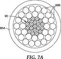
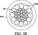
一般に、本発明によるケーブルを、コアの上でワイヤを撚り合せることによって製造することができる。コアは、たとえば、1つのワイヤ、または撚り合された(たとえば、螺旋状に巻かれたワイヤを含むことができる。いくつかの実施形態において、たとえば、7、19、または37のワイヤ。本発明によるケーブルを製造するための例示的な装置80が、図7、図7A、および図7Bに示されている。コア材料のスプール81が、従来の遊星歯車式撚り合せ機械80のヘッドに設けられ、スプール81は、自由に回転することができ、張力を制動システムによって加えることができ、張力を、(いくつかの実施形態では、0〜91kg(0〜200lb.)の範囲内で)繰出しの間コアに加えることができる。コア90は、ボビンキャリッジ82、83を通して、閉じダイ84、85を通して、キャプスタンホイール86の周りにかけられ、巻取りスプール87に取付けられる。
In general, the cable according to the invention can be produced by twisting wires on a core. The core can include, for example, one wire, or a twisted (eg, spirally wound wire. In some embodiments, for example, 7, 19, or 37 wires. The present invention. An
外側撚り合せ層の付与前、個別のワイヤが、別個のボビン88上に提供され、これらは、撚り合せ設備のいくつかのモータ駆動キャリッジ82、83内に配置される。いくつかの実施形態において、ボビン88からワイヤ89A、89Bを引くのに必要な張力の範囲は、典型的には4.5〜22.7kg(10〜50lb.)である。典型的には、完成された撚り合されたケーブルの層ごとに1つのキャリッジがある。各層のワイヤ89A、89Bは、各キャリッジの出口で閉じダイ84、85で一緒にされ、中心ワイヤの上に、または前の層の上に配列される。層は、外側層がZ撚り(right hand lay)をもたらすように両方向に螺旋状に撚り合される。ケーブル撚り合せプロセスの間、中心ワイヤ、または1つ以上の付加的な層が周りに巻かれる中間の未完成の撚り合されたケーブルは、さまざまなキャリッジの中心を通して引かれ、各キャリッジは、1つの層を撚り合されたケーブルに加える。1つの層として加えられるべき個別のワイヤは、モータ駆動キャリッジによってケーブルの中心軸の周りに回転される間、それらのそれぞれのボビンから同時に引かれる。これは、所望の層ごとに順次行われる。結果は、形状の損失もほどけることもなく好都合に切断し取扱うことができる、螺旋状に撚り合されたケーブル91である。
Prior to application of the outer twist layer, individual wires are provided on separate bobbins 88, which are placed in several motor driven
撚り合されたケーブルを取扱うこの能力は、望ましい特徴である。理論に縛られることを望まないが、ケーブルは、その螺旋状に撚り合された配列を維持し、というのは、製造の間、金属ワイヤが、ワイヤ材料の降伏応力を超えるが最終応力または破壊応力より低い、曲げ応力を含む応力を受けるからである。この応力は、ワイヤが、前の層または中心ワイヤの比較的小さい半径の周りに螺旋状に巻かれるときに与えられる。付加的な応力が閉じダイ84、85で与えられ、これらは、製造の間、半径方向の剪断力をケーブルに加える。したがって、ワイヤは、塑性変形し、それらの螺旋状に撚り合された形状を維持する。 This ability to handle twisted cables is a desirable feature. Without wishing to be bound by theory, the cable maintains its helically twisted arrangement, because during manufacture, the metal wire exceeds the yield stress of the wire material, but the final stress or failure It is because it receives stress including bending stress which is lower than stress. This stress is applied when the wire is spirally wound around a relatively small radius of the previous layer or center wire. Additional stress is provided by the closing dies 84, 85, which apply radial shear forces to the cable during manufacturing. Thus, the wires are plastically deformed and maintain their helically twisted shape.
コア材料、および所与の層のワイヤは、閉じダイによって密接に接触される。図7Aおよび図7Bを参照すると、閉じダイ84A、85Aは、典型的には、巻かれている層のワイヤ上の変形応力を最小にするようなサイズである。閉じダイの内径は、外部層直径のサイズに合される。層のワイヤ上の応力を最小にするために、閉じダイは、ケーブルの外径に対して、0〜2.0%大きい範囲内であるようなサイズである。(すなわち、ダイ内径は、ケーブル外径の1.00から1.02倍の範囲内である)。図7Aおよび図7Bに示された例示的な閉じダイは、円筒であり、たとえば、ボルトまたは他の適切な付属品を使用して、所定位置に保持される。ダイは、たとえば、硬化工具鋼から製造することができる。 The core material and the wire of a given layer are in intimate contact by a closing die. Referring to FIGS. 7A and 7B, the closing dies 84A, 85A are typically sized to minimize the deformation stress on the wire of the wound layer. The inner diameter of the closing die is matched to the size of the outer layer diameter. In order to minimize the stress on the wire of the layer, the closing die is sized to be in the range of 0-2.0% greater than the cable outer diameter. (That is, the die inner diameter is in the range of 1.00 to 1.02 times the cable outer diameter). The exemplary closing die shown in FIGS. 7A and 7B is a cylinder and is held in place using, for example, bolts or other suitable accessories. The die can be manufactured, for example, from hardened tool steel.
結果として生じる完成されたケーブルは、望ましい場合、他の撚り合せステーションを通過し、最終的に、ケーブル損傷を回避するために、十分な直径の巻取りスプール87上に巻くことができる。いくつかの実施形態において、ケーブルのくせを取るための当該技術において知られている技術が望ましいであろう。たとえば、完成されたケーブルは、ローラから構成されるくせ取り機デバイスを通過させることができる(各ローラは、たとえば、10〜15cm(4〜6インチ)、2つのバンク内に線状に配列され、たとえば、各バンク内に5〜9のローラがある。ローラの2つのバンクの間の距離は、ローラが、ケーブルに衝突するだけか、ケーブルの激しい曲げを引起すように変えることができる。ローラの2つのバンクは、ケーブルの両側に位置決めされ、一方のバンク内のローラが、他方のバンク内の対向するローラによって作られた空間と一致する。したがって、2つのバンクを互いにずらすことができる。ケーブルがくせ取りデバイスを通過するとき、ケーブルは、ローラの上で前後に曲がり、導体内のストランドが同じ長さまで伸張することを可能にし、それにより、弛んだストランドを低減するかなくす。
The resulting completed cable can be passed through other twisting stations, if desired, and finally wound on a winding
いくつかの実施形態において、ゼロ未満の応力パラメータを有するケーブルを提供するのを促進するために、周囲温度(たとえば、22℃)より高い高温(たとえば、少なくとも25℃、50℃、75℃、100℃、125℃、150℃、200℃、250℃、300℃、400℃、またはさらには、いくつかの実施形態において、少なくとも500℃)でコアを提供することが望ましい。たとえば、スプールに巻かれたコア(たとえば、金属(たとえば、鋼)上のコアをオーブン内で数時間加熱することによって、コアを所望の温度にすることができる。加熱されたスプールに巻かれたコアは、撚り合せ機械の繰出しスプール(たとえば、図7の繰出しスプール81を参照のこと)上に配置される。望ましくは、高温におけるスプールは、撚り合せプロセス中であり、コアは、依然として、所望の温度またはその近くである(典型的には約2時間以内)。さらに、ケーブルの外側層を形成する繰出しスプール上のワイヤが周囲温度であることが望ましいであろう。すなわち、撚り合せプロセスの間、コアと外側層を形成するワイヤとの間の温度差を有することが望ましい。
In some embodiments, a high temperature (eg, at least 25 ° C., 50 ° C., 75 ° C., 100 ° C.) above ambient temperature (eg, 22 ° C.) to facilitate providing a cable with a stress parameter of less than zero It is desirable to provide the core at a temperature of 125 ° C, 125 ° C, 150 ° C, 200 ° C, 250 ° C, 300 ° C, 400 ° C, or even at least 500 ° C in some embodiments. For example, the core can be brought to the desired temperature by heating the core on a spool (eg, a metal (eg, steel) in an oven for several hours in an oven. The core is placed on the payout spool of the twisting machine (see, for example,
いくつかの実施形態において、少なくとも100kg、200kg、500kg、1000kg、またはさらには少なくとも5000kgのコア張力で撚り合せを行うことが望ましいであろう。 In some embodiments, it may be desirable to twist with a core tension of at least 100 kg, 200 kg, 500 kg, 1000 kg, or even at least 5000 kg.
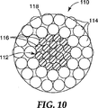
本発明によるケーブルのいくつかの実施形態(たとえば、ゼロ未満の応力パラメータを有するケーブル)において、たとえば、テープオーバラップで、接着剤でまたは接着剤なしで、またはバインダーで、コアの周りに撚り合されたワイヤをともに保持することが望ましい。たとえば、本発明による別の例示的なケーブル110の断面図が、図10に示されている。ケーブル110は、ワイヤコア116を有するコア112と、撚り合されたワイヤ114の2つの層とを含み、ケーブル110は、テープ118が巻付けられる。撚り合されたワイヤをともに保持するのを助けるために、たとえばテープを、結果として生じる撚り合されたケーブルに付与することができる。いくつかの実施形態において、ケーブルは、従来のテーピング設備を使用して、接着テープが巻付けられる。テープを付与するための1つの例示的な機械が、ワトソン・マシン・インターナショナルから市販されている(たとえば、モデル300コンセントリック・テーピング・ヘッド)。例示的なテープとしては、金属箔テープ(たとえば、アルミニウム箔テープ(たとえば、ミネソタ州セントポールの3Mカンパニーから、商品名「フォイル/ガラス・クロス・テープ363」で入手可能))、ポリエステル支持テープ、およびガラス強化バッキングを有するテープが挙げられる。いくつかの実施形態において、テープは、0.05mmから0.13mm(0.002から0.005インチ)の範囲内の厚さを有する。
In some embodiments of a cable according to the invention (eg a cable with a stress parameter of less than zero), for example with a tape overlap, with or without adhesive, or with a binder, twisted around the core It is desirable to hold the wire together. For example, a cross-sectional view of another
いくつかの実施形態において、テープは、各連続ラップが前のラップに重なるように巻付けられる。いくつかの実施形態において、テープは、各連続ラップが、間隙なしで、かつ重なりなしで、前のラップに接するように巻付けられる。いくつかの実施形態において、たとえば、テープは、連続ラップが、各ラップの間の間隙を残すように隔置されるように巻付けることができる。 In some embodiments, the tape is wound so that each successive wrap overlaps the previous wrap. In some embodiments, the tape is wound such that each continuous wrap touches the previous wrap without gaps and without overlap. In some embodiments, for example, the tape can be wound such that successive wraps are spaced apart leaving a gap between each wrap.
いくつかの実施形態において、ケーブルは、撚り合せプロセスの間ケーブルが張力下である間巻付けられる。たとえば図7を参照すると、テーピング設備が最終閉じダイ85と最終キャプスタン86との間に配置される。
In some embodiments, the cable is wound while the cable is under tension during the twisting process. For example, referring to FIG. 7, a taping facility is disposed between the final closing die 85 and the
弛みを測定するための方法
ある長さの導体を、長さ30〜300メートルに選択し、従来のエポキシ取付物で終端させ、層が、製造されたままの状態と同じ相対位置を実質的に維持することを確実にする。外側ワイヤは、エポキシ取付物を通して、他方の側から延在させ、次に、従来のターミナルコネクタを使用するAC電源への接続を考慮するように再構成する。エポキシ取付物を、張力を保持するためのターンバックルに接続されたアルミニウムスペルターソケット内に注ぐ。1つの側で、ロードセルをターンバックルに接続し、次に、両端で、ターンバックルをプリングアイに取付ける。アイを、張力下のときのシステムの端部撓みを最小にするのに十分大きい、大きいコンクリート柱に接続した。テストのため、張力を、導体定格破断強度の10から30パーセント範囲内の値に引く。温度は、導体の長さに沿った3つの位置で(総(プリングアイからプリングアイ)スパンの距離の1/4、1/2、および3/4で)、9の熱電対を使用して測定する。各位置において、3つの熱電対を、導体内の3つの異なった半径方向の位置、すなわち、外側ワイヤストランド間、内側ワイヤストランド間、および外側コアワイヤに隣接して(すなわち、接触する)位置決めする。弛み値は、導体の長さに沿った3つの位置で(スパンの距離の1/4、1/2、および3/4で)、プルワイヤポテンショメータ(カリフォルニア州パームデールのスペースエージ・コントロール・インコーポレイテッド(SpaceAge Control, Inc, Palmdale, CA)から入手可能)を使用して測定する。これらは、3つの位置の垂直移動を測定するように位置決めする。AC電流を導体に与えて、温度を所望の値に上昇させる。導体の温度は、室温(約20℃(68°F))から約240℃(464°F)に60〜120℃/分(140〜248°F/分)の範囲内の速度で上昇させる。熱電対のすべての最も高い温度を対照として用いる。
Method for Measuring Looseness A length of conductor is selected to be 30-300 meters in length and terminated with a conventional epoxy fitting so that the layer is substantially in the same relative position as it is as manufactured. Make sure to maintain. The outer wire extends from the other side through the epoxy fitting and is then reconfigured to allow for connection to an AC power source using a conventional terminal connector. The epoxy fitting is poured into an aluminum speller socket connected to a turnbuckle to maintain tension. On one side, connect the load cell to the turnbuckle and then attach the turnbuckle to the pulling eye at both ends. The eye was connected to a large concrete column large enough to minimize the end deflection of the system when under tension. For testing purposes, the tension is pulled to a value in the range of 10 to 30 percent of the conductor rated breaking strength. The temperature is 9 positions at three locations along the length of the conductor (1/4, 1/2, and 3/4 of the total (pull eye to pull eye) span distance) using 9 thermocouples. taking measurement. At each location, three thermocouples are positioned in three different radial locations within the conductor, ie, between the outer wire strands, between the inner wire strands, and adjacent to (ie, in contact with) the outer core wire. The slack values are measured at three positions along the conductor length (at 1/4, 1/2, and 3/4 of the span distance) and a pull wire potentiometer (Space Age Control Inc., Palmdale, Calif.). (Available from SpaceAge Control, Inc, Palmdale, Calif.). These are positioned to measure the vertical movement of the three positions. An AC current is applied to the conductor to raise the temperature to the desired value. The temperature of the conductor is increased from room temperature (about 20 ° C. (68 ° F.)) to about 240 ° C. (464 ° F.) at a rate in the range of 60-120 ° C./min (140-248 ° F./min). All the highest temperatures of the thermocouple are used as controls.
導体の弛み値(弛み合計)は、室温(約20℃(68°F))から約240℃(464°F)まで1度間隔でさまざまな温度で、次の式を用いて計算する。

弛み1/2=導体のスパンの距離の1/2で測定された弛み
弛み1/4=導体のスパンの距離の1/4で測定された弛み
弛み3/4=導体のスパンの距離の3/4で測定された弛み
The slack value ( total slack) of the conductor is calculated using the following equation at various temperatures at 1 degree intervals from room temperature (about 20 ° C. (68 ° F.)) to about 240 ° C. (464 ° F.).
Slack 1/2 = slack slack measured at 1/2 of the conductor span distance 1/4 = slack slack measured at 1/4 of the conductor span distance 3/4 = 3 of the conductor span distance Slack measured at / 4
有効「内側スパン」長さは、1/4の位置と3/4の位置との間の水平距離である。これは、弛みを計算するために用いられるスパン長さである。 The effective “inside span” length is the horizontal distance between the 1/4 position and the 3/4 position. This is the span length used to calculate the slack.
応力パラメータの導出
測定された弛みおよび温度データを、弛み対温度のグラフとしてプロットする。計算された曲線を、サウスカロライナ州グリーンビルのアルコア・フジクラ・リミテッド(Alcoa Fujikura Ltd., Greenville, SC)から商品名「サグ10(SAG10)」(バージョン3.0 アップデート3.9.7)でソフトウェアプログラムで入手可能なアルコア・サグ10(Alcoa Sag10)グラフィック方法を用いて、測定されたデータに適合させる。応力パラメータは、「組込みアルミニウム応力」と呼ばれる「サグ10」の適合パラメータであり、これは、アルミニウム以外の材料が使用される(たとえば、アルミニウム合金)場合、他のパラメータに適合するように変更することができ、かつ、予測されたグラフ上のニーポイントの位置、およびまた高温ポストニーポイント領域の弛みの量を調整する。応力パラメータ理論の説明が、アルコア・サグ10ユーザズマニュアル(Users Manual)(バージョン2.0):ACSRのアルミニウムの圧縮応力の理論(Theory of Compressive Stress in Aluminum of ACSR)に提供されている。次の導体パラメータが、サグ10ソフトウェア(Sag10 Software)へのエントリに必要である;面積、直径、単位長さあたりの重量、および定格破断強度。次のラインローディング条件が、サグ10ソフトウェアへのエントリに必要である;スパン長さ、室温(20〜25℃)における初期張力。次のパラメータが、圧縮応力計算を行うために、サグ10ソフトウェアへのエントリに必要である;組込みワイヤ応力、ワイヤ面積(総面積の一部として)、導体内のワイヤ層の数、導体内のワイヤストランドの数、コアストランドの数、各ワイヤ層の撚り込み率(stranding lay ratios)。応力−歪み係数が、表(下記表1を参照のこと)として、「サグ10」ソフトウェアへの入力に必要である。
Derivation of stress parameters The measured slack and temperature data is plotted as a graph of slack versus temperature. The calculated curve was obtained from Alcoa Fujikura Ltd., Greenville, SC under the trade name “SAG10” (version 3.0 update 3.9.7). The measured data is fitted using the
応力歪み曲線多項式の定義
最初の5の数字A0〜A4は、初期ワイヤ曲線×面積比を表す4次多項式の係数であり、
B0〜B4は、ワイヤの最終10年クリープ曲線×面積比を表す4次多項式の係数であり、
C0〜C4は、複合コアのみの、初期曲線×面積比を表す4次多項式の係数である。
CFは、複合コアの最終モジュラスであり、
D0〜D4は、複合コアの最終10年クリープ曲線×面積比を表す4次多項式の係数であり、
α(コア)は、複合コアの熱膨張の係数である。
Definition of Stress Strain Curve Polynomial The first five numbers A0 to A4 are coefficients of a quartic polynomial representing the initial wire curve × area ratio,
B0 to B4 are coefficients of a fourth-order polynomial representing the final 10-year creep curve of wire x area ratio,
C0 to C4 are coefficients of a quartic polynomial representing the initial curve × area ratio of the composite core only.
CF is the final modulus of the composite core,
D0 to D4 are coefficients of a fourth-order polynomial representing the final 10-year creep curve × area ratio of the composite core,
α (core) is a coefficient of thermal expansion of the composite core.
計算されたデータおよび測定されたデータを適合させる際に、最良適合は、(i)曲線が高温(140〜240℃)で一致するように応力パラメータの値を変えることによって、計算された曲線を測定されたデータに一致させ、(ii)測定された曲線の変曲点(ニーポイント)は、計算された曲線と厳密に一致し、(iii)初期の計算された弛みは、初期の測定された弛みと一致する必要がある(すなわち、24℃(75°F)における初期張力は1432kgであり、12.5cm(5インチ)の弛みを生じさせる。)。測定されたデータへの最良適合を得るための応力パラメータの値は、こうして得られる。この結果は、ケーブルの「応力パラメータ」である。 In fitting the calculated and measured data, the best fit is: (i) changing the value of the stress parameter so that the curve matches at high temperature (140-240 ° C.) Match the measured data; (ii) the inflection point (knee point) of the measured curve exactly matches the calculated curve; and (iii) the initial calculated slack is the initial measured (Ie, the initial tension at 24 ° C. (75 ° F.) is 1432 kg, producing a slack of 12.5 cm (5 inches)). The value of the stress parameter for obtaining the best fit to the measured data is thus obtained. The result is a “stress parameter” for the cable.
本発明によるケーブルを、架空送電ケーブルを含むさまざまな用途で使用することができる。 The cable according to the present invention can be used in various applications including overhead power transmission cables.
本発明の利点および実施形態を、次の実施例によって、さらに例示するが、これらの実施例に記載された特定の材料およびそれらの量、ならびに他の条件および詳細は、本発明を不当に限定するように解釈されるべきではない。部およびパーセンテージはすべて、特に明記しない限り、重量による。 The advantages and embodiments of the present invention are further illustrated by the following examples, but the specific materials and their amounts described in these examples, as well as other conditions and details, unduly limit the present invention. Should not be interpreted as. All parts and percentages are by weight unless otherwise specified.
例示的な実施例
例示的な実施例のケーブルのワイヤを次のように準備した。ワイヤを、図6に示された装置60を使用して製造した。10,000デニールのアルファアルミナ繊維(セントポールの3Mカンパニーによって、商品名「ネクステル610」で販売された)の11(11)のトウが、供給スプール62から供給され、平行にされて円形束にされ、305cm/分(120in./分)で1100℃に加熱された長さ1.5m(5ft.)のアルミナチューブ63を通過させることによってヒートクリーニングされた。次に、繊維のヒートクリーニングされた繊維61は、真空チャンバ64内で排気され、金属アルミニウム(99.99%Al)マトリックス材料(ペンシルバニア州ピッツバーグのベック・アルミニウム・カンパニー(Beck Aluminum Co., Pittsburgh, PA)から得られた)の溶融物(溶融金属)65を収容するるつぼ67に入った。繊維は、ケータプラー70によって供給スプール62から引かれた。超音波プローブ66が、溶融物65を繊維のトウ61内に浸透させるのを助けるために、溶融物65中に繊維の近傍に位置決めされた。ワイヤ71の溶融金属は、出口ダイ68を通って、るつぼ67を出た後、冷却し凝固したが、いくらかの冷却が、ワイヤ71がるつぼ67を完全に出る前におそらく発生した。さらに、ワイヤ71の冷却は、ワイヤ71に衝突した、冷却デバイス69を通って送出された窒素気体の流れによって向上された。ワイヤ71は、スプール72上に集められた。
Illustrative Example The cable of the illustrative example cable was prepared as follows. The wire was manufactured using the
繊維61は、溶融物67に入る前に排気された。真空チャンバ内の圧力は約20トルであった。真空システム64は、繊維の束61の直径と一致するサイズの、長さ25cmのアルミナ入口チューブを有した。真空チャンバ64は、長さ21cm、直径10cmであった。真空ポンプの容量は0.37m3/分であった。排気された繊維61は、金属浴に貫入した真空システム64上のチューブを通して、溶融物65に挿入された(すなわち、排気された繊維61は、溶融物54に導入されるとき真空下であった)。出口チューブの内径は、繊維束61の直径と一致した。出口チューブの一部が、溶融金属中に5cmの深さまで浸漬された。
The
溶融金属65の、繊維61内への浸透は、繊維61に密に近接するように溶融金属65中に位置決めされた振動ホーン66の使用によって向上された。ホーン66は、駆動されて、19.7kHz、および0.18mm(0.007in.)の空気の振幅で振動した。ホーンは、チタン導波管に接続され、これは、超音波トランスデューサ(コネチカット州ダンベリーのソニックス&マテリアルズから得られた)に接続された。
The penetration of the molten metal 65 into the
繊維61は、ホーン先端の2.5mm以内であった。ホーン先端は、組成91重量%Nb−9重量%Moのニオブ合金(ペンシルバニア州ピッツバーグのPMTIから得られた)から製造された。合金は、長さ12.7cm(5in.)および直径2.5cm(1in.)の円筒に作られた。円筒は、その長さを変更することによって、19.7kHzの所望の振動周波数に調整された。
The
溶融金属65は、浸透前に脱気された(たとえば、溶融金属に溶解した気体(たとえば、水素)の量を低減する)。イリノイ州シカゴのブルムンド・ファウンドリ・インコーポレイテッド(Brummund Foundry Inc, Chicago, IL)から入手可能な携帯用回転脱気ユニットが使用された。使用された気体はアルゴンであり、アルゴン流量は1分あたり1050リットルであり、速度は、1分あたり50リットルに設定されたモータへの空気流量によって提供され、持続時間は60分であった。 The molten metal 65 was degassed before infiltration (eg, reducing the amount of gas (eg, hydrogen) dissolved in the molten metal). A portable rotary degassing unit available from Brummund Foundry Inc, Chicago, IL, Chicago, Illinois was used. The gas used was argon, the argon flow rate was 1050 liters per minute, the speed was provided by the air flow rate to the motor set at 50 liters per minute, and the duration was 60 minutes.
窒化ケイ素出口ダイ68は、所望のワイヤ直径を提供するように構成された。出口ダイの内径は2.67mm(0.105in.)であった。 The silicon nitride exit die 68 was configured to provide the desired wire diameter. The inner diameter of the exit die was 2.67 mm (0.105 in.).
撚り合されたコアは、カナダ、モントリオールのワイヤ・ロープ・カンパニー(Wire Rope Company in Montreal, Canada)における撚り合せ設備上で撚り合された。ケーブルは、中心の1つのワイヤと、Z撚りでの第1の層の6のワイヤとを有した。ともに螺旋状に巻かれる前、個別のワイヤが、別個のボビン上に提供され、これらは、次に、撚り合せ設備のモータ駆動キャリッジ内に配置された。キャリッジは、完成された撚り合されたケーブルの層のための6のボビンを保持した。層のワイヤは、キャリッジの出口で一緒にされ、中心ワイヤの上に配列された。ケーブル撚り合せプロセスの間、中心ワイヤは、キャリッジの中心を通して引かれ、キャリッジは、1つの層を撚り合されたケーブルに加えた。1つの層として加えられた個別のワイヤは、モータ駆動キャリッジによってケーブルの中心軸の周りに回転される間、それらのそれぞれのボビンから同時に引かれた。結果は、螺旋状に撚り合されたコアであった。 The twisted cores were twisted on a twisting facility at Wire Rope Company in Montreal, Canada. The cable had one wire in the center and six wires of the first layer with Z twist. Prior to being helically wound together, separate wires were provided on separate bobbins, which were then placed in the motor drive carriage of the twisting facility. The carriage held 6 bobbins for the finished twisted cable layer. The layers of wire were brought together at the exit of the carriage and arranged over the center wire. During the cable twisting process, the center wire was pulled through the center of the carriage and the carriage added one layer to the twisted cable. The individual wires added as one layer were pulled simultaneously from their respective bobbins while being rotated about the central axis of the cable by the motor driven carriage. The result was a spirally twisted core.
撚り合されたコアは、従来のテーピング設備(ニュージャージー州パターソンのワトソン・マシン・インターナショナル(Watson Machine International, Paterson, NJ)からのモデル300コンセントリック・テーピング・ヘッド(Concentric Taping Head))を使用して、接着テープが巻付けられた。テープバッキングは、ガラス繊維を有するアルミニウム箔テープであり、感圧シリコーン接着剤を有した(ミネソタ州セントポールの3Mカンパニーから、商品名「フォイル/ガラス・クロス・テープ363」で得られた)。テープ18の総厚さは0.0072インチ(0.18mm)であった。テープは幅0.75インチ(1.90cm)であった。 The twisted core uses conventional taping equipment (Model 300 Concentric Taping Head from Watson Machine International, Paterson, NJ). Adhesive tape was wound. The tape backing was an aluminum foil tape with glass fibers and had a pressure sensitive silicone adhesive (obtained from 3M Company of St. Paul, Minnesota under the trade name “Foil / Glass Cloth Tape 363”). The total thickness of tape 18 was 0.0072 inches (0.18 mm). The tape was 0.75 inches (1.90 cm) wide.
完成されたコアの平均直径は0.324インチ(8.23mm)であり、撚り合された層の撚り長さは21.3インチ(54.1cm)であった。 The finished core had an average diameter of 0.324 inches (8.23 mm) and the twisted layer had a twist length of 21.3 inches (54.1 cm).
第1の台形アルミニウム合金ワイヤは、アルミニウム/ジルコニウムロッドから準備された(9.53mm(0.375インチ)の直径;ラミフィルN・V(Lamifil N.V.)(ベルギー、ヘミクセム(Hemiksem, Belguim)、商品名「ZTAL」で)から得られ、153.95MPa(22,183psi)の引張強度、13.3%の伸び、および60.4%のIACSの導電性を有した。第2の台形ワイヤは、132.32MPa(19,191psi))の引張強度、10.4%の伸び、および60.5%のIACSの導電性を有する、直径9.53mm(0.375インチ)のアルミニウム/ジルコニウムロッド(「ZTAL」)から準備された。ロッドは、室温で、当該技術において知られているように5の中間ダイを使用して、最後に台形形成ダイを使用してドローダウンされた。ドローダイは、炭化タングステンから製造された。炭化タングステンダイのジオメトリは、60°の入口角度、16〜18°の低減角度、ダイ直径の30%のベアリング長さ(a bearing length 30% of the die diameter)、および60°のバックレリーフ角度(back relief angle)を有した。ダイ表面は高度に研磨された。ダイは、ドローオイルを使用して潤滑され冷却された。ドローシステムは、1ダイあたり1分あたり60〜100リットルの範囲内に設定された速度でオイルを送出し、温度は40〜50℃の範囲内に設定された。最後の形成ダイは、高度に研磨された加工表面を有する2つの水平硬化鋼(60RC硬度)形成ロールを含んだ。ロール溝の設計は、必要な台形プロファイルに基いた。ロールは、ドローボックスと外側ドローブロックとの間に配置されたローリングスタンド上に設置された。最終形成ロール低減は、ワイヤの面積を約23.5%低減した。面積低減の量は、金属をロール溝のコーナ内に移動させ、形成ロール間の空間を適切に充填するのに十分であった。形成ロールは、台形ワイヤのキャップが、ドローブロックおよびボビンドラムの表面に面するように整列され設置された。形成後、ワイヤプロファイルは、テンプレートを使用してチェックされ確認された。
The first trapezoidal aluminum alloy wire was prepared from an aluminum / zirconium rod (9.53 mm (0.375 inch) diameter; Lamifil NV) (Hemixsem, Belgium) With a tensile strength of 153.95 MPa (22,183 psi), an elongation of 13.3%, and an electrical conductivity of IACS of 60.4%. Is a 9.75 mm (0.375 inch) diameter aluminum / zirconium rod having a tensile strength of 132.32 MPa (19,191 psi)), an elongation of 10.4%, and a conductivity of 60.5% IACS. ("ZTAL"). The rod was drawn down at room temperature using 5 intermediate dies as is known in the art and finally using a trapezoidal die. The draw die was manufactured from tungsten carbide. The geometry of the tungsten carbide die consists of a 60 ° inlet angle, a 16-18 ° reduction angle, a
次に、このワイヤはボビン上に巻かれた。結果として生じるワイヤのさまざまな特性は、下記表2に記載されている。台形形状の「有効直径」は、台形形状の断面積と同じ面積を有する円の直径を指す。撚り合せ設備内に装填された20のボビンがあり(第1の内側層を撚り合せるための第1のワイヤの8)、第2の外側層を撚り合せるための第2のワイヤの12)、ワイヤは、テストのためにこれらのサブセットからとられ、これらは「サンプルボビン」であった。 The wire was then wound on a bobbin. The various properties of the resulting wire are listed in Table 2 below. The trapezoidal “effective diameter” refers to the diameter of a circle having the same area as the cross-sectional area of the trapezoidal shape. There are 20 bobbins loaded in the twisting facility (8 of the first wire for twisting the first inner layer) and 12 of the second wire for twisting the second outer layer), Wires were taken from these subsets for testing and these were “sample bobbins”.
ケーブルが、従来の遊星歯車式撚り合せ機械、ならびに比較例について上で説明されたコアおよび(内側および外側)ワイヤを使用して、SK、ウェイバーンのネクサンズ(Nexans, Weyburn, SK)によって製造された。ケーブルを製造するための装置80の概略図が、図7、図7A、および図7Bに示されている。
The cable is manufactured by SK, Weyburn's Sands (Nexans, Weyburn, SK) using a conventional planetary gear twisting machine and the core and (inner and outer) wires described above for comparative examples. It was. A schematic diagram of an
コアのスプール81が、従来の遊星歯車式撚り合せ機械80のヘッドに設けられ、スプール81は、自由に回転することができ、張力を制動システムによって加えることができた。繰出しの間コアに加えられた張力は45kg(100lb.)であった。コアは室温(約23℃(73°F))で入力された。コアは、ボビンキャリッジ82、83の中心を通して、閉じダイ84、85を通して、キャプスタンホイール86の周りにかけられ、従来の巻取り(152cm(60in.)の直径)スプール87に取付けられた。
A
外側撚り合せ層の付与前、個別のワイヤが、別個のボビン88上に提供され、これらは、撚り合せ設備のいくつかのモータ駆動キャリッジ82、83内に配置された。ボビン88からワイヤ89を引くのに必要な張力の範囲は、11〜14kg(25〜30lb.)の範囲内であるように設定された。撚り合せステーションは、キャリッジと、閉じダイとからなる。各撚り合せステーションにおいて、各層のワイヤ89は、各キャリッジの出口で、それぞれ、閉じダイ84、85で一緒にされ、それぞれ、中心ワイヤの上に、または前の層の上に配列された。したがって、コアは、2つの撚り合せステーションを通過した。第1のステーションにおいて、8のワイヤを、コアの上でS撚り(left lay)で撚り合せた。第2のステーションにおいて、12のワイヤを、前の層の上でZ撚り(right lay)で撚り合せた。
Prior to the application of the outer twist layer, individual wires were provided on separate bobbins 88, which were placed in several motor driven
コア材料、および所与の層のワイヤは、適用できるような閉じダイ84、85によって接触された。閉じダイは、円筒(図7Aおよび図7Bを参照のこと)であり、ボルトを使用して所定位置に保持された。ダイは、硬化工具鋼から製造され、完全に閉じることができた。
The core material and the wire of a given layer were contacted by a
完成されたケーブルは、キャプスタンホイール86を通過され、最終的に、(91cmの直径(36インチ))巻取りスプール87上に巻かれた。完成されたケーブルは、各バンク内に7のローラで、2つのバンク内に線状に配列されたローラ(各ローラは12.5cm(5インチ)である)から構成されたくせ取り機デバイスを通過された。ローラの2つのバンクの間の距離は、ローラがケーブルに衝突するだけであるように設定された。ローラの2つのバンクは、ケーブルの両側に位置決めされ、一方のバンク内のローラが、他方のバンク内の対向するローラによって作られた空間と一致した。したがって、2つのバンクは互いにずれた。ケーブルがくせ取りデバイスを通過するとき、ケーブルは、ローラの上で前後に曲がり、導体内のストランドが同じ長さまで伸張することを可能にし、それにより、弛んだストランドをなくした。
The finished cable was passed through the
内側層は、15.4mm(0.608in.)の外側層直径、353kg/km(237lb./kft.)の単位長さあたり質量で、20.3cm(8in.)のS撚り(left hand lay)で、8の台形ワイヤからなった。内側層のための閉じブロック(硬化工具鋼から製造された;60Rc硬度)は、15.4mm(0.608in.)の内径に設定された。したがって、閉じブロックは、ケーブル直径とちょうど同じ直径に設定された。 The inner layer has an outer layer diameter of 15.4 mm (0.608 in.), A mass per unit length of 353 kg / km (237 lb./kft.), And a left hand lay of 20.3 cm (8 in.). ) And consisted of 8 trapezoidal wires. The closed block for the inner layer (manufactured from hardened tool steel; 60 Rc hardness) was set to an inner diameter of 15.4 mm (0.608 in.). Therefore, the closing block was set to exactly the same diameter as the cable diameter.
外側層は、22.9mm(0.9015in.)の外側層直径、507.6kg/km(341.2lb./kft)の単位長さあたり質量で、25.9cm(10.2in.)のZ撚りで、12の台形ワイヤからなった。アルミニウム合金ワイヤの単位長さあたり総質量は928.8kg/km(624.3lb./kft.)であり、コアの単位長さあたり総質量は136.4kg/km(91.7lb./kft.)であり、単位長さあたり総導体質量は1065kg/km(716.0lb./kft.)であった。外側層のための閉じブロック(硬化工具鋼から製造された;60Rc硬度)は、0.9015in.(22.9mm)の内径に設定された。したがって、閉じブロックは、最終ケーブル直径とちょうど同じ直径に設定された。 The outer layer has an outer layer diameter of 22.9 mm (0.9015 in.), A mass per unit length of 507.6 kg / km (341.2 lb./kft) and a Z of 25.9 cm (10.2 in.). Made of 12 trapezoidal wires with twist. The total mass per unit length of the aluminum alloy wire is 928.8 kg / km (624.3 lb./kft.), And the total mass per unit length of the core is 136.4 kg / km (91.7 lb./kft.). The total conductor mass per unit length was 1065 kg / km (716.0 lb./kft.). The closed block for the outer layer (manufactured from hardened tool steel; 60 Rc hardness) is 0.9015 in. The inner diameter was set to (22.9 mm). Therefore, the closing block was set to the same diameter as the final cable diameter.
内側ワイヤおよび外側ワイヤ張力(繰出しボビンとしての)は、ハンドヘルドフォースゲージ(入手可能な、イリノイ州シカゴのマクマスター−カード(McMaster−Card, Chicago, IL))を使用して測定され、13.5〜15kg(29〜33lb.)の範囲内であるように設定され、コア繰出し張力は、ブレーキによって、ボビンと同じ測定方法を用いて、約90kg(198lb.)に設定された。さらに、くせ取り機は使用されず、ケーブルはスプールに巻かれなかったが、まっすぐに走り、フロア上に広がる(lay out)に任された。コアは室温(約23℃(73°F))で入力された。 Inner wire and outer wire tension (as payout bobbins) were measured using a handheld force gauge (available McMaster-Card, Chicago, Ill.) (13.5). Set to be in the range of ˜15 kg (29-33 lb.), the core payout tension was set to about 90 kg (198 lb.) by the brake using the same measurement method as the bobbin. In addition, the scissor machine was not used and the cable was not wound on the spool, but it was left to run straight and lay out on the floor. The core was input at room temperature (approximately 23 ° C. (73 ° F.)).
撚り合せ機械は、15m/分(49ft/分)で動作され、従来のキャプスタンホイール、標準くせ取りデバイス、および従来の直径152cm(60in.)の巻取りスプールを使用して駆動された。 The twisting machine was operated at 15 m / min (49 ft / min) and was driven using a conventional capstan wheel, a standard combing device, and a conventional 152 cm (60 in.) Diameter take-up spool.
結果として生じる導体を、次の「切断端部テスト方法」を用いてテストした。テストされるべき導体のセクションをフロア上にまっすぐに広げ、長さ3.1〜4.6m(10〜15ft.)のサブセクションを両端で締付けた。次に、導体を切断して、依然として両端で締付けられたセクションを隔離した。次に、1つの締付けを解除し、層移動は観察されなかった。次に、導体のセクションを、層の、互いに対する移動について検査した。各層の移動を、定規を使用して測定して、コアに対する移動の量を定めた。外側アルミニウム層は複合コアに対して引っ込み、コアをゼロ基準位置とみなし、内側アルミニウム層は0.16in.(4mm)引っ込み、外側層は0.31in.(8mm)引っ込んだ。 The resulting conductor was tested using the following “Cut End Test Method”. The section of the conductor to be tested was spread straight over the floor and a subsection of length 3.1-4.6 m (10-15 ft.) Was clamped at both ends. The conductor was then cut to isolate the sections that were still clamped at both ends. Then one clamp was released and no layer transfer was observed. The conductor sections were then inspected for movement of the layers relative to each other. The movement of each layer was measured using a ruler to determine the amount of movement relative to the core. The outer aluminum layer retracts against the composite core, considering the core as the zero reference position, and the inner aluminum layer is 0.16 in. (4 mm) retracted, outer layer 0.31 in. (8mm) retracted.
例示的な実施例のケーブルを、また、カナダ、オンタリオ州トロントのキネクトリックス・インコーポレイテッド(Kinectrics, Inc. Toronto, Ontario, Canada)によって、次の「弛みテスト方法I」を用いて、評価した。ある長さの導体を従来のエポキシ取付物で終端させ、層が、製造されたままの状態と同じ相対位置を実質的に維持することを確実にし、ただし、アルミニウム/ジルコニウムワイヤを、エポキシ取付物を通して、他方の側から延在させ、次に、従来のターミナルコネクタを使用するAC電源への接続を考慮するように再構成した。エポキシ取付物を、張力を保持するためのターンバックルに接続されたアルミニウムスペルターソケット内に注いだ。1つの側で、ロードセルをターンバックルに接続し(5000キログラム(kg)のキャパシティ)、次に、両端で、ターンバックルをプリングアイに取付けた。アイを、張力下のときのシステムの端部撓みを最小にするのに十分大きい、大きいコンクリート柱に接続した。テストのため、張力を、導体定格破断強度の20%に引いた。したがって、2082kg(4590lb)をケーブルに加えた。温度は、導体の長さに沿った3つの位置で(総(プリングアイからプリングアイ)スパンの距離の1/4、1/2、および3/4で)、9の熱電対(各位置に3つ;コネチカット州スタンフォードのオメガ・コーポレーション(Omega Corporation, Stamford, CT)から入手可能なJタイプ)を使用して測定した。各位置において、3つの熱電対を、導体内の3つの異なった半径方向の位置、すなわち、外側アルミニウムストランド間、内側アルミニウムストランド間、および外側コアワイヤに隣接して(すなわち、接触する)位置決めした。弛み値は、導体の長さに沿った3つの位置で(スパンの距離の1/4、1/2、および3/4で)、プルワイヤポテンショメータ(カリフォルニア州パームデールのスペースエージ・コントロール・インコーポレイテッドから入手可能)を使用して測定した。これらは、3つの位置の垂直移動を測定するように位置決めした。AC電流を導体に与えて、温度を所望の値に上昇させた。導体の温度は、室温(約20℃(68°F))から約240℃(464°F)に60〜120℃/分(140〜248°F/分)の範囲内の速度で上昇させた。熱電対のすべての最も高い温度を対照として用いた。240℃(464°F)を達成するために、約1200ampが必要であった。 Exemplary example cables were also evaluated by Kinetics, Inc. Toronto, Ontario, Canada, Toronto, Ontario, Canada, using the following "sag test method I". A length of conductor is terminated with a conventional epoxy fixture to ensure that the layer remains substantially in the same relative position as it is manufactured, except that the aluminum / zirconium wire is bonded to the epoxy fixture. Through the other side and then reconfigured to allow for connection to an AC power source using a conventional terminal connector. The epoxy fixture was poured into an aluminum speller socket connected to a turnbuckle to maintain tension. On one side, the load cell was connected to a turnbuckle (capacity of 5000 kilograms (kg)) and then, at both ends, the turnbuckle was attached to a pulling eye. The eye was connected to a large concrete column large enough to minimize the end deflection of the system when under tension. For testing purposes, the tension was pulled to 20% of the conductor rated breaking strength. Accordingly, 2082 kg (4590 lb) was added to the cable. The temperature was measured at three locations along the length of the conductor (1/4, 1/2, and 3/4 of the total (pull-eye to pull-eye) span distance), and 9 thermocouples (at each location). 3; J type available from Omega Corporation, Stamford, Conn.). At each location, three thermocouples were positioned adjacent to (ie, in contact with) three different radial locations within the conductor: between the outer aluminum strands, between the inner aluminum strands, and the outer core wire. The slack values are measured at three positions along the conductor length (at 1/4, 1/2, and 3/4 of the span distance) and a pull wire potentiometer (Space Age Control Inc., Palmdale, Calif.). The measurement was carried out using These were positioned to measure the vertical movement of the three positions. An AC current was applied to the conductor to raise the temperature to the desired value. The temperature of the conductor was increased from room temperature (about 20 ° C. (68 ° F.)) to about 240 ° C. (464 ° F.) at a rate in the range of 60-120 ° C./min (140-248 ° F./min). . All the highest temperatures of the thermocouple were used as controls. Approximately 1200 amp was required to achieve 240 ° C (464 ° F).
導体の弛み値(弛み合計)は、さまざまな温度で、次の式を用いて計算した。
弛み1/2=導体のスパンの距離の1/2で測定された弛み
弛み1/4=導体のスパンの距離の1/4で測定された弛み
弛み3/4=導体のスパンの距離の3/4で測定された弛み
The slack value ( total slack) of the conductor was calculated using the following formula at various temperatures.
Slack 1/2 = slack slack measured at 1/2 of the conductor span distance 1/4 = slack slack measured at 1/4 of the conductor span distance 3/4 = 3 of the conductor span distance Slack measured at / 4
表3(下記)は、固定入力テストパラメータを要約する。 Table 3 (below) summarizes the fixed input test parameters.
結果として生じる弛みおよび温度データ(例示的な実施例の「結果として生じるデータ」)をプロットし、次に、計算された曲線を、サウスカロライナ州グリーンビルのアルコア・フジクラ・リミテッドから商品名「サグ10」(バージョン3.0 アップデート3.9.7)でソフトウェアプログラムで入手可能なアルコア・サグ10グラフィック方法を用いて適合させた。応力パラメータは、「組込みアルミニウム応力」と呼ばれる「サグ10」の適合パラメータであり、これは、予測されたグラフ上のニーポイントの位置、およびまた高温ポストニーポイント領域の弛みの量を調整した。応力パラメータ理論の説明が、アルコア・サグ10ユーザズマニュアル(バージョン2.0):ACSRのアルミニウムの圧縮応力の理論に提供された。示された表4〜7(下記)のような675kcmilのケーブルの導体パラメータをサグ10ソフトウェアに入力した。最良適合は、(i)曲線が高温(140〜240℃)で一致するように応力パラメータの値を変えることによって、計算された曲線を「結果として生じるデータ」に一致させ、(ii)「結果として生じるデータ」曲線の変曲点(ニーポイント)は、計算された曲線と厳密に一致し、(iii)初期の計算された弛みは、初期の「結果として生じるデータ」弛みと一致する必要があった(すなわち、22℃(72°F)における初期張力は2082kgであり、27.7cm(10.9インチ)の弛みを生じさせる。)。この実施例の場合、応力パラメータの3.5MPa(500psi)の値が、「結果として生じるデータ」への最良適合を提供した。図8は、サグ10によって計算された弛み(線82)、および測定された弛み(プロットされたデータ83)を示す。
Plot the resulting slack and temperature data ("resulting data" in the illustrative example), and then calculate the calculated curve from Alcoa Fujikura Limited, Greenville, SC under the trade name "Sag". 10 ”(version 3.0 update 3.9.7) was adapted using the
次の導体データを「サグ10」ソフトウェアに入力した。
The next conductor data was entered into the “
応力歪み曲線多項式の定義
最初の5の数字A0〜A4は、初期アルミニウム曲線×面積比を表す4次多項式の係数であり、
B0〜B4は、アルミニウムの最終10年クリープ曲線×面積比を表す4次多項式の係数であり、
C0〜C4は、複合コアのみの、初期曲線×面積比を表す4次多項式の係数である。
CFは、複合コアの最終モジュラスであり、
D0〜D4は、複合コアの最終10年クリープ曲線×面積比を表す4次多項式の係数であり、
α(コア)は、複合コアの熱膨張の係数である。
Definition of Stress Strain Curve Polynomial The first 5 numbers A0 to A4 are coefficients of a quartic polynomial representing the initial aluminum curve × area ratio,
B0 to B4 are coefficients of a fourth-order polynomial representing the final 10-year creep curve of aluminum × area ratio,
C0 to C4 are coefficients of a quartic polynomial representing the initial curve × area ratio of the composite core only.
CF is the final modulus of the composite core,
D0 to D4 are coefficients of a fourth-order polynomial representing the final 10-year creep curve × area ratio of the composite core,
α (core) is a coefficient of thermal expansion of the composite core.
予測実施例1
ケーブルを、次の通りである以外は、例示的な実施例で説明されたように製造する。コアを形成するために撚り合される複合ワイヤは、炭素繊維複合(ビスマレイックアミド(bismaleic amid)樹脂マトリックス内の炭素繊維)ワイヤからなる。これらのワイヤは、日本、東京の東京製綱株式会社(Tokyo Rope Manufacturing Company, Ltd.)から、商品名「CFCC」で入手可能である。複合ワイヤは、例示的な実施例の複合ワイヤと同じ直径を有する。
Prediction example 1
The cable is manufactured as described in the exemplary embodiment except as follows. The composite wire that is twisted together to form the core consists of a carbon fiber composite (carbon fiber in a bismaleic amide resin matrix) wire. These wires are available under the trade name “CFCC” from Tokyo Rope Manufacturing Company, Ltd., Tokyo, Japan. The composite wire has the same diameter as the composite wire of the exemplary embodiment.
例示的な実施例で説明されたアルコア・サグ10グラフィック方法モデルを用いて、予測実施例1で説明されたケーブルの弛み対温度挙動を予測した。例示的な実施例のサグ10モデルおよび方法を用いて、弛み対温度曲線を生成した。表8〜11(下記)に示された導体パラメータを、サグ10ソフトウェアに入力した。予測実施例1の圧縮応力パラメータの値は、3.5MPa(500psi)であった。さらに、55MPa(8000psi)の圧縮応力値について、弛み対温度曲線を生成した。図9は、例示的な実施例および予測実施例1の弛み対温度曲線を示す。例示的な実施例の測定されたデータは、プロットされたデータ93として示されており、例示的な実施例の計算された曲線は、線92として示されている。3.5MPa(500psi)の応力パラメータを用いた予測実施例1の計算された曲線は、線94として示されている。55MPa(8000psi)の応力パラメータでの付加的な計算された曲線は、線96として示されている。
The
次の導体データを「サグ10」ソフトウェアに入力した。
The next conductor data was entered into the “
本発明のさまざまな変更および改変が、本発明の範囲および精神から逸脱することなく、当業者には明らかになるであろう。また、本発明は、ここに記載された例示的な実施形態に不当に限定されるべきではないことが理解されるべきである。
以下に、本願発明に関連する発明の実施形態について、列挙する。
実施形態1
熱膨張係数を有し、かつ、アラミド、セラミック、ホウ素、ポリ(p−フェニレン−2,6−ベンゾビスオキサゾール)、黒鉛、炭素、チタン、タングステン、または形状記憶合金の少なくとも1つを含む長手方向のコアと、
合せて前記コアの熱膨張係数より大きい熱膨張係数を有する複数のワイヤであって、前記複数のワイヤが、アルミニウムワイヤ、銅ワイヤ、アルミニウム合金ワイヤ、または銅合金ワイヤの少なくとも1つを含み、前記複数のワイヤが、前記コアの周りに撚り合される、複数のワイヤとを
含むケーブルであって、
前記長手方向のコアが金属マトリックス複合ワイヤを含む場合、前記コアが、別個に、アラミド、セラミック、ホウ素、ポリ(p−フェニレン−2,6−ベンゾビスオキサゾール)、黒鉛、炭素、チタン、タングステン、または形状記憶合金の少なくとも1つを含むという条件で、前記ケーブルが20MPa以下の応力パラメータを有する、ケーブル。
実施形態2
前記ケーブルが15MPa以下の応力パラメータを有する、実施形態1に記載のケーブル。
実施形態3
前記ケーブルが10MPa以下の応力パラメータを有する、実施形態1に記載のケーブル。
実施形態4
前記ケーブルが5MPa以下の応力パラメータを有する、実施形態1に記載のケーブル。
実施形態5
前記ケーブルが0MPaから15MPaの範囲内の応力パラメータを有する、実施形態1に記載のケーブル。
実施形態6
前記ケーブルが0MPaから10MPaの範囲内の応力パラメータを有する、実施形態1に記載のケーブル。
実施形態7
前記コアが、ポリマーマトリックス内の、アラミド、セラミック、ホウ素、ポリ(p−フェニレン−2,6−ベンゾビスオキサゾール)、黒鉛、炭素、チタン、タングステン、または形状記憶合金の少なくとも1つの連続繊維を含む複合体を含む、実施形態1に記載のケーブル。
実施形態8
前記コアが、ポリマーマトリックス内の連続セラミックを含む複合体を含む、実施形態1に記載のケーブル。
実施形態9
前記ワイヤおよび前記コアが、連続しており、長さが少なくとも150メートルである、実施形態1に記載のケーブル。
実施形態10
前記コアが、1mmから12mmの直径を有するワイヤを含む、実施形態1に記載のケーブル。
実施形態11
前記コアが、1mmから4mmの直径を有するワイヤを含む、実施形態1に記載のケーブル。
実施形態12
前記コアのワイヤが、10から150の撚り係数を有するように螺旋状に撚り合される、実施形態1に記載のケーブル。
実施形態13
前記ワイヤが、形状が台形である、実施形態1に記載のケーブル。
実施形態14
ケーブルを製造する方法であって、
複数のワイヤを長手方向のコアの周りに撚り合せて、予備的な撚り合されたケーブルを提供する工程であって、前記複数のワイヤが、アルミニウムワイヤ、銅ワイヤ、アルミニウム合金ワイヤ、または銅合金ワイヤの少なくとも1つを含み、前記コアが、アラミド、セラミック、ホウ素、ポリ(p−フェニレン−2,6−ベンゾビスオキサゾール)、黒鉛、炭素、チタン、タングステン、または形状記憶合金の少なくとも1つを含む工程と、
前記予備的な撚り合されたケーブルを閉じダイにかけて、実施形態1に記載のケーブルを提供する工程であって、前記閉じダイが内径を有し、前記ケーブルが外径を有し、前記ダイ内径が前記ケーブル外径の1.00から1.02倍の範囲内である工程とを含む方法。
Various changes and modifications of this invention will become apparent to those skilled in the art without departing from the scope and spirit of this invention. It should also be understood that the invention should not be unduly limited to the exemplary embodiments described herein.
Below, it enumerates about the embodiment of the invention relevant to this invention.
Embodiment 1
Longitudinal direction having a thermal expansion coefficient and including at least one of aramid, ceramic, boron, poly (p-phenylene-2,6-benzobisoxazole), graphite, carbon, titanium, tungsten, or shape memory alloy Core of the
A plurality of wires having a coefficient of thermal expansion greater than that of the core, the plurality of wires including at least one of an aluminum wire, a copper wire, an aluminum alloy wire, or a copper alloy wire, A plurality of wires, wherein a plurality of wires are twisted around the core;
Including cables,
When the longitudinal core comprises a metal matrix composite wire, the core is separately aramid, ceramic, boron, poly (p-phenylene-2,6-benzobisoxazole), graphite, carbon, titanium, tungsten, Alternatively, the cable has a stress parameter of 20 MPa or less, provided that the cable includes at least one of shape memory alloys.
Embodiment 2
The cable of embodiment 1, wherein the cable has a stress parameter of 15 MPa or less.
Embodiment 3
The cable of embodiment 1, wherein the cable has a stress parameter of 10 MPa or less.
Embodiment 4
The cable of embodiment 1, wherein the cable has a stress parameter of 5 MPa or less.
Embodiment 5
The cable of embodiment 1, wherein the cable has a stress parameter in the range of 0 MPa to 15 MPa.
Embodiment 6
The cable of embodiment 1, wherein the cable has a stress parameter in the range of 0 MPa to 10 MPa.
Embodiment 7
The core includes at least one continuous fiber of aramid, ceramic, boron, poly (p-phenylene-2,6-benzobisoxazole), graphite, carbon, titanium, tungsten, or shape memory alloy in a polymer matrix. The cable of embodiment 1, comprising the composite.
Embodiment 8
The cable of embodiment 1, wherein the core comprises a composite comprising a continuous ceramic in a polymer matrix.
Embodiment 9
The cable of embodiment 1, wherein the wire and the core are continuous and have a length of at least 150 meters.
The cable of embodiment 1, wherein the core comprises a wire having a diameter of 1 mm to 12 mm.
Embodiment 11
The cable of embodiment 1, wherein the core comprises a wire having a diameter of 1 mm to 4 mm.
The cable of embodiment 1, wherein the core wires are helically twisted so as to have a twist factor of 10 to 150.
Embodiment 13
The cable of embodiment 1, wherein the wire is trapezoidal in shape.
A method of manufacturing a cable comprising:
Twisting a plurality of wires around a longitudinal core to provide a pre-twisted cable, the plurality of wires being an aluminum wire, a copper wire, an aluminum alloy wire, or a copper alloy Including at least one of wires, wherein the core comprises at least one of aramid, ceramic, boron, poly (p-phenylene-2,6-benzobisoxazole), graphite, carbon, titanium, tungsten, or shape memory alloy. Including a process;
A process of providing the cable of embodiment 1 by applying the pre-twisted cable to a closed die, wherein the closed die has an inner diameter, the cable has an outer diameter, and the die inner diameter. Is within the range of 1.00 to 1.02 times the cable outer diameter.
Claims (2)
合せて前記コアの熱膨張係数より大きい熱膨張係数を有する複数のワイヤであって、前記複数のワイヤが、アルミニウムワイヤ、銅ワイヤ、アルミニウム合金ワイヤ、または銅合金ワイヤの少なくとも1つを含み、前記複数のワイヤが、前記コアの周りに撚り合される、複数のワイヤとを
含むケーブルであって、
前記ケーブルが5MPa以下の応力パラメータを有する、ケーブル。Longitudinal direction having a thermal expansion coefficient and including at least one of aramid, ceramic, boron, poly (p-phenylene-2,6-benzobisoxazole), graphite, carbon, titanium, tungsten, or shape memory alloy Core of the
A plurality of wires having a coefficient of thermal expansion greater than that of the core, the plurality of wires including at least one of an aluminum wire, a copper wire, an aluminum alloy wire, or a copper alloy wire, A cable comprising a plurality of wires, wherein a plurality of wires are twisted around the core ,
Before Symbol cable has the following stress parameters 5MPa, cable.
Applications Claiming Priority (3)
| Application Number | Priority Date | Filing Date | Title |
|---|---|---|---|
| US10/870,262 | 2004-06-17 | ||
| US10/870,262 US7093416B2 (en) | 2004-06-17 | 2004-06-17 | Cable and method of making the same |
| PCT/US2005/013009 WO2006006997A1 (en) | 2004-06-17 | 2005-04-18 | Cable and method of making the same |
Publications (3)
| Publication Number | Publication Date |
|---|---|
| JP2008503056A JP2008503056A (en) | 2008-01-31 |
| JP2008503056A5 JP2008503056A5 (en) | 2008-06-05 |
| JP4944021B2 true JP4944021B2 (en) | 2012-05-30 |
Family
ID=34982512
Family Applications (1)
| Application Number | Title | Priority Date | Filing Date |
|---|---|---|---|
| JP2007516475A Expired - Fee Related JP4944021B2 (en) | 2004-06-17 | 2005-04-18 | Cable and manufacturing method thereof |
Country Status (10)
| Country | Link |
|---|---|
| US (1) | US7093416B2 (en) |
| EP (1) | EP1766640B1 (en) |
| JP (1) | JP4944021B2 (en) |
| KR (1) | KR101152477B1 (en) |
| CN (1) | CN100576368C (en) |
| BR (1) | BRPI0512216B1 (en) |
| CA (1) | CA2568527C (en) |
| ES (1) | ES2552694T3 (en) |
| PL (1) | PL1766640T3 (en) |
| WO (1) | WO2006006997A1 (en) |
Families Citing this family (87)
| Publication number | Priority date | Publication date | Assignee | Title |
|---|---|---|---|---|
| US7134267B1 (en) * | 2003-12-16 | 2006-11-14 | Samson Rope Technologies | Wrapped yarns for use in ropes having predetermined surface characteristics |
| US20050279526A1 (en) * | 2004-06-17 | 2005-12-22 | Johnson Douglas E | Cable and method of making the same |
| US20050279527A1 (en) * | 2004-06-17 | 2005-12-22 | Johnson Douglas E | Cable and method of making the same |
| KR100594658B1 (en) * | 2005-01-29 | 2006-06-30 | 엘에스전선 주식회사 | Fiber reinforced plastic wire for overhead trasmission cable strength member, method for manufacturing the same, and overhead transmission cable using the same |
| US8341930B1 (en) | 2005-09-15 | 2013-01-01 | Samson Rope Technologies | Rope structure with improved bending fatigue and abrasion resistance characteristics |
| JP2009522461A (en) * | 2005-12-30 | 2009-06-11 | スリーエム イノベイティブ プロパティズ カンパニー | Ceramic oxide fiber |
| FR2896911B1 (en) * | 2006-02-01 | 2008-03-21 | Nexans Sa | ELECTRICAL TRANSPORT CONDUCTOR FOR AERIAL LINE |
| US7353602B2 (en) * | 2006-03-07 | 2008-04-08 | 3M Innovative Properties Company | Installation of spliced electrical transmission cables |
| US7547843B2 (en) * | 2006-12-28 | 2009-06-16 | 3M Innovative Properties Company | Overhead electrical power transmission line |
| US7687710B2 (en) | 2006-12-28 | 2010-03-30 | 3M Innovative Properties Company | Overhead electrical power transmission line |
| US7921005B2 (en) * | 2006-12-28 | 2011-04-05 | 3M Innovative Properties Company | Method for selecting conductors of an overhead power transmission line |
| US7620517B2 (en) * | 2007-02-05 | 2009-11-17 | Abb Research Ltd. | Real-time power-line sag monitoring using time-synchronized power system measurements |
| CA2675253C (en) * | 2007-02-16 | 2016-02-23 | Nv Bekaert Sa | An improved steel core for an electric transmission cable and method of fabricating it |
| WO2008144521A1 (en) * | 2007-05-16 | 2008-11-27 | Thyssenkrupp Elevator Capital Corporation | Actively damped tension member |
| EP2034089A3 (en) * | 2007-09-10 | 2009-06-24 | Fatzer AG Drahtseilwerk | Heatable cable |
| US9034007B2 (en) | 2007-09-21 | 2015-05-19 | Insera Therapeutics, Inc. | Distal embolic protection devices with a variable thickness microguidewire and methods for their use |
| US7908955B1 (en) | 2007-10-05 | 2011-03-22 | Samson Rope Technologies | Rope structures and rope displacement systems and methods for lifting, lowering, and pulling objects |
| US8272214B2 (en) * | 2008-03-07 | 2012-09-25 | GM Global Technology Operations LLC | Shape memory alloy cables |
| KR100866313B1 (en) * | 2008-03-31 | 2008-10-31 | 주식회사 샤인 | Window screen |
| US8109071B2 (en) * | 2008-05-16 | 2012-02-07 | Samson Rope Technologies | Line structure for marine use in contaminated environments |
| US8109072B2 (en) | 2008-06-04 | 2012-02-07 | Samson Rope Technologies | Synthetic rope formed of blend fibers |
| US8525033B2 (en) * | 2008-08-15 | 2013-09-03 | 3M Innovative Properties Company | Stranded composite cable and method of making and using |
| US20100059249A1 (en) * | 2008-09-09 | 2010-03-11 | Powers Wilber F | Enhanced Strength Conductor |
| US8957312B2 (en) * | 2009-07-16 | 2015-02-17 | 3M Innovative Properties Company | Submersible composite cable and methods |
| JP5286227B2 (en) * | 2009-11-06 | 2013-09-11 | 株式会社神戸製鋼所 | Method for connecting reinforcing fiber bundles, method for producing long fiber reinforced thermoplastic resin pellets, and wound body |
| KR101813295B1 (en) | 2009-11-11 | 2017-12-28 | 보레알리스 아게 | A polymer composition and a power cable comprising the polymer composition |
| US9365708B2 (en) | 2009-11-11 | 2016-06-14 | Borealis Ag | Cable and production process thereof |
| EP2499176B2 (en) * | 2009-11-11 | 2022-08-10 | Borealis AG | Power cable comprising a polymer composition comprising a polyolefin produced in a high pressure process |
| BR112012019135A2 (en) * | 2010-02-01 | 2016-06-28 | 3M Innovative Properties Co | stranded thermoplastic polymer composite cable, method of manufacture and use thereof |
| CN102782943A (en) * | 2010-02-18 | 2012-11-14 | 3M创新有限公司 | Compression connector and assembly for composite cables and methods for making and using same |
| CN103109330B (en) | 2010-09-17 | 2016-03-09 | 3M创新有限公司 | The thermosetting polymer composite wire of fiber strengthened loading nano particle, cable and method |
| ES2508172T3 (en) | 2010-09-17 | 2014-10-16 | 3M Innovative Properties Company | Particle pultrusion processing assistants |
| EP3591670A1 (en) | 2010-11-03 | 2020-01-08 | Borealis AG | A polymer composition and a power cable comprising the polymer composition |
| US20120111603A1 (en) * | 2010-11-10 | 2012-05-10 | Jorge Cofre | Power and/or telecommunication cable comprising a reinforced ground-check conductor |
| US20120170900A1 (en) * | 2011-01-05 | 2012-07-05 | Alcan Products Corporation | Aluminum Alloy Conductor Composite Reinforced for High Voltage Overhead Power Lines |
| WO2012142096A1 (en) | 2011-04-12 | 2012-10-18 | Ticona Llc | Composite core for electrical transmission cables |
| CN103547439A (en) | 2011-04-12 | 2014-01-29 | 提克纳有限责任公司 | Die and method for impregnating fiber rovings |
| CN103547440B (en) | 2011-04-12 | 2017-03-29 | 提克纳有限责任公司 | For impregnating the mould impregnation section and method of fiber roving |
| CA2832453C (en) | 2011-04-12 | 2019-09-10 | Southwire Company | Electrical transmission cables with composite cores |
| KR20140015462A (en) | 2011-04-12 | 2014-02-06 | 티코나 엘엘씨 | Continious fiber reinforced thermoplastic rod and pultrusion method for its manufacture |
| CN103477020A (en) | 2011-04-12 | 2013-12-25 | 提克纳有限责任公司 | Umbilical for use in subsea applications |
| CA2775445C (en) | 2011-04-29 | 2019-04-09 | Ticona Llc | Die and method for impregnating fiber rovings |
| CN104053530B (en) | 2011-04-29 | 2016-10-19 | 提克纳有限责任公司 | For impregnating the mould with flowing diffusion cast path and the method for fiber roving |
| CA2775442C (en) | 2011-04-29 | 2019-01-08 | Ticona Llc | Impregnation section with upstream surface and method for impregnating fiber rovings |
| US20120297746A1 (en) * | 2011-05-24 | 2012-11-29 | Samson Rope Technologies | Rope Structures and Methods |
| WO2013016121A1 (en) | 2011-07-22 | 2013-01-31 | Ticona Llc | Extruder and method for producing high fiber density resin structures |
| US9409355B2 (en) | 2011-12-09 | 2016-08-09 | Ticona Llc | System and method for impregnating fiber rovings |
| WO2013086269A1 (en) | 2011-12-09 | 2013-06-13 | Ticona Llc | Impregnation section of die for impregnating fiber rovings |
| US9624350B2 (en) | 2011-12-09 | 2017-04-18 | Ticona Llc | Asymmetric fiber reinforced polymer tape |
| US9283708B2 (en) | 2011-12-09 | 2016-03-15 | Ticona Llc | Impregnation section for impregnating fiber rovings |
| BR112014012308A2 (en) | 2011-12-09 | 2017-06-13 | Ticona Llc | matrix impregnation section impregnate fiber wisps |
| CN103390459A (en) * | 2012-05-10 | 2013-11-13 | 河南科信电缆有限公司 | Triangular carbon fiber composite core photoelectricity composite overhead conductor |
| CN103390461A (en) * | 2012-05-10 | 2013-11-13 | 河南科信电缆有限公司 | Low-swinging carbon fiber composite core photoelectric composite overhead conductor |
| CN103390457A (en) * | 2012-05-10 | 2013-11-13 | 河南科信电缆有限公司 | Quincunx carbon fiber composite core photoelectricity composite overhead conductor |
| WO2013188644A1 (en) | 2012-06-15 | 2013-12-19 | Ticona Llc | Subsea pipe section with reinforcement layer |
| US9859038B2 (en) | 2012-08-10 | 2018-01-02 | General Cable Technologies Corporation | Surface modified overhead conductor |
| US9003757B2 (en) | 2012-09-12 | 2015-04-14 | Samson Rope Technologies | Rope systems and methods for use as a round sling |
| US10957468B2 (en) | 2013-02-26 | 2021-03-23 | General Cable Technologies Corporation | Coated overhead conductors and methods |
| US8689534B1 (en) | 2013-03-06 | 2014-04-08 | Samson Rope Technologies | Segmented synthetic rope structures, systems, and methods |
| JP6437517B2 (en) | 2013-03-15 | 2018-12-12 | インセラ セラピューティクス,インク. | Vascular treatment apparatus and method |
| US8679150B1 (en) | 2013-03-15 | 2014-03-25 | Insera Therapeutics, Inc. | Shape-set textile structure based mechanical thrombectomy methods |
| US8690907B1 (en) | 2013-03-15 | 2014-04-08 | Insera Therapeutics, Inc. | Vascular treatment methods |
| US8715314B1 (en) | 2013-03-15 | 2014-05-06 | Insera Therapeutics, Inc. | Vascular treatment measurement methods |
| CN103390469B (en) * | 2013-07-26 | 2016-01-13 | 苏州古河电力光缆有限公司 | The synchronous stranding method of Optical Fiber composite overhead Ground Wire stranding |
| WO2017142874A2 (en) | 2016-02-16 | 2017-08-24 | Insera Therapeutics, Inc. | Aspiration devices and anchored flow diverting devices |
| FR3009832B1 (en) * | 2013-08-21 | 2015-08-28 | Snecma | COMPOSITE REINFORCING INSERT AND METHOD OF MANUFACTURE |
| JP2016539488A (en) | 2013-11-01 | 2016-12-15 | キナルコ, インコーポレーテッドKinalco, Inc. | Shape memory alloy conductor that resists plastic deformation |
| CN103646726B (en) * | 2013-12-11 | 2016-01-20 | 江苏省威能达电线电缆有限公司 | The production technology that a kind of aluminium wire wire drawing is stranded |
| SE538433C2 (en) * | 2014-08-05 | 2016-06-21 | Mee Invest Scandinavia Ab | Electrical wire |
| CN104200867A (en) * | 2014-09-06 | 2014-12-10 | 丹阳市明琪金属制品有限公司 | Copper-clad aluminum composite wire |
| US9573661B1 (en) | 2015-07-16 | 2017-02-21 | Samson Rope Technologies | Systems and methods for controlling recoil of rope under failure conditions |
| EP3326176A4 (en) | 2015-07-21 | 2019-01-23 | General Cable Technologies Corporation | Electrical accessories for power transmission systems and methods for preparing such electrical accessories |
| CN105575524A (en) * | 2016-02-02 | 2016-05-11 | 安徽复兴电缆集团有限公司 | Niobium alloy high performance cable |
| BR112018070728A2 (en) * | 2016-04-08 | 2019-02-12 | Gates Corp | hybrid cable for reinforcement of polymeric articles and reinforced articles |
| US10377607B2 (en) | 2016-04-30 | 2019-08-13 | Samson Rope Technologies | Rope systems and methods for use as a round sling |
| EP3456876A4 (en) * | 2016-05-11 | 2019-11-20 | Asahi Intecc Co., Ltd. | Wire rope |
| DE102017101646A1 (en) * | 2017-01-27 | 2018-08-02 | Fatzer Ag Drahtseilfabrik | Longitudinal element, in particular for a tensile or suspension means |
| WO2018145736A1 (en) * | 2017-02-08 | 2018-08-16 | Prysmian S.P.A. | Cable or flexible pipe with improved tensile elements |
| CN107034709A (en) * | 2017-06-07 | 2017-08-11 | 扬州兴轮绳缆有限公司 | A kind of hawser |
| US20200126686A1 (en) * | 2018-10-18 | 2020-04-23 | Saudi Arabian Oil Company | Power cable with non-conductive armor |
| WO2020129344A1 (en) | 2018-12-18 | 2020-06-25 | 古河電気工業株式会社 | Cable, connection structure provided with cable, wire harness, and moored moving body |
| RU2700262C1 (en) * | 2019-02-19 | 2019-09-16 | Владимир Николаевич Кочин | Method of producing a low-frequency cable with string-insulation in a polyethylene sheath |
| CN110600196B (en) * | 2019-09-19 | 2021-06-25 | 大同新成新材料股份有限公司 | Carbon fiber wire processing method |
| CA3156952A1 (en) * | 2019-11-01 | 2021-05-06 | Charles L. Holcombe | Low sag tree wire |
| KR102573738B1 (en) * | 2021-03-11 | 2023-09-11 | 리오엠엔씨(주) | Transmission cable including zinc-cladding carbon fiber filament composite wire and the manufacturing method thereof |
| CN113373588A (en) * | 2021-06-16 | 2021-09-10 | 泰安科鼎特工贸有限公司 | Flame-retardant anti-abrasion combined rope and manufacturing method thereof |
| CN113689969B (en) * | 2021-07-13 | 2023-04-07 | 江苏中容电气有限公司 | Single-row transposed conductor and preparation method thereof |
Family Cites Families (42)
| Publication number | Priority date | Publication date | Assignee | Title |
|---|---|---|---|---|
| US3429722A (en) | 1965-07-12 | 1969-02-25 | Carborundum Co | Boron nitride fiber manufacture |
| US3567407A (en) | 1966-06-27 | 1971-03-02 | Whittaker Corp | Composite materials |
| US3706216A (en) | 1970-12-16 | 1972-12-19 | Joseph L Weingarten | Process for reinforcing extruded articles |
| US3795524A (en) | 1971-03-01 | 1974-03-05 | Minnesota Mining & Mfg | Aluminum borate and aluminum borosilicate articles |
| JPS5236274A (en) | 1975-09-13 | 1977-03-19 | Seikosha:Kk | Remote supervisory equipment |
| US4047965A (en) | 1976-05-04 | 1977-09-13 | Minnesota Mining And Manufacturing Company | Non-frangible alumina-silica fibers |
| JPS5911366A (en) | 1982-07-09 | 1984-01-20 | Gosei Senriyou Gijutsu Kenkyu Kumiai | Monoazo compound |
| JPS6134167A (en) | 1984-03-22 | 1986-02-18 | Agency Of Ind Science & Technol | Manufacture of preform wire, preform sheet or tape for frm and ultrasonic vibration apparatus used for said method |
| JPS6286606A (en) | 1985-10-11 | 1987-04-21 | 株式会社フジクラ | Strand for cable conductor and conductor for power cable |
| US4843696A (en) * | 1987-05-11 | 1989-07-04 | Southwire Company | Method and apparatus for forming a stranded conductor |
| US4954462A (en) | 1987-06-05 | 1990-09-04 | Minnesota Mining And Manufacturing Company | Microcrystalline alumina-based ceramic articles |
| JPH01246486A (en) | 1988-03-24 | 1989-10-02 | Agency Of Ind Science & Technol | Production of silicon carbide fiber-reinforced aluminum-based perform wire |
| JPH0355531A (en) | 1989-07-25 | 1991-03-11 | Matsushita Electric Ind Co Ltd | Optical storage element |
| JPH03129606A (en) | 1989-07-27 | 1991-06-03 | Hitachi Cable Ltd | Aerial power cable |
| JP2847787B2 (en) | 1989-08-09 | 1999-01-20 | 日立電線株式会社 | Overhead transmission line |
| JPH0374008A (en) | 1989-08-14 | 1991-03-28 | Furukawa Electric Co Ltd:The | Aerial transmission line |
| JP2632740B2 (en) | 1990-06-11 | 1997-07-23 | シャープ株式会社 | Amorphous semiconductor solar cell |
| US5171942A (en) | 1991-02-28 | 1992-12-15 | Southwire Company | Oval shaped overhead conductor and method for making same |
| JP3070150B2 (en) | 1991-07-18 | 2000-07-24 | 井関農機株式会社 | Tractor lift arm restraint system |
| US5243137A (en) | 1992-06-25 | 1993-09-07 | Southwire Company | Overhead transmission conductor |
| JPH06187851A (en) | 1992-12-18 | 1994-07-08 | Hitachi Cable Ltd | Manufacture of fiber-reinforced composite wire for overhead power transmission line and device therefor |
| WO1995025834A1 (en) | 1994-03-22 | 1995-09-28 | Tokuyama Corporation | Boron nitride fiber and process for producing the same |
| US5501906A (en) | 1994-08-22 | 1996-03-26 | Minnesota Mining And Manufacturing Company | Ceramic fiber tow reinforced metal matrix composite |
| JPH08176701A (en) | 1994-12-27 | 1996-07-09 | Tokyo Electric Power Co Inc:The | Production of fiber reinforced composite wire |
| JPH08306246A (en) | 1995-05-08 | 1996-11-22 | Tokyo Electric Power Co Inc:The | Manufacture of composite stranded wire for overhead transmission line |
| US6245425B1 (en) | 1995-06-21 | 2001-06-12 | 3M Innovative Properties Company | Fiber reinforced aluminum matrix composite wire |
| JPH09245527A (en) | 1995-07-21 | 1997-09-19 | Chubu Electric Power Co Inc | Element wire for overhead wire and overhead wire using this element wire |
| JP3428843B2 (en) | 1997-01-10 | 2003-07-22 | 古河電気工業株式会社 | Snow melting wire |
| US6003356A (en) | 1997-01-23 | 1999-12-21 | Davinci Technology Corporation | Reinforced extruded products and process of manufacture |
| JPH10241459A (en) | 1997-02-27 | 1998-09-11 | Fujikura Ltd | High temperature corrosion resistant aluminum wire |
| JPH10321048A (en) * | 1997-05-16 | 1998-12-04 | Furukawa Electric Co Ltd:The | Tension member and lightweight/low slackness overhead wire using the tension member |
| JP3845175B2 (en) * | 1997-05-16 | 2006-11-15 | 古河電気工業株式会社 | Composite wire and lightweight low-sag overhead electric wire using the same |
| NL1007349C2 (en) * | 1997-10-24 | 1999-04-27 | Suyker Wilhelmus Joseph Leonardus | System for the mechanical production of anastomoses between hollow structures; as well as device and applicator for use therewith. |
| EP1033435A1 (en) * | 1999-03-04 | 2000-09-06 | N.V. Bekaert S.A. | Steel cord with polymer core |
| DE60136116D1 (en) | 2000-02-08 | 2008-11-27 | Brandt Goldsworthy & Associate | Electric reinforced transmission network conductor |
| US6485796B1 (en) | 2000-07-14 | 2002-11-26 | 3M Innovative Properties Company | Method of making metal matrix composites |
| US6723451B1 (en) | 2000-07-14 | 2004-04-20 | 3M Innovative Properties Company | Aluminum matrix composite wires, cables, and method |
| US6329056B1 (en) | 2000-07-14 | 2001-12-11 | 3M Innovative Properties Company | Metal matrix composite wires, cables, and method |
| US6559385B1 (en) | 2000-07-14 | 2003-05-06 | 3M Innovative Properties Company | Stranded cable and method of making |
| US6344270B1 (en) | 2000-07-14 | 2002-02-05 | 3M Innovative Properties Company | Metal matrix composite wires, cables, and method |
| US20030029902A1 (en) | 2001-07-02 | 2003-02-13 | Northeastern University | Reinforced structural elements incorporating fiber-reinforced metal matrix composite wires and methods of producing the same |
| AP1807A (en) | 2002-04-23 | 2007-12-14 | Composite Tech Corporation | Aluminium conductor composite core reinforced cable and method of manufacture. |
-
2004
- 2004-06-17 US US10/870,262 patent/US7093416B2/en active Active
-
2005
- 2005-04-18 CA CA2568527A patent/CA2568527C/en not_active Expired - Fee Related
- 2005-04-18 WO PCT/US2005/013009 patent/WO2006006997A1/en not_active Application Discontinuation
- 2005-04-18 CN CN200580020147A patent/CN100576368C/en not_active Expired - Fee Related
- 2005-04-18 JP JP2007516475A patent/JP4944021B2/en not_active Expired - Fee Related
- 2005-04-18 EP EP05776353.4A patent/EP1766640B1/en active Active
- 2005-04-18 BR BRPI0512216-3A patent/BRPI0512216B1/en not_active IP Right Cessation
- 2005-04-18 KR KR1020067026412A patent/KR101152477B1/en not_active IP Right Cessation
- 2005-04-18 ES ES05776353.4T patent/ES2552694T3/en active Active
- 2005-04-18 PL PL05776353T patent/PL1766640T3/en unknown
Also Published As
| Publication number | Publication date |
|---|---|
| EP1766640B1 (en) | 2015-08-19 |
| KR101152477B1 (en) | 2012-06-01 |
| BRPI0512216B1 (en) | 2018-03-13 |
| CA2568527C (en) | 2013-07-23 |
| KR20070023741A (en) | 2007-02-28 |
| BRPI0512216A (en) | 2008-02-26 |
| US20050279074A1 (en) | 2005-12-22 |
| ES2552694T3 (en) | 2015-12-01 |
| EP1766640A1 (en) | 2007-03-28 |
| CN100576368C (en) | 2009-12-30 |
| US7093416B2 (en) | 2006-08-22 |
| PL1766640T3 (en) | 2016-01-29 |
| WO2006006997A1 (en) | 2006-01-19 |
| CA2568527A1 (en) | 2006-01-19 |
| JP2008503056A (en) | 2008-01-31 |
| CN1969344A (en) | 2007-05-23 |
Similar Documents
| Publication | Publication Date | Title |
|---|---|---|
| JP4944021B2 (en) | Cable and manufacturing method thereof | |
| JP4944020B2 (en) | Cable and manufacturing method thereof | |
| JP5059604B2 (en) | cable | |
| JP5344933B2 (en) | Installation of spliced power cables | |
| JP5128749B2 (en) | Metal matrix composite wires, cables, and methods | |
| KR101206092B1 (en) | Cable and method of making the same |
Legal Events
| Date | Code | Title | Description |
|---|---|---|---|
| A521 | Request for written amendment filed |
Free format text: JAPANESE INTERMEDIATE CODE: A523 Effective date: 20080415 |
|
| A621 | Written request for application examination |
Free format text: JAPANESE INTERMEDIATE CODE: A621 Effective date: 20080415 |
|
| A131 | Notification of reasons for refusal |
Free format text: JAPANESE INTERMEDIATE CODE: A131 Effective date: 20110607 |
|
| A131 | Notification of reasons for refusal |
Free format text: JAPANESE INTERMEDIATE CODE: A131 Effective date: 20111004 |
|
| A521 | Request for written amendment filed |
Free format text: JAPANESE INTERMEDIATE CODE: A523 Effective date: 20111228 |
|
| TRDD | Decision of grant or rejection written | ||
| A01 | Written decision to grant a patent or to grant a registration (utility model) |
Free format text: JAPANESE INTERMEDIATE CODE: A01 Effective date: 20120131 |
|
| A01 | Written decision to grant a patent or to grant a registration (utility model) |
Free format text: JAPANESE INTERMEDIATE CODE: A01 |
|
| A61 | First payment of annual fees (during grant procedure) |
Free format text: JAPANESE INTERMEDIATE CODE: A61 Effective date: 20120301 |
|
| R150 | Certificate of patent or registration of utility model |
Ref document number: 4944021 Country of ref document: JP Free format text: JAPANESE INTERMEDIATE CODE: R150 Free format text: JAPANESE INTERMEDIATE CODE: R150 |
|
| FPAY | Renewal fee payment (event date is renewal date of database) |
Free format text: PAYMENT UNTIL: 20150309 Year of fee payment: 3 |
|
| R250 | Receipt of annual fees |
Free format text: JAPANESE INTERMEDIATE CODE: R250 |
|
| R250 | Receipt of annual fees |
Free format text: JAPANESE INTERMEDIATE CODE: R250 |
|
| R250 | Receipt of annual fees |
Free format text: JAPANESE INTERMEDIATE CODE: R250 |
|
| R250 | Receipt of annual fees |
Free format text: JAPANESE INTERMEDIATE CODE: R250 |
|
| LAPS | Cancellation because of no payment of annual fees |