EP1766640B1 - Cable and method of making the same - Google Patents
Cable and method of making the same Download PDFInfo
- Publication number
- EP1766640B1 EP1766640B1 EP05776353.4A EP05776353A EP1766640B1 EP 1766640 B1 EP1766640 B1 EP 1766640B1 EP 05776353 A EP05776353 A EP 05776353A EP 1766640 B1 EP1766640 B1 EP 1766640B1
- Authority
- EP
- European Patent Office
- Prior art keywords
- fibers
- wires
- cable
- core
- gpa
- Prior art date
- Legal status (The legal status is an assumption and is not a legal conclusion. Google has not performed a legal analysis and makes no representation as to the accuracy of the status listed.)
- Active
Links
- 238000004519 manufacturing process Methods 0.000 title description 5
- 239000000835 fiber Substances 0.000 claims description 175
- 229910052782 aluminium Inorganic materials 0.000 claims description 66
- XAGFODPZIPBFFR-UHFFFAOYSA-N aluminium Chemical compound [Al] XAGFODPZIPBFFR-UHFFFAOYSA-N 0.000 claims description 64
- 239000002131 composite material Substances 0.000 claims description 37
- OKTJSMMVPCPJKN-UHFFFAOYSA-N Carbon Chemical compound [C] OKTJSMMVPCPJKN-UHFFFAOYSA-N 0.000 claims description 27
- 239000011159 matrix material Substances 0.000 claims description 27
- -1 poly(p-phenylene-2,6-benzobisoxazole) Polymers 0.000 claims description 26
- 239000000919 ceramic Substances 0.000 claims description 21
- RTAQQCXQSZGOHL-UHFFFAOYSA-N Titanium Chemical compound [Ti] RTAQQCXQSZGOHL-UHFFFAOYSA-N 0.000 claims description 16
- 239000010936 titanium Substances 0.000 claims description 16
- ZOXJGFHDIHLPTG-UHFFFAOYSA-N Boron Chemical compound [B] ZOXJGFHDIHLPTG-UHFFFAOYSA-N 0.000 claims description 15
- 229910052796 boron Inorganic materials 0.000 claims description 15
- 239000004760 aramid Substances 0.000 claims description 14
- 229910002804 graphite Inorganic materials 0.000 claims description 14
- 239000010439 graphite Substances 0.000 claims description 14
- 229910001285 shape-memory alloy Inorganic materials 0.000 claims description 14
- 239000010949 copper Substances 0.000 claims description 13
- WFKWXMTUELFFGS-UHFFFAOYSA-N tungsten Chemical compound [W] WFKWXMTUELFFGS-UHFFFAOYSA-N 0.000 claims description 13
- 239000010937 tungsten Substances 0.000 claims description 13
- RYGMFSIKBFXOCR-UHFFFAOYSA-N Copper Chemical compound [Cu] RYGMFSIKBFXOCR-UHFFFAOYSA-N 0.000 claims description 11
- 229910052802 copper Inorganic materials 0.000 claims description 11
- 239000011156 metal matrix composite Substances 0.000 claims description 11
- 229910000838 Al alloy Inorganic materials 0.000 claims description 10
- 229920003235 aromatic polyamide Polymers 0.000 claims description 8
- 229910001339 C alloy Inorganic materials 0.000 claims description 6
- 229910001069 Ti alloy Inorganic materials 0.000 claims description 6
- 229910001080 W alloy Inorganic materials 0.000 claims description 6
- 229910000881 Cu alloy Inorganic materials 0.000 claims description 4
- 239000011162 core material Substances 0.000 description 104
- 239000004020 conductor Substances 0.000 description 41
- 229910052751 metal Inorganic materials 0.000 description 37
- 239000002184 metal Substances 0.000 description 37
- 238000000034 method Methods 0.000 description 20
- PNEYBMLMFCGWSK-UHFFFAOYSA-N Alumina Chemical compound [O-2].[O-2].[O-2].[Al+3].[Al+3] PNEYBMLMFCGWSK-UHFFFAOYSA-N 0.000 description 19
- 239000000463 material Substances 0.000 description 13
- 239000004917 carbon fiber Substances 0.000 description 11
- 229920000049 Carbon (fiber) Polymers 0.000 description 10
- 239000011222 crystalline ceramic Substances 0.000 description 10
- 229910002106 crystalline ceramic Inorganic materials 0.000 description 10
- HBMJWWWQQXIZIP-UHFFFAOYSA-N silicon carbide Chemical compound [Si+]#[C-] HBMJWWWQQXIZIP-UHFFFAOYSA-N 0.000 description 10
- 229910052719 titanium Inorganic materials 0.000 description 10
- 230000008569 process Effects 0.000 description 9
- 229910010271 silicon carbide Inorganic materials 0.000 description 9
- 238000001816 cooling Methods 0.000 description 8
- 239000011888 foil Substances 0.000 description 8
- 239000011521 glass Substances 0.000 description 8
- 239000004593 Epoxy Substances 0.000 description 7
- 229910045601 alloy Inorganic materials 0.000 description 7
- 239000000956 alloy Substances 0.000 description 7
- 229910052799 carbon Inorganic materials 0.000 description 7
- 239000007789 gas Substances 0.000 description 7
- 230000008595 infiltration Effects 0.000 description 7
- 238000001764 infiltration Methods 0.000 description 7
- 229910052721 tungsten Inorganic materials 0.000 description 7
- XKRFYHLGVUSROY-UHFFFAOYSA-N Argon Chemical compound [Ar] XKRFYHLGVUSROY-UHFFFAOYSA-N 0.000 description 6
- 229920006231 aramid fiber Polymers 0.000 description 6
- 230000005540 biological transmission Effects 0.000 description 6
- 239000003365 glass fiber Substances 0.000 description 6
- 238000004513 sizing Methods 0.000 description 6
- 229910052581 Si3N4 Inorganic materials 0.000 description 5
- 210000003128 head Anatomy 0.000 description 5
- 150000002739 metals Chemical class 0.000 description 5
- UFHFLCQGNIYNRP-UHFFFAOYSA-N Hydrogen Chemical compound [H][H] UFHFLCQGNIYNRP-UHFFFAOYSA-N 0.000 description 4
- 229910001315 Tool steel Inorganic materials 0.000 description 4
- 239000001257 hydrogen Substances 0.000 description 4
- 229910052739 hydrogen Inorganic materials 0.000 description 4
- 229920000642 polymer Polymers 0.000 description 4
- HQVNEWCFYHHQES-UHFFFAOYSA-N silicon nitride Chemical compound N12[Si]34N5[Si]62N3[Si]51N64 HQVNEWCFYHHQES-UHFFFAOYSA-N 0.000 description 4
- 238000012360 testing method Methods 0.000 description 4
- 229910052718 tin Inorganic materials 0.000 description 4
- 239000011135 tin Substances 0.000 description 4
- 229910052725 zinc Inorganic materials 0.000 description 4
- 239000011701 zinc Substances 0.000 description 4
- IJGRMHOSHXDMSA-UHFFFAOYSA-N Atomic nitrogen Chemical compound N#N IJGRMHOSHXDMSA-UHFFFAOYSA-N 0.000 description 3
- FYYHWMGAXLPEAU-UHFFFAOYSA-N Magnesium Chemical compound [Mg] FYYHWMGAXLPEAU-UHFFFAOYSA-N 0.000 description 3
- ATJFFYVFTNAWJD-UHFFFAOYSA-N Tin Chemical compound [Sn] ATJFFYVFTNAWJD-UHFFFAOYSA-N 0.000 description 3
- HCHKCACWOHOZIP-UHFFFAOYSA-N Zinc Chemical compound [Zn] HCHKCACWOHOZIP-UHFFFAOYSA-N 0.000 description 3
- QCWXUUIWCKQGHC-UHFFFAOYSA-N Zirconium Chemical compound [Zr] QCWXUUIWCKQGHC-UHFFFAOYSA-N 0.000 description 3
- 229910052786 argon Inorganic materials 0.000 description 3
- 238000004364 calculation method Methods 0.000 description 3
- 238000000576 coating method Methods 0.000 description 3
- 238000007872 degassing Methods 0.000 description 3
- 229910052749 magnesium Inorganic materials 0.000 description 3
- 239000011777 magnesium Substances 0.000 description 3
- 239000000155 melt Substances 0.000 description 3
- 239000000203 mixture Substances 0.000 description 3
- 229910052750 molybdenum Inorganic materials 0.000 description 3
- 229920000647 polyepoxide Polymers 0.000 description 3
- 229920000728 polyester Polymers 0.000 description 3
- 230000009467 reduction Effects 0.000 description 3
- 230000009466 transformation Effects 0.000 description 3
- XLYOFNOQVPJJNP-UHFFFAOYSA-N water Substances O XLYOFNOQVPJJNP-UHFFFAOYSA-N 0.000 description 3
- 229910052582 BN Inorganic materials 0.000 description 2
- PZNSFCLAULLKQX-UHFFFAOYSA-N Boron nitride Chemical compound N#B PZNSFCLAULLKQX-UHFFFAOYSA-N 0.000 description 2
- 229910001257 Nb alloy Inorganic materials 0.000 description 2
- PXHVJJICTQNCMI-UHFFFAOYSA-N Nickel Chemical compound [Ni] PXHVJJICTQNCMI-UHFFFAOYSA-N 0.000 description 2
- VYPSYNLAJGMNEJ-UHFFFAOYSA-N Silicium dioxide Chemical compound O=[Si]=O VYPSYNLAJGMNEJ-UHFFFAOYSA-N 0.000 description 2
- 229910000635 Spelter Inorganic materials 0.000 description 2
- 239000000853 adhesive Substances 0.000 description 2
- 230000001070 adhesive effect Effects 0.000 description 2
- 239000002390 adhesive tape Substances 0.000 description 2
- 229910000323 aluminium silicate Inorganic materials 0.000 description 2
- 239000011230 binding agent Substances 0.000 description 2
- 238000004140 cleaning Methods 0.000 description 2
- HNPSIPDUKPIQMN-UHFFFAOYSA-N dioxosilane;oxo(oxoalumanyloxy)alumane Chemical compound O=[Si]=O.O=[Al]O[Al]=O HNPSIPDUKPIQMN-UHFFFAOYSA-N 0.000 description 2
- 239000003822 epoxy resin Substances 0.000 description 2
- 238000010438 heat treatment Methods 0.000 description 2
- 239000007788 liquid Substances 0.000 description 2
- 229910001092 metal group alloy Inorganic materials 0.000 description 2
- 239000003921 oil Substances 0.000 description 2
- BULVZWIRKLYCBC-UHFFFAOYSA-N phorate Chemical compound CCOP(=S)(OCC)SCSCC BULVZWIRKLYCBC-UHFFFAOYSA-N 0.000 description 2
- 229920005989 resin Polymers 0.000 description 2
- 239000011347 resin Substances 0.000 description 2
- 239000000523 sample Substances 0.000 description 2
- 238000010998 test method Methods 0.000 description 2
- UONOETXJSWQNOL-UHFFFAOYSA-N tungsten carbide Chemical compound [W+]#[C-] UONOETXJSWQNOL-UHFFFAOYSA-N 0.000 description 2
- XQUPVDVFXZDTLT-UHFFFAOYSA-N 1-[4-[[4-(2,5-dioxopyrrol-1-yl)phenyl]methyl]phenyl]pyrrole-2,5-dione Chemical compound O=C1C=CC(=O)N1C(C=C1)=CC=C1CC1=CC=C(N2C(C=CC2=O)=O)C=C1 XQUPVDVFXZDTLT-UHFFFAOYSA-N 0.000 description 1
- RZVAJINKPMORJF-UHFFFAOYSA-N Acetaminophen Chemical compound CC(=O)NC1=CC=C(O)C=C1 RZVAJINKPMORJF-UHFFFAOYSA-N 0.000 description 1
- 229910000760 Hardened steel Inorganic materials 0.000 description 1
- 229920000271 Kevlar® Polymers 0.000 description 1
- 229910000861 Mg alloy Inorganic materials 0.000 description 1
- 239000004642 Polyimide Substances 0.000 description 1
- 229920000297 Rayon Polymers 0.000 description 1
- 229910000831 Steel Inorganic materials 0.000 description 1
- 239000003570 air Substances 0.000 description 1
- 239000004411 aluminium Substances 0.000 description 1
- 230000006399 behavior Effects 0.000 description 1
- 238000005452 bending Methods 0.000 description 1
- 230000015572 biosynthetic process Effects 0.000 description 1
- 229910052681 coesite Inorganic materials 0.000 description 1
- 230000000052 comparative effect Effects 0.000 description 1
- 230000007797 corrosion Effects 0.000 description 1
- 238000005260 corrosion Methods 0.000 description 1
- 229910052593 corundum Inorganic materials 0.000 description 1
- 229910052906 cristobalite Inorganic materials 0.000 description 1
- 239000006092 crystalline glass-ceramic Substances 0.000 description 1
- 239000004643 cyanate ester Substances 0.000 description 1
- 150000001913 cyanates Chemical class 0.000 description 1
- 230000007547 defect Effects 0.000 description 1
- 238000009795 derivation Methods 0.000 description 1
- 238000013461 design Methods 0.000 description 1
- 230000003292 diminished effect Effects 0.000 description 1
- 229910001873 dinitrogen Inorganic materials 0.000 description 1
- 230000007613 environmental effect Effects 0.000 description 1
- 125000003700 epoxy group Chemical group 0.000 description 1
- 150000002148 esters Chemical class 0.000 description 1
- 239000011152 fibreglass Substances 0.000 description 1
- 239000002657 fibrous material Substances 0.000 description 1
- 239000012535 impurity Substances 0.000 description 1
- 229910052742 iron Inorganic materials 0.000 description 1
- 239000004761 kevlar Substances 0.000 description 1
- 229910052748 manganese Inorganic materials 0.000 description 1
- 229910000734 martensite Inorganic materials 0.000 description 1
- 238000000691 measurement method Methods 0.000 description 1
- 230000007246 mechanism Effects 0.000 description 1
- 239000007769 metal material Substances 0.000 description 1
- 229910044991 metal oxide Inorganic materials 0.000 description 1
- 150000004706 metal oxides Chemical class 0.000 description 1
- VNWKTOKETHGBQD-UHFFFAOYSA-N methane Chemical compound C VNWKTOKETHGBQD-UHFFFAOYSA-N 0.000 description 1
- NQBKFULMFQMZBE-UHFFFAOYSA-N n-bz-3-benzanthronylpyrazolanthron Chemical compound C12=CC=CC(C(=O)C=3C4=CC=CC=3)=C2C4=NN1C1=CC=C2C3=C1C1=CC=CC=C1C(=O)C3=CC=C2 NQBKFULMFQMZBE-UHFFFAOYSA-N 0.000 description 1
- 229910052759 nickel Inorganic materials 0.000 description 1
- 239000010955 niobium Substances 0.000 description 1
- 229910052758 niobium Inorganic materials 0.000 description 1
- GUCVJGMIXFAOAE-UHFFFAOYSA-N niobium atom Chemical compound [Nb] GUCVJGMIXFAOAE-UHFFFAOYSA-N 0.000 description 1
- 229910052757 nitrogen Inorganic materials 0.000 description 1
- 229910001175 oxide dispersion-strengthened alloy Inorganic materials 0.000 description 1
- 229920001568 phenolic resin Polymers 0.000 description 1
- 239000005011 phenolic resin Substances 0.000 description 1
- 229920003192 poly(bis maleimide) Polymers 0.000 description 1
- 229920002577 polybenzoxazole Polymers 0.000 description 1
- 229920001225 polyester resin Polymers 0.000 description 1
- 239000004645 polyester resin Substances 0.000 description 1
- 229920001721 polyimide Polymers 0.000 description 1
- 229920013657 polymer matrix composite Polymers 0.000 description 1
- 239000011160 polymer matrix composite Substances 0.000 description 1
- 238000012545 processing Methods 0.000 description 1
- 239000011253 protective coating Substances 0.000 description 1
- 230000003014 reinforcing effect Effects 0.000 description 1
- 238000011160 research Methods 0.000 description 1
- 238000005096 rolling process Methods 0.000 description 1
- 239000000377 silicon dioxide Substances 0.000 description 1
- 239000013464 silicone adhesive Substances 0.000 description 1
- 229910001220 stainless steel Inorganic materials 0.000 description 1
- 239000010935 stainless steel Substances 0.000 description 1
- 239000010959 steel Substances 0.000 description 1
- 229910052682 stishovite Inorganic materials 0.000 description 1
- 239000000126 substance Substances 0.000 description 1
- 229920001169 thermoplastic Polymers 0.000 description 1
- 239000004416 thermosoftening plastic Substances 0.000 description 1
- 238000012546 transfer Methods 0.000 description 1
- 229910052905 tridymite Inorganic materials 0.000 description 1
- 229920001567 vinyl ester resin Polymers 0.000 description 1
- 125000000391 vinyl group Chemical group [H]C([*])=C([H])[H] 0.000 description 1
- 238000004804 winding Methods 0.000 description 1
- 229910001845 yogo sapphire Inorganic materials 0.000 description 1
- 229910052726 zirconium Inorganic materials 0.000 description 1
Images


Classifications
-
- H—ELECTRICITY
- H01—ELECTRIC ELEMENTS
- H01B—CABLES; CONDUCTORS; INSULATORS; SELECTION OF MATERIALS FOR THEIR CONDUCTIVE, INSULATING OR DIELECTRIC PROPERTIES
- H01B5/00—Non-insulated conductors or conductive bodies characterised by their form
- H01B5/08—Several wires or the like stranded in the form of a rope
- H01B5/10—Several wires or the like stranded in the form of a rope stranded around a space, insulating material, or dissimilar conducting material
-
- H—ELECTRICITY
- H01—ELECTRIC ELEMENTS
- H01B—CABLES; CONDUCTORS; INSULATORS; SELECTION OF MATERIALS FOR THEIR CONDUCTIVE, INSULATING OR DIELECTRIC PROPERTIES
- H01B13/00—Apparatus or processes specially adapted for manufacturing conductors or cables
- H01B13/02—Stranding-up
- H01B13/0235—Stranding-up by a twisting device situated between a pay-off device and a take-up device
-
- D—TEXTILES; PAPER
- D07—ROPES; CABLES OTHER THAN ELECTRIC
- D07B—ROPES OR CABLES IN GENERAL
- D07B1/00—Constructional features of ropes or cables
- D07B1/14—Ropes or cables with incorporated auxiliary elements, e.g. for marking, extending throughout the length of the rope or cable
- D07B1/147—Ropes or cables with incorporated auxiliary elements, e.g. for marking, extending throughout the length of the rope or cable comprising electric conductors or elements for information transfer
-
- H—ELECTRICITY
- H01—ELECTRIC ELEMENTS
- H01B—CABLES; CONDUCTORS; INSULATORS; SELECTION OF MATERIALS FOR THEIR CONDUCTIVE, INSULATING OR DIELECTRIC PROPERTIES
- H01B13/00—Apparatus or processes specially adapted for manufacturing conductors or cables
- H01B13/02—Stranding-up
-
- H—ELECTRICITY
- H01—ELECTRIC ELEMENTS
- H01B—CABLES; CONDUCTORS; INSULATORS; SELECTION OF MATERIALS FOR THEIR CONDUCTIVE, INSULATING OR DIELECTRIC PROPERTIES
- H01B5/00—Non-insulated conductors or conductive bodies characterised by their form
- H01B5/08—Several wires or the like stranded in the form of a rope
- H01B5/10—Several wires or the like stranded in the form of a rope stranded around a space, insulating material, or dissimilar conducting material
- H01B5/102—Several wires or the like stranded in the form of a rope stranded around a space, insulating material, or dissimilar conducting material stranded around a high tensile strength core
- H01B5/105—Several wires or the like stranded in the form of a rope stranded around a space, insulating material, or dissimilar conducting material stranded around a high tensile strength core composed of synthetic filaments, e.g. glass-fibres
-
- H—ELECTRICITY
- H01—ELECTRIC ELEMENTS
- H01B—CABLES; CONDUCTORS; INSULATORS; SELECTION OF MATERIALS FOR THEIR CONDUCTIVE, INSULATING OR DIELECTRIC PROPERTIES
- H01B7/00—Insulated conductors or cables characterised by their form
- H01B7/0009—Details relating to the conductive cores
-
- H—ELECTRICITY
- H01—ELECTRIC ELEMENTS
- H01B—CABLES; CONDUCTORS; INSULATORS; SELECTION OF MATERIALS FOR THEIR CONDUCTIVE, INSULATING OR DIELECTRIC PROPERTIES
- H01B9/00—Power cables
- H01B9/008—Power cables for overhead application
Definitions
- composites including metal matrix composites (MMCs) are known.
- Composites typically include a matrix reinforced with fibers, particulates, whiskers, or fibers (e.g., short or long fibers).
- metal matrix composites include aluminum matrix composite wires (e.g., silicon carbide, carbon, boron, or polycrystalline alpha alumina fibers embedded in an aluminum matrix), titanium matrix composite tapes (e.g., silicon carbide fibers embedded in a titanium matrix), and copper matrix composite tapes (e.g., silicon carbide or boron fibers embedded in a copper matrix).
- polymer matrix composites include carbon or graphite fibers in an epoxy resin matrix, glass or aramid fibers in a polyester resin, and carbon and glass fibers in an epoxy resin.
- composite wire e.g., metal matrix composite wire
- One typical need for cables is driven by the need to increase the power transfer capacity of existing transmission infrastructure.
- Desirable performance requirements for cables for overhead power transmission applications include corrosion resistance, environmental endurance (e.g., UV and moisture), resistance to loss of strength at elevated temperatures, creep resistance, as well as relatively high elastic modulus, low density, low coefficient of thermal expansion, high electrical conductivity, and high strength.
- the present invention provides a cable, comprising:
- the core comprises fibers (typically continuous fibers) of at least one of the aramid, ceramic, boron, poly(p-phenylene-2,6-benzobisoxazole), graphite, carbon, titanium, tungsten, or shape memory alloy.
- the core comprises a composite comprising fibers and la matrix material (e.g., metal and/or polymeric material).
- Cables according to the present invention are useful, for example, as electric power transmission cables.
- cables according to the present invention exhibit improved sag properties (i.e., reduced sag).
- the present invention relates to cables and methods of making cables.
- a cross-sectional view of an exemplary cable according to the present invention 10 is shown in FIG. 1 .
- Cable 10 includes core 12 and two layers of stranded round wires 14, wherein the core 12 includes wires 16 (as shown, composite wires).
- Cable 20 includes core 22 and three layers of stranded wires 24, wherein core 22 includes wires 26 (as shown, composite wires).
- Cable 30 includes core 32 and stranded trapezoidal wires 34, wherein the core 32 includes wires 36 (as shown, composite wires).
- FIG. 4 A cross-sectional view of another exemplary cable according to the present invention 40 is shown in FIG. 4 .
- Cable 40 includes core 42 and stranded wires 44.
- the core has a longitudinal thermal expansion coefficient in a range from about 5.5 ppm/°C to about 7.5 ppm/°C over at least a temperature range from about-75°C to about 450°C.
- Examples of materials comprising the core include aramid, ceramic, boron, poly(p-phenylene-2,6-benzobisoxazole), graphite, carbon, titanium, tungsten, and/or shape memory alloy.
- the materials are in the form of fibers (typically continuous fibers).
- cores comprising aramid have a longitudinal thermal expansion coefficient in a range from about -6 ppm/°C to about 0 ppm/°C over at least a temperature range from about 20°C to about 200°C.
- the cores comprising ceramic have a longitudinal thermal expansion coefficient in a range from about 3 ppm/°C to about 12 ppm/°C over at least a temperature range from about 20°C to about 600°C.
- cores comprising boron have a longitudinal thermal expansion coefficient in a range from about 4 ppm/°C to about 6 ppm/°C over at least a temperature range from about 20°C to about 600°C.
- cores comprising poly(p-phenylene-2,6-benzobisoxazole) have a longitudinal thermal expansion coefficient in a range from about -6 ppm/°C to about 0 ppm/°C over at least a temperature range from about 20°C to about 600°C.
- cores comprising graphite have a longitudinal thermal expansion coefficient in a range from about -2 ppm/°C to about 2 ppm/°C over at least a temperature range from about 20°C to about 600°C.
- cores comprising carbon have a longitudinal thermal expansion coefficient in a range from about -2 ppm/°C to about 2 ppm/°C over at least a temperature range from about 20°C to about 600°C.
- cores comprising titanium have a longitudinal thermal expansion coefficient in a range from about 10 ppm/°C to about 20 ppm/°C over at least a temperature range from about 20°C to about 800°C.
- cores comprising tungsten have a longitudinal thermal expansion coefficient in a range from about 8 ppm/°C to about 18 ppm/°C over at least a temperature range from about 20°C to about 1000°C.
- cores comprising shape memory alloy have a longitudinal thermal expansion coefficient in a range from about 8 ppm/°C to about 25 ppm/°C over at least a temperature range from about 20°C to about 1000°C.
- cores comprising glass have a longitudinal thermal expansion coefficient in a range from about 4 ppm/°C to about 10 ppm/°C over at least a temperature range from about 20°C to about 600°C.
- fibers for the core include aramid fibers, ceramic fibers, boron fibers, poly(p-phenylene-2,6-benzobisoxazole) fibers, graphite fibers, carbon fibers, titanium fibers, tungsten fibers, and/or shape memory alloy fibers.
- Exemplary boron fibers are commercially available, for example, from Textron Specialty Fibers, Inc. of Lowell, MA. Typically, such fibers have a length on the order of at least 50 meters, and may even have lengths on the order of kilometers or more.
- the continuous boron fibers have an average fiber diameter in a range from about 80 micrometers to about 200 micrometers. More typically, the average fiber diameter is no greater than 150 micrometers, most typically in a range from 95 micrometers to 145 micrometers.
- the boron fibers have an average tensile strength of at least 3 GPa, and or even at least 3.5 GPa. In some embodiments, the boron fibers have a modulus in a range from about 350 GPa to about 450 GPa, or even in a range from about 350 GPa to about 400 GPa.
- the ceramic fibers have an average tensile strength of at least 1.5 GPa, 2 GPa, 3 GPa, 4 GPa, 5 GPa, 6 GPa, and or even at least 6.5 GPa. In some embodiments, the ceramic fibers have a modulus in a range from 140 GPa to about 500 GPa, or even in a range from 140 GPa to about 450 GPa.
- Exemplary carbon fibers are marketed, for example, by Amoco Chemicals of Alpharetta, GA under the trade designation "THORNEL CARBON” in tows of 2000, 4000, 5,000, and 12,000 fibers, Hexcel Corporation of Stamford, CT, from Grafil, Inc. of Sacramento, CA (subsidiary of Mitsubishi Rayon Co.) under the trade designation "PYROFIL", Toray of Tokyo, Japan, under the trade designation “TORAYCA”, Toho Rayon of Japan, Ltd. under the trade designation "BESFIGHT”, Zoltek Corporation of St.
- the continuous carbon fibers have an average fiber diameter in a range from about 4 micrometers to about 12 micrometers, about 4.5 micrometers to about 12 micrometers, or even about 5 micrometers to about 10 micrometers.
- the carbon fibers have an average tensile strength of at least 1.4 GPa, at least 2.1 GPa, at least 3.5 GPa, or even at least 5.5 GPa. In some embodiments, the carbon fibers have a modulus greater than 150 GPa to no greater than 450 GPa, or even no greater than 400 GPa.
- Exemplary graphite fibers are marketed, for example, by BP Amoco of Alpharetta, GA, under the trade designation "T-300", in tows of 1000, 3000, and 6000 fibers.
- such fibers have a length on the order of at least 50 meters, and may even have lengths on the order of kilometers or more.
- the continuous graphite fibers have an average fiber diameter in a range from about 4 micrometers to about 12 micrometers, about 4.5 micrometers to about 12 micrometers, or even about 5 micrometers to about 10 micrometers.
- the graphite fibers have an average tensile strength of at least 1.5 GPa, 2 GPa, 3 GPa, or even at least 4 GPa.
- the graphite fibers have a modulus in a range from about 200 GPa to about 1200 GPa, or even about 200 GPa to about 1000 GPa.
- Exemplary titanium fibers are available, for example, from TIMET, Henderson, NV. Typically, such fibers have a length on the order of at least 50 meters, and may even have lengths on the order of kilometers or more.
- the continuous titanium fibers have an average fiber diameter in a range from 50 micrometers to about 250 micrometers.
- the titanium fibers have an average tensile strength of at least 0.7 GPa, 1 GPa, 1.5 GPa, 2 GPa, or even at least 2.1 GPa.
- the ceramic fibers have a modulus in a range from about 85 GPa to about 100 GPa, or even from about 85 to about 95 GPa.
- Exemplary tungsten fibers are available, for example, from California Fine Wire Company, Grover Beach, CA. Typically, such fibers have a length on the order of at least 50 meters, and may even have lengths on the order of kilometers or more.
- the continuous tungsten fibers have an average fiber diameter in a range from about 100 micrometers to about 500 micrometers about 150 micrometers to about 500 micrometers, or even from about 200 micrometers to about 400 micrometers.
- the tungsten fibers have an average tensile strength of at least 0.7 GPa, 1 GPa, 1.5 GPa, 2 GPa, or even at least 2.3 GPa.
- the tungsten fibers have a modulus greater than 400 GPa to approximately no greater than 420 GPa, or even no greater than 415 GPa.
- Exemplary shape memory alloy fibers are available, for example, from Johnson Matthey, West Whiteland, PA. Typically, such fibers have a length on the order of at least 50 meters, and may even have lengths on the order of kilometers or more.
- the continuous shape memory alloy fibers have an average fiber diameter in a range from about 50 micrometers to about 400 micrometers, about 50 to about 350 micrometers, or even about 100 micrometers to 300 micrometers.
- the shape memory alloy fibers have an average tensile strength of at least 0.5 GPa, and or even at least 1 GPa.
- the shape memory alloy fibers have a modulus in a range from about 20 GPa to about 100 GPa, or even from about 20 GPA to about 90 GPa.
- Exemplary aramid fibers are available, for example, from DuPont, Wilmington, DE under the trade designation "KEVLAR". Typically, such fibers have a length on the order of at least 50 meters, and may even have lengths on the order of kilometers or more.
- the continuous aramid fibers have an average fiber diameter in a range from about 10 micrometers to about 15 micrometers. In some embodiments, the aramid fibers have an average tensile strength of at least 2.5 GPa, 3 GPa, 3.5 GPa, 4 GPa, or even at least 4.5 GPa. In some embodiments, the aramid fibers have a modulus in a range from about 80 GPa to about 200 GPa, or even about 80 GPa to about 180 GPa.
- Exemplary poly(p-phenylene-2,6-benzobisoxazole) fibers are available, for example, from Toyobo Co., Osaka, Japan under the trade designation "ZYLON". Typically, such fibers have a length on the order of at least 50 meters, and may even have lengths on the order of kilometers or more. Typically, the continuous poly(p-phenylene-2,6-benzobisoxazole) fibers have an average fiber diameter in a range from about 8 micrometers to about 15 micrometers.
- the poly(p-phenylene-2,6-benzobisoxazole) fibers have an average tensile strength of at least 3 GPa, 4 GPa, 5 GPa, 6 GPa, or even at least 7 GPa. In some embodiments, the poly(p-phenylene-2,6-benzobisoxazole) fibers have a modulus in a range from about 150 GPa to about 300 GPa, or even about 150 GPa to about 275 GPa.
- ceramic fiber examples include metal oxide (e.g., alumina) fibers, boron nitride fibers, silicon carbide fibers, and combination of any of these fibers.
- the ceramic oxide fibers are crystalline ceramics and/or a mixture of crystalline ceramic and glass (i.e., a fiber may contain both crystalline ceramic and glass phases).
- such fibers have a length on the order of at least 50 meters, and may even have lengths on the order of kilometers or more.
- the continuous ceramic fibers have an average fiber diameter in a range from about 5 micrometers to about 50 micrometers, about 5 micrometers to about 25 micrometers about 8 micrometers to about 25 micrometers, or even about 8 micrometers to about 20 micrometers.
- the crystalline ceramic fibers have an average tensile strength of at least 1.4 GPa, at least 1.7 GPa, at least 2.1 GPa, and or even at least 2.8 GPa. In some embodiments, the crystalline ceramic fibers have a modulus greater than 70 GPa to approximately no greater than 1000 GPa, or even no greater than 420 GPa.
- monofilament ceramic fibers include silicon carbide fibers.
- the silicon carbide monofilament fibers are crystalline and/or a mixture of crystalline ceramic and glass (i.e., a fiber may contain both crystalline ceramic and glass phases).
- such fibers have a length on the order of at least 50 meters, and may even have lengths on the order of kilometers or more.
- the continuous silicon carbide monofilament fibers have an average fiber diameter in a range from about 100 micrometers to about 250 micrometers.
- the crystalline ceramic fibers have an average tensile strength of at least 2.8 GPa, at least 3.5 GPa, at least 4.2 GPa and or even at least 6 GPa.
- the crystalline ceramic fibers have a modulus greater than 250 GPa to approximately no greater than 500 GPa, or even no greater than 430 GPa.
- exemplary glass fibers are available, for example, from Corning Glass, Corning, NY.
- the continuous glass fibers have an average fiber diameter in a range from about 3 micrometers to about 19 micrometers.
- the glass fibers have an average tensile strength of at least 3 GPa, 4 GPa, and or even at least 5 GPa.
- the glass fibers have a modulus in a range from about 60 GPa to 95 GPa, or about 60 GPa to about 90 GPa.
- ceramic and carbon fibers are in tows.
- Tows are known in the fiber art and refer to a plurality of (individual) fibers (typically at least 100 fibers, more typically at least 400 fibers) collected in a roving-like form.
- tows comprise at least 780 individual fibers per tow, and in some cases, at least 2600 individual fibers per tow.
- Tows of ceramic fibers are available in a variety of lengths, including 300 meters, 500 meters, 750 meters, 1000 meters, 1500 meters, 1750 meters, and longer.
- the fibers may have a cross-sectional shape that is circular or elliptical.
- tows comprise at least 2,000 5,000 12,000, or even at least 50,000 individual fibers per tow.
- Alumina fibers are described, for example, in U.S. Pat. No. 4,954,462 (Wood et al. ) and 5,185,29 (Wood et al. ).
- the alumina fibers are polycrystalline alpha alumina fibers and comprise, on a theoretical oxide basis, greater than 99 percent by weight Al 2 O 3 and 0.2-0.5 percent by weight SiO 2 , based on the total weight of the alumina fibers.
- some desirable polycrystalline, alpha alumina fibers comprise alpha alumina having an average grain size of less than 1 micrometer (or even, in some embodiments, less than 0.5 micrometer).
- polycrystalline, alpha alumina fibers have an average tensile strength of at least 1.6 GPa (in some embodiments, at least 2.1 GPa, or even, at least 2.8 GPa).
- Exemplary alpha alumina fibers are marketed under the trade designation "NEXTEL 610" by 3M Company, St. Paul, MN.
- Aluminosilicate fibers are described, for example, in U.S. Pat. No. 4,047,965 (Karst et al ). Exemplary aluminosilicate fibers are marketed under the trade designations "NEXTEL 440", “NEXTEL 550", and “NEXTEL 720" by 3M Company of St. Paul, MN.
- Aluminoborosilicate fibers are described, for example, in U.S. Pat. No. 3,795,524 (Sowman ). Exemplary aluminoborosilicate fibers are marketed under the trade designation "NEXTEL 312" by 3M Company.
- Boron nitride fibers can be made, for example, as described in U.S. Pat No. 3,429,722 (Economy ) and 5,780,154 (Okano et al. ).
- Exemplary silicon carbide fibers are marketed, for example, by COI Ceramics of San Diego, CA under the trade designation "NICALON” in tows of 500 fibers, from Ube Industries of Japan, under the trade designation “TYRANNO”, and from Dow Corning of Midland, MI under the trade designation "SYLRAMIC”.
- Exemplary silicon carbide monofilament fibers are marketed, for example, by Textron Specialty Materials of Lowell, MA under the trade designation "SCS-9", “SCS-6” and “Ulra-SCS”, and from Atlantic Research Corporation, of Gainesville, VA under the trade designation "Trimarc”.
- Fibers typically include an organic sizing material added to the fiber during manufacture to provide lubricity and to protect the fiber strands during handling. Also the sizing may aid in handling during pultrusion with polymers to make polymer composite core wires. The sizing may be removed, for example, by dissolving or burning the sizing away from the fibers. Typically, it is desirable to remove the sizing before forming metal matrix composite wire.
- the fibers may have coatings used, for example, to enhance the wettability of the fibers, to reduce or prevent reaction between the fibers and molten metal matrix material.
- coatings and techniques for providing such coatings are known in the fiber and composite art.
- At least 85% (in some embodiments, at least 90%, or even at least 95%) by number of the fibers in the core are continuous.
- Exemplary matrix materials for composite cores and wires include polymers (e.g., epoxies, esters, vinyl esters, polyimides, polyesters, cyanate esters, phenolic resins, bismaleimide resins and thermoplastics) and metal(s) (e.g., highly pure, (e.g., greater than 99.95%) elemental aluminum or alloys of pure aluminum with other elements, such as copper).
- the metal matrix material is selected such that the matrix material does not significantly chemically react with the fiber (i.e., is relatively chemically inert with respect to fiber material), for example, to eliminate the need to provide a protective coating on the fiber exterior.
- Exemplary metal matrix materials include aluminum, zinc, tin, magnesium, and alloys thereof (e.g., an alloy of aluminum and copper).
- the matrix material desirably includes aluminum and alloys thereof.
- the metal matrix comprises at least 98 percent by weight aluminum, at least 99 percent by weight aluminum, greater than 99.9 percent by weight aluminum, or even greater than 99.95 percent by weight aluminum.
- Exemplary aluminum alloys of aluminum and copper comprise at least 98 percent by weight Al and up to 2 percent by weight Cu.
- useful alloys are 1000, 2000, 3000, 4000, 5000, 6000, 7000 and/or 8000 series aluminum alloys (Aluminum Association designations). Although higher purity metals tend to be desirable for making higher tensile strength wires, less pure forms of metals are also useful.
- Suitable metals are commercially available.
- aluminum is available under the trade designation "SUPER PURE ALUMINIUM; 99.99% Al” from Alcoa of Pittsburgh, PA.
- Aluminum alloys e.g., Al-2% by weight Cu (0.03% by weight impurities)
- Zinc and tin are available, for example, from Metal Services, St. Paul, MAN ("pure zinc”; 99.999% purity and "pure tin”; 99.95% purity).
- magnesium is available under the trade designation "PURE” from Magnesium Elektron, Manchester, England.
- Magnesium alloys e.g., WE43A, EZ33A, AZ81A, and ZE41A
- TIMET Denver, CO.
- the composite cores and wires typically comprise at least 15 percent by volume (in some embodiments, at least 20, 25, 30, 35, 40, 45, or even 50 percent by volume) of the fibers, based on the total combined volume of the fibers and matrix material. More typically the composite cores and wires comprise in the range from 40 to 75 (in some embodiments, 45 to 70) percent by volume of the fibers, based on the total combined volume of the fibers and matrix material.
- the average diameter of the core is in a range from about 1 mm to about 15 mm. In some embodiments, the average diameter of core desirable is at least 1 mm, at least 2 mm, or even up to about 3 mm. Typically the average diameter of the composite wire is in a range from about 1 mm to 12 mm, 1 mm to 10 min, 1 to 8 mm, or even 1 mm to 4 mm. In some embodiments, the average diameter of composite wire desirable is at least 1 mm, at least 1.5 mm, 2 mm, 3 mm, 4 mm, 5 mm, 6 mm, 7 mm, 8mm, 9 mm, 10 mm, 11 mm, or even at least 12 mm.
- Composite cores and wires can be made using techniques known in the art.
- Continuous metal matrix composite wire can be made, for example, by continuous metal matrix infiltration processes. One suitable process is described, for example, in U.S. Pat. No. 6,485,796 (Carpenter et al. ).
- Wires comprising polymers and fiber may be made by pultrusion processes which are known in the art.
- FIG. 6 A schematic of an exemplary apparatus 60 for making continuous metal matrix wire is shown in FIG. 6 .
- Tows of continuous fibers 61 are supplied from supply spools 62, and are collimated into a circular bundle and for fibers, heat-cleaned while passing through tube furnace 63.
- Tows of fibers 61 are then evacuated in vacuum chamber 64 before entering crucible 67 containing melt 65 of metallic matrix material (also referred to herein as "molten metal").
- Tows of fibers 61 are pulled from supply spools 62 by caterpuller 70.
- Ultrasonic probe 66 is positioned in melt 65 in the vicinity of the fiber to aid in infiltrating melt 65 into tows of fibers 61.
- the molten metal of the wire 71 cools and solidifies after exiting crucible 67 through exit die 68, although some cooling may occur before wire 71 fully exits crucible 67. Cooling of wire 71 is enhanced by streams of gas or liquid delivered through cooling device 69, that impinge on wire 71. Wire 71 is collected onto spool 72.
- heat-cleaning the fiber helps remove or reduce the amount of sizing, adsorbed water, and other fugitive or volatile materials that may be present on the surface of the fibers.
- the temperature of tube furnace 63 is at least 300°C, more typically, at least 1000°C, and the fiber resides in the tube furnace 63 for at least several seconds at temperature, although the particular temperature(s) and time(s) may depend, for example, on the cleaning needs of the particular fiber being used.
- tows of fibers 61 are evacuated before entering melt 67, as it has been observed that use of such evacuation tends to reduce or eliminate the formation of defects, such as localized regions with dry fibers (i.e., fiber regions without infiltration of the matrix).
- tows of fibers 61 are evacuated in a vacuum of in some embodiments not greater than 20 torr, not greater than 10 torr, not greater than 1 torr, or even not greater than 0.7 torr.
- An exemplary suitable vacuum system 64 has an entrance tube sized to match the diameter of the bundle of tows of fiber 61.
- the entrance tube can be, for example, a stainless steel or alumina tube, and is typically at least about 20-30 cm long.
- a suitable vacuum chamber 64 typically has a diameter in the range from about 2-20 cm, and a length in the range from about 5-100 cm.
- the capacity of the vacuum pump is, in some embodiments, at least about 0.2-1 cubic meters/minute.
- the evacuated tows of fibers 61 are inserted into melt 65 through a tube on vacuum system 64 that penetrates the metal bath (i.e., the evacuated bundle of tows of fibers 61 are under vacuum when introduced into melt 65), although melt 65 is typically at atmospheric pressure.
- the inside diameter of the exit tube essentially matches the diameter of the bundle of tows of fibers 61.
- a portion of the exit tube is immersed in the molten metal. In some embodiments, about 0.5-5 cm of the tube is immersed in the molten metal.
- the tube is selected to be stable in the molten metal material. Examples of tubes which are typically suitable include-silicon nitride and alumina tubes.
- Infiltration of molten metal 65 into bundle of tows of fibers 61 is typically enhanced by the use of ultrasonics.
- vibrating horn 66 is positioned in molten metal 65 such that it is in close proximity to bundle of tows of fibers 61.
- horn 66 is driven to vibrate in the range of about 19.5-20.5 kHz and an amplitude in air of about 0.13-0.38 mm (0.005-0.015 in). Further, in some embodiments, the horn is connected to a titanium waveguide which, in turn, is connected to the ultrasonic transducer (available, for example, from Sonics & Materials, Danbury CT).
- the ultrasonic transducer available, for example, from Sonics & Materials, Danbury CT.
- bundle of tows of fibers 61 are within about 2.5 mm (in some embodiments within about 1.5 mm) of the horn tip.
- the horn tip is, in some embodiments, made of niobium, or alloys of niobium, such as 95 wt.% Nb-5 wt.% Mo and 91 wt.% Nb-9 wt.% Mo, and can be obtained, for example, from PMTI, Pittsburgh, PA.
- the alloy can be fashioned, for example, into a cylinder 12.7 cm in length (5 in.) and 2.5 cm in diameter (1 in.).
- the cylinder can be tuned to a desired vibration frequency (e.g., about 19.5-20.5 kHz) by altering its length.
- molten metal 65 is degassed (e.g., reducing the amount of gas (e.g., hydrogen in aluminum) dissolved in molten metal 65 during and/or prior to infiltration.
- gas e.g., hydrogen in aluminum
- Techniques for degassing molten metal 65 are well known in the metal processing art. Degassing melt 65 tends to reduce gas porosity in the wire.
- the hydrogen concentration of melt 65 is in some embodiments, less than about 0.2, 0.15, or even less than about 0.1 cm 3 /100 gram of aluminum.
- Exit die 68 is configured to provide the desired wire diameter. Typically, it is desired to have a uniformly round wire along its length. For example, the diameter of a silicon nitride exit die for an aluminum composite wire containing 58 volume percent alumina fibers is the same as the diameter of wire 71.
- exit die 68 is desirably made of silicon nitride, although other materials may also be useful. Other materials that have been used as exit dies in the art include conventional alumina. It has been found by Applicants, however, that silicon nitride exit dies wear significantly less than conventional alumina dies, and hence are more useful for providing the desired diameter and shape of the wire, particularly over long lengths of wire.
- wire 71 is cooled after exiting exit die 68 by contacting wire 71 with liquid (e.g., water) or gas (e.g., nitrogen, argon, or air) delivered through a cooling device 69.
- liquid e.g., water
- gas e.g., nitrogen, argon, or air
- Such cooling aids in providing the desirable roundness and uniformity characteristics, and freedom from voids.
- Wire 71 is collected on spool 72.
- FIG. 5 a cross-sectional view of another exemplary cable according to the present invention 50 having a tape-wrapped core is shown in FIG. 5 .
- Cable 50 includes core 52 and two layers of stranded wires 54, wherein core 52 includes wires 56 (as shown, composite wires) wrapped with tape 55.
- the core can be made by stranding (e.g., helically winding) a first layer of wires around a central wire using techniques known in the art.
- helically stranded cores tend to comprise as few as 7 individual wires to 50 or more wires.
- Stranding equipment is known in the art (e.g., planetary cable stranders such as those available from Cortinovis, Spa, of Bergamo, Italy, and from Watson Machinery International, Patterson, NJ).
- the individual wires Prior to being helically wound together, the individual wires are provided on separate bobbins which are then placed in a number of motor driven carriages of the stranding equipment. Typically, there is one carriage for each layer of the finished stranded cable.
- the wires of each layer are brought together at the exit of each carriage and arranged over the first central wire or over the preceding layer.
- the central wire, or the intermediate unfinished stranded cable which will have one or more additional layers wound about it, is pulled through the center of the various carriages, with each carriage adding one layer to the stranded cable.
- the individual wires to be added as one layer are simultaneously pulled from their respective bobbins while being rotated about the central axis of the cable by the motor driven carriage. This is done in sequence for each desired layer. Tape, for example, can be applied to the resulting stranded core aid in holding the stranded wires together.
- exemplary machine for applying tape is commercially available from Watson Machine International (e.g., model 300 Concentric Taping Head).
- Exemplary tapes include metal foil tape (e.g., aluminum foil tape (available, for example, from the 3M Company, St Paul, MN under the trade designation "Foil/Glass Cloth Tape 363")), polyester backed tape; and tape having a glass reinforced backing.
- the tape has a thickness in a range from 0.05 mm to 0.13 mm (0.002 to 0.005 inch).
- the tape is wrapped such that each successive wrap abuts the previous wrap without a gap and without overlap. In some embodiments, for example, the tape can be wrapped so that successive wraps are spaced to leave a gap between each wrap.
- Cores, composite wires, cables, etc. have a length, of at least 100 meters, of at least 200 meters, of at least 300 meters, at least 400 meters, at least 500 meters, at least 600 meters, at least 700 meters, at least 800 meters, or even at least 900 meters.
- Wires for stranding around a core to provide a cable according to the present invention are known in the art.
- Aluminum wires are commercially available, for example from Nexans, Weyburn, Canada or Southwire Company, Carrolton, GA under the trade designations "1350-H19 ALUMINUM” and "1350-H0 ALUMINUM".
- aluminum wire typically have a thermal expansion coefficient in a range from about 20 ppm/°C to about 25 ppm/°C over at least a temperature range from about 20°C to about 500°C.
- aluminum wires (e.g., "1350-H19 ALUMINUM”) have a tensile breaking strength, at least 138 MPa (20 ksi), at least 158 MPa (23 ksi), at least 172 MPa (25 ksi) or at least 186 MPa (27 ksi) or at least 200 MPa (29 ksi.).
- aluminum wires (e.g., "1350-H0 ALUMINUM”) have a tensile breaking strength greater than 41 MPa (6 ksi) to no greater than 97 MPa (14 ksi), or even no greater than 83 MPa (12 ksi).
- Aluminum alloy wires are commercially available, for example from Sumitomo Electric Industries, Osaka, Japan under the trade designation "ZTAL", or Southwire Company, Carrolton, GA, under the designation "6201". In some embodiments, aluminum alloy wires have a thermal expansion coefficient in a range from about 20 ppm/°C to about 25 ppm/°C over at least a temperature range from about 20°C to about 500°C. Copper wires are commercially available, for example from Southwire Company, Carrolton, GA. Typically, copper wires have a thermal expansion coefficient in a range from about 12 ppm/°C to about 18 ppm/°C over at least a temperature range from about 20°C to about 800°C.
- copper alloy wires have a thermal expansion coefficient in a range from about 10 ppm/°C to about 25 ppm/°C over at least a temperature range from about 20°C to about 800°C.
- the wires may be in any of a variety shapes (e.g., circular, elliptical, and trapezoidal).
- cable according to the present invention can be made by stranding wires over a core.
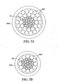
- the core may include, for example, a single wire, or stranded (e.g., helically wound wires. In some embodiments, for example, 7, 19 or 37 wires.
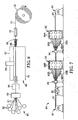
- Exemplary apparatus 80 for making cable according to the present invention is shown in FIGS 7 , 7A, and 7B .
- Spool of core material 81 is provided at the head of conventional planetary stranding machine 80, wherein spool 81 is free to rotate, with tension capable of being applied via a braking system where tension can be applied to the core during payoff (in some embodiments, in the range of 0-91 kg (0-200 lbs.)).
- Core 90 is threaded through bobbin carriages 82, 83, through the closing dies 84, 85, around capstan wheels 86 and attached to take-up spool 87.
- wires Prior to the application of the outer stranding layers, individual wires are provided on separate bobbins 88 which are placed in a number of motor driven carriages 82, 83of the stranding equipment.
- the range of tension required to pull wire 89A, 89B from the bobbins 88 is typically 4.5-22.7 kg (10-50 lbs.).
- Wires 89A, 89B of each layer are brought together at the exit of each carriage at a closing die 84, 85 and arranged over the central wire or over the preceding layer. Layers are helically stranded in opposite directions such that the outer layer results in a right hand lay.
- the central wire, or the intermediate unfinished stranded cable which will have one or more additional layers wound about it, is pulled through the center of the various carriages, with each carriage adding one layer to the stranded cable.
- the individual wires to be added as one layer are simultaneously pulled from their respective bobbins while being rotated about the central axis of the cable by the motor driven carriage. This is done in sequence for each desired layer. The result is a helically stranded cable 91 that can be cut and handled conveniently without loss of shape or unraveling.
- the cable maintains its helically stranded arrangement because during manufacture, the metallic wires are subjected to stresses, including bending stresses, beyond the yield stress of the wire material but below the ultimate or failure stress. This stress is imparted as the wire is helically wound about the relatively small radius of the preceding layer or central wire. Additional stresses are imparted at closing dies 84, 85 which apply radial and shear forces to the cable during manufacture. The wires therefore plastically deform and maintain their helically stranded shape.
- closing dies 84A, 85A are typically sized to minimize the deformation stresses on the wires of the layer being wound.
- the internal diameter of the closing die is tailored to the size of the external layer diameter.
- the closing die is sized such that it is in the range from 0-2.0% larger, relative to the external diameter of the cable. (i.e., the interior die diameters are in a range of 1.00 to 1.02 times the exterior cable diameter).
- Exemplary closing dies shown in FIGS. 7A and 7B are cylinders, and are held in position, for example, using bolts or other suitable attachments.
- the dies can be made, for example, of hardened tool steel.
- the resulting finished cable may pass through other stranding stations, if desired, and ultimately wound onto a take-up spool 87 of sufficient diameter to avoid cable damage.
- techniques known in the art for straightening the cable may be desirable.
- the finished cable can be passed through a straightener device comprised of rollers (each roller being for example, 10-15 cm (4-6 inches), linearly arranged in two banks, with, for example, 5-9 rollers in each bank.
- the distance between the two banks of rollers may be varied so that the rollers just impinge on the cable or cause severe flexing of the cable.
- the two banks of rollers are positioned on opposing sides of the cable, with the rollers in one bank matching up with the spaces created by the opposing rollers in the other bank.
- the two banks can be offset from each other.
- the cable flexes back and forth over the rollers, allowing the strands in the conductor to stretch to the same length, thereby reducing or eliminating slack strands.
- the core can be brought to the desired temperature, for example, by heating spooled core (e.g., core on a metal (e.g., steel) in an oven for several hours. The heated spooled core is placed on the pay-off spool (see, e.g., pay-off spool 81 in FIG.
- the spool at elevated temperature is in the stranding process while the core is still at or near the desired temperature (typically within about 2 hours).
- the wires on the payoff spools that form the outer layers of the cable may be at the ambient temperature. That is, it is desirable to have a temperature differential between the core and wires that form the outer layer during the stranding process.
- cables according to the present invention e.g., cables having a stress parameter less than zero
- it is desirable to hold the wires that are stranded around the core together for example, a tape overwrap, with or without adhesive, or a binder.
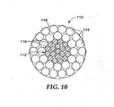
- a cross-sectional view of another exemplary cable according to the present invention 110 is shown in FIG. 10 .
- Cable 110 includes core 112 with wires core 116 and two layers of stranded wires 114, wherein cable 110 is wrapped with tape 118.
- Tape for example, can be applied to the resulting stranded cable to aid in holding the stranded wires together.
- the cable is be wrapped with adhesive tape using conventional taping equipment.
- exemplary machine for applying tape is commercially available from Watson Machine International (e.g., model 300 Concentric Taping Head).
- Exemplary tapes include metal foil tape (e.g., aluminum foil tape (available, for example, from the 3M Company, St Paul, MN under the trade designation "Foil/Glass Cloth Tape 363")), polyester backed tape; and tape having a glass reinforced backing.
- the tape has a thickness in a range from 0.05 mm to 0.13 mm (0.002 to 0.005 inch).
- the tape is wrapped such that each successive wrap overlaps the previous. In some embodiments, the tape is wrapped such that each successive wrap abuts the previous wrap without a gap and without overlap. In some embodiments, for example, the tape can be wrapped so that successive wraps are spaced to leave a gap between each wrap.
- the cable is wrapped while the cable is under tension during the stranding process.
- taping equipment would be located between the final closing die 85 and final capstan 86.
- a length of conductor is selected 30-300 meters in length and is terminated with conventional epoxy fittings, ensuring the layers substantially retain the same relative positions as in the as manufactured state.
- the outer wires are extended through the epoxy fittings and out the other side, and then reconstituted to allow for connection to electrical AC power using conventional terminal connectors.
- the epoxy fittings are poured in aluminum spelter sockets that are connected to turnbuckles for holding tension.
- a load cell is connected to a turnbuckle and then at both ends the tumbuckles are attached to pulling eyes.
- the eyes were connected to large concrete pillars, large enough to minimize end deflections of the system when under tension. For the test, the tension is pulled to a value in a range from 10 to 30 percent of the conductor rated breaking strength.
- the temperature is measured at three locations along the length of the conductor (at 1 ⁇ 4, 1 ⁇ 2 and 3 ⁇ 4 of the distance of the total (pulling-eye to pulling-eye) span) using nine thermocouples. At each location, the three thermocouples are positioned in three different radial positions within the conductor; between the outer wire strands, between the inner wire strands, and adjacent to (i.e., contacting) the outer core wires.
- the sag values are measured at three locations along the length of the conductor (at 1 ⁇ 4, 1 ⁇ 2 and 3 ⁇ 4 of the distance of the span) using pull wire potentiometers (available from SpaceAge Control, Inc, Palmdale, CA). These are positioned to measure the vertical movement of the three locations.
- AC current is applied to the conductor to increase the temperature to the desired value.
- the temperature of the conductor is raised from room temperature (about 20°C (68°F)) to about 240°C (464°F) at a rate in the range of 60-120°C/minute (140-248 °F/minute).
- the highest temperature of all of the thermocouples is used as the control.
- the effective "inner span” length is the horizontal distance between the 1 ⁇ 4 and 3 ⁇ 4 positions. This is the span length used to compute the sag.
- the measured sag and temperature data is plotted as a graph of sag versus temperature.
- a calculated curve is fit to the measured data using the Alcoa Sag10 graphic method available in a software program from Alcoa Fujikura Ltd., Greenville, SC under the trade designation "SAG10" (version 3.0 update 3.9.7).
- the stress parameter is a fitting parameter in "SAG10” labeled as the "built-in aluminum stress" which can be altered to fit other parameters if material other than aluminum is used (e.g., aluminum alloy), and which adjusts the position of the knee-point on the predicted graph and also the amount of sag in the high temperature, post-knee-point regime.
- First five numbers A0-A4 are coefficients of 4 th order polynomial that represents the initial wire curve times the area ratio:
- a Wire A total ⁇ ⁇ InitialWire A ⁇ 0 + A ⁇ 1 ⁇ ⁇ + A ⁇ 2 ⁇ ⁇ 2 + A ⁇ 3 ⁇ ⁇ 3 + A ⁇ 4 ⁇ ⁇ 4
- ⁇ is the conductor elongation in % and ⁇ is the stress in psi
- B0-B4 are coefficients of 4 th order polynomial that represents the final 10 year creep curve of the wire times the area ratio:
- a Wire A total ⁇ ⁇ FinalWire B ⁇ 0 + B ⁇ 1 ⁇ ⁇ + B ⁇ 2 ⁇ ⁇ 2 + B ⁇ 3 ⁇ ⁇ 3 + B ⁇ 4 ⁇ ⁇ 4
- C ⁇ (Al) is the coefficient of thermal expansion of the wire.
- C0-C4 are coefficients of 4 th order polynomial that represents the initial curve times the area ratio for composite core only.
- D0-D4 are coefficients of 4 th order polynomial that represents the final 10 year creep curve of the composite core times the area ratio
- ⁇ (core) is the coefficient of thermal expansion of the composite core.
- the best fit matches (i) the calculated curve to the measured data by varying the value of the stress parameter, such that the curves match at high temperatures (140-240°C), and (ii) the inflection point (knee-point) of the measured curve closely matches the calculated curve, and (iii) the initial calculated sag is required to match the initial measured sag.
- the value of the stress parameter to gain the best fit to the measured data is thus derived. This result is the "Stress Parameter" for the cable.
- Cable according to the present invention can be used in a variety of applications including in overhead electrical power transmission cables.
- the wire for the Illustrative Example cable was prepared as follows.
- the wire was made using apparatus 60 shown in FIG. 6 .
- Eleven (11) tows of 10,000 denier alpha alumina fiber (marketed by the 3M Company, St. Paul under the trade designation "NEXTEL 610") where supplied from supply spools 62, collimated into a circular bundle, and heat-cleaned by passing through 1-5 m (5 ft.) long alumina tube 63 heated to 1100°C at 305cm/min (120 in./min).
- Heat-cleaned fibers 61 were then evacuated in vacuum chamber 64 before entering crucible 67 containing melt (molten metal) 65 of metallic aluminum (99.99% Al) matrix material (obtained from Beck Aluminum Co., Pittsburgh, PA).
- the fibers were pulled from supply spools 62 by caterpuller 70.
- Ultrasonic probe 66 was positioned in melt 65 in the vicinity of the fiber to aid in infiltrating melt 65 into tows of fibers 61.
- the molten metal of wire 71 cooled and solidified after exiting crucible 67 through exit die 68, although some cooling likely occurred before the wire 71 fully exited crucible 67. Further, cooling of wire 71 was enhanced by streams of nitrogen gas delivered through cooling device 69 that impinged on wire 71. Wire 71 was collected onto spool 72.
- Fibers 61 were evacuated before entering the melt 67.
- the pressure in the vacuum chamber was about 20 torr.
- Vacuum system 64 had a 25 cm long alumina entrance tube sized to match the diameter of the bundle of fiber 61.
- Vacuum chamber 64 was 21 cm long, and 10 cm in diameter.
- the capacity of the vacuum pump was 0.37 m 3 /minute.
- the evacuated fibers 61 were inserted into the melt 65 through a tube on the vacuum system 64 that penetrated the metal bath (i.e., the evacuated fibers 61were under vacuum when introduced into the melt 54.
- the inside diameter of the exit tube matched the diameter of the fiber bundle 61. A portion of the exit tube was immersed in the molten metal to a depth of 5 cm.
- a vibrating horn 66 positioned in the molten metal 65 so that it was in close proximity to the fibers 61.
- Horn 66 was driven to vibrate at 19.7 kHz and an amplitude in air of 0.18 mm (0.007 in.).
- the horn was connected to a titanium waveguide which, in turn, was connected to the ultrasonic transducer (obtained from Sonics & Materials, Danbury, CT).
- the fibers 61 were within 2.5 mm of the horn tip.
- the horn tip was, made of a niobium alloy of composition 91 wt.% Nb-9 wt.% Mo (obtained from PMTI, Pittsburgh, PA).
- the alloy was fashioned into a cylinder 12.7 cm in length (5 in.) and 2.5 cm (1 in.) in diameter.
- the cylinder was tuned to the desired vibration frequency of 19.7 kHz by altering its length.
- the molten metal 65 was degassed (e.g., reducing the amount of gas (e.g., hydrogen) dissolved in the molten metal) prior to infiltration.
- a portable rotary degassing unit available from Brummund Foundry Inc, Chicago, IL, was used.
- the gas used was Argon, the Argon flow rate was 1050 liters per minute, the speed was provided by the air flow rate to the motor set at 50 liters per minute, and duration was 60 minutes.
- the silicon nitride exit die 68 was configured to provide the desired wire diameter.
- the internal diameter of the exit die was 2.67 mm (0.105 in.).
- the stranded core was stranded on stranding equipment at Wire Rope Company in Montreal, Canada.
- the cable had one wire in the center, and six wires in the first layer with a right hand lay.
- the individual wires Prior to being helically wound together, the individual wires were provided on separate bobbins which were then placed in a motor driven carriage of the stranding equipment. The carriage held the six bobbins for the layer of the finished stranded cable.
- the wires of the layer were brought together at the exit of the carriage and arranged over the central wire.
- the central wire was pulled through the center of the carriage, with the carriage adding one layer to the stranded cable.
- the individual wires added as one layer were simultaneously pulled from their respective bobbins while being rotated about the central axis of the cable by the motor driven carriage. The result was a helically stranded core.
- the stranded core was wrapped with adhesive tape using conventional taping equipment (model 300 Concentric Taping Head from Watson Machine International, Paterson, NJ).
- the tape backing was aluminum foil tape with fiber glass, and had a pressure sensitive silicone adhesive (obtained under the trade designation "Foil/Glass Cloth Tape 363" from 3M Company, St. Paul, MN).
- the total thickness of tape 18 was 0.0072 inch (0.18 mm).
- the tape was 0.75 inch (1.90 cm) wide.
- the average diameter of the finished core was 0.324 inch (8.23 mm) and the lay length of the stranded layer was 21.3 inches (54.1 cm).
- the first trapezoidal aluminum alloy wires were prepared from aluminum/zirconium rod (9.53 mm (0.375 inch) diameter; obtained from Lamifil N.V., (Hemiksem, Belguim under the trade designation "ZTAL") with a tensile strength of 153.95 MPa (22,183 psi), an elongation of 13.3%, and an electrical conductivity of 60.4 % IACS.
- the second trapezoidal wires were prepared from aluminum/zirconium rod of 9.53 mm (0.375 inch) diameter (“ZTAL") with a tensile strength of 132.32 MPa (19,191 psi), an elongation of 10.4%, and an electrical conductivity of 60.5 %IACS.
- the rods were drawn down at room temperature using five intermediate dies as is known in the art, and finally a trapezoidal shaped forming die.
- the drawing dies were made of tungsten carbide.
- the geometry of the tungsten carbide die had a 60° entrance angle, a 16-18° reduction angle, a bearing length 30% of the die diameter, and a 60° back relief angle.
- the die surface was highly polished.
- the die was lubricated and cooled using a drawing oil.
- the drawing system delivered the oil at a rate set in the range of 60-100 liters per minute per die, with the temperature set in the range of 40-50°C.
- the last forming die comprised two horizontal hardened steel (60 RC hardness) forming rolls, with highly polished working surfaces.
- the design of the roll grooves was based on the required trapezoidal profile.
- the rolls were installed on a rolling stand that was located between the drawbox and the outside drawblock.
- the final forming roll reduction reduced the area of the wire about 23.5%.
- the amount of area reduction was sufficient to move the metal into the corners of the roll grooves and adequately fill the space between the forming rolls.
- the forming rolls were aligned and installed so that the cap of the trapezoidal wires faced the surfaces of the drawblock and the bobbin drum. After forming, the wire profile was checked and verified using a template.
- the "effective diameter" of the trapezoidal shape refers to the diameter of a circle that has the same area as the cross-sectional area of the trapezoidal shape.
- a cable was made by Nexans, Weybum, SK using a conventional planetary stranding machine and the core and (inner and outer) wires described above for Comparative Example.
- a schematic of the apparatus 80 for making cable is shown in FIGS. 7 , 7A, and 7B .
- Spool of core 81 was provided at the head of a conventional planetary stranding machine 80, wherein spool 81 was free to rotate, with tension capable of being applied via a braking system.
- the tension applied to the core during payoff was 45 kg (100 lbs.).
- the core was input at room temperature (about 23°C (73°F)).
- the core was threaded through the center of the bobbin carriages 82, 83, through closing dies 84, 85, around capstan wheels 86 and attached to conventional take-up (152 cm (60 in.) diameter) spool 87.
- the core material and wires for a given layer were brought into contact via a closing die 84, 85, as applicable.
- the closing dies were cylinders (see FIGS. 7A and 7B ) and were held in position using bolts.
- the dies were made of hardened tool steel, and were capable of being fully closed.
- the finished cable was passed through capstan wheels 86, and ultimately wound onto (91 cm diameter (36 inch)) take-up spool 87.
- the finished cable was passed through a straightener device comprised of rollers (each roller being 12.5 cm (5 inches)), linearly arranged in two banks, with 7 rollers in each bank. The distance between the two banks of rollers was set so that the rollers just impinged on the cable.
- the two banks of rollers were positioned on opposing sides of the cable, with the rollers in one bank matching up with the spaces created by the opposing rollers in the other bank. Thus, the two banks were offset from each other.
- the cable flexed back and forth over the rollers, allowing the strands in the conductor to stretch to the same length, thereby eliminating slack strands.
- the inner layer consisted of 8 trapezoidal wires with an outside layer diameter of 15.4 mm (0.608 in.), a mass per unit length of 353 kg/km (237 lbs./kft.) with the left hand lay of 20.3 cm (8 in.).
- the closing blocks (made from hardened tool steel; 60 Rc hardness) for the inner layer were set at an internal diameter of 15.4 mm (0.608 in.). Thus the closing blocks were set at exactly the same diameter as the cable diameter.
- the outer layer consisted of 12 trapezoidal wires with an outside layer diameter of 22.9 mm (0.9015 in.), a mass per unit length of 507.6 kg/km (341.2 lbs./kft) with the right hand lay of 25.9 cm (10.2 in.).
- the total mass per unit length of aluminum alloy wires was 928.8 kg/km (624.3 lbs./kft.)
- total mass per unit length of the core was 136.4 kg/km (91.7 lbs./kft.)
- the total conductor mass per unit length was 1065 kg/km (716.0 lbs./kft.).
- the closing blocks (made from hardened tool steel; 60 Rc hardness) for the outer layer were set at an internal diameter of 0.9015 in. (22.9 mm). Thus the closing blocks were set at exactly the same diameter as the final cable diameter.
- the inner wire and outer wire tension (as pay-off bobbins) was measured using a hand held force gauge (available McMaster-Card, Chicago, IL) and set to be in the range of 13.5-15 kg (29-33 lbs.) and the core pay-off tension was set by brake using the same measurement method as the bobbins at about 90 kg (198 lbs.). Further, no straightener was used, and the cable was not spooled but left to run straight and to lay out on the floor. The core was input at room temperature (about 23°C(73°F)).
- the stranding machine was run at 15m/min. (49 ft/min.), driven using conventional capstan wheels, a standard straightening device, and a conventional 152 cm (60 in.) diameter take-up spool.
- the resulting conductor was tested using the following "Cut-end Test Method".
- a section of conductor to be tested was laid out straight on the floor, and a sub-section 3.1-4.6 m (10-15 ft.) long was clamped at both ends.
- the conductor was then cut to isolate the section, still clamped at both ends. One clamp was then released and no layer movement was observed.
- the section of conductor was then inspected for movement of layers relative to each other. The movement of each layer was measured using a ruler to determine the amount of movement relative to the core.
- the outer aluminum layers retracted relative to the composite core; taking the core as the zero reference position, the inner aluminum layer retracted 0.16 in. (4 mm) and the outer layer retracted 0.31 in. (8 mm).
- the Illustrative Example cable was also evaluated by Kinectrics, Inc. Toronto, Ontario, Canada using the following "Sag Test Method I".
- a length of conductor was terminated with conventional epoxy fittings, ensuring the layers substantially retain the same relative positions as in the as manufactured state, except the aluminum/zirconium wires were extended through the epoxy fittings and out the other side, and then reconstituted to allow for connection to electrical AC power using conventional terminal connectors.
- the epoxy fittings were poured in aluminum spelter sockets that were connected to turnbuckles for holding tension.
- a load cell was connected (5000 kilograms (kg) capacity) to a turnbuckle and then at both ends the turnbuckles were attached to pulling eyes.
- the eyes were connected to large concrete pillars, large enough to minimize end deflections of the system when under tension.
- the tension was pulled to 20% of the conductor rated breaking strength.
- 2082 kg (4590 lb) was applied to the cable.
- the temperature was measured at three locations along the length of the conductor (at 1 ⁇ 4, 1 ⁇ 2 and 3 ⁇ 4 of the distance of the total (pulling-eye to pulling-eye) span) using nine thermocouples (three at each location; J-type available from Omega Corporation, Stamford, CT).
- the three thermocouples were positioned in three different radial positions within the conductor; between the outer aluminum strands, between the inner aluminum strands, and adjacent to (i.e., contacting) the outer core wires.
- the sag values were measured at three locations along the length of the conductor (at 1 ⁇ 4, 1 ⁇ 2 and 3 ⁇ 4 of the distance of the span) using pull wire potentiometers (available from SpaceAge Control, Inc, Palmdale, CA). These were positioned to measure the vertical movement of the three locations. AC current was applied to the conductor to increase the temperature to the desired value. The temperature of the conductor was raised from room temperature (about 20°C (68°F)) to about 240°C (464°F) at a rate in the range of 60-120°C/minute (140-248 °F/minute). The highest temperature of all of the thermocouples was used as the control. About 1200 amps was required to achieve 240°C (464°F).
- Sag total Sag 1 / 2 - Sag 1 / 4 + Sag 3 / 4 2
- Table 3 summarizes the fixed input test parameters. Table 3 Parameter Value Total span length 68.6 m (225 ft.) Effective span length* - m (ft.) 65.5 m (215 ft.) Height of North fixed point 2.36m (93.06 in.) Height of South fixed point 2.47 m (97.25 in.) Conductor weight 1.083 kg/m (0.726 lbs./ft.) Initial Tension (@ 20% RTS*) 2082 kg (4590 lb) Load cell capacity 5000 kg (1100 lbs) load cell *rated tensile strength
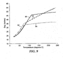
- the resulting sag and temperature data (“Resulting Data” for Illustrative Example) was plotted and then a calculated curve was fit using the Alcoa Sag10 graphic method available in a software program from Alcoa Fujikura Ltd., Greenville, SC under the trade designation "SAG10" (version 3.0 update 3.9.7).
- the stress parameter was a fitting parameter in "SAG10” labeled as the "built-in aluminum stress” which adjusted the position of the knee-point on the predicted graph and also the amount of sag in the high temperature, post-knee-point regime.
- a description of the stress parameter theory was provided in the Alcoa Sag10 Users Manual (Version 2.0): Theory of Compressive Stress in Aluminum of ACSR.
- FIG. 8 shows the sag calculated by Sag10 (line 82) and the measured Sag (plotted data 83).
- First five numbers A0-A4 are coefficients of 4 th order polynomial that represents the initial aluminum curve times the area ratio:
- a Wire A total ⁇ ⁇ InitialWire A ⁇ 0 + A ⁇ 1 ⁇ ⁇ + A ⁇ 2 ⁇ ⁇ 2 + A ⁇ 3 ⁇ ⁇ 3 + A ⁇ 4 ⁇ ⁇ 4
- ⁇ is the conductor elongation in % and ⁇ is the stress in psi
- B0-B4 are coefficients of 4 th order polynomial that represents the final 10 year creep curve of the aluminum times the area ratio:
- a Wire A total ⁇ ⁇ FinalWire B ⁇ 0 + B ⁇ 1 ⁇ ⁇ + B ⁇ 2 ⁇ ⁇ 2 + B ⁇ 3 ⁇ ⁇ 3 + B ⁇ 4 ⁇ ⁇ 4
- C ⁇ (Al) is the coefficient of thermal expansion of aluminum.
- C0-C4 are coefficients of 4 th order polynomial that represents the initial curve times the area ratio for composite core only.
- D0-D4 are coefficients of 4 th order polynomial that represents the final 10 year creep curve of the composite core times the area ratio
- ⁇ (core) is the coefficient of thermal expansion of the composite core.
- a cable would be made as described in Illustrative Example except as follows: the composite wires stranded to form the core would consist of carbon fiber composite (carbon fibers in a bismaleic amid resin matrix) wires. These wires are available from Tokyo Rope Manufacturing Company, Ltd. Tokyo, Japan under the trade designation"CFCC". The composite wires would have the same diameter as the composite wires of the Illustrative Example.
- the Alcoa SagIO Graphic Method model described in the Illustrative Example was used to predict the sag vs temperature behavior of cables described in Prophetic Example 1.
- Sag vs temperature curves were generated using the Sag10 model and method of the Illustrative Example.
- the conductor parameters shown in Tables 8-11 (below) were entered into the Sag10 Software.
- the value for the compressive stress parameter for Prophetic Example 1 was 3.5 MPa (500 psi). Additionally a sag vs temperature curve was generated for a compressive stress value of 55 MPa (8000 psi).
- FIG. 9 shows the sag vs temperature curves of the Illustrative Example and Prophetic Example 1.
- the measured data of the Illustrative Example is shown as plotted data 93 and the calculated curve of the Illustrative Example is shown as line 92.
- the calculated curve for Prophetic Example 1 which used a stress parameter of 3.5 MPa (500 psi) is shown as line 94.
- the additional calculated curve with a stress parameter of 55 MPa (8000 psi) is shown as line 96.
Landscapes
- Engineering & Computer Science (AREA)
- Manufacturing & Machinery (AREA)
- Ropes Or Cables (AREA)
- Non-Insulated Conductors (AREA)
- Suspension Of Electric Lines Or Cables (AREA)
Description
- In general, composites (including metal matrix composites (MMCs)) are known. Composites typically include a matrix reinforced with fibers, particulates, whiskers, or fibers (e.g., short or long fibers). Examples of metal matrix composites include aluminum matrix composite wires (e.g., silicon carbide, carbon, boron, or polycrystalline alpha alumina fibers embedded in an aluminum matrix), titanium matrix composite tapes (e.g., silicon carbide fibers embedded in a titanium matrix), and copper matrix composite tapes (e.g., silicon carbide or boron fibers embedded in a copper matrix). Examples of polymer matrix composites include carbon or graphite fibers in an epoxy resin matrix, glass or aramid fibers in a polyester resin, and carbon and glass fibers in an epoxy resin.
- One use of composite wire (e.g., metal matrix composite wire) is as a reinforcing member in bare overhead electrical power transmission cables. One typical need for cables is driven by the need to increase the power transfer capacity of existing transmission infrastructure.
- Desirable performance requirements for cables for overhead power transmission applications include corrosion resistance, environmental endurance (e.g., UV and moisture), resistance to loss of strength at elevated temperatures, creep resistance, as well as relatively high elastic modulus, low density, low coefficient of thermal expansion, high electrical conductivity, and high strength. Although overhead power transmission cables including aluminum matrix composite wires are known, for some applications there is a continuing desire, for example, for more desirable sag properties.
- In one aspect, the present invention provides a cable, comprising:
- a longitudinal core having a thermal expansion coefficient and comprising at least one of aramid, ceramic, boron, poly(p-phenylene-2,6-benzobisoxazole), graphite, carbon, titanium, tungsten, or shape memory alloy; and a plurality of wires collectively having a thermal expansion coefficient greater than the thermal expansion coefficient of the core, wherein the plurality of wires comprise at least one of aluminum wires, copper wires, aluminum alloy wires, or copper alloy wires, and wherein the plurality of wires are stranded around the core, and wherein the cable has a stress parameter not greater than 5 MPa, 4 MPa, 3 MPa, 2 MPa, 1 MPa, or even not greater than 0 MPa; in some embodiments, in a range from 0 MPa to 5 MPa, with the proviso that if the longitudinal core comprises metal matrix composite wire, the core separately comprises (i.e., not being part of the metal matrix composite wire) at least one of the aramid, ceramic, boron, poly(p-phenylene-2,6-benzobisoxazole), graphite, carbon, titanium, tungsten, or shape memory alloy. In some embodiments, the plurality of wires have a tensile breaking strength of at least 90 MPa, or even at least 100 MPa (calculated according to ASTM B557/B557M (1999).
- In some embodiments, the core comprises fibers (typically continuous fibers) of at least one of the aramid, ceramic, boron, poly(p-phenylene-2,6-benzobisoxazole), graphite, carbon, titanium, tungsten, or shape memory alloy. In some embodiments, the core comprises a composite comprising fibers and la matrix material (e.g., metal and/or polymeric material).
- As used herein, the following terms are defined as indicated, unless otherwise specified herein:
- "ceramic" means glass, crystalline ceramic, glass-ceramic, and combinations thereof.
- "continuous fiber" means a fiber having a length that is relatively infinite when compared to the average fiber diameter. Typically, this means that the fiber has an aspect ratio (i.e., ratio of the length of the fiber to the average diameter of the fiber) of at least 1 x 10⁵ (in some embodiments, at least 1 x 10⁶, or even at least 1 x 10⁷). Typically, such fibers have a length on the order of at least 50 meters, and may even have lengths on the order of kilometers or more.
- "shape memory alloy" refers to a metal alloy that undergoes a Martensitic transformation such that the metal alloy is deformable by a twinning mechanism below the transformation temperature, wherein such deformation is reversable when the twin structure reverts to the original phase upon heating above the transformation temperature.
- Cables according to the present invention are useful, for example, as electric power transmission cables. Typically, cables according to the present invention exhibit improved sag properties (i.e., reduced sag).
-
-
FIGS. 1-5 are schematic, cross-sectional views of exemplary embodiments of cables in accordance with the present invention. -
FIG. 6 is a schematic view of an exemplary ultrasonic infiltration apparatus used to infiltrate fibers with molten metals in accordance with the present invention. -
FIGS. 7 ,7A, and 7B are schematic views of an exemplary stranding apparatus used to make cable in accordance with the present invention. -
FIG. 8 is a plot of cable sag data for the Illustrative Example. -
FIG. 9 is a plot of cable sag data for the Illustrative Example and Prophetic Example 1. -
FIG. 10 is schematic, cross-sectional view of exemplary embodiment of a cable in accordance with the present invention. - The present invention relates to cables and methods of making cables. A cross-sectional view of an exemplary cable according to the
present invention 10 is shown inFIG. 1 .Cable 10 includescore 12 and two layers of strandedround wires 14, wherein thecore 12 includes wires 16 (as shown, composite wires). - A cross-sectional view of another exemplary cable according to the
present invention 20 is shown inFIG. 2 .Cable 20 includescore 22 and three layers of strandedwires 24, whereincore 22 includes wires 26 (as shown, composite wires). - A cross-sectional view of another exemplary cable according to the
present invention 30 is shown inFIG. 3 .Cable 30 includescore 32 and strandedtrapezoidal wires 34, wherein thecore 32 includes wires 36 (as shown, composite wires). - A cross-sectional view of another exemplary cable according to the
present invention 40 is shown inFIG. 4 .Cable 40 includescore 42 and strandedwires 44. - In some embodiments, the core has a longitudinal thermal expansion coefficient in a range from about 5.5 ppm/°C to about 7.5 ppm/°C over at least a temperature range from about-75°C to about 450°C.
- Examples of materials comprising the core include aramid, ceramic, boron, poly(p-phenylene-2,6-benzobisoxazole), graphite, carbon, titanium, tungsten, and/or shape memory alloy. In some embodiments, the materials are in the form of fibers (typically continuous fibers). In some embodiments, cores comprising aramid have a longitudinal thermal expansion coefficient in a range from about -6 ppm/°C to about 0 ppm/°C over at least a temperature range from about 20°C to about 200°C. In some embodiments, the cores comprising ceramic have a longitudinal thermal expansion coefficient in a range from about 3 ppm/°C to about 12 ppm/°C over at least a temperature range from about 20°C to about 600°C. In some embodiments, cores comprising boron have a longitudinal thermal expansion coefficient in a range from about 4 ppm/°C to about 6 ppm/°C over at least a temperature range from about 20°C to about 600°C. In some embodiments, cores comprising poly(p-phenylene-2,6-benzobisoxazole) have a longitudinal thermal expansion coefficient in a range from about -6 ppm/°C to about 0 ppm/°C over at least a temperature range from about 20°C to about 600°C. In some embodiments, cores comprising graphite have a longitudinal thermal expansion coefficient in a range from about -2 ppm/°C to about 2 ppm/°C over at least a temperature range from about 20°C to about 600°C. In some embodiments, cores comprising carbon have a longitudinal thermal expansion coefficient in a range from about -2 ppm/°C to about 2 ppm/°C over at least a temperature range from about 20°C to about 600°C. In some embodiments, cores comprising titanium have a longitudinal thermal expansion coefficient in a range from about 10 ppm/°C to about 20 ppm/°C over at least a temperature range from about 20°C to about 800°C. In some embodiments, cores comprising tungsten have a longitudinal thermal expansion coefficient in a range from about 8 ppm/°C to about 18 ppm/°C over at least a temperature range from about 20°C to about 1000°C. In some embodiments, cores comprising shape memory alloy have a longitudinal thermal expansion coefficient in a range from about 8 ppm/°C to about 25 ppm/°C over at least a temperature range from about 20°C to about 1000°C. In some embodiments, cores comprising glass have a longitudinal thermal expansion coefficient in a range from about 4 ppm/°C to about 10 ppm/°C over at least a temperature range from about 20°C to about 600°C.
- Examples of fibers for the core include aramid fibers, ceramic fibers, boron fibers, poly(p-phenylene-2,6-benzobisoxazole) fibers, graphite fibers, carbon fibers, titanium fibers, tungsten fibers, and/or shape memory alloy fibers.
- Exemplary boron fibers are commercially available, for example, from Textron Specialty Fibers, Inc. of Lowell, MA. Typically, such fibers have a length on the order of at least 50 meters, and may even have lengths on the order of kilometers or more. Typically, the continuous boron fibers have an average fiber diameter in a range from about 80 micrometers to about 200 micrometers. More typically, the average fiber diameter is no greater than 150 micrometers, most typically in a range from 95 micrometers to 145 micrometers. In some embodiments, the boron fibers have an average tensile strength of at least 3 GPa, and or even at least 3.5 GPa. In some embodiments, the boron fibers have a modulus in a range from about 350 GPa to about 450 GPa, or even in a range from about 350 GPa to about 400 GPa.
- In some embodiments, the ceramic fibers have an average tensile strength of at least 1.5 GPa, 2 GPa, 3 GPa, 4 GPa, 5 GPa, 6 GPa, and or even at least 6.5 GPa. In some embodiments, the ceramic fibers have a modulus in a range from 140 GPa to about 500 GPa, or even in a range from 140 GPa to about 450 GPa.
- Exemplary carbon fibers are marketed, for example, by Amoco Chemicals of Alpharetta, GA under the trade designation "THORNEL CARBON" in tows of 2000, 4000, 5,000, and 12,000 fibers, Hexcel Corporation of Stamford, CT, from Grafil, Inc. of Sacramento, CA (subsidiary of Mitsubishi Rayon Co.) under the trade designation "PYROFIL", Toray of Tokyo, Japan, under the trade designation "TORAYCA", Toho Rayon of Japan, Ltd. under the trade designation "BESFIGHT", Zoltek Corporation of St. Louis, MO under the trade designations "PANEX" and "PYRON", and Inco Special Products of Wyckoff, NJ (nickel coated carbon fibers), under the trade designations "12K20" and "12K50". Typically, such fibers have a length on the order of at least 50 meters, and may even have lengths on the order of kilometers or more. Typically, the continuous carbon fibers have an average fiber diameter in a range from about 4 micrometers to about 12 micrometers, about 4.5 micrometers to about 12 micrometers, or even about 5 micrometers to about 10 micrometers. Insome embodiments, the carbon fibers have an average tensile strength of at least 1.4 GPa, at least 2.1 GPa, at least 3.5 GPa, or even at least 5.5 GPa. In some embodiments, the carbon fibers have a modulus greater than 150 GPa to no greater than 450 GPa, or even no greater than 400 GPa.
- Exemplary graphite fibers are marketed, for example, by BP Amoco of Alpharetta, GA, under the trade designation "T-300", in tows of 1000, 3000, and 6000 fibers. Typically, such fibers have a length on the order of at least 50 meters, and may even have lengths on the order of kilometers or more. Typically, the continuous graphite fibers have an average fiber diameter in a range from about 4 micrometers to about 12 micrometers, about 4.5 micrometers to about 12 micrometers, or even about 5 micrometers to about 10 micrometers. In some embodiments, the graphite fibers have an average tensile strength of at least 1.5 GPa, 2 GPa, 3 GPa, or even at least 4 GPa. In some embodiments, the graphite fibers have a modulus in a range from about 200 GPa to about 1200 GPa, or even about 200 GPa to about 1000 GPa.
- Exemplary titanium fibers are available, for example, from TIMET, Henderson, NV. Typically, such fibers have a length on the order of at least 50 meters, and may even have lengths on the order of kilometers or more. Typically, the continuous titanium fibers have an average fiber diameter in a range from 50 micrometers to about 250 micrometers. In some embodiments, the titanium fibers have an average tensile strength of at least 0.7 GPa, 1 GPa, 1.5 GPa, 2 GPa, or even at least 2.1 GPa. In some embodiments, the ceramic fibers have a modulus in a range from about 85 GPa to about 100 GPa, or even from about 85 to about 95 GPa.
- Exemplary tungsten fibers are available, for example, from California Fine Wire Company, Grover Beach, CA. Typically, such fibers have a length on the order of at least 50 meters, and may even have lengths on the order of kilometers or more. Typically, the continuous tungsten fibers have an average fiber diameter in a range from about 100 micrometers to about 500 micrometers about 150 micrometers to about 500 micrometers, or even from about 200 micrometers to about 400 micrometers. In some embodiments, the tungsten fibers have an average tensile strength of at least 0.7 GPa, 1 GPa, 1.5 GPa, 2 GPa, or even at least 2.3 GPa. In some embodiments, the tungsten fibers have a modulus greater than 400 GPa to approximately no greater than 420 GPa, or even no greater than 415 GPa.
- Exemplary shape memory alloy fibers are available, for example, from Johnson Matthey, West Whiteland, PA. Typically, such fibers have a length on the order of at least 50 meters, and may even have lengths on the order of kilometers or more. Typically, the continuous shape memory alloy fibers have an average fiber diameter in a range from about 50 micrometers to about 400 micrometers, about 50 to about 350 micrometers, or even about 100 micrometers to 300 micrometers. In some embodiments, the shape memory alloy fibers have an average tensile strength of at least 0.5 GPa, and or even at least 1 GPa. In some embodiments, the shape memory alloy fibers have a modulus in a range from about 20 GPa to about 100 GPa, or even from about 20 GPA to about 90 GPa.
- Exemplary aramid fibers are available, for example, from DuPont, Wilmington, DE under the trade designation "KEVLAR". Typically, such fibers have a length on the order of at least 50 meters, and may even have lengths on the order of kilometers or more. Typically, the continuous aramid fibers have an average fiber diameter in a range from about 10 micrometers to about 15 micrometers. In some embodiments, the aramid fibers have an average tensile strength of at least 2.5 GPa, 3 GPa, 3.5 GPa, 4 GPa, or even at least 4.5 GPa. In some embodiments, the aramid fibers have a modulus in a range from about 80 GPa to about 200 GPa, or even about 80 GPa to about 180 GPa.
- Exemplary poly(p-phenylene-2,6-benzobisoxazole) fibers are available, for example, from Toyobo Co., Osaka, Japan under the trade designation "ZYLON". Typically, such fibers have a length on the order of at least 50 meters, and may even have lengths on the order of kilometers or more. Typically, the continuous poly(p-phenylene-2,6-benzobisoxazole) fibers have an average fiber diameter in a range from about 8 micrometers to about 15 micrometers. In some embodiments, the poly(p-phenylene-2,6-benzobisoxazole) fibers have an average tensile strength of at least 3 GPa, 4 GPa, 5 GPa, 6 GPa, or even at least 7 GPa. In some embodiments, the poly(p-phenylene-2,6-benzobisoxazole) fibers have a modulus in a range from about 150 GPa to about 300 GPa, or even about 150 GPa to about 275 GPa.
- Examples of ceramic fiber include metal oxide (e.g., alumina) fibers, boron nitride fibers, silicon carbide fibers, and combination of any of these fibers. Typically, the ceramic oxide fibers are crystalline ceramics and/or a mixture of crystalline ceramic and glass (i.e., a fiber may contain both crystalline ceramic and glass phases). Typically, such fibers have a length on the order of at least 50 meters, and may even have lengths on the order of kilometers or more. Typically, the continuous ceramic fibers have an average fiber diameter in a range from about 5 micrometers to about 50 micrometers, about 5 micrometers to about 25 micrometers about 8 micrometers to about 25 micrometers, or even about 8 micrometers to about 20 micrometers. In some embodiments, the crystalline ceramic fibers have an average tensile strength of at least 1.4 GPa, at least 1.7 GPa, at least 2.1 GPa, and or even at least 2.8 GPa. In some embodiments, the crystalline ceramic fibers have a modulus greater than 70 GPa to approximately no greater than 1000 GPa, or even no greater than 420 GPa.
- Examples of monofilament ceramic fibers include silicon carbide fibers. Typically, the silicon carbide monofilament fibers are crystalline and/or a mixture of crystalline ceramic and glass (i.e., a fiber may contain both crystalline ceramic and glass phases). Typically, such fibers have a length on the order of at least 50 meters, and may even have lengths on the order of kilometers or more. Typically, the continuous silicon carbide monofilament fibers have an average fiber diameter in a range from about 100 micrometers to about 250 micrometers. In some embodiments, the crystalline ceramic fibers have an average tensile strength of at least 2.8 GPa, at least 3.5 GPa, at least 4.2 GPa and or even at least 6 GPa. In some embodiments, the crystalline ceramic fibers have a modulus greater than 250 GPa to approximately no greater than 500 GPa, or even no greater than 430 GPa.
- Further, exemplary glass fibers are available, for example, from Corning Glass, Corning, NY. Typically, the continuous glass fibers have an average fiber diameter in a range from about 3 micrometers to about 19 micrometers. In some embodiments, the glass fibers have an average tensile strength of at least 3 GPa, 4 GPa, and or even at least 5 GPa. In some embodiments, the glass fibers have a modulus in a range from about 60 GPa to 95 GPa, or about 60 GPa to about 90 GPa.
- In some embodiments of ceramic and carbon fibers are in tows. Tows are known in the fiber art and refer to a plurality of (individual) fibers (typically at least 100 fibers, more typically at least 400 fibers) collected in a roving-like form. In some embodiments, tows comprise at least 780 individual fibers per tow, and in some cases, at least 2600 individual fibers per tow. Tows of ceramic fibers are available in a variety of lengths, including 300 meters, 500 meters, 750 meters, 1000 meters, 1500 meters, 1750 meters, and longer. The fibers may have a cross-sectional shape that is circular or elliptical. In some embodiments of carbon fibers, tows comprise at least 2,000 5,000 12,000, or even at least 50,000 individual fibers per tow.
- Alumina fibers are described, for example, in
U.S. Pat. No. 4,954,462 (Wood et al. ) and5,185,29 (Wood et al. ). In some embodiments, the alumina fibers are polycrystalline alpha alumina fibers and comprise, on a theoretical oxide basis, greater than 99 percent by weight Al2O3 and 0.2-0.5 percent by weight SiO2, based on the total weight of the alumina fibers. In another aspect, some desirable polycrystalline, alpha alumina fibers comprise alpha alumina having an average grain size of less than 1 micrometer (or even, in some embodiments, less than 0.5 micrometer). In another aspect, in some embodiments, polycrystalline, alpha alumina fibers have an average tensile strength of at least 1.6 GPa (in some embodiments, at least 2.1 GPa, or even, at least 2.8 GPa). Exemplary alpha alumina fibers are marketed under the trade designation "NEXTEL 610" by 3M Company, St. Paul, MN. - Aluminosilicate fibers are described, for example, in
U.S. Pat. No. 4,047,965 (Karst et al ). Exemplary aluminosilicate fibers are marketed under the trade designations "NEXTEL 440", "NEXTEL 550", and "NEXTEL 720" by 3M Company of St. Paul, MN. - Aluminoborosilicate fibers are described, for example, in
U.S. Pat. No. 3,795,524 (Sowman ). Exemplary aluminoborosilicate fibers are marketed under the trade designation "NEXTEL 312" by 3M Company. - Boron nitride fibers can be made, for example, as described in
U.S. Pat No. 3,429,722 (Economy ) and5,780,154 (Okano et al. ). - Exemplary silicon carbide fibers are marketed, for example, by COI Ceramics of San Diego, CA under the trade designation "NICALON" in tows of 500 fibers, from Ube Industries of Japan, under the trade designation "TYRANNO", and from Dow Corning of Midland, MI under the trade designation "SYLRAMIC".
- Exemplary silicon carbide monofilament fibers are marketed, for example, by Textron Specialty Materials of Lowell, MA under the trade designation "SCS-9", "SCS-6" and "Ulra-SCS", and from Atlantic Research Corporation, of Gainesville, VA under the trade designation "Trimarc".
- Commercially available fibers typically include an organic sizing material added to the fiber during manufacture to provide lubricity and to protect the fiber strands during handling. Also the sizing may aid in handling during pultrusion with polymers to make polymer composite core wires. The sizing may be removed, for example, by dissolving or burning the sizing away from the fibers. Typically, it is desirable to remove the sizing before forming metal matrix composite wire.
- The fibers may have coatings used, for example, to enhance the wettability of the fibers, to reduce or prevent reaction between the fibers and molten metal matrix material. Such coatings and techniques for providing such coatings are known in the fiber and composite art.
- In some embodiments, at least 85% (in some embodiments, at least 90%, or even at least 95%) by number of the fibers in the core are continuous.
- Exemplary matrix materials for composite cores and wires include polymers (e.g., epoxies, esters, vinyl esters, polyimides, polyesters, cyanate esters, phenolic resins, bismaleimide resins and thermoplastics) and metal(s) (e.g., highly pure, (e.g., greater than 99.95%) elemental aluminum or alloys of pure aluminum with other elements, such as copper). Typically, the metal matrix material is selected such that the matrix material does not significantly chemically react with the fiber (i.e., is relatively chemically inert with respect to fiber material), for example, to eliminate the need to provide a protective coating on the fiber exterior. Exemplary metal matrix materials include aluminum, zinc, tin, magnesium, and alloys thereof (e.g., an alloy of aluminum and copper). In some embodiments, the matrix material desirably includes aluminum and alloys thereof.
- In some embodiments, the metal matrix comprises at least 98 percent by weight aluminum, at least 99 percent by weight aluminum, greater than 99.9 percent by weight aluminum, or even greater than 99.95 percent by weight aluminum. Exemplary aluminum alloys of aluminum and copper comprise at least 98 percent by weight Al and up to 2 percent by weight Cu. In some embodiments, useful alloys are 1000, 2000, 3000, 4000, 5000, 6000, 7000 and/or 8000 series aluminum alloys (Aluminum Association designations). Although higher purity metals tend to be desirable for making higher tensile strength wires, less pure forms of metals are also useful.
- Suitable metals are commercially available. For example, aluminum is available under the trade designation "SUPER PURE ALUMINIUM; 99.99% Al" from Alcoa of Pittsburgh, PA. Aluminum alloys (e.g., Al-2% by weight Cu (0.03% by weight impurities)) can be obtained, for example, from Belmont Metals, New York, NY. Zinc and tin are available, for example, from Metal Services, St. Paul, MAN ("pure zinc"; 99.999% purity and "pure tin"; 99.95% purity). For example, magnesium is available under the trade designation "PURE" from Magnesium Elektron, Manchester, England. Magnesium alloys (e.g., WE43A, EZ33A, AZ81A, and ZE41A) can be obtained, for example, from TIMET, Denver, CO.
- The composite cores and wires typically comprise at least 15 percent by volume (in some embodiments, at least 20, 25, 30, 35, 40, 45, or even 50 percent by volume) of the fibers, based on the total combined volume of the fibers and matrix material. More typically the composite cores and wires comprise in the range from 40 to 75 (in some embodiments, 45 to 70) percent by volume of the fibers, based on the total combined volume of the fibers and matrix material.
- Typically the average diameter of the core is in a range from about 1 mm to about 15 mm. In some embodiments, the average diameter of core desirable is at least 1 mm, at least 2 mm, or even up to about 3 mm. Typically the average diameter of the composite wire is in a range from about 1 mm to 12 mm, 1 mm to 10 min, 1 to 8 mm, or even 1 mm to 4 mm. In some embodiments, the average diameter of composite wire desirable is at least 1 mm, at least 1.5 mm, 2 mm, 3 mm, 4 mm, 5 mm, 6 mm, 7 mm, 8mm, 9 mm, 10 mm, 11 mm, or even at least 12 mm.
- Composite cores and wires can be made using techniques known in the art. Continuous metal matrix composite wire can be made, for example, by continuous metal matrix infiltration processes. One suitable process is described, for example, in
U.S. Pat. No. 6,485,796 (Carpenter et al. ). Wires comprising polymers and fiber may be made by pultrusion processes which are known in the art. - A schematic of an
exemplary apparatus 60 for making continuous metal matrix wire is shown inFIG. 6 . Tows ofcontinuous fibers 61 are supplied from supply spools 62, and are collimated into a circular bundle and for fibers, heat-cleaned while passing throughtube furnace 63. Tows offibers 61 are then evacuated invacuum chamber 64 before enteringcrucible 67 containingmelt 65 of metallic matrix material (also referred to herein as "molten metal"). Tows offibers 61 are pulled fromsupply spools 62 bycaterpuller 70.Ultrasonic probe 66 is positioned inmelt 65 in the vicinity of the fiber to aid in infiltratingmelt 65 into tows offibers 61. The molten metal of thewire 71 cools and solidifies after exitingcrucible 67 through exit die 68, although some cooling may occur beforewire 71 fully exitscrucible 67. Cooling ofwire 71 is enhanced by streams of gas or liquid delivered throughcooling device 69, that impinge onwire 71.Wire 71 is collected ontospool 72. - As discussed above, heat-cleaning the fiber helps remove or reduce the amount of sizing, adsorbed water, and other fugitive or volatile materials that may be present on the surface of the fibers. Typically, it is desirable to heat-clean the fibers until the carbon content on the surface of the fiber is less than 22% area fraction. Typically, the temperature of
tube furnace 63 is at least 300°C, more typically, at least 1000°C, and the fiber resides in thetube furnace 63 for at least several seconds at temperature, although the particular temperature(s) and time(s) may depend, for example, on the cleaning needs of the particular fiber being used. - In some embodiments, tows of
fibers 61 are evacuated before enteringmelt 67, as it has been observed that use of such evacuation tends to reduce or eliminate the formation of defects, such as localized regions with dry fibers (i.e., fiber regions without infiltration of the matrix). Typically, tows offibers 61 are evacuated in a vacuum of in some embodiments not greater than 20 torr, not greater than 10 torr, not greater than 1 torr, or even not greater than 0.7 torr. - An exemplary
suitable vacuum system 64 has an entrance tube sized to match the diameter of the bundle of tows offiber 61. The entrance tube can be, for example, a stainless steel or alumina tube, and is typically at least about 20-30 cm long. Asuitable vacuum chamber 64 typically has a diameter in the range from about 2-20 cm, and a length in the range from about 5-100 cm. The capacity of the vacuum pump is, in some embodiments, at least about 0.2-1 cubic meters/minute. The evacuated tows offibers 61 are inserted intomelt 65 through a tube onvacuum system 64 that penetrates the metal bath (i.e., the evacuated bundle of tows offibers 61 are under vacuum when introduced into melt 65), althoughmelt 65 is typically at atmospheric pressure. The inside diameter of the exit tube essentially matches the diameter of the bundle of tows offibers 61. A portion of the exit tube is immersed in the molten metal. In some embodiments, about 0.5-5 cm of the tube is immersed in the molten metal. The tube is selected to be stable in the molten metal material. Examples of tubes which are typically suitable include-silicon nitride and alumina tubes. - Infiltration of
molten metal 65 into bundle of tows offibers 61 is typically enhanced by the use of ultrasonics. For example, vibratinghorn 66 is positioned inmolten metal 65 such that it is in close proximity to bundle of tows offibers 61. - In some embodiments,
horn 66 is driven to vibrate in the range of about 19.5-20.5 kHz and an amplitude in air of about 0.13-0.38 mm (0.005-0.015 in). Further, in some embodiments, the horn is connected to a titanium waveguide which, in turn, is connected to the ultrasonic transducer (available, for example, from Sonics & Materials, Danbury CT). - In some embodiments, bundle of tows of
fibers 61 are within about 2.5 mm (in some embodiments within about 1.5 mm) of the horn tip. The horn tip is, in some embodiments, made of niobium, or alloys of niobium, such as 95 wt.% Nb-5 wt.% Mo and 91 wt.% Nb-9 wt.% Mo, and can be obtained, for example, from PMTI, Pittsburgh, PA. The alloy can be fashioned, for example, into a cylinder 12.7 cm in length (5 in.) and 2.5 cm in diameter (1 in.). The cylinder can be tuned to a desired vibration frequency (e.g., about 19.5-20.5 kHz) by altering its length. For additional details regarding the use of ultrasonics for making metal matrix composite articles, see, for example,U.S. Pat. Nos. 4,649,060 (Ishikawa et al. ),4,779,563 (Ishikawa et al. ), and4,877,643 (Ishikawa et al. ),6,180,232 (McCullough et al. ),6,245,425 (McCullough et al. ),6,336,495 (McCullough et al. ),6,329,056 (Deve et al. ),6,344,270 (McCullough et al. ),6,447,927 (McCullough et al. ),6,460,597 (McCullough et al. ),6,485,796 (Carpenter et al. ), and6,544,645 (McCullough et al. );U.S. application having Serial No. 09/616,741, filed July 14, 2000 PCT application having Publication No. WO02/06550, published January 24, 2002 - Typically,
molten metal 65 is degassed (e.g., reducing the amount of gas (e.g., hydrogen in aluminum) dissolved inmolten metal 65 during and/or prior to infiltration. Techniques for degassingmolten metal 65 are well known in the metal processing art.Degassing melt 65 tends to reduce gas porosity in the wire. For molten aluminum, the hydrogen concentration ofmelt 65 is in some embodiments, less than about 0.2, 0.15, or even less than about 0.1 cm3/100 gram of aluminum. - Exit die 68 is configured to provide the desired wire diameter. Typically, it is desired to have a uniformly round wire along its length. For example, the diameter of a silicon nitride exit die for an aluminum composite wire containing 58 volume percent alumina fibers is the same as the diameter of
wire 71. In some embodiments, exit die 68 is desirably made of silicon nitride, although other materials may also be useful. Other materials that have been used as exit dies in the art include conventional alumina. It has been found by Applicants, however, that silicon nitride exit dies wear significantly less than conventional alumina dies, and hence are more useful for providing the desired diameter and shape of the wire, particularly over long lengths of wire. - Typically,
wire 71 is cooled after exiting exit die 68 by contactingwire 71 with liquid (e.g., water) or gas (e.g., nitrogen, argon, or air) delivered through acooling device 69. Such cooling aids in providing the desirable roundness and uniformity characteristics, and freedom from voids.Wire 71 is collected onspool 72. - It is known that the presence of imperfections in the metal matrix composite wire, such as intermetallic phases; dry fiber; porosity as a result, for example, of shrinkage or internal gas (e.g., hydrogen or water vapor) voids; etc. may lead to diminished properties, such as wire strength. Hence, it is desirable to reduce or minimize the presence of such characteristics.
- For cores comprised of wires, it is desirable in some embodiments, hold the wires together, for example, a tape overwrap, with or without adhesive, or a binder (see, e.g.,
U.S. Pat. No. 6,559,385 B1 (Johnson et al. )). For example, a cross-sectional view of another exemplary cable according to thepresent invention 50 having a tape-wrapped core is shown inFIG. 5 .Cable 50 includescore 52 and two layers of strandedwires 54, whereincore 52 includes wires 56 (as shown, composite wires) wrapped withtape 55. For example, the core can be made by stranding (e.g., helically winding) a first layer of wires around a central wire using techniques known in the art. Typically, helically stranded cores tend to comprise as few as 7 individual wires to 50 or more wires. Stranding equipment is known in the art (e.g., planetary cable stranders such as those available from Cortinovis, Spa, of Bergamo, Italy, and from Watson Machinery International, Patterson, NJ). Prior to being helically wound together, the individual wires are provided on separate bobbins which are then placed in a number of motor driven carriages of the stranding equipment. Typically, there is one carriage for each layer of the finished stranded cable. The wires of each layer are brought together at the exit of each carriage and arranged over the first central wire or over the preceding layer. During the cable stranding process, the central wire, or the intermediate unfinished stranded cable which will have one or more additional layers wound about it, is pulled through the center of the various carriages, with each carriage adding one layer to the stranded cable. The individual wires to be added as one layer are simultaneously pulled from their respective bobbins while being rotated about the central axis of the cable by the motor driven carriage. This is done in sequence for each desired layer. Tape, for example, can be applied to the resulting stranded core aid in holding the stranded wires together. One exemplary machine for applying tape is commercially available from Watson Machine International (e.g., model 300 Concentric Taping Head). Exemplary tapes include metal foil tape (e.g., aluminum foil tape (available, for example, from the 3M Company, St Paul, MN under the trade designation "Foil/Glass Cloth Tape 363")), polyester backed tape; and tape having a glass reinforced backing. In some embodiments, the tape has a thickness in a range from 0.05 mm to 0.13 mm (0.002 to 0.005 inch). - In some embodiments, the tape is wrapped such that each successive wrap abuts the previous wrap without a gap and without overlap. In some embodiments, for example, the tape can be wrapped so that successive wraps are spaced to leave a gap between each wrap.
- Cores, composite wires, cables, etc. have a length, of at least 100 meters, of at least 200 meters, of at least 300 meters, at least 400 meters, at least 500 meters, at least 600 meters, at least 700 meters, at least 800 meters, or even at least 900 meters.
- Wires for stranding around a core to provide a cable according to the present invention are known in the art. Aluminum wires are commercially available, for example from Nexans, Weyburn, Canada or Southwire Company, Carrolton, GA under the trade designations "1350-H19 ALUMINUM" and "1350-H0 ALUMINUM". Typically, aluminum wire have a thermal expansion coefficient in a range from about 20 ppm/°C to about 25 ppm/°C over at least a temperature range from about 20°C to about 500°C. In some embodiments, aluminum wires (e.g., "1350-H19 ALUMINUM") have a tensile breaking strength, at least 138 MPa (20 ksi), at least 158 MPa (23 ksi), at least 172 MPa (25 ksi) or at least 186 MPa (27 ksi) or at least 200 MPa (29 ksi.). In some embodiments, aluminum wires (e.g., "1350-H0 ALUMINUM") have a tensile breaking strength greater than 41 MPa (6 ksi) to no greater than 97 MPa (14 ksi), or even no greater than 83 MPa (12 ksi). Aluminum alloy wires are commercially available, for example from Sumitomo Electric Industries, Osaka, Japan under the trade designation "ZTAL", or Southwire Company, Carrolton, GA, under the designation "6201". In some embodiments, aluminum alloy wires have a thermal expansion coefficient in a range from about 20 ppm/°C to about 25 ppm/°C over at least a temperature range from about 20°C to about 500°C. Copper wires are commercially available, for example from Southwire Company, Carrolton, GA. Typically, copper wires have a thermal expansion coefficient in a range from about 12 ppm/°C to about 18 ppm/°C over at least a temperature range from about 20°C to about 800°C. Copper alloy (e.g., copper bronzes such as Cu-Si-X, Cu-Al-X, Cu-Sn-X, Cu-Cd; where X = Fe, Mn, Zn, Sn and or Si; commercially available, for example from Southwire Company, Carrolton, GA.; oxide dispersion strengthened copper available, for example, from OMG Americas Corporation, Reasearch Triangle Park, NC, under the designation "GLIDCOP") wires. In some embodiments, copper alloy wires have a thermal expansion coefficient in a range from about 10 ppm/°C to about 25 ppm/°C over at least a temperature range from about 20°C to about 800°C. The wires may be in any of a variety shapes (e.g., circular, elliptical, and trapezoidal).
- In general, cable according to the present invention can be made by stranding wires over a core. The core may include, for example, a single wire, or stranded (e.g., helically wound wires. In some embodiments, for example, 7, 19 or 37 wires.
Exemplary apparatus 80 for making cable according to the present invention is shown inFIGS 7 ,7A, and 7B . Spool ofcore material 81 is provided at the head of conventionalplanetary stranding machine 80, whereinspool 81 is free to rotate, with tension capable of being applied via a braking system where tension can be applied to the core during payoff (in some embodiments, in the range of 0-91 kg (0-200 lbs.)).Core 90 is threaded throughbobbin carriages capstan wheels 86 and attached to take-upspool 87. - Prior to the application of the outer stranding layers, individual wires are provided on separate bobbins 88 which are placed in a number of motor driven
carriages 82, 83of the stranding equipment. In some embodiments, the range of tension required to pullwire Wires closing die cable 91 that can be cut and handled conveniently without loss of shape or unraveling. - This ability to handle the stranded cable is a desirable feature. Although not wanting to be bound by theory, the cable maintains its helically stranded arrangement because during manufacture, the metallic wires are subjected to stresses, including bending stresses, beyond the yield stress of the wire material but below the ultimate or failure stress. This stress is imparted as the wire is helically wound about the relatively small radius of the preceding layer or central wire. Additional stresses are imparted at closing dies 84, 85 which apply radial and shear forces to the cable during manufacture. The wires therefore plastically deform and maintain their helically stranded shape.
- The core material and wires for a given layer are brought into intimate contact via closing dies. Referring to
FIGS. 7A and 7B , closing dies 84A, 85A are typically sized to minimize the deformation stresses on the wires of the layer being wound. The internal diameter of the closing die is tailored to the size of the external layer diameter. To minimize stresses on the wires of the layer, the closing die is sized such that it is in the range from 0-2.0% larger, relative to the external diameter of the cable. (i.e., the interior die diameters are in a range of 1.00 to 1.02 times the exterior cable diameter). Exemplary closing dies shown inFIGS. 7A and 7B are cylinders, and are held in position, for example, using bolts or other suitable attachments. The dies can be made, for example, of hardened tool steel. - The resulting finished cable may pass through other stranding stations, if desired, and ultimately wound onto a take-up
spool 87 of sufficient diameter to avoid cable damage. In some embodiments, techniques known in the art for straightening the cable may be desirable. For example, the finished cable can be passed through a straightener device comprised of rollers (each roller being for example, 10-15 cm (4-6 inches), linearly arranged in two banks, with, for example, 5-9 rollers in each bank. The distance between the two banks of rollers may be varied so that the rollers just impinge on the cable or cause severe flexing of the cable. The two banks of rollers are positioned on opposing sides of the cable, with the rollers in one bank matching up with the spaces created by the opposing rollers in the other bank. Thus, the two banks can be offset from each other. As the cable passes through the straightening device, the cable flexes back and forth over the rollers, allowing the strands in the conductor to stretch to the same length, thereby reducing or eliminating slack strands. - In some embodiments, to facilitate providing the cable with a stress parameter less than zero, it is desirable to provide the core at an elevated temperature (e.g., at least 25°C, 50°C, 75°C, 100°C, 125°C, 150°C, 200°C, 250C, 300°C, 400°C, or even, in some embodiments, at least 500°C) above ambient temperature (e.g., 22°C). The core can be brought to the desired temperature, for example, by heating spooled core (e.g., core on a metal (e.g., steel) in an oven for several hours. The heated spooled core is placed on the pay-off spool (see, e.g., pay-off
spool 81 inFIG. 7 ) of a stranding machine. Desirably, the spool at elevated temperature is in the stranding process while the core is still at or near the desired temperature (typically within about 2 hours). Further it may be desirable, for the wires on the payoff spools that form the outer layers of the cable, to be at the ambient temperature. That is, it is desirable to have a temperature differential between the core and wires that form the outer layer during the stranding process. - In some embodiments, it may be desirable to conduct the stranding with a core tension of at least 100 kg, 200 kg, 500 kg, 1000 kg, or even at least 5000 kg.
- In some embodiments of cables according to the present invention (e.g., cables having a stress parameter less than zero), it is desirable to hold the wires that are stranded around the core together, for example, a tape overwrap, with or without adhesive, or a binder. For example, a cross-sectional view of another exemplary cable according to the
present invention 110 is shown inFIG. 10 .Cable 110 includescore 112 withwires core 116 and two layers of strandedwires 114, whereincable 110 is wrapped withtape 118. Tape, for example, can be applied to the resulting stranded cable to aid in holding the stranded wires together. In some embodiments the cable is be wrapped with adhesive tape using conventional taping equipment. One exemplary machine for applying tape is commercially available from Watson Machine International (e.g., model 300 Concentric Taping Head). Exemplary tapes include metal foil tape (e.g., aluminum foil tape (available, for example, from the 3M Company, St Paul, MN under the trade designation "Foil/Glass Cloth Tape 363")), polyester backed tape; and tape having a glass reinforced backing. In some embodiments, the tape has a thickness in a range from 0.05 mm to 0.13 mm (0.002 to 0.005 inch). - In some embodiments, the tape is wrapped such that each successive wrap overlaps the previous. In some embodiments, the tape is wrapped such that each successive wrap abuts the previous wrap without a gap and without overlap. In some embodiments, for example, the tape can be wrapped so that successive wraps are spaced to leave a gap between each wrap.
- In some embodiments the cable is wrapped while the cable is under tension during the stranding process. Referring to
FIG. 7 , for example, taping equipment would be located between the final closing die 85 andfinal capstan 86. - A length of conductor is selected 30-300 meters in length and is terminated with conventional epoxy fittings, ensuring the layers substantially retain the same relative positions as in the as manufactured state. The outer wires are extended through the epoxy fittings and out the other side, and then reconstituted to allow for connection to electrical AC power using conventional terminal connectors. The epoxy fittings are poured in aluminum spelter sockets that are connected to turnbuckles for holding tension. On one side, a load cell is connected to a turnbuckle and then at both ends the tumbuckles are attached to pulling eyes. The eyes were connected to large concrete pillars, large enough to minimize end deflections of the system when under tension. For the test, the tension is pulled to a value in a range from 10 to 30 percent of the conductor rated breaking strength. The temperature is measured at three locations along the length of the conductor (at ¼, ½ and ¾ of the distance of the total (pulling-eye to pulling-eye) span) using nine thermocouples. At each location, the three thermocouples are positioned in three different radial positions within the conductor; between the outer wire strands, between the inner wire strands, and adjacent to (i.e., contacting) the outer core wires. The sag values are measured at three locations along the length of the conductor (at ¼, ½ and ¾ of the distance of the span) using pull wire potentiometers (available from SpaceAge Control, Inc, Palmdale, CA). These are positioned to measure the vertical movement of the three locations. AC current is applied to the conductor to increase the temperature to the desired value. The temperature of the conductor is raised from room temperature (about 20°C (68°F)) to about 240°C (464°F) at a rate in the range of 60-120°C/minute (140-248 °F/minute). The highest temperature of all of the thermocouples is used as the control.
- The sag value of the conductor (Sagtotal) is calculated at various temperatures in one degree intervals from room temperature (about 20°C (68°F)) to about 240°C (464°F) using the following equation:

Where: - Sag1/2 = sag measured at 1/2 the distance of the span of the conductor
- Sag1/4= sag measured at 1/4 the distance of the span of the conductor
- Sag3/4= sag measured at 3/4 the distance of the span of the conductor
- The effective "inner span" length is the horizontal distance between the ¼ and ¾ positions. This is the span length used to compute the sag.
- The measured sag and temperature data is plotted as a graph of sag versus temperature. A calculated curve is fit to the measured data using the Alcoa Sag10 graphic method available in a software program from Alcoa Fujikura Ltd., Greenville, SC under the trade designation "SAG10" (version 3.0 update 3.9.7). The stress parameter is a fitting parameter in "SAG10" labeled as the "built-in aluminum stress" which can be altered to fit other parameters if material other than aluminum is used (e.g., aluminum alloy), and which adjusts the position of the knee-point on the predicted graph and also the amount of sag in the high temperature, post-knee-point regime. A description of the stress parameter theory is provided in the Alcoa Sag10 Users Manual (Version 2.0): Theory of Compressive Stress in Aluminum of ACSR. The following conductor parameters are required for entry into the Sag10 Software; area, diameter, weight per unit length, and rated breaking strength. The following line loading conditions are required for entry into the Sag10 Software; span length, initial tension at room temperature (20-25°C). The following parameters are required for entry into the Sag10 Software to run the compressive stress calculation: built in Wire Stress, Wire Area (as fraction of total area), number of wire layers in the conductor, number of wire strands in the conductor, number of core strands, the stranding lay ratios of each wire layer. Stress-strain coefficients are required for input into the "SAG10" software as a Table (see Table 1, below).
Table 1 Initial Wire A0 A1 A2 A3 A4 AF Final Wire (10 year creep) B0 B1 B2 B3 B4 α (Al) Initial Core C0 C1 C2 C3 C4 CF Final Core (10 year creep) D0 D1 D2 D3 D4 α (core) Also a parameter TREF is specified which is the temperature at which the coefficients are referenced. - First five numbers A0-A4 are coefficients of 4th order polynomial that represents the initial wire curve times the area ratio:

- AF is the final modulus of the wire

- Wherein ε is the conductor elongation in % and σ is the stress in psi
- B0-B4 are coefficients of 4th order polynomial that represents the final 10 year creep curve of the wire times the area ratio:

- C α (Al) is the coefficient of thermal expansion of the wire.
- C0-C4 are coefficients of 4th order polynomial that represents the initial curve times the area ratio for composite core only.
- CF is the final modulus of the composite core
- D0-D4 are coefficients of 4th order polynomial that represents the final 10 year creep curve of the composite core times the area ratio
- α (core) is the coefficient of thermal expansion of the composite core.
- In fitting the calculated and measured data, the best fit matches (i) the calculated curve to the measured data by varying the value of the stress parameter, such that the curves match at high temperatures (140-240°C), and (ii) the inflection point (knee-point) of the measured curve closely matches the calculated curve, and (iii) the initial calculated sag is required to match the initial measured sag. The value of the stress parameter to gain the best fit to the measured data is thus derived. This result is the "Stress Parameter" for the cable.
- Cable according to the present invention can be used in a variety of applications including in overhead electrical power transmission cables.
- Advantages and embodiments of this invention are further illustrated by the following examples, but the particular materials and amounts thereof recited in these examples, as well as other conditions and details, should not be construed to unduly limit this invention. All parts and percentages are by weight unless otherwise indicated.
- The wire for the Illustrative Example cable was prepared as follows. The wire was made using
apparatus 60 shown inFIG. 6 . Eleven (11) tows of 10,000 denier alpha alumina fiber (marketed by the 3M Company, St. Paul under the trade designation "NEXTEL 610") where supplied from supply spools 62, collimated into a circular bundle, and heat-cleaned by passing through 1-5 m (5 ft.)long alumina tube 63 heated to 1100°C at 305cm/min (120 in./min). Heat-cleanedfibers 61 were then evacuated invacuum chamber 64 before enteringcrucible 67 containing melt (molten metal) 65 of metallic aluminum (99.99% Al) matrix material (obtained from Beck Aluminum Co., Pittsburgh, PA). The fibers were pulled fromsupply spools 62 bycaterpuller 70.Ultrasonic probe 66 was positioned inmelt 65 in the vicinity of the fiber to aid in infiltratingmelt 65 into tows offibers 61. The molten metal ofwire 71 cooled and solidified after exitingcrucible 67 through exit die 68, although some cooling likely occurred before thewire 71 fully exitedcrucible 67. Further, cooling ofwire 71 was enhanced by streams of nitrogen gas delivered throughcooling device 69 that impinged onwire 71.Wire 71 was collected ontospool 72. -
Fibers 61 were evacuated before entering themelt 67. The pressure in the vacuum chamber was about 20 torr.Vacuum system 64 had a 25 cm long alumina entrance tube sized to match the diameter of the bundle offiber 61.Vacuum chamber 64 was 21 cm long, and 10 cm in diameter. The capacity of the vacuum pump was 0.37 m3/minute. The evacuatedfibers 61 were inserted into themelt 65 through a tube on thevacuum system 64 that penetrated the metal bath (i.e., the evacuated fibers 61were under vacuum when introduced into themelt 54. The inside diameter of the exit tube matched the diameter of thefiber bundle 61. A portion of the exit tube was immersed in the molten metal to a depth of 5 cm. - Infiltration of the
molten metal 65 into thefibers 61 was enhanced by the use of a vibratinghorn 66 positioned in themolten metal 65 so that it was in close proximity to thefibers 61.Horn 66 was driven to vibrate at 19.7 kHz and an amplitude in air of 0.18 mm (0.007 in.). The horn was connected to a titanium waveguide which, in turn, was connected to the ultrasonic transducer (obtained from Sonics & Materials, Danbury, CT). - The
fibers 61 were within 2.5 mm of the horn tip. The horn tip was, made of a niobium alloy ofcomposition 91 wt.% Nb-9 wt.% Mo (obtained from PMTI, Pittsburgh, PA). The alloy was fashioned into a cylinder 12.7 cm in length (5 in.) and 2.5 cm (1 in.) in diameter. The cylinder was tuned to the desired vibration frequency of 19.7 kHz by altering its length. - The
molten metal 65 was degassed (e.g., reducing the amount of gas (e.g., hydrogen) dissolved in the molten metal) prior to infiltration. A portable rotary degassing unit available from Brummund Foundry Inc, Chicago, IL, was used. The gas used was Argon, the Argon flow rate was 1050 liters per minute, the speed was provided by the air flow rate to the motor set at 50 liters per minute, and duration was 60 minutes. - The silicon nitride exit die 68 was configured to provide the desired wire diameter. The internal diameter of the exit die was 2.67 mm (0.105 in.).
- The stranded core was stranded on stranding equipment at Wire Rope Company in Montreal, Canada. The cable had one wire in the center, and six wires in the first layer with a right hand lay. Prior to being helically wound together, the individual wires were provided on separate bobbins which were then placed in a motor driven carriage of the stranding equipment. The carriage held the six bobbins for the layer of the finished stranded cable. The wires of the layer were brought together at the exit of the carriage and arranged over the central wire. During the cable stranding process, the central wire, was pulled through the center of the carriage, with the carriage adding one layer to the stranded cable. The individual wires added as one layer were simultaneously pulled from their respective bobbins while being rotated about the central axis of the cable by the motor driven carriage. The result was a helically stranded core.
- The stranded core was wrapped with adhesive tape using conventional taping equipment (model 300 Concentric Taping Head from Watson Machine International, Paterson, NJ). The tape backing was aluminum foil tape with fiber glass, and had a pressure sensitive silicone adhesive (obtained under the trade designation "Foil/Glass Cloth Tape 363" from 3M Company, St. Paul, MN). The total thickness of tape 18 was 0.0072 inch (0.18 mm). The tape was 0.75 inch (1.90 cm) wide.
- The average diameter of the finished core was 0.324 inch (8.23 mm) and the lay length of the stranded layer was 21.3 inches (54.1 cm).
- The first trapezoidal aluminum alloy wires were prepared from aluminum/zirconium rod (9.53 mm (0.375 inch) diameter; obtained from Lamifil N.V., (Hemiksem, Belguim under the trade designation "ZTAL") with a tensile strength of 153.95 MPa (22,183 psi), an elongation of 13.3%, and an electrical conductivity of 60.4 % IACS. The second trapezoidal wires were prepared from aluminum/zirconium rod of 9.53 mm (0.375 inch) diameter ("ZTAL") with a tensile strength of 132.32 MPa (19,191 psi), an elongation of 10.4%, and an electrical conductivity of 60.5 %IACS. The rods were drawn down at room temperature using five intermediate dies as is known in the art, and finally a trapezoidal shaped forming die. The drawing dies were made of tungsten carbide. The geometry of the tungsten carbide die had a 60° entrance angle, a 16-18° reduction angle, a
bearing length 30% of the die diameter, and a 60° back relief angle. The die surface was highly polished. The die was lubricated and cooled using a drawing oil. The drawing system delivered the oil at a rate set in the range of 60-100 liters per minute per die, with the temperature set in the range of 40-50°C. The last forming die comprised two horizontal hardened steel (60 RC hardness) forming rolls, with highly polished working surfaces. The design of the roll grooves was based on the required trapezoidal profile. The rolls were installed on a rolling stand that was located between the drawbox and the outside drawblock. The final forming roll reduction, reduced the area of the wire about 23.5%. The amount of area reduction was sufficient to move the metal into the corners of the roll grooves and adequately fill the space between the forming rolls. The forming rolls were aligned and installed so that the cap of the trapezoidal wires faced the surfaces of the drawblock and the bobbin drum. After forming, the wire profile was checked and verified using a template. - This wire was then wound onto bobbins. Various properties of the resulting wire are listed in Table 2, below. The "effective diameter" of the trapezoidal shape refers to the diameter of a circle that has the same area as the cross-sectional area of the trapezoidal shape. There were 20 bobbins loaded into the stranding equipment (8 of the first wires for stranding the first inner layer), 12 of the second wires for stranding the second outer layer) and wire was taken from a subset of these for testing, which were the "sampled bobbins".
Table 2 Effective Diameter, mm (inch) Tensile strength, MPa (psi) Elongation, % Conductivity, IACS % Inner Layer Wire 1st Bobbin 4.54 (0.1788) 168.92 (24,499) 5.1 59.92 Wire 4th Bobbin 4.54 (0.1788) 159.23 (23,095) 4.3 60.09 Wire 8th Bobbin 4.54 (0.1788) 163.39 (23,697) 4.7 60.18 Outer Layer Wire 1st Bobbin 4.70 (0.1851) 188.32 (27,314) 4.7 60.02 Wire 4th Bobbin 4.70 (0.1851) 186.27 (27,016) 4.3 60.09 Wire 8th Bobbin 4.70 (0.1851) 184.73 (26,793) 4.3 60.31 Wire 12th Bobbin4.70 (0.1851) 185.50 (26,905) 4.7 59.96 - A cable was made by Nexans, Weybum, SK using a conventional planetary stranding machine and the core and (inner and outer) wires described above for Comparative Example. A schematic of the
apparatus 80 for making cable is shown inFIGS. 7 ,7A, and 7B . - Spool of
core 81 was provided at the head of a conventionalplanetary stranding machine 80, whereinspool 81 was free to rotate, with tension capable of being applied via a braking system. The tension applied to the core during payoff was 45 kg (100 lbs.). The core was input at room temperature (about 23°C (73°F)). The core was threaded through the center of thebobbin carriages capstan wheels 86 and attached to conventional take-up (152 cm (60 in.) diameter)spool 87. - Prior to application of outer stranding layers 89, individual wires were provided on separate bobbins 88 which were placed in a number of motor driven
carriages die second station 12 wires were stranded over the previous layer with a right lay. - The core material and wires for a given layer were brought into contact via a
closing die FIGS. 7A and 7B ) and were held in position using bolts. The dies were made of hardened tool steel, and were capable of being fully closed. - The finished cable was passed through
capstan wheels 86, and ultimately wound onto (91 cm diameter (36 inch)) take-upspool 87. The finished cable was passed through a straightener device comprised of rollers (each roller being 12.5 cm (5 inches)), linearly arranged in two banks, with 7 rollers in each bank. The distance between the two banks of rollers was set so that the rollers just impinged on the cable. The two banks of rollers were positioned on opposing sides of the cable, with the rollers in one bank matching up with the spaces created by the opposing rollers in the other bank. Thus, the two banks were offset from each other. As the cable passed through the straightening device, the cable flexed back and forth over the rollers, allowing the strands in the conductor to stretch to the same length, thereby eliminating slack strands. - The inner layer consisted of 8 trapezoidal wires with an outside layer diameter of 15.4 mm (0.608 in.), a mass per unit length of 353 kg/km (237 lbs./kft.) with the left hand lay of 20.3 cm (8 in.). The closing blocks (made from hardened tool steel; 60 Rc hardness) for the inner layer were set at an internal diameter of 15.4 mm (0.608 in.). Thus the closing blocks were set at exactly the same diameter as the cable diameter.
- The outer layer consisted of 12 trapezoidal wires with an outside layer diameter of 22.9 mm (0.9015 in.), a mass per unit length of 507.6 kg/km (341.2 lbs./kft) with the right hand lay of 25.9 cm (10.2 in.). The total mass per unit length of aluminum alloy wires was 928.8 kg/km (624.3 lbs./kft.), total mass per unit length of the core was 136.4 kg/km (91.7 lbs./kft.) and the total conductor mass per unit length was 1065 kg/km (716.0 lbs./kft.). The closing blocks (made from hardened tool steel; 60 Rc hardness) for the outer layer were set at an internal diameter of 0.9015 in. (22.9 mm). Thus the closing blocks were set at exactly the same diameter as the final cable diameter.
- The inner wire and outer wire tension (as pay-off bobbins) was measured using a hand held force gauge (available McMaster-Card, Chicago, IL) and set to be in the range of 13.5-15 kg (29-33 lbs.) and the core pay-off tension was set by brake using the same measurement method as the bobbins at about 90 kg (198 lbs.). Further, no straightener was used, and the cable was not spooled but left to run straight and to lay out on the floor. The core was input at room temperature (about 23°C(73°F)).
- The stranding machine was run at 15m/min. (49 ft/min.), driven using conventional capstan wheels, a standard straightening device, and a conventional 152 cm (60 in.) diameter take-up spool.
- The resulting conductor was tested using the following "Cut-end Test Method". A section of conductor to be tested was laid out straight on the floor, and a sub-section 3.1-4.6 m (10-15 ft.) long was clamped at both ends. The conductor was then cut to isolate the section, still clamped at both ends. One clamp was then released and no layer movement was observed. The section of conductor was then inspected for movement of layers relative to each other. The movement of each layer was measured using a ruler to determine the amount of movement relative to the core. The outer aluminum layers retracted relative to the composite core; taking the core as the zero reference position, the inner aluminum layer retracted 0.16 in. (4 mm) and the outer layer retracted 0.31 in. (8 mm).
- The Illustrative Example cable was also evaluated by Kinectrics, Inc. Toronto, Ontario, Canada using the following "Sag Test Method I". A length of conductor was terminated with conventional epoxy fittings, ensuring the layers substantially retain the same relative positions as in the as manufactured state, except the aluminum/zirconium wires were extended through the epoxy fittings and out the other side, and then reconstituted to allow for connection to electrical AC power using conventional terminal connectors. The epoxy fittings were poured in aluminum spelter sockets that were connected to turnbuckles for holding tension. On one side, a load cell was connected (5000 kilograms (kg) capacity) to a turnbuckle and then at both ends the turnbuckles were attached to pulling eyes. The eyes were connected to large concrete pillars, large enough to minimize end deflections of the system when under tension. For the test, the tension was pulled to 20% of the conductor rated breaking strength. Thus 2082 kg (4590 lb) was applied to the cable. The temperature was measured at three locations along the length of the conductor (at ¼, ½ and ¾ of the distance of the total (pulling-eye to pulling-eye) span) using nine thermocouples (three at each location; J-type available from Omega Corporation, Stamford, CT). At each location, the three thermocouples were positioned in three different radial positions within the conductor; between the outer aluminum strands, between the inner aluminum strands, and adjacent to (i.e., contacting) the outer core wires. The sag values were measured at three locations along the length of the conductor (at ¼, ½ and ¾ of the distance of the span) using pull wire potentiometers (available from SpaceAge Control, Inc, Palmdale, CA). These were positioned to measure the vertical movement of the three locations. AC current was applied to the conductor to increase the temperature to the desired value. The temperature of the conductor was raised from room temperature (about 20°C (68°F)) to about 240°C (464°F) at a rate in the range of 60-120°C/minute (140-248 °F/minute). The highest temperature of all of the thermocouples was used as the control. About 1200 amps was required to achieve 240°C (464°F).
- The sag value of the conductor (Sagtotal) was calculated at various temperatures using the following equation:

Where: - Sag1/2 = sag measured at 1/2 the distance of the span of the conductor
- Sag1/4 = sag measured at 1/4 the distance of the span of the conductor
- Sag3/4 = sag measured at 3/4 the distance of the span of the conductor
- Table 3 (below) summarizes the fixed input test parameters.
Table 3 Parameter Value Total span length 68.6 m (225 ft.) Effective span length* - m (ft.) 65.5 m (215 ft.) Height of North fixed point 2.36m (93.06 in.) Height of South fixed point 2.47 m (97.25 in.) Conductor weight 1.083 kg/m (0.726 lbs./ft.) Initial Tension (@ 20% RTS*) 2082 kg (4590 lb) Load cell capacity 5000 kg (1100 lbs) load cell *rated tensile strength - The resulting sag and temperature data ("Resulting Data" for Illustrative Example) was plotted and then a calculated curve was fit using the Alcoa Sag10 graphic method available in a software program from Alcoa Fujikura Ltd., Greenville, SC under the trade designation "SAG10" (version 3.0 update 3.9.7). The stress parameter was a fitting parameter in "SAG10" labeled as the "built-in aluminum stress" which adjusted the position of the knee-point on the predicted graph and also the amount of sag in the high temperature, post-knee-point regime. A description of the stress parameter theory was provided in the Alcoa Sag10 Users Manual (Version 2.0): Theory of Compressive Stress in Aluminum of ACSR. The conductor parameters for the 675 kcmil cable as shown Tables 4-7 (below) were entered into the Sag10 Software. The best fit matched (i) the calculated curve to the "resulting data" by varying the value of the stress parameter, such that the curves matched at high temperatures (140-240°C), and (ii) the inflection point (knee-point) of the "resulting data" curve closely matched the calculated curve, and (iii) the initial calculated sag was required to match the initial "resulting data" sag (i.e. initial tension at 22°C (72°F) is 2082 kg, producing 27.7 cm (10.9 inches) of sag.). For this example, the value of 3.5 MPa (500 psi) for the stress parameter provided the best fit to the "resulting data".
FIG. 8 shows the sag calculated by Sag10 (line 82) and the measured Sag (plotted data 83). - The following the conductor data were input into the "SAG10" software:
Table 4 CONDUCTOR PARAMETERS IN SAG10 Area 381.6mm2 (0.5915 in2) Diameter 2.3 cm (0.902 in) Weight 1.083 kg/m (0.726 lb./ft.) RTS: 10,160 kg (22,400 lbs.) Table 5 LINE LOADING CONDITIONS Span Length 65.5 m (215 fit.) Initial Tension (at 22°C (72°F)) 2082 kg (4,590 lbs.) Table 6 OPTIONS FOR COMPRESSIVE STRESS CALCULATION Built in Aluminum Stress (3.5 MPa (500 psi) Aluminum Area (as fraction of total area) 0.8975 Number of Aluminum Layers: 2 Number of Aluminum Strands 20 Number of Core Strands 7 Stranding Lay Ratios Outer Layer 11 Inner Layer 13 - Stress Strain Parameters for Sag10; TREF = 22C°(71°F)
- Input Parameters of the software run (see Table 7, below)
Table 7 Initial Aluminum A0 A1 A2 A3 A4 AF 17.7 56350.5 -10910.9 -155423 173179.9 79173.1 Final Aluminum (10 year creep) B0 B1 B2 B3 B4 α(Al) 0 27095.1 -3521.1 141800.8 -304875.5 0.00128 Initial Core C0 C1 C2 C3 C4 CF -95.9 38999.8 -40433.3 87924.5 -62612.9 33746.7 Final Core (10 year creep) D0 D1 D2 D3 D4 α (core) -95.9 38999.8 -40433.3 87924.5 -62612.9 0.000353 - First five numbers A0-A4 are coefficients of 4th order polynomial that represents the initial aluminum curve times the area ratio:

- AF is the final modulus of aluminum

- Wherein ε is the conductor elongation in % and σ is the stress in psi
- B0-B4 are coefficients of 4th order polynomial that represents the final 10 year creep curve of the aluminum times the area ratio:

- C α (Al) is the coefficient of thermal expansion of aluminum.
- C0-C4 are coefficients of 4th order polynomial that represents the initial curve times the area ratio for composite core only.
- CF is the final modulus of the composite core
- D0-D4 are coefficients of 4th order polynomial that represents the final 10 year creep curve of the composite core times the area ratio
- α (core) is the coefficient of thermal expansion of the composite core.
- A cable would be made as described in Illustrative Example except as follows: the composite wires stranded to form the core would consist of carbon fiber composite (carbon fibers in a bismaleic amid resin matrix) wires. These wires are available from Tokyo Rope Manufacturing Company, Ltd. Tokyo, Japan under the trade designation"CFCC". The composite wires would have the same diameter as the composite wires of the Illustrative Example.
- The Alcoa SagIO Graphic Method model described in the Illustrative Example was used to predict the sag vs temperature behavior of cables described in Prophetic Example 1. Sag vs temperature curves were generated using the Sag10 model and method of the Illustrative Example. The conductor parameters shown in Tables 8-11 (below) were entered into the Sag10 Software. The value for the compressive stress parameter for Prophetic Example 1 was 3.5 MPa (500 psi). Additionally a sag vs temperature curve was generated for a compressive stress value of 55 MPa (8000 psi).
FIG. 9 shows the sag vs temperature curves of the Illustrative Example and Prophetic Example 1. The measured data of the Illustrative Example is shown as plotteddata 93 and the calculated curve of the Illustrative Example is shown asline 92. The calculated curve for Prophetic Example 1 which used a stress parameter of 3.5 MPa (500 psi) is shown asline 94. The additional calculated curve with a stress parameter of 55 MPa (8000 psi) is shown asline 96. - The following the conductor data were input into the "SAG10" software:
Table 8 CONDUCTOR PARAMETERS IN SAG10 Area 381.6mm2 (0.677 in2) Diameter 2.3 cm (0.902 in.) Weight 1.007 kg/m (0.677 lb/ft.) RTS: 11,045 kg (24,350 lbs.) Table 9 LINE LOADING CONDITIONS Span Length 65.5 m (215 ft.) Initial Tension (at 72°F) 2082 kg (4,590 lbs.) Table 10 OPTIONS FOR COMPRESSIVE STRESS CALCULATION Built in Aluminum Stress Values 500 (Prophetic Example 1) 8000 (additional curve) Aluminum Area (as fraction of total area) 0.8975 Number of Aluminum Layers: 2 Number of Aluminum Strands 20 Number of Core Strands 7 Stranding Lay Ratios Outer Layer 11 Inner Layer 13 - Stress Strain Parameters for Sag10; TREF = 22°C (71°F)
Table 11 Initial Aluminum A0 A1 A2 A3 A4 AF 17.7 56350.5 -10910.9 -155423 173179.9 79173.1 Final Aluminum (10 year creep) B0 B1 B2 B3 B4 α (Al) 0 27095.1 -3521.1 141800.8 -304875.5 0.00128 Initial Core C0 C1 C2 C3 C4 CF 0 23575 0 0 0 23575 Final Core (10 year creep) D0 D1 D2 D3 D4 α (core) 0 23575 0 0 0 0.000033
Claims (10)
- A cable, comprising:a longitudinal core having a thermal expansion coefficient and comprising at least one of aramid, ceramic, boron, poly(p-phenylene-2,6-benzobisoxazole), graphite, carbon, titanium, tungsten, or shape memory alloy; anda plurality of wires collectively having a thermal expansion coefficient greater than the thermal expansion coefficient of the core, wherein the plurality of wires comprise at least one of aluminum wires, copper wires, aluminum alloy wires, or copper alloy wires, and wherein the plurality of wires are stranded around the core, wherein the cable has a stress parameter not greater than 5 MPa, with the proviso that if the longitudinal core comprises metal matrix composite wire, the core separately comprises at least one of aramid, ceramic, boron, poly(p-phenylene-2,6-benzobisoxazole), graphite, carbon, titanium, tungsten, or shape memory alloy.
- The cable according to claim 1, wherein the cable has a stress parameter not greater than 3 MPa.
- The cable according to claim 1, wherein the cable has a stress parameter not greater than 1 MPa.
- The cable according to claim 1, wherein the cable has a stress parameter not greater than 0 MPa.
- The cable according to claim 1, wherein the cable has a stress parameter in a range from 0 MPa to 5 MPa.
- The cable according to claim 1, wherein the core comprises composite comprising continuous fibers of at least one of the aramid, ceramic, boron, poly(p-phenylene-2,6-benzobisoxazole), graphite, carbon, titanium, tungsten, or shape memory alloy in a polymeric matrix.
- The cable according to claim 1, wherein the core comprises composite comprising continuous ceramic in a polymeric matrix.
- The cable according to claim 1, wherein the wires and core are continuous and at least 150 meters long.
- The cable according to claim 1, wherein the wherein the core comprises wires having a diameter of from 1 mm to 12 mm.
- The cable according to claim 1, wherein the wires of the core are helically stranded to have a lay factor of from 10 to 150.
Priority Applications (1)
| Application Number | Priority Date | Filing Date | Title |
|---|---|---|---|
| PL05776353T PL1766640T3 (en) | 2004-06-17 | 2005-04-18 | Cable and method of making the same |
Applications Claiming Priority (2)
| Application Number | Priority Date | Filing Date | Title |
|---|---|---|---|
| US10/870,262 US7093416B2 (en) | 2004-06-17 | 2004-06-17 | Cable and method of making the same |
| PCT/US2005/013009 WO2006006997A1 (en) | 2004-06-17 | 2005-04-18 | Cable and method of making the same |
Publications (2)
| Publication Number | Publication Date |
|---|---|
| EP1766640A1 EP1766640A1 (en) | 2007-03-28 |
| EP1766640B1 true EP1766640B1 (en) | 2015-08-19 |
Family
ID=34982512
Family Applications (1)
| Application Number | Title | Priority Date | Filing Date |
|---|---|---|---|
| EP05776353.4A Active EP1766640B1 (en) | 2004-06-17 | 2005-04-18 | Cable and method of making the same |
Country Status (10)
| Country | Link |
|---|---|
| US (1) | US7093416B2 (en) |
| EP (1) | EP1766640B1 (en) |
| JP (1) | JP4944021B2 (en) |
| KR (1) | KR101152477B1 (en) |
| CN (1) | CN100576368C (en) |
| BR (1) | BRPI0512216B1 (en) |
| CA (1) | CA2568527C (en) |
| ES (1) | ES2552694T3 (en) |
| PL (1) | PL1766640T3 (en) |
| WO (1) | WO2006006997A1 (en) |
Families Citing this family (89)
| Publication number | Priority date | Publication date | Assignee | Title |
|---|---|---|---|---|
| US7134267B1 (en) * | 2003-12-16 | 2006-11-14 | Samson Rope Technologies | Wrapped yarns for use in ropes having predetermined surface characteristics |
| US20050279526A1 (en) * | 2004-06-17 | 2005-12-22 | Johnson Douglas E | Cable and method of making the same |
| US20050279527A1 (en) * | 2004-06-17 | 2005-12-22 | Johnson Douglas E | Cable and method of making the same |
| KR100594658B1 (en) * | 2005-01-29 | 2006-06-30 | 엘에스전선 주식회사 | Fiber reinforced plastic wire for overhead trasmission cable strength member, method for manufacturing the same, and overhead transmission cable using the same |
| US8341930B1 (en) | 2005-09-15 | 2013-01-01 | Samson Rope Technologies | Rope structure with improved bending fatigue and abrasion resistance characteristics |
| CN101336322B (en) * | 2005-12-30 | 2011-02-09 | 3M创新有限公司 | Ceramic oxide fibers |
| FR2896911B1 (en) * | 2006-02-01 | 2008-03-21 | Nexans Sa | ELECTRICAL TRANSPORT CONDUCTOR FOR AERIAL LINE |
| US7353602B2 (en) * | 2006-03-07 | 2008-04-08 | 3M Innovative Properties Company | Installation of spliced electrical transmission cables |
| US7687710B2 (en) * | 2006-12-28 | 2010-03-30 | 3M Innovative Properties Company | Overhead electrical power transmission line |
| US7921005B2 (en) * | 2006-12-28 | 2011-04-05 | 3M Innovative Properties Company | Method for selecting conductors of an overhead power transmission line |
| US7547843B2 (en) * | 2006-12-28 | 2009-06-16 | 3M Innovative Properties Company | Overhead electrical power transmission line |
| US7620517B2 (en) * | 2007-02-05 | 2009-11-17 | Abb Research Ltd. | Real-time power-line sag monitoring using time-synchronized power system measurements |
| US8822827B2 (en) * | 2007-02-16 | 2014-09-02 | Nv Bekaert Sa | Steel core for an electric transmission cable and method of fabricating it |
| CA2677741C (en) * | 2007-05-16 | 2012-09-04 | Thyssen Elevator Capital Corp. | Actively damped tension member |
| EP2034089A3 (en) * | 2007-09-10 | 2009-06-24 | Fatzer AG Drahtseilwerk | Heatable cable |
| US9034007B2 (en) | 2007-09-21 | 2015-05-19 | Insera Therapeutics, Inc. | Distal embolic protection devices with a variable thickness microguidewire and methods for their use |
| US7908955B1 (en) | 2007-10-05 | 2011-03-22 | Samson Rope Technologies | Rope structures and rope displacement systems and methods for lifting, lowering, and pulling objects |
| CN102017022B (en) * | 2008-03-07 | 2016-06-01 | 通用汽车环球科技运作公司 | Shape memory alloy cables |
| KR100866313B1 (en) * | 2008-03-31 | 2008-10-31 | 주식회사 샤인 | Window screen |
| US8109071B2 (en) * | 2008-05-16 | 2012-02-07 | Samson Rope Technologies | Line structure for marine use in contaminated environments |
| US8109072B2 (en) * | 2008-06-04 | 2012-02-07 | Samson Rope Technologies | Synthetic rope formed of blend fibers |
| US8525033B2 (en) * | 2008-08-15 | 2013-09-03 | 3M Innovative Properties Company | Stranded composite cable and method of making and using |
| US20100059249A1 (en) * | 2008-09-09 | 2010-03-11 | Powers Wilber F | Enhanced Strength Conductor |
| JP5638073B2 (en) | 2009-07-16 | 2014-12-10 | スリーエム イノベイティブ プロパティズ カンパニー | Underwater composite cable and method |
| JP5286227B2 (en) * | 2009-11-06 | 2013-09-11 | 株式会社神戸製鋼所 | Method for connecting reinforcing fiber bundles, method for producing long fiber reinforced thermoplastic resin pellets, and wound body |
| BR112012011265B1 (en) | 2009-11-11 | 2020-12-01 | Borealis Ag | cable and its production process |
| WO2011057926A1 (en) * | 2009-11-11 | 2011-05-19 | Borealis Ag | A polymer composition comprising a polyolefin produced in a high pressure process, a high pressure process and an article |
| AU2010318181B2 (en) | 2009-11-11 | 2014-03-27 | Borealis Ag | A polymer composition and a power cable comprising the polymer composition |
| JP5866300B2 (en) * | 2010-02-01 | 2016-02-17 | スリーエム イノベイティブ プロパティズ カンパニー | Twisted thermoplastic polymer composite cable, method for making and using the same |
| EP2537207B1 (en) | 2010-02-18 | 2018-10-17 | 3M Innovative Properties Company | Compression connector assembly for composite cables and method for making the same |
| CA2812987A1 (en) | 2010-09-17 | 2012-03-22 | 3M Innovative Properties Company | Fiber-reinforced nanoparticle-loaded thermoset polymer composite wires and cables, and methods |
| WO2012037046A1 (en) | 2010-09-17 | 2012-03-22 | 3M Innovative Properties Company | Nanoparticle pultrusion processing aide |
| EP2450910B1 (en) | 2010-11-03 | 2019-09-25 | Borealis AG | A polymer composition and a power cable comprising the polymer composition |
| US20120111603A1 (en) * | 2010-11-10 | 2012-05-10 | Jorge Cofre | Power and/or telecommunication cable comprising a reinforced ground-check conductor |
| US20120170900A1 (en) * | 2011-01-05 | 2012-07-05 | Alcan Products Corporation | Aluminum Alloy Conductor Composite Reinforced for High Voltage Overhead Power Lines |
| US10676845B2 (en) | 2011-04-12 | 2020-06-09 | Ticona Llc | Continuous fiber reinforced thermoplastic rod and pultrusion method for its manufacture |
| BR112013025588A2 (en) | 2011-04-12 | 2016-12-27 | Ticona Llc | umbilical cable for use in underwater applications |
| CN103547439A (en) | 2011-04-12 | 2014-01-29 | 提克纳有限责任公司 | Die and method for impregnating fiber rovings |
| CN103547440B (en) | 2011-04-12 | 2017-03-29 | 提克纳有限责任公司 | For impregnating the mould impregnation section and method of fiber roving |
| US9190184B2 (en) * | 2011-04-12 | 2015-11-17 | Ticona Llc | Composite core for electrical transmission cables |
| AU2012242930B2 (en) | 2011-04-12 | 2016-03-31 | Southwire Company | Electrical transmission cables with composite cores |
| JP6073861B2 (en) | 2011-04-29 | 2017-02-01 | ティコナ・エルエルシー | Method for impregnating dies and fiber rovings with gate passages to diffuse flow |
| CA2775442C (en) | 2011-04-29 | 2019-01-08 | Ticona Llc | Impregnation section with upstream surface and method for impregnating fiber rovings |
| CA2775445C (en) | 2011-04-29 | 2019-04-09 | Ticona Llc | Die and method for impregnating fiber rovings |
| US20120297746A1 (en) * | 2011-05-24 | 2012-11-29 | Samson Rope Technologies | Rope Structures and Methods |
| WO2013016121A1 (en) | 2011-07-22 | 2013-01-31 | Ticona Llc | Extruder and method for producing high fiber density resin structures |
| WO2013086258A1 (en) | 2011-12-09 | 2013-06-13 | Ticona Llc | Asymmetric fiber reinforced polymer tape |
| WO2013086259A1 (en) | 2011-12-09 | 2013-06-13 | Ticona Llc | Die and method for impregnating fiber rovings |
| US9289936B2 (en) | 2011-12-09 | 2016-03-22 | Ticona Llc | Impregnation section of die for impregnating fiber rovings |
| JP2015505752A (en) | 2011-12-09 | 2015-02-26 | ティコナ・エルエルシー | Impregnation section and die for impregnating fiber roving |
| US9283708B2 (en) | 2011-12-09 | 2016-03-15 | Ticona Llc | Impregnation section for impregnating fiber rovings |
| CN103390457A (en) * | 2012-05-10 | 2013-11-13 | 河南科信电缆有限公司 | Quincunx carbon fiber composite core photoelectricity composite overhead conductor |
| CN103390459A (en) * | 2012-05-10 | 2013-11-13 | 河南科信电缆有限公司 | Triangular carbon fiber composite core photoelectricity composite overhead conductor |
| CN103390461A (en) * | 2012-05-10 | 2013-11-13 | 河南科信电缆有限公司 | Low-swinging carbon fiber composite core photoelectric composite overhead conductor |
| US9410644B2 (en) | 2012-06-15 | 2016-08-09 | Ticona Llc | Subsea pipe section with reinforcement layer |
| US9859038B2 (en) | 2012-08-10 | 2018-01-02 | General Cable Technologies Corporation | Surface modified overhead conductor |
| US9003757B2 (en) | 2012-09-12 | 2015-04-14 | Samson Rope Technologies | Rope systems and methods for use as a round sling |
| US10957468B2 (en) | 2013-02-26 | 2021-03-23 | General Cable Technologies Corporation | Coated overhead conductors and methods |
| US8689534B1 (en) | 2013-03-06 | 2014-04-08 | Samson Rope Technologies | Segmented synthetic rope structures, systems, and methods |
| US8715314B1 (en) | 2013-03-15 | 2014-05-06 | Insera Therapeutics, Inc. | Vascular treatment measurement methods |
| US8715315B1 (en) | 2013-03-15 | 2014-05-06 | Insera Therapeutics, Inc. | Vascular treatment systems |
| WO2014150288A2 (en) | 2013-03-15 | 2014-09-25 | Insera Therapeutics, Inc. | Vascular treatment devices and methods |
| US8679150B1 (en) | 2013-03-15 | 2014-03-25 | Insera Therapeutics, Inc. | Shape-set textile structure based mechanical thrombectomy methods |
| CN103390469B (en) * | 2013-07-26 | 2016-01-13 | 苏州古河电力光缆有限公司 | The synchronous stranding method of Optical Fiber composite overhead Ground Wire stranding |
| FR3009832B1 (en) * | 2013-08-21 | 2015-08-28 | Snecma | COMPOSITE REINFORCING INSERT AND METHOD OF MANUFACTURE |
| US20160265093A1 (en) | 2013-11-01 | 2016-09-15 | Kinalco, Inc. | Shape Memory Alloy Conductor That Resists Plastic Deformation |
| CN103646726B (en) * | 2013-12-11 | 2016-01-20 | 江苏省威能达电线电缆有限公司 | The production technology that a kind of aluminium wire wire drawing is stranded |
| SE538433C2 (en) * | 2014-08-05 | 2016-06-21 | Mee Invest Scandinavia Ab | Electrical wire |
| CN104200867A (en) * | 2014-09-06 | 2014-12-10 | 丹阳市明琪金属制品有限公司 | Copper-clad aluminum composite wire |
| US9573661B1 (en) | 2015-07-16 | 2017-02-21 | Samson Rope Technologies | Systems and methods for controlling recoil of rope under failure conditions |
| EP3326176A4 (en) | 2015-07-21 | 2019-01-23 | General Cable Technologies Corporation | Electrical accessories for power transmission systems and methods for preparing such electrical accessories |
| CN105575524A (en) * | 2016-02-02 | 2016-05-11 | 安徽复兴电缆集团有限公司 | Niobium alloy high performance cable |
| EP3416568A4 (en) | 2016-02-16 | 2019-10-16 | Insera Therapeutics, Inc. | Aspiration devices and anchored flow diverting devices |
| BR112018070728A2 (en) * | 2016-04-08 | 2019-02-12 | Gates Corp | hybrid cable for reinforcement of polymeric articles and reinforced articles |
| US10377607B2 (en) | 2016-04-30 | 2019-08-13 | Samson Rope Technologies | Rope systems and methods for use as a round sling |
| CN107923124A (en) * | 2016-05-11 | 2018-04-17 | 朝日英达科株式会社 | Tinsel |
| DE102017101646A1 (en) * | 2017-01-27 | 2018-08-02 | Fatzer Ag Drahtseilfabrik | Longitudinal element, in particular for a tensile or suspension means |
| EP3580766A1 (en) * | 2017-02-08 | 2019-12-18 | Prysmian S.p.A. | Cable or flexible pipe with improved tensile elements |
| CN107034709A (en) * | 2017-06-07 | 2017-08-11 | 扬州兴轮绳缆有限公司 | A kind of hawser |
| US20200126686A1 (en) * | 2018-10-18 | 2020-04-23 | Saudi Arabian Oil Company | Power cable with non-conductive armor |
| CN112753080A (en) * | 2018-12-18 | 2021-05-04 | 古河电气工业株式会社 | Cable, connection structure provided with same, wiring, and mooring type mobile unit |
| RU2700262C1 (en) * | 2019-02-19 | 2019-09-16 | Владимир Николаевич Кочин | Method of producing a low-frequency cable with string-insulation in a polyethylene sheath |
| CN110600196B (en) * | 2019-09-19 | 2021-06-25 | 大同新成新材料股份有限公司 | Carbon fiber wire processing method |
| US20210134474A1 (en) * | 2019-11-01 | 2021-05-06 | Southwire Company, Llc | Low Sag Tree Wire |
| US20230407561A1 (en) * | 2020-11-02 | 2023-12-21 | Kv R&D Center Gmbh | Cable, Strand, and Method and Device for Producing a Cable and a Strand |
| KR102573738B1 (en) * | 2021-03-11 | 2023-09-11 | 리오엠엔씨(주) | Transmission cable including zinc-cladding carbon fiber filament composite wire and the manufacturing method thereof |
| CN113373588A (en) * | 2021-06-16 | 2021-09-10 | 泰安科鼎特工贸有限公司 | Flame-retardant anti-abrasion combined rope and manufacturing method thereof |
| CN113689969B (en) * | 2021-07-13 | 2023-04-07 | 江苏中容电气有限公司 | Single-row transposed conductor and preparation method thereof |
| JP2024115269A (en) * | 2023-02-14 | 2024-08-26 | パナソニックIpマネジメント株式会社 | Composite wire and robot |
Family Cites Families (42)
| Publication number | Priority date | Publication date | Assignee | Title |
|---|---|---|---|---|
| US3429722A (en) | 1965-07-12 | 1969-02-25 | Carborundum Co | Boron nitride fiber manufacture |
| US3567407A (en) | 1966-06-27 | 1971-03-02 | Whittaker Corp | Composite materials |
| US3706216A (en) | 1970-12-16 | 1972-12-19 | Joseph L Weingarten | Process for reinforcing extruded articles |
| US3795524A (en) | 1971-03-01 | 1974-03-05 | Minnesota Mining & Mfg | Aluminum borate and aluminum borosilicate articles |
| JPS5236274A (en) | 1975-09-13 | 1977-03-19 | Seikosha:Kk | Remote supervisory equipment |
| US4047965A (en) | 1976-05-04 | 1977-09-13 | Minnesota Mining And Manufacturing Company | Non-frangible alumina-silica fibers |
| JPS5911366A (en) | 1982-07-09 | 1984-01-20 | Gosei Senriyou Gijutsu Kenkyu Kumiai | Monoazo compound |
| JPS6134167A (en) | 1984-03-22 | 1986-02-18 | Agency Of Ind Science & Technol | Manufacture of preform wire, preform sheet or tape for frm and ultrasonic vibration apparatus used for said method |
| JPS6286606A (en) | 1985-10-11 | 1987-04-21 | 株式会社フジクラ | Strand for cable conductor and conductor for power cable |
| US4843696A (en) * | 1987-05-11 | 1989-07-04 | Southwire Company | Method and apparatus for forming a stranded conductor |
| US4954462A (en) | 1987-06-05 | 1990-09-04 | Minnesota Mining And Manufacturing Company | Microcrystalline alumina-based ceramic articles |
| JPH01246486A (en) | 1988-03-24 | 1989-10-02 | Agency Of Ind Science & Technol | Production of silicon carbide fiber-reinforced aluminum-based perform wire |
| JPH0355531A (en) | 1989-07-25 | 1991-03-11 | Matsushita Electric Ind Co Ltd | Optical storage element |
| JPH03129606A (en) | 1989-07-27 | 1991-06-03 | Hitachi Cable Ltd | Aerial power cable |
| JP2847787B2 (en) | 1989-08-09 | 1999-01-20 | 日立電線株式会社 | Overhead transmission line |
| JPH0374008A (en) | 1989-08-14 | 1991-03-28 | Furukawa Electric Co Ltd:The | Aerial transmission line |
| JP2632740B2 (en) | 1990-06-11 | 1997-07-23 | シャープ株式会社 | Amorphous semiconductor solar cell |
| US5171942A (en) | 1991-02-28 | 1992-12-15 | Southwire Company | Oval shaped overhead conductor and method for making same |
| JP3070150B2 (en) | 1991-07-18 | 2000-07-24 | 井関農機株式会社 | Tractor lift arm restraint system |
| US5243137A (en) | 1992-06-25 | 1993-09-07 | Southwire Company | Overhead transmission conductor |
| JPH06187851A (en) | 1992-12-18 | 1994-07-08 | Hitachi Cable Ltd | Manufacture of fiber-reinforced composite wire for overhead power transmission line and device therefor |
| WO1995025834A1 (en) | 1994-03-22 | 1995-09-28 | Tokuyama Corporation | Boron nitride fiber and process for producing the same |
| US5501906A (en) | 1994-08-22 | 1996-03-26 | Minnesota Mining And Manufacturing Company | Ceramic fiber tow reinforced metal matrix composite |
| JPH08176701A (en) | 1994-12-27 | 1996-07-09 | Tokyo Electric Power Co Inc:The | Production of fiber reinforced composite wire |
| JPH08306246A (en) | 1995-05-08 | 1996-11-22 | Tokyo Electric Power Co Inc:The | Manufacture of composite stranded wire for overhead transmission line |
| US6245425B1 (en) | 1995-06-21 | 2001-06-12 | 3M Innovative Properties Company | Fiber reinforced aluminum matrix composite wire |
| JPH09245527A (en) | 1995-07-21 | 1997-09-19 | Chubu Electric Power Co Inc | Element wire for overhead wire and overhead wire using this element wire |
| JP3428843B2 (en) | 1997-01-10 | 2003-07-22 | 古河電気工業株式会社 | Snow melting wire |
| US6003356A (en) | 1997-01-23 | 1999-12-21 | Davinci Technology Corporation | Reinforced extruded products and process of manufacture |
| JPH10241459A (en) | 1997-02-27 | 1998-09-11 | Fujikura Ltd | High temperature corrosion resistant aluminum wire |
| JPH10321048A (en) * | 1997-05-16 | 1998-12-04 | Furukawa Electric Co Ltd:The | Tension member and lightweight/low slackness overhead wire using the tension member |
| JP3845175B2 (en) * | 1997-05-16 | 2006-11-15 | 古河電気工業株式会社 | Composite wire and lightweight low-sag overhead electric wire using the same |
| NL1007349C2 (en) * | 1997-10-24 | 1999-04-27 | Suyker Wilhelmus Joseph Leonardus | System for the mechanical production of anastomoses between hollow structures; as well as device and applicator for use therewith. |
| EP1033435A1 (en) * | 1999-03-04 | 2000-09-06 | N.V. Bekaert S.A. | Steel cord with polymer core |
| EP1930914A3 (en) | 2000-02-08 | 2009-07-22 | Gift Technologies, LLC | Composite reinforced electrical transmission conductor |
| US6723451B1 (en) | 2000-07-14 | 2004-04-20 | 3M Innovative Properties Company | Aluminum matrix composite wires, cables, and method |
| US6485796B1 (en) | 2000-07-14 | 2002-11-26 | 3M Innovative Properties Company | Method of making metal matrix composites |
| US6559385B1 (en) | 2000-07-14 | 2003-05-06 | 3M Innovative Properties Company | Stranded cable and method of making |
| US6329056B1 (en) | 2000-07-14 | 2001-12-11 | 3M Innovative Properties Company | Metal matrix composite wires, cables, and method |
| US6344270B1 (en) | 2000-07-14 | 2002-02-05 | 3M Innovative Properties Company | Metal matrix composite wires, cables, and method |
| US20030029902A1 (en) | 2001-07-02 | 2003-02-13 | Northeastern University | Reinforced structural elements incorporating fiber-reinforced metal matrix composite wires and methods of producing the same |
| AU2003221761B2 (en) | 2002-04-23 | 2008-11-06 | Ctc Cable Corporation | Aluminum conductor composite core reinforced cable and method of manufacture |
-
2004
- 2004-06-17 US US10/870,262 patent/US7093416B2/en not_active Expired - Lifetime
-
2005
- 2005-04-18 ES ES05776353.4T patent/ES2552694T3/en active Active
- 2005-04-18 CA CA2568527A patent/CA2568527C/en not_active Expired - Fee Related
- 2005-04-18 KR KR1020067026412A patent/KR101152477B1/en not_active IP Right Cessation
- 2005-04-18 CN CN200580020147A patent/CN100576368C/en not_active Expired - Fee Related
- 2005-04-18 PL PL05776353T patent/PL1766640T3/en unknown
- 2005-04-18 BR BRPI0512216-3A patent/BRPI0512216B1/en not_active IP Right Cessation
- 2005-04-18 EP EP05776353.4A patent/EP1766640B1/en active Active
- 2005-04-18 WO PCT/US2005/013009 patent/WO2006006997A1/en not_active Application Discontinuation
- 2005-04-18 JP JP2007516475A patent/JP4944021B2/en not_active Expired - Fee Related
Also Published As
| Publication number | Publication date |
|---|---|
| KR101152477B1 (en) | 2012-06-01 |
| CN100576368C (en) | 2009-12-30 |
| US7093416B2 (en) | 2006-08-22 |
| WO2006006997A1 (en) | 2006-01-19 |
| BRPI0512216B1 (en) | 2018-03-13 |
| JP4944021B2 (en) | 2012-05-30 |
| CA2568527C (en) | 2013-07-23 |
| CN1969344A (en) | 2007-05-23 |
| EP1766640A1 (en) | 2007-03-28 |
| ES2552694T3 (en) | 2015-12-01 |
| PL1766640T3 (en) | 2016-01-29 |
| US20050279074A1 (en) | 2005-12-22 |
| JP2008503056A (en) | 2008-01-31 |
| BRPI0512216A (en) | 2008-02-26 |
| CA2568527A1 (en) | 2006-01-19 |
| KR20070023741A (en) | 2007-02-28 |
Similar Documents
| Publication | Publication Date | Title |
|---|---|---|
| EP1766640B1 (en) | Cable and method of making the same | |
| EP1766639B1 (en) | Cable and method of making the same | |
| CA2569476C (en) | Cable and method of making the same | |
| US7882630B2 (en) | Method of installing an electrical transmission cable | |
| EP2321830B1 (en) | Stranded composite cable and method of making and using | |
| KR101206092B1 (en) | Cable and method of making the same |
Legal Events
| Date | Code | Title | Description |
|---|---|---|---|
| PUAI | Public reference made under article 153(3) epc to a published international application that has entered the european phase |
Free format text: ORIGINAL CODE: 0009012 |
|
| 17P | Request for examination filed |
Effective date: 20061208 |
|
| AK | Designated contracting states |
Kind code of ref document: A1 Designated state(s): AT BE BG CH CY CZ DE DK EE ES FI FR GB GR HU IE IS IT LI LT LU MC NL PL PT RO SE SI SK TR |
|
| DAX | Request for extension of the european patent (deleted) | ||
| GRAJ | Information related to disapproval of communication of intention to grant by the applicant or resumption of examination proceedings by the epo deleted |
Free format text: ORIGINAL CODE: EPIDOSDIGR1 |
|
| GRAP | Despatch of communication of intention to grant a patent |
Free format text: ORIGINAL CODE: EPIDOSNIGR1 |
|
| GRAP | Despatch of communication of intention to grant a patent |
Free format text: ORIGINAL CODE: EPIDOSNIGR1 |
|
| INTG | Intention to grant announced |
Effective date: 20150324 |
|
| GRAS | Grant fee paid |
Free format text: ORIGINAL CODE: EPIDOSNIGR3 |
|
| GRAA | (expected) grant |
Free format text: ORIGINAL CODE: 0009210 |
|
| AK | Designated contracting states |
Kind code of ref document: B1 Designated state(s): AT BE BG CH CY CZ DE DK EE ES FI FR GB GR HU IE IS IT LI LT LU MC NL PL PT RO SE SI SK TR |
|
| REG | Reference to a national code |
Ref country code: GB Ref legal event code: FG4D |
|
| REG | Reference to a national code |
Ref country code: CH Ref legal event code: EP |
|
| REG | Reference to a national code |
Ref country code: IE Ref legal event code: FG4D |
|
| REG | Reference to a national code |
Ref country code: AT Ref legal event code: REF Ref document number: 744307 Country of ref document: AT Kind code of ref document: T Effective date: 20150915 |
|
| REG | Reference to a national code |
Ref country code: DE Ref legal event code: R096 Ref document number: 602005047293 Country of ref document: DE |
|
| REG | Reference to a national code |
Ref country code: ES Ref legal event code: FG2A Ref document number: 2552694 Country of ref document: ES Kind code of ref document: T3 Effective date: 20151201 |
|
| REG | Reference to a national code |
Ref country code: LT Ref legal event code: MG4D |
|
| REG | Reference to a national code |
Ref country code: NL Ref legal event code: MP Effective date: 20150819 |
|
| PG25 | Lapsed in a contracting state [announced via postgrant information from national office to epo] |
Ref country code: FI Free format text: LAPSE BECAUSE OF FAILURE TO SUBMIT A TRANSLATION OF THE DESCRIPTION OR TO PAY THE FEE WITHIN THE PRESCRIBED TIME-LIMIT Effective date: 20150819 Ref country code: LT Free format text: LAPSE BECAUSE OF FAILURE TO SUBMIT A TRANSLATION OF THE DESCRIPTION OR TO PAY THE FEE WITHIN THE PRESCRIBED TIME-LIMIT Effective date: 20150819 Ref country code: GR Free format text: LAPSE BECAUSE OF FAILURE TO SUBMIT A TRANSLATION OF THE DESCRIPTION OR TO PAY THE FEE WITHIN THE PRESCRIBED TIME-LIMIT Effective date: 20151120 |
|
| PG25 | Lapsed in a contracting state [announced via postgrant information from national office to epo] |
Ref country code: IS Free format text: LAPSE BECAUSE OF FAILURE TO SUBMIT A TRANSLATION OF THE DESCRIPTION OR TO PAY THE FEE WITHIN THE PRESCRIBED TIME-LIMIT Effective date: 20151219 Ref country code: SE Free format text: LAPSE BECAUSE OF FAILURE TO SUBMIT A TRANSLATION OF THE DESCRIPTION OR TO PAY THE FEE WITHIN THE PRESCRIBED TIME-LIMIT Effective date: 20150819 Ref country code: PT Free format text: LAPSE BECAUSE OF FAILURE TO SUBMIT A TRANSLATION OF THE DESCRIPTION OR TO PAY THE FEE WITHIN THE PRESCRIBED TIME-LIMIT Effective date: 20151221 |
|
| REG | Reference to a national code |
Ref country code: FR Ref legal event code: PLFP Year of fee payment: 12 |
|
| PG25 | Lapsed in a contracting state [announced via postgrant information from national office to epo] |
Ref country code: NL Free format text: LAPSE BECAUSE OF FAILURE TO SUBMIT A TRANSLATION OF THE DESCRIPTION OR TO PAY THE FEE WITHIN THE PRESCRIBED TIME-LIMIT Effective date: 20150819 |
|
| PG25 | Lapsed in a contracting state [announced via postgrant information from national office to epo] |
Ref country code: SK Free format text: LAPSE BECAUSE OF FAILURE TO SUBMIT A TRANSLATION OF THE DESCRIPTION OR TO PAY THE FEE WITHIN THE PRESCRIBED TIME-LIMIT Effective date: 20150819 Ref country code: DK Free format text: LAPSE BECAUSE OF FAILURE TO SUBMIT A TRANSLATION OF THE DESCRIPTION OR TO PAY THE FEE WITHIN THE PRESCRIBED TIME-LIMIT Effective date: 20150819 Ref country code: CZ Free format text: LAPSE BECAUSE OF FAILURE TO SUBMIT A TRANSLATION OF THE DESCRIPTION OR TO PAY THE FEE WITHIN THE PRESCRIBED TIME-LIMIT Effective date: 20150819 Ref country code: EE Free format text: LAPSE BECAUSE OF FAILURE TO SUBMIT A TRANSLATION OF THE DESCRIPTION OR TO PAY THE FEE WITHIN THE PRESCRIBED TIME-LIMIT Effective date: 20150819 |
|
| REG | Reference to a national code |
Ref country code: DE Ref legal event code: R097 Ref document number: 602005047293 Country of ref document: DE |
|
| PG25 | Lapsed in a contracting state [announced via postgrant information from national office to epo] |
Ref country code: RO Free format text: LAPSE BECAUSE OF FAILURE TO SUBMIT A TRANSLATION OF THE DESCRIPTION OR TO PAY THE FEE WITHIN THE PRESCRIBED TIME-LIMIT Effective date: 20150819 |
|
| PLBE | No opposition filed within time limit |
Free format text: ORIGINAL CODE: 0009261 |
|
| STAA | Information on the status of an ep patent application or granted ep patent |
Free format text: STATUS: NO OPPOSITION FILED WITHIN TIME LIMIT |
|
| 26N | No opposition filed |
Effective date: 20160520 |
|
| PG25 | Lapsed in a contracting state [announced via postgrant information from national office to epo] |
Ref country code: SI Free format text: LAPSE BECAUSE OF FAILURE TO SUBMIT A TRANSLATION OF THE DESCRIPTION OR TO PAY THE FEE WITHIN THE PRESCRIBED TIME-LIMIT Effective date: 20150819 |
|
| REG | Reference to a national code |
Ref country code: CH Ref legal event code: PL |
|
| PG25 | Lapsed in a contracting state [announced via postgrant information from national office to epo] |
Ref country code: LU Free format text: LAPSE BECAUSE OF FAILURE TO SUBMIT A TRANSLATION OF THE DESCRIPTION OR TO PAY THE FEE WITHIN THE PRESCRIBED TIME-LIMIT Effective date: 20160418 |
|
| REG | Reference to a national code |
Ref country code: IE Ref legal event code: MM4A |
|
| PG25 | Lapsed in a contracting state [announced via postgrant information from national office to epo] |
Ref country code: CH Free format text: LAPSE BECAUSE OF NON-PAYMENT OF DUE FEES Effective date: 20160430 Ref country code: LI Free format text: LAPSE BECAUSE OF NON-PAYMENT OF DUE FEES Effective date: 20160430 |
|
| REG | Reference to a national code |
Ref country code: FR Ref legal event code: PLFP Year of fee payment: 13 |
|
| PG25 | Lapsed in a contracting state [announced via postgrant information from national office to epo] |
Ref country code: IE Free format text: LAPSE BECAUSE OF NON-PAYMENT OF DUE FEES Effective date: 20160418 |
|
| PGFP | Annual fee paid to national office [announced via postgrant information from national office to epo] |
Ref country code: BE Payment date: 20170313 Year of fee payment: 13 |
|
| PGFP | Annual fee paid to national office [announced via postgrant information from national office to epo] |
Ref country code: AT Payment date: 20170327 Year of fee payment: 13 |
|
| REG | Reference to a national code |
Ref country code: AT Ref legal event code: UEP Ref document number: 744307 Country of ref document: AT Kind code of ref document: T Effective date: 20150819 Ref country code: FR Ref legal event code: PLFP Year of fee payment: 14 |
|
| PG25 | Lapsed in a contracting state [announced via postgrant information from national office to epo] |
Ref country code: CY Free format text: LAPSE BECAUSE OF FAILURE TO SUBMIT A TRANSLATION OF THE DESCRIPTION OR TO PAY THE FEE WITHIN THE PRESCRIBED TIME-LIMIT Effective date: 20150819 Ref country code: HU Free format text: LAPSE BECAUSE OF FAILURE TO SUBMIT A TRANSLATION OF THE DESCRIPTION OR TO PAY THE FEE WITHIN THE PRESCRIBED TIME-LIMIT; INVALID AB INITIO Effective date: 20050418 |
|
| PG25 | Lapsed in a contracting state [announced via postgrant information from national office to epo] |
Ref country code: TR Free format text: LAPSE BECAUSE OF FAILURE TO SUBMIT A TRANSLATION OF THE DESCRIPTION OR TO PAY THE FEE WITHIN THE PRESCRIBED TIME-LIMIT Effective date: 20150819 Ref country code: MC Free format text: LAPSE BECAUSE OF FAILURE TO SUBMIT A TRANSLATION OF THE DESCRIPTION OR TO PAY THE FEE WITHIN THE PRESCRIBED TIME-LIMIT Effective date: 20150819 |
|
| PG25 | Lapsed in a contracting state [announced via postgrant information from national office to epo] |
Ref country code: BG Free format text: LAPSE BECAUSE OF FAILURE TO SUBMIT A TRANSLATION OF THE DESCRIPTION OR TO PAY THE FEE WITHIN THE PRESCRIBED TIME-LIMIT Effective date: 20150819 |
|
| REG | Reference to a national code |
Ref country code: AT Ref legal event code: MM01 Ref document number: 744307 Country of ref document: AT Kind code of ref document: T Effective date: 20180418 |
|
| REG | Reference to a national code |
Ref country code: BE Ref legal event code: FP Effective date: 20151111 Ref country code: BE Ref legal event code: MM Effective date: 20180430 |
|
| PG25 | Lapsed in a contracting state [announced via postgrant information from national office to epo] |
Ref country code: AT Free format text: LAPSE BECAUSE OF NON-PAYMENT OF DUE FEES Effective date: 20180418 |
|
| PG25 | Lapsed in a contracting state [announced via postgrant information from national office to epo] |
Ref country code: BE Free format text: LAPSE BECAUSE OF NON-PAYMENT OF DUE FEES Effective date: 20180430 |
|
| PGFP | Annual fee paid to national office [announced via postgrant information from national office to epo] |
Ref country code: IT Payment date: 20200312 Year of fee payment: 16 Ref country code: PL Payment date: 20200406 Year of fee payment: 16 |
|
| PGFP | Annual fee paid to national office [announced via postgrant information from national office to epo] |
Ref country code: DE Payment date: 20210323 Year of fee payment: 17 |
|
| PGFP | Annual fee paid to national office [announced via postgrant information from national office to epo] |
Ref country code: ES Payment date: 20210506 Year of fee payment: 17 |
|
| REG | Reference to a national code |
Ref country code: DE Ref legal event code: R119 Ref document number: 602005047293 Country of ref document: DE |
|
| PG25 | Lapsed in a contracting state [announced via postgrant information from national office to epo] |
Ref country code: DE Free format text: LAPSE BECAUSE OF NON-PAYMENT OF DUE FEES Effective date: 20221103 |
|
| PG25 | Lapsed in a contracting state [announced via postgrant information from national office to epo] |
Ref country code: PL Free format text: LAPSE BECAUSE OF NON-PAYMENT OF DUE FEES Effective date: 20210418 |
|
| REG | Reference to a national code |
Ref country code: ES Ref legal event code: FD2A Effective date: 20230526 |
|
| PG25 | Lapsed in a contracting state [announced via postgrant information from national office to epo] |
Ref country code: IT Free format text: LAPSE BECAUSE OF NON-PAYMENT OF DUE FEES Effective date: 20200418 |
|
| P01 | Opt-out of the competence of the unified patent court (upc) registered |
Effective date: 20230530 |
|
| PG25 | Lapsed in a contracting state [announced via postgrant information from national office to epo] |
Ref country code: ES Free format text: LAPSE BECAUSE OF NON-PAYMENT OF DUE FEES Effective date: 20220419 |
|
| PGFP | Annual fee paid to national office [announced via postgrant information from national office to epo] |
Ref country code: GB Payment date: 20240320 Year of fee payment: 20 |
|
| PGFP | Annual fee paid to national office [announced via postgrant information from national office to epo] |
Ref country code: FR Payment date: 20240320 Year of fee payment: 20 |