JP4942205B2 - Image forming apparatus, image forming apparatus control method, and program - Google Patents
Image forming apparatus, image forming apparatus control method, and program Download PDFInfo
- Publication number
- JP4942205B2 JP4942205B2 JP2008000636A JP2008000636A JP4942205B2 JP 4942205 B2 JP4942205 B2 JP 4942205B2 JP 2008000636 A JP2008000636 A JP 2008000636A JP 2008000636 A JP2008000636 A JP 2008000636A JP 4942205 B2 JP4942205 B2 JP 4942205B2
- Authority
- JP
- Japan
- Prior art keywords
- scanning direction
- sub
- pixel
- image
- units
- Prior art date
- Legal status (The legal status is an assumption and is not a legal conclusion. Google has not performed a legal analysis and makes no representation as to the accuracy of the status listed.)
- Expired - Fee Related
Links
Images


Classifications
-
- H—ELECTRICITY
- H04—ELECTRIC COMMUNICATION TECHNIQUE
- H04N—PICTORIAL COMMUNICATION, e.g. TELEVISION
- H04N1/00—Scanning, transmission or reproduction of documents or the like, e.g. facsimile transmission; Details thereof
- H04N1/46—Colour picture communication systems
- H04N1/50—Picture reproducers
- H04N1/506—Reproducing the colour component signals picture-sequentially, e.g. with reproducing heads spaced apart from one another in the subscanning direction
-
- G—PHYSICS
- G03—PHOTOGRAPHY; CINEMATOGRAPHY; ANALOGOUS TECHNIQUES USING WAVES OTHER THAN OPTICAL WAVES; ELECTROGRAPHY; HOLOGRAPHY
- G03G—ELECTROGRAPHY; ELECTROPHOTOGRAPHY; MAGNETOGRAPHY
- G03G15/00—Apparatus for electrographic processes using a charge pattern
- G03G15/01—Apparatus for electrographic processes using a charge pattern for producing multicoloured copies
Landscapes
- Engineering & Computer Science (AREA)
- Multimedia (AREA)
- Signal Processing (AREA)
- Physics & Mathematics (AREA)
- General Physics & Mathematics (AREA)
- Image Processing (AREA)
- Control Or Security For Electrophotography (AREA)
- Laser Beam Printer (AREA)
- Accessory Devices And Overall Control Thereof (AREA)
- Color, Gradation (AREA)
- Editing Of Facsimile Originals (AREA)
- Facsimile Image Signal Circuits (AREA)
- Facsimile Scanning Arrangements (AREA)
Description
本発明は、プリンタやデジタル複合機などの電子写真系の画像形成装置、画像形成装置の制御方法及びプログラムに関する。具体的には、レーザスキャナユニットを光学的に調整する工程を削減し、レーザビームの曲がりや傾きをデジタル補正する画像形成装置および画像形成装置の制御方法およびプログラムに関する。 The present invention relates to an electrophotographic image forming apparatus such as a printer or a digital multifunction peripheral, a control method for the image forming apparatus, and a program. Specifically, the present invention relates to an image forming apparatus that reduces the step of optically adjusting a laser scanner unit and digitally corrects the bending and inclination of a laser beam, and a control method and program for the image forming apparatus.
いわゆるタンデム方式のカラー画像形成装置における各色版間の色ずれを補正するために、特許文献1に開示されるように、レジストレーション補正用パターン画像を中間転写ベルト上に形成し、それをイメージセンサで読み取る方法が取れている。このような方法では、読み取りによって得られた各色版間のずれ量を、各色版の画像形成処理にフィードバックすることで、各色版の色ずれが補正される。 In order to correct color misregistration between color plates in a so-called tandem color image forming apparatus, a registration correction pattern image is formed on an intermediate transfer belt as disclosed in Japanese Patent Application Laid-Open No. 2003-133260, and this is applied to an image sensor. The method of reading with is taken. In such a method, the color shift of each color plate is corrected by feeding back the amount of shift between the color plates obtained by reading to the image forming process of each color plate.
他方、例えば、特許文献2に開示される技術を応用することで、電子写真系の画像形成装置において、レーザスキャナ調整の工程を削減し、レーザビームの曲がりをデジタル補正することでコストダウンする方法が知られている。
On the other hand, for example, by applying the technique disclosed in
例えば、走査線の副走査方向のデジタル補正では、予め得られているレーザビームの曲がり量に基づいて、曲がり量が相殺できるようにラインを、適宜乗り換えて画像が形成される。ここで、ラインとは、主走査方向に配列されている画素の集合である。また乗り換えとは、あるラインの画像を形成する際に、曲がり量に応じて副走査方向に1ライン上もしくは下の画素を用いて画像形成をおこなうことである。この乗り換えを行うことで曲がり量は相殺されるので視覚的に曲がりを補正した画像形成が実現できる。 For example, in the digital correction of the scanning line in the sub-scanning direction, an image is formed by appropriately changing the lines so that the bending amount can be canceled based on the bending amount of the laser beam obtained in advance. Here, a line is a set of pixels arranged in the main scanning direction. In addition, the transfer means that when an image of a certain line is formed, the image is formed using pixels above or below one line in the sub-scanning direction according to the amount of bending. By performing this transfer, the amount of bending is canceled out, so that it is possible to realize image formation in which the bending is visually corrected.
詳しく書くと、例えば主走査位置xに対してレーザビームの曲がり量がf(x)で表されるとき、f(x)を四捨五入した値yから得られる数−yをライン乗り換え量とし、ライン乗り換え量が等しい区間xiからxjのデータをすべて−yライン分シフトする。これをすべての画像領域に適用すれば、レーザビームの曲がりは相殺されて、原画を再現することできる。 More specifically, for example, when the amount of bending of the laser beam with respect to the main scanning position x is expressed by f (x), the number -y obtained from the value y obtained by rounding off f (x) is defined as the line transfer amount, All the data in the sections xi to xj having the same transfer amount are shifted by -y lines. If this is applied to all image areas, the bending of the laser beam is canceled and the original image can be reproduced.
上記において、主走査位置xを1画素単位でf(x)を評価していけば、非常に高い精度でデジタル補正することができる。しかし、1画素単位で処理するには、ビット演算が必要なため、すべての画像領域をソフトウェアで処理するには相当の時間を要してしまう。処理時間を短縮するためには、高価な専用ハードウェアを用意しなければならないこともある。 In the above, if f (x) is evaluated for the main scanning position x in units of one pixel, digital correction can be performed with very high accuracy. However, since bit operations are required for processing in units of pixels, it takes a considerable amount of time to process all image areas with software. In order to shorten the processing time, it may be necessary to prepare expensive dedicated hardware.
実際には、主走査位置xに対するレーザビームの曲がりf(x)は、非常に小さい場合がほとんどである。具体的には、光学的に調整されていない600dpiのレーザスキャナユニットであっても、主走査幅がA4短辺の210mmに対して、走査線の副走査方向の曲がりf(x)は、2次曲線に近似できる。そして、具体的には走査線の福走査方向の曲がりの高さが1mm未満の範囲に収まるように生産することが十分可能である。 Actually, the bending f (x) of the laser beam with respect to the main scanning position x is almost very small. Specifically, even in a 600 dpi laser scanner unit that has not been optically adjusted, the bend f (x) in the sub-scanning direction of the scanning line is 2 with respect to 210 mm of the main scanning width of A4 short side. Can approximate a quadratic curve. Specifically, it is sufficiently possible to produce such that the bending height of the scanning line in the full scanning direction is within a range of less than 1 mm.
このような場合、主走査位置xを複数画素単位で扱う方法が有効である。例えば、上記具体例では、曲がりが最も大きいレーザスキャナユニットであっても、1画素単位と32画素単位とでf(x)を評価したときの走査線の副走査方向の誤差は最大0.5ライン程度になる。この程度の誤差であれば、用紙上に印刷されたとき目視では認識できない範囲に収まる。このようにすれば、16ビットや32ビット単位の論理演算でデジタル補正ができるので、ソフトウェアの処理時間を低減し、ハードウェアのコストを削減できる。 In such a case, a method of handling the main scanning position x in units of a plurality of pixels is effective. For example, in the above specific example, even in the laser scanner unit having the largest bend, the error in the sub-scanning direction of the scanning line when the f (x) is evaluated in units of 1 pixel and 32 pixels is 0.5 at the maximum. It becomes about the line. Such an error is within a range that cannot be visually recognized when printed on paper. In this way, digital correction can be performed by a logical operation in units of 16 bits or 32 bits, so that it is possible to reduce software processing time and hardware cost.
さらに別の技術として、上記の各色版の色ずれ補正と、デジタル補正処理とを組み合わせて、レーザビームの曲がり以外の機構的な傾き分も合わせてデジタル補正する方法がある。 As another technique, there is a method of performing digital correction in combination with the above-described color misregistration correction of each color plate and digital correction processing to match mechanical inclinations other than the bending of the laser beam.
この場合、各色版の色ずれ補正の許容量と、傾き成分に基づくライン乗り換え量とが、非常に似かよっている場合が多い。すなわち、レジストレーション補正用パターン画像を傾き成分を考慮せずに形成した場合、形成されたパターン画像が色ずれ量の測定範囲を超えてしまう可能性がある。すなわち、補正できなくなることが想定される。 In this case, the allowable amount of color misregistration correction for each color plate and the line transfer amount based on the inclination component are often very similar. That is, when the registration correction pattern image is formed without considering the tilt component, the formed pattern image may exceed the measurement range of the color misregistration amount. That is, it is assumed that correction cannot be performed.
あるいは、補正のための色ずれ量測定および演算処理を工夫すれば補正が可能になるかもしれないが、処理そのものが複雑になったり、いくつもの例外処理が必要になったりすることが考えられる。これを回避するには、レジストレーション補正用パターン画像も、レーザビームの曲がり量と機構的な傾き量を考慮して、上記のラインの乗り換え処理を含むデジタル補正を施して中間転写ベルト上などに形成するのが望ましい。 Alternatively, correction may be possible by devising color misregistration measurement and calculation processing for correction, but it is conceivable that the processing itself becomes complicated or that a number of exceptional processes are required. To avoid this, the registration correction pattern image is also subjected to digital correction including the above-mentioned line transfer processing on the intermediate transfer belt in consideration of the bending amount of the laser beam and the mechanical inclination amount. It is desirable to form.
ここで、レジストレーション補正用パターン画像を走査する際に、ラインを乗り換えた場合、パターンに段差ができるため、各色の色ずれ量の測定にずれが含まれる可能性がある。これを回避するのに、特許文献3で開示された方法などがある。 Here, when the line is changed when the registration correction pattern image is scanned, there is a step in the pattern. Therefore, there is a possibility that the measurement of the color misregistration amount of each color includes a deviation. In order to avoid this, there is a method disclosed in Patent Document 3.
しかしながら、ハードウェア構成によっては、特許文献3で開示された方法では段差による色ずれ量測定誤差の問題を回避することができない。 However, depending on the hardware configuration, the method disclosed in Patent Document 3 cannot avoid the problem of color misregistration amount measurement errors due to steps.
例えば、特許文献3で開示されたスムージング処理が、走査線の副走査方向も1ライン未満で補間できるハードウェアであって、それを実際に印刷できるエンジンであれば、回避が可能かもしれない。しかし、走査線の副走査方向についても1ライン未満で補間および印刷できる電子写真系のエンジンを実現するには非常にコストがかかる。 For example, if the smoothing process disclosed in Patent Document 3 is hardware that can interpolate the scanning line in the sub-scanning direction in less than one line and can actually print it, it may be avoided. However, it is very expensive to realize an electrophotographic engine that can perform interpolation and printing with less than one line in the sub-scanning direction of the scanning lines.
もし、PWMチップなどを用いて主走査方向のドット形成を小さくすることでスムージングを行う場合、主走査方向にはドットを小さくできるが副走査方向にはドットを小さくできないので、走査線の副走査方向のライン幅は1ライン単位でしか制御できない。このため、見た目の濃度補正は可能だが、上記の課題である副走査方向の1ライン未満の色ずれ量測定誤差の問題は全く回避できないことになる。 If smoothing is performed by reducing the dot formation in the main scanning direction using a PWM chip or the like, the dots can be reduced in the main scanning direction but cannot be reduced in the sub scanning direction. The direction line width can only be controlled in units of one line. For this reason, apparent density correction is possible, but the problem of the color misregistration amount measurement error of less than one line in the sub-scanning direction, which is the above-mentioned problem, cannot be avoided at all.
また、レジストレーション補正用パターン画像についても、背景技術に記載のようにハードウェアのコスト削減などのため主走査位置を複数画素単位でデジタル補正処理を行うと、色ずれ量測定の精度が悪くなる可能性がある。すなわち、目視では問題にならなかったずれ量も、各色の色ずれ量を1ライン以下に補正しようとしている色ずれ量測定処理では、大きな問題になる可能性が高い。 Also, for registration correction pattern images, if digital correction processing is performed on the main scanning position in units of a plurality of pixels in order to reduce hardware costs as described in the background art, the accuracy of color misregistration measurement deteriorates. there is a possibility. That is, the amount of shift that has not been a problem with visual inspection is likely to be a big problem in the color shift amount measurement processing that attempts to correct the color shift amount of each color to one line or less.
本発明は、上記問題点に鑑みてなされたものであり、通常の印刷時に画像をデジタル補正するときと、レジストレーション補正用パターン画像をデジタル補正するときとで、デジタル補正処理の処理単位を切り替える。これによって、コストパフォーマンスを維持しながら精度の高い色ずれ量測定ができる画像形成装置と画像形成装置の制御方法を提供することを目的とする。 The present invention has been made in view of the above problems, and switches the digital correction processing unit between digital correction of an image during normal printing and digital correction of a registration correction pattern image. . Accordingly, it is an object of the present invention to provide an image forming apparatus and an image forming apparatus control method capable of measuring a color misregistration amount with high accuracy while maintaining cost performance.
上記課題を解決するために、本発明に係る画像処理装置は、走査線の副走査方向の位置ずれを補正する画像処理装置において、前記走査線の副走査方向の位置ずれを、第1の画素単位で補正する第1のデジタル補正手段と、前記走査線の副走査方向の位置ずれを、前記第1の画素単位より小さい第2の画素単位で補正する第2のデジタル補正手段と、通常の印刷の画像形成のときは前記第1のデジタル補正手段が動作し、色ずれを測定して補正するためのレジストレーション補正用パターン画像の形成のときは前記第2のデジタル補正手段が動作するように制御する制御手段とを備えることを特徴とする。 In order to solve the above problems, an image processing apparatus according to the present invention is an image processing apparatus for correcting the registration error in the sub-scanning direction of the scanning lines, the sub-scanning direction positional shift of the scan line, the first pixel A first digital correction means for correcting in units, a second digital correction means for correcting a positional deviation of the scanning line in the sub-scanning direction in a second pixel unit smaller than the first pixel unit, and a normal The first digital correction unit operates during the printing image formation, and the second digital correction unit operates during the formation of a registration correction pattern image for measuring and correcting color misregistration. And a control means for controlling.
本発明によれば、通常の印刷時に画像をデジタル補正するときと、レジストレーション補正用パターン画像をデジタル補正するときとで、デジタル補正処理の処理単位を切り替えることで、コストパフォーマンスを維持しながら精度の高い色ずれ量測定が可能になる。 According to the present invention, accuracy is maintained while maintaining cost performance by switching the processing unit of digital correction processing between when digitally correcting an image during normal printing and when digitally correcting a pattern image for registration correction. High color misregistration can be measured.
<第1の実施形態>
図1は、本発明の実施形態における画像形成装置(以下プリンタ)の利用環境を示す概略図である。
<First Embodiment>
FIG. 1 is a schematic diagram showing a use environment of an image forming apparatus (hereinafter referred to as a printer) in an embodiment of the present invention.
本実施形態におけるプリンタ1000は、USBケーブル6000を介してローカルPC2000と接続される。プリンタ1000は、またネットワーク接続機能を有し、ネットワーク7000を介してNTPサーバ3000や、クライアント1のPC4000、クライアント2のPC5000などと通信することも可能である。
The
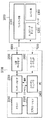
図2は、本発明の実施形態における図1に記載のプリンタ1000を示すブロック図である。
FIG. 2 is a block diagram showing the
また、図3は、本発明の実施形態における図1記載ローカルPC2000またはクライアント1のPC4000で動作するソフトウェアの構成を、ローカルPC2000を代表にして示したブロック図である。
FIG. 3 is a block diagram showing the configuration of software operating on the
以下、図2および図3を使って、本実施形態におけるプリンタとその印刷動作の大まかな流れを説明する。 Hereinafter, the general flow of the printer and its printing operation in the present embodiment will be described with reference to FIGS.
本実施形態におけるプリンタ1000は、主にコントローラ部1100、ネットワークインタフェースカード(以下NIC)1200、および、エンジン部1300からなる。
The
プリンタ1000は、印刷イメージのレンダリングや印刷制御が、ローカルPC2000、または、クライアント1のPC4000やクライアント2のPC5000などのコンピュータ上で動作することを前提に設計されている。より詳しく書くと、印刷イメージのレンダリングや印刷制御は、図3に記載されているドライバ2200やランゲージモニタ2300で実行される。このため、コントローラ部1100は、CPU1110、ASIC1120、SDRAM1130、EEPROM1140、USBコネクタ1150のみを有する。
The
CPU1110は、レンダリングや印刷制御を自らが行うプリンタに比べて極めて少ない容量のROM1111やRAM1112と、エンジン部1300とのシリアル通信を行うためのシリアルコントローラ1113を内蔵している。ROM1111には、各種制御プログラムや各種初期値が格納されている。また、RAM1112には、ワークエリアのほか、コントローラ部1100が扱う画像データを除くデータを格納するための領域が用意される。RAM1112は、揮発性RAMであるため、電源がOFFされても保持しなければならない各種カウンタ値などの限られた情報は、EEPROM1140に格納される。
The
ASIC1120は、CPUインタフェース(I/F)1121、画像処理部1122、メモリコントローラ1123、USBコントローラ1124、NICコントローラ1125をひとつにまとめたパッケージである。例えば、ローカルPC2000上のアプリケーション2100で印刷処理が実行されると、ドライバ2200が起動され、印刷用のイメージデータが生成される。
The
なお、本実施形態におけるプリンタ1000は、後述するように、アプリケーション2100による印刷に対する走査線の副走査方向のデジタル補正処理をドライバ2200において行う。
Note that the
生成されたイメージデータは、ランゲージモニタ2300に渡される。ランゲージモニタ2300は、印刷を制御するための各種コマンドと生成されたイメージデータを予め定められたプロトコルに基づき、USBポートモニタ2500およびUSBケーブル6000を経由してプリンタ1000に転送する。
The generated image data is passed to the
プリンタ1000では、転送されたコマンドやデータが、USBケーブル6000とUSBコネクタ1150を介してUSBコントローラ1124で受信される。CPU1110では、CPUインタフェース(I/F)1211 を介してUSBコントローラ1125の状態を常に監視している。
In the
もし、コマンドが受信されていたならば、コマンドに応じた処理を実行する。もし応答が必要なコマンドであれば、CPU1110は、CPUインタフェース(I/F)1121を介してUSBコントローラ1125を制御して、その応答ステータスデータをローカルPC2000に返送する。返送されたステータスは、USBケーブル6000およびUSBポートモニタ2500を介してランゲージモニタ2300に渡され、その内容はさらにステータスウィンドウ2400に通知される。ステータスウィンドウ2400は、通知されたステータスに応じて適宜プリンタや印刷の状況をローカルPC2000の表示部に表示する。
If a command has been received, processing corresponding to the command is executed. If the command requires a response, the
CPU1110がレンダリングされた印刷イメージを転送するためのコマンドを受信したときは、USBコントローラ1124およびメモリコントローラ1123を制御して、コマンドに続くイメージデータをSDRAM1130に格納させる。
When the
ある程度のイメージデータがSDRAM1130に格納されると、ランゲージモニタ2300は、エンジン部1300の起動要求コマンドを発行する。同コマンドをCPU1110が認識したならば、シリアルコントローラ 1113を制御してエンジン部1300に起動の要求を通知する。エンジン部1300が正常に起動され、用紙の搬送が正しく行われたことが、シリアルコントローラ1113を介して通知されたならば、CPU1110は、メモリコントローラ1123および画像処理部1122を制御する。さらに、SDRAM1130に格納されたイメージデータをエンジン部1300が実際の印刷動作で必要とするビデオ信号に変換して、エンジン部1300に送出する。
When a certain amount of image data is stored in the
ここで、エンジン部1300は、CPU1310、シリアルコントローラ1320、ビデオ(VIDEO)制御部1330、SDRAM1340、FLASH ROM1350、および、記録部1360を有する。CPU1310は、エンジン部全体の動作を制御する。ビデオ制御部1330は、コントローラ部1100から送られてくるビデオ信号を受ける。SDRAM1340は、ワークエリアや各種状態を示す値を保持するエリアを有する。FLASH ROM1350は、CPU1310で実行されるプログラムや参照される各種テーブル値などを格納する。記録部1360は、紙搬送系やトナー補給系、レーザビーム制御系、中間転写系、定着器系などからなる。
Here, the engine unit 1300 includes a
CPU1310は、コントローラ部1100から記録部1360の起動要求や用紙搬送要求を受けたならば、記録部1360を適宜制御し、必要に応じて状態をコントローラ部1100に通知する。もし画像形成が開始されたならば、ビデオ(VIDEO)制御部1330を制御して、コントローラ部1100から渡されたビデオ信号を記録部1360に供給して画像を形成させる。
When the
本発明に係る色ずれを測定して補正するためのレジストレーション補正用パターン画像も、コントローラ部1100とエンジン部1300との間の制御は基本的に上記と同様である。コントローラ部1110は印刷する画像を表すビデオ信号の代わりに(シアン、マゼンタ、イエロー、黒色の)レジストレーション補正用パターン画像を表すビデオ信号を転送する。エンジン部1300は、記録部1360に用意されたレジストレーション補正用パターン画像の読み取りセンサで、上記ビデオ信号によって中間転写系に形成された上記パターン画像の各色のエッジを検出する。続けて、予め定められた基準色に対する他色の主走査および走査線の副走査のずれ量を演算して、その結果をコントローラ部1100に返送する。本実施形態における画像形成装置ではシアン、マゼンタ、イエロー、黒色のうち黒色を基準色とする。しかし、基準色は本発明の本質に直接関係なく、どの色であっても良い。
The registration correction pattern image for measuring and correcting color misregistration according to the present invention is basically the same as the control described above between the
なお、本実施形態におけるプリンタ1000は、後述するように、レジストレーション補正用パターン画像に対する走査線の副走査方向のデジタル補正処理をランゲージモニタ2300において行う。
Note that the
一方、色ずれ補正に関する演算処理等の詳細は公知の電子写真系エンジンと同様で、処理そのものは本発明の本質と関係が少ないため、より詳細な説明は割愛する。 On the other hand, the details of the arithmetic processing relating to the color misregistration correction are the same as those of a known electrophotographic engine, and the processing itself has little relation to the essence of the present invention, so a more detailed description is omitted.
また、図3に記載されているステータスウィンドウ2400は、印刷の一時停止やキャンセルといったユーザの操作要求を受けることが可能であり、その操作要求は適宜ランゲージモニタ2300に伝えられる。ランゲージモニタ2300は、伝えられた操作要求に応じたコマンドを上記定められたプロトコルに基づいてUSBポートモニタ2500およびUSBケーブル6000を経由してプリンタ1000に転送する。これにより、上記のごとくコントローラ部1100によって転送されたコマンドに応じた処理が実行される。
Further, the
一方、NIC1200は、CPU1210、コントローラ通信部1220、SDRAM1230、FLASH ROM1240、および、ネットワーク通信部1250を有する。CPU1210は、NIC全体の動作を制御する。コントローラ通信部1220は、コントローラ部1100との通信を制御する。SDRAM1230は、ワークエリアや各種状態を示す値を保持するエリアを有する。FLASH ROM1240は、CPU1210で実行されるプログラムや参照される各種テーブル値などを格納する。ネットワーク通信部1250は、TCP/IPに基づいたネットワーク通信全体を制御する。
On the other hand, the
NIC1200の役割のひとつは、クライアント1のPC4000やクライアント2のPC5000などと、コントローラ部1100との仲介を行うことである。各クライアントでは、ローカルPC2000上のドライバ2200やランゲージモニタ2300と全く同一のソフトウェアに加え、USBポートモニタ2500の代わりにネットワークポートモニタ2600が動作している。ランゲージモニタ2300から発行される各種コマンドやイメージデータは、ネットワークポートモニタ2600およびネットワーク7000を介してNIC1200に伝えられる。NIC1200がネットワーク通信部1250で受けたコマンドは、コントローラ通信部1220を制御することでコントローラ部1100に渡される。コントローラ部1100は、USBコントローラ1124と同じようにNICコントローラ1125も常に監視している。上記USBの場合と同様に受信したコマンドを処理し、必要に応じてNICコントローラ1125を介してステータスデータをNIC1200に返す。NIC1200は、コントローラ通信部1220で受け取ったステータスデータを、ネットワーク通信部1250を制御してコマンド発行元のクライアントに返送する。返送されたステータスは、上記USBの場合と同様に、ランゲージモニタ2300からステータスウィンドウ2400に渡され、適宜表示される。イメージデータのやりとりも上記USBの場合と同様である。
One of the roles of the
NIC1200のもうひとつの役割は、RFC−1305で公知のNTPに基づいてNTPサーバ3000にアクセスして時刻情報を取得し、さらにその内容をコントローラ部1100にコマンドとして伝えることである。NTPサーバ3000のアドレスは、NIC1200が実装しているウェブサーバ起動の設定することができる。設定されたアドレス情報はFLASH ROM1240上に格納され、電源がOFFされても保持される。なお、TCP/IP制御やNTP処理は公知のもので本発明と直接関係ないため、より詳細な説明は割愛する。
Another role of the
図4は、図3記載のアプリケーション2100による印刷に対する走査線の副走査方向のデジタル補正に係るブロックとそれぞれの処理との関係を示す図である。 FIG. 4 is a diagram showing a relationship between blocks related to digital correction in the sub-scanning direction of the scanning line for printing by the application 2100 shown in FIG. 3 and respective processes.
図3に記載されているコントローラ部1100は、エンジン部1300から、あるタイミングiに測定されたi番目の曲がりおよび傾きの情報を予め取得し、図2に記載されているRAM1112上にキャッシュしておく。
The
図3に記載されているアプリケーション2100を使ってユーザが印刷を実行すると、OS上にドライバ2200がロードされ、アプリケーション2100からドライバ2200へ印刷要求が送られる。
When the user executes printing using the application 2100 illustrated in FIG. 3, the
ドライバ2200は、印刷要求に基づいて、レンダリング処理を実行する。
The
続いて、ドライバ2200は、ランゲージモニタ2300を介して、コントローラ部1100にキャッシュされているi番目の曲がりおよび傾きの情報を取得する。
Subsequently, the
ここで、本実施形態におけるレーザビームの曲がりおよび機構的な傾きは、上記曲がりおよび傾き情報から2次曲線(f(x)=ax2+bx+c)にフィッティングできるものとする。 Here, it is assumed that the bending and the mechanical inclination of the laser beam in the present embodiment can be fitted to a quadratic curve (f (x) = ax 2 + bx + c) from the bending and inclination information.
ドライバ2200は、曲がりおよび傾きの情報から上記2次曲線を求め、続いて、後述するように、直線近似を行う。
The
ここで、本実施形態におけるレーザスキャナユニットは、主走査幅がA4短辺の210mmに対して走査線の副走査方向の曲がりおよび傾きf(x)は、必ず1mm未満の範囲に収まるように生産されるものとする。すなわち、背景技術の項で説明したように、32画素単位で直線近似を行っても、走査線の副走査方向の誤差は用紙上に印刷されたとき目視では認識できない範囲に収まる。 Here, the laser scanner unit according to the present embodiment is produced so that the bending and the inclination f (x) in the sub-scanning direction of the scanning line are always within a range of less than 1 mm with respect to the main scanning width of 210 mm with the A4 short side. Shall be. That is, as described in the background art section, even if linear approximation is performed in units of 32 pixels, the error in the sub-scanning direction of the scanning line falls within a range that cannot be visually recognized when printed on paper.
さらにドライバ2200は、後述するように、直線近似の結果に基づいて、走査線の副走査方向に、ラインの乗り換え処理を行う。
Further, as will be described later, the
走査線の副走査方向へのラインの乗り換え処理が完了したデータは、ドライバ2200から、ランゲージモニタ2300およびコントローラ部1100を介して、エンジン部1300に転送される。
Data for which the line transfer process in the sub-scanning direction of the scanning lines is completed is transferred from the
エンジン部1300は、図2および図3の説明の通り、ビデオ信号として供給された乗換え後の画像データを記録部1360で用紙上に形成する。
As described with reference to FIGS. 2 and 3, the engine unit 1300 forms image data after transfer supplied as a video signal on a sheet by the
図5は、レジストレーション補正用パターン画像に対する走査線の副走査方向のデジタル補正に係るブロックとそれぞれの処理との関係を示す図である。 FIG. 5 is a diagram showing a relationship between a block relating to digital correction in the sub-scanning direction of the scanning line with respect to the registration correction pattern image and respective processes.
ここでは、エンジン部1300に装着されている感光ドラム一体型のトナーカートリッジが交換された場合を例にする。もちろん所定枚数(例えば100枚)の画像形成毎にこの処理を行なっても良い。 Here, the case where the photosensitive drum integrated toner cartridge mounted on the engine unit 1300 is replaced is taken as an example. Of course, this processing may be performed every time a predetermined number (for example, 100) of images is formed.
コントローラ部1100は、図4の説明と同様に、エンジン部1300から、あるタイミングiに測定されたi番目の曲がりおよび傾きの情報を予め取得し、図2に記載されているRAM1112上にキャッシュしておく。
Similarly to the description of FIG. 4, the
カートリッジが交換されると、エンジン部1300から、コントローラ部1100を介して、ランゲージモニタ2300に、曲がりおよび傾きの再測定の要求が通知される。
When the cartridge is exchanged, the engine unit 1300 notifies the
再測定の要求を受けたランゲージモニタ2300は、コントローラ部1100にキャッシュされているi番目の曲がりおよび傾きの情報を取得する。
The language monitor 2300 that has received the re-measurement request acquires the i-th curve and tilt information cached in the
続いて、ランゲージモニタ2300は、図4に記載されているドライバ2200と同様に、曲がりおよび傾きの情報を2次曲線にフィッティングする。
Subsequently, the
さらに、ランゲージモニタ2300は、直線近似の処理を行う。ここで、図4に記載されているドライバ2200における直線近似は32画素単位であったのに対して、2画素単位で、後述するように、直線近似を行う。
Further, the
引き続き、ランゲージモニタ2300は、予め用意されたレジストレーション補正用パターン画像の原画データを読み込み、走査線の副走査方向へのラインの乗り換え処理を行う。なお、レジストレーション補正用パターン画像の原画データは、例えば、1画素当たり4ビットである。
Subsequently, the
直線近似を2画素単位で行う目的は、後段の走査線の副走査方向へのラインの乗り換え処理でビット操作を回避するためである。すなわち、レジストレーション補正用パターン画像の原画データを1画素当たり4ビットで構成してあるので、ラインの乗り換え処理は必ず4×2=8ビット=1バイト境界で実施できる。これによって、扱う画素単位を小さくしたことによるラインの乗り換え処理時間の増加を少なくすることができる。なお、走査線の副走査方向へのラインの乗り換え処理の詳細は後述する。 The purpose of performing linear approximation in units of two pixels is to avoid bit manipulation in the line transfer process in the sub-scanning direction of the subsequent scanning line. That is, since the original image data of the registration correction pattern image is composed of 4 bits per pixel, line transfer processing can always be performed at 4 × 2 = 8 bits = 1 byte boundary. As a result, it is possible to reduce an increase in line transfer processing time due to a reduction in the pixel unit to be handled. Details of the line transfer process in the sub-scanning direction of the scanning lines will be described later.
走査線の副走査方向へのラインの乗り換え処理が完了したパターン画像の原画データは、ランゲージモニタ2300から、コントローラ部1100を介して、エンジン部1300に転送される。
The original image data of the pattern image for which the line transfer process in the sub-scanning direction of the scanning lines has been completed is transferred from the
エンジン部1300は、図2および図3の説明の通り、ビデオ信号として供給された乗換え後のパターン画像を記録部1360で中間転写系上に形成する。
As described with reference to FIGS. 2 and 3, the engine unit 1300 forms the pattern image after transfer supplied as a video signal on the intermediate transfer system by the
続いて、エンジン部1300は、中間転写系に形成されたレジストレーション補正用パターン画像の各色のエッジを検出し、各色の曲がりおよび傾き量を演算して求める。さらに、求めた曲がりおよび傾きの情報をコントローラ部1100に返送する。
Subsequently, the engine unit 1300 detects an edge of each color of the registration correction pattern image formed in the intermediate transfer system, and calculates and obtains a bend and an inclination amount of each color. Further, the obtained bending and tilt information is returned to the
コントローラ部1100では、返送された曲がりおよび傾きの情報を、タイミングi+1に測定されたi+1番目の曲がりおよび傾きの情報として、図2に記載されているRAM1112上にキャッシュする。
The
図6は、図4および図5に記載されている直線近似の処理を詳細に示したフローチャートである。図6に示されているフローチャートの各ステップの処理は、CPU1110によって実行される。ここで、図6に示されているフローチャートの各ステップの処理が、CPU1110以外のCPUによって実行されても良い。
FIG. 6 is a flowchart showing in detail the straight-line approximation process described in FIGS. 4 and 5. The processing of each step in the flowchart shown in FIG. 6 is executed by the
直線近似の処理はサブルーチンで、呼び出し側から画素単位wをパラメータとして受け取る。 The straight-line approximation process is a subroutine, and the pixel unit w is received as a parameter from the calling side.
まず、ステップS601において、主走査方向の位置xと配列のインデックスiを初期化する。 First, in step S601, a position x in the main scanning direction and an array index i are initialized.
以下、ステップS602において、図4および図5に記載されているフィッティングで得られた2次曲線f(x)に対してx−中央位置を与え、その四捨五入値を配列y[i]に代入する。 Hereinafter, in step S602, the x-center position is given to the quadratic curve f (x) obtained by the fitting described in FIGS. 4 and 5, and the rounded value is substituted into the array y [i]. .
また、ステップS603において、主走査方向の位置xを画素単位wだけ進め、また、配列のインデックスiをインクリメントする。 In step S603, the position x in the main scanning direction is advanced by the pixel unit w, and the array index i is incremented.
ステップS604では、xが画像幅を超えたか否かを判定する。まだ画像幅に達していなければ、ステップS602を繰り返す。 In step S604, it is determined whether x exceeds the image width. If the image width has not yet been reached, step S602 is repeated.
もし画像幅に達しているならば、ステップS605に進み、画像末尾の直線近似を行う。 If the image width has been reached, the process advances to step S605 to perform linear approximation at the end of the image.
最後にステップS606で、後段の走査線の副走査方向へのラインの乗り換え処理に、画素単位wと配列y[i]とを渡す準備をして、直線近似の処理を終了する。 Finally, in step S606, preparation for passing the pixel unit w and the array y [i] to the line transfer process in the sub-scanning direction of the subsequent scanning line is completed, and the linear approximation process ends.
図7は、図4および図5に記載されている走査線の副走査方向へのラインの乗り換え処理を詳細に示したフローチャートである。図7に示されているフローチャートの各ステップの処理は、CPU1110によって実行される。ここで、図7に示されているフローチャートの各ステップの処理が、CPU1110以外のCPUによって実行されても良い。
FIG. 7 is a flowchart showing in detail the line transfer process in the sub-scanning direction of the scanning lines described in FIGS. 4 and 5. The processing of each step in the flowchart shown in FIG. 7 is executed by the
まず、ステップS701において、図6のステップS606から引き継がれる画素単位wと、画像データの1画素当たりのビット数(depth)とから、srcおよびdstの処理単位を決定する。例えば、w=32,depth=2であれば、処理単位は8バイトになる。 First, in step S701, the src and dst processing units are determined from the pixel unit w inherited from step S606 in FIG. 6 and the number of bits per pixel of the image data (depth). For example, if w = 32 and depth = 2, the processing unit is 8 bytes.
次に、ステップS702において、主走査方向の位置xと配列のインデックスiを初期化する。 In step S702, a position x in the main scanning direction and an array index i are initialized.
以下、ステップS703では、srcの位置に対して、主走査方向には同じ位置であって、かつ、走査線の副走査方向に−y[i]ラインだけずれた位置にdstを設定する。 In step S703, dst is set to a position that is the same position in the main scanning direction as the position of src and is shifted by −y [i] lines in the sub-scanning direction of the scanning lines.
続いて、ステップS704では、srcの位置の内容をdstの位置に処理単位分コピーする。ここでは、例えば、処理単位に応じて、一度に扱うデータサイズを適宜調整し、可能な限り早くコピーできるようにすることができる。 Subsequently, in step S704, the content of the position of src is copied to the position of dst for the processing unit. Here, for example, it is possible to appropriately adjust the data size handled at a time according to the processing unit so that copying can be performed as soon as possible.
また、ステップS705において、主走査方向の位置xを画素単位wだけ進め、また、配列のインデックスiをインクリメントする。 In step S705, the position x in the main scanning direction is advanced by the pixel unit w, and the array index i is incremented.
ステップS706では、xが画像幅を超えたか否かを判定する。まだ画像幅に達していなければ、ステップS703を繰り返す。 In step S706, it is determined whether x exceeds the image width. If the image width has not yet been reached, step S703 is repeated.
もし画像幅に達しているならば、ステップS707に進み、ステップS703と同様にsrcの位置に対してdstの位置を設定する。 If the image width has been reached, the process advances to step S707 to set the dst position with respect to the src position in the same manner as in step S703.
さらに、ステップS708において、端数のコピーを行い、走査線の副走査方向のsrcの1ライン分の乗り換え処理を終了する。 Further, in step S708, the fractional copy is performed, and the transfer process for one line of src in the sub-scanning direction of the scanning line is completed.
図4および図5に記載されている走査線の副走査方向へのラインの乗り換え処理においては、すべてのsrcラインを処理するように、図7に記載されている処理を繰り返し実行する。 In the line transfer process in the sub-scanning direction of the scanning lines shown in FIGS. 4 and 5, the process shown in FIG. 7 is repeatedly executed so as to process all the src lines.
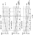
図8は、図6および図7に記載されている処理を実行したときのイメージ図で、かつ、32画素単位と2画素単位でのラインの乗り換え処理の相違例である。 FIG. 8 is an image diagram when the processing described in FIGS. 6 and 7 is executed, and is an example of a difference in line transfer processing in units of 32 pixels and units of 2 pixels.
図8の上段の図は、二点鎖線の直線がそのままエンジン部1300で画像形成された場合に、実線がどのように再現されるかを示す。すなわち、曲がりおよび傾きの様子そのものを示している。 The upper diagram in FIG. 8 shows how a solid line is reproduced when an image is formed by the engine unit 1300 as it is with a two-dot chain line. That is, the state of bending and tilting itself is shown.
図8の中段の図は、32画素単位で直線近似および走査線の副走査方向へのラインの乗り換え処理を行った場合の例である。32画素単位で直線近似して、それに基づいて、図8の上段の図の二点鎖線の直線についてラインの乗り換え処理をすると、図8の中段の図の二点鎖線の直線のようになる。ラインの乗り換え処理の主走査方向の幅が、32画素単位のときは左から順に32,32,64,64画素であったのに対し、2画素単位のときは30,34,42,76画素に変化していることがわかる。その直線をエンジン部1300で画像形成すると、実線のようになる。実線は、±1ライン未満に収まっていることがわかる。 The middle diagram of FIG. 8 is an example in the case of performing linear approximation and line transfer processing in the sub-scanning direction of the scanning line in units of 32 pixels. When a straight line approximation is performed in units of 32 pixels, and line transfer processing is performed on the two-dot chain line in the upper diagram of FIG. 8 based on the approximation, a two-dot chain line in the middle diagram of FIG. 8 is obtained. When the width of the line transfer process in the main scanning direction is 32, 32, 64, 64 pixels from the left when the unit is 32 pixels, it is 30, 34, 42, 76 pixels when the unit is 2 pixels. You can see that it has changed. When the engine unit 1300 forms an image of the straight line, a solid line is obtained. It can be seen that the solid line is within ± 1 line.
一方、図8の下段の図は、2画素単位で直線近似および走査線の副走査方向へのラインの乗り換え処理を行った場合の例である。図8の中段と同様に、2画素単位で直線近似して、それに基づいて、図8の上段の図の二点鎖線の直線について、ラインの乗り換え処理をすると、図8の中段の図の二点鎖線の直線のようになる。その直線をエンジン部1300で画像形成すると、実線のようになる。実線は、ほぼ理想通り、600dpiの解像度で±0.5ライン以下のずれに収まっていることがわかる。 On the other hand, the lower part of FIG. 8 is an example in the case of performing line approximation processing in the sub-scanning direction of the scanning line and the linear approximation in units of two pixels. Similar to the middle stage of FIG. 8, a straight line approximation is performed in units of two pixels, and based on this, when the line transfer process is performed for the straight line of the two-dot chain line in the upper part of FIG. 8, two lines in the middle part of FIG. It looks like a dotted line. When the engine unit 1300 forms an image of the straight line, a solid line is obtained. It can be seen that the solid line is within an ideal deviation of ± 0.5 lines or less at a resolution of 600 dpi as almost ideal.
ここで、図に示す位置にレジストレーション補正用パターン画像の読み取りセンサが配置されていたとする。このとき、図8の中段の図では○印の位置、図8の下段の図では◇印の位置で実線が検出される。この差はちょうど1ライン分に相当する。すなわち、32画素単位と2画素単位とでは、色ずれ量測定誤差が1ラインになる場合があり、2画素単位のほうがより理想に近いことが示されている。 Here, it is assumed that a registration correction pattern image reading sensor is arranged at the position shown in the figure. At this time, a solid line is detected at the position of the circle in the middle diagram of FIG. 8 and at the position of the ◇ in the lower diagram of FIG. This difference corresponds to exactly one line. That is, in 32 pixel units and 2 pixel units, the color misregistration amount measurement error may be one line, indicating that the 2 pixel unit is closer to the ideal.
<その他の実施形態>
第1の実施形態では、印刷イメージのレンダリングや印刷制御を、ローカルPC2000などの情報処理端末上で実行する、いわゆるホストベースのプリンティングシステムを例に本発明を説明した。しかし、本発明はホストベースのプリンティングシステムに限定されるものではない。すなわち、情報処理端末からページ記述言語で記述された命令を受け、その命令に基づいて印刷イメージをレンダリングして印刷を行う画像形成装置にも本発明を適用することができる。
<Other embodiments>
In the first embodiment, the present invention has been described by taking a so-called host-based printing system as an example in which print image rendering and print control are executed on an information processing terminal such as the
また、第1の実施形態では、アプリケーションによる印刷の場合、直線近似および走査線の副走査方向へのラインの乗り換え処理の主走査単位を32画素にして説明した。しかし、32画素単位である必要はない。例えば、レーザスキャナユニットの曲がりおよび機構的な傾き成分が、500μm未満で生産できるならば、64画素単位でも用紙上の印刷結果に与える影響は第1の実施形態と同程度になる。 In the first embodiment, in the case of printing by an application, the main scanning unit of the line approximation process in the straight line approximation and the scanning line in the sub-scanning direction has been described as 32 pixels. However, it is not necessary to be in units of 32 pixels. For example, if the bending and mechanical tilt components of the laser scanner unit can be produced at less than 500 μm, the influence on the printing result on the paper is about the same as in the first embodiment even in units of 64 pixels.
また、第1の実施形態では、レジストレーション補正用パターンの画像形成において、直線近似および走査線の副走査方向へのラインの乗り換え処理の主走査単位を2画素にして説明した。これは、第1の実施形態でも説明した通り、レジストレーション補正用パターン画像の原画データを1画素当たり4ビットで構成して、ラインの乗り換え処理を4×2=8ビット=1バイト単位で行えるようにするためである。しかし、パターン画像の原画データを1画素当たり4ビットで構成することは本発明の本質とは直接関係ない。また、同様に直線近似および走査線の副走査方向へのラインの乗り換え処理の主走査単位が2画素である必要もない。上記パターン画像の走査線の副走査方向のデジタル補正処理は、印刷ほどのパフォーマンスを要求されないので、1画素単位で処理するように構成すれば、より精度の高い色ずれ量の測定が実行できる。 In the first embodiment, in the image formation of the registration correction pattern, the main scanning unit for the line approximation process in the sub-scanning direction of the linear approximation and the scanning line has been described as two pixels. As described in the first embodiment, the original image data of the registration correction pattern image is composed of 4 bits per pixel, and line transfer processing can be performed in units of 4 × 2 = 8 bits = 1 byte. It is for doing so. However, it is not directly related to the essence of the present invention that the original image data of the pattern image is composed of 4 bits per pixel. Similarly, it is not necessary that the main scanning unit of the line approximation process in the linear approximation and the scanning line in the sub-scanning direction is two pixels. Since the digital correction processing in the sub-scanning direction of the scanning lines of the pattern image does not require performance as high as printing, if the processing is performed in units of one pixel, it is possible to measure the amount of color shift with higher accuracy.
さらに、第1の実施形態では、レーザスキャナユニットの曲がりおよび機構的な傾き成分が2次曲線f(x)でフィッティングできることを前提に説明した。しかしながら、本発明は、レーザスキャナユニットの曲がりおよび機構的な傾き成分が2次曲線でなくても適用できる。例えば、曲がり成分がなく傾き成分だけ、すなわちf(x)=ax+bの場合であっても、図6に記載されている直線近似、および、図7に記載されている走査線の副走査方向へのラインの乗り換え処理で、本発明の効果を十分得ることができる。 Furthermore, the first embodiment has been described on the assumption that the bending and mechanical inclination components of the laser scanner unit can be fitted with a quadratic curve f (x). However, the present invention can be applied even if the bending and mechanical tilt components of the laser scanner unit are not quadratic curves. For example, even when there is no bending component and only an inclination component, that is, f (x) = ax + b, the linear approximation shown in FIG. 6 and the scanning line shown in FIG. 7 in the sub-scanning direction. The effect of the present invention can be sufficiently obtained by this line transfer process.
なお、本発明では、主走査方向を区別するために、「第1の主走査方向」、「第2の主走査方向」と呼んでも良い。 In the present invention, in order to distinguish the main scanning direction, they may be referred to as “first main scanning direction” and “second main scanning direction”.
また、本発明では、デジタル補正を区別するために、「第1のデジタル補正」、「第2のデジタル補正」と呼んでも良い。 In the present invention, in order to distinguish digital correction, it may be referred to as “first digital correction” or “second digital correction”.
[その他の実施形態]
本発明は、さらに、複数の機器(例えばコンピュータ(情報処理装置)、インターフェース機器、リーダ、プリンタ等)から構成されるシステムに適用することも、一つの機器からなる装置(複合機、プリンタ、ファクシミリ装置等)に適用することも可能である。
[Other Embodiments]
The present invention can also be applied to a system composed of a plurality of devices (for example, a computer (information processing device), an interface device, a reader, a printer, etc.) or a device composed of a single device (multifunction device, printer, facsimile). It is also possible to apply to an apparatus etc.
また本発明の目的は、上述した実施形態で示したフローチャートの手順を実現するプログラムコードを記憶した記憶媒体から、システムあるいは装置のコンピュータ(またはCPUやMPU)が、そのプログラムコードを読出し実行することによっても達成される。この場合、記憶媒体から読み出されたプログラムコード自体が上述した実施形態の機能を実現することになる。そのため、このプログラムコード及びプログラムコードを記憶/記録したコンピュータ読み取り可能な記憶媒体も本発明の一つを構成することになる。 Another object of the present invention is that a computer (or CPU or MPU) of a system or apparatus reads and executes the program code from a storage medium that stores the program code that realizes the procedure of the flowchart shown in the above-described embodiment. Is also achieved. In this case, the program code itself read from the storage medium realizes the functions of the above-described embodiment. Therefore, the program code and a computer-readable storage medium storing / recording the program code also constitute one aspect of the present invention.
プログラムコードを供給するための記憶媒体としては、例えば、フロッピー(登録商標)ディスク、ハードディスク、光ディスク、光磁気ディスク、CD−ROM、CD−R、磁気テープ、不揮発性のメモリカード、ROMなどを用いることができる。 As a storage medium for supplying the program code, for example, a floppy (registered trademark) disk, hard disk, optical disk, magneto-optical disk, CD-ROM, CD-R, magnetic tape, nonvolatile memory card, ROM, or the like is used. be able to.
また、前述した実施形態の機能は、コンピュータが、読み出したプログラムを実行することによって実現される。また、このプログラムの実行とは、そのプログラムの指示に基づき、コンピュータ上で稼動しているOSなどが、実際の処理の一部または全部を行う場合も含まれる。 The functions of the above-described embodiments are realized by a computer executing a read program. The execution of the program includes a case where an OS or the like running on the computer performs part or all of the actual processing based on an instruction of the program.
さらに、前述した実施形態の機能は、コンピュータに挿入された機能拡張ボードやコンピュータに接続された機能拡張ユニットによっても実現することもできる。この場合、まず、記憶媒体から読み出されたプログラムが、コンピュータに挿入された機能拡張ボードやコンピュータに接続された機能拡張ユニットに備わるメモリに書き込まれる。その後、そのプログラムの指示に基づき、その機能拡張ボードや機能拡張ユニットに備わるCPUなどが実際の処理の一部または全部を行う。こうした機能拡張ボードや機能拡張ユニットによる処理によっても前述した実施形態の機能が実現される。 Furthermore, the functions of the above-described embodiments can also be realized by a function expansion board inserted into a computer or a function expansion unit connected to a computer. In this case, first, the program read from the storage medium is written in a memory provided in a function expansion board inserted into the computer or a function expansion unit connected to the computer. Thereafter, based on the instructions of the program, the CPU provided in the function expansion board or function expansion unit performs part or all of the actual processing. The functions of the above-described embodiment are also realized by processing by such a function expansion board or function expansion unit.
以上、いくつかの実施の形態について述べてきたが、本発明は上記実施形態に限定されるものではなく、本発明の趣旨に基づき種々の変形(各実施形態の有機的な組合せを含む)が可能であり、それらを本発明の範囲から排除するものではない。 As mentioned above, although several embodiment was described, this invention is not limited to the said embodiment, Based on the meaning of this invention, various deformation | transformation (The organic combination of each embodiment is included.) And are not excluded from the scope of the present invention.
本発明の様々な例と実施形態を示して説明したが、当業者であれば、本発明の趣旨と範囲は、本明細書内の特定の説明に限定されるものではない。 Although various examples and embodiments of the present invention have been shown and described, those skilled in the art will not limit the spirit and scope of the present invention to the specific description in the present specification.
1000 プリンタ
1100 コントローラ部
1110 CPU
1111 ROM
1112 RAM
1113 シリアルコントローラ
1120 ASIC
1121 CPUインタフェース(I/F)
1122 画像処理部
1123 メモリコントローラ
1124 USBコントローラ
1125 NICコントローラ
1130 SDRAM
1140 EEPROM
1150 USBコネクタ
1200 ネットワークインタフェースカード(NIC)
1210 CPU
1220 コントローラ通信部
1230 SDRAM
1240 FLASH ROM
1250 ネットワーク通信部
1300 エンジン部
1310 CPU
1320 シリアルコントローラ
1330 ビデオ制御部
1340 SDRAM
1350 FLASH ROM
2000 ローカルPC
2100 アプリケーション
2200 ドライバ
2300 ランゲージモニタ
2400 ステータスウィンドウ
2500 USBポートモニタ
2600 ネットワークポートモニタ
3000 NTPサーバ
4000 クライアント1のPC
5000 クライアント2のPC
6000 USBケーブル
7000 ネットワーク
1000
1111 ROM
1112 RAM
1113
1121 CPU interface (I / F)
1122
1140 EEPROM
1150
1210 CPU
1220
1240 FLASH ROM
1250 Network communication unit 1300
1320 Serial controller 1330
1350 FLASH ROM
2000 Local PC
2100
5000
6000
Claims (9)
前記走査線の副走査方向の位置ずれを、第1の画素単位で補正する第1のデジタル補正手段と、
前記走査線の副走査方向の位置ずれを、前記第1の画素単位より小さい第2の画素単位で補正する第2のデジタル補正手段と、
通常の印刷の画像形成のときは前記第1のデジタル補正手段が動作し、色ずれを測定して補正するためのレジストレーション補正用パターン画像の形成のときは前記第2のデジタル補正手段が動作するように制御する制御手段と
を備えることを特徴とする画像処理装置。 In an image processing apparatus for correcting a positional deviation of a scanning line in the sub-scanning direction
First digital correction means for correcting a positional deviation of the scanning line in the sub-scanning direction in units of first pixels;
Second digital correction means for correcting a positional deviation of the scanning line in the sub-scanning direction in a second pixel unit smaller than the first pixel unit;
The first digital correction unit operates during normal printing image formation, and the second digital correction unit operates during formation of a registration correction pattern image for measuring and correcting color misregistration. An image processing apparatus comprising: control means for performing control.
制御手段が、
通常の印刷の画像形成のときは、前記走査線の副走査方向の位置ずれを第1の画素単位で補正するように制御する一方、
色ずれを測定して補正するためのレジストレーション補正用パターン画像の形成のときは、前記走査線の副走査方向の位置ずれを、前記第1の画素単位より小さい第2の画素単位で補正するように制御する
ことを特徴とする画像処理装置の制御方法。 A control method in an image processing apparatus for correcting a positional deviation of a scanning line in a sub-scanning direction,
The control means
In normal printing image formation , the control is performed so as to correct the positional deviation of the scanning lines in the sub-scanning direction in units of first pixels .
When forming a registration correction pattern image for measuring and correcting color misregistration, the positional deviation in the sub-scanning direction of the scanning line is corrected in a second pixel unit smaller than the first pixel unit. A control method for an image processing apparatus, characterized by:
Priority Applications (5)
| Application Number | Priority Date | Filing Date | Title |
|---|---|---|---|
| JP2008000636A JP4942205B2 (en) | 2008-01-07 | 2008-01-07 | Image forming apparatus, image forming apparatus control method, and program |
| US12/345,523 US8098407B2 (en) | 2008-01-07 | 2008-12-29 | Image forming apparatus and correction of position shift of a scan line in a sub-scan direction |
| KR1020080136602A KR101221941B1 (en) | 2008-01-07 | 2008-12-30 | Image forming apparatus and control method for image forming apparatus |
| EP09150041.3A EP2077661B1 (en) | 2008-01-07 | 2009-01-05 | Image forming apparatus and control method and program for image forming apparatus |
| CN2009100019149A CN101482711B (en) | 2008-01-07 | 2009-01-07 | Image forming apparatus and control method |
Applications Claiming Priority (1)
| Application Number | Priority Date | Filing Date | Title |
|---|---|---|---|
| JP2008000636A JP4942205B2 (en) | 2008-01-07 | 2008-01-07 | Image forming apparatus, image forming apparatus control method, and program |
Publications (3)
| Publication Number | Publication Date |
|---|---|
| JP2009164898A JP2009164898A (en) | 2009-07-23 |
| JP2009164898A5 JP2009164898A5 (en) | 2011-02-24 |
| JP4942205B2 true JP4942205B2 (en) | 2012-05-30 |
Family
ID=40459848
Family Applications (1)
| Application Number | Title | Priority Date | Filing Date |
|---|---|---|---|
| JP2008000636A Expired - Fee Related JP4942205B2 (en) | 2008-01-07 | 2008-01-07 | Image forming apparatus, image forming apparatus control method, and program |
Country Status (5)
| Country | Link |
|---|---|
| US (1) | US8098407B2 (en) |
| EP (1) | EP2077661B1 (en) |
| JP (1) | JP4942205B2 (en) |
| KR (1) | KR101221941B1 (en) |
| CN (1) | CN101482711B (en) |
Families Citing this family (5)
| Publication number | Priority date | Publication date | Assignee | Title |
|---|---|---|---|---|
| JP5448350B2 (en) | 2008-02-22 | 2014-03-19 | キヤノン株式会社 | Image forming apparatus and image forming method |
| JP2010099885A (en) * | 2008-10-22 | 2010-05-06 | Canon Inc | Image forming device, image forming method, and image forming program |
| JP5754972B2 (en) * | 2011-02-15 | 2015-07-29 | キヤノン株式会社 | Image processing apparatus and image processing method |
| US9183633B2 (en) * | 2011-12-21 | 2015-11-10 | Panasonic Intellectual Property Management Co., Ltd. | Image processing apparatus and image processing method |
| JP2016177609A (en) * | 2015-03-20 | 2016-10-06 | セイコーエプソン株式会社 | Printing control device and printing control program |
Family Cites Families (20)
| Publication number | Priority date | Publication date | Assignee | Title |
|---|---|---|---|---|
| US4442675A (en) * | 1981-05-11 | 1984-04-17 | Soma Kurtis | Method for thermodynamic cycle |
| JP2633877B2 (en) | 1987-11-30 | 1997-07-23 | キヤノン株式会社 | Image forming device |
| JP3273810B2 (en) * | 1992-07-30 | 2002-04-15 | キヤノン株式会社 | Image forming device |
| JP3887951B2 (en) | 1998-06-11 | 2007-02-28 | コニカミノルタビジネステクノロジーズ株式会社 | Image forming apparatus |
| JP3388193B2 (en) | 1998-12-18 | 2003-03-17 | 富士通株式会社 | Image forming apparatus and image exposure apparatus |
| US6529643B1 (en) | 1998-12-21 | 2003-03-04 | Xerox Corporation | System for electronic compensation of beam scan trajectory distortion |
| JP3494064B2 (en) | 1999-03-02 | 2004-02-03 | 松下電器産業株式会社 | Color image forming equipment |
| JP3600228B2 (en) | 2002-03-01 | 2004-12-15 | 株式会社リコー | Optical scanning device and image forming apparatus |
| US7075561B2 (en) * | 2003-05-29 | 2006-07-11 | Konica Minolta Business Technologies, Inc. | Image printing apparatus and color misregistration correction method |
| JP2006162698A (en) * | 2004-12-02 | 2006-06-22 | Canon Inc | Image forming apparatus and its control method |
| US7684079B2 (en) * | 2004-12-02 | 2010-03-23 | Canon Kabushiki Kaisha | Image forming apparatus and its control method |
| JP4728649B2 (en) * | 2005-01-07 | 2011-07-20 | 株式会社リコー | Image forming apparatus, printer apparatus, facsimile apparatus and copying machine |
| JP2006292967A (en) * | 2005-04-08 | 2006-10-26 | Canon Inc | Color image forming apparatus |
| US7630100B2 (en) * | 2005-04-08 | 2009-12-08 | Canon Kabushiki Kaisha | Color image forming apparatus |
| US7344217B2 (en) * | 2005-04-15 | 2008-03-18 | Canon Kabushiki Kaisha | Image forming apparatus and its control method, and computer program and computer readable storage medium |
| JP4817727B2 (en) * | 2005-06-24 | 2011-11-16 | キヤノン株式会社 | Color image forming apparatus |
| JP4920966B2 (en) * | 2005-12-21 | 2012-04-18 | キヤノン株式会社 | Image forming apparatus |
| JP5162829B2 (en) * | 2006-01-19 | 2013-03-13 | 富士ゼロックス株式会社 | Image forming apparatus and image processing method thereof |
| US7777923B2 (en) * | 2006-07-20 | 2010-08-17 | Kabushiki Kaisha Toshiba | Optical beam scanning apparatus, image forming apparatus |
| JP5448350B2 (en) * | 2008-02-22 | 2014-03-19 | キヤノン株式会社 | Image forming apparatus and image forming method |
-
2008
- 2008-01-07 JP JP2008000636A patent/JP4942205B2/en not_active Expired - Fee Related
- 2008-12-29 US US12/345,523 patent/US8098407B2/en not_active Expired - Fee Related
- 2008-12-30 KR KR1020080136602A patent/KR101221941B1/en not_active IP Right Cessation
-
2009
- 2009-01-05 EP EP09150041.3A patent/EP2077661B1/en not_active Not-in-force
- 2009-01-07 CN CN2009100019149A patent/CN101482711B/en not_active Expired - Fee Related
Also Published As
| Publication number | Publication date |
|---|---|
| JP2009164898A (en) | 2009-07-23 |
| US8098407B2 (en) | 2012-01-17 |
| CN101482711A (en) | 2009-07-15 |
| KR101221941B1 (en) | 2013-01-15 |
| EP2077661A2 (en) | 2009-07-08 |
| CN101482711B (en) | 2011-11-09 |
| KR20090076791A (en) | 2009-07-13 |
| EP2077661B1 (en) | 2017-03-15 |
| EP2077661A3 (en) | 2010-09-22 |
| US20090174913A1 (en) | 2009-07-09 |
Similar Documents
| Publication | Publication Date | Title |
|---|---|---|
| US7859720B2 (en) | Image forming apparatus and method thereof | |
| US20100225932A1 (en) | Image forming apparatus and image forming method | |
| US9906683B2 (en) | Image processing device, image forming apparatus, method for processing image, and non-transitory recording medium | |
| US9651887B2 (en) | Image forming device, image forming method and program | |
| US20100103441A1 (en) | Image forming apparatus, image forming method, and image forming program | |
| JP4942205B2 (en) | Image forming apparatus, image forming apparatus control method, and program | |
| EP2437156B1 (en) | Alignment compensation by printer driver | |
| US7903304B2 (en) | Print control apparatus, print control method, program, and storage medium | |
| JP4891273B2 (en) | Image forming apparatus and control method thereof | |
| US8045225B2 (en) | Image forming apparatus, information processing apparatus, information processing method, and computer-readable storage medium | |
| JP5219647B2 (en) | Image forming apparatus, image forming system, and image processing method | |
| JP2009271378A (en) | Image forming apparatus, control method and program for the same, and storage medium | |
| EP3309620B1 (en) | Image forming apparatus and method for color registration correction | |
| JP5662675B2 (en) | Image forming apparatus and control method thereof | |
| JP2007279238A (en) | Image forming apparatus and image forming method | |
| JP2007074522A (en) | Color image processor and method | |
| JP2006210981A (en) | Image processor, image processing system, method and program, and medium recording image processing program | |
| JP2014135693A (en) | Image forming system, image processing apparatus, and image processing method | |
| JP2007181118A (en) | Image processing device, image processing method, color image forming device, control method thereof, and control program | |
| JP2010115801A (en) | Printing system | |
| JP2006001223A (en) | Information processing system, image processing method, printing method, and recording medium which stores program to perform image processing method | |
| JP2006074233A (en) | Image processor | |
| JP2006031370A (en) | Color image printing method, color image printing system and color image formation device | |
| JP2004192414A (en) | Apparatus and program for processing image | |
| JP2012171176A (en) | Image processing device and printing system |
Legal Events
| Date | Code | Title | Description |
|---|---|---|---|
| RD02 | Notification of acceptance of power of attorney |
Free format text: JAPANESE INTERMEDIATE CODE: A7422 Effective date: 20101106 |
|
| A521 | Request for written amendment filed |
Free format text: JAPANESE INTERMEDIATE CODE: A523 Effective date: 20110107 |
|
| A621 | Written request for application examination |
Free format text: JAPANESE INTERMEDIATE CODE: A621 Effective date: 20110107 |
|
| A977 | Report on retrieval |
Free format text: JAPANESE INTERMEDIATE CODE: A971007 Effective date: 20111027 |
|
| A131 | Notification of reasons for refusal |
Free format text: JAPANESE INTERMEDIATE CODE: A131 Effective date: 20111104 |
|
| RD13 | Notification of appointment of power of sub attorney |
Free format text: JAPANESE INTERMEDIATE CODE: A7433 Effective date: 20111216 |
|
| A521 | Request for written amendment filed |
Free format text: JAPANESE INTERMEDIATE CODE: A523 Effective date: 20111222 |
|
| A521 | Request for written amendment filed |
Free format text: JAPANESE INTERMEDIATE CODE: A821 Effective date: 20111216 |
|
| TRDD | Decision of grant or rejection written | ||
| A01 | Written decision to grant a patent or to grant a registration (utility model) |
Free format text: JAPANESE INTERMEDIATE CODE: A01 Effective date: 20120131 |
|
| A01 | Written decision to grant a patent or to grant a registration (utility model) |
Free format text: JAPANESE INTERMEDIATE CODE: A01 |
|
| A61 | First payment of annual fees (during grant procedure) |
Free format text: JAPANESE INTERMEDIATE CODE: A61 Effective date: 20120227 |
|
| R151 | Written notification of patent or utility model registration |
Ref document number: 4942205 Country of ref document: JP Free format text: JAPANESE INTERMEDIATE CODE: R151 |
|
| FPAY | Renewal fee payment (event date is renewal date of database) |
Free format text: PAYMENT UNTIL: 20150309 Year of fee payment: 3 |
|
| LAPS | Cancellation because of no payment of annual fees |