JP4939729B2 - Magnetic / non-magnetic material separation method, magnetic / non-magnetic material separation device and waste melting treatment equipment - Google Patents
Magnetic / non-magnetic material separation method, magnetic / non-magnetic material separation device and waste melting treatment equipment Download PDFInfo
- Publication number
- JP4939729B2 JP4939729B2 JP2003388518A JP2003388518A JP4939729B2 JP 4939729 B2 JP4939729 B2 JP 4939729B2 JP 2003388518 A JP2003388518 A JP 2003388518A JP 2003388518 A JP2003388518 A JP 2003388518A JP 4939729 B2 JP4939729 B2 JP 4939729B2
- Authority
- JP
- Japan
- Prior art keywords
- magnetic
- magnetic material
- drum
- separator
- slag
- Prior art date
- Legal status (The legal status is an assumption and is not a legal conclusion. Google has not performed a legal analysis and makes no representation as to the accuracy of the status listed.)
- Expired - Lifetime
Links
- 239000000696 magnetic material Substances 0.000 title claims description 124
- 238000000926 separation method Methods 0.000 title claims description 37
- 238000002844 melting Methods 0.000 title claims description 26
- 230000008018 melting Effects 0.000 title claims description 25
- 239000002699 waste material Substances 0.000 title claims description 14
- 239000002893 slag Substances 0.000 claims description 82
- 239000006148 magnetic separator Substances 0.000 claims description 63
- 239000000203 mixture Substances 0.000 claims description 47
- 230000002093 peripheral effect Effects 0.000 claims description 28
- 239000000126 substance Substances 0.000 claims description 14
- 238000005192 partition Methods 0.000 claims description 13
- 239000000463 material Substances 0.000 claims description 9
- 239000000155 melt Substances 0.000 claims description 9
- 238000007664 blowing Methods 0.000 claims description 6
- 238000004519 manufacturing process Methods 0.000 claims description 4
- 239000002184 metal Substances 0.000 description 43
- XLYOFNOQVPJJNP-UHFFFAOYSA-N water Substances O XLYOFNOQVPJJNP-UHFFFAOYSA-N 0.000 description 28
- 238000012544 monitoring process Methods 0.000 description 7
- 238000005507 spraying Methods 0.000 description 5
- 238000004056 waste incineration Methods 0.000 description 5
- 238000010586 diagram Methods 0.000 description 3
- 230000004907 flux Effects 0.000 description 3
- 238000005469 granulation Methods 0.000 description 3
- 230000003179 granulation Effects 0.000 description 3
- 230000007423 decrease Effects 0.000 description 2
- 239000002440 industrial waste Substances 0.000 description 2
- 230000000052 comparative effect Effects 0.000 description 1
- 238000001816 cooling Methods 0.000 description 1
- 238000007599 discharging Methods 0.000 description 1
- 238000000034 method Methods 0.000 description 1
- 238000012986 modification Methods 0.000 description 1
- 230000004048 modification Effects 0.000 description 1
- 239000012768 molten material Substances 0.000 description 1
- 239000010908 plant waste Substances 0.000 description 1
- 238000009736 wetting Methods 0.000 description 1
Images


Landscapes
- Processing Of Solid Wastes (AREA)
Description
本発明は、都市ごみ焼却工場や産業廃棄物焼却工場における溶融炉から排出される溶融物を水砕固化した水砕スラグから磁性物を分離する磁性・非磁性物分離方法、磁性・非磁性物分離装置及び該磁性・非磁性物分離装置を備えた廃棄物溶融処理設備に関するものである。 The present invention relates to a magnetic / non-magnetic material separation method, a magnetic / non-magnetic material, and a magnetic / non-magnetic material separation method for separating magnetic material from a granulated slag obtained by granulating and solidifying a melt discharged from a melting furnace in a municipal waste incineration plant or industrial waste incineration plant The present invention relates to a waste melting treatment facility equipped with a separation device and the magnetic / non-magnetic material separation device.
都市ごみ焼却工場や産業廃棄物焼却工場における溶融炉から発生するメタルとスラグは、ドラム型磁選機の上部からメタルとスラグの混合物を供給して、磁性物であるメタルをドラム表面に磁力で捕捉させて回収することにより、磁性物であるメタルと非磁性物であるスラグを分離していた。 Metal and slag generated from melting furnaces in municipal waste incineration plants and industrial waste incineration plants supply a mixture of metal and slag from the top of the drum type magnetic separator, and capture the magnetic metal on the drum surface by magnetic force. By collecting them, the magnetic metal and the non-magnetic slag were separated.
都市ごみ又は都市ごみ焼却灰を溶融処理した場合、溶融物として、磁性物であるメタルと非磁性物であるスラグが混合した状態で溶融炉の出口(出滓口)より排出される。このように混合状態の溶融物は、通常、溶融炉の下方部に位置した水砕水槽に落下し、水砕された後、水砕水槽内の溶融物分離コンベアで排出され、更にドラム型磁選機でメタルとスラグが分離され、スラグは土木資材(骨材等)、溶融メタルは金属資源としてリサイクルされている。 When municipal waste or municipal waste incineration ash is melt-processed, the molten metal is discharged from the outlet (unloading port) of the melting furnace in a state where the magnetic metal and the non-magnetic slag are mixed. In this way, the melt in a mixed state usually falls to a granulated water tank located in the lower part of the melting furnace, and after water granulation, is discharged by a melt separation conveyor in the water granulated water tank, and is further drum-type magnetically separated. Metal and slag are separated by the machine, slag is recycled as civil engineering materials (aggregates, etc.), and molten metal is recycled as metal resources.
しかし、溶融物分離コンベアより排出された溶融物は濡れ状態であるため(含水率約10%)、磁選機のドラム表面に水膜を形成する。そしてこの水の表面張力によりドラム表面にスラグが付着した状態を保持するため、ドラム表面の磁束密度が低下するという問題が起る。また、更にドラム表面に付着した非磁性物であるスラグが磁性物として回収されるため、磁選機での分離効率は極めて悪かった。 However, since the melt discharged from the melt separation conveyor is in a wet state (water content of about 10%), a water film is formed on the drum surface of the magnetic separator. And since the state in which the slag adhered to the drum surface is maintained by the surface tension of the water, there arises a problem that the magnetic flux density on the drum surface is lowered. Further, since the slag, which is a non-magnetic material adhering to the drum surface, is recovered as a magnetic material, the separation efficiency in the magnetic separator was extremely poor.
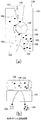
図1は従来のドラム型磁選機の概略構成を示す図である。図1(a)は側断面図、図1(b)は内部正面図である。図示するように、ドラム型磁選機100はケーシング101内に回転する回転ドラム102が配設され、該回転ドラム102の下方に仕切板103が配設され、該仕切板103で区分されたケーシング101の一方(図では右側)が磁性物排出シュート104、他方(図では左側)が非磁性物排出シュート105となっている。回転ドラム102の内部に断面扇形状の磁石106がその円弧部の外周面が回転ドラム102の内周面に接近して配設固定されている。また、ケーシング101の頂部にはメタルとスラグの混合物が投入される投入ホッパー107が設けられている。
FIG. 1 is a diagram showing a schematic configuration of a conventional drum type magnetic separator. 1A is a side sectional view, and FIG. 1B is an internal front view. As shown in the figure, the drum type
上記構成のドラム型磁選機において、投入ホッパー107に投入されたメタルとスラグの混合物110は回転している回転ドラム102の上部(この部分の回転ドラム102の内部には磁石106が位置していない)に落下する。磁性物であるメタル108の一部は落下の衝撃により、飛散し、一部は磁石106の磁力により回転ドラム102の表面に吸引され、磁石106の磁力が作用しない位置まで移動し、ここで回転ドラム102の表面から離脱し、磁性物排出シュート104に落下する。また、非磁性物であるスラグ109は非磁性物排出シュート105に落下する。
In the drum type magnetic separator having the above-described configuration, the metal and
投入ホッパー107に投入されたメタルとスラグの混合物は溶融炉から排出された後、水砕されているから濡れ状態(含水率約10%)にあるから、上記のようにドラム型磁選機100の回転ドラム102の表面に水膜を形成する。そしてこの水膜の表面張力により回転ドラム102の表面にスラグが付着した状態となるので、表面の磁束密度が低下し、更に本来、非磁性物であるスラグ109が磁性物であるメタル108が排出される磁性物排出シュート104に落下し、磁性物として回収されるため。ドラム型磁選機100での分離効率は極めて悪くなる。
本発明は、上記のように従来のドラム型磁選機で濡れ状態の磁性物であるメタルと非磁性物であるスラグの混合物を分離した場合、分離効率は極めて悪くなるという問題を解決し、濡れ状態にある磁性物と非磁性物の混合物であっても磁性物と非磁性物を効率良く分離できる磁性・非磁性物分離方法、磁性・非磁性物分離装置及び該磁性・非磁性物分離装置を備えた廃棄物溶融処理設備を提供することを目的とする。 As described above, the present invention solves the problem that the separation efficiency becomes extremely poor when a mixture of a metal that is a wet magnetic substance and a slag that is a non-magnetic substance is separated by a conventional drum type magnetic separator. Magnetic / non-magnetic material separation method, magnetic / non-magnetic material separation device, and magnetic / non-magnetic material separation device capable of efficiently separating magnetic material and non-magnetic material even in the state of a mixture of magnetic material and non-magnetic material It aims at providing the waste melting processing equipment provided with.
上記課題を解決するため請求項1に記載の発明は、ケーシング内に配置されたドラム型磁選機を具備し、ドラム型磁選機の上方に設けた投入ホッパーからドラム型磁選機に供給される溶融水砕固化された濡れ状態である磁性物と非磁性物の混合物から磁性物と非磁性物を分離する磁性・非磁性物分離方法において、ケーシング内のドラム型磁選機のドラム下方に仕切板が配置され、該仕切板で仕切られた一方側が磁性物排出シュート、他方側が非磁性物排出シュートとなっており、ケーシング内のドラム型磁選機のドラム下方に設けたノズルから、非磁性物排出シュート上方のドラム表面に圧力空気をドラムの単位長当り1〜5(m 3 /min/m)の風量にて接線方向に吹き付け、ドラム型磁選機で分離された磁性物を磁性物排出シュートに、非磁性物を非磁性物排出シュートに落下させて磁性物と非磁性物を分離することを特徴とする。 In order to solve the above-mentioned problem, the invention according to claim 1 is provided with a drum type magnetic separator disposed in a casing, and is supplied to a drum type magnetic separator from a charging hopper provided above the drum type magnetic separator. In a magnetic / non-magnetic material separation method for separating magnetic and non-magnetic materials from a mixture of magnetic and non-magnetic materials that are wet and solidified, a partition plate is provided below the drum of the drum type magnetic separator in the casing. The magnetic material discharge chute is arranged on one side and is partitioned by the partition plate, and the other side is a non-magnetic material discharge chute. From the nozzle provided below the drum type magnetic separator in the casing, the non-magnetic material discharge chute blown tangentially by the air volume above the drum unit length of the drum per pressure air to the surface 1~5 (m 3 / min / m ), magnetic matter discharge chute magnetic material separated in drum magnetic separator , Characterized in that by dropping the nonmagnetic material in the non-magnetic material discharging chute separating magnetic material and a nonmagnetic material.
請求項2に記載の発明は、請求項1に記載の磁性・非磁性物分離方法において、混合物の供給速度に応じてドラム型磁選機のドラムの周速度を変化させることを特徴とする。 According to a second aspect of the invention, in the magnetic and non-magnetic material separation process according to claim 1, characterized that you vary the circumferential speed of the drum of a drum-type magnetic separator in accordance with the feed rate of the mixture.
請求項3に記載の発明は、ケーシング内に配置されたドラム型磁選機を具備し、ドラム型磁選機の上方に設けた投入ホッパーからドラム型磁選機に供給される溶融水砕固化された濡れ状態である磁性物と非磁性物の混合物から磁性物と非磁性物を分離する磁性・非磁性物分離装置において、ケーシング内のドラム型磁選機のドラム下方に仕切板が配置され、該仕切板で仕切られた一方側がドラム型磁選機で分離された磁性物が落下する磁性物排出シュート、他方側がドラム型磁選機で分離された非磁性物が落下する非磁性物排出シュートとなっており、ケーシング内のドラム型磁選機のドラム下方に非磁性物排出シュート上方のドラム表面へドラムの接線方向にドラムの単位長当り1〜5(m 3 /min/m)の風量の圧力空気を吹き付ける圧力空気吹付手段を設けたことを特徴とする。 The invention according to claim 3 is provided with a drum type magnetic separator disposed in a casing, and is supplied with a molten pulverized and solidified wetting supplied to a drum type magnetic separator from a charging hopper provided above the drum type magnetic separator. In a magnetic / non-magnetic material separation device for separating magnetic material and non-magnetic material from a mixture of magnetic material and non-magnetic material in a state, a partition plate is disposed below the drum of the drum type magnetic separator in the casing, and the partition plate The magnetic material discharge chute on which the magnetic material separated on the one side separated by the drum type magnetic separator falls, and the other side is the nonmagnetic material discharge chute on which the nonmagnetic material separated by the drum type magnetic separator falls, blowing compressed air of the air volume of the non-magnetic material discharge chute above the drum to the surface of the drum tangentially unit length of the drum per 1~5 (m 3 / min / m ) in the drum below the drum magnetic separator in the casing Characterized in that a force air blowing device.
請求項4に記載の発明は、請求項3に記載の磁性・非磁性物分離装置において、混合物の供給速度を検出し、該検出した混合物の供給速度に応じてドラム型磁選機のドラムの回転速度を制御する制御手段を設けたことを特徴とする。 According to a fourth aspect of the present invention, in the magnetic / non-magnetic material separation device according to the third aspect, the supply speed of the mixture is detected, and the drum of the drum type magnetic separator is rotated according to the detected supply speed of the mixture. characterized in that a control means to control the speed.
請求項5に記載の発明は、廃棄物を溶融する溶融炉、該溶融炉から排出される溶融物を水砕固化した水砕スラグを製造するスラグ製造装置、該スラグ製造装置から排出された水砕スラグを磁性物と非磁性物に分離する磁性・非磁性物分離装置を備えた廃棄物溶融処理設備において、磁性・非磁性物分離装置に、請求項3又は4に記載の磁性・非磁性物分離装置を用いることを特徴とする。
The invention according to
請求項1又は3に記載の発明によれば、ドラム型磁選機のドラム下方に設けたノズルから、非磁性物排出シュート上方のドラム表面に圧力空気をドラムの単位長当り1〜5(m 3 /min/m)の風量にて接線方向に吹き付けることにより、混合物が濡れ状態でも回転ドラム表面に形成された水膜が破壊され、その表面張力が低下するから、該ドラム表面に付着した非磁性物が効率良く吹き飛ばされると共に、回転ドラム表面の磁束密度の低下もないことから、分離された磁性物への非磁性物の混入率を小さくできる。 According to the first or third aspect of the present invention, pressure air is applied to the drum surface above the non-magnetic material discharge chute from the nozzle provided below the drum of the drum type magnetic separator to 1 to 5 (m 3 per unit length of the drum). / Min / m), the water film formed on the surface of the rotating drum is destroyed even when the mixture is wet, and the surface tension is reduced. Since the material is efficiently blown away and the magnetic flux density on the surface of the rotating drum is not lowered , the mixing rate of the non-magnetic material into the separated magnetic material can be reduced.
請求項2又は4に記載の発明によれば、混合物の供給速度に応じてドラム型磁選機のドラムの周速度を変化させるので、分離された磁性物への非磁性物の混入率を更に小さくできる。
According to the invention described in
請求項5に記載の発明によれば、廃棄物溶融処理設備のスラグ製造装置から排出された水砕スラグを磁性物と非磁性物に分離する磁性・非磁性物分離装置に請求項3又は4のいずれか1項に記載の磁性・非磁性物分離装置を用いるので、廃棄物から磁性物を高効率で回収できる廃棄物溶融処理設備を提供できる。
According to the invention of
以下、本発明の実施の形態例を図面に基づいて説明する。図2は本発明に係る磁性・非磁性物分離装置のドラム型磁選機の構成例を示す図である。図2(a)は側断面図、図2(b)は内部正面図である。図示するように、ドラム型磁選機10はケーシング11内に回転する回転ドラム12が配設され、該回転ドラム12の下方に仕切板13が配設され、該仕切板13で区分されたケーシング11の一方(図では右側)が磁性物排出シュート14、他方(図では左側)が非磁性物排出シュート15となっている。回転ドラム12の内部に断面扇形状の磁石16がその円弧部の外周面が回転ドラム12の内周面に接近して配設固定されている。また、ケーシング11の頂部には溶融水砕固化されたメタルとスラグの混合物20が投入される投入ホッパー17が設けられている。また、回転ドラム12の下方には圧力空気21を噴出するエアノズル22を設け、該エアノズル22から圧力空気21を非磁性物排出シュート15側の上方で且つ回転ドラム12の表面の接線方向に噴出するようになっている。
Embodiments of the present invention will be described below with reference to the drawings. FIG. 2 is a diagram showing a configuration example of a drum type magnetic separator of the magnetic / non-magnetic material separating apparatus according to the present invention. 2A is a side sectional view, and FIG. 2B is an internal front view. As shown in the figure, the drum type
また、回転ドラム12は図3に示すように、モータ23で回転駆動されるようになっており、該モータ23はモータ駆動装置24で駆動されるようになっている。また、モータ駆動装置24には制御装置25から制御信号Sが入力され、モータ駆動装置24は該制御信号Sに基づいてモータ23を指令された回転速度で駆動するようになっている。また、制御装置25にはドラム型磁選機10に供給される溶融水砕固化されたメタルとスラグの混合物20の供給速度を検出するための各種センサ26−1〜26−nが接続されており、制御装置25は該センサ26−1〜26−nからの出力により混合物20の供給速度を演算して求め、この供給速度に応じて回転ドラム12の周速を変化させることができるようになっている。
Further, as shown in FIG. 3, the
上記構成のドラム型磁選機において、投入ホッパー17に投入されたメタルとスラグの混合物20は回転している回転ドラム12の上部に落下する。混合物20は上記のように濡れ状態(含水率約10%)にあるから、回転ドラム12の表面に水膜を形成し、水の表面張力により回転ドラム12の表面にスラグ19が付着した状態となると共に、メタル18は磁石16の磁力により回転ドラム12の表面に吸引される。回転ドラム12の表面には上記のようにその接線方向にエアノズル22から圧力空気21が吹き付けられているから、付着したスラグが吹き飛ばされて回転ドラム12の表面から離脱し、非磁性物排出シュート15に落下する。また、磁性物であるメタル18は磁石16の磁力が作用しない位置で回転ドラム12の表面から離脱し、磁性物排出シュート14に落下する。
In the drum type magnetic separator having the above-described configuration, the metal and
上記のように、回転ドラム12の表面に付着したスラグ19はエアノズル22から噴出された圧力空気21により吹き飛ばされるから、磁性物排出シュート14に落下するメタル18にはスラグ19の混入率は極めて小さくなる。また、回転ドラム12の表面に付着したスラグ19が除去されることにより、回転ドラム12の表面の磁石16による磁気吸引力が低下することなく、磁性物であるメタル18は確実に回転ドラム12の表面に吸引され、磁力が作用しない位置で離脱するから、混合物20からのメタル18の分離率が向上する。また、回転ドラム12の周速は上記のように混合物20の供給速度に応じて変化させるようになっているから、後に実験結果で示すように分離されたメタル18のスラグ混入率を低減させることができる。
As described above, since the
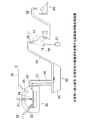
図4は本発明に係る磁性・非磁性物分離装置を使用する廃棄物溶融処理設備の全体構成例を示す図である。図示するように廃棄物溶融処理設備は、溶融炉30、スラグ分離コンベア40、スラグヤード50を具備する。溶融炉30はプラズマトーチ31を具備し、焼却灰投入口32から投入された焼却灰33をプラズマトーチ31から発せられるプラズマアーク34の高温で溶融し、出滓口35から溶融した磁性物であるメタルと非磁性物であるスラグの混合物37を排出するようになっている。焼却灰33の溶融に伴って発生するガスは排ガス39となってガス出口36から排出される。
FIG. 4 is a diagram showing an example of the overall configuration of a waste melting treatment facility using the magnetic / non-magnetic material separating apparatus according to the present invention. As shown in the figure, the waste melting treatment facility includes a melting
出滓口35から排出された混合物37はシュート38を通ってスラグ分離コンベア40の水砕水槽41内に落下する。該水砕水槽41に落下した混合物37は水砕水槽41内の水と接触し、水砕され、固化する。なお、混合物37をシュート38内で水と接触させ、水砕された混合物を水砕水槽41内に落下させる場合もある。水砕水槽41内で水砕固化した混合物20はコンベア42でドラム型磁選機10の投入ホッパー17に運ばれ投入される。ドラム型磁選機10では混合物20は、上記のように磁性物であるメタル18と非磁性物であるスラグ19に分離される。分離されたメタル18は磁性物排出シュート14から排出され、メタルバケット27に収容され、再利用される。また、分離されたスラグ19はスラグ搬送コンベア28によりスラグヤード50に運ばれる。
The
ドラム型磁選機10に供給される水砕固化されたメタルとスラグの混合物20の供給速度(t/h)を検出するための各種センサ26−1〜26−n(図3参照)としては、例えば溶融炉30の出滓口35やシュート38の近傍に、出滓口35から排出される混合物37やシュート38内を落下する混合物37を監視する監視カメラを設け、制御装置25で該監視カメラからの画像信号を画像処理し、供給される混合物20の供給速度を検出する方法がある。また、監視カメラに替えてサーモカメラを設置し、制御装置25で該サーモカメラの出力信号を処理し、混合物20の供給速度を検出するようにしてもよい。また、出滓口35やシュート38の近傍に、1個又は複数個の温度計を設け、この温度計の出力信号を処理し、混合物20の供給速度を検出するようにしてもよい。また、スラグ分離コンベア40の水砕水槽41の1又は複数箇所に水温を測定する温度計を設け、該温度計の出力信号を処理し、混合物20の供給速度を検出するようにしてもよい。
As various sensors 26-1 to 26-n (see FIG. 3) for detecting the supply speed (t / h) of the
図5は水砕水槽にて水砕冷却された混合物(メタル50%、スラグ50%)を供給速度0.5t/h、1.0t/h、2.0t/hの条件で、図2に示す構成のドラム型磁選機10に供給し、磁性物(メタル)と非磁性物(スラグ)を分離した場合の磁性物側(磁性物排出シュート14側)のスラグ混入率(%)を示す図である。この時の回転ドラム12の周速は50m/minに固定している。また、回転ドラム12の表面に下方に設置したエアノズル22から接線方向にエア(圧力空気)を吹き付けて付着したスラグを除去する場合と、エアを吹き付けない場合を示す。従来のように、エアを吹き付けない場合の磁性物側スラグ混入率が13%、18%、27%であるのに対して、エアを吹き付け、回転ドラム12の表面に付着したスラグを除去した場合の磁性物側スラグ混入率が1.6%、1.9%、2.0%となる。図から明らかなように、回転ドラム12の表面にエアを吹き付けた場合、即ち本発明によれば磁性物側スラグ混入率が大幅に改善されることがわかる。なお、このときのエア吹き付け量は、回転ドラム12の単位長当り1〜5(m 3 /min/m)吹き付け圧力は500〜1000kPaである。
FIG. 5 shows a mixture (50% metal, 50% slag) that has been subjected to water granulation cooling in a water granulation water tank under the conditions of supply speeds of 0.5 t / h, 1.0 t / h, and 2.0 t / h. The figure which shows the slag mixing rate (%) by the side of the magnetic material (magnetic
図6は上記実施例1と同様の混合物(メタル50%、スラグ50%)を供給速度0.5t/h、1.0t/h、1.5t/hの条件で図2に示す構成のドラム型磁選機10に供給し、回転ドラム12のドラム周速を変化させて磁性物(メタル)と非磁性物(スラグ)を分離した場合の磁性物側(磁性物排出シュート14側)のスラグ混入率(%)を示す図である。曲線Aが1.5t/h、曲線Bが1.0t/h、曲線Cが0.5t/hをそれぞれ示す。図示するように、ドラム周速を50m/min〜200m/minに変化させることにより、混合物の供給速度0.5t/h、1.0t/h、1.5t/hのいずれの場合もスラグ混入率が改善される。
FIG. 6 shows a drum having the same composition as in Example 1 (50% metal, 50% slag) at a feed rate of 0.5 t / h, 1.0 t / h, and 1.5 t / h as shown in FIG. Slag mixing on the magnetic material side (magnetic
図7は上記実施例1と同様の混合物(メタル50%、スラグ50%)を供給速度0.5t/h、1.0t/h、1.5t/hの条件で図2に示す構成のドラム型磁選機10に供給し、回転ドラム12の周速を変化させて磁性物(メタル)と非磁性物(スラグ)を分離した場合の磁性物側(磁性物排出シュート14側)のスラグ混入率(%)を示す図である。ここでは、回転ドラム12の表面に下方に設置したエアノズル22から接線方向に空気を吹き付けて付着したスラグを除去している。曲線Aが1.5t/h、曲線Bが1.0t/h、曲線Cが0.5t/hをそれぞれ示す。図示するように、回転ドラム12の表面に接線方向に空気を吹き付けて付着スラグを除去し、回転ドラム12の周速を速くすることにより、磁性物側のスラグ混入率が大幅に改善されることがわかる。
FIG. 7 shows a drum having the same composition as in Example 1 (50% metal, 50% slag) at a feed rate of 0.5 t / h, 1.0 t / h, and 1.5 t / h as shown in FIG. Slag mixing rate on the magnetic material side (magnetic
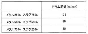
図8は混合物として、(1)メタル25%、スラグ75%、(2)メタル50%、スラグ50%、(3)メタル75%、スラグ25%の3種類の混合物を供給速度1.0t/hで図2に示す構成のドラム型磁選機10に供給し、磁性物側のスラグ混入率を1.0%以下にするための回転ドラム12の周速を求めた。(1)の場合は周速125m/min、(2)の場合は周速80m/min、(3)の場合は周速50m/minで、磁性物側のスラグ混入率が1.0%以下になる。これにより、メタルの含有率に応じてドラム型磁選機10の回転ドラム12の周速を変化させることにより磁性物側のスラグ混入率を低減させることができることがわかる。
FIG. 8 shows a mixture of (1) 25% metal, 75% slag, (2) 50% metal, 50% slag, and (3) 75% metal, 25% slag. 2 was supplied to the drum type
図9は図4に示すような構成の廃棄物溶融処理設備において、出滓口35の近傍に監視カメラを設置し、該監視カメラで溶融炉30の炉体を傾動させ炉体内に滞留している溶融物が出滓口35から排出される状態を撮影し、図3の制御装置25で該監視カメラからの画像信号を画像処理し、溶融物の排出速度を検出し、その排出速度に応じて、図3のドラム型磁選機10の回転ドラム12の周速を変化させた場合と、変化させない場合で磁性物(メタル)と非磁性物(スラグ)を分離させた場合の磁性物側のスラグ混入率を示す図である。図示するように、従来のように回転ドラム12の周速を100m/minで一定にした場合、磁性物側のスラグ混入率が26%であるのに対し、本発明のように回転ドラム12の周速を50m/min〜100m/minの範囲で可変した場合、磁性物側のスラグ混入率が3.3%と大幅に改善できる。
FIG. 9 shows a waste melting treatment facility configured as shown in FIG. 4. A monitoring camera is installed in the vicinity of the
以上本発明の実施形態を説明したが、本発明は上記実施形態に限定されるものではなく、特許請求の範囲、及び明細書と図面に記載された技術的思想の範囲内において種々の変形が可能である。例えば、図2に示すドラム型磁選機10ではドラム下方に設置したエアノズルから、回転ドラム12の表面に接線方向に圧力空気21を噴出したが、回転ドラム12の表面に付着した非磁性物であるスラグを効果的に除去できるのであれば、接線方向に限定されるものではない。また、混合物の供給速度に応じて回転ドラム周速を変えること、回転ドラム表面に圧力空気を吹き付けること、回転ドラム表面に下方から接線方向に圧力空気を吹き付けることの二つ以上を組合せて、本発明に係る磁性・非磁性物分離方法及び装置を構成してもよい。
Although the embodiments of the present invention have been described above, the present invention is not limited to the above-described embodiments, and various modifications can be made within the scope of the technical idea described in the claims and the specification and drawings. Is possible. For example, in the drum type
10 ドラム型磁選機
11 ケーシング
12 回転ドラム
13 仕切板
14 磁性物排出シュート
15 非磁性物排出シュート
16 磁石
17 投入ポッパー
18 メタル
19 スラグ
20 混合物
21 圧力空気
22 エアノズル
23 モータ
24 モータ駆動装置
25 制御装置
26 センサ
27 メタルバケット
28 スラグ搬送コンベア
30 溶融炉
31 プラズマトーチ
32 焼却灰投入口
33 焼却灰
34 プラズマアーク
35 出滓口
36 ガス出口
37 混合物
39 排ガス
40 スラグ分離コンベア
41 水砕水槽
42 コンベヤ
50 スラグヤード
DESCRIPTION OF
Claims (5)
前記ケーシング内の前記ドラム型磁選機のドラム下方に仕切板が配置され、該仕切板で仕切られた一方側が磁性物排出シュート、他方側が非磁性物排出シュートとなっており、
前記ケーシング内の前記ドラム型磁選機のドラム下方に設けたノズルから、前記非磁性物排出シュート上方の前記ドラム表面に圧力空気を前記ドラムの単位長当り1〜5(m 3 /min/m)の風量にて接線方向に吹き付け、
前記ドラム型磁選機で分離された磁性物を前記磁性物排出シュートに、非磁性物を前記非磁性物排出シュートに落下させて磁性物と非磁性物を分離することを特徴とする磁性・非磁性物分離方法。 A drum type magnetic separator disposed in a casing, and a non-magnetic material in a wet state that has been melted, crushed, solidified and supplied to the drum type magnetic separator from a charging hopper provided above the drum type magnetic separator In a magnetic / nonmagnetic separation method for separating magnetic and nonmagnetic materials from a mixture of magnetic materials,
A partition plate is disposed below the drum of the drum type magnetic separator in the casing, one side partitioned by the partition plate is a magnetic material discharge chute, the other side is a non-magnetic material discharge chute,
1 to 5 (m 3 / min / m) of compressed air per unit length of the drum from the nozzle provided below the drum of the drum type magnetic separator in the casing to the drum surface above the non-magnetic material discharge chute Sprayed tangentially with
The magnetic / non-magnetic material is separated by dropping the magnetic material separated by the drum type magnetic separator onto the magnetic material discharge chute and dropping the non-magnetic material onto the non-magnetic material discharge chute. Magnetic substance separation method.
前記混合物の供給速度に応じて前記ドラム型磁選機のドラムの周速度を変化させることを特徴とする磁性・非磁性物分離方法。 In the magnetic / nonmagnetic separation method according to claim 1,
Magnetic and non-magnetic material separating wherein a call for changing the peripheral speed of the drum of the drum-type magnetic separator in accordance with the feed rate of the mixture.
前記ケーシング内の前記ドラム型磁選機のドラム下方に仕切板が配置され、該仕切板で仕切られた一方側が前記ドラム型磁選機で分離された磁性物が落下する磁性物排出シュート、他方側が前記ドラム型磁選機で分離された非磁性物が落下する非磁性物排出シュートとなっており、
前記ケーシング内の前記ドラム型磁選機のドラム下方に前記非磁性物排出シュート上方の前記ドラム表面へ前記ドラムの接線方向に前記ドラムの単位長当り1〜5(m 3 /min/m)の風量の圧力空気を吹き付ける圧力空気吹付手段を設けたことを特徴とする磁性・非磁性物分離装置。 A drum type magnetic separator disposed in a casing, and a non-magnetic material in a wet state that has been melted, crushed, solidified and supplied to the drum type magnetic separator from a charging hopper provided above the drum type magnetic separator In a magnetic / non-magnetic material separation device that separates magnetic and non-magnetic materials from a mixture of magnetic materials,
A partition plate is disposed below the drum of the drum type magnetic separator in the casing, one side partitioned by the partition plate is a magnetic material discharge chute from which the magnetic material separated by the drum type magnetic separator falls, and the other side is the above It is a non-magnetic material discharge chute where the non-magnetic material separated by the drum type magnetic separator falls,
Air volume of 1 to 5 (m 3 / min / m) per unit length of the drum in the tangential direction of the drum to the drum surface above the non-magnetic material discharge chute below the drum of the drum type magnetic separator in the casing A magnetic / non-magnetic substance separating apparatus, characterized in that it is provided with a pressure air blowing means for blowing the pressure air.
前記混合物の供給速度を検出し、該検出した混合物の供給速度に応じて前記ドラム型磁選機のドラムの回転速度を制御する制御手段を設けたことを特徴とする磁性・非磁性物分離装置。 The magnetic / non-magnetic material separating apparatus according to claim 3,
The mixture detects the feed speed of the magnetic and non-magnetic substance separator and wherein the control means for controlling the rotational speed of the drum of the drum-type magnetic separator digits set in accordance with the feed rate of the mixture the detected.
前記磁性・非磁性物分離装置に、請求項3又は4に記載の磁性・非磁性物分離装置を用いることを特徴とする廃棄物溶融処理設備。 A melting furnace for melting waste, a slag manufacturing apparatus for manufacturing a granulated slag obtained by granulating and solidifying a melt discharged from the melting furnace, a granulated slag discharged from the slag manufacturing apparatus as a magnetic material and a non-magnetic material In a waste melting treatment facility equipped with a magnetic / non-magnetic material separation device
A waste melting treatment facility using the magnetic / non-magnetic material separation device according to claim 3 or 4 as the magnetic / non-magnetic material separation device.
Priority Applications (1)
| Application Number | Priority Date | Filing Date | Title |
|---|---|---|---|
| JP2003388518A JP4939729B2 (en) | 2003-11-18 | 2003-11-18 | Magnetic / non-magnetic material separation method, magnetic / non-magnetic material separation device and waste melting treatment equipment |
Applications Claiming Priority (1)
| Application Number | Priority Date | Filing Date | Title |
|---|---|---|---|
| JP2003388518A JP4939729B2 (en) | 2003-11-18 | 2003-11-18 | Magnetic / non-magnetic material separation method, magnetic / non-magnetic material separation device and waste melting treatment equipment |
Publications (3)
| Publication Number | Publication Date |
|---|---|
| JP2005144390A JP2005144390A (en) | 2005-06-09 |
| JP2005144390A5 JP2005144390A5 (en) | 2006-12-07 |
| JP4939729B2 true JP4939729B2 (en) | 2012-05-30 |
Family
ID=34695556
Family Applications (1)
| Application Number | Title | Priority Date | Filing Date |
|---|---|---|---|
| JP2003388518A Expired - Lifetime JP4939729B2 (en) | 2003-11-18 | 2003-11-18 | Magnetic / non-magnetic material separation method, magnetic / non-magnetic material separation device and waste melting treatment equipment |
Country Status (1)
| Country | Link |
|---|---|
| JP (1) | JP4939729B2 (en) |
Cited By (1)
| Publication number | Priority date | Publication date | Assignee | Title |
|---|---|---|---|---|
| CN109311057A (en) * | 2016-06-06 | 2019-02-05 | 新东工业株式会社 | Separator and shot-treating apparatus |
Families Citing this family (3)
| Publication number | Priority date | Publication date | Assignee | Title |
|---|---|---|---|---|
| CN102527508B (en) * | 2011-12-14 | 2014-05-28 | 柳州市远健磁力设备制造有限责任公司 | Method for recovering aluminum and iron from metal scraps produced by cutting by wet magnetic separation |
| JP2019051472A (en) * | 2017-09-14 | 2019-04-04 | 日新製鋼株式会社 | Magnetic separation method of steel-making slag, and magnetic separation device of steel-making slag |
| CN109847926A (en) * | 2019-01-11 | 2019-06-07 | 孙树春 | A kind of dry type wind magnetic separator and its application method |
Family Cites Families (6)
| Publication number | Priority date | Publication date | Assignee | Title |
|---|---|---|---|---|
| SE7309949L (en) * | 1973-07-16 | 1975-01-17 | Atomenergi Ab | SEPARATOR FOR A TREATMENT OF STEAM AND WATER. |
| JPH04131151A (en) * | 1990-09-25 | 1992-05-01 | Tohoku Electric Power Co Inc | Removing device for iron piece in bulk material |
| JPH05123605A (en) * | 1991-11-06 | 1993-05-21 | Sumitomo Metal Ind Ltd | Method for recovering ground metal contained in slag |
| JPH0985124A (en) * | 1995-09-26 | 1997-03-31 | Hitachi Zosen Corp | Magnetic force separator |
| JPH11179334A (en) * | 1997-12-19 | 1999-07-06 | Nkk Corp | Method and apparatus for collecting slag from melt of waste melting furnace |
| JP3652638B2 (en) * | 2001-11-14 | 2005-05-25 | 川崎重工業株式会社 | Slag reforming method and apparatus |
-
2003
- 2003-11-18 JP JP2003388518A patent/JP4939729B2/en not_active Expired - Lifetime
Cited By (1)
| Publication number | Priority date | Publication date | Assignee | Title |
|---|---|---|---|---|
| CN109311057A (en) * | 2016-06-06 | 2019-02-05 | 新东工业株式会社 | Separator and shot-treating apparatus |
Also Published As
| Publication number | Publication date |
|---|---|
| JP2005144390A (en) | 2005-06-09 |
Similar Documents
| Publication | Publication Date | Title |
|---|---|---|
| US4747547A (en) | Process for the treatment of slag generated in an ironworks | |
| JP2013117058A (en) | Apparatus for producing iron-based material and regenerated sand | |
| CN201046415Y (en) | Apparatus for separating and recycling granulating slag iron | |
| JP4017403B2 (en) | Sand making system | |
| JP2003145123A (en) | Method for reforming slag and device therefor | |
| JP4939729B2 (en) | Magnetic / non-magnetic material separation method, magnetic / non-magnetic material separation device and waste melting treatment equipment | |
| JP2005144390A5 (en) | ||
| EP0785028B1 (en) | Apparatus for solidifying and processing a molten material | |
| JP6374742B2 (en) | Vertical roller mill | |
| EP2297369B1 (en) | Method for recycling aluminium slags comprising an eddy current separator operating at reduced rotary speed. | |
| JP2003071405A (en) | Pretreatment method for ash fusing furnace | |
| JP3564035B2 (en) | Method and apparatus for separating and recovering metal and slag from metal-containing raw materials | |
| JP2006102663A (en) | Method for treating molten slag | |
| JP4027592B2 (en) | Empty can processing method | |
| JP3827976B2 (en) | Pretreatment method and pretreatment apparatus for ash melting furnace | |
| JPH08187485A (en) | Apparatus for treating molten matter discharged from waste melting furnace | |
| JP4526675B2 (en) | Dewatering method and dewatering equipment for slurry containing pitch particle | |
| JP2001280631A (en) | Method and device for recovering molten metal exhausted from rotary kiln | |
| JPH09137923A (en) | Solidification processor for melted matter by waste melting furnace | |
| JPH09290219A (en) | Refuse disposal facility | |
| JP4430835B2 (en) | Manufacturing method of artificial lightweight aggregate | |
| JP2006045599A (en) | Method for granulating sulfur filtration residue | |
| JP5573581B2 (en) | Waste water slag granulating apparatus and method | |
| JP3137713U (en) | Main ash pretreatment equipment | |
| JPH11179333A (en) | Method and apparatus for separating water granulated slag of waste melting furnace |
Legal Events
| Date | Code | Title | Description |
|---|---|---|---|
| A521 | Request for written amendment filed |
Free format text: JAPANESE INTERMEDIATE CODE: A821 Effective date: 20061024 Free format text: JAPANESE INTERMEDIATE CODE: A523 Effective date: 20061024 |
|
| A621 | Written request for application examination |
Free format text: JAPANESE INTERMEDIATE CODE: A621 Effective date: 20061024 |
|
| A131 | Notification of reasons for refusal |
Free format text: JAPANESE INTERMEDIATE CODE: A131 Effective date: 20100119 |
|
| A521 | Request for written amendment filed |
Free format text: JAPANESE INTERMEDIATE CODE: A523 Effective date: 20100323 |
|
| A131 | Notification of reasons for refusal |
Free format text: JAPANESE INTERMEDIATE CODE: A131 Effective date: 20110329 |
|
| A521 | Request for written amendment filed |
Free format text: JAPANESE INTERMEDIATE CODE: A523 Effective date: 20110527 |
|
| TRDD | Decision of grant or rejection written | ||
| A01 | Written decision to grant a patent or to grant a registration (utility model) |
Free format text: JAPANESE INTERMEDIATE CODE: A01 Effective date: 20120214 |
|
| A01 | Written decision to grant a patent or to grant a registration (utility model) |
Free format text: JAPANESE INTERMEDIATE CODE: A01 |
|
| A61 | First payment of annual fees (during grant procedure) |
Free format text: JAPANESE INTERMEDIATE CODE: A61 Effective date: 20120227 |
|
| FPAY | Renewal fee payment (event date is renewal date of database) |
Free format text: PAYMENT UNTIL: 20150302 Year of fee payment: 3 |
|
| R150 | Certificate of patent or registration of utility model |
Free format text: JAPANESE INTERMEDIATE CODE: R150 Ref document number: 4939729 Country of ref document: JP Free format text: JAPANESE INTERMEDIATE CODE: R150 |
|
| R250 | Receipt of annual fees |
Free format text: JAPANESE INTERMEDIATE CODE: R250 |
|
| R250 | Receipt of annual fees |
Free format text: JAPANESE INTERMEDIATE CODE: R250 |
|
| R250 | Receipt of annual fees |
Free format text: JAPANESE INTERMEDIATE CODE: R250 |
|
| R250 | Receipt of annual fees |
Free format text: JAPANESE INTERMEDIATE CODE: R250 |
|
| R250 | Receipt of annual fees |
Free format text: JAPANESE INTERMEDIATE CODE: R250 |
|
| R250 | Receipt of annual fees |
Free format text: JAPANESE INTERMEDIATE CODE: R250 |
|
| R250 | Receipt of annual fees |
Free format text: JAPANESE INTERMEDIATE CODE: R250 |
|
| R250 | Receipt of annual fees |
Free format text: JAPANESE INTERMEDIATE CODE: R250 |
|
| R250 | Receipt of annual fees |
Free format text: JAPANESE INTERMEDIATE CODE: R250 |
|
| EXPY | Cancellation because of completion of term |