JP4939295B2 - Labor-saving grab work boat - Google Patents
Labor-saving grab work boat Download PDFInfo
- Publication number
- JP4939295B2 JP4939295B2 JP2007116193A JP2007116193A JP4939295B2 JP 4939295 B2 JP4939295 B2 JP 4939295B2 JP 2007116193 A JP2007116193 A JP 2007116193A JP 2007116193 A JP2007116193 A JP 2007116193A JP 4939295 B2 JP4939295 B2 JP 4939295B2
- Authority
- JP
- Japan
- Prior art keywords
- weight
- grab
- guide frame
- grab bucket
- bucket
- Prior art date
- Legal status (The legal status is an assumption and is not a legal conclusion. Google has not performed a legal analysis and makes no representation as to the accuracy of the status listed.)
- Active
Links
- XLYOFNOQVPJJNP-UHFFFAOYSA-N water Substances O XLYOFNOQVPJJNP-UHFFFAOYSA-N 0.000 claims description 44
- 230000003028 elevating effect Effects 0.000 claims description 27
- 239000007788 liquid Substances 0.000 claims description 24
- 239000013049 sediment Substances 0.000 claims description 9
- 230000008878 coupling Effects 0.000 claims description 6
- 238000010168 coupling process Methods 0.000 claims description 6
- 238000005859 coupling reaction Methods 0.000 claims description 6
- 210000000078 claw Anatomy 0.000 description 12
- 230000000694 effects Effects 0.000 description 5
- 239000004576 sand Substances 0.000 description 4
- 238000007599 discharging Methods 0.000 description 3
- 238000000034 method Methods 0.000 description 3
- 238000001816 cooling Methods 0.000 description 2
- 230000002093 peripheral effect Effects 0.000 description 2
- 230000009286 beneficial effect Effects 0.000 description 1
- 230000005540 biological transmission Effects 0.000 description 1
- 238000004891 communication Methods 0.000 description 1
- 238000012790 confirmation Methods 0.000 description 1
- 239000000498 cooling water Substances 0.000 description 1
- 238000010586 diagram Methods 0.000 description 1
- 238000012840 feeding operation Methods 0.000 description 1
- 230000005484 gravity Effects 0.000 description 1
- 239000013585 weight reducing agent Substances 0.000 description 1
- 238000004804 winding Methods 0.000 description 1
Images


Description
本発明は、省力グラブ作業船、特に台船に昇降可能に設けた重錘とグラブバケットとの間に配索した索条を介して該重錘の重量をグラブバケットの重量と一部又は全部相殺させるようにして、グラブバケットの昇降駆動のための動力を節減できるようにした省力グラブ作業船に関する。 The present invention relates to a labor-saving grab work ship, in particular, the weight of the grab bucket and a part or all of the weight of the grab bucket via a rope arranged between the weight and the grab bucket that can be moved up and down on the carriage. The present invention relates to a labor-saving grab work boat that can cancel out and save power for driving up and down the grab bucket.
上記構造の省力グラブ作業船としては、例えば特許文献1に示されるように台船上に水平面内で旋回可能に搭載した作業台と、この作業台に起伏可能に枢支され先端にはシーブを回転自在に支持したブームと、作業台の一側に立設され、上部に固定滑車が軸支された昇降案内枠と、この昇降案内枠に昇降可能に案内されると共に動滑車が軸支されたバケット重量軽減用の重錘と、水底の土砂を把持可能なグラブバケットと、このグラブバケットに一端側が結着されると共に他端側がシーブ及び固定滑車を経て動滑車に巻き掛けられて重錘を垂下させる索条と、重錘と作業台又は昇降案内枠との間に介装されると共に上下方向に延びて該重錘を昇降させる昇降シリンダ等の昇降手段とを備えるタイプのものが知られている。 As a labor-saving grab work boat having the above-mentioned structure, for example, as shown in Patent Document 1, a work table mounted on a table boat so as to be able to swivel in a horizontal plane, and a sheave pivoted at the tip of the work table, which is pivotably supported by the work table. A freely supported boom, an elevating guide frame that is erected on one side of the work table, and a fixed pulley is pivotally supported on the upper part, and a movable pulley is pivotally supported by the elevating guide frame so as to be movable up and down. A weight for reducing the weight of the bucket, a grab bucket capable of gripping the sediment at the bottom of the water, one end side of which is attached to the grab bucket, and the other end side is wrapped around a moving pulley via a sheave and a fixed pulley, and the weight is There is known a type including a rope to be suspended, and a lifting means such as a lifting cylinder that is interposed between a weight and a work table or a lifting guide frame and extends in the vertical direction to lift the weight. ing.
また特許文献2に示されるように、作業台に起伏可能に枢支され先端には第1,第2シーブを回転自在に支持したブームと、作業台の一側に立設され、上部に固定滑車が軸支された昇降案内枠と、この昇降案内枠に昇降可能に案内されると共に動滑車が軸支されたバケット重量軽減用の重錘と、水底の土砂を把持可能なグラブバケットと、このグラブバケットを昇降操作し得るように一端側がグラブバケットに結着され且つ他端側が第1シーブを経て作業台又は昇降案内枠上のウインチに接続された第1索条と、このグラブバケットに一端側が結着されると共に他端側が第2シーブ及び固定滑車を経て動滑車に巻き掛けられて重錘を垂下させる第2索条とを備えるタイプのものも知られている。
一般にグラブバケットは、これが把持しようとする土砂の硬度の違いや、バケットの一回当たりの土砂把持量の違い等に合わせて仕様の異なる幾つかの種類のバケットが用意されており、それらを浚渫現場の状況に合わせて適宜使い分けるようにすれば、作業能率を高める上で有益であるが、グラブバケットを仕様の異なる他のバケットに交換した場合には、その交換に伴いバケット重量が大きく変更してしまうことがある。 In general, there are several types of grab buckets with different specifications according to the difference in the hardness of the earth and sand to be gripped and the difference in the amount of earth and sand held per bucket. It is beneficial to increase work efficiency if it is properly used according to the situation at the site. However, if the grab bucket is replaced with another bucket with different specifications, the bucket weight will change greatly with the replacement. May end up.
ところが従来の省力グラブ作業船では、索条の他端側に動滑車を介して垂下される重錘本体を索条にセットしたままで重錘の全体重量(即ち重錘が索条に及ぼす総重量)を変更することはできなかったので、上記のようにバケット重量が大きく変更される場合には、その変更後のバケット重量に対し既存の重錘ではうまく対応できなくなり、その重錘による動力節減効果が十分には期待できなくなる虞れがある。 However, in the conventional labor-saving grab work boat, the weight weight (that is, the total weight that the weight exerts on the rope) remains on the other end of the rope while the weight body that is suspended via the moving pulley is set on the rope. (Weight) could not be changed, so if the bucket weight is greatly changed as described above, the existing weight will not be able to cope with the changed bucket weight, and the power generated by the weight There is a possibility that the saving effect cannot be fully expected.
そこで従来では、バケット重量の大きな変更に対応するために、既存の重錘を、変更後のバケット重量に対応した重錘とそっくり交換する必要があったが、その重錘交換作業は面倒である上、バケット重量の将来の変更に対処すべく重量の異なる大型重錘を予め幾つか用意しておく必要があって、それらの管理と取扱いが煩雑になると共にコストが嵩む等の問題があった。 Therefore, in the past, in order to cope with a large change in the bucket weight, it was necessary to replace the existing weight completely with a weight corresponding to the changed bucket weight, but the weight exchange work is troublesome. In addition, in order to cope with future changes in the bucket weight, it is necessary to prepare several large weights with different weights in advance, which causes problems such as complicated management and handling and increased costs. .
本発明は、かかる実情に鑑みてなされたものであり、グラブバケットの交換等に因りバケット重量が大きく変更されても、既存の重錘本体を引き続き使用したまま(即ち別の重錘本体と交換することなく)、重錘の全体重量を任意に変更可能として、重錘によるバケット駆動用動力の節減効果が引き続き十分に発揮できるようにし、前記従来技術の問題を一挙に解決した省力グラブ作業船を提供することを目的とする。 The present invention has been made in view of such circumstances, and even if the weight of the bucket is greatly changed due to replacement of the grab bucket or the like, the existing weight body is still used (that is, replaced with another weight body). The weight-saving grab work vessel that can change the overall weight of the weight arbitrarily, so that the effect of reducing the power for driving the bucket by the weight can continue to be fully demonstrated, and all the problems of the prior art are solved at once. The purpose is to provide.
上記目的を達成するために、請求項1の発明は、台船上に搭載した作業台に起伏可能に枢支され先端にはシーブを回転自在に支持したブームと、前記作業台の一側に立設されると共に上部に固定滑車が軸支された昇降案内枠と、動滑車が軸支された重錘と、この重錘を昇降案内枠に一定の姿勢で昇降可能に且つ回転及び横移動不能に案内させる昇降案内手段と、水底の土砂を把持可能なグラブバケットと、このグラブバケットに一端側が結着されると共に他端側が前記シーブ及び固定滑車を経て前記動滑車に巻き掛けられて前記重錘を垂下させる索条と、前記重錘と前記作業台又は昇降案内枠との間に介装されると共に上下方向に延びて該重錘を昇降させる昇降シリンダとを備え、前記重錘の全体重量を前記索条を介して前記グラブバケットの重量と一部又は全部相殺させるようにした省力グラブ作業船であって、前記重錘の重錘本体は、前記昇降シリンダを挟んでその左右に並ぶ左、右側壁部と、その左、右側壁部の上端間を一体に結合する上壁部とを備えていて、その上壁部に前記昇降シリンダの上端部が連結され、前記重錘の全体重量を任意に変更可能な重量変更手段が、前記昇降シリンダの左右両側で前記台船上に上下に重ねて載置し得る少なくとも2個の重錘片と、それら重錘片の一部又は全部を前記左、右側壁部の下端部に上下に重ねた状態で着脱可能に結合し得る結合手段とで構成されることを特徴とする。 In order to achieve the above-mentioned object, the invention of claim 1 is characterized in that a boom pivotably supported by a work table mounted on a carriage and having a sheave supported rotatably at a tip thereof is provided on one side of the work table. a lift guide frame fixed sheave Rutotomoni top is set is axially supported, and the weight of the movable pulley is axially supported, capable and rotation and lateral movement impossible lifting the weight at a fixed position in the elevation guide frame Elevating and lowering guiding means for guiding to the grab, a grab bucket capable of gripping sediment at the bottom of the water, one end side of which is attached to the grab bucket, and the other end side is wound around the moving pulley through the sheave and the fixed pulley, and the weight is A rope that hangs a weight; and a lifting cylinder that is interposed between the weight and the work table or the lifting guide frame and extends in the vertical direction to lift the weight. Grab bucket with weight through the rope A labor glove work ship which is adapted to offset the weight and part or all, weight main body of the weight is left aligned on the left and right across the lifting cylinder, and a right side wall portion, the left, right side wall An upper wall part integrally connecting the upper ends of the parts, and an upper end part of the elevating cylinder is connected to the upper wall part, and a weight changing means capable of arbitrarily changing the entire weight of the weight, At least two weight pieces that can be placed one above the other vertically on the left and right sides of the lift cylinder, and a part or all of the weight pieces are placed vertically on the lower end of the left and right side wall portions. it consists of a binding means capable of binding detachably in a state superposed you characterized.
また請求項2の発明は、台船上に搭載した作業台に起伏可能に枢支され先端にはシーブを回転自在に支持したブームと、前記作業台の一側に立設されると共に上部に固定滑車が軸支された昇降案内枠と、動滑車が軸支された重錘と、この重錘を昇降案内枠に一定の姿勢で昇降可能に且つ回転及び横移動不能に案内させる昇降案内手段と、水底の土砂を把持可能なグラブバケットと、このグラブバケットに一端側が結着されると共に他端側が前記シーブ及び固定滑車を経て前記動滑車に巻き掛けられて前記重錘を垂下させる索条と、前記重錘と前記作業台又は昇降案内枠との間に介装されると共に上下方向に延びて該重錘を昇降させる昇降シリンダとを備え、前記重錘の全体重量を前記索条を介して前記グラブバケットの重量と一部又は全部相殺させるようにした省力グラブ作業船であって、前記重錘の重錘本体は、前記昇降シリンダを挟んでその左右に並ぶ左、右側壁部と、その左、右側壁部の上端間を一体に結合する上壁部とを備えていて、その上壁部に前記昇降シリンダの上端部が連結され、前記重錘の全体重量を任意に変更可能な重量変更手段が、前記左、右側壁部を各々中空に形成して構成された、重量変更用の液体を貯溜可能なタンク部と、前記タンク部への液体供給手段と、同タンク部からの液体排出手段とで構成されることを特徴とする。
The invention according to
以上のように本発明によれば、グラブバケットの交換等に因りバケット重量が大きく変更されても、既存の重錘本体を引き続き使用したまま、重錘の全体重量を任意に変更できるので、重錘によるバケット駆動用動力の節減効果が引き続き十分に発揮できるようになり、またこの場合に既存の重錘本体は引き続き使用できて、別の重錘本体と交換する必要はないため、それだけ取扱いが簡便となり、コスト節減が図られる。 As described above, according to the present invention, even if the bucket weight is largely changed due to replacement of the grab bucket or the like, the overall weight of the weight can be arbitrarily changed while the existing weight body is continuously used. The weight saving effect of the bucket drive power can continue to be fully demonstrated. In this case, the existing weight body can continue to be used and it is not necessary to replace it with another weight body. This simplifies and saves costs.
また特に請求項1の発明によれば、重量変更手段が、昇降シリンダの左右両側で台船上に上下に重ねて載置し得る少なくとも2個の重錘片と、それら重錘片の一部又は全部を重錘本体の左、右側壁部の下端部に上下に重ねた状態で着脱可能に結合し得る結合手段とで構成されるので、管理や取扱いの簡便な比較的小型の重錘片を少なくとも2個用意し、これを重錘本体に単に脱着するだけで、重錘の全体重量の変更を容易に行うことができる。 In particular, according to the invention of claim 1 , the weight changing means includes at least two weight pieces that can be placed one above the other on the carriage on the left and right sides of the lifting cylinder, and part of the weight pieces or Since it is composed of a coupling means that can be detachably coupled with the entire body vertically stacked on the left and right bottom walls of the weight body, a relatively small weight piece that is easy to manage and handle The total weight of the weight can be easily changed by preparing at least two and simply detaching the weight from the weight main body.
また特に請求項2の発明によれば、重量変更手段が、索条に垂下された重錘本体の左、右側壁部を各々中空に形成して構成された、重量変更用の液体を貯留可能なタンク部と、そのタンク部への液体供給手段と、同タンク部からの液体排出手段とを備えるので、該タンク部への液体の供給・排出により、重錘の全体重量の変更を容易に、しかも連続的にきめ細かく行うことができる。
In particular, according to the invention of
本発明の実施の形態を、添付図面に例示した本発明の実施例に基づいて以下に具体的に説明する。 Embodiments of the present invention will be specifically described below based on the embodiments of the present invention illustrated in the accompanying drawings.
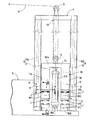
添付図面において、図1〜図5は、本発明の第1実施例を示すものであって、図1は、省力グラブ作業船を示す全体図、図2は、重量変更手段を示す側面図(図1の2部矢視拡大図)、図3は図2の3−3線断面図、図4は図2の4−4線拡大断面図、図5は、重錘の重量変更手段の要部を示す分解斜視図である。また図6〜図9は、本発明の第2実施例を示すものであって、図6は重量変更手段を示す側面図(図2対応図)、図7は図6の7−7線拡大断面図、図8は図6の8−8線拡大断面図、図9は重量変更手段の要部を示す斜視図である。さらに図10〜図12は、本発明の第3実施例を示すものであって、図10は省力グラブ作業船を示す全体図、図11は図10の11部拡大図(図2,図6対応図)、図12は図11の12−12線断面図である。さらに図13は、第4実施例に係る重量変更手段を示す図2対応図であり、図14は、参考例に係る省力グラブ作業船を示す全体図である。
In the accompanying drawings, FIGS. 1 to 5 show a first embodiment of the present invention, FIG. 1 is an overall view showing a labor-saving grab work boat, and FIG. 2 is a side view showing a weight changing means. FIG. 3 is a sectional view taken along line 3-3 in FIG. 2, FIG. 4 is an enlarged sectional view taken along line 4-4 in FIG. 2, and FIG. It is a disassembled perspective view which shows a part. 6 to 9 show a second embodiment of the present invention. FIG. 6 is a side view showing the weight changing means (corresponding to FIG. 2), and FIG. 7 is an enlarged view of line 7-7 in FIG. 8 is an enlarged sectional view taken along line 8-8 in FIG. 6, and FIG. 9 is a perspective view showing the main part of the weight changing means. 10 to 12 show a third embodiment of the present invention, in which FIG. 10 is an overall view showing a labor-saving grab work ship, and FIG. 11 is an enlarged view of
先ず、第1実施例を示す図1〜図5において、省力グラブ作業船の自力航行可能な台船1上には、作業台2が水平面内で旋回可能に搭載されており、この作業台2にはブームBが起伏可能に枢支される。このブームBの起伏駆動は、該ブームBと作業台2間に介装した伸縮シリンダ3により行われ、またブームBの先端には、索条案内用のシーブSが回転自在に支持されている。
First, in FIGS. 1 to 5 showing the first embodiment, a work table 2 is mounted so as to be able to swivel in a horizontal plane on a self-navigable carriage 1 of a labor-saving grab work ship. The boom B is pivotally supported so that it can be raised and lowered. The raising / lowering drive of the boom B is performed by the
このシーブSには、索条Aの中間部が巻き掛けられており、その索条Aの一端側は、シーブSから垂下し、その端末部は、水底の土砂を把持可能なグラブバケットGの基部が結着されていて、該バケットGをブームBの先端で索条Aを介して懸吊できるようになっている。 An intermediate portion of the rope A is wound around the sheave S, one end side of the rope A is suspended from the sheave S, and the terminal portion of the grab bucket G capable of gripping the sediment at the bottom of the water. The base is bound, and the bucket G can be suspended at the tip of the boom B via the rope A.
このグラブバケットGは、基枠Gmに左右一対のバケット爪Ga,Gbを開閉揺動可能に軸支して構成され、また基枠Gmと各バケット爪Ga,Gbb間には、その各バケット爪に対する強制開閉装置(図示せず)がそれぞれ設けられ、該強制開閉装置は、作業台2にある運転室から遠隔操作できるようになっている。尚、グラブバケットGの構造は、従来周知のグラブバケットのそれと同様であるので、これ以上の説明は省略する。 The grab bucket G is configured by pivotally supporting a pair of left and right bucket claws Ga, Gb on a base frame Gm so that the bucket claws Ga, Gb can be opened and closed, and between each bucket pawl Ga, Gbb. A forced opening / closing device (not shown) is provided for each, and the forced opening / closing device can be remotely operated from the cab in the work table 2. Since the structure of the grab bucket G is the same as that of a conventionally known grab bucket, further explanation is omitted.
作業台2の一側には、上下方向に延びる昇降案内枠4が立設され、その昇降案内枠4の上端中央部に固定滑車5が回転自在に軸支される。この昇降案内枠4には、バケット重量軽減用の重錘Wが昇降可能に案内され、その重錘Wの主要部をなす重錘本体Wmの上端中央部には、動滑車6が回転自在に軸支される。
On one side of the work table 2, an
前記重錘本体Wmは、図示例では互いに間隔をおいて平行に並ぶ左右側壁部7a,7bと、その両側壁部7a,7bの上端間を一体に結合する上壁部7cとで門型に形成される。その左右側壁部7a,7bの両外側面と、それらに対応する昇降案内枠4の左右両側枠部との間には、重錘Wの昇降を案内する昇降案内手段8が設けられる。
In the illustrated example, the weight main body Wm is formed in a gate shape with left and right
その昇降案内手段8は、図示例では昇降案内枠4に固設されて上下方向に延びる案内レール4gと、この案内レール4gに上下方向にのみ摺動可能に係合すべく重錘本体Wmに固設された複数のスライダ9とで構成されるが、重錘Wを安定よく昇降案内し得るものであれば、図示例の構造に限定されない。例えば、スライダ9に、案内レール4gを転動し得る回転輪(図示せず)を回転自在に軸支し、この回転輪を介して案内レール4gにスライダ9を昇降案内させるようにしてもよい。
In the illustrated example, the lift guide means 8 is fixed to the
前記索条Aの他端側は、前記シーブS及び固定滑車5を経て前記動滑車6に巻き掛けられていて、重錘Wを昇降案内枠4内で垂下させており、その索条Aの他端側の端末部は、昇降案内枠4の上端部の適所に結着10される。前記動滑車6及び固定滑車5の組は、少なくとも1組あればよいが、図示例のように複数組を並設(伝動経路上は直列配置)した場合には、重錘Wの昇降ストロークが短くてもグラブバケットGの昇降ストロークを十分長く確保することができる。
The other end side of the rope A is wound around the
重錘本体Wmの上端部と、作業台2又は昇降案内枠4との間には、重錘本体Wmの左右側壁部7a,7bの相互間で上下方向に延びていて該重錘Wを強制的に昇降させる昇降シリンダCYが介装され、これが本発明の昇降手段を構成する。この昇降シリンダCYは、例えばグラブバケットGを水面下に降下させる際には油圧により伸長駆動され、またグラブバケットGを上昇させる際には油圧を解放して収縮駆動される。尚、重錘Wの設定重量によっては、グラブバケットGを上昇させる際にも昇降シリンダCYを油圧により収縮駆動可能に構成してもよい。
Between the upper end portion of the weight main body Wm and the work table 2 or the lifting
また昇降シリンダCYは、図示例ではテレスコピック型の多段シリンダで構成されていて、重錘Wの十分な昇降ストロークを確保できるようにしているが、前記動滑車6及び固定滑車5の組を多数組として重錘Wの昇降ストロークを比較的短く設定した場合には、一段の昇降シリンダを使用することも可能である。
In the illustrated example, the elevating cylinder CY is formed of a telescopic multi-stage cylinder so as to ensure a sufficient elevating stroke of the weight W. However, a large number of sets of the
以上の構成は、従来公知の省力グラブ作業船の基本構成と同様であり、本実施例では、更に重錘Wの全体重量を、重錘本体Wmを引き続き使用したまま(即ち索条Aにセットしたままの状態で)、該重錘Wの全体重量を任意に変更可能な重量変更手段Cが台船1に装備される点に特徴がある。 The above configuration is the same as the basic configuration of a conventionally known labor-saving grab work boat. In this embodiment, the entire weight of the weight W is further used while the weight main body Wm is continuously used (that is, set to the rope A). The weight changing means C that can arbitrarily change the entire weight of the weight W is equipped on the carrier 1 in the state where the weight is kept.
この重量変更手段Cは、台船1内(図示例では作業台2上の昇降案内枠4内)に収納された少なくとも1個(図示例では2個)の重量調整用の重錘片W1,W2と、索条Aの他端側に動滑車6を介して垂下される重錘本体Wmに各重錘片W1,W2を着脱可能に結合し得る結合手段Jとを備える。
The weight changing means C includes at least one (two in the illustrated example) weight adjusting weight piece W1, housed in the carriage 1 (in the illustrated example, the elevating
その結合手段Jは、重錘本体Wmの左右側壁部7a,7bの下端に下向きに一体的に延設された複数の連結棒11と、この連結棒11を抜差可能に挿通できるようにして重錘片W1,W2に形成された連結孔12と、その連結孔12を連結棒11に挿通させた状態で各重錘片W1,W2を連結棒11に串刺し状に挿通、締結し得る連結ボルト13と、このボルト13に螺合可能として各重錘片W1,W2に固着されるナット14とで構成される。そして各重錘片W1,W2及び連結棒11には、連結ボルト13を挿通し得るボルト孔15,16がそれぞれ形成される。而して、上記連結ボルト13により、必要個数の重錘片W1,W2を連結棒11(従って重錘本体Wm)に結合すれば、重錘Wの全体重量を任意に且つ段階的に変更可能である。
The coupling means J is configured so that a plurality of connecting
次に第1実施例の作用を説明する。図1の実線の状態より水底の土砂を採取する作業を行うに当たっては、先ず、グラブバケットGを拡開状態に保持し、且つ昇降シリンダCYを伸長駆動して重錘Wを昇降案内枠4内で上昇させることにより、索条Aを繰り出してグラブバケットGを徐々に下降させる。そして、グラブバケットGが水底に到達すると、該バケットGを強制閉成させて水底の土砂を強制的に掬いあげ、該バケットG内に把持させる。
Next, the operation of the first embodiment will be described. In performing the work of collecting sediment from the bottom of the solid line in FIG. 1, first, the grab bucket G is held in an expanded state, and the lifting cylinder CY is extended to drive the weight W in the lifting
しかる後に、昇降シリンダCYの油圧を解放し或いは同シリンダCYを収縮駆動することにより、重錘Wを昇降案内枠4内で下降させ、これと共に索条Aを牽引してグラブバケットGを引き揚げる。この場合に、重錘Wの重量とグラブバケットGの重量とを一部又は全部相殺させることができるため、グラブバケットGの昇降駆動のための動力を節減できると共に、該バケットGをスムーズに昇降させることができる。
Thereafter, the hydraulic pressure of the lifting cylinder CY is released or the cylinder CY is contracted to lower the weight W in the lifting
ところで重錘Wの全体重量は、大きければ大きいほどグラブバケットGの上昇駆動力が少なくて済むが、その反面、グラブバケットGの下降時に必要な駆動力も大きくなってしまい、従って、重錘Wの全体重量は、グラブバケットGの上昇と下降の両方の観点から最も作業能率が良く動力節減が図られる設定値が適宜選定されるべきである。 By the way, the larger the overall weight of the weight W, the smaller the driving force required to lift the grab bucket G. However, on the other hand, the driving force required when the grab bucket G is lowered increases. The total weight should be selected as appropriate from the viewpoint of both raising and lowering of the grab bucket G so that the work efficiency is the highest and the power can be saved.
また一般にグラブバケットGは、これが把持しようとする土砂の硬度の違いや、バケットの一回当たりの土砂把持量の違い等に合わせて仕様の異なる幾つかの種類のバケット(図示せず)が用意されるものであり、それらを浚渫現場の状況に合わせて適宜使い分けることにより、作業能率の向上を図ることができるが、グラブバケットGを仕様の異なる他のバケットに交換した場合には、その交換に伴いバケット重量が大きく変更されてしまうことがある。 In general, the grab bucket G has several types of buckets (not shown) with different specifications according to the difference in the hardness of the earth and sand to be gripped and the difference in the amount of earth and sand held per bucket. It is possible to improve the work efficiency by properly using them according to the situation at the dredging site. However, if the grab bucket G is replaced with another bucket with different specifications, the replacement is necessary. As a result, the bucket weight may be significantly changed.
そこで本実施例では、このようなバケット重量の大きな変更に対応するために、前記した重錘変更手段Cにより(具体的には、重錘本体Wmに適宜個数の重錘片W1,W2を結合し或いは離脱させることにより)、重錘Wの全体重量をバケット重量に合わせて段階的に変更可能としている。この重量変更に当たっては、既存の重錘本体Wmを引き続き使用したまま(即ち索条Aにセットした状態のまま)でよく、別の大型の重錘本体とそっくり交換する必要はないため、それだけ取扱いが簡便となり、コスト節減が図られる。しかも、管理や取扱いの容易な比較的小型の重錘片W1,W2を複数個用意し、これを重錘本体Wmに単に脱着するだけで、重錘Wの全体重量を簡単に変更することができる。 Therefore, in this embodiment, in order to cope with such a large change in the bucket weight, the weight changing means C described above (specifically, an appropriate number of weight pieces W1, W2 are coupled to the weight body Wm). The total weight of the weight W can be changed stepwise according to the bucket weight. When changing the weight, the existing weight body Wm can be used as it is (that is, it remains set on the rope A), and it is not necessary to replace it with another large weight body. Can be simplified and cost can be saved. Moreover, it is possible to easily change the overall weight of the weight W simply by preparing a plurality of relatively small weight pieces W1 and W2 that are easy to manage and handle and detaching them from the weight body Wm. it can.
次に図6〜図9を参照して、本発明の第2実施例を説明する。この実施例は、重錘本体Wmと重錘片W1,W2間の結合手段J′のみが前記実施例と相違しているので、その相違部分だけを説明する。尚、その他の構成要素には、第1実施例中の対応する構成要素と同様の参照符号を付している(以下の第3、第4実施例も同様)。 Next, a second embodiment of the present invention will be described with reference to FIGS. In this embodiment, only the connecting means J 'between the weight body Wm and the weight pieces W1, W2 is different from the above embodiment, so only the difference will be described. The other components are denoted by the same reference numerals as the corresponding components in the first embodiment (the same applies to the following third and fourth embodiments).
この第2実施例の結合手段J′は、重錘本体Wmの左右側壁部7a,7bの下端部および上側の重錘片W1の下端部にそれぞれ設けられたロック爪機構20と、そのロック爪機構20と協働すべく下側の重錘片W1,W2の上面に設けられた係止ボックス21とで構成される。
The coupling means J ′ of the second embodiment includes a
各ロック爪機構20は、重錘本体Wmの左右側壁部7a,7bの下端部および上側の重錘片W1の下端部にそれぞれ固設されたボックス状のロックハウジング20aと、そのロックハウジング20aの下壁にロック位置とロック解除位置との間で回動可能に軸支されて該下壁より下方に突出するロック爪20bと、そのロック爪20bを前記ロック位置とロック解除位置との間で強制回動させるべくロックハウジング20a内に収容された駆動装置20cとで構成され、その駆動装置20cは、図示例では平行リンク機構23と油圧シリンダ24とを組み合わせて構成される。
Each
また各係止ボックス21の上壁には、対応するロック爪20bに係脱可能な長孔状の係止孔21aが形成される。
Further, on the upper wall of each
従って、重錘本体Wmの左右側壁部7a,7bの下端部と下側の重錘片W1との間において、ロック爪20bをロック解除位置に保持した状態で係止ボックス21の係止孔21a内に挿通、下降させ、しかる後に該ロック爪20bをロック位置まで回動させて係止孔21aの開口縁部に係止させれば、その重錘本体Wmと重錘片W1との間が結合される。これと同様に上側の重錘片W1と下側の重錘片W2との間において、ロック爪20bをロック解除位置に保持した状態で係止ボックス21の係止孔21a内に挿通、下降させ、該ロック爪20bをロック位置まで回動させて係止孔21aに係止させれば、その重錘片W1,W2間が結合される。尚、ロック解除は、上記と逆の手順で行えばよい。
Accordingly, the locking
而して、この第2実施例においても、結合手段J′により、必要個数の重錘片W1,W2を重錘本体Wmに順次、直列に結合することにより、重錘Wの全体重量を任意に且つ段階的に変更可能であり、従って、第1実施例と同様の効果が期待できる。 Thus, also in the second embodiment, the total weight of the weight W can be arbitrarily set by connecting the necessary number of weight pieces W1, W2 to the weight body Wm in series by the connecting means J '. Therefore, the same effect as that of the first embodiment can be expected.
次に図10〜図12を参照して、本発明の第3実施例を説明する。この実施例は、重量変更手段Cだけが前記実施例と相違しているので、その相違部分だけを説明する。 Next, a third embodiment of the present invention will be described with reference to FIGS. In this embodiment, since only the weight changing means C is different from the above embodiment, only the difference will be described.
即ち、この第3実施例の重量変更手段Cは、索条Aの他端側に動滑車6を介して垂下される重錘本体Wmに設けられて重量変更用の水34を貯留可能なタンク部としての中空部30と、その中空部30への液体供給手段としての給水手段3Iと、同中空部30からの液体排出手段としての排水手段32とを備える。
In other words, the weight changing means C of the third embodiment is provided in a weight body Wm suspended from the other end side of the rope A via the
門型をなす重錘本体Wmは、それの少なくとも一部が貯水タンクとなるように中空に形成されており、その中空部30の、左右側壁部7a,7b内に位置する空間部分は、その底部相互が、昇降シリンダCYを迂回して水平に延びる連通管33で連通される。
The weight body Wm having a gate shape is formed hollow so that at least a part of the weight main body Wm becomes a water storage tank, and the space portion of the
前記給水手段31は、周辺水域の水を前記中空部30に取り込み可能に構成されるものであって、それは、周辺水域と中空部30a間を連通させる導水管31aと、その導水管31aに互いに直列に設けられる断接可能なジョイント31b及び開閉操作可能な開閉弁31cと、その導水管31aに周辺水域の水を強制的に汲み上げて中空部30に圧送するポンプ31dとを備える。
The water supply means 31 is configured to be able to take in water in the surrounding water area into the
尚、図示はされないが、中空部30の水面レベル(従って調整重量)を確認するための確認手段、例えば水面レベルを目視するための透明なモニター窓、或いは水面レベルを検出するためのレベルセンサ等が、重量本体Wmに付設される。
Although not shown, a confirmation means for confirming the water surface level (and hence the adjustment weight) of the
また前記排水手段32は、前記中空部30内に貯溜した水34を周辺水域に排水可能に構成されるものであって、それは、周辺水域と中空部30a間を連通させる排水管32aと、その排水管32aに互いに直列に設けられる断接可能なジョイント32b及び着脱可能な開閉弁32cとを備えている。尚、上記排水管32aによる排水は、重力を利用した自然落下により行われるようになっているが、必要に応じて強制排水用のポンプを用いてもよい。
The drainage means 32 is configured to be able to drain the
また、前記導水管31aおよび排水管32aの各々は、それらが重錘本体Wmの昇降動作に無理なく追従し得るように少なくとも一部が可撓性を有しており、しかも重錘本体Wmが最上昇しても余裕があるように十分な弛みを付与されている。
Each of the
而して本実施例では、重錘本体Wmの中空部30への液体(水)の供給・排出により、重錘Wの全体重量の変更を容易に、しかも連続的にきめ細かく行うことができる利点がある。しかも、図示例では、前記給水手段31が、周辺水域の水を前記中空部30に強制的に取り込み可能であり、且つ前記排水手段32が、該中空部30の水を周辺水域に排出可能であるので、重量変更用の水34として、現場周辺水域の水をそのまま利用でき、従って、重量変更用の水を台船1内(重錘W外)に特別に貯溜しておく必要がなく、それだけ設備の簡素化やコスト節減を図ることができる。
Thus, in this embodiment, the total weight of the weight W can be easily and continuously changed finely by supplying and discharging the liquid (water) to and from the
尚、前記ポンプ31dは、重量変更のために専用のポンプを使用してもよいが、台船1に搭載される他の用途のポンプ(例えば重機油圧冷却用或いはエンジン冷却用の冷却水ポンプや消火用ポンプ)を兼用することにより、コスト節減を図ることができる。
The
上記第3実施例の変形例としては、例えば、台船1の内部または外部に重錘Wから分離独立した液体供給源、例えば液体貯溜槽(図示せず)を設けておき、この液体供給源(貯溜槽)と重錘本体Wmの中空部30との間で、液体供給手段としての給水手段31、並びに液体排出手段としての排水手段32により液体(水)の供給・排出を行うようにしたものが考えられる。
As a modified example of the third embodiment, for example, a liquid supply source that is separated and independent from the weight W, for example, a liquid storage tank (not shown) is provided inside or outside the carriage 1, and this liquid supply source is provided. The liquid (water) is supplied / discharged between the (storage tank) and the
また図13には、本発明の第4実施例が示される。この実施例では、重錘本体Wmにおける動滑車6の取付位置を、重錘本体Wmの下部に配置した点で前記実施例と相違する。この実施例では、動滑車6を重錘本体Wmの下部に配置しても重錘本体Wmをバランスよく垂下できるように、動滑車6や固定滑車5の設置個数を増やすことが望ましく、例えば図示例では、重錘本体Wmをその前後左右において少なくとも4条の索条Aにより安定よく垂下できるように動滑車6及び固定滑車5の組を4組、重錘本体Wmの前後左右に分散配置している。
FIG. 13 shows a fourth embodiment of the present invention. In this embodiment, the mounting position of the
また図14には、参考例が示される。この参考例では、索条A1,A2がグラブバケットGの昇降操作用と重錘垂下用との二系統に分けて配設され、これに伴い、ブームB上端のシーブも二系統、即ち第1,第2シーブS1,S2に分けて配設されている。 FIG. 14 shows a reference example. In this reference example, the ropes A1 and A2 are divided into two systems for raising and lowering the grab bucket G and for hanging the weight, and accordingly, the sheave at the upper end of the boom B is also divided into two systems, that is, the first system. The second sheaves S1 and S2 are arranged separately.
而して本参考例において、グラブバケットGを昇降操作するための第1索条A1は、それの一端側がグラブバケットGに結着され且つ他端側が第1シーブS1を経て作業台2又は昇降案内枠4上のウインチ40に接続され、このウインチ40の索条巻取り作動により該バケットGが上昇し、索条繰り出し作動により該バケットGが下降する。
Thus, in the present reference example, the first rope A1 for raising and lowering the grab bucket G is connected to the grab bucket G at one end side thereof, and the work table 2 or the elevator side at the other end side through the first sheave S1. The bucket G is connected to the
一方、重錘垂下用の第2索条A2は、グラブバケットGに一端側が結着されると共に他端側が第2シーブS2及び固定滑車5を経て動滑車6に巻き掛けられて重錘Wを垂下させ、従って、重錘Wの全体重量を第2索条A2を介してグラブバケットGの重量と一部又は全部相殺させることができる。
On the other hand, the second rope A2 for hanging the weight is attached to the grab bucket G at one end side, and the other end side is wound around the moving
そして、このようなタイプの省力グラブ作業船においても、前記した各実施例の重錘変更手段Cの何れかが実施可能であり(図14では第1実施例の重錘変更手段Cを実施した場合を図示)、前記各実施例と同様の作用効果が期待できる。 Further, even in this type of labor-saving grab work boat, any of the weight changing means C of the above-described embodiments can be implemented (in FIG. 14, the weight changing means C of the first embodiment is implemented). In this case, the same effects as those in the above embodiments can be expected .
以上、本発明の実施例を詳述したが、本発明はその要旨を逸脱しない範囲で種々の設計変更を行うことが可能である。 As mentioned above, although the Example of this invention was explained in full detail, this invention can perform a various design change in the range which does not deviate from the summary.
例えば、前記実施例では、ブームBを起伏可能に枢支する作業台2を台船1に対し水平面内で(即ち鉛直軸線周りに)旋回可能に搭載したものを示したが、本発明では、作業台を台船に相対移動不能に固着してもよいし、或いはスライド可能に搭載してもよい。 For example, in the above-described embodiment, the work table 2 that pivotally supports the boom B so that it can be raised and lowered is mounted on the carriage 1 so as to be able to turn in a horizontal plane (that is, around the vertical axis). The work table may be fixed to the carriage so as not to move relative thereto, or may be slidably mounted.
また前記実施例では、台船1が自力航行可能であるものを示したが、本発明では、自力航行が不能な台船を使用し、これを他船に牽引させるようにしてもよい。 In the above embodiment, the trolley 1 is capable of navigating by itself. However, in the present invention, a trolley that is not capable of navigating by itself may be used and pulled by another ship .
また第1〜第3実施例では、ブームB先端のシーブS,S1,S2を各1個だけ設けたものを示したが、本発明では、グラブバケットGや重錘Wを安定よく垂下させるために、同一機能のシーブを複数個ずつ、並列使用してもよい。この場合、それらシーブに案内される索条も複数条となり、それら索条が巻き掛けられる固定滑車や動滑車も、シーブの数に合わせて複数組必要となる。 In the first to third embodiments, only one sheave S, S1, S2 at the tip of the boom B is provided. However, in the present invention, the grab bucket G and the weight W are stably suspended. In addition, a plurality of sheaves having the same function may be used in parallel. In this case, there are a plurality of ropes guided by the sheaves, and a plurality of fixed pulleys and moving pulleys around which the ropes are wound are required in accordance with the number of sheaves.
また重錘Wの全体重量の変更のために第1,第2,第4実施例では、重錘片W1,W2を重錘本体Wmに対し脱着する方式を採用し、また第3実施例では、重錘本体Wmのタンク部30内に液体(水、泥水、油等の液体、或いはこれらの混合液体を含む)を供給・排出する方式を採用したものを示したが、本発明では、その両方式を併用して重錘Wの全体重量を変更するようにしてもよい。
Further, in order to change the overall weight of the weight W, the first, second and fourth embodiments adopt a method in which the weight pieces W1, W2 are attached to and detached from the weight body Wm, and in the third embodiment, In the present invention, a method of supplying and discharging liquid (including liquids such as water, muddy water, oil, or a mixed liquid thereof) into the
A・・・索条
A1・・第1索条
A2・・第2索条
B・・・ブーム
C・・・重量変更手段
CY・・昇降手段としての昇降シリンダ
G・・・グラブバケット
S・・・シーブ
S1・・第1シーブ
S2・・第2シーブ
J,J′・・結合手段
W・・・重錘
Wm・・重錘本体
W1,W2・・重錘片
1・・・台船
2・・・作業台
5・・・固定滑車
4・・・昇降案内枠
6・・・動滑車
7a,7b・・重錘本体の左、右側壁部
7c・・・・・重錘本体の上壁部
8・・・昇降案内手段
30・・タンク部としての中空部
31・・液体供給手段としての給水手段
32・・液体排出手段としての排水手段
40・・ウインチ
A ... rope A1 ... first rope A2 ... second rope B ... boom C ... weight change means CY ... lift cylinder G as lift means grab bucket S ... · Sheave S1 · · 1st sheave S2 · · 2nd sheaves J, J '· · · · · · · · · · · · · · · · · · · · · Weight body W1, W2 · · · Weight piece 1 · · ·
7a, 7b ... the left and right side walls of the weight body
7c: Upper wall of the weight body
8. Elevating and guiding means 30 ..
Claims (2)
前記重錘(W)の重錘本体(Wm)は、前記昇降シリンダ(CY)を挟んでその左右に並ぶ左、右側壁部(7a,7b)と、その左、右側壁部(7a,7b)の上端間を一体に結合する上壁部(7c)とを備えていて、その上壁部(7c)に前記昇降シリンダ(CY)の上端部が連結され、
前記重錘(W)の全体重量を任意に変更可能な重量変更手段(C)が、前記昇降シリンダ(CY)の左右両側で前記台船(1)上に上下に重ねて載置し得る少なくとも2個の重錘片(W1,W2)と、それら重錘片(W1,W2)の一部又は全部を前記左、右側壁部(7a,7b)の下端部に上下に重ねた状態で着脱可能に結合し得る結合手段(J,J′)とで構成されることを特徴とする、省力グラブ作業船。 A boom (B) pivotally supported by a workbench (2) mounted on a trolley (1) and supported so that a sheave (S) is rotatably supported at the tip, and a side of the workbench (2). elevating lift guide frame erected Rutotomoni top to a fixed pulley (5) is pivotally supported and (4), and the weight of the movable pulley (6) is pivotally supported (W), the weight (W) Lift guide means (8) for guiding the guide frame (4) so that it can be moved up and down in a fixed posture and cannot rotate and move laterally, a grab bucket (G) capable of gripping the sediment on the bottom of the water, and this grab bucket (G) A rope (A) having one end attached thereto and the other end wound around the movable pulley (6) through the sheave (S) and the fixed pulley (5) to suspend the weight (W); The weight is interposed between the weight (W) and the work table (2) or the lifting guide frame (4) and extends vertically. W) and a lifting cylinder for lifting and lowering (CY), said so as to offset the weight and part or all of the grab buckets (G) through the entire weight of the weight (W) rope (A) A labor-saving grab work boat ,
The weight body (Wm) of the weight (W) has left and right side wall portions (7a, 7b) and left and right side wall portions (7a, 7b) arranged on the left and right sides of the elevating cylinder (CY). ) And an upper wall portion (7c) that integrally couples the upper end portions of the elevating cylinder (CY) to the upper wall portion (7c),
The weight changing means (C) capable of arbitrarily changing the entire weight of the weight (W) can be placed on the carriage (1) so as to be vertically stacked on both left and right sides of the elevating cylinder (CY). Two weight pieces (W1, W2) and a part or all of these weight pieces (W1, W2) are attached and detached in a state where they are vertically stacked on the lower ends of the left and right side wall portions (7a, 7b). A labor-saving grab work boat characterized by comprising coupling means (J, J ′) that can be coupled together .
前記重錘(W)の重錘本体(Wm)は、前記昇降シリンダ(CY)を挟んでその左右に並ぶ左、右側壁部(7a,7b)と、その左、右側壁部(7a,7b)の上端間を一体に結合する上壁部(7c)とを備えていて、その上壁部(7c)に前記昇降シリンダ(CY)の上端部が連結され、
前記重錘(W)の全体重量を任意に変更可能な重量変更手段(C)が、前記左、右側壁部(7a,7b)を各々中空に形成して構成された、重量変更用の液体を貯溜可能なタンク部(30)と、前記タンク部(30)への液体供給手段(31)と、同タンク部(30)からの液体排出手段(32)とで構成されることを特徴とする、省力グラブ作業船。 A boom (B) pivotally supported by a workbench (2) mounted on a trolley (1) and supported so that a sheave (S) is rotatably supported at the tip, and a side of the workbench (2). The elevating guide frame (4), which is erected and on which the fixed pulley (5) is pivotally supported, the weight (W) on which the movable pulley (6) is pivotally supported, and the weight (W) is raised and lowered Lift guide means (8) for guiding the guide frame (4) so that it can be moved up and down in a fixed posture and cannot rotate and move laterally, a grab bucket (G) capable of gripping the sediment on the bottom of the water, and this grab bucket (G) A rope (A) having one end attached thereto and the other end wound around the movable pulley (6) through the sheave (S) and the fixed pulley (5) to suspend the weight (W); The weight is interposed between the weight (W) and the work table (2) or the lifting guide frame (4) and extends vertically. An elevating cylinder (CY) for elevating and lowering W), and the entire weight of the weight (W) is partially or completely offset with the weight of the grab bucket (G) via the rope (A). A labor-saving grab work boat,
The weight body (Wm) of the weight (W) has left and right side wall portions (7a, 7b) and left and right side wall portions (7a, 7b) arranged on the left and right sides of the elevating cylinder (CY). ) And an upper wall portion (7c) that integrally couples the upper end portions of the elevating cylinder (CY) to the upper wall portion (7c),
A weight changing liquid in which the weight changing means (C) capable of arbitrarily changing the entire weight of the weight (W) is formed by forming the left and right side walls (7a, 7b) hollow, respectively. the reservoir can be a tank portion (30), a liquid supply means (31) of the tank section (30), and wherein the constructed out with the liquid discharge means (32) from the tank (30) to, labor-saving grab work boats.
Priority Applications (1)
| Application Number | Priority Date | Filing Date | Title |
|---|---|---|---|
| JP2007116193A JP4939295B2 (en) | 2007-04-25 | 2007-04-25 | Labor-saving grab work boat |
Applications Claiming Priority (1)
| Application Number | Priority Date | Filing Date | Title |
|---|---|---|---|
| JP2007116193A JP4939295B2 (en) | 2007-04-25 | 2007-04-25 | Labor-saving grab work boat |
Publications (2)
| Publication Number | Publication Date |
|---|---|
| JP2008274569A JP2008274569A (en) | 2008-11-13 |
| JP4939295B2 true JP4939295B2 (en) | 2012-05-23 |
Family
ID=40052860
Family Applications (1)
| Application Number | Title | Priority Date | Filing Date |
|---|---|---|---|
| JP2007116193A Active JP4939295B2 (en) | 2007-04-25 | 2007-04-25 | Labor-saving grab work boat |
Country Status (1)
| Country | Link |
|---|---|
| JP (1) | JP4939295B2 (en) |
Families Citing this family (2)
| Publication number | Priority date | Publication date | Assignee | Title |
|---|---|---|---|---|
| JP5340749B2 (en) * | 2009-01-06 | 2013-11-13 | 東亜建設工業株式会社 | 浚 渫 Method |
| CN113939629B (en) * | 2019-06-12 | 2023-06-27 | 株式会社小岛组 | Dredging operation ship |
Family Cites Families (6)
| Publication number | Priority date | Publication date | Assignee | Title |
|---|---|---|---|---|
| JPS6053141B2 (en) * | 1981-07-07 | 1985-11-22 | 株式会社小島組 | Labor-saving grab work boat |
| JPS6018165U (en) * | 1983-07-12 | 1985-02-07 | 株式会社 小島組 | Labor-saving grab work boat |
| JPH01280132A (en) * | 1988-05-02 | 1989-11-10 | Kawasaki Heavy Ind Ltd | Bucket dredging device |
| JPH10250959A (en) * | 1997-03-07 | 1998-09-22 | Toshiba Elevator Eng Kk | Counterweight for rope type elevator |
| JP2000318976A (en) * | 1999-05-06 | 2000-11-21 | Nippon Steel Logistics Co Ltd | On-board gate crane |
| JP2007016430A (en) * | 2005-07-06 | 2007-01-25 | Sanyuutekku Kk | Safety device for fire shutter |
-
2007
- 2007-04-25 JP JP2007116193A patent/JP4939295B2/en active Active
Also Published As
| Publication number | Publication date |
|---|---|
| JP2008274569A (en) | 2008-11-13 |
Similar Documents
| Publication | Publication Date | Title |
|---|---|---|
| CN103847930B (en) | offshore drilling vessel | |
| JP4215807B2 (en) | Multi-position wire rope guide | |
| JP4871599B2 (en) | Crane and crane disassembly method | |
| CN107000822B (en) | Offshore drilling ship | |
| WO2013141892A1 (en) | Kingpost crane apparatus & method | |
| CN101913416B (en) | Inland river salvage container | |
| US7216717B2 (en) | Dual elevator system and method | |
| BRPI0916096B1 (en) | VESSEL FOR OPERATION IN SUBMARINE WELLS AND WORKING METHOD OF DITA VESSEL. | |
| BRPI1001533A2 (en) | MAIN FOLDING BOOM ANCHOR AND TRANSPORTABLE GORNID ANCHOR COVERS | |
| JP2020514205A5 (en) | ||
| US20100072158A1 (en) | Drum Frame System For Cranes | |
| CN1243083A (en) | Apparatus for placing sth. in deep water | |
| NO333735B1 (en) | An offshore vessel or platform for carrying out undersea operations. | |
| JP4939295B2 (en) | Labor-saving grab work boat | |
| KR101336396B1 (en) | Crane with micro motion adjustment | |
| CN2920956Y (en) | Multifunction loading and unloading forklift | |
| DK2610160T3 (en) | Propeller lifting system to maintain propellers on floating vessels | |
| NO325335B1 (en) | Device and method of a traverse crane on a floating vessel | |
| NO328785B1 (en) | Device, method and application for moving equipment for cable running in a well | |
| JP4946475B2 (en) | Crane capable of mounting a hydraulic unit, and hydraulic working method and apparatus using the same | |
| US6434866B1 (en) | Device for attaching and detaching a counterweight of construction machine | |
| CN104724623A (en) | Marine movable sundry lifting appliance | |
| JP5324970B2 (en) | Hydraulic hose connection structure of work vehicle with swivel | |
| CN208412052U (en) | A kind of flexible floater rifle battle array draw off gear | |
| JP6105499B2 (en) | Construction machinery |
Legal Events
| Date | Code | Title | Description |
|---|---|---|---|
| A621 | Written request for application examination |
Free format text: JAPANESE INTERMEDIATE CODE: A621 Effective date: 20100422 |
|
| A977 | Report on retrieval |
Free format text: JAPANESE INTERMEDIATE CODE: A971007 Effective date: 20110408 |
|
| A131 | Notification of reasons for refusal |
Free format text: JAPANESE INTERMEDIATE CODE: A131 Effective date: 20110511 |
|
| A521 | Request for written amendment filed |
Free format text: JAPANESE INTERMEDIATE CODE: A523 Effective date: 20110706 |
|
| TRDD | Decision of grant or rejection written | ||
| A01 | Written decision to grant a patent or to grant a registration (utility model) |
Free format text: JAPANESE INTERMEDIATE CODE: A01 Effective date: 20120201 |
|
| A01 | Written decision to grant a patent or to grant a registration (utility model) |
Free format text: JAPANESE INTERMEDIATE CODE: A01 |
|
| A61 | First payment of annual fees (during grant procedure) |
Free format text: JAPANESE INTERMEDIATE CODE: A61 Effective date: 20120224 |
|
| FPAY | Renewal fee payment (event date is renewal date of database) |
Free format text: PAYMENT UNTIL: 20150302 Year of fee payment: 3 |
|
| R150 | Certificate of patent or registration of utility model |
Free format text: JAPANESE INTERMEDIATE CODE: R150 Ref document number: 4939295 Country of ref document: JP Free format text: JAPANESE INTERMEDIATE CODE: R150 |
|
| R250 | Receipt of annual fees |
Free format text: JAPANESE INTERMEDIATE CODE: R250 |
|
| R250 | Receipt of annual fees |
Free format text: JAPANESE INTERMEDIATE CODE: R250 |
|
| R250 | Receipt of annual fees |
Free format text: JAPANESE INTERMEDIATE CODE: R250 |
|
| R250 | Receipt of annual fees |
Free format text: JAPANESE INTERMEDIATE CODE: R250 |
|
| R250 | Receipt of annual fees |
Free format text: JAPANESE INTERMEDIATE CODE: R250 |
|
| R250 | Receipt of annual fees |
Free format text: JAPANESE INTERMEDIATE CODE: R250 |
|
| R250 | Receipt of annual fees |
Free format text: JAPANESE INTERMEDIATE CODE: R250 |
|
| R250 | Receipt of annual fees |
Free format text: JAPANESE INTERMEDIATE CODE: R250 |
|
| R250 | Receipt of annual fees |
Free format text: JAPANESE INTERMEDIATE CODE: R250 |
|
| R250 | Receipt of annual fees |
Free format text: JAPANESE INTERMEDIATE CODE: R250 |