JP4937123B2 - Gas plug connector - Google Patents
Gas plug connector Download PDFInfo
- Publication number
- JP4937123B2 JP4937123B2 JP2007526271A JP2007526271A JP4937123B2 JP 4937123 B2 JP4937123 B2 JP 4937123B2 JP 2007526271 A JP2007526271 A JP 2007526271A JP 2007526271 A JP2007526271 A JP 2007526271A JP 4937123 B2 JP4937123 B2 JP 4937123B2
- Authority
- JP
- Japan
- Prior art keywords
- gas plug
- plug connector
- outlet socket
- gas
- valve
- Prior art date
- Legal status (The legal status is an assumption and is not a legal conclusion. Google has not performed a legal analysis and makes no representation as to the accuracy of the status listed.)
- Expired - Fee Related
Links
Images


Classifications
-
- F—MECHANICAL ENGINEERING; LIGHTING; HEATING; WEAPONS; BLASTING
- F16—ENGINEERING ELEMENTS AND UNITS; GENERAL MEASURES FOR PRODUCING AND MAINTAINING EFFECTIVE FUNCTIONING OF MACHINES OR INSTALLATIONS; THERMAL INSULATION IN GENERAL
- F16L—PIPES; JOINTS OR FITTINGS FOR PIPES; SUPPORTS FOR PIPES, CABLES OR PROTECTIVE TUBING; MEANS FOR THERMAL INSULATION IN GENERAL
- F16L37/00—Couplings of the quick-acting type
- F16L37/60—Couplings of the quick-acting type with plug and fixed wall housing
-
- F—MECHANICAL ENGINEERING; LIGHTING; HEATING; WEAPONS; BLASTING
- F16—ENGINEERING ELEMENTS AND UNITS; GENERAL MEASURES FOR PRODUCING AND MAINTAINING EFFECTIVE FUNCTIONING OF MACHINES OR INSTALLATIONS; THERMAL INSULATION IN GENERAL
- F16L—PIPES; JOINTS OR FITTINGS FOR PIPES; SUPPORTS FOR PIPES, CABLES OR PROTECTIVE TUBING; MEANS FOR THERMAL INSULATION IN GENERAL
- F16L37/00—Couplings of the quick-acting type
- F16L37/28—Couplings of the quick-acting type with fluid cut-off means
- F16L37/38—Couplings of the quick-acting type with fluid cut-off means with fluid cut-off means in only one of the two pipe-end fittings
- F16L37/47—Couplings of the quick-acting type with fluid cut-off means with fluid cut-off means in only one of the two pipe-end fittings with a tap or cock
-
- Y—GENERAL TAGGING OF NEW TECHNOLOGICAL DEVELOPMENTS; GENERAL TAGGING OF CROSS-SECTIONAL TECHNOLOGIES SPANNING OVER SEVERAL SECTIONS OF THE IPC; TECHNICAL SUBJECTS COVERED BY FORMER USPC CROSS-REFERENCE ART COLLECTIONS [XRACs] AND DIGESTS
- Y10—TECHNICAL SUBJECTS COVERED BY FORMER USPC
- Y10T—TECHNICAL SUBJECTS COVERED BY FORMER US CLASSIFICATION
- Y10T137/00—Fluid handling
- Y10T137/598—With repair, tapping, assembly, or disassembly means
- Y10T137/6184—Removable valve with normally disabled supplemental check valve
- Y10T137/6188—Check valve disabled by normally movable main valve part
- Y10T137/6191—Ball check
-
- Y—GENERAL TAGGING OF NEW TECHNOLOGICAL DEVELOPMENTS; GENERAL TAGGING OF CROSS-SECTIONAL TECHNOLOGIES SPANNING OVER SEVERAL SECTIONS OF THE IPC; TECHNICAL SUBJECTS COVERED BY FORMER USPC CROSS-REFERENCE ART COLLECTIONS [XRACs] AND DIGESTS
- Y10—TECHNICAL SUBJECTS COVERED BY FORMER USPC
- Y10T—TECHNICAL SUBJECTS COVERED BY FORMER US CLASSIFICATION
- Y10T137/00—Fluid handling
- Y10T137/598—With repair, tapping, assembly, or disassembly means
- Y10T137/6184—Removable valve with normally disabled supplemental check valve
- Y10T137/6188—Check valve disabled by normally movable main valve part
- Y10T137/6195—Spring bias
-
- Y—GENERAL TAGGING OF NEW TECHNOLOGICAL DEVELOPMENTS; GENERAL TAGGING OF CROSS-SECTIONAL TECHNOLOGIES SPANNING OVER SEVERAL SECTIONS OF THE IPC; TECHNICAL SUBJECTS COVERED BY FORMER USPC CROSS-REFERENCE ART COLLECTIONS [XRACs] AND DIGESTS
- Y10—TECHNICAL SUBJECTS COVERED BY FORMER USPC
- Y10T—TECHNICAL SUBJECTS COVERED BY FORMER US CLASSIFICATION
- Y10T137/00—Fluid handling
- Y10T137/8593—Systems
- Y10T137/87917—Flow path with serial valves and/or closures
- Y10T137/87925—Separable flow path section, valve or closure in each
- Y10T137/87973—Coupling interlocked with valve, or closure or actuator
-
- Y—GENERAL TAGGING OF NEW TECHNOLOGICAL DEVELOPMENTS; GENERAL TAGGING OF CROSS-SECTIONAL TECHNOLOGIES SPANNING OVER SEVERAL SECTIONS OF THE IPC; TECHNICAL SUBJECTS COVERED BY FORMER USPC CROSS-REFERENCE ART COLLECTIONS [XRACs] AND DIGESTS
- Y10—TECHNICAL SUBJECTS COVERED BY FORMER USPC
- Y10T—TECHNICAL SUBJECTS COVERED BY FORMER US CLASSIFICATION
- Y10T137/00—Fluid handling
- Y10T137/8593—Systems
- Y10T137/87917—Flow path with serial valves and/or closures
- Y10T137/88046—Biased valve with external operator
Landscapes
- Engineering & Computer Science (AREA)
- General Engineering & Computer Science (AREA)
- Mechanical Engineering (AREA)
- Quick-Acting Or Multi-Walled Pipe Joints (AREA)
- Valve Housings (AREA)
- Temperature-Responsive Valves (AREA)
- Preventing Unauthorised Actuation Of Valves (AREA)
Description
本発明は、入口側で固定ガスパイプと確実な連結を設定し且つ出口側でガスプラグ特にガスチューブプラグに接続をもたらすガスプラグコネクタに関し、外部との気密性が確立した後にガスプラグが接続されると、ガスの内部流れだけを解放する遮断装置をハウジング内に有するガスプラグコネクタに関する。 The present invention relates to a gas plug connector which establishes a secure connection with a fixed gas pipe on the inlet side and provides a connection to a gas plug, in particular a gas tube plug, on the outlet side, which is connected after the gas tightness with the outside is established. And a gas plug connector having a shut-off device in the housing for releasing only the internal flow of gas.
ガスプラグコネクタは、固定ガスパイプと、家庭用調理器、衣類乾燥機またはグリルのようなガス操作器具とを接続する手段を提供する。これらは、ガス操作器具をガスパイプに接続する単純な手段を提供する。 The gas plug connector provides a means of connecting a stationary gas pipe and a gas handling device such as a home cooker, clothes dryer or grill. These provide a simple means of connecting the gas handling device to the gas pipe.
前記のタイプのガスプラグコネクタは、独国特許第10061653号に開示されている。このガスプラグコネクタは、固定ガスパイプとの確実な接続を行うための一体の入り口ソケットを有するベースと、該ベースにネジ止めされた出口ソケットと、ガスプラグを受け入れるために所定の距離で出口ソケットの外周面を取り囲み且つ他方ではベースにネジ止めされるベースプレートとからなる。さらに、ベースプレートは、壁面取り付けが必要とされる壁にユニットを固着するために用いることができる。フードはベースに取り付け、該フードは、ガスプラグが切り離されるときに出口ソケットの接続開口をカバーで密閉する。 A gas plug connector of the aforementioned type is disclosed in DE 100616653. The gas plug connector includes a base having an integral inlet socket for secure connection with a fixed gas pipe, an outlet socket screwed to the base, and an outlet socket at a predetermined distance to receive the gas plug. It consists of a base plate that surrounds the outer peripheral surface and is screwed to the base on the other side. Further, the base plate can be used to secure the unit to a wall that requires wall mounting. A hood is attached to the base, and the hood seals the connection opening of the outlet socket with a cover when the gas plug is disconnected.
特にアウトドアでガスプラグコネクタを使用するときにより高い安全性のために、ガスパイプは手動で閉じることができることが望ましい。さらに、ガスプラグが手動で開かれるならば、ガスプラグを切り離しまたは接続することを防止することができるべきである。これは、前述したタイプのガスプラグコネクタでは可能でない。 It is desirable that the gas pipe can be manually closed for greater safety, especially when using the gas plug connector outdoors. Furthermore, if the gas plug is manually opened, it should be possible to prevent the gas plug from being disconnected or connected. This is not possible with a gas plug connector of the type described above.
従来、前記の要件に適合させる普通の方法は、このような目的のために公知のボールパイプをガスパイプに取り付けることにより、ガスプラグのためにソケット接続を用いる側ボールバルブの出口では通常のネジ部に変形されている。 Conventionally, the usual way to meet the above requirements is to attach a known ball pipe to the gas pipe for such purposes, so that the normal thread at the outlet of the side ball valve using a socket connection for the gas plug. It has been transformed into.
このソケット接続は、ガス出口の周囲の放射状の案内開口部において、ガス出口で軸方向に移動可能な保持スリーブを用いて放射方向に位置を変えることができるように移動可能な保持ボールを有する。保持ボールの位置は、ガスプラグが接続されるかまたは切り離しされるかのいずれかで決定する。さらに、ボールバルブの操作ハンドルのデザインのために、保持スリーブは、ボールバルブが開かれると保持ボールが閉鎖位置になるような位置に取り付けられる。 This socket connection has a holding ball which is movable in a radial guide opening around the gas outlet so that it can be repositioned radially using a holding sleeve which is axially movable at the gas outlet. The position of the holding ball is determined by whether the gas plug is connected or disconnected. Further, due to the design of the ball valve operating handle, the holding sleeve is mounted in a position such that the holding ball is in the closed position when the ball valve is opened.
さらに、遮断バルブは、ガスプラグが接続されると該ガスプラグによって開かれるボールバルブの内部に収納される。 Further, the shutoff valve is accommodated in a ball valve that is opened by the gas plug when the gas plug is connected.
このタイプの欠点は、ガス出口の開口がカバーされず且つ異物の貫通に対する保護がなされていないことである。さらに、このタイプは、壁面でのフラッシュ据え付けに適しておらず、且つその外観は、見ることができるリビング領域または他の領域で使用するのが望ましいようにはなっていない。
本発明の目的は、付加の遮断バルブを手動で閉じたときだけ接続および切り離しが可能であることによって、ガスプラグを迅速に接続および切り離しできる記述したタイプのガスプラグコネクタを案出することである。さらに、ガスプラグコネクタは、ガスプラグを接続しないときに異物の貫通に対する保護を行うべきである。加えて、ガスプラグコネクタは、フラッシュ据え付けに適合させ且つ見ることができるリビング領域または他の領域で使用するのに適した外観であるべきである。これらの要件は、本発明によって下記のように満たされている。ガスプラグコネクタのハウジングは、一方では案内デバイスと適合するスイッチエレメント用の軸受を有し、該案内デバイスによってハウジングのベースに据え付けたプランジャの一端部が支持される一方、該プランジャの他端部は、ベースのガス導通チェンバ内に配置された遮断バルブのバルブヘッドに連結され、該遮断バルブがスイッチエレメントを経てその開放および閉鎖位置に移動できるようになる。他方では、スイッチエレメントはロッキング装置に接続され、該ロッキング装置によって、遮断バルブがその開放位置にあるならばガスプラグの接続が防止される一方、遮断バルブがその閉鎖位置にあるならば接続を可能とする。 It is an object of the present invention to devise a gas plug connector of the type described which can quickly connect and disconnect gas plugs by allowing connection and disconnection only when the additional shutoff valve is manually closed. . Furthermore, the gas plug connector should provide protection against foreign material penetration when the gas plug is not connected. In addition, the gas plug connector should be of an appearance suitable for use in a living area or other area that is adapted and viewable for flash installation. These requirements are met by the present invention as follows. The housing of the gas plug connector, on the one hand, has a bearing for the switch element that is compatible with the guide device, and the guide device supports one end of a plunger mounted on the base of the housing, while the other end of the plunger is , Connected to the valve head of a shut-off valve arranged in the gas conduction chamber of the base, so that the shut-off valve can be moved to its open and closed positions via the switch element. On the other hand, the switch element is connected to a locking device which prevents the gas plug from being connected if the shut-off valve is in its open position, while allowing connection if the shut-off valve is in its closed position. And
これによって、前述した現状の技術における欠点を取り除く方法を提供している。スイッチエレメントの手動操作は、遮断バルブを介してガスパイプを開放または閉鎖するとともに、結果として同時にガス供給を遮断または開放することになる。カバーは、ガスプラグを接続しないときに接続開口を密閉し、それによって異物の貫通を防止している。 This provides a method for eliminating the drawbacks of the current technology described above. Manual operation of the switch element opens or closes the gas pipe via the shut-off valve and at the same time shuts off or opens the gas supply. The cover seals the connection opening when the gas plug is not connected, thereby preventing the penetration of foreign matter.
本発明の付加的で有益な設計は、他の請求項に提示されている。例えば、スイッチエレメントをベースプレートに据え付けるならば特に有益である。 Additional and beneficial designs of the invention are presented in the other claims. For example, it is particularly beneficial if the switch element is installed on a base plate.
可能な限り組み立ておよび製造を単純化するために、プランジャが、バネエレメントによって相互に連結される両部分を有するその前後方向の2部分であるならば有益である。 In order to simplify the assembly and manufacture as much as possible, it is beneficial if the plunger is its two parts in its longitudinal direction with both parts interconnected by a spring element.
さらに、特に有益な実例では、ガス流れ方向に閉じる遮断バルブがプランジャ上で軸方向に移動可能のバルブヘッドを有し、該プランジャは、開口の方向に作用するバネの弾力下に、該プランジャ上に設置したハードストップで留まる。適切に設計されたバネによって、流量値が特定の容量を超えたならば、例えば、ガスパイプにおいて漏れ下流で起こりうるのと同様に、本来は手動操作される遮断バルブを自動的に開かせることがこの配置によって可能であり、それによって安全性をよりいっそう高めることになる。 Furthermore, in a particularly useful example, a shut-off valve that closes in the direction of gas flow has a valve head that is axially displaceable on the plunger, the plunger being on the plunger under the elasticity of a spring acting in the direction of the opening. Stay at the hard stop installed at. Appropriately designed springs can automatically open an originally manually operated shut-off valve if the flow value exceeds a certain capacity, for example, as can happen downstream of a leak in a gas pipe. This arrangement is possible and thereby further increases safety.
ガスパイプが手動で開かれたとき、スイッチエレメントに接続したロッキング装置によってガスプラグを切り離しまたは接続されることを防止するための簡単な解決策は、ロッキング装置を出口ソケットの軸線に対して垂直方向に移動可能である掛止めスライドとして形成するか、またはロッキング装置を回転中心がプランジャの軸線と出口ソケットの軸線との間にあるロッカースイッチとして形成することである。 A simple solution to prevent the gas plug from being disconnected or connected by a locking device connected to the switch element when the gas pipe is opened manually is to place the locking device in a direction perpendicular to the axis of the outlet socket. Either as a latch slide that is movable, or as a rocker switch with the center of rotation between the axis of the plunger and the axis of the outlet socket.
ここでは締付けリングを使用するならば有益であり、該締付けリングは、出口ソケット上で軸方向に移動可能であり且つ2本の対称配置のリムを有するロッキング装置によってバネの弾力下に支持され、それによって出口ソケットの周辺で放射状の案内開口部内に配置される保持ボールが、締付けリングの内部案内デバイスを経て、該締付けリングの軸方向移動によって公知のように放射方向に移動可能であり、それによってロッキング装置の縦移動が結果として締付けリングの軸方向移動になるように、リムがフォーク状の態様で締付けリングを取り囲んでいる。 It is advantageous here to use a clamping ring, which is axially movable on the outlet socket and supported under the spring's elasticity by a locking device having two symmetrically arranged rims, A holding ball which is arranged in the radial guide opening around the outlet socket thereby can be moved in a radial direction as known by the axial movement of the clamping ring via the clamping ring's internal guiding device, The rim surrounds the clamping ring in a fork-like manner so that the longitudinal movement of the locking device results in an axial movement of the clamping ring.
ロッキング装置として、掛止めスライドを用いるとさらに有利な解決策を提供するものであり、それによって、ワイヤ状部は、掛止めスライドの軸方向に曲げ且つ掛止めスライドのテーパーガイド円錐部内へ突出する2本の対称配置のリムによって、出口ソケットの環状溝に嵌め込まれている。幾つかのリング状のラッチローラは、ワイヤ状部のラインに配置され、該ラッチローラは、ガイド円錐部によって定められた両リム間の距離および溝内に設置された該ワイヤ状部の部分の結果直径に依存して、該溝の基部に設けた放射状の案内開口部から出口ソケットの内部に突出する。 The use of a latch slide as a locking device provides a further advantageous solution, whereby the wire-like part is bent in the axial direction of the latch slide and protrudes into the tapered guide cone of the latch slide. Two symmetrically arranged rims are fitted into the annular groove of the outlet socket. Several ring-shaped latch rollers are arranged in the line of the wire-like part, the latch roller being the distance between the rims defined by the guide cone and the part of the wire-like part installed in the groove. Depending on the resulting diameter, it protrudes from the radial guide opening at the base of the groove into the outlet socket.
次に、本発明に係るガスプラグコネクタは、以下の実施例によってより詳細に説明されるものである。 Next, the gas plug connector according to the present invention will be described in more detail by the following examples.
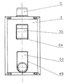
本発明に係るガスプラグコネクタは、図1に示すようにフラッシュ取り付けに適した例において、堅く連結されたベース2、フード3およびベースプレートからなるマルチポートハウジング1を有する。
The gas plug connector according to the present invention has a
ガスプラグコネクタを固定ガスパイプ(図示しない)に堅く相互連結させるための雄ネジ部を有する入口ソケット5と、寸法を合わせるガスプラグ57を受け入れるのに役立つ出口ソケット6とは、ベース2にネジ止めされている。ここで入口ソケット5は、公知の熱遮断装置の形状であればよく、それ故にここではより詳細には説明しない。
An
出口ソケット6の軸線と平行に、ベース2は、ガス導通チェンバ7内へ入る別の開口を有し、該チェンバを閉じる遮断バルブ8を操作することができる。このために、遮断バルブ8のリング状弁座は、この場合に鋸歯状の刻み目を刻設している。以下でより詳細に説明される遮断バルブ8であって、この実施例で用いる遮断バルブ8は、同時に安全遮断装置として設計され、該遮断装置は、流量が所定の容量を超えるとガス導通チェンバ7を閉じる。
Parallel to the axis of the
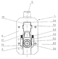
図4に断面で示した開放位置における遮断バルブ8の弁座9は、外側に放射状のリッジ44を有し、該リッジは、周辺に平らに分配され、且つバネエレメント13によって確実に相互連結された2部分を有する2分割プランジャ11,12の第1部分11のために中心配置の軸受10を形成する。バルブヘッド15は、流れ方向に閉じ且つ前後方向に移動可能であって、且つフランジ16とバルブヘッド15との間で弾性密閉エレメントとして役立つO−リング17を有し、該バルブヘッドは、その入口端にフランジ16を有するプランジャ11に取り付け、該フランジの位置は、以下でより詳細に説明される閉鎖流量を調整または設定するために、好ましくは変更することができる。リッジ44で支持されたバネ18の作用のもとに、開放位置におけるバルブヘッド15は、O−リング17で支持されるのに対して、閉鎖位置におけるバルブヘッド15は、弁座9内に配置され且つO−リング55として形成した弾性密閉エレメントによって支持される。
The
開口65を閉じるブッシュ19において、プランジャ11,12の部分12が軸受で前後方向に移動可能であり、且つ気密状態で外方へ導かれる。プランジャ11,12は、ブッシュ19で支持されるバネ20によって遮断バルブ8の閉鎖方向に付勢される。
In the
また、ハウジング1の一部を形成するベースプレート4は、ユニットを壁に、特に住宅ビルディングにおいて、しばしば用いられる種類の概略で示したカーテンウォール45に固着するのに使用することができ、該ベースプレートは、例えば、ネジとダボによりあるいは直接ないし用語として独自のフラッシュソケットを介して公知の手段で固着される。カーテンウォール45中へ突入する筒状のフランジ21は、以下でより詳細に説明される所定の距離でベース2から突出する出口ソケット6の外周面を取り囲む。ベースプレート4は、例えば、図示されないネジ部材によってベース2に連結される。
The
ベース2内へ突入する出口ソケット6の端部は、遮断装置23用の弁座22を形成し、該装置の閉鎖本体24は、出口ソケット6の軸線ならびに弁座22に対して前後方向に移動可能になるように、案内アタッチメント25でベース2に据え付けられる。ここで閉鎖
本体24は、閉鎖の方向において、一端でベース2の内壁に且つ他端で閉鎖本体24で支持される閉鎖バネ26の弾力下にある。閉鎖本体24上に配置し且つ閉鎖位置で弁座22によって支えられるO−リング27は、気密を保証するのに役立つ。閉鎖本体24は、軸方向延長部56によって出口ソケット6内へ突入する。
The end of the
ベース2から離れた先端の領域において、出口ソケット6は、その周囲に分配されるが一平面内で放射状に並んだいくつかの案内開口部28を有する。これらの案内開口部28のそれぞれに、保持ボール29が接続開口30へ部分的に突出するように配置されることにより、案内開口部28の直径が接続開口30の方向へ減少することで保持ボール29が脱落することを防止する。
In the region of the tip remote from the
出口ソケット6上には、軸方向に移動可能な締付けリング31があり、該リングはフランジ21内で確実に案内されるので放射方向に変形することが防がれている。図3から明らかなように、八角形の輪郭は、一方では可能な限り簡単に締付けリング31を製造するため、他方ではベース2で支持された保持バネ32の作用下に軸方向において締付けリング31と可能な限り狭い間隔にするために選択される。締付けリング31内に設置された内部案内デバイス33によって、保持ボール29は、出口ソケット6上での締付けリング31の位置によって、接続開口30が完全に開放されるように案内開口部中で保持されるか、または部分的に接続開口30へ突出するまで案内開口部28の中へ押し込まれる。
On the
カーテンウォール45に固着したベースプレート4は、少なくとも部分的に周辺を取り巻く頸状部46を有し、該頸状部において、特にフード内に配置した留め金48が、フードがベースプレート4を覆うように取り付けられるとぴったり固定する。
The
ガスプラグコネクタの正面での図2に示したフード3は、その正面において、長方形孔49の一部の背後に配置した出口ソケット6の接続開口30を含む長方形の孔49と、以下でより詳細に説明するスイッチエレメント35用の開口64とを有する。縦方向に移動可能なカバー51は、フード3とベースプレート4との間に設置される。
The
図2からフード2およびカバー51を除いたガスプラグコネクタを示す図3から明らかなように、接続開口30の両側にベースプレート4内で支持されるバネ用の案内路52がある。このバネの他端での作用により、ガスプラグが接続されないとき、出口ソケット6の開口部30を露出させる長方形孔49の領域まで、カバー(図3には図示しない)を閉じることになる。
As is apparent from FIG. 3 showing the gas plug connector excluding the
さらに、前述したスイッチエレメント35は、ベースプレート4の凹み34から突出し、プランジャ11,12の縦軸線の平面にあるスイッチエレメント35の旋回軸によって、ベースプレート4内に設置した対応軸受36の回りで旋回する。ベース2に向いた側面には、スイッチエレメント35は、プランジャ12の先端が支持される案内デバイス37を有する。案内デバイス37は、遮断バルブ8が開放または閉鎖位置にあると固定される2個の閉込め位置38,39を有する。可能な限り簡単に製造するために、バネエレメント13は、プランジャ11,12の2部分間での公差補正部材としても役立つ。
Further, the
出口ソケット6に向いた側面には、スイッチエレメント35は、ロッキング装置として役立つ掛止めスライド41を支持するほぞ状突起の取付部40を有する。スイッチエレメント35から離隔した下端で、掛止めスライド41は、締付けリング31をフォーク状に取り囲む2個の対称配置のリム42を有し、それによって掛止めスライド41の縦移動が結果として締付けリング31の軸方向移動になるように、締付けリング31に設置した案内デバイス43上へ突き出している。この一連の操作は、図5の詳細図から明らかなように、案内突出部54を有する掛止めスライド41の2本のリム42それぞれを設置する簡単方法で達成され、該案内突出部に対して、傾斜状の案内デバイス43は、保持バネ32の作用下で軸方向に付勢されている。
On the side facing the
実施例に記載したガスプラグコネクタの機能モードは次の通りである。 The function modes of the gas plug connector described in the embodiment are as follows.
図1において、ガスプラグコネクタは、カバー51で覆われた接続開口30を有する出口ソケット6によって閉鎖位置にある。ガスプラグ57が挿入されていないので、遮断装置23も閉鎖されている。また、スイッチエレメント35が閉鎖位置にあるので、プランジャ12は閉込め位置39に留まり、且つガス導通チェンバ7が閉じられるように、バルブヘッド15は弁座9に設置したO−リング55に押し付けられ、同時にO−リング55とフランジ16との間でO−リング17に押し付けられる。スイッチエレメント35によって、締付けリング31は、取付部40および掛止めスライド41を介して、内部案内デバイス33に留まる保持ボール29が接続開口30を開放するような位置へ到達している。
In FIG. 1, the gas plug connector is in a closed position by an
この位置において、接続開口30が開かれるまでカバー51がバネ53の弾力に逆らって移動された後に、ガスプラグ57を挿入することができ、そして遮断装置23を延長部56を介して開くことが可能である。スイッチエレメント35の一連の作動の後に、案内デバイス37に接するプランジャ12は閉込め位置38まで動かされる。プランジャ11に着座したO−リング17がバルブヘッド15を開き、且つバネ18がバルブヘッド15を開放位置へ移動しうるように、バルブヘッド15とプランジャ11との間に発生する漏れ流れを経て圧力補正が行われる。固定ガスパイプとの接続が行われ、同時に締付けリング31は、保持ボール29が接続開口30へ突出するような前述した位置へ動かされ、それによってガスプラグ57をロックしてその脱離を防止する。
In this position, the
この連結を元に戻すために、スイッチエレメント35がまず作動されなければならず、それによって遮断バルブ8を閉じる。その時にのみ、ガスプラグ57を取り除くことが可能であり、その後に遮断装置が閉じられる。ガスプラグ57がバネ53の弾力下にあるカバー51を自由にした後に、該カバーで接続開口30を閉じる。ガスプラグコネクタは、再び図1に示されたように閉じられる。
In order to restore this connection, the
例えば、ガスプラグ57を連結している時にガスホースなどの破裂が生じ、フランジ16の位置で設定されたバネ18の弾力による閉鎖流量よりも多い流量になるならば、バルブヘッド15は、バネ18の弾力に逆らってプランジャ11上で移動し、そして安全閉鎖装置として機能する遮断バルブ8を閉じる。
For example, if the gas hose or the like is ruptured when the
ガスプラグコネクタの異なる実例において、出口ソケット6上で軸方向に移動可能な締付けリング31は、前述したように用いられ、内部案内デバイス33によって保持ボール29の位置に影響を及ぼす。
In different examples of gas plug connectors, a clamping
しかしながら、旋回ロッカースイッチ62はベースプレート4において軸受61で位置決めされ、該スイッチの一端部は締付けリング31の溝63で支持される一方、その他側端部はプランジャ12(図7および図8)まで延設される。軸受61をベース2内にも設置することができ、および/またはロッカースイッチ62をスイッチエレメント35と連結できることは言うまでもない。
However, the
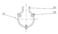
ガスプラグコネクタのさらに別の実例を図9から図11に示す。他の点では前述したものと基本的に同一であるこの実例において、出口ソケット6は、ベース2から離れた先端部の領域において環状溝14を有し、この先端部領域において、図11に示すようなワイヤ状部47は2本の平行屈曲リム50によって位置決めされ、両リムは掛止めスライド41のラッパ状の案内円錐部58内に突出し、該掛止めスライドはその一部についてはスイッチエレメント35のほぞ状突起の取付部40に取り付けられる。幾つかの円柱形ラッチローラ、この場合には3個の円柱形ラッチローラが、ワイヤ状部47の環状部分にネジ止めされる。これらのラッチローラ59は、出口ソケット6の内部に突出する放射状の案内開口部内に配置され、組み立てを容易化するために、好ましくは出口ソケット6の軸方向配向の孔60から形成される。
Further examples of gas plug connectors are shown in FIGS. In this example, which is otherwise essentially the same as described above, the
これらの操作モードは、前記の実施例で説明したものと同様である。 These operation modes are the same as those described in the above embodiment.
漏斗状の案内円錐部58へのリム50の貫通深さに依存して、ワイヤ状部47の直径は、結果としてラッチローラ59の放射状位置が出口ソケット6の縦軸線となるように変更される。これは、遮断バルブ8が開かれるときに、挿入されたガスプラグ57の必要な締め付けを可能とするものである。
Depending on the penetration depth of the
本発明に係るガスプラグコネクタは、勿論、説明した実施例に限定されるものではない。その反対に、変更、変形および組み合わせが、本発明の範囲内で可能である。 Of course, the gas plug connector according to the invention is not limited to the embodiment described. On the contrary, modifications, variations and combinations are possible within the scope of the invention.
例えば、ロッキングデバイスの位置決めおよび/または設計は、保持ボール29の数のように変更することができる。さらに、ガスプラグコネクタは、表面設置取り付けとして知られた変形体のように設計することも可能である。
For example, the positioning and / or design of the locking device can be varied as the number of retaining
1 ハウジング
2 ベース
3 フード
4 ベースプレート
5 入口ソケット
6 出口ソケット
7 チェンバ
8 遮断バルブ
9 弁座
10 軸受
11 プランジャ(第1部分)
12 プランジャ(第2部分)
13 バネエレメント
14 溝
15 バルブヘッド
16 フランジ
17 O−リング
18 バネ
19 ブッシュ
20 バネ
21 フランジ
22 弁座
23 遮断装置
24 閉鎖本体
25 案内アタッチメント
26 閉鎖バネ
27 O−リング
28 案内開口部
29 保持ボール
30 接続開口
31 締付けリング
32 保持バネ
33 内部案内デバイス
34 凹み
35 スイッチエレメント
36 軸受
37 案内デバイス
38 閉込め位置
39 閉込め位置
40 取付部
41 掛止めスライド
42 リム
43 案内デバイス
44 リッジ
45 カーテンウォール
46 頸状部
47 ワイヤ状部
48 留め金
49 長方形孔
50 リム
51 カバー
52 案内路
53 バネ
54 ガイドラグ
55 O−リング
56 延長部
57 ガスプラグ
58 案内円錐部
59 ラッチローラ
60 孔
61 軸受
62 ロッカースイッチ
63 溝
64 開口
65 開口
1
3
12 Plunger (second part)
13
26 Closing spring 27 O-
53
Claims (8)
一方では、該スイッチエレメントは、案内デバイス(37)と適合し、該案内デバイスによってベース(2)に据え付けたプランジャ(11,12)の一端部が支持される一方、その他端部は、遮断バルブ(8)がスイッチエレメント(35)を経てその開放および閉鎖位置に来れるように、ベース(2)のガス導通チェンバ(7)に配置された遮断バルブ(8)のバルブヘッド(15)に連結され、
他方では、回動可能なスイッチエレメント(35)は垂直方向移動または旋回自在なロッキング装置に直接または間接的に連結され、スイッチエレメント(35)の一連の回動の後に、
このロッキング装置を介して締付けリング(31)を軸方向へ移動させることにより、遮断バルブ(8)がその開放位置にあるときに、保持ボール(29)が案内開口部(28)を経て出口ソケット(6)の内部に突出するか、または
このロッキング装置を介してワイヤ状部(47)を内方へ弾性変形させることにより、遮断バルブ(8)がその開放位置にあるときに、ラッチローラ(59)が孔(60)を経て出口ソケット(6)の内部に突出して、ガスプラグ(57)の挿入が防止され、
一方、遮断バルブ(8)がその閉鎖位置にあるときに、保持ボール(29)またはラッチローラ(59)が放射方向の外方へ後退してガスプラグ(57)の挿入を可能とすることを特徴とするガスプラグコネクタ。A housing (1) consisting of a base (2) having an inlet socket (5) to securely connect the gas plug connector to the fixed gas pipe, and a gas plug (57) and a shut-off device (23) in the base (2). An outlet socket (6) for connection, an outlet socket (6) that opens an internal gas passage only when the gas plug (57) is connected after establishing airtightness with the outside, and a gas plug (57) A gas plug connector comprising a hood (3) that covers the connection opening (30) of the outlet socket (6) using a cover (51) when it is cut off, and a base plate (4) that is interconnected as a whole in the housing (1) has a bearing (36) for the switch element (35),
On the one hand, the switch element is fitted with a guide device (37), which supports one end of the plunger (11, 12) mounted on the base (2), while the other end is a shut-off valve. (8) is connected to the valve head (15) of the shut-off valve (8) arranged in the gas conduction chamber (7) of the base (2) so that it can come to its open and closed position via the switch element (35). ,
On the other hand, rotatable switch element (35) is directly or indirectly connected to vertical movement or pivotable locking device, after a series of turning the switch element (35),
By the the locking device clamping ring via a (31) is moved in the axial direction Turkey, when shutoff valve (8) is in its open position, holding the ball (2 9) the guide opening (28) Projecting into the outlet socket (6) via , or
By elastically deforming the wire-like part (47) inward via this locking device, the latch roller (59) passes through the hole (60) through the outlet socket when the shut-off valve (8) is in its open position. (6) projecting into the interior to prevent insertion of the gas plug (57) ,
On the other hand, when the shut-off valve (8) is in its closed position, the holding ball (29) or the latch roller (59) is retracted radially outward to allow the gas plug (57) to be inserted. Characteristic gas plug connector.
Applications Claiming Priority (3)
| Application Number | Priority Date | Filing Date | Title |
|---|---|---|---|
| DE102004028039.8 | 2004-06-09 | ||
| DE102004028039A DE102004028039B3 (en) | 2004-06-09 | 2004-06-09 | Fixed connector to link e.g. a gas cooking oven with a gas supply pipe has a plunger operating in conjunction with a valve |
| PCT/EP2005/006082 WO2005121625A1 (en) | 2004-06-09 | 2005-06-07 | Gas socket |
Publications (2)
| Publication Number | Publication Date |
|---|---|
| JP2008501915A JP2008501915A (en) | 2008-01-24 |
| JP4937123B2 true JP4937123B2 (en) | 2012-05-23 |
Family
ID=34306513
Family Applications (1)
| Application Number | Title | Priority Date | Filing Date |
|---|---|---|---|
| JP2007526271A Expired - Fee Related JP4937123B2 (en) | 2004-06-09 | 2005-06-07 | Gas plug connector |
Country Status (16)
| Country | Link |
|---|---|
| US (1) | US7527071B2 (en) |
| EP (1) | EP1753993B1 (en) |
| JP (1) | JP4937123B2 (en) |
| AR (1) | AR049079A1 (en) |
| AT (1) | ATE393895T1 (en) |
| AU (1) | AU2005252344B2 (en) |
| CA (1) | CA2569110C (en) |
| DE (2) | DE102004028039B3 (en) |
| DK (1) | DK1753993T3 (en) |
| ES (1) | ES2304175T3 (en) |
| HK (1) | HK1100965A1 (en) |
| PL (1) | PL1753993T3 (en) |
| RU (1) | RU2371628C2 (en) |
| SI (1) | SI1753993T1 (en) |
| UA (1) | UA84940C2 (en) |
| WO (1) | WO2005121625A1 (en) |
Families Citing this family (3)
| Publication number | Priority date | Publication date | Assignee | Title |
|---|---|---|---|---|
| DE102006010565B4 (en) * | 2006-03-06 | 2014-09-04 | Viega Gmbh & Co. Kg | Gas socket with lid |
| DE102013221035A1 (en) | 2013-10-17 | 2015-04-23 | Zf Friedrichshafen Ag | Hydraulic control device for an automatic transmission |
| CN113864554A (en) * | 2021-10-20 | 2021-12-31 | 田昌建 | Connection method suitable for connection of different rubber hoses |
Citations (5)
| Publication number | Priority date | Publication date | Assignee | Title |
|---|---|---|---|---|
| JPS5545035A (en) * | 1978-09-26 | 1980-03-29 | Citizen Watch Co Ltd | Tn type liquid crystal display device |
| US4552333A (en) * | 1984-01-27 | 1985-11-12 | Oy Pajakanta Ab | Bayonet catch for a line of pressurized medium |
| JPH0882395A (en) * | 1994-09-09 | 1996-03-26 | Kazuo Yano | Plug-in connection type pipe coupling device with shut-off valve |
| EP0754899A1 (en) * | 1995-07-19 | 1997-01-22 | FIMCIM S.r.l. | Quick-acting connector with shot-off value |
| WO2002048597A1 (en) * | 2000-12-11 | 2002-06-20 | Mertik Maxitrol Gmbh & Co. Kg | Gas socket |
Family Cites Families (10)
| Publication number | Priority date | Publication date | Assignee | Title |
|---|---|---|---|---|
| US4154465A (en) * | 1977-07-15 | 1979-05-15 | Ramer Test Tools, Inc. | Fitting for smooth wall tubes |
| JPS5643591Y2 (en) * | 1978-09-18 | 1981-10-12 | ||
| US4582295A (en) * | 1983-05-04 | 1986-04-15 | Deere & Company | Flow check prevention mechanism |
| DE3725546C2 (en) * | 1987-08-01 | 1994-09-01 | Gok Gmbh & Co Kg | Hose coupling with shut-off valve and anti-twist shut-off valve handle |
| US5020563A (en) * | 1990-06-22 | 1991-06-04 | Gas Research Institute | Connector set |
| US5379794A (en) * | 1994-01-25 | 1995-01-10 | Emerson Electric Co. | Gas control valve having polymeric material body combined with thermally responsive gas shutoff valve having metallic body |
| TW390942B (en) * | 1996-04-22 | 2000-05-21 | Schwinn Cycling & Fitness Inc | Combination pump head |
| DE19746788C1 (en) * | 1997-10-23 | 1999-05-12 | Mertik Maxitrol Gmbh & Co Kg | Gas control valve |
| DE20117126U1 (en) * | 2001-10-23 | 2003-03-20 | Az Industrietechnik Gmbh | Coupling for gas lines |
| DE10312997B3 (en) * | 2003-03-24 | 2004-01-08 | Mertik Maxitrol Gmbh & Co. Kg | gas outlet |
-
2004
- 2004-06-09 DE DE102004028039A patent/DE102004028039B3/en not_active Expired - Fee Related
-
2005
- 2005-06-07 AU AU2005252344A patent/AU2005252344B2/en not_active Ceased
- 2005-06-07 UA UAA200700151A patent/UA84940C2/en unknown
- 2005-06-07 PL PL05747558T patent/PL1753993T3/en unknown
- 2005-06-07 JP JP2007526271A patent/JP4937123B2/en not_active Expired - Fee Related
- 2005-06-07 AT AT05747558T patent/ATE393895T1/en active
- 2005-06-07 RU RU2006143327A patent/RU2371628C2/en not_active IP Right Cessation
- 2005-06-07 DK DK05747558T patent/DK1753993T3/en active
- 2005-06-07 EP EP05747558A patent/EP1753993B1/en not_active Not-in-force
- 2005-06-07 CA CA 2569110 patent/CA2569110C/en not_active Expired - Fee Related
- 2005-06-07 DE DE200550003911 patent/DE502005003911D1/en active Active
- 2005-06-07 ES ES05747558T patent/ES2304175T3/en active Active
- 2005-06-07 WO PCT/EP2005/006082 patent/WO2005121625A1/en active IP Right Grant
- 2005-06-07 US US11/597,997 patent/US7527071B2/en not_active Expired - Fee Related
- 2005-06-07 SI SI200530334T patent/SI1753993T1/en unknown
- 2005-06-09 AR ARP050102353 patent/AR049079A1/en unknown
-
2007
- 2007-06-06 HK HK07105990A patent/HK1100965A1/en not_active IP Right Cessation
Patent Citations (5)
| Publication number | Priority date | Publication date | Assignee | Title |
|---|---|---|---|---|
| JPS5545035A (en) * | 1978-09-26 | 1980-03-29 | Citizen Watch Co Ltd | Tn type liquid crystal display device |
| US4552333A (en) * | 1984-01-27 | 1985-11-12 | Oy Pajakanta Ab | Bayonet catch for a line of pressurized medium |
| JPH0882395A (en) * | 1994-09-09 | 1996-03-26 | Kazuo Yano | Plug-in connection type pipe coupling device with shut-off valve |
| EP0754899A1 (en) * | 1995-07-19 | 1997-01-22 | FIMCIM S.r.l. | Quick-acting connector with shot-off value |
| WO2002048597A1 (en) * | 2000-12-11 | 2002-06-20 | Mertik Maxitrol Gmbh & Co. Kg | Gas socket |
Also Published As
| Publication number | Publication date |
|---|---|
| ATE393895T1 (en) | 2008-05-15 |
| CA2569110A1 (en) | 2005-12-22 |
| AR049079A1 (en) | 2006-06-21 |
| RU2371628C2 (en) | 2009-10-27 |
| AU2005252344A1 (en) | 2005-12-22 |
| US7527071B2 (en) | 2009-05-05 |
| SI1753993T1 (en) | 2008-10-31 |
| DE102004028039B3 (en) | 2005-04-14 |
| PL1753993T3 (en) | 2008-10-31 |
| HK1100965A1 (en) | 2007-10-05 |
| RU2006143327A (en) | 2008-07-20 |
| EP1753993A1 (en) | 2007-02-21 |
| DK1753993T3 (en) | 2008-08-25 |
| JP2008501915A (en) | 2008-01-24 |
| AU2005252344B2 (en) | 2010-02-18 |
| DE502005003911D1 (en) | 2008-06-12 |
| EP1753993B1 (en) | 2008-04-30 |
| WO2005121625A1 (en) | 2005-12-22 |
| CA2569110C (en) | 2012-10-02 |
| UA84940C2 (en) | 2008-12-10 |
| ES2304175T3 (en) | 2008-09-16 |
| US20080078451A1 (en) | 2008-04-03 |
Similar Documents
| Publication | Publication Date | Title |
|---|---|---|
| US4672731A (en) | Ferrule extractor | |
| JP4937123B2 (en) | Gas plug connector | |
| US6945511B2 (en) | Gas socket | |
| US5020563A (en) | Connector set | |
| CN112413206A (en) | Go out wall valve and gas heater | |
| JP5255353B2 (en) | adapter | |
| JP6212324B2 (en) | Gas stopper | |
| JP4639181B2 (en) | Gas socket | |
| CN210423854U (en) | Overflow automatic closing member and double-flow double-control self-closing valve | |
| JP4662558B2 (en) | Gas stopper cover | |
| JP4106024B2 (en) | Gas plug connector | |
| JP4393484B2 (en) | Gas stopper protective cap | |
| JP3676755B2 (en) | Valve device | |
| CN214222136U (en) | Go out wall valve and gas heater | |
| JPH0658443A (en) | Plug type gas coupler | |
| JP2006009906A (en) | Coupling device | |
| KR200266057Y1 (en) | Gas safety valve for domestic use | |
| JP2001208267A (en) | Faucet | |
| JP3930714B2 (en) | Piping joint construction method | |
| JP5800543B2 (en) | Shower elbow and shower faucet with shower elbow | |
| JP4646893B2 (en) | Piping connector | |
| JPS627904Y2 (en) | ||
| JPH0435646Y2 (en) | ||
| KR200316235Y1 (en) | Installation device of fuse cock valve cutoff | |
| CN113565999A (en) | Safety valve |
Legal Events
| Date | Code | Title | Description |
|---|---|---|---|
| A621 | Written request for application examination |
Free format text: JAPANESE INTERMEDIATE CODE: A621 Effective date: 20080423 |
|
| A977 | Report on retrieval |
Free format text: JAPANESE INTERMEDIATE CODE: A971007 Effective date: 20101125 |
|
| A131 | Notification of reasons for refusal |
Free format text: JAPANESE INTERMEDIATE CODE: A131 Effective date: 20101214 |
|
| A521 | Request for written amendment filed |
Free format text: JAPANESE INTERMEDIATE CODE: A523 Effective date: 20110124 |
|
| A131 | Notification of reasons for refusal |
Free format text: JAPANESE INTERMEDIATE CODE: A131 Effective date: 20110607 |
|
| A521 | Request for written amendment filed |
Free format text: JAPANESE INTERMEDIATE CODE: A523 Effective date: 20110725 |
|
| TRDD | Decision of grant or rejection written | ||
| A01 | Written decision to grant a patent or to grant a registration (utility model) |
Free format text: JAPANESE INTERMEDIATE CODE: A01 Effective date: 20120131 |
|
| A01 | Written decision to grant a patent or to grant a registration (utility model) |
Free format text: JAPANESE INTERMEDIATE CODE: A01 |
|
| A61 | First payment of annual fees (during grant procedure) |
Free format text: JAPANESE INTERMEDIATE CODE: A61 Effective date: 20120221 |
|
| FPAY | Renewal fee payment (event date is renewal date of database) |
Free format text: PAYMENT UNTIL: 20150302 Year of fee payment: 3 |
|
| R150 | Certificate of patent or registration of utility model |
Free format text: JAPANESE INTERMEDIATE CODE: R150 |
|
| LAPS | Cancellation because of no payment of annual fees |