JP4934876B2 - Air guide device for automobile - Google Patents
Air guide device for automobile Download PDFInfo
- Publication number
- JP4934876B2 JP4934876B2 JP2001290601A JP2001290601A JP4934876B2 JP 4934876 B2 JP4934876 B2 JP 4934876B2 JP 2001290601 A JP2001290601 A JP 2001290601A JP 2001290601 A JP2001290601 A JP 2001290601A JP 4934876 B2 JP4934876 B2 JP 4934876B2
- Authority
- JP
- Japan
- Prior art keywords
- air guide
- guide device
- rear cover
- operating
- arm
- Prior art date
- Legal status (The legal status is an assumption and is not a legal conclusion. Google has not performed a legal analysis and makes no representation as to the accuracy of the status listed.)
- Expired - Fee Related
Links
Images


Classifications
-
- B—PERFORMING OPERATIONS; TRANSPORTING
- B62—LAND VEHICLES FOR TRAVELLING OTHERWISE THAN ON RAILS
- B62D—MOTOR VEHICLES; TRAILERS
- B62D35/00—Vehicle bodies characterised by streamlining
- B62D35/007—Rear spoilers
-
- Y—GENERAL TAGGING OF NEW TECHNOLOGICAL DEVELOPMENTS; GENERAL TAGGING OF CROSS-SECTIONAL TECHNOLOGIES SPANNING OVER SEVERAL SECTIONS OF THE IPC; TECHNICAL SUBJECTS COVERED BY FORMER USPC CROSS-REFERENCE ART COLLECTIONS [XRACs] AND DIGESTS
- Y02—TECHNOLOGIES OR APPLICATIONS FOR MITIGATION OR ADAPTATION AGAINST CLIMATE CHANGE
- Y02T—CLIMATE CHANGE MITIGATION TECHNOLOGIES RELATED TO TRANSPORTATION
- Y02T10/00—Road transport of goods or passengers
- Y02T10/80—Technologies aiming to reduce greenhouse gasses emissions common to all road transportation technologies
- Y02T10/82—Elements for improving aerodynamics
-
- Y—GENERAL TAGGING OF NEW TECHNOLOGICAL DEVELOPMENTS; GENERAL TAGGING OF CROSS-SECTIONAL TECHNOLOGIES SPANNING OVER SEVERAL SECTIONS OF THE IPC; TECHNICAL SUBJECTS COVERED BY FORMER USPC CROSS-REFERENCE ART COLLECTIONS [XRACs] AND DIGESTS
- Y10—TECHNICAL SUBJECTS COVERED BY FORMER USPC
- Y10S—TECHNICAL SUBJECTS COVERED BY FORMER USPC CROSS-REFERENCE ART COLLECTIONS [XRACs] AND DIGESTS
- Y10S180/00—Motor vehicles
- Y10S180/903—Airstream reactive vehicle or vehicle structure
Description
【0001】
【発明の属する技術分野】
本発明は、自動車、特にスポーツカー用のエアーガイド装置であって、該エアーガイド装置がリヤカバーに隣接して自動車横方向に延びていて、操作装置を用いて休止位置と運転位置との間において可動である形式のものに関する。
【0002】
【従来の技術】
「DE- Porsche Service Information '96」に基づいて公知のこのような形式のエアーガイド装置は、スポーツカーの後部車両領域においてリヤカバーに不動に配置されている。エアーガイド装置の構成に基づいて、スポーツカーのエアロダイナミック的な特性は改善され、特に、後車軸の浮き上がりが防止される。
【0003】
ドイツ連邦共和国特許公開第19741321号明細書に開示された別のエアーガイド装置は、リヤウイングを有しており、このリヤウイングは引き込まれた休止位置と押し出された運転位置との間で可動である。リヤウイングを操作するために働く駆動装置は、車両横方向において互いに間隔をおいて配置された2つのテレスコープ調節装置を有している。両テレスコープ調節装置は、旋回可能なリヤフードに隣接して延びるリヤウイングの下側に係合している。
【0004】
【発明が解決しようとする課題】
本発明の課題は、リヤカバーの領域における、自動車用の調節可能なエアーガイド装置を次のように、すなわちエアーガイド装置が良好なエアロダイナミック的及び動力学的な機能を維持しながら、車体の隣接する構造形状に構造的に容易に組み込むことができるように、形成することである。
【0005】
【課題を解決するための手段】
この課題を解決するために本発明の構成では、冒頭に述べた形式の自動車用エアーガイド装置において、エアーガイド装置が旋回アーム装置を用いてリヤカバーに枢着されており、該旋回アーム装置が、エアーガイド装置を休止位置から運転位置に運動させる操作装置と、分離可能に結合されているようにした。
【0006】
本発明の別の有利な構成は、請求項2以下に記載されている。
【0007】
【発明の効果】
本発明によって得られる大きな利点としては次のことが挙げられる。すなわち本発明によるエアーガイド装置は、空間的に有利に車体に組み込まれており、自動車をエアロダイナミック的に最適化するために役立つ。さらに、リヤカバーにエアーガイド装置が枢着されていることによって、エアーガイド装置を種々異なった位置に運動させるため及び操作装置に所属させるための良好な前提条件が可能になる。この場合リヤカバーとエアーガイド装置とは、前製造された1つのモジュールとしてまとめられていてもよい。旋回アーム装置のばねエレメントは、エアーガイド装置が所望の緊張力をもって操作装置もしくは操作ロッドと共働することを、保証する。操作ロッドに結合された調節装置は、液圧式であっても、空気圧式であっても又は電気式であってもよい。さらにまた、リヤカバーと旋回アーム装置の旋回アームとの間には、ロック装置が設けられており、このロック装置は、エアーガイド装置を休止位置において保持し、これによってエアーガイド装置は走行運転中に休止位置において固定される。
【0008】
【発明の実施の形態】
次に図面を参照しながら本発明の実施の形態を説明する。
【0009】
スポーツカー1として構成された自動車は車体2を有しており、この車体2は車輪3によって支持され、後部近傍の端部領域4にリヤカバー5とエアーガイド装置(Luftleitvorrichtung)6とを有している。このエアーガイド装置6は、スポーツカー1をエアロダイナミック的に最適化するために働き、リヤカバー5の外壁7の上を走行方向に対して横方向A−Aに延びており、サイド部分8,9によって制限されており、この場合エアーガイド装置6は、少なくとも一部の領域において表面がサイド部分8,9に対して同一平面を成すように方向付けられている。さらに、リヤカバー5の外壁7とエアーガイド装置6とは貫流通路10を形成している。
【0010】
エアーガイド装置6のエアロダイナミック的な作用を所望のように使用するために、エアーガイド装置6は、休止位置Rsと運転位置Bsとの間において可動であるように構成されている。そのために、旋回アーム装置12と分離可能に共働する操作装置11が設けられている。旋回アーム装置12を介してエアーガイド装置6は、第1の側13においてヒンジ14を用いてリヤカバー5に枢着されており、これに対して旋回アーム装置12は第2の側15では操作装置11に支持されている。操作装置11は操作ロッド16を有しており、この操作ロッド16には旋回アーム装置12の支持区分17が、分離可能に載っている。旋回アーム装置12にはばねエレメント18が係合作用し、このばねエレメント18は旋回アーム装置12を操作ロッド16に向かって緊張させるように、つまりエアーガイド装置6を休止位置Rsへと運動させるように作用する。ばねエレメント18は脚付きばね19であり、この脚付きばね19はヒンジ14の領域に配置されていて、第1のばねアーム20でリヤカバー区分21に支持され、かつ第2のばねアーム区分20′で旋回アーム装置12に支持されている。
【0011】
操作ロッド16は、例えば液圧式、空気圧式又は電気式である調節装置22の構成部分である。図示の実施例では操作ロッド16はシリンダピストンユニット23のピストンロッドであり、シリンダピストンユニット23はスポーツカー1に鉛直に起立するように配置されていて、ブラケット24を介して車体2に位置固定されている。休止位置Rsから運転位置Bsに又はその逆にエアーガイド装置6を運動させるために、操作ロッド16は方向B−Bにおいて往復動させられる。エアーガイド装置6の旋回アーム装置12は2つの旋回アーム25,26を有しており、両旋回アーム25,26は、スポーツカー1の長手方向中心平面C−Cの両側を延びていて、リヤカバー5の長手方向壁27,28の外側に配置されている。各旋回アーム例えば25は、自由端部29に、エアーガイド装置6のガイドエレメント31のための保持区分30を有しており、ガイドエレメント31はリヤカバー5に対して間隔をおいて延びている。
【0012】
エアーガイド装置6の休止位置Rsにおいてエアーガイド装置6とリヤカバー5との間における相対運動を回避するために、ロック装置31が設けられており、このロック装置31はリヤカバー5の第1の壁区分32と保持区分30の第2の壁区分33との間において作用する。ロック装置31は係止爪34を有しており、この係止爪34はエアーガイド装置6の休止位置Rsにおいて両壁区分32,33を固定する。そのために係止爪34は旋回アーム25の保持区分30に旋回軸線35を用いて支承されており、この場合ばね36は係止爪34をロック位置Sstに回動させようとする。そしてロック位置Sstにおいて係止爪34は壁区分32,33に下から係合する。さらに係止爪34は接触面37で操作ロッド16の支持面38に載っており、係止爪34の旋回軸線35は長手方向中心平面D−Dの外側に位置しているので、操作ロッド16の上昇運動によって係止爪34はロック位置Sstからロック解除位置Estに運動させられる。
【図面の簡単な説明】
【図1】本発明によるエアーガイド装置を備えた自動車を後ろから見た図である。
【図2】エアーガイド装置を備えたリヤカバーを、自動車の斜め上から見た斜視図である。
【図3】エアーガイド装置だけを斜め後ろから見た斜視図である。
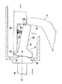
【図4】図2のIV−IV線に沿って断面して示す拡大断面図である。
【符号の説明】
1 スポーツカー、 2 車体、 3 車輪、 4 端部領域、 5 リヤカバー、 6 エアーガイド装置、 7 外壁、 8,9 サイド部分、 10 貫流通路、 11 操作装置、 12 旋回アーム装置、 13 第1の側、 14 ヒンジ、 15 第2の側、 16 操作ロッド、 17 支持区分、 18 ばねエレメント、 19 脚付きばね、 20,20′ ばねアーム、 21 リヤカバー区分、 22 調節装置、 23 シリンダピストンユニット、 24 ブラケット、 25,26 旋回アーム、 27,28 長手方向壁、 29 自由端部、 30 保持区分、 31 ガイドエレメント、ロック装置、 32 第1の壁区分、 33 第2の壁区分、 34 係止爪、 35 旋回軸線、 36 ばね、 37 接触面、 38 支持面[0001]
BACKGROUND OF THE INVENTION
The present invention relates to an air guide device for an automobile, particularly a sports car, the air guide apparatus extending in the lateral direction of the automobile adjacent to the rear cover, and using an operating device between a rest position and a driving position. Concerning a movable type.
[0002]
[Prior art]
Such an air guide device of this type known from “DE-Porsche Service Information '96” is fixedly arranged on the rear cover in the rear vehicle area of the sports car. Based on the configuration of the air guide device, the aerodynamic characteristics of the sports car are improved, and in particular, the rear axle is prevented from lifting.
[0003]
Another air guide device disclosed in German Patent Publication No. 19741321 has a rear wing which is movable between a retracted rest position and an extruded operating position. is there. The drive device that operates to operate the rear wing has two telescope adjustment devices that are spaced apart from each other in the lateral direction of the vehicle. Both telescope adjustment devices are engaged under the rear wing extending adjacent to the pivotable rear hood.
[0004]
[Problems to be solved by the invention]
The object of the present invention is to provide an adjustable air guide device for an automobile in the area of the rear cover as follows, i.e. while the air guide device maintains good aerodynamic and dynamic functions, It is formed so that it can be structurally easily incorporated into the structural shape.
[0005]
[Means for Solving the Problems]
In order to solve this problem, in the configuration of the present invention, in the air guide device for an automobile of the type described at the beginning, the air guide device is pivotally attached to the rear cover using the swing arm device, and the swing arm device is The air guide device is detachably coupled to an operation device that moves the air guide device from the rest position to the operation position.
[0006]
Another advantageous configuration of the invention is described in
[0007]
【Effect of the invention】
The major advantages obtained by the present invention include the following. That is, the air guide device according to the present invention is incorporated in the vehicle body in a spatially advantageous manner, and is useful for aerodynamic optimization of the automobile. Furthermore, the air guide device is pivotally attached to the rear cover, so that good preconditions for moving the air guide device to different positions and for belonging to the operating device are possible. In this case, the rear cover and the air guide device may be combined as one pre-manufactured module. The spring element of the swivel arm device ensures that the air guide device cooperates with the operating device or operating rod with the desired tension. The adjusting device coupled to the operating rod may be hydraulic, pneumatic or electric. Furthermore, a lock device is provided between the rear cover and the swing arm of the swing arm device, and this lock device holds the air guide device in the rest position, so that the air guide device is in a running operation. Fixed in the rest position.
[0008]
DETAILED DESCRIPTION OF THE INVENTION
Next, embodiments of the present invention will be described with reference to the drawings.
[0009]
An automobile configured as a sports car 1 has a
[0010]
In order to use the aerodynamic action of the
[0011]
The
[0012]
In order to avoid relative movement between the
[Brief description of the drawings]
FIG. 1 is a rear view of an automobile equipped with an air guide device according to the present invention.
FIG. 2 is a perspective view of a rear cover provided with an air guide device as viewed obliquely from above an automobile.
FIG. 3 is a perspective view of only the air guide device as viewed obliquely from behind.
4 is an enlarged cross-sectional view taken along the line IV-IV in FIG.
[Explanation of symbols]
DESCRIPTION OF SYMBOLS 1 Sports car, 2 Car body, 3 Wheel, 4 End area | region, 5 Rear cover, 6 Air guide apparatus, 7 Outer wall, 8, 9 Side part, 10 Flow-through path, 11 Operation apparatus, 12 Turning arm apparatus, 13 1st side , 14 Hinge, 15 Second side, 16 Operating rod, 17 Support section, 18 Spring element, 19 Spring with leg, 20, 20 'Spring arm, 21 Rear cover section, 22 Adjusting device, 23 Cylinder piston unit, 24 Bracket, 25, 26 swivel arm, 27, 28 longitudinal wall, 29 free end, 30 holding section, 31 guide element, locking device, 32 first wall section, 33 second wall section, 34 locking pawl, 35 swivel Axis, 36 Spring, 37 Contact surface, 38 Support surface
Claims (12)
Applications Claiming Priority (2)
| Application Number | Priority Date | Filing Date | Title |
|---|---|---|---|
| DE10048122A DE10048122B4 (en) | 2000-09-28 | 2000-09-28 | Air guiding device for a motor vehicle |
| DE10048122.1 | 2000-09-28 |
Publications (2)
| Publication Number | Publication Date |
|---|---|
| JP2002160675A JP2002160675A (en) | 2002-06-04 |
| JP4934876B2 true JP4934876B2 (en) | 2012-05-23 |
Family
ID=7657994
Family Applications (1)
| Application Number | Title | Priority Date | Filing Date |
|---|---|---|---|
| JP2001290601A Expired - Fee Related JP4934876B2 (en) | 2000-09-28 | 2001-09-25 | Air guide device for automobile |
Country Status (4)
| Country | Link |
|---|---|
| US (1) | US6655727B2 (en) |
| EP (1) | EP1193166A3 (en) |
| JP (1) | JP4934876B2 (en) |
| DE (1) | DE10048122B4 (en) |
Families Citing this family (11)
| Publication number | Priority date | Publication date | Assignee | Title |
|---|---|---|---|---|
| US6805399B1 (en) * | 2003-09-26 | 2004-10-19 | Allan L. Brown | Vehicle momentum force actuated braking aerostabilizer |
| DE102008005194B4 (en) * | 2008-01-18 | 2011-03-17 | Hs Genion Gmbh | Air guiding device of a vehicle |
| DE102008010873A1 (en) * | 2008-02-23 | 2009-08-27 | Dr. Ing. H.C. F. Porsche Aktiengesellschaft | Cowl |
| DE102012009735B3 (en) * | 2011-06-09 | 2012-11-15 | Audi Ag | Vehicle flap i.e. tail gate, for use in automotive industry for temporary closing aperture of body e.g. engine compartment, has air guide device located in operational position and adjusted to rest position during aperture request by user |
| DE102011053500B4 (en) * | 2011-09-12 | 2022-02-03 | Dr. Ing. H.C. F. Porsche Aktiengesellschaft | Cooling device for a motor vehicle with an extendable rear spoiler and an intercooler |
| DE102012108048A1 (en) * | 2012-07-18 | 2014-01-23 | Dr. Ing. H.C. F. Porsche Aktiengesellschaft | Rear-air guiding device for full rear-motor car i.e. SUV car, has aerofoil arranged in rear area of vehicle body in movable manner, where aerofoil has two outline areas that are rotatable in circumferential direction of aerofoil |
| ITBO20130244A1 (en) * | 2013-05-22 | 2014-11-23 | Federico Bernabei | ANTI-LOAD TRANSFER DEVICE FOR VEHICLES HAVING AT LEAST THREE WHEELS BETWEEN THEM UNFOLDED |
| GB2518611A (en) * | 2013-09-25 | 2015-04-01 | Mclaren Automotive Ltd | Movable aerodynamic device for a vehicle |
| CN104386146A (en) * | 2014-09-30 | 2015-03-04 | 武汉理工大学 | Vehicle air deflector characterized by automatic adjustment of height |
| CN108345755B (en) * | 2018-03-07 | 2021-06-11 | 北京顺恒达汽车电子股份有限公司 | Method and device for optimally designing strut moment of electric strut system of automobile tail gate |
| DE102019106232B4 (en) * | 2019-03-12 | 2023-09-28 | Dr. Ing. H.C. F. Porsche Aktiengesellschaft | Air guiding device for a motor vehicle body of a motor vehicle |
Family Cites Families (16)
| Publication number | Priority date | Publication date | Assignee | Title |
|---|---|---|---|---|
| US4179154A (en) * | 1977-11-04 | 1979-12-18 | Four Star Corporation | Air velocity responsive deflector |
| IT1153678B (en) * | 1982-12-10 | 1987-01-14 | Alfa Romeo Spa | AUTOMATIC POSITIONING SPOILER FOR A VEHICLE |
| JPS60146747A (en) * | 1984-01-10 | 1985-08-02 | Nissan Motor Co Ltd | Rear baffle device for car |
| JPS60234075A (en) * | 1984-05-02 | 1985-11-20 | Nissan Motor Co Ltd | Air-wing installation structure for car |
| DE3511809A1 (en) * | 1985-03-30 | 1986-10-09 | Dr.Ing.H.C. F. Porsche Ag, 7000 Stuttgart | AIR DUCTING DEVICE ON THE REAR OF A VEHICLE |
| JPS62247984A (en) * | 1986-04-19 | 1987-10-29 | Daikiyoo Bebasuto Kk | Wind flow induction device for automobile |
| JP2580262B2 (en) * | 1988-06-24 | 1997-02-12 | 日産自動車株式会社 | Car rear spoiler device |
| JPH05294264A (en) * | 1992-04-17 | 1993-11-09 | Nippon Plast Co Ltd | Cam movable type rear spoiler |
| US5522637A (en) * | 1994-12-08 | 1996-06-04 | Spears; Dan E. | Auxiliary braking panels for a tractor trailer combination |
| CN1145317A (en) * | 1996-03-06 | 1997-03-19 | 王政中 | Automobile tail choked flow device |
| DE19652692C1 (en) * | 1996-12-18 | 1998-06-10 | Porsche Ag | Motor vehicle, in particular passenger cars |
| DE19741321C2 (en) * | 1997-06-05 | 2002-10-10 | Porsche Ag | Motor vehicle with a rear air guiding device |
| DE19758603C2 (en) | 1997-06-05 | 2001-06-07 | Porsche Ag | Car with spoiler and wing |
| DE19732698C1 (en) * | 1997-07-30 | 1998-07-30 | Webasto Karosseriesysteme | Operating control for vehicle flap preferably rear spoiler |
| DE10016334A1 (en) * | 2000-03-31 | 2001-10-11 | Porsche Ag | Arrangement for controlling the movement of a rear-side air guiding device on motor vehicles |
| KR200203631Y1 (en) * | 2000-06-20 | 2000-11-15 | 윤철균 | Safety device of traveling for a car |
-
2000
- 2000-09-28 DE DE10048122A patent/DE10048122B4/en not_active Expired - Fee Related
-
2001
- 2001-07-06 EP EP01116420A patent/EP1193166A3/en not_active Ceased
- 2001-09-25 JP JP2001290601A patent/JP4934876B2/en not_active Expired - Fee Related
- 2001-09-28 US US09/964,886 patent/US6655727B2/en not_active Expired - Fee Related
Also Published As
| Publication number | Publication date |
|---|---|
| EP1193166A3 (en) | 2003-06-04 |
| DE10048122B4 (en) | 2010-02-04 |
| JP2002160675A (en) | 2002-06-04 |
| US20020041103A1 (en) | 2002-04-11 |
| EP1193166A2 (en) | 2002-04-03 |
| US6655727B2 (en) | 2003-12-02 |
| DE10048122A1 (en) | 2002-04-18 |
Similar Documents
| Publication | Publication Date | Title |
|---|---|---|
| JP4934876B2 (en) | Air guide device for automobile | |
| US7823896B2 (en) | Articulated step system for automotive vehicle | |
| CA2299065C (en) | Retractable running board | |
| US7201432B2 (en) | Rear-mounted air guide device for a motor vehicle | |
| CA1210791A (en) | Bumper structure for vehicle having tiltable load carrier member | |
| JP2008540221A (en) | Vehicle air guide device | |
| US3763789A (en) | Convertible rail-highway vehicle | |
| CN114940220A (en) | Spoiler assembly for vehicle and vehicle | |
| JPH0858637A (en) | Air guide apparatus provided at rear range of car | |
| TW200410894A (en) | Vehicle lifting platform used in maintenance | |
| CN217895082U (en) | Lifting arm assembly and straight arm type aerial work platform convenient to transport | |
| JP2562066B2 (en) | Drying device for the side of vehicle body | |
| CN216761626U (en) | Vehicle pedal | |
| CN217918161U (en) | Spoiler assembly for vehicle and vehicle | |
| JP2002255015A5 (en) | ||
| JP4267778B2 (en) | Tractor | |
| US20230311775A1 (en) | Deployable step systems for motor vehicles | |
| JP2565864Y2 (en) | Rear door opening / closing device | |
| JPH083455Y2 (en) | Snow embankment processing device for snow removal vehicle | |
| ATE278574T1 (en) | SEAT FOR AGRICULTURAL VEHICLES | |
| JPH07197427A (en) | Cleaning device of guard rails on both sides | |
| JP3827223B2 (en) | Composite support mechanism for snow removal equipment | |
| JP3010299U (en) | Vehicle traction coupling device | |
| JP4050965B2 (en) | Telescopic boom type aerial work platform | |
| JP2509522Y2 (en) | Car-only car |
Legal Events
| Date | Code | Title | Description |
|---|---|---|---|
| A711 | Notification of change in applicant |
Free format text: JAPANESE INTERMEDIATE CODE: A712 Effective date: 20080613 |
|
| A621 | Written request for application examination |
Free format text: JAPANESE INTERMEDIATE CODE: A621 Effective date: 20080714 |
|
| A131 | Notification of reasons for refusal |
Free format text: JAPANESE INTERMEDIATE CODE: A131 Effective date: 20100804 |
|
| A601 | Written request for extension of time |
Free format text: JAPANESE INTERMEDIATE CODE: A601 Effective date: 20101102 |
|
| A521 | Request for written amendment filed |
Free format text: JAPANESE INTERMEDIATE CODE: A523 Effective date: 20101104 |
|
| A602 | Written permission of extension of time |
Free format text: JAPANESE INTERMEDIATE CODE: A602 Effective date: 20101108 |
|
| RD04 | Notification of resignation of power of attorney |
Free format text: JAPANESE INTERMEDIATE CODE: A7424 Effective date: 20101227 |
|
| RD04 | Notification of resignation of power of attorney |
Free format text: JAPANESE INTERMEDIATE CODE: A7424 Effective date: 20101228 |
|
| A131 | Notification of reasons for refusal |
Free format text: JAPANESE INTERMEDIATE CODE: A131 Effective date: 20110414 |
|
| A711 | Notification of change in applicant |
Free format text: JAPANESE INTERMEDIATE CODE: A712 Effective date: 20110425 |
|
| A521 | Request for written amendment filed |
Free format text: JAPANESE INTERMEDIATE CODE: A523 Effective date: 20110707 |
|
| TRDD | Decision of grant or rejection written | ||
| A01 | Written decision to grant a patent or to grant a registration (utility model) |
Free format text: JAPANESE INTERMEDIATE CODE: A01 Effective date: 20120106 |
|
| A01 | Written decision to grant a patent or to grant a registration (utility model) |
Free format text: JAPANESE INTERMEDIATE CODE: A01 |
|
| A521 | Request for written amendment filed |
Free format text: JAPANESE INTERMEDIATE CODE: A821 Effective date: 20120207 |
|
| RD02 | Notification of acceptance of power of attorney |
Free format text: JAPANESE INTERMEDIATE CODE: A7422 Effective date: 20120207 |
|
| RD04 | Notification of resignation of power of attorney |
Free format text: JAPANESE INTERMEDIATE CODE: A7424 Effective date: 20120207 |
|
| A61 | First payment of annual fees (during grant procedure) |
Free format text: JAPANESE INTERMEDIATE CODE: A61 Effective date: 20120203 |
|
| FPAY | Renewal fee payment (event date is renewal date of database) |
Free format text: PAYMENT UNTIL: 20150302 Year of fee payment: 3 |
|
| R150 | Certificate of patent or registration of utility model |
Free format text: JAPANESE INTERMEDIATE CODE: R150 |
|
| R250 | Receipt of annual fees |
Free format text: JAPANESE INTERMEDIATE CODE: R250 |
|
| R250 | Receipt of annual fees |
Free format text: JAPANESE INTERMEDIATE CODE: R250 |
|
| LAPS | Cancellation because of no payment of annual fees |