JP4934042B2 - Implantable prosthesis for soft tissue repair - Google Patents
Implantable prosthesis for soft tissue repair Download PDFInfo
- Publication number
- JP4934042B2 JP4934042B2 JP2007532550A JP2007532550A JP4934042B2 JP 4934042 B2 JP4934042 B2 JP 4934042B2 JP 2007532550 A JP2007532550 A JP 2007532550A JP 2007532550 A JP2007532550 A JP 2007532550A JP 4934042 B2 JP4934042 B2 JP 4934042B2
- Authority
- JP
- Japan
- Prior art keywords
- implantable prosthesis
- prosthesis according
- shape
- patch
- layer
- Prior art date
- Legal status (The legal status is an assumption and is not a legal conclusion. Google has not performed a legal analysis and makes no representation as to the accuracy of the status listed.)
- Active
Links
- 210000004872 soft tissue Anatomy 0.000 title description 11
- 230000017423 tissue regeneration Effects 0.000 title description 4
- 230000008439 repair process Effects 0.000 claims description 111
- 239000004744 fabric Substances 0.000 claims description 106
- 230000007547 defect Effects 0.000 claims description 53
- 210000001519 tissue Anatomy 0.000 claims description 49
- 210000003205 muscle Anatomy 0.000 claims description 37
- 230000003014 reinforcing effect Effects 0.000 claims description 20
- 210000000056 organ Anatomy 0.000 claims description 4
- 238000005304 joining Methods 0.000 claims description 3
- 230000002093 peripheral effect Effects 0.000 claims description 3
- 238000007373 indentation Methods 0.000 claims 1
- 239000000463 material Substances 0.000 description 33
- 208000029836 Inguinal Hernia Diseases 0.000 description 26
- 238000000034 method Methods 0.000 description 23
- 210000004267 spermatic cord Anatomy 0.000 description 11
- -1 polypropylene Polymers 0.000 description 10
- 238000003466 welding Methods 0.000 description 9
- 239000004743 Polypropylene Substances 0.000 description 7
- 229920001155 polypropylene Polymers 0.000 description 7
- 230000004888 barrier function Effects 0.000 description 6
- 230000002745 absorbent Effects 0.000 description 5
- 239000002250 absorbent Substances 0.000 description 5
- 239000011148 porous material Substances 0.000 description 5
- 206010019909 Hernia Diseases 0.000 description 4
- 238000002513 implantation Methods 0.000 description 4
- 229920000139 polyethylene terephthalate Polymers 0.000 description 4
- 239000005020 polyethylene terephthalate Substances 0.000 description 4
- 229920001343 polytetrafluoroethylene Polymers 0.000 description 4
- 239000004810 polytetrafluoroethylene Substances 0.000 description 4
- 238000009958 sewing Methods 0.000 description 4
- 239000011230 binding agent Substances 0.000 description 2
- 239000000560 biocompatible material Substances 0.000 description 2
- 230000015572 biosynthetic process Effects 0.000 description 2
- 229920000295 expanded polytetrafluoroethylene Polymers 0.000 description 2
- 230000012010 growth Effects 0.000 description 2
- 210000002837 heart atrium Anatomy 0.000 description 2
- 230000006698 induction Effects 0.000 description 2
- 238000004519 manufacturing process Methods 0.000 description 2
- 238000002844 melting Methods 0.000 description 2
- 230000008018 melting Effects 0.000 description 2
- 239000000203 mixture Substances 0.000 description 2
- 229920001610 polycaprolactone Polymers 0.000 description 2
- 239000004632 polycaprolactone Substances 0.000 description 2
- 230000002787 reinforcement Effects 0.000 description 2
- 206010060954 Abdominal Hernia Diseases 0.000 description 1
- 108010035532 Collagen Proteins 0.000 description 1
- 102000008186 Collagen Human genes 0.000 description 1
- 239000004677 Nylon Substances 0.000 description 1
- 229920000954 Polyglycolide Polymers 0.000 description 1
- 206010060932 Postoperative adhesion Diseases 0.000 description 1
- 239000004792 Prolene Substances 0.000 description 1
- 210000003815 abdominal wall Anatomy 0.000 description 1
- 239000000853 adhesive Substances 0.000 description 1
- 230000001070 adhesive effect Effects 0.000 description 1
- 238000005452 bending Methods 0.000 description 1
- 238000009954 braiding Methods 0.000 description 1
- 229920001436 collagen Polymers 0.000 description 1
- 230000000295 complement effect Effects 0.000 description 1
- 239000002131 composite material Substances 0.000 description 1
- 238000005520 cutting process Methods 0.000 description 1
- 230000004927 fusion Effects 0.000 description 1
- 210000000494 inguinal canal Anatomy 0.000 description 1
- 230000010354 integration Effects 0.000 description 1
- 230000001788 irregular Effects 0.000 description 1
- 238000009940 knitting Methods 0.000 description 1
- 230000007246 mechanism Effects 0.000 description 1
- 238000012986 modification Methods 0.000 description 1
- 230000004048 modification Effects 0.000 description 1
- 238000009740 moulding (composite fabrication) Methods 0.000 description 1
- HLXZNVUGXRDIFK-UHFFFAOYSA-N nickel titanium Chemical compound [Ti].[Ti].[Ti].[Ti].[Ti].[Ti].[Ti].[Ti].[Ti].[Ti].[Ti].[Ni].[Ni].[Ni].[Ni].[Ni].[Ni].[Ni].[Ni].[Ni].[Ni].[Ni].[Ni].[Ni].[Ni] HLXZNVUGXRDIFK-UHFFFAOYSA-N 0.000 description 1
- 229910001000 nickel titanium Inorganic materials 0.000 description 1
- 231100000344 non-irritating Toxicity 0.000 description 1
- 229920001778 nylon Polymers 0.000 description 1
- 238000002355 open surgical procedure Methods 0.000 description 1
- 229920001245 poly(D,L-lactide-co-caprolactone) Polymers 0.000 description 1
- 229920000728 polyester Polymers 0.000 description 1
- 239000004633 polyglycolic acid Substances 0.000 description 1
- 239000004626 polylactic acid Substances 0.000 description 1
- 230000002265 prevention Effects 0.000 description 1
- 230000000717 retained effect Effects 0.000 description 1
- 239000007787 solid Substances 0.000 description 1
- 238000001356 surgical procedure Methods 0.000 description 1
- 108010070228 surgisis Proteins 0.000 description 1
- 238000009941 weaving Methods 0.000 description 1
- 238000004804 winding Methods 0.000 description 1
Images


Classifications
-
- A—HUMAN NECESSITIES
- A61—MEDICAL OR VETERINARY SCIENCE; HYGIENE
- A61F—FILTERS IMPLANTABLE INTO BLOOD VESSELS; PROSTHESES; DEVICES PROVIDING PATENCY TO, OR PREVENTING COLLAPSING OF, TUBULAR STRUCTURES OF THE BODY, e.g. STENTS; ORTHOPAEDIC, NURSING OR CONTRACEPTIVE DEVICES; FOMENTATION; TREATMENT OR PROTECTION OF EYES OR EARS; BANDAGES, DRESSINGS OR ABSORBENT PADS; FIRST-AID KITS
- A61F2/00—Filters implantable into blood vessels; Prostheses, i.e. artificial substitutes or replacements for parts of the body; Appliances for connecting them with the body; Devices providing patency to, or preventing collapsing of, tubular structures of the body, e.g. stents
- A61F2/0063—Implantable repair or support meshes, e.g. hernia meshes
Landscapes
- Health & Medical Sciences (AREA)
- Cardiology (AREA)
- Oral & Maxillofacial Surgery (AREA)
- Transplantation (AREA)
- Engineering & Computer Science (AREA)
- Biomedical Technology (AREA)
- Heart & Thoracic Surgery (AREA)
- Vascular Medicine (AREA)
- Life Sciences & Earth Sciences (AREA)
- Animal Behavior & Ethology (AREA)
- General Health & Medical Sciences (AREA)
- Public Health (AREA)
- Veterinary Medicine (AREA)
- Prostheses (AREA)
Description
発明の分野
本発明は、埋植可能なプロテーゼ、より詳細には軟組織又は筋壁の欠損及び/又は脆弱部を修復又は補強するためのプロテーゼに関する。
The present invention relates to implantable prostheses, and more particularly to prostheses for repairing or reinforcing soft tissue or muscle wall defects and / or fragility.
関連技術の説明
軟組織及び筋壁のヘルニアなどの解剖学的欠損を修復及び補強するための様々な補綴修復材料が知られている。例えば、腹壁ヘルニア及び鼠径ヘルニアは、一般に、ポリプロピレンメッシュ編物(例えば、バードメッシュ(BARD MESH))などの生体適合性布帛のシートを使用して修復される。患者の体内に挿入された後、布帛は、典型的には、欠損の上、欠損の下、又は欠損内の所定の位置に縫合されるか、ステープルで吻合されるか、留め付けられるか、又は他の方法で一時的に固定される。布帛内への組織の内方成長などによる組織と布帛の一体化により、最終的に修復が完了する。
2. Description of Related Art Various prosthetic repair materials are known for repairing and reinforcing anatomical defects such as soft tissue and muscle wall hernias. For example, abdominal wall and inguinal hernias are generally repaired using a sheet of biocompatible fabric, such as a polypropylene mesh knitted fabric (eg, a BARD MESH). After being inserted into the patient's body, the fabric is typically sewn, stapled or clamped in place over the defect, below the defect, or within the defect, Or it is temporarily fixed by other methods. The restoration is finally completed by the integration of the tissue and the fabric, such as by inward growth of the tissue in the fabric.
鼠径ヘルニア修復では、鼠径床の特定のサイズ及び形状に合致するように必要に応じてメッシュ布帛をトリミングしてもよい。間に精索が入るように分離される1対の横方向尾部を形成するように、鼠径管の内側コーナー(medial corner)の反対側にあるメッシュの横方向端部からメッシュの内側端部(medial end)の方にスリットが予め形成されていてもよく、又は、外科医によって作製されてもよい。次いで、尾部を重ね合わせて精索を取り囲み、内鼠径輪(internal ring)を補強してもよい。中に精索が入るように、予め成形されたメッシュにスリットと、スリット端部のキーホールが設けられていてもよい。 In inguinal hernia repair, the mesh fabric may be trimmed as needed to match the specific size and shape of the inguinal floor. The inner edge of the mesh from the lateral edge of the mesh on the opposite side of the medial corner of the inguinal canal to form a pair of lateral tails that are separated so that the spermatic cord is in between ( A slit may be pre-formed towards the media end) or may be made by a surgeon. The tail may then be overlaid to surround the spermatic cord and reinforce the internal ring. A slit and a keyhole at the end of the slit may be provided in a pre-shaped mesh so that the spermatic cord can enter.
本発明の目的は、軟組織及び筋壁を修復及び補強するための方法及びプロテーゼを提供することである。 It is an object of the present invention to provide a method and prosthesis for repairing and reinforcing soft tissue and muscle walls.
発明の概要
本発明は、鼠径ヘルニアを含む組織又は筋壁のヘルニアなど解剖学的欠損を修復するための埋植可能なプロテーゼに関する。
SUMMARY OF THE INVENTION The present invention relates to an implantable prosthesis for repairing anatomical defects, such as tissue containing inguinal hernias or muscle wall hernias.
一実施形態では、身体構造の近傍の組織又は筋壁の欠損を修復するための埋植可能なプロテーゼを提供する。埋植可能なプロテーゼは、組織又は筋壁の欠損の少なくとも一部を被覆するように構成及び配置されている本体部分を含む修復布帛のパッチを備える。プロテーゼは、また、パッチの本体部分を実質的に取り囲む部材も備える。支持部材は、離間して中断部を形成する対向する端部を含む。支持部材は、その一部に沿って延び、身体構造に隣接して位置決めされるように構成されている湾入部を更に含む。 In one embodiment, an implantable prosthesis for repairing a tissue or muscle wall defect near a body structure is provided. The implantable prosthesis comprises a patch of repair fabric that includes a body portion configured and arranged to cover at least a portion of a tissue or muscle wall defect. The prosthesis also includes a member that substantially surrounds the body portion of the patch. The support member includes opposing ends that are spaced apart to form an interrupting portion. The support member further includes a bay that extends along a portion thereof and is configured to be positioned adjacent to the body structure.
別の実施形態では、身体構造の近傍の既存の又は生じ得る組織又は筋壁の欠損を修復するための埋植可能なプロテーゼを提供する。埋植可能なプロテーゼは、組織又は筋壁の欠損の少なくとも一部を被覆するように構成及び配置されている本体部分を含む修復布帛のパッチを備える。パッチは、長軸と短軸を有する非円形の形状を有する。プロテーゼは、また、パッチの本体部分を実質的に取り囲む部材を備える。部材は、その一部に沿って延び、身体構造に隣接して位置決めされるように構成されている湾入部を含む。湾入部はパッチの短軸からオフセットしている。 In another embodiment, an implantable prosthesis for repairing an existing or possible tissue or muscle wall defect in the vicinity of a body structure is provided. The implantable prosthesis comprises a patch of repair fabric that includes a body portion configured and arranged to cover at least a portion of a tissue or muscle wall defect. The patch has a non-circular shape having a major axis and a minor axis. The prosthesis also includes a member that substantially surrounds the body portion of the patch. The member includes a bay that extends along a portion thereof and is configured to be positioned adjacent to the body structure. The bay entrance is offset from the short axis of the patch.
更に別の実施形態では、身体構造の近傍の既存の又は生じ得る組織又は筋壁の欠損を修復するための埋植可能なプロテーゼを提供する。埋植可能なプロテーゼは、組織又は筋壁の欠損の少なくとも一部を被覆するように構成及び配置されている本体部分を含む修復布帛のパッチを備える。プロテーゼは、また、パッチの本体部分を実質的に取り囲む部材を備える。支持部材は、その一部に沿って延び、身体構造に隣接して位置決めされるように構成されている単一の湾入部を含む。 In yet another embodiment, an implantable prosthesis is provided for repairing an existing or possible tissue or muscle wall defect near a body structure. The implantable prosthesis comprises a patch of repair fabric that includes a body portion configured and arranged to cover at least a portion of a tissue or muscle wall defect. The prosthesis also includes a member that substantially surrounds the body portion of the patch. The support member includes a single bay that extends along a portion thereof and is configured to be positioned adjacent to the body structure.
別の実施形態では、既存の又は生じ得る組織又は筋壁の欠損を修復するための埋植可能なプロテーゼを提供する。埋植可能なプロテーゼは、組織又は筋壁の欠損の少なくとも一部を被覆するように構成及び配置されている本体部分を含む修復布帛のパッチを備える。プロテーゼは、また、パッチの本体部分を実質的に取り囲む部材を備える。支持部材は、離間して中断部を形成する対向する端部を含む。修復布帛及び支持部材の対向する端部の少なくとも1つは、対向する端部が修復布帛を貫通して突出することを防止するように構成及び配置されている。 In another embodiment, an implantable prosthesis for repairing an existing or possible tissue or muscle wall defect is provided. The implantable prosthesis comprises a patch of repair fabric that includes a body portion configured and arranged to cover at least a portion of a tissue or muscle wall defect. The prosthesis also includes a member that substantially surrounds the body portion of the patch. The support member includes opposing ends that are spaced apart to form an interrupting portion. At least one of the opposing ends of the repair fabric and the support member is configured and arranged to prevent the opposing ends from protruding through the repair fabric.
別の実施形態では、精索及び大腿管近傍の鼠径ヘルニアを修復するための埋植可能なプロテーゼを提供する。埋植可能なプロテーゼは、広がった形状で鼠径ヘルニアの少なくとも一部を被覆するように構成及び配置されている本体部分を含む修復布帛のパッチを備える。プロテーゼは、また、パッチの本体部分を実質的に取り囲み、本体部分を広がった形状に配備及び/又は保持することを助けるリング状部材を備える。リング状部材は、精索が通り本体部分の内部領域に入るように構成及び配置されている中断部を含む。リング状部材は、本体部分が鼠径ヘルニアを被覆しているとき、大腿管が入るように構成及び配置されている湾入部を更に含む。中断部は、湾入部から離間しているパッチの領域に配置されている。 In another embodiment, an implantable prosthesis for repairing an inguinal hernia near the spermatic cord and femoral canal is provided. The implantable prosthesis comprises a patch of repair fabric that includes a body portion configured and arranged to cover at least a portion of an inguinal hernia in an unfolded shape. The prosthesis also includes a ring-shaped member that substantially surrounds the body portion of the patch and helps to deploy and / or hold the body portion in an unfolded shape. The ring-shaped member includes a break that is constructed and arranged such that the spermatic cord passes through and enters the interior region of the body portion. The ring-shaped member further includes a bay portion that is constructed and arranged to receive the femoral canal when the body portion covers the inguinal hernia. The interruption part is arrange | positioned in the area | region of the patch spaced apart from the bay part.
別の実施形態では、身体構造の近傍の組織又は筋壁の欠損を修復する方法を提供する。本方法は、広がった形状で組織又は筋壁の欠損の少なくとも一部を被覆するように構成及び配置されている本体部分を含む修復布帛のパッチを含む埋植可能なプロテーゼを提供することを含む。プロテーゼは、パッチの本体部分を実質的に取り囲み、本体部分を広がった形状に配備及び/又は保持することを助ける部材を更に含む。部材は、離間して中断部を形成する対向する端部を含む。部材は、その一部に沿って延び、身体構造に隣接して位置決めされるように構成されている湾入部を更に含む。本方法は、また、本体部分が組織又は筋壁の欠損の少なくとも一部を被覆するようにプロテーゼを組織又は筋壁の欠損に埋植する工程、及び、湾入部を身体構造に隣接して位置決めする工程も含む。 In another embodiment, a method of repairing a tissue or muscle wall defect near a body structure is provided. The method includes providing an implantable prosthesis including a patch of repair fabric that includes a body portion configured and arranged to cover at least a portion of a tissue or muscle wall defect in an unfolded shape. . The prosthesis further includes a member that substantially surrounds the body portion of the patch and helps to deploy and / or hold the body portion in an unfolded shape. The member includes opposing ends that are spaced apart to form an interruption. The member further includes a bay that extends along a portion thereof and is configured to be positioned adjacent to the body structure. The method also includes implanting the prosthesis in the tissue or muscle wall defect such that the body portion covers at least a portion of the tissue or muscle wall defect, and positioning the bay adjacent to the body structure. Including the step of.
別の実施形態では、身体構造の近傍の組織又は筋壁の欠損を修復する方法を提供する。本方法は、広がった形状で組織又は筋壁の欠損の少なくとも一部を被覆するように構成及び配置されている本体部分を有する修復布帛のパッチを含む埋植可能なプロテーゼを提供することを含む。プロテーゼは、パッチの本体部分を実質的に取り囲み、本体部分を広がった形状に配備及び/又は保持することを助ける部材を更に含む。部材は、離間して中断部を形成する第1の端部と第2の端部を含む。修復布帛並びに部材の第1及び第2の端部の少なくとも1つは、第1及び第2の端部が修復布帛を貫通して突出することを防止するように構成及び配置されている。本方法は、また、第1の端部と第2の端部の間の中断部を通り本体部分の中に延びるスリットを修復布帛に形成する工程;本体部分が組織又は筋壁の欠損の少なくとも一部を被覆するようにプロテーゼを組織又は筋壁の欠損に埋植する工程;及び、スリットを通るように身体構造を配置する工程を含む。 In another embodiment, a method of repairing a tissue or muscle wall defect near a body structure is provided. The method includes providing an implantable prosthesis comprising a patch of repair fabric having a body portion configured and arranged to cover at least a portion of a tissue or muscle wall defect in an expanded shape. . The prosthesis further includes a member that substantially surrounds the body portion of the patch and helps to deploy and / or hold the body portion in an unfolded shape. The member includes a first end and a second end that are spaced apart to form a break. At least one of the first and second ends of the repair fabric and member is configured and arranged to prevent the first and second ends from protruding through the repair fabric. The method also includes forming a slit in the repair fabric that extends through the interruption between the first end and the second end into the body portion; the body portion is at least of a tissue or muscle wall defect. Implanting a prosthesis in a tissue or muscle wall defect to cover a portion; and positioning a body structure through a slit.
本発明の様々な実施形態は、ある一定の利点を提供し、従来のプロテーゼのある一定の欠点を克服し得る。本発明の実施形態は、同じ利点を共有しない場合があり、同じ利点を共有するものが全ての状況で同じ利点を共有するとは限らない。 Various embodiments of the present invention provide certain advantages and may overcome certain disadvantages of conventional prostheses. Embodiments of the present invention may not share the same advantages, and those who share the same advantages may not share the same advantages in all situations.
ここで、例示として添付の図面を参照し本発明の様々な実施形態を説明する。 Various embodiments of the present invention will now be described by way of example with reference to the accompanying drawings.
詳細な説明
本発明は、解剖学的欠損を修復又は補強するための埋植可能なプロテーゼに関し、軟組織及び筋壁又は他の解剖学的部位の欠損及び脆弱部の修復に特に好適である。理解し易くするため、また本発明の範囲を限定することなく、プロテーゼを以下で特に鼠径ヘルニアの修復に関連して記載する。しかし、当業者には明らかであるように、プロテーゼはそのように限定されず、他の解剖学的処置に使用され得ることを理解すべきである。
DETAILED DESCRIPTION The present invention relates to an implantable prosthesis for repairing or reinforcing an anatomical defect and is particularly suitable for repairing soft tissue and muscle wall or other anatomical defects and fragile sites. For ease of understanding and without limiting the scope of the invention, the prosthesis is described below, particularly in the context of inguinal hernia repair. However, it should be understood that the prosthesis is not so limited and can be used for other anatomical procedures, as will be apparent to those skilled in the art.
本発明は、より詳細には、本体部分を欠損に当てて配置すると開口部又は脆弱部の一部の端から端まで被覆する又は延びるように、欠損又は脆弱部の少なくとも一部より大きい本体部分を有する修復布帛を含むプロテーゼに関する。プロテーゼは、修復布帛を手術部位に配備することを助けるため、及び/又は、修復布帛の折り畳み又は折れ曲がりを防止することを助けるため、修復布帛内又は修復布帛上に配置され得る支持部材などの部材を更に含む。 More particularly, the present invention provides a body portion that is larger than at least a portion of the defect or fragile portion so that when the body portion is placed against the defect, it covers or extends from one end of the opening or the portion of the fragile portion. Prosthesis comprising a repair fabric having The prosthesis is a member, such as a support member, that can be placed in or on the repair fabric to help deploy the repair fabric to the surgical site and / or to prevent the repair fabric from folding or folding. Is further included.
欠損を被覆するため、本体部分を開いた又は広がった形状に配備及び/又は保持することを助けるため、支持部材は、本体部分を、例えば、リング状に実質的に取り囲んでもよい。支持部材は、支持部材が初期形状から変形し、その後、初期形状に戻ってパッチの本体部分を広がった形状に戻すことを可能にする弾性を有してもよい。支持部材は、離間して中断部を形成する第1の端部と第2の端部を含んでもよい。このようにして、中断部を通り本体部分の内部領域に入るキーホール配置などのスリットが修復布帛に容易に形成され得る。スリット及び/又はキーホールは、精索などの索状構造を含む身体構造が入るように構成されていてもよい。しかし、支持部材は本体部分を完全に取り囲み、中断部を含まないように構成され得ることを理解されたい。 To assist in deploying and / or holding the body portion in an open or unfolded shape to cover the defect, the support member may substantially surround the body portion, for example in a ring shape. The support member may have elasticity that allows the support member to deform from the initial shape and then return to the initial shape and return the body portion of the patch to the expanded shape. The support member may include a first end and a second end that are spaced apart to form an interrupting portion. In this manner, a slit such as a keyhole arrangement that passes through the interrupting portion and enters the internal region of the main body portion can be easily formed in the repair fabric. The slit and / or the keyhole may be configured to receive a body structure including a cord-like structure such as a spermatic cord. However, it should be understood that the support member may be configured to completely surround the body portion and not include the interruption.
支持部材は、本体部分の周囲に修復布帛の外周の形状に概ね従うように構成されていてもよい。支持部材の一部は本体部分の方に内側にそり、鼠径ヘルニア修復処置中、大腿管などの身体構造に隣接して位置決めされるように構成されている湾入部又はノッチを形成していてもよい。修復布帛の一部は、支持部材と外周の間に湾入部又はノッチの端から端まで延びてもよい。或いは、湾入部又はノッチに実質的に修復布帛材料がないように、プロテーゼは、修復布帛の外周が支持部材の湾入部の形状に従うように構成されていてもよい。 The support member may be configured to generally follow the shape of the outer periphery of the repair fabric around the body portion. A portion of the support member may sled inwardly toward the body portion to form a bay or notch that is configured to be positioned adjacent to a body structure such as a femoral canal during an inguinal hernia repair procedure. Good. A portion of the repair fabric may extend from end to end of the bay or notch between the support member and the outer periphery. Alternatively, the prosthesis may be configured such that the outer periphery of the repair fabric follows the shape of the bay portion of the support member so that there is substantially no repair fabric material in the bay or notch.
支持部材は、修復部位で特定の構造を収容するようにプロテーゼの一定の領域に配置されている単一の湾入部又はノッチを含んでもよい。大腿管が湾入部に入るように、湾入部は、鼠径ヘルニア修復中、患者の大腿管に隣接して位置決めされる修復布帛のある一定の領域に配置されていてもよい。このようにして、支持部材は、大腿管を回避するように構成されている。 The support member may include a single bay or notch disposed in a region of the prosthesis to accommodate a particular structure at the repair site. The bay can be located in a region of the repair fabric that is positioned adjacent to the patient's femoral canal during inguinal hernia repair so that the femoral canal enters the bay. In this way, the support member is configured to avoid the femoral canal.
プロテーゼは、鼠径ヘルニアを補強又は修復するのに好適な略楕円形(oval)、長円形(elliptical)、又は卵形などの非円形の形状を有してもよい。プロテーゼは、長軸と短軸を有するような形状に作られていてもよい。支持部材は、大腿管などの身体構造を収容するため、プロテーゼの短軸の一方側にオフセットしている湾入部又はノッチを含んでもよい。プロテーゼは、長軸について略対称であり、短軸について略非対称であってもよい。 The prosthesis may have a non-circular shape, such as a generally oval, elliptical, or oval shape suitable for reinforcing or repairing an inguinal hernia. The prosthesis may be made in a shape having a major axis and a minor axis. The support member may include a bay or notch that is offset to one side of the short axis of the prosthesis to accommodate a body structure such as a femoral canal. The prosthesis may be substantially symmetric about the major axis and substantially asymmetric about the minor axis.
支持部材は、2層の布帛材料間に挟持されていてもよい。プロテーゼに使用される材料の量を低減するため、布帛層の1つは、支持部材に従い、支持部材の上に重なる略環状の形状を有してもよい。支持部材及び/又は修復布帛は、中断部の近傍で支持部材の端部が布帛を貫通して突出することを防止するように構成されていてもよい。この点に関して、支持部材の端部は、拡大された頭部又は先端を含んでもよく、支持部材の端部は移動しないように拘束されていてもよく、及び/又は、修復布帛は支持部材の端部の周囲が補強されていてもよい。 The support member may be sandwiched between two layers of fabric material. In order to reduce the amount of material used for the prosthesis, one of the fabric layers may have a generally annular shape that overlies the support member according to the support member. The support member and / or the repair fabric may be configured to prevent the end of the support member from projecting through the fabric in the vicinity of the interruption. In this regard, the end of the support member may include an enlarged head or tip, the end of the support member may be constrained from moving, and / or the repair fabric may be of the support member. The periphery of the end may be reinforced.
修復部位に送達するために修復布帛のサイズを小さくするとき、支持部材は、巻回可能、折り畳み可能、又はその他の方法で畳むことが可能であってもよく、修復部位に配備されると自動的に又は力(例えば、支持体がニチノール(NITINOL)などの形状記憶合材料で形成される場合は、体熱)の影響で初期の拡張した形状に弾性戻りし、プロテーゼが巻き広げられた又は広がった形状を取るように影響を及ぼしてもよい。 When reducing the size of the repair fabric for delivery to the repair site, the support member may be rollable, foldable, or otherwise foldable and automatically when deployed at the repair site. Elastically returned to the initial expanded shape under the influence of force or force (e.g. body heat if the support is formed of a shape memory composite material such as NITINOL), or the prosthesis is unrolled or It may affect to take a widened shape.
修復布帛は、編物などの組織浸潤性材料で形成されていてもよく、又は、中実の若しくは実質的に非多孔質の材料で構成されていてもよい。修復布帛は、1層以上の同じ又は異なる材料で形成されていてもよい。組織浸潤性の部分と非組織浸潤性の他の部分とを有するように修復布帛を形成し、修復デバイスの選択された領域に異なる組織内方成長及び接着防止性(adhesion resistant properties)を提供してもよい。修復布帛は永久又は吸収性材料で形成されていてもよい。 The repair fabric may be formed of a tissue infiltrating material such as a knitted fabric, or may be composed of a solid or substantially non-porous material. The repair fabric may be formed of one or more layers of the same or different materials. The repair fabric is formed to have a tissue invasive part and another non-tissue invasive part, providing different tissue ingrowth and adhesion prevention properties to selected areas of the repair device May be. The restoration fabric may be formed of a permanent or absorbent material.
支持部材は、所望の形状に予め形成されたモノフィラメントで形成されていてもよい。支持部材は、非吸収性又は吸収性の材料で構成されていてもよい。 The support member may be formed of a monofilament previously formed in a desired shape. The support member may be made of a non-absorbable or absorbent material.
プロテーゼは、切開手術処置を使用して、又は腹腔鏡下でカニューレを通して欠損にデバイスを達せしめることによって欠損位に配置されてもよい。修復布帛を欠損位に送達するのに好適な細長い形状に折り畳むこと、巻回すること、又はその他の方法で畳むことなどによってプロテーゼが小さくなるように、修復布帛は可撓性であってもよい。送達すると、修復布帛は巻き広げられた若しくは広がった形状に自動的に開いてもよく、又は、脆弱部若しくは欠損を修復するのに好適な巻き広げられた若しくは広がった形状に外科医によって展開されるか、巻き解かれるか、若しくはその他の方法で配備されてもよい。 The prosthesis may be placed in the defect position using an open surgical procedure or by laparoscopically passing the device through the cannula. The repair fabric may be flexible so that the prosthesis is reduced, such as by folding, winding, or otherwise folding into a suitable elongated shape to deliver the repair fabric to the defect position. . Upon delivery, the repair fabric may automatically open into an unrolled or unfolded shape, or may be deployed by the surgeon into an unrolled or unfolded shape suitable for repairing a weakened portion or defect. Or unrolled or otherwise deployed.
図1〜図2は、鼠径ヘルニアなどの軟組織及び筋壁の欠損を修復又は補強するためのプロテーゼ20の一実施形態を示す。
1-2 illustrate one embodiment of a
プロテーゼ20は、欠損の少なくとも一部を被覆するように構成されている本体部分22を有する埋植可能な生体適合性材料の修復布帛を含む。図示されているように、プロテーゼは、アンダーレイ又はオーバーレイとして使用され得るパッチとして構成されている。当業者に明らかであるように、プロテーゼは、任意の所望の強度、可撓性、組織一体化、接着防止性、及び/又は修復に好適な他の特性を有するように構成されていてもよい。プロテーゼをパッチタイプの実施形態に関連して記載するが、プロテーゼは、プラグ、プラグとパッチの組み合わせ、及び、欠損の修繕に好適な他の配置を含んでもよい。
欠損又は脆弱部を被覆するようにパッチを広がった形状に配備することを助けるため、容易に且つ有効に操作され所望の領域に位置決めされ得るように十分な剛性を有するが、しかもなお、パッチを埋植する医師が適切に取り扱いでき、パッチを埋入される患者が耐えられるように十分な可撓性を有するパッチを使用することが望ましい場合がある。剛さと可撓性のバランスを取るため、図1〜図2に示されている例示の一実施形態では、プロテーゼ20は、パッチの一部を補強するため、及びパッチを広がった形状に配備及び/又は保持することを助けるため、支持部材24を含む。支持部材24は任意の好適な方法でパッチに連結されてもよく、本発明はこの点に関して限定されない。好適な取り付け方法としては、以下に詳述するように、縫合、結合、接着剤、及びパッチと修復布帛の一体形成が挙げられるが、これらに限定されない。
Sufficiently stiff so that it can be easily and effectively manipulated and positioned in the desired area to help deploy the patch in an expanded shape to cover the defect or weakness, yet It may be desirable to use a patch that is adequately handled by the implanting physician and that is flexible enough to be tolerated by the patient in which it is implanted. In order to balance stiffness and flexibility, in one exemplary embodiment shown in FIGS. 1-2, the
支持部材24はパッチの安定性に寄与し、パッチを所望の形状に配備し、維持することを可能にする。例えば、支持部材は、折り畳まれた若しくは他の方法で小さくされたプロテーゼが切開又はカニューレにより修復部位に送達された後、パッチを実質的に巻き広げられた又は広がった形状に戻すことを助け得る。この安定性によって、パッチは取り扱い易くなり、パッチの配備及び配置が容易になる。また、この安定性によって、パッチが折り畳まれる、曲がる、又はその他位置がずれる傾向が最小限になる。取り扱い難い、位置がずれる、又は曲がると、埋植術中に追加の手術処置及び/又は追加の固定が必要となり得る。
一実施形態では、支持部材は、パッチの外縁に隣接して位置決めされる実質的に連続的なループ又はリングを含む。例示の実施形態では、支持部材24は、修復布帛の外周縁26から内側に離間している。しかし、本発明はこの点に関して限定されず、支持部材24は周縁に、及び/又はパッチの本体全体にわたって不連続な位置に配置され得ることを理解されたい。
In one embodiment, the support member includes a substantially continuous loop or ring positioned adjacent to the outer edge of the patch. In the illustrated embodiment, the
欠損を被覆するため本体部分22を広がった形状に配備及び/又は保持することを助けるように、支持部材24は本体部分を実質的に取り囲むように構成されていてもよい。支持部材24は、支持部材が初期形状から変形し、その後、初期形状に戻って本体部分を広がった形状に戻すことを可能にする弾性を有してもよい。
The
図示されているように、支持部材24は、離間してプロテーゼの一端で支持部材に中断部32を形成する第1の端部と第2の端部28、30を含んでもよい。このようにして、スリット及び/又はキーホール配置は、支持部材全体の切断を必要とすることなく、中断部32で本体部分22の内部領域に入るように修復布帛に容易に形成され得る。スリット及び/又は開口部は、精索などの索状構造を含む身体構造が入るように構成されていてもよい。しかし、支持部材は本体部分を完全に取り囲み、中断部を含まないように構成され得ることを理解されたい。
As shown, the
ある一定の修復処置では、修復部位の特定の身体構造を収容するように支持部材を構成することが望ましい場合がある。一実施形態では、支持部材は、鼠径ヘルニア修復中、大腿管を回避するように構成されていてもよい。 In certain repair procedures, it may be desirable to configure the support member to accommodate a particular body structure at the repair site. In one embodiment, the support member may be configured to avoid the femoral canal during inguinal hernia repair.
図1〜図2に示されている例示の一実施形態では、支持部材24は特定の身体構造を収容するように構成されている湾入部又はノッチ34を含んでもよい。図示されているように、支持部材24の一部36は、パッチの外周26から離れて内側にそり、湾入部を形成してもよい。本体部分22の周囲に延びる支持部材24全体は、略凸状の湾曲を有してもよく、一方、湾入部34を形成する支持部材の一部36は、略凹状の湾曲を有してもよい。このようにして、プロテーゼが欠損位に埋植されるとき、湾入部34は、身体構造の周囲に延びる湾曲した形状を有してもよい。
In one exemplary embodiment shown in FIGS. 1-2, the
図1に示されている例示の実施形態では、修復布帛のセグメント38は、支持部材24と外周26の間の湾入部34でパッチの領域を占めてもよい。幾つかの場合、外科医は修復処置のためプロテーゼに修復布帛のこのセグメント38を保持することを所望することがある。例えば、外科医は、鼠径ヘルニア修復において大腿管の近傍の組織の内方成長を促進させることが望ましいと考えることがある。他の場合、外科医はプロテーゼから修復布帛のこのセグメントを除去することが望ましいと考えることがある。
In the exemplary embodiment shown in FIG. 1, the
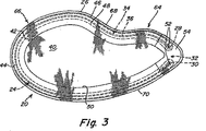
図3に示されている例示の実施形態では、プロテーゼ20は、外科医が余分な布帛材料を除去する必要がないように、パッチの外周26は湾入部34のところが支持部材24の輪郭に従うように構成されていてもよい。
In the exemplary embodiment shown in FIG. 3, the
図1〜図3に示されている例示の実施形態では、支持部材24は、修復処置中、身体構造を収容するための単一の湾入部34を含む。しかし、修復部位で複数の構造を収容するように2つ以上の湾入部を設け得ることを理解されたい。更に、プロテーゼが左側と右側の鼠径ヘルニアの修復などの様々な修復に容易に使用され得るように、支持部材は、パッチ上に対称に位置決めされる1対の湾入部を含んでもよい。しかし、左側と右側の両方の鼠径ヘルニアの修復にプロテーゼを使用するのに、複数の湾入部は必要ではないことを理解されたい。当業者に分かるように、図1〜図3に示されているプロテーゼ20などの単一の湾入部34を有するプロテーゼを、プロテーゼを裏返すことにより左側と右側の両方の鼠径ヘルニアの修復に使用してもよい。
In the exemplary embodiment shown in FIGS. 1-3, the
任意の好適な方法でパッチ上に支持部材24を配置してもよく、本発明はこの点に関して限定されない。一実施形態では、図1〜図4に示されているように、支持部材24は、修復布帛の第1の層と第2の層40、42の間に挟持され、それに物理的に取り付けられていても又は物理的に取り付けられていなくてもよい。第1の層と第2の層40、42の間にあり、第1の層と第2の層を接合させる1対の継ぎ目46、48によって形成されるチャネル44内に支持部材24がきつく又は緩く保持されていてもよい。例示の実施形態では、チャネル44は、支持部材24の輪郭に従う1対の継ぎ目46、48によって形成されている。支持部材24が第1及び第2の層40、42に対して移動しないように、支持部材24の外縁及び内縁に沿って延びる一連のステッチによって継ぎ目46、48を形成してもよい。支持部材24の剛性のため、支持部材の一方側に沿って延びる1つの継ぎ目で十分な場合がある。
本発明は、任意の特定の取り付け方法に限定されず、第1の層と第2の層40、42は他の好適な技術を使用して継ぎ目46、48、又は他の所望の位置に沿って取り付けられ得ることを理解されたい。例えば、層を特定の位置で又は特定のパターンで溶融させること;層を音波溶接、誘導溶接、振動溶接若しくは赤外/レーザー溶接することにより;又は、好適な結合剤を使用することにより、層を一緒に結合させてもよい。当業者に明らかであるように、1つ又は複数の取り付け点は、任意の好適なパターンを有してもよい。
The present invention is not limited to any particular method of attachment, and the first and
或いは、支持部材24は第1の層と第2の層の間に挟持されるのではなく、修復布帛の上又は下に重なってもよく、位置に関わらずステッチ若しくは結合剤で取り付けられても、又は、超音波溶接、誘導溶接、振動溶接、赤外/レーザー溶接等で融着されてもよい。或いは、支持部材24は、層の少なくとも1つを通るように織られてもよく、又は層自体の製造中に一方又は両方の層と一体に形成されてもよい。
Alternatively, the
図1〜図3に示されている例示の一実施形態では、第1の層40は、欠損を被覆するようなサイズ及び形状に作られている布帛材料の完全な層として構成されていてもよい。第2の層42は、プロテーゼの材料の全量が低減するように、支持部材の上に重なり、支持部材の輪郭に概ね従う略環状の形状を有してもよい。図示されているように、第2の層42は、支持部材の輪郭に従うように構成されている内縁50を有する。しかし、第2の層42は第1の層40に対応する布帛材料の完全な層として構成され得ることを理解されたい。外科医が所望する場合、このような配置で更に強度及び/又は組織内方成長が提供されてもよい。また、当業者に理解されるように、このような配置で、埋植術中、プロテーゼの配備及び/又は位置決めを助け得るポケットが層間に形成されてもよい。
In one exemplary embodiment shown in FIGS. 1-3, the
幾つかの場合、支持部材の端部がパッチの修復布帛を貫通して突出することを防止するのが望ましいことがある。この点に関して、支持部材の端部が突出しにくく、修復布帛内に保持されるように、修復布帛及び/又は支持部材を構成してもよい。 In some cases it may be desirable to prevent the end of the support member from protruding through the patch repair fabric. In this regard, the repair fabric and / or the support member may be configured such that the end of the support member is unlikely to protrude and is held within the repair fabric.
例示の一実施形態では、頭部が布帛の細孔を貫通して突出し得る可能性を低減させるように、支持部材24の端部28、30は、布帛の細孔サイズを超える形状又はサイズを有する拡大された頭部を含んでもよい。図1〜図3及び図5に示されているように、布帛の細孔サイズを超えるサイズを有するループを支持部材24の各端部28、30に形成してもよい。また、ループは、支持部材の端部が布帛に及ぼす可能性がある力を分散させることを助け、端部が布帛を貫通して穴を開ける可能性を低減させることに役立ち得る。一実施形態では、支持部材の長さをそれ自体の上に後ろに曲げ、その後、ループ状の部分を支持部材の本体に接合させることによってループを形成してもよい。支持部材の端部に、当業者に明らかな任意の好適な技術を使用して形成される任意の好適な形状を使用し、端部が布帛から突出することを防止し得ることを理解されたい。
In one exemplary embodiment, the ends 28, 30 of the
支持部材の端部の拡大された頭部に加えて、又はその代わりに、端部が布帛から突出することを防止するため、支持部材の移動を拘束するように支持部材を修復布帛に固定してもよい。図5〜図6に示されている例示の一実施形態では、布帛に対する端部の移動を拘束するように、支持部材の各端部28、30を修復布帛に取り付けてもよい。図示されているように、ループを通って延び、布帛層40、42を互いに接合させてループの移動を拘束する1つ以上のステッチ52で、各ループを布帛に繋止してもよい。当業者に明らかな任意の好適な配置を実施し、ループ状の端部の移動を拘束し得ることを理解されたい。例えば、支持部材のループ状の端部28、30内で布帛の層40、42を互いに超音波溶接、溶融、機械的に固定又は結合させてもよい。
In addition to or in place of the enlarged head at the end of the support member, the support member is secured to the repair fabric to constrain movement of the support member to prevent the end from protruding from the fabric. May be. In one exemplary embodiment shown in FIGS. 5-6, each
端部が布帛を貫通して穴を開ける又は突出する可能性を低減させるため、支持部材の端部に隣接する修復布帛を補強することが望ましい場合がある。図1〜図3及び図5〜図6に示されている例示の一実施形態では、中断部32の近傍でパッチに布帛材料の第1及び第2の補強層54、56を追加してもよい。補強層54、56が、布帛の第1及び第2の層40、42の一部の上に重なるように構成され、外側及び内側の継ぎ目46、48がループ状の端部28、30の周囲に延び、層を全て互いに接合させている。端部が修復布帛を貫通して突出する又は穴を開ける可能性を更に低減させるため、このようにして、支持部材の各端部28、30の周囲に補強されたポケットを形成してもよい。補強層は、第1及び第2の層の上に重なるのではなく、第1の層と第2の層の間に挟持され得ることを理解されたい。
It may be desirable to reinforce the repair fabric adjacent the end of the support member to reduce the likelihood that the end will penetrate or protrude through the fabric. In the exemplary embodiment shown in FIGS. 1-3 and 5-6, the first and second reinforcing
図1〜図3及び図5〜図6に示されているプロテーゼの例示の実施形態は、支持部材24の端部28、30の突出を防止する複数の特徴を使用するが、端部の突出を防止するための前述の又は当業者に明らかな他の好適な特徴の任意の1つ又は組み合わせをプロテーゼで実施し得ることを理解されたい。また、プロテーゼは、支持部材の端部の突出を防止する特徴を必要としない場合があること、及び、プロテーゼがこの点に関してそのように限定されないことも理解されたい。
Although the exemplary embodiment of the prosthesis shown in FIGS. 1-3 and 5-6 uses a plurality of features that prevent protrusion of the
プロテーゼは、鼠径ヘルニアなどの特定の欠損の矯正又は修復を容易にすることに導く任意の好適な形状又はサイズを有するように構成されていてもよい。図1〜図3に示されている実施形態では、パッチは比較的平坦な形状を有する。しかし、パッチは平坦である必要はなく、凸状、凹状、凸状/凹状、及び、より複雑な三次元形状も想到される。欠損に送達する時、パッチの操作及び/又はパッチを小さくすることが容易になるように、及び/又はパッチが目的の解剖学的部位に適合するように、パッチは柔軟性があってもよい。 The prosthesis may be configured to have any suitable shape or size that leads to facilitate the correction or repair of certain defects such as inguinal hernias. In the embodiment shown in FIGS. 1-3, the patch has a relatively flat shape. However, the patch need not be flat, and convex, concave, convex / concave, and more complex three-dimensional shapes are contemplated. When delivered to a defect, the patch may be flexible so as to facilitate manipulation of the patch and / or to make the patch small and / or to fit the intended anatomical site. .
図1〜図3に示されている例示の実施形態では、プロテーゼは鼠径管の鼠径ヘルニアを補強又は修復するのに好適な略楕円形、長円形、又は卵形の形状を有する。プロテーゼ20の幾何学的形状は、プロテーゼの最長部分に沿って延びる長軸60と、長軸に垂直な方向でプロテーゼの最大幅部分を横切って延びる短軸62とを有する略長円形である。図1に示されているように、プロテーゼは長軸60について実質的に対称であり、短軸62について実質的に非対称であり、狭い又は鋭形の端部64、広い又は鈍形の端部66、及び、互いの方に鈍形の端部66から鋭形の端部64に向かう方向に集束する対向する側部68、70を有する略エリプソイド形(例えば、卵形)を提供する。プロテーゼは、両方の軸について対称な形状、両方の軸について非対称な形状、又は長軸について非対称で短軸について対称な形状などの、任意の好適な形状を有するように構成され得ることを理解されたい。他の形状の例としては、円形、正方形、長方形、及び不規則な形状が挙げられるが、これらに限定されない。修復布帛は、欠損の一部、又は、好ましくは全部を被覆するようなサイズに作られていてもよい。
In the exemplary embodiment shown in FIGS. 1-3, the prosthesis has a generally oval, oval, or oval shape suitable for reinforcing or repairing an inguinal hernia of an inguinal tube. The geometric shape of the
鈍形の端部66は、鼠径管の内側コーナーなどの修復部位の形状に概ね適合する丸い形状を有する。鈍形の端部66は、欠損の上に重なり、欠損を被覆するように構成されている。プロテーゼの鋭形の端部64は、欠損から離れている修復部位に概ね位置決めされるように構成されている。従って、鋭形の端部は、鈍形の端部と比較してより小さい形状を有し、修復処置中、プロテーゼに投入される材料の全量を低減し得る。しかし、鈍形の端部と鋭形の端部は、当業者に明らかな任意の好適な形状を有し得ることを理解されたい。
The blunt end 66 has a round shape that generally matches the shape of the repair site, such as the inner corner of the inguinal tube. The blunt end 66 is configured to overlap and cover the defect. The
中断部32及び湾入部34は、特定の修復に好適な、本体部分22に対する任意の望ましい位置に位置決めされていてもよい。例示の実施形態では、中断部32は、プロテーゼの鋭形の端部64に長軸60に沿って中心に配置されている。湾入部34は、短軸62からプロテーゼの鋭形の端部64の方にオフセットして位置決めされている。図示されているように、湾入部34は、短軸の一方側に鋭形の端部の方に全部配置されていてもよい。図示されている中断部及び湾入部の実施形態は、鼠径ヘルニアの修復に特に適している。しかし、プロテーゼはそのように限定されず、当業者に明らかであるように、中断部及び/又は湾入部の位置は他の修復に対して様々であってよいことを理解されたい。
The interrupting
前述のように、プロテーゼ20を鼠径ヘルニアの修復に使用してもよい。より詳細には、図1〜図3に示されているプロテーゼは、直接鼠径ヘルニアに特に適している。本体部分22の鈍形の端部は、ヘルニア欠損を覆って配置されるように構成され、湾入部34は大腿管に隣接して位置決めされるように構成されている。前述のように、修復布帛のセグメント38(図1)は、修復のために保持されてもよく又は必要に応じて外科医によって除去されてもよい(図3)。
As described above, the
間接ヘルニア修復の修復では、プロテーゼを修復部位に配置する時、精索を収容するためにプロテーゼにスリット及び/又はキーホール配置が設けられていてもよい。図7に示されている例示の一実施形態では、スリット72は、修復布帛の外周縁26から中断部32を通り、湾入部34に隣接する本体部分の領域の中に内側に延びる。スリットの端部に、精索が入るキーホール開口部74が形成されていてもよい。しかし、キーホール開口部は必要ではなく、精索が入るスリットを単独で設け得ることを理解されたい。スリット72は、プロテーゼの鋭形の端部に、鼠径ヘルニア修復の際に精索が入るように分離され得る1対の尾部を作り出す。しかし、特定の欠損の修復を容易にすることに導く任意の好適な形状を有するようにプロテーゼを構成し得ることを認識されたい。
In indirect hernia repair, when the prosthesis is placed at the repair site, the prosthesis may be provided with a slit and / or keyhole arrangement to accommodate the spermatic cord. In one exemplary embodiment shown in FIG. 7, the slit 72 extends inwardly from the
スリット72及び/又はキーホール開口部74は、プロテーゼに予め形成されていてもよく、又は、修復処置中に外科医によって形成されてもよい。中断部32によって修復布帛にスリットを容易に切り込むことができる。
Slit 72 and / or
鼠径ヘルニア修復のための一実施形態では、プロテーゼ20は、長軸60に沿った長さが約6.29インチ、短軸62に沿った幅が約3.73インチである。中断部の幅は約0.5cm〜約4.0cmであってよい。しかし、これらの寸法は単に例示に過ぎず、当業者に明らかであるように、特定の修復に対して任意の好適なサイズ及び中断部幅を有するようにプロテーゼを構成し得ることを理解されたい。
In one embodiment for inguinal hernia repair, the
修復布帛は、欠損の修復が向上するように組織又は筋肉の内方成長を可能にする又はさもなければそれが起こりやすい、少なくとも1層の組織浸潤性材料を含んでもよい。一実施形態では、第1及び第2の層40、42並びに補強層54、56はそれぞれ、埋植術後、プロテーゼをホスト組織又は筋肉と一体化させるのに十分な組織又は筋肉の内方成長を可能にする複数の間隙又は開口部を含む生体適合性のある可撓性修復材料で形成されている。多層の組織浸潤性布帛は、パッチの強度、及び/又はパッチへの組織の内方成長の量を向上させ得る。好ましくは、第1及び第2の層並びに補強層は、同じ組織浸潤性材料で形成される。しかし、本発明はこの点に関して限定されず、当業者に明らかであるように、いずれか1つの層又は各層を組織又は筋壁の欠損の修復に好適な任意の生体適合性材料で形成してもよい。
The repair fabric may include at least one layer of tissue infiltrating material that allows or otherwise tends to cause tissue or muscle ingrowth to improve defect repair. In one embodiment, the first and
一実施形態では、プロテーゼ20の第1及び第2の層40、42並びに補強層54、56は、それぞれ、厚さが約0.014インチであり、直径約0.0042インチのポリプロピレンモノフィラメントから編まれたポリプロピレンモノフィラメントメッシュ編物のシートから形成されている。ポリプロピレンメッシュは、埋植時に、メッシュ構造の中及び周囲への組織又は筋肉の迅速な内方成長を促進する。或いは、バードメッシュ(BARD MESH)(C.R.バード社(C.R.Bard, Inc.)から入手可能)、ソフトティシューパッチ(SOFT TISSUE PATCH)(微孔質ePTFE−W.L.ゴア・アンド・アソシエーツ社(W.L.Gore & Associates, Inc.)から入手可能)、サージプロ(SURGIPRO)(USサージカル社(U.S. Surgical, Inc.)から入手可能)、トレレックス(TRELEX)(メドックスメディカル(Meadox Medical)から入手可能)、プロレン(PROLENE)及びマーシレン(MERSILENE)(エチコン社(Ethicone,Inc.)から入手可能)、及び、他のメッシュ材料(例えば、アトリウムメディカル社(Atrium Medical Corporation)から入手可能)を含む、組織又は筋肉の補強及び欠損の矯正に好適な他の外科用材料を使用してもよい。ポリグラクチン(ビクリル(VICRYL)−−エチコン社(Ethicon, Inc.)から入手可能)及びポリグリコール酸(デクソン(DEXON)−−USサージカル社(U.S. Surgical, Inc.)から入手可能)を含む吸収性材料は、組織又は筋肉の欠損の一時的な矯正を必要とする用途に好適な場合がある。また、クックバイオメディカル社(Cook Biomedical, Inc.)から入手可能なクックサージシス(COOK SURGISIS)などのコラーゲン材料を使用してもよい。また、マルチフィラメントヤーンからメッシュ布帛を形成し得ること、並びに、編成、製織、編組、及び成形等の任意の好適な方法を使用してメッシュ材料を形成し得ることも想到される。
In one embodiment, the first and
図示されている実施形態では、支持部材24は、所望の弾性度及び剛性度を提供するように、所望の厚さ及び断面形状を有するモノフィラメントを含む。支持部材は、円形、正方形、長方形、三角形、長円形などの任意の断面形状を有し得ることを理解されたい。支持部材はパッチ上に螺旋パターン、正方形パターン、長円形パターン、円形パターン、又は十文字パターン等の任意のパターンで構成されていてもよい。
In the illustrated embodiment, the
支持部材は、特定の修復処置のために必要に応じて非吸収性又は吸収性の材料で形成されていてもよい。一実施形態では、支持部材は、ポリエチレンテレフタレート(PET)からなる非吸収性材料で形成されていてもよい。別の実施形態では、支持部材は、ポリ乳酸(PLA)とポリカプロラクトン(PCL)の70/30のブレンドからなる吸収性材料で形成されていてもよい。しかし、支持部材に望ましい特性を提供するため、当業者に明らかな任意の好適な材料から支持部材を製造し得ることを理解されたい。 The support member may be formed of a non-absorbable or absorbable material as needed for a particular repair procedure. In one embodiment, the support member may be formed of a non-absorbable material made of polyethylene terephthalate (PET). In another embodiment, the support member may be formed of an absorbent material comprising a 70/30 blend of polylactic acid (PLA) and polycaprolactone (PCL). However, it should be understood that the support member may be made from any suitable material that will be apparent to those skilled in the art to provide the desired properties to the support member.
支持部材の剛さ又は剛性はパッチのサイズに応じて様々であってよい。例えば、モノフィラメントの材料の断面径及び/又はばね定数は、所望の剛さを提供するように様々であってよい。 The stiffness or stiffness of the support member may vary depending on the size of the patch. For example, the cross-sectional diameter and / or spring constant of the monofilament material may vary to provide the desired stiffness.
一実施形態では、支持部材は、一定の長さの直径0.042インチの非吸収性ポリエチレンテレフタレート(PET)モノフィラメントから形成されていてもよい。別の実施形態では、支持部材は、一定の長さの直径0.055インチの吸収性PLA/PCLブレンドモノフィラメントから形成されていてもよい。しかし、本発明はこの点に関して限定されず、ナイロン、ポリプロピレン、及びポリエステルを含み、任意の好適な直径又は断面を有する任意の好適な非吸収性及び吸収性材料で支持部材を製造し得ることを理解されたい。 In one embodiment, the support member may be formed of a length of non-absorbable polyethylene terephthalate (PET) monofilament with a 0.042 inch diameter. In another embodiment, the support member may be formed from an absorptive PLA / PCL blend monofilament having a length of 0.055 inches in diameter. However, the present invention is not limited in this regard, and that the support member can be made of any suitable non-absorbable and absorbent material having any suitable diameter or cross section, including nylon, polypropylene, and polyester. I want you to understand.
支持部材24はモノフィラメントで形成されているものとして記載されているが、他の構成を使用してもよい。例えば、支持部材は、後でパッチに取り付けられる又はパッチ上に成形される成形された要素であってもよい。別の例として、支持部材は、修復布帛から形成されてもよい。この点に関して、支持部材は、修復布帛の一部を任意の所望の形状に溶融することにより形成されてもよい。別の例では、支持部材は、例えば、縫取りされたセクションなどの1つ以上の層を通る複数のステッチで形成されてもよい。或いは、支持部材は、所望の補強ゾーンで織目を変化させることによって形成されてもよい。このようにして、組織の内方成長が所望され得る修復布帛の領域は、比較的緩い粗い織目を有するように形成されてもよく、一方、補強領域又は補強ゾーンは、所望の剛性を提供するように比較的緻密な織目を有するように形成されてもよい。支持部材を形成するのに好適な他の方法又は機構を使用してもよく、本発明はこの点に関して限定されない。
Although the
一実施形態では、布帛層は、直径約0.010インチの好適なポリテトラフルオロエチレン(PTFE)モノフィラメントで形成されるステッチを使用して取り付けられていてもよい。PTFEのステッチは、ポリプロピレンモノフィラメントなどの他のステッチ材料を使用するプロテーゼと比較して操作が容易な、より柔軟で、より可撓性のあるプロテーゼを提供し得る。PTFEモノフィラメントでは、材料の低摩擦特性のため、製造プロセスも容易になる。しかし、ポリプロピレンモノフィラメントなどの任意の好適な材料をステッチに使用し得ることを理解されたい。 In one embodiment, the fabric layer may be attached using stitches formed of a suitable polytetrafluoroethylene (PTFE) monofilament having a diameter of about 0.010 inches. PTFE stitching can provide a softer, more flexible prosthesis that is easier to manipulate than prostheses that use other stitch materials such as polypropylene monofilament. PTFE monofilament also facilitates the manufacturing process due to the low friction properties of the material. However, it should be understood that any suitable material such as polypropylene monofilament may be used for stitching.
一実施形態では、第1の又は外側のステッチ線46は、修復布帛の層の周縁から約0.10インチのところに配置されている。第2の又は内側のステッチ線48は、層の周縁から約0.28インチのところに配置されている。支持部材24は、第1のステッチ線と第2のステッチ線46、48の間に形成される0.18インチのチャネル内に保持されている。第1の層と第2の層の取り付けを補うため、第1の層と第2の層40、42の周縁の外側0.07インチがヒートシールされている。
In one embodiment, the first or
ボビンと縫い糸を使用するミシンによって形成される典型的な縫製ステッチを使用して、布帛層40、42、54、56を縫い合わせてもよい。10番のボールポイント針(ball−tipped neadle)を使用して、第1及び第2のステッチ46、48並びに留め付けステッチ(tack stitches)52を形成してもよい。所望のステッチパターンを有するようにプログラムされたコンピュータ制御された台上での縫製手順中、フレームで布帛層を保持してもよい。
Fabric layers 40, 42, 54, 56 may be stitched together using typical sewing stitches formed by a sewing machine using bobbins and sewing threads. A tenth ball-pointed needle may be used to form the first and
ある一定の実施形態では、プロテーゼは、組織、筋肉、又は器官に隣接するところからパッチの1つ以上の縁部を隔離するため、内方成長層の一方側の少なくとも一部、好ましくは全部の上に重なる接着防止性バリア、及び/又は、縁部バリアを含んでもよい。バリア層及び/又は縁部バリアは、実質的に刺激しない材料で、及び/又は構造で形成されていてもよく、ある一定の実施形態では、埋植時に、組織、筋肉、又は器官の内方成長及び接着形成が起こりにくく、それによって内方成長層と、隣接組織、筋肉又は器官との望ましくない術後の接着の発生を低減させ得る。組織内方成長を防止する微孔質の細孔構造を有する発泡ポリテトラフルオロエチレン(ePTFE)のシートを含む当業者に明らかな任意の好適な材料又は構造から、必要に応じて、このようなバリア層及び/又は縁部バリアを形成してもよいが、これらに限定されない。 In certain embodiments, the prosthesis isolates one or more edges of the patch from adjacent to tissue, muscle, or organ, so that at least a portion, preferably all, of one side of the ingrowth layer is present. An overlying anti-adhesion barrier and / or an edge barrier may be included. The barrier layer and / or edge barrier may be formed of a substantially non-irritating material and / or structure, and in certain embodiments, the interior of the tissue, muscle, or organ upon implantation. Growth and adhesion formation is unlikely to occur, thereby reducing the occurrence of unwanted post-operative adhesion between the ingrowth layer and adjacent tissue, muscle or organ. From any suitable material or structure apparent to those skilled in the art including sheets of expanded polytetrafluoroethylene (ePTFE) having a microporous pore structure that prevents tissue ingrowth, such as A barrier layer and / or edge barrier may be formed, but is not limited thereto.
前述の本発明の様々な実施形態の説明は、本発明を説明することを意図したに過ぎず、本発明の他の実施形態、変更、及び均等物は、添付の特許請求の範囲に記載される本発明の範囲に入ることを理解されたい。 The foregoing descriptions of various embodiments of the present invention are merely intended to illustrate the present invention, and other embodiments, modifications, and equivalents of the present invention are set forth in the appended claims. It should be understood that this is within the scope of the present invention.
Claims (43)
前記組織又は筋壁の欠損の少なくとも一部を被覆するように構成及び配置されている本体部分を含む修復布帛のパッチと、
前記パッチの前記本体部分をほぼ取り囲む部材と、を備え、
前記パッチは、外周縁を含み、長軸と短軸を有する非円形の形状を有するとともに、第1の端部と、反対側の第2の端部と、前記第1及び第2の端部の間に延在する第1の側部及び第2の側部と、を含み、前記長軸が前記第1の端部から前記第2の端部へと延在し、
前記部材は、前記パッチの前記第1及び第2の端部の一方に配置され離間して中断部を形成する第1の端部及び第2の端部を含み、
前記部材は、前記身体構造に隣接して位置決めされるように構成されている湾入部を更に含み、
前記湾入部は、前記パッチの前記外周縁から離れて内側にそり前記本体部分に向かう前記部材の部分から形成され、
前記湾入部は、前記中断部から離間して前記パッチの前記第1の側部又は前記第2の側部に沿って配置され、前記中断部に向かう方向へと前記短軸からオフセットしている、
埋植可能なプロテーゼ。An implantable prosthesis for repairing a tissue or muscle wall defect in the vicinity of a body structure,
A patch of repair fabric comprising a body portion configured and arranged to cover at least a portion of the tissue or muscle wall defect;
A member that substantially surrounds the body portion of the patch,
The patch includes an outer peripheral edge, has a non-circular shape having a major axis and a minor axis, and has a first end, an opposite second end, and the first and second ends. A first side and a second side extending between, wherein the major axis extends from the first end to the second end,
The member includes a first end and a second end disposed at one of the first and second ends of the patch and spaced apart to form an interrupting portion;
It said member further seen containing an indentation that is configured to be positioned adjacent to said body structure,
The bay portion is formed from a portion of the member that is sled inward from the outer peripheral edge of the patch and heads toward the main body portion,
The bay portion is arranged along the first side portion or the second side portion of the patch so as to be separated from the interruption portion, and is offset from the short axis in a direction toward the interruption portion. ,
Implantable prosthesis.
請求項1に記載の埋植可能なプロテーゼ。At least one of the first and second ends of the repair fabric and the member is configured and arranged to prevent the first and second ends from protruding through the repair fabric. Being
The implantable prosthesis according to claim 1 .
請求項1又は2に記載の埋植可能なプロテーゼ。The bay portion has a curved shape,
Implantable prosthesis according to claim 1 or 2 .
請求項3に記載の埋植可能なプロテーゼ。The member has a convex shape along a substantial portion thereof, and the bay portion has a concave shape;
The implantable prosthesis according to claim 3 .
請求項1に記載の埋植可能なプロテーゼ。The interrupting portion is located along the long axis;
The implantable prosthesis according to claim 1 .
請求項1から5の何れか一項に記載の埋植可能なプロテーゼ。The patch has a substantially oval shape ;
Implantable prosthesis according to any one of the preceding claims.
請求項6に記載の埋植可能なプロテーゼ。The patch includes a blunt end and a sharp end, the blunt end being larger than the sharp end;
The implantable prosthesis according to claim 6 .
請求項7に記載の埋植可能なプロテーゼ。The bay portion is offset from the short axis towards the sharp end,
8. The implantable prosthesis according to claim 7 .
請求項8に記載の埋植可能なプロテーゼ。The interrupting portion is located along the major axis at the sharp end;
9. The implantable prosthesis according to claim 8 .
請求項1から9の何れか一項に記載の埋植可能なプロテーゼ。The interrupting portion is disposed around the long axis;
Implantable prosthesis according to any one of claims 1 to 9.
請求項1から10の何れか一項に記載の埋植可能なプロテーゼ。The body portion is configured and arranged to cover at least a portion of the tissue or muscle wall defect in an expanded shape;
Implantable prosthesis according to any one of claims 1 to 10.
請求項11に記載の埋植可能なプロテーゼ。The member is configured and arranged to help deploy and / or hold the body portion in an unfolded shape;
12. The implantable prosthesis according to claim 11 .
請求項11又は12に記載の埋植可能なプロテーゼ。The member has an elasticity that allows the member to deform from an initial shape and then return to the initial shape to return the body portion of the patch to the expanded shape.
Implantable prosthesis according to claim 11 or 12 .
請求項1から13の何れか一項に記載の埋植可能なプロテーゼ。The repair fabric includes a first layer and a second layer, and the member is disposed between the first layer and the second layer;
Implantable prosthesis according to any one of claims 1 to 13.
請求項14に記載の埋植可能なプロテーゼ。The member is disposed in a channel defined by an inner seam and an outer seam joining the first layer to the second layer;
The implantable prosthesis according to claim 14 .
請求項14又は15に記載の埋植可能なプロテーゼ。The first layer has a first shape and the second layer has a second shape different from the first shape;
An implantable prosthesis according to claim 14 or 15 .
請求項16に記載の埋植可能なプロテーゼ。The second layer has a substantially annular shape;
The implantable prosthesis according to claim 16 .
請求項17に記載の埋植可能なプロテーゼ。The second layer includes an inner edge that conforms to the shape of the member;
The implantable prosthesis according to claim 17 .
請求項1から18の何れか一項に記載の埋植可能なプロテーゼ。The repair fabric is likely to form a bond with tissues and organs,
Implantable prosthesis according to any one of claims 1 18.
請求項1から19の何れか一項に記載の埋植可能なプロテーゼ。The repair fabric has a plurality of gaps configured and arranged to allow tissue ingrowth;
Implantable prosthesis according to any one of claims 1-19.
請求項1から20の何れか一項に記載の埋植可能なプロテーゼ。The repair fabric comprises at least one mesh fabric;
21. An implantable prosthesis according to any one of claims 1 to 20 .
請求項1から21の何れか一項に記載の埋植可能なプロテーゼ。The member comprises a monofilament;
The implantable prosthesis according to any one of claims 1 to 21 .
請求項2に記載の埋植可能なプロテーゼ。Each of the first and second ends of the member includes an enlarged head configured and arranged to prevent protruding through the repair fabric;
The implantable prosthesis according to claim 2 .
請求項23に記載の埋植可能なプロテーゼ。The first and second ends of the member each include a looped head;
24. The implantable prosthesis according to claim 23 .
請求項2、23、24の何れか一項に記載の埋植可能なプロテーゼ。Each of the first and second ends is constrained to not move relative to the repair fabric;
25. An implantable prosthesis according to any one of claims 2, 23 , 24 .
請求項25に記載の埋植可能なプロテーゼ。Each of the first and second ends is fastened to the repair fabric;
26. The implantable prosthesis according to claim 25 .
請求項25又は26に記載の埋植可能なプロテーゼ。Each of the first and second ends includes a looped head secured to the repair fabric;
27. An implantable prosthesis according to claim 25 or 26 .
請求項23から27の何れか一項に記載の埋植可能なプロテーゼ。The repair fabric is reinforced at portions adjacent to the first and second ends of the member,
28. The implantable prosthesis according to any one of claims 23 to 27 .
請求項28に記載の埋植可能なプロテーゼ。A first reinforcing layer and a second reinforcing layer overlying the first and second ends of the member;
30. The implantable prosthesis according to claim 28 .
請求項29に記載の埋植可能なプロテーゼ。The first reinforcing layer and the second reinforcing layer are disposed on a part of the opposite surface of the restoration fabric;
30. The implantable prosthesis according to claim 29 .
請求項29又は30に記載の埋植可能なプロテーゼ。The repair fabric includes a first layer and a second layer, and the first and second reinforcing layers are disposed on a portion of the first and second layers of the repair fabric;
31. The implantable prosthesis according to claim 29 or 30 .
請求項31に記載の埋植可能なプロテーゼ。The member is disposed between the first layer and the second layer;
32. The implantable prosthesis according to claim 31 .
請求項32に記載の埋植可能なプロテーゼ。The reinforcing layer and the first and second layers are attached to each other with a seam extending around each of the first and second ends;
The implantable prosthesis according to claim 32 .
請求項31から33の何れか一項に記載の埋植可能なプロテーゼ。The reinforcing layer and the first and second layers each include a mesh fabric.
34. An implantable prosthesis according to any one of claims 31 to 33 .
請求項23から34の何れか一項に記載の埋植可能なプロテーゼ。The body portion is configured and arranged to cover at least a portion of the tissue or muscle wall defect in an expanded shape;
35. An implantable prosthesis according to any one of claims 23 to 34 .
請求項35に記載の埋植可能なプロテーゼ。The member is configured and arranged to help deploy and / or hold the body portion in an unfolded shape;
36. The implantable prosthesis according to claim 35 .
請求項35又は36に記載の埋植可能なプロテーゼ。The member has elasticity that allows the member to deform from an initial shape and then return to the initial shape to return the body portion of the patch to the expanded shape.
37. The implantable prosthesis according to claim 35 or 36 .
請求項23から37の何れか一項に記載の埋植可能なプロテーゼ。The member includes a bay portion along a portion thereof, the bay portion configured and arranged to enter a body structure when the patch is placed over the tissue or muscle wall defect.
38. The implantable prosthesis according to any one of claims 23 to 37 .
請求項38に記載の埋植可能なプロテーゼ。The member has a convex shape along a substantial portion thereof, and the bay portion has a concave shape;
39. The implantable prosthesis according to claim 38 .
請求項38又は39に記載の埋植可能なプロテーゼ。The interrupting portion is spaced apart from the bay entrance,
40. The implantable prosthesis according to claim 38 or 39 .
請求項1から40の何れか一項に記載の埋植可能なプロテーゼ。41. An implantable prosthesis according to any one of claims 1 to 40.
請求項1から41の何れか一項に記載の埋植可能なプロテーゼ。42. The implantable prosthesis according to any one of claims 1-41.
前記部材の前記部分の前記第1の端部は、前記長軸に対して直角な方向において前記長軸から第1の距離離れた位置に配置され、前記部材の前記部分の前記第2の端部は、前記長軸に対して直角な方向において前記長軸から第2の距離離れた位置に配置され、The first end of the portion of the member is disposed at a first distance from the major axis in a direction perpendicular to the major axis, and the second end of the portion of the member. The portion is disposed at a position away from the major axis by a second distance in a direction perpendicular to the major axis;
前記湾入部が前記短軸に対して径方向に歪められるように前記第1の距離が前記第2の距離よりも大きくされる、The first distance is larger than the second distance so that the bay portion is distorted in a radial direction with respect to the minor axis;
請求項1から42の何れか一項に記載の埋植可能なプロテーゼ。43. The implantable prosthesis according to any one of claims 1-42.
Applications Claiming Priority (3)
| Application Number | Priority Date | Filing Date | Title |
|---|---|---|---|
| US10/945,532 US8298290B2 (en) | 2004-09-20 | 2004-09-20 | Implantable prosthesis for soft tissue repair |
| US10/945,532 | 2004-09-20 | ||
| PCT/US2005/033334 WO2006034117A1 (en) | 2004-09-20 | 2005-09-19 | Implantable prosthesis for soft tissue repair |
Publications (3)
| Publication Number | Publication Date |
|---|---|
| JP2008513137A JP2008513137A (en) | 2008-05-01 |
| JP2008513137A5 JP2008513137A5 (en) | 2008-11-13 |
| JP4934042B2 true JP4934042B2 (en) | 2012-05-16 |
Family
ID=35709139
Family Applications (1)
| Application Number | Title | Priority Date | Filing Date |
|---|---|---|---|
| JP2007532550A Active JP4934042B2 (en) | 2004-09-20 | 2005-09-19 | Implantable prosthesis for soft tissue repair |
Country Status (6)
| Country | Link |
|---|---|
| US (1) | US8298290B2 (en) |
| EP (1) | EP1796580B1 (en) |
| JP (1) | JP4934042B2 (en) |
| CA (1) | CA2580750C (en) |
| ES (1) | ES2560315T3 (en) |
| WO (1) | WO2006034117A1 (en) |
Cited By (1)
| Publication number | Priority date | Publication date | Assignee | Title |
|---|---|---|---|---|
| JP2011072797A (en) * | 2009-10-01 | 2011-04-14 | Tyco Healthcare Group Lp | Mesh implant |
Families Citing this family (75)
| Publication number | Priority date | Publication date | Assignee | Title |
|---|---|---|---|---|
| US9000040B2 (en) | 2004-09-28 | 2015-04-07 | Atrium Medical Corporation | Cross-linked fatty acid-based biomaterials |
| US8962023B2 (en) | 2004-09-28 | 2015-02-24 | Atrium Medical Corporation | UV cured gel and method of making |
| US9012506B2 (en) | 2004-09-28 | 2015-04-21 | Atrium Medical Corporation | Cross-linked fatty acid-based biomaterials |
| US20060253203A1 (en) * | 2005-05-03 | 2006-11-09 | Alfredo Alvarado | Hernial prosthesis for intraprosthetic fixation |
| US9278161B2 (en) | 2005-09-28 | 2016-03-08 | Atrium Medical Corporation | Tissue-separating fatty acid adhesion barrier |
| US9427423B2 (en) | 2009-03-10 | 2016-08-30 | Atrium Medical Corporation | Fatty-acid based particles |
| US20070265710A1 (en) * | 2006-05-10 | 2007-11-15 | Minnesota Medical Development | Method of making hernia patch and resulting product |
| WO2008021127A2 (en) * | 2006-08-08 | 2008-02-21 | Howmedica Osteonics Corp. | Expandable cartilage implant |
| US7544213B2 (en) * | 2006-09-12 | 2009-06-09 | Adams Jason P | Inflatable hernia patch |
| US20090036996A1 (en) * | 2007-08-03 | 2009-02-05 | Roeber Peter J | Knit PTFE Articles and Mesh |
| US20090187197A1 (en) * | 2007-08-03 | 2009-07-23 | Roeber Peter J | Knit PTFE Articles and Mesh |
| US20110118706A1 (en) * | 2007-08-30 | 2011-05-19 | Proxy Biomedical Limited | Device Suitable for Use During Deployment of a Medical Device |
| JPWO2009050890A1 (en) * | 2007-10-16 | 2011-02-24 | 孝吏 堀 | Sore Hernia Treatment Patch |
| WO2009059005A1 (en) * | 2007-10-31 | 2009-05-07 | Vanderbilt University | Device and method for positioning a surgical prosthesis |
| US9034002B2 (en) | 2008-02-18 | 2015-05-19 | Covidien Lp | Lock bar spring and clip for implant deployment device |
| US9301826B2 (en) | 2008-02-18 | 2016-04-05 | Covidien Lp | Lock bar spring and clip for implant deployment device |
| EP2247245B1 (en) | 2008-02-18 | 2017-06-28 | Covidien LP | A device for deploying and attaching a patch to a biological tissue |
| US9833240B2 (en) | 2008-02-18 | 2017-12-05 | Covidien Lp | Lock bar spring and clip for implant deployment device |
| US9393093B2 (en) | 2008-02-18 | 2016-07-19 | Covidien Lp | Clip for implant deployment device |
| US8758373B2 (en) | 2008-02-18 | 2014-06-24 | Covidien Lp | Means and method for reversibly connecting a patch to a patch deployment device |
| US9398944B2 (en) | 2008-02-18 | 2016-07-26 | Covidien Lp | Lock bar spring and clip for implant deployment device |
| US8317808B2 (en) | 2008-02-18 | 2012-11-27 | Covidien Lp | Device and method for rolling and inserting a prosthetic patch into a body cavity |
| US9393002B2 (en) | 2008-02-18 | 2016-07-19 | Covidien Lp | Clip for implant deployment device |
| US8808314B2 (en) | 2008-02-18 | 2014-08-19 | Covidien Lp | Device and method for deploying and attaching an implant to a biological tissue |
| US9044235B2 (en) | 2008-02-18 | 2015-06-02 | Covidien Lp | Magnetic clip for implant deployment device |
| US8709096B2 (en) * | 2008-04-29 | 2014-04-29 | Proxy Biomedical Limited | Tissue repair implant |
| JP2012501737A (en) * | 2008-09-03 | 2012-01-26 | クック・インコーポレイテッド | Hernia patch with removable elastic element |
| US20100069930A1 (en) * | 2008-09-16 | 2010-03-18 | VentralFix, Inc. | Method and apparatus for minimally invasive delivery, tensioned deployment and fixation of secondary material prosthetic devices in patient body tissue, including hernia repair within the patient's herniation site |
| CA2739034A1 (en) | 2008-10-01 | 2010-04-08 | Enrico Nicolo | Method and apparatus of tension free inguinal hernia repair reconstructing physiology using inguinal hernia prosthetic having lateral non-encircling cord locating structure |
| WO2010039249A1 (en) | 2008-10-03 | 2010-04-08 | C.R. Bard, Inc. | Implantable prosthesis |
| CA2730547C (en) | 2008-10-20 | 2013-08-06 | Polytouch Medical Ltd. | A device for attaching a patch to a biological tissue |
| US20100168856A1 (en) * | 2008-12-31 | 2010-07-01 | Howmedica Osteonics Corp. | Multiple piece tissue void filler |
| US20100168869A1 (en) * | 2008-12-31 | 2010-07-01 | Howmedica Osteonics Corp. | Tissue integration implant |
| US20110038910A1 (en) | 2009-08-11 | 2011-02-17 | Atrium Medical Corporation | Anti-infective antimicrobial-containing biomaterials |
| US8906045B2 (en) | 2009-08-17 | 2014-12-09 | Covidien Lp | Articulating patch deployment device and method of use |
| WO2011021082A1 (en) | 2009-08-17 | 2011-02-24 | PolyTouch Medical, Inc. | Means and method for reversibly connecting an implant to a deployment device |
| WO2012009707A2 (en) | 2010-07-16 | 2012-01-19 | Atrium Medical Corporation | Composition and methods for altering the rate of hydrolysis of cured oil-based materials |
| WO2012047759A1 (en) * | 2010-10-04 | 2012-04-12 | Osteosymbionics, Llc | Soft tissue implant and method of using same |
| CA2817665A1 (en) * | 2010-11-12 | 2012-05-18 | C.R. Bard, Inc. | Fabric prosthesis for repairing a tissue wall defect in proximity of a tube-like structure |
| FR2977789B1 (en) * | 2011-07-13 | 2013-07-19 | Sofradim Production | PROSTHETIC FOR UMBILIC HERNIA |
| PT105907A (en) * | 2011-09-26 | 2013-03-26 | Alrc Tecn E Materiais Cirurgicos Lda Zona Franca Da Madeira | IMPLANTABLE ROLL-OUT PROSTHETICS FOR REPAIR OF ABDOMINAL WALL DEFECTS OR WEAKNESSES |
| WO2013103862A1 (en) | 2012-01-06 | 2013-07-11 | Atrium Medical Corporation | Implantable prosthesis |
| WO2013142353A1 (en) * | 2012-03-22 | 2013-09-26 | C.R. Bard, Inc. | Implantable prosthesis for soft tissue repair |
| US9820839B2 (en) | 2012-04-10 | 2017-11-21 | Ethicon, Inc. | Single plane tissue repair patch having a locating structure |
| US9820837B2 (en) | 2012-04-10 | 2017-11-21 | Ethicon, Inc. | Single plane tissue repair patch |
| US9820838B2 (en) | 2012-04-10 | 2017-11-21 | Ethicon, Inc. | Single plane tissue repair patch |
| US10159552B2 (en) * | 2012-05-01 | 2018-12-25 | C.R. Bard, Inc. | Self adhering implantable mesh prosthesis with reduced insertion profile |
| US9867880B2 (en) | 2012-06-13 | 2018-01-16 | Atrium Medical Corporation | Cured oil-hydrogel biomaterial compositions for controlled drug delivery |
| US9011550B2 (en) | 2012-07-09 | 2015-04-21 | Bard Shannon Limited | Method of mending a groin defect |
| US9173731B2 (en) * | 2012-08-27 | 2015-11-03 | Roderick B. Brown | Segmented hernia patch frame |
| US9498335B2 (en) | 2012-10-02 | 2016-11-22 | Seth McCullen | Implantable devices for musculoskeletal repair and regeneration |
| FR3006578B1 (en) | 2013-06-07 | 2015-05-29 | Sofradim Production | PROSTHESIS BASED ON TEXTILE FOR LAPAROSCOPIC PATHWAY |
| FR3006581B1 (en) * | 2013-06-07 | 2016-07-22 | Sofradim Production | PROSTHESIS BASED ON TEXTILE FOR LAPAROSCOPIC PATHWAY |
| FR3006579B1 (en) * | 2013-06-07 | 2015-07-03 | Sofradim Production | PROSTHETIC FOR LAPAROSCOPIC PATH |
| FR3006580B1 (en) * | 2013-06-07 | 2015-07-17 | Sofradim Production | PROSTHETIC FOR HERNIA |
| DE102014000457B4 (en) | 2014-01-13 | 2018-03-29 | Harald Kobolla | Flat implant for hernia repair with two mesh layers and an elastic, self-expanding expander |
| JP6537520B2 (en) * | 2014-03-06 | 2019-07-03 | シー・アール・バード・インコーポレーテッドC R Bard Incorporated | Hernia repair patch |
| CN103932818B (en) * | 2014-04-08 | 2015-12-16 | 张伟 | A kind of hernia sticking patch gatherer |
| CA2947141C (en) * | 2014-04-30 | 2019-01-15 | Tepha, Inc. | Three-dimensional resorbable implants for tissue reinforcement and hernia repair |
| EP3000433B1 (en) | 2014-09-29 | 2022-09-21 | Sofradim Production | Device for introducing a prosthesis for hernia treatment into an incision and flexible textile based prosthesis |
| EP3000432B1 (en) * | 2014-09-29 | 2022-05-04 | Sofradim Production | Textile-based prosthesis for treatment of inguinal hernia |
| WO2016054463A1 (en) | 2014-10-02 | 2016-04-07 | Mccullen Seth | Anatomically designed meniscus implantable devices |
| EP4039226A1 (en) * | 2014-12-24 | 2022-08-10 | C. R. Bard, Inc. | Implantable prosthesis for soft tissue repair |
| US9693849B2 (en) * | 2015-02-25 | 2017-07-04 | Roderick B. Brown | Hernia patch frame incorporating bio-absorbable material |
| ES2903129T3 (en) * | 2015-03-26 | 2022-03-31 | Bard Inc C R | Force activated grasping device for an implantable prosthesis |
| US9713520B2 (en) * | 2015-06-29 | 2017-07-25 | Ethicon, Inc. | Skirted tissue repair implant having position indication feature |
| AU2016310471B2 (en) * | 2015-08-21 | 2021-05-20 | Lifecell Corporation | Breast treatment device |
| DE102016000376B4 (en) * | 2016-01-15 | 2020-07-23 | Michael Wagner | Flat hernia implant with two mesh layers and an elastic, self-expanding expansion device |
| DE102016000377B4 (en) * | 2016-01-15 | 2020-07-23 | Michael Wagner | Flat hernia implant with a mesh layer and an elastic, self-expanding expansion device |
| CN106821542B (en) * | 2017-02-20 | 2018-10-02 | 周建平 | Holder sticking patch for the repairing of adult inguinal hernia TAPE art formulas |
| EP3618774A4 (en) | 2017-05-02 | 2021-01-27 | McCullen, Seth | Composite joint implant |
| CN108309503A (en) * | 2018-01-29 | 2018-07-24 | 张士丰 | A kind of silicon rubber hernia reparation sticking patch |
| FR3093911B1 (en) | 2019-03-18 | 2021-03-26 | Edouard Pelissier | HERNIA REPAIR PROSTHESIS |
| US11819398B2 (en) * | 2019-03-19 | 2023-11-21 | Children's Hospital Medical Center | Self-expandable surgical implant for correction of congenital diaphragmatic hernia |
| CN110090089A (en) * | 2019-04-28 | 2019-08-06 | 宋大鹏 | Indirect inguinal hernia inner ring seals sticking patch and its application method |
Family Cites Families (117)
| Publication number | Priority date | Publication date | Assignee | Title |
|---|---|---|---|---|
| US27347A (en) * | 1860-03-06 | Improvement in shovel-plows | ||
| US4581A (en) * | 1846-06-16 | Improvement in tuyeres | ||
| US147457A (en) * | 1874-02-10 | Improvement in breech-loading fire-arms | ||
| US103494A (en) * | 1870-05-24 | Jthographefl | ||
| US173804A (en) * | 1876-02-22 | Improvement in railroad-frogs | ||
| US181988A (en) * | 1876-09-05 | Improvement in floating powers | ||
| US87980A (en) * | 1869-03-16 | Improved mode of preparing grain for distillation | ||
| US188350A (en) * | 1877-03-13 | Improvement in wirx fences | ||
| US191538A (en) * | 1877-06-05 | Franz o | ||
| US78602A (en) * | 1868-06-02 | mcmahan | ||
| US49539A (en) * | 1865-08-22 | Improvement in combined rotating fountain and seat for barbers shops | ||
| US130745A (en) * | 1872-08-20 | Improvement in meat-choppers | ||
| US669735A (en) * | 1899-12-16 | 1901-03-12 | Howes Company S | Hulling-machine. |
| US2671444A (en) * | 1951-12-08 | 1954-03-09 | Jr Benjamin F Pease | Nonmetallic mesh surgical insert for hernia repair |
| US3739773A (en) | 1963-10-31 | 1973-06-19 | American Cyanamid Co | Polyglycolic acid prosthetic devices |
| US3463158A (en) | 1963-10-31 | 1969-08-26 | American Cyanamid Co | Polyglycolic acid prosthetic devices |
| US3875937A (en) | 1963-10-31 | 1975-04-08 | American Cyanamid Co | Surgical dressings of absorbable polymers |
| US4892541A (en) | 1982-11-29 | 1990-01-09 | Tascon Medical Technology Corporation | Heart valve prosthesis |
| US4561434A (en) | 1983-09-06 | 1985-12-31 | Standard Textile Co., Inc. | Launderable cloth-like product for surgical use and method of making the same |
| US5032445A (en) | 1984-07-06 | 1991-07-16 | W. L. Gore & Associates | Methods and articles for treating periodontal disease and bone defects |
| US5007916A (en) | 1985-08-22 | 1991-04-16 | Johnson & Johnson Medical, Inc. | Method and material for prevention of surgical adhesions |
| US5002551A (en) | 1985-08-22 | 1991-03-26 | Johnson & Johnson Medical, Inc. | Method and material for prevention of surgical adhesions |
| US4693720A (en) | 1985-09-23 | 1987-09-15 | Katecho, Incorporated | Device for surgically repairing soft tissues and method for making the same |
| US4710192A (en) | 1985-12-30 | 1987-12-01 | Liotta Domingo S | Diaphragm and method for occlusion of the descending thoracic aorta |
| DE3619197A1 (en) | 1986-06-07 | 1987-12-10 | Ethicon Gmbh | UPHOLSTERY IMPLANT |
| US4840626A (en) | 1986-09-29 | 1989-06-20 | Johnson & Johnson Patient Care, Inc. | Heparin-containing adhesion prevention barrier and process |
| US4865026A (en) | 1987-04-23 | 1989-09-12 | Barrett David M | Sealing wound closure device |
| IT1240111B (en) | 1990-02-21 | 1993-11-27 | Sorin Biomedica Spa | SUTURE RING FOR CARDIAC VALVE PROSTHESES |
| US5116357A (en) | 1990-10-11 | 1992-05-26 | Eberbach Mark A | Hernia plug and introducer apparatus |
| US5122155A (en) | 1990-10-11 | 1992-06-16 | Eberbach Mark A | Hernia repair apparatus and method of use |
| US5141515A (en) | 1990-10-11 | 1992-08-25 | Eberbach Mark A | Apparatus and methods for repairing hernias |
| WO1992013500A1 (en) | 1991-02-08 | 1992-08-20 | Surgical Innovations, Inc. | Method and apparatus for repair of inguinal hernias |
| US5254133A (en) | 1991-04-24 | 1993-10-19 | Seid Arnold S | Surgical implantation device and related method of use |
| CA2078530A1 (en) | 1991-09-23 | 1993-03-24 | Jay Erlebacher | Percutaneous arterial puncture seal device and insertion tool therefore |
| US5290217A (en) | 1991-10-10 | 1994-03-01 | Earl K. Sipes | Method and apparatus for hernia repair |
| US5292328A (en) | 1991-10-18 | 1994-03-08 | United States Surgical Corporation | Polypropylene multifilament warp knitted mesh and its use in surgery |
| DK168419B1 (en) | 1991-11-25 | 1994-03-28 | Cook Inc A Cook Group Company | Abdominal wall support device and apparatus for insertion thereof |
| US5258000A (en) | 1991-11-25 | 1993-11-02 | Cook Incorporated | Tissue aperture repair device |
| US5147374A (en) | 1991-12-05 | 1992-09-15 | Alfredo Fernandez | Prosthetic mesh patch for hernia repair |
| DE69334196T2 (en) | 1992-01-21 | 2009-01-02 | Regents Of The University Of Minnesota, Minneapolis | Closure device of a septal defect |
| WO1993017635A1 (en) | 1992-03-04 | 1993-09-16 | C.R. Bard, Inc. | Composite prosthesis and method for limiting the incidence of postoperative adhesions |
| US5766246A (en) | 1992-05-20 | 1998-06-16 | C. R. Bard, Inc. | Implantable prosthesis and method and apparatus for loading and delivering an implantable prothesis |
| US6312442B1 (en) | 1992-06-02 | 2001-11-06 | General Surgical Innovations, Inc. | Method for developing an anatomic space for laparoscopic hernia repair |
| US5972000A (en) * | 1992-11-13 | 1999-10-26 | Influence Medical Technologies, Ltd. | Non-linear anchor inserter device and bone anchors |
| US5725577A (en) | 1993-01-13 | 1998-03-10 | Saxon; Allen | Prosthesis for the repair of soft tissue defects |
| US5743917A (en) | 1993-01-13 | 1998-04-28 | Saxon; Allen | Prosthesis for the repair of soft tissue defects |
| US5356432B1 (en) | 1993-02-05 | 1997-02-04 | Bard Inc C R | Implantable mesh prosthesis and method for repairing muscle or tissue wall defects |
| US5368602A (en) | 1993-02-11 | 1994-11-29 | De La Torre; Roger A. | Surgical mesh with semi-rigid border members |
| US5433996A (en) | 1993-02-18 | 1995-07-18 | W. L. Gore & Associates, Inc. | Laminated patch tissue repair sheet material |
| US5715409A (en) * | 1993-05-24 | 1998-02-03 | I-Tech Corporation | Universal SCSI electrical interface system |
| JP3185906B2 (en) | 1993-11-26 | 2001-07-11 | ニプロ株式会社 | Prosthesis for atrial septal defect |
| US6113623A (en) | 1994-04-20 | 2000-09-05 | Cabinet Beau De Lomenie | Prosthetic device and method for eventration repair |
| FR2719993A1 (en) | 1994-05-20 | 1995-11-24 | Yves Leclerc | Fixing for prosthetic hernia patch |
| FR2720266B1 (en) | 1994-05-27 | 1996-12-20 | Cogent Sarl | Prosthetic fabric. |
| US5634931A (en) | 1994-09-29 | 1997-06-03 | Surgical Sense, Inc. | Hernia mesh patches and methods of their use |
| US5769864A (en) | 1994-09-29 | 1998-06-23 | Surgical Sense, Inc. | Hernia mesh patch |
| US6174320B1 (en) * | 1994-09-29 | 2001-01-16 | Bard Asdi Inc. | Hernia mesh patch with slit |
| US5916225A (en) | 1994-09-29 | 1999-06-29 | Surgical Sense, Inc. | Hernia mesh patch |
| US6280453B1 (en) | 1994-09-29 | 2001-08-28 | Bard Asdi Inc. | Hernia mesh patch with stiffener line segment |
| US6176863B1 (en) | 1994-09-29 | 2001-01-23 | Bard Asdi Inc. | Hernia mesh patch with I-shaped filament |
| US6171318B1 (en) | 1994-09-29 | 2001-01-09 | Bard Asdi Inc. | Hernia mesh patch with stiffening layer |
| US6290708B1 (en) | 1994-09-29 | 2001-09-18 | Bard Asdi Inc. | Hernia mesh patch with seal stiffener |
| IT1275080B (en) | 1994-11-09 | 1997-07-30 | Gabriele Valenti | DYNAMIC PROSTHESIS IN DOUBLE LAYER FOR SURGICAL TREATMENT OF INGUINAL HERNIA |
| US5879366A (en) | 1996-12-20 | 1999-03-09 | W.L. Gore & Associates, Inc. | Self-expanding defect closure device and method of making and using |
| FR2728776B1 (en) | 1994-12-30 | 1997-07-18 | Cogent Sarl | PROSTHETIC ELEMENT FOR THE TREATMENT OF HERNIA OF THE GROWTH, PARTICULARLY BY COELIOSCOPIC |
| FR2735015B1 (en) | 1995-06-12 | 1998-02-13 | Microval | INTERNAL PROSTHESIS IN THE FORM OF A TEXTILE OR OTHER MEDIUM AND ITS COELIOSCOPIC INSERTION APPARATUS |
| FR2735353B1 (en) | 1995-06-16 | 1998-01-23 | Cousin Biotech | FLEXIBLE MEMORY PLATE |
| US5681342A (en) | 1995-08-17 | 1997-10-28 | Benchetrit; Salomon | Device and method for laparoscopic inguinal hernia repair |
| US6113624A (en) | 1995-10-02 | 2000-09-05 | Ethicon, Inc. | Absorbable elastomeric polymer |
| EP0869751A1 (en) | 1995-11-01 | 1998-10-14 | St. Jude Medical, Inc. | Bioresorbable annuloplasty prosthesis |
| WO1997022310A2 (en) | 1995-12-15 | 1997-06-26 | Rangel Gonzalez Neftali | Myopectineal and abdominal hernioprosthesis with self-unfolding device |
| US5876447A (en) | 1996-02-14 | 1999-03-02 | Implantech Associates | Silicone implant for facial plastic surgery |
| WO1997035533A1 (en) | 1996-03-25 | 1997-10-02 | Enrico Nicolo | Surgical mesh prosthetic material and methods of use |
| DE19613730C2 (en) | 1996-03-26 | 2002-08-14 | Ethicon Gmbh | Flat implant for strengthening or closing body tissue |
| US5716408A (en) | 1996-05-31 | 1998-02-10 | C.R. Bard, Inc. | Prosthesis for hernia repair and soft tissue reconstruction |
| US5743914A (en) * | 1996-06-06 | 1998-04-28 | Skiba; Jeffry B. | Bone screw |
| EP0827724A3 (en) | 1996-09-09 | 1998-05-06 | Herniamesh S.r.l. | Prosthesis for hernioplasty with preformed monofilament polypropylene mesh |
| US5716409A (en) | 1996-10-16 | 1998-02-10 | Debbas; Elie | Reinforcement sheet for use in surgical repair |
| FR2754705B1 (en) | 1996-10-18 | 1998-12-18 | Cogent Sarl | ANATOMICAL PROSTHESIS FOR THE REPAIR OF HERNIA BY LAPAROSCOPIC OR OPEN ROUTE |
| FR2762207B1 (en) | 1997-04-17 | 1999-07-30 | Ethnor | IMPROVEMENTS ON SUBCUTANEOUS PROSTHESES FOR BREAST PLASTY |
| US5922026A (en) | 1997-05-01 | 1999-07-13 | Origin Medsystems, Inc. | Surgical method and prosthetic strip therefor |
| US5857467A (en) * | 1997-06-20 | 1999-01-12 | O.R. Solutions, Inc. | Reinforced surgical drapes for use with thermal treatment systems |
| US5824082A (en) * | 1997-07-14 | 1998-10-20 | Brown; Roderick B. | Patch for endoscopic repair of hernias |
| US6066776A (en) | 1997-07-16 | 2000-05-23 | Atrium Medical Corporation | Self-forming prosthesis for repair of soft tissue defects |
| US6241768B1 (en) | 1997-08-27 | 2001-06-05 | Ethicon, Inc. | Prosthetic device for the repair of a hernia |
| US6045576A (en) | 1997-09-16 | 2000-04-04 | Baxter International Inc. | Sewing ring having increased annular coaptation |
| US6090116A (en) | 1997-10-03 | 2000-07-18 | D'aversa; Margaret M. | Knitted surgical mesh |
| FR2769825B1 (en) | 1997-10-22 | 1999-12-03 | Cogent Sarl | PROSTHETIC IMPLANT, ANATOMIC CHANNEL SHUTTER, AND SHUTTER ASSEMBLY COMPRISING SAME |
| USD416327S (en) | 1998-03-25 | 1999-11-09 | Surgical Sense, Inc. | Hernia patch |
| DE69836200T2 (en) | 1998-04-14 | 2007-08-23 | Tranquil Prospects Ltd. | Implant material and process for its preparation |
| US6544167B2 (en) | 1998-05-01 | 2003-04-08 | Correstore, Inc. | Ventricular restoration patch |
| FR2778554B1 (en) | 1998-05-15 | 2000-07-13 | Cousin Biotech | IMPLANTABLE TEXTILE PROSTHESIS |
| US6292708B1 (en) * | 1998-06-11 | 2001-09-18 | Speedfam-Ipec Corporation | Distributed control system for a semiconductor wafer processing machine |
| US6669735B1 (en) * | 1998-07-31 | 2003-12-30 | Davol, Inc. | Prosthesis for surgical treatment of hernia |
| US6166286A (en) | 1998-09-16 | 2000-12-26 | Arcilius Consultadoria E Servicos Lda | Mesh plug kit for the inguinal box surgical technique for hernioplasty |
| US6235869B1 (en) | 1998-10-20 | 2001-05-22 | United States Surgical Corporation | Absorbable polymers and surgical articles fabricated therefrom |
| US6287316B1 (en) | 1999-03-26 | 2001-09-11 | Ethicon, Inc. | Knitted surgical mesh |
| US6174683B1 (en) * | 1999-04-26 | 2001-01-16 | Biocept, Inc. | Method of making biochips and the biochips resulting therefrom |
| US6258124B1 (en) | 1999-05-10 | 2001-07-10 | C. R. Bard, Inc. | Prosthetic repair fabric |
| ES2269069T3 (en) | 1999-06-08 | 2007-04-01 | Ethicon, Inc. | WOVEN SURGICAL MESH. |
| DE60018571T8 (en) | 1999-07-28 | 2006-04-27 | Davol Inc. | HERNIENPROTHESE |
| US6436030B2 (en) | 2000-01-31 | 2002-08-20 | Om P. Rehil | Hiatal hernia repair patch and method for using the same |
| US6425924B1 (en) | 2000-03-31 | 2002-07-30 | Ethicon, Inc. | Hernia repair prosthesis |
| US6610088B1 (en) | 2000-05-03 | 2003-08-26 | Shlomo Gabbay | Biologically covered heart valve prosthesis |
| US6610006B1 (en) | 2000-07-25 | 2003-08-26 | C. R. Bard, Inc. | Implantable prosthesis |
| US7404819B1 (en) | 2000-09-14 | 2008-07-29 | C.R. Bard, Inc. | Implantable prosthesis |
| US6517576B2 (en) | 2000-12-11 | 2003-02-11 | Shlomo Gabbay | Implantable patch prosthesis having one or more cusps for improved competency |
| US20020103494A1 (en) | 2001-01-31 | 2002-08-01 | Pacey John Allen | Percutaneous cannula delvery system for hernia patch |
| DE10121193A1 (en) | 2001-04-30 | 2002-11-28 | Ethicon Gmbh | Flat implant |
| US6575988B2 (en) | 2001-05-15 | 2003-06-10 | Ethicon, Inc. | Deployment apparatus for supple surgical materials |
| ATE278367T1 (en) | 2001-06-11 | 2004-10-15 | Sorin Biomedica Cardio Spa | ANNULOPLASTY PROSTHESIS AND PRODUCTION METHOD THEREOF |
| US20030004581A1 (en) | 2001-06-27 | 2003-01-02 | Rousseau Robert A. | Implantable prosthetic mesh system |
| JP4551088B2 (en) | 2001-09-26 | 2010-09-22 | エドワーズ ライフサイエンシーズ コーポレイション | Thin heart valve suture ring |
| US6800082B2 (en) | 2001-10-19 | 2004-10-05 | Ethicon, Inc. | Absorbable mesh device |
| US6790213B2 (en) * | 2002-01-07 | 2004-09-14 | C.R. Bard, Inc. | Implantable prosthesis |
| US6755868B2 (en) | 2002-03-22 | 2004-06-29 | Ethicon, Inc. | Hernia repair device |
| US7101381B2 (en) | 2002-08-02 | 2006-09-05 | C.R. Bard, Inc. | Implantable prosthesis |
-
2004
- 2004-09-20 US US10/945,532 patent/US8298290B2/en active Active
-
2005
- 2005-09-19 CA CA2580750A patent/CA2580750C/en active Active
- 2005-09-19 WO PCT/US2005/033334 patent/WO2006034117A1/en active Application Filing
- 2005-09-19 EP EP05797946.0A patent/EP1796580B1/en active Active
- 2005-09-19 JP JP2007532550A patent/JP4934042B2/en active Active
- 2005-09-19 ES ES05797946.0T patent/ES2560315T3/en active Active
Cited By (1)
| Publication number | Priority date | Publication date | Assignee | Title |
|---|---|---|---|---|
| JP2011072797A (en) * | 2009-10-01 | 2011-04-14 | Tyco Healthcare Group Lp | Mesh implant |
Also Published As
| Publication number | Publication date |
|---|---|
| EP1796580A1 (en) | 2007-06-20 |
| US8298290B2 (en) | 2012-10-30 |
| WO2006034117A1 (en) | 2006-03-30 |
| CA2580750C (en) | 2014-07-08 |
| ES2560315T3 (en) | 2016-02-18 |
| JP2008513137A (en) | 2008-05-01 |
| CA2580750A1 (en) | 2006-03-30 |
| EP1796580B1 (en) | 2015-10-28 |
| US20060064175A1 (en) | 2006-03-23 |
Similar Documents
| Publication | Publication Date | Title |
|---|---|---|
| JP4934042B2 (en) | Implantable prosthesis for soft tissue repair | |
| JP4425136B2 (en) | Implantable prosthesis | |
| JP5059278B2 (en) | Implantable prosthesis | |
| JP4122294B2 (en) | Implantable prosthesis | |
| US20230000607A1 (en) | Implantable prosthesis for soft tissue repair | |
| EP2344049B1 (en) | Implantable prosthesis |
Legal Events
| Date | Code | Title | Description |
|---|---|---|---|
| A521 | Request for written amendment filed |
Free format text: JAPANESE INTERMEDIATE CODE: A523 Effective date: 20080919 |
|
| A621 | Written request for application examination |
Free format text: JAPANESE INTERMEDIATE CODE: A621 Effective date: 20080919 |
|
| A131 | Notification of reasons for refusal |
Free format text: JAPANESE INTERMEDIATE CODE: A131 Effective date: 20110623 |
|
| A601 | Written request for extension of time |
Free format text: JAPANESE INTERMEDIATE CODE: A601 Effective date: 20110921 |
|
| A602 | Written permission of extension of time |
Free format text: JAPANESE INTERMEDIATE CODE: A602 Effective date: 20110929 |
|
| A521 | Request for written amendment filed |
Free format text: JAPANESE INTERMEDIATE CODE: A523 Effective date: 20111020 |
|
| TRDD | Decision of grant or rejection written | ||
| A01 | Written decision to grant a patent or to grant a registration (utility model) |
Free format text: JAPANESE INTERMEDIATE CODE: A01 Effective date: 20120202 |
|
| A01 | Written decision to grant a patent or to grant a registration (utility model) |
Free format text: JAPANESE INTERMEDIATE CODE: A01 |
|
| A61 | First payment of annual fees (during grant procedure) |
Free format text: JAPANESE INTERMEDIATE CODE: A61 Effective date: 20120217 |
|
| R150 | Certificate of patent or registration of utility model |
Ref document number: 4934042 Country of ref document: JP Free format text: JAPANESE INTERMEDIATE CODE: R150 Free format text: JAPANESE INTERMEDIATE CODE: R150 |
|
| FPAY | Renewal fee payment (event date is renewal date of database) |
Free format text: PAYMENT UNTIL: 20150224 Year of fee payment: 3 |
|
| R250 | Receipt of annual fees |
Free format text: JAPANESE INTERMEDIATE CODE: R250 |
|
| R250 | Receipt of annual fees |
Free format text: JAPANESE INTERMEDIATE CODE: R250 |
|
| R250 | Receipt of annual fees |
Free format text: JAPANESE INTERMEDIATE CODE: R250 |
|
| R250 | Receipt of annual fees |
Free format text: JAPANESE INTERMEDIATE CODE: R250 |
|
| R250 | Receipt of annual fees |
Free format text: JAPANESE INTERMEDIATE CODE: R250 |
|
| R250 | Receipt of annual fees |
Free format text: JAPANESE INTERMEDIATE CODE: R250 |
|
| R250 | Receipt of annual fees |
Free format text: JAPANESE INTERMEDIATE CODE: R250 |
|
| R250 | Receipt of annual fees |
Free format text: JAPANESE INTERMEDIATE CODE: R250 |
|
| R250 | Receipt of annual fees |
Free format text: JAPANESE INTERMEDIATE CODE: R250 |
|
| R250 | Receipt of annual fees |
Free format text: JAPANESE INTERMEDIATE CODE: R250 |