JP4933180B2 - Bag making and packaging machine - Google Patents
Bag making and packaging machine Download PDFInfo
- Publication number
- JP4933180B2 JP4933180B2 JP2006194966A JP2006194966A JP4933180B2 JP 4933180 B2 JP4933180 B2 JP 4933180B2 JP 2006194966 A JP2006194966 A JP 2006194966A JP 2006194966 A JP2006194966 A JP 2006194966A JP 4933180 B2 JP4933180 B2 JP 4933180B2
- Authority
- JP
- Japan
- Prior art keywords
- vertical
- heat sealer
- packaging machine
- bag making
- seal portion
- Prior art date
- Legal status (The legal status is an assumption and is not a legal conclusion. Google has not performed a legal analysis and makes no representation as to the accuracy of the status listed.)
- Active
Links
- 238000004806 packaging method and process Methods 0.000 title claims description 87
- 239000005022 packaging material Substances 0.000 claims description 56
- 230000001105 regulatory effect Effects 0.000 claims description 53
- 238000013459 approach Methods 0.000 claims description 10
- 238000004519 manufacturing process Methods 0.000 claims 1
- 230000007246 mechanism Effects 0.000 description 20
- 238000007789 sealing Methods 0.000 description 19
- 239000000463 material Substances 0.000 description 6
- 229920006280 packaging film Polymers 0.000 description 6
- 239000012785 packaging film Substances 0.000 description 6
- 238000012423 maintenance Methods 0.000 description 4
- 239000004809 Teflon Substances 0.000 description 2
- 229920006362 Teflon® Polymers 0.000 description 2
- 230000005540 biological transmission Effects 0.000 description 2
- 230000015572 biosynthetic process Effects 0.000 description 2
- 230000033001 locomotion Effects 0.000 description 2
- 230000002411 adverse Effects 0.000 description 1
- 238000005452 bending Methods 0.000 description 1
- 238000001816 cooling Methods 0.000 description 1
- 230000002950 deficient Effects 0.000 description 1
- 238000010586 diagram Methods 0.000 description 1
- 230000000694 effects Effects 0.000 description 1
- 230000001788 irregular Effects 0.000 description 1
Images


Classifications
-
- B—PERFORMING OPERATIONS; TRANSPORTING
- B29—WORKING OF PLASTICS; WORKING OF SUBSTANCES IN A PLASTIC STATE IN GENERAL
- B29C—SHAPING OR JOINING OF PLASTICS; SHAPING OF MATERIAL IN A PLASTIC STATE, NOT OTHERWISE PROVIDED FOR; AFTER-TREATMENT OF THE SHAPED PRODUCTS, e.g. REPAIRING
- B29C65/00—Joining or sealing of preformed parts, e.g. welding of plastics materials; Apparatus therefor
- B29C65/02—Joining or sealing of preformed parts, e.g. welding of plastics materials; Apparatus therefor by heating, with or without pressure
- B29C65/18—Joining or sealing of preformed parts, e.g. welding of plastics materials; Apparatus therefor by heating, with or without pressure using heated tools
-
- B—PERFORMING OPERATIONS; TRANSPORTING
- B29—WORKING OF PLASTICS; WORKING OF SUBSTANCES IN A PLASTIC STATE IN GENERAL
- B29C—SHAPING OR JOINING OF PLASTICS; SHAPING OF MATERIAL IN A PLASTIC STATE, NOT OTHERWISE PROVIDED FOR; AFTER-TREATMENT OF THE SHAPED PRODUCTS, e.g. REPAIRING
- B29C66/00—General aspects of processes or apparatus for joining preformed parts
- B29C66/01—General aspects dealing with the joint area or with the area to be joined
- B29C66/02—Preparation of the material, in the area to be joined, prior to joining or welding
- B29C66/024—Thermal pre-treatments
- B29C66/0242—Heating, or preheating, e.g. drying
-
- B—PERFORMING OPERATIONS; TRANSPORTING
- B29—WORKING OF PLASTICS; WORKING OF SUBSTANCES IN A PLASTIC STATE IN GENERAL
- B29C—SHAPING OR JOINING OF PLASTICS; SHAPING OF MATERIAL IN A PLASTIC STATE, NOT OTHERWISE PROVIDED FOR; AFTER-TREATMENT OF THE SHAPED PRODUCTS, e.g. REPAIRING
- B29C66/00—General aspects of processes or apparatus for joining preformed parts
- B29C66/01—General aspects dealing with the joint area or with the area to be joined
- B29C66/05—Particular design of joint configurations
- B29C66/10—Particular design of joint configurations particular design of the joint cross-sections
- B29C66/11—Joint cross-sections comprising a single joint-segment, i.e. one of the parts to be joined comprising a single joint-segment in the joint cross-section
- B29C66/112—Single lapped joints
- B29C66/1122—Single lap to lap joints, i.e. overlap joints
-
- B—PERFORMING OPERATIONS; TRANSPORTING
- B29—WORKING OF PLASTICS; WORKING OF SUBSTANCES IN A PLASTIC STATE IN GENERAL
- B29C—SHAPING OR JOINING OF PLASTICS; SHAPING OF MATERIAL IN A PLASTIC STATE, NOT OTHERWISE PROVIDED FOR; AFTER-TREATMENT OF THE SHAPED PRODUCTS, e.g. REPAIRING
- B29C66/00—General aspects of processes or apparatus for joining preformed parts
- B29C66/01—General aspects dealing with the joint area or with the area to be joined
- B29C66/05—Particular design of joint configurations
- B29C66/10—Particular design of joint configurations particular design of the joint cross-sections
- B29C66/13—Single flanged joints; Fin-type joints; Single hem joints; Edge joints; Interpenetrating fingered joints; Other specific particular designs of joint cross-sections not provided for in groups B29C66/11 - B29C66/12
- B29C66/133—Fin-type joints, the parts to be joined being flexible
-
- B—PERFORMING OPERATIONS; TRANSPORTING
- B29—WORKING OF PLASTICS; WORKING OF SUBSTANCES IN A PLASTIC STATE IN GENERAL
- B29C—SHAPING OR JOINING OF PLASTICS; SHAPING OF MATERIAL IN A PLASTIC STATE, NOT OTHERWISE PROVIDED FOR; AFTER-TREATMENT OF THE SHAPED PRODUCTS, e.g. REPAIRING
- B29C66/00—General aspects of processes or apparatus for joining preformed parts
- B29C66/40—General aspects of joining substantially flat articles, e.g. plates, sheets or web-like materials; Making flat seams in tubular or hollow articles; Joining single elements to substantially flat surfaces
- B29C66/41—Joining substantially flat articles ; Making flat seams in tubular or hollow articles
- B29C66/43—Joining a relatively small portion of the surface of said articles
- B29C66/431—Joining the articles to themselves
- B29C66/4312—Joining the articles to themselves for making flat seams in tubular or hollow articles, e.g. transversal seams
-
- B—PERFORMING OPERATIONS; TRANSPORTING
- B29—WORKING OF PLASTICS; WORKING OF SUBSTANCES IN A PLASTIC STATE IN GENERAL
- B29C—SHAPING OR JOINING OF PLASTICS; SHAPING OF MATERIAL IN A PLASTIC STATE, NOT OTHERWISE PROVIDED FOR; AFTER-TREATMENT OF THE SHAPED PRODUCTS, e.g. REPAIRING
- B29C66/00—General aspects of processes or apparatus for joining preformed parts
- B29C66/40—General aspects of joining substantially flat articles, e.g. plates, sheets or web-like materials; Making flat seams in tubular or hollow articles; Joining single elements to substantially flat surfaces
- B29C66/41—Joining substantially flat articles ; Making flat seams in tubular or hollow articles
- B29C66/43—Joining a relatively small portion of the surface of said articles
- B29C66/432—Joining a relatively small portion of the surface of said articles for making tubular articles or closed loops, e.g. by joining several sheets ; for making hollow articles or hollow preforms
- B29C66/4322—Joining a relatively small portion of the surface of said articles for making tubular articles or closed loops, e.g. by joining several sheets ; for making hollow articles or hollow preforms by joining a single sheet to itself
-
- B—PERFORMING OPERATIONS; TRANSPORTING
- B29—WORKING OF PLASTICS; WORKING OF SUBSTANCES IN A PLASTIC STATE IN GENERAL
- B29C—SHAPING OR JOINING OF PLASTICS; SHAPING OF MATERIAL IN A PLASTIC STATE, NOT OTHERWISE PROVIDED FOR; AFTER-TREATMENT OF THE SHAPED PRODUCTS, e.g. REPAIRING
- B29C66/00—General aspects of processes or apparatus for joining preformed parts
- B29C66/80—General aspects of machine operations or constructions and parts thereof
- B29C66/83—General aspects of machine operations or constructions and parts thereof characterised by the movement of the joining or pressing tools
- B29C66/832—Reciprocating joining or pressing tools
- B29C66/8322—Joining or pressing tools reciprocating along one axis
- B29C66/83221—Joining or pressing tools reciprocating along one axis cooperating reciprocating tools, each tool reciprocating along one axis
-
- B—PERFORMING OPERATIONS; TRANSPORTING
- B29—WORKING OF PLASTICS; WORKING OF SUBSTANCES IN A PLASTIC STATE IN GENERAL
- B29C—SHAPING OR JOINING OF PLASTICS; SHAPING OF MATERIAL IN A PLASTIC STATE, NOT OTHERWISE PROVIDED FOR; AFTER-TREATMENT OF THE SHAPED PRODUCTS, e.g. REPAIRING
- B29C66/00—General aspects of processes or apparatus for joining preformed parts
- B29C66/80—General aspects of machine operations or constructions and parts thereof
- B29C66/84—Specific machine types or machines suitable for specific applications
- B29C66/849—Packaging machines
-
- B—PERFORMING OPERATIONS; TRANSPORTING
- B29—WORKING OF PLASTICS; WORKING OF SUBSTANCES IN A PLASTIC STATE IN GENERAL
- B29C—SHAPING OR JOINING OF PLASTICS; SHAPING OF MATERIAL IN A PLASTIC STATE, NOT OTHERWISE PROVIDED FOR; AFTER-TREATMENT OF THE SHAPED PRODUCTS, e.g. REPAIRING
- B29C66/00—General aspects of processes or apparatus for joining preformed parts
- B29C66/90—Measuring or controlling the joining process
- B29C66/91—Measuring or controlling the joining process by measuring or controlling the temperature, the heat or the thermal flux
- B29C66/914—Measuring or controlling the joining process by measuring or controlling the temperature, the heat or the thermal flux by controlling or regulating the temperature, the heat or the thermal flux
- B29C66/9141—Measuring or controlling the joining process by measuring or controlling the temperature, the heat or the thermal flux by controlling or regulating the temperature, the heat or the thermal flux by controlling or regulating the temperature
- B29C66/91421—Measuring or controlling the joining process by measuring or controlling the temperature, the heat or the thermal flux by controlling or regulating the temperature, the heat or the thermal flux by controlling or regulating the temperature of the joining tools
- B29C66/91423—Measuring or controlling the joining process by measuring or controlling the temperature, the heat or the thermal flux by controlling or regulating the temperature, the heat or the thermal flux by controlling or regulating the temperature of the joining tools using joining tools having different temperature zones or using several joining tools with different temperatures
-
- B—PERFORMING OPERATIONS; TRANSPORTING
- B29—WORKING OF PLASTICS; WORKING OF SUBSTANCES IN A PLASTIC STATE IN GENERAL
- B29C—SHAPING OR JOINING OF PLASTICS; SHAPING OF MATERIAL IN A PLASTIC STATE, NOT OTHERWISE PROVIDED FOR; AFTER-TREATMENT OF THE SHAPED PRODUCTS, e.g. REPAIRING
- B29C53/00—Shaping by bending, folding, twisting, straightening or flattening; Apparatus therefor
- B29C53/36—Bending and joining, e.g. for making hollow articles
- B29C53/38—Bending and joining, e.g. for making hollow articles by bending sheets or strips at right angles to the longitudinal axis of the article being formed and joining the edges
- B29C53/48—Bending and joining, e.g. for making hollow articles by bending sheets or strips at right angles to the longitudinal axis of the article being formed and joining the edges for articles of indefinite length, i.e. bending a strip progressively
- B29C53/50—Bending and joining, e.g. for making hollow articles by bending sheets or strips at right angles to the longitudinal axis of the article being formed and joining the edges for articles of indefinite length, i.e. bending a strip progressively using internal forming surfaces, e.g. mandrels
-
- B—PERFORMING OPERATIONS; TRANSPORTING
- B29—WORKING OF PLASTICS; WORKING OF SUBSTANCES IN A PLASTIC STATE IN GENERAL
- B29C—SHAPING OR JOINING OF PLASTICS; SHAPING OF MATERIAL IN A PLASTIC STATE, NOT OTHERWISE PROVIDED FOR; AFTER-TREATMENT OF THE SHAPED PRODUCTS, e.g. REPAIRING
- B29C66/00—General aspects of processes or apparatus for joining preformed parts
- B29C66/90—Measuring or controlling the joining process
- B29C66/91—Measuring or controlling the joining process by measuring or controlling the temperature, the heat or the thermal flux
- B29C66/919—Measuring or controlling the joining process by measuring or controlling the temperature, the heat or the thermal flux characterised by specific temperature, heat or thermal flux values or ranges
Description
この発明は、ウェブ状の包装材を筒状包装材に形成するため間欠走行される包装材の走行両側の側縁部を縦ヒートシーラによって合掌状の縦シール部にシールする縦ヒートシールを備えている製袋包装機に関する。 The present invention includes a vertical heat seal that seals the side edge portions on both sides of a packaging material that is intermittently run to form a web-like packaging material into a cylindrical packaging material, with a vertical heat sealer to a palm-like vertical seal portion. The present invention relates to a bag making and packaging machine.
従来、製袋充填包装機やピロー包装機においては、ウェブ状の包装材から筒状包装材に成形して、筒状包装材から袋を製造しながらその中に包装物を投入・充填することにより、袋包装体を連続的に製造している。この種の包装機は、ウェブ状の包装材の側縁部分をシールして筒状に成形する縦シール手段と、袋底や袋頂部を形成するために筒状包装材を横断的にシールする横シール手段とを備えている。 Conventionally, in bag making and packaging machines and pillow packaging machines, a web-shaped packaging material is formed into a cylindrical packaging material, and a bag is produced from the cylindrical packaging material while a package is placed and filled therein. Thus, the bag package is continuously manufactured. This type of wrapping machine seals the cylindrical packaging material transversely to form a vertical sealing means for sealing the side edge portion of the web-shaped packaging material into a cylindrical shape and the bag bottom or bag top. Horizontal sealing means.
製袋充填包装機においては、縦シール手段は、製袋筒の外側において、位置が固定されているバー状の固定側ヒートシーラ部と、当該固定側ヒートシーラ部に対して接近又は離間するバー状の可動側ヒートシーラ部とを備えている。ウェブ状包装材は、側端縁部がシール代となるように重ねられた形態に曲成され、その当該側端縁部が両ヒートシーラ部間に置かれた状態で、製袋筒にガイドされながら走行される。曲成包装材は、ベルトやローラのような紙送り機構によって、袋の形成及び製品の充填とタイミングを合わせて間欠的に走行される。間欠走行の停止時に縦シール手段が作動して、重ねられた側端縁部が両ヒートシーラ部間に挟まれてヒートシールされる。 In the bag-making filling and packaging machine, the vertical sealing means includes a bar-shaped fixed side heat sealer portion whose position is fixed on the outside of the bag-making cylinder, and a bar-like shape that approaches or separates from the fixed side heat sealer portion. And a movable heat sealer. The web-shaped wrapping material is bent into a form in which the side edge is overlapped with the seal margin, and the side edge is guided by the bag-making cylinder in a state where the side edge is placed between the two heat sealers. While traveling. The bent wrapping material is intermittently run in synchronism with the formation of the bag and the filling of the product by a paper feeding mechanism such as a belt or a roller. When the intermittent running stops, the vertical sealing means operates, and the overlapped side edge portions are sandwiched between both heat sealers and heat sealed.
包装機の一例として、長尺な包装フィルムを長手方向に沿って筒状に成形しながら移送する包材送り機構と、前記包装フィルムの端縁同士を接合して縦シール部を形成し、筒形態とする縦シール機構と、前記縦シール部に開封のための部分的な切れ込みを入れるノッチ機構と、前記筒形態包装フィルムの所定部位を一定間隔毎に接合して横シール部を形成し、封筒状とする横シール機構と、前記封筒状包装フィルム内に充填物を充填する充填機構とを備えたピロー包装形態の自動包装機械において、前記ノッチ機構は、前記縦シール機構と横シール機構との間に設けられ、当該ノッチ機構の駆動動作を包装フィルム移送動作と同期して制御されることを特徴とした自動包装機械が提案されている。ノッチ機構は、ノッチ形成刃を備えた刃回転体と、当該ノッチ形成刃と当接する当接回転体と、縦シール部の起立状態を維持するガイド部材で構成されている。
上記自動包装機械によれば、前記ノッチ機構は、ノッチ形成刃を備えた刃回転体と、当該ノッチ形成刃と当接する当接回転体と、縦シール部の起立状態を維持するガイド部材で構成され、当該ノッチ機構の駆動動作を包装フィルム移送動作と同期制御されているので、包装フィルムの移送動作中に確実にノッチを形成できるようになり、しかも内容物の落下距離が短い状態で自由にノッチ位置を変更することが可能である。しかしながら、ガイド部材は、ノッチ形成刃と当接回転体とでノッチを形成する際に、そのノッチ形成部分で縦シール部の起立状態を維持すればよいとされるものである。ガイド部材から外れている縦シール部が倒れて、その影響で縦シール機構において合わされた側端縁が起立状態を維持できなくなることについては何らの認識もなされておらず、その結果、当然ながら縦シール機構における側端縁の倒れに対する対策は何も示されていない。 According to the automatic packaging machine, the notch mechanism includes a blade rotating body having a notch forming blade, a contact rotating body that contacts the notch forming blade, and a guide member that maintains the standing state of the vertical seal portion. Since the drive operation of the notch mechanism is controlled in synchronization with the packaging film transfer operation, the notch can be formed reliably during the packaging film transfer operation, and the contents can be freely moved in a short distance. It is possible to change the notch position. However, in the guide member, when the notch is formed by the notch forming blade and the contact rotating body, the vertical seal portion may be maintained at the notch forming portion. No recognition has been made that the vertical seal part that is detached from the guide member falls down, and the side edges that are joined in the vertical seal mechanism cannot maintain the standing state due to the influence, and as a result, of course, the vertical seal part cannot be maintained. No countermeasure is shown for the side edge falling down in the sealing mechanism.
ところで、当該側端縁部は、曲成包装材の停止中に、両ヒートシーラ部間に挟まれてヒートシールが施される。曲成包装材の走行は間欠的であるので、縦シール部を連続的に形成するには、図4において従来の製袋包装機の要部を示すように、新たに縦シール部50が形成されようとする重合された側縁部51が前回のシール済の縦シール部52と確実に連続的に繋がるように、ヒートシール部分が長手方向に若干重なってヒートシールが施される(長さLh部分)。即ち、縦シール部の連続性を確保するため、先行して形成された縦シール部52のシール後端部分と、次回の縦シール部51のシール先端部分とは、充分な距離に渡って重なり部分Lhとなるように、包装材の送り量が制御された上でヒートシールが行われている。そのため、重なり部分Lhは、袋ピッチに対して必ず縦ヒートシーラによる2度のシール打ち(重ね打ち)が行われる部分となる。
By the way, the said side edge part is pinched | interposed between both heat sealers, and a heat seal is given during the stop of a curved packaging material. Since the curved packaging material travels intermittently, in order to continuously form the vertical seal portion, a
一方、製袋包装機の縦ヒートシーラ15は、製袋包装機のフレームに固定される固定側ヒートシーラ部15aと、当該固定側ヒートシーラ部15aに対向して配置され且つ固定側ヒートシーラ部15aに対して接離するように駆動される可動側ヒートシーラ部15bとを備えている。固定側ヒートシーラ部15aには予熱ヒーターが内蔵されており、可動側ヒートシーラ部15bは、縦ヒートシーラで形成される縦シール部を後続の横ヒートシーラによって横シール部を形成する際に予め片側に倒しておく目的もあって、固定側ヒートシーラ部15aの温度よりも高い温度に設定されている。例えば、固定側ヒートシーラ部15aは予熱ヒーターによって80〜100℃とされ、可動側ヒートシーラ部15bは包装材にもよるが120〜160℃に設定される。このとき、縦シール部は、両ヒートシーラ部15a,15bが離間すると加熱された部分の冷却が始まり、図示のように、縦シール部52は想像線で示すように左側に折れるように倒れたり又はカールする。この縦シール部52の倒れやカールの程度は、両ヒートシーラ部15a,15bが離間してからの開き時間が長く経過するほど強くなる。この縦シール部52の倒れる方向は、包装材の種類やヒートシーラ15の温度によって決まる(正面で向かって、右折れ又は左折れと称される)が、製造された袋包装体の印刷や表示の観点からユーザーの仕様で定められる。
On the other hand, the
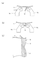
図5(a)に示すように、既にシールされた縦シール部52が片側に倒れる或いはカールすると、縦シール部52に連続し且つこれからシールされるために重ねられた包装材の側縁部51が上記の倒れやカールの影響を受け、2度のシール打ちの際に縦シール部50,52が綺麗に連続しないことがある。即ち、図5(b)に示すように、倒れた縦シール部52を縦ヒートシーラ部15a,15bが不規則に挟み込む等の不具合が生じる。また、図5(c)に示すように、縦のシール筋目53が連続しなくなり、見栄えが悪くなる。こうした縦シール部の不規則な挟み込みは、不完全な縦シール部の原因になり得ると共に、製造された袋包装体の美観を損ね、好ましくない。
As shown in FIG. 5 (a), when the already sealed
そこで、間欠的に走行する包装材の両側縁部が縦ヒートシーラで合掌状にヒートシールされて筒状包装材に形成される製袋包装機において、筒状包装材に形成の際に、既に形成された縦シール部の倒れが生じようとしても、その影響が縦ヒートシーラ内の縦シール部や側縁部に及ぶまで大きくなるのを防止する点で解決すべき課題がある。 Therefore, in the bag-making packaging machine in which both side edges of the packaging material that travels intermittently are heat-sealed in the shape of a palm with a vertical heat sealer to form the cylindrical packaging material, it is already formed when forming the cylindrical packaging material Even if the vertical seal portion is tilted, there is a problem to be solved in terms of preventing the influence from increasing to the vertical seal portion and the side edge portion in the vertical heat sealer.
この発明の目的は、間欠作動中の停止のみならず、何らかの都合で製袋包装機を一旦停止した結果、縦シール部の冷却時間が長く続くような場合であっても、上記のような縦シール部の倒れに起因した不良な縦ヒート部の発生を未然に回避して、ヒートシールが綺麗で、袋又は袋包装体の仕上がりが良好な製袋包装機を提供することである。 The object of the present invention is not only to stop the intermittent seal operation, but also to prevent the bag making and packaging machine from being temporarily stopped for some reason. An object of the present invention is to provide a bag making and packaging machine that avoids the occurrence of a defective vertical heat portion due to the collapse of the seal portion, has a beautiful heat seal, and has a good bag or bag package finish.
上記の課題を解決するため、この発明による製袋包装機は、間欠送りされる包装材を筒状包装材に成形するため前記包装材の走行両側の側縁部を合掌状の縦シール部にシールする縦ヒートシーラを備えており、前記縦ヒートシーラから送り出された前記縦シール部の倒れを規制する規制部材が配設されていることから成っている。 In order to solve the above-mentioned problems, a bag making and packaging machine according to the present invention forms a packaging material that is intermittently fed into a cylindrical packaging material. A vertical heat sealer for sealing is provided, and a restriction member for restricting the fall of the vertical seal portion fed from the vertical heat sealer is provided.
この製袋包装機によれば、縦ヒートシーラによって形成された縦シール部が縦ヒートシーラから送り出されたときに、その縦シール部の倒れを防止する規制部材が設けられており、規制部材は縦ヒートシーラから送り出されたシール済の縦シール部の倒れを防止している。規制部材は、縦シール部の連続性のために縦ヒートシーラ内において一部が残されているシール済の縦シール部及びそれに続く未シール部としての側縁部の状態にも影響を及ぼし、曲成された包装材からの起立状態を維持している。したがって、包装機の間欠的な動作に伴って縦ヒートシーラが間欠的に閉じ動作するときに、縦ヒートシーラ内部に位置している縦シール部及び側縁部は起立状態にあって縦ヒートシーラによって正しく挟み込まれる。その結果、開いた縦ヒートシーラ内に位置している縦シール部及び側縁部が、倒れた状態で縦ヒートシールされることが防止され、既に形成されている縦シール部と綺麗に繋がった連続性のある縦シール部が形成される。 According to this bag making and packaging machine, when the vertical seal portion formed by the vertical heat sealer is sent out from the vertical heat sealer, the restriction member is provided to prevent the vertical seal portion from falling, and the restriction member is the vertical heat sealer. This prevents the vertical seal part that has been sent out from falling down. The restricting member also affects the state of the sealed vertical seal part that is partially left in the vertical heat sealer due to the continuity of the vertical seal part and the side edge part as the subsequent unsealed part. The upright state from the formed packaging material is maintained. Therefore, when the vertical heat sealer intermittently closes with the intermittent operation of the packaging machine, the vertical seal part and the side edge located inside the vertical heat sealer are in an upright state and are correctly sandwiched by the vertical heat sealer. It is. As a result, the vertical seal part and the side edge part located in the open vertical heat sealer are prevented from being vertically heat sealed in a collapsed state, and are continuously connected to the already formed vertical seal part. A vertical seal portion having a characteristic is formed.
この製袋包装機において、前記規制部材は、前記縦ヒートシーラの前記縦シール部が送り出される側の端部に直近して連結されている。規制部材をこのように配設することにより、規制部材は、縦シール部の連続性のために縦ヒートシーラ内において一部が残されている縦シール部及びそれに続く未シール部としての側縁部の状態に最も効果的に影響を及ぼし、曲成された包装材からの起立状態を維持することができる。 In this form-fill-seal machine, said regulating member, that is connected with the nearest to the end of the side where vertical seal portion is fed out of the longitudinal heat sealer. By arranging the restricting member in this way, the restricting member has a longitudinal seal portion that is partially left in the longitudinal heat sealer for the continuity of the longitudinal seal portion, and a side edge portion as a subsequent unsealed portion. Can be most effectively affected, and can maintain the standing state from the bent packaging material.
この製袋包装機において、前記縦ヒートシーラは固定側縦ヒートシーラ部と当該固定側縦ヒートシーラ部に対して接離可能な可動側縦ヒートシーラ部とを備えており、前記規制部材は前記固定側縦ヒートシーラ部に連結されている。固定側縦ヒートシーラ部は、可動側縦ヒートシーラ部と異なり、製袋包装機の作動中に位置を変えないので、規制部材を固定側縦ヒートシーラ部に配置することによって、製袋包装機の運転中において規制部材を縦シール部及びそれに続く未シール部としての側縁部に対して一定の相対位置に置くことができる。 In this bag-making packaging machine, the vertical heat sealer includes a fixed-side vertical heat sealer portion and a movable-side vertical heat sealer portion that can be moved toward and away from the fixed-side vertical heat sealer portion, and the regulating member is the fixed-side vertical heat sealer. that it has been linked to the part. Unlike the movable side vertical heat sealer, the fixed side vertical heat sealer does not change its position during the operation of the bag making and packaging machine, so the restriction member is placed in the fixed side vertical heat sealer during operation of the bag making and packaging machine. The regulating member can be placed at a certain relative position with respect to the longitudinal seal portion and the side edge portion as the subsequent unsealed portion.
この製袋包装機において、前記規制部材は、前記縦シール部の各側方にそれぞれに対向配置された規制片と、前記規制片を開閉可能に作動させるアクチュエータ部とを備えている。規制片を縦シール部の各側方にそれぞれに対向配置させることで、縦シール部の倒れようとする方向がいずれであっても、規制部材において部品等の何らの交換も要することなく、その倒れを規制することができる。また、規制片を開閉可能に作動させるアクチュエータ部を備えることにより、規制片を縦シール部から遠く後退させた開き位置と、開き位置よりは閉じていて縦シール部に接近させた接近位置との間で開閉させることができる。規制片は、接近位置では、完全に閉じて縦シール部を挟み込む状態ではなく、ある程度開いていて縦シール部の通過を許容する。 In this form-fill-seal machine, said regulating member has a regulating piece that is opposed to the respective side of the longitudinal seal portion, Ru Tei and an actuator portion for openably operating the regulating piece. By arranging the regulating pieces on the respective sides of the vertical seal portion so as to face each other, it is possible to replace the parts in the regulating member without any replacement in any direction in which the vertical seal portion is about to fall down. Can fall down. In addition, by providing an actuator unit that actuates the regulating piece so that it can be opened and closed, an opening position in which the regulating piece is retracted far from the vertical seal part and an approach position in which the regulating piece is closed rather than the open position and approached the vertical seal part Can be opened and closed between. In the approach position, the regulating piece is not completely closed and sandwiches the vertical seal portion, but is open to some extent to allow passage of the vertical seal portion.
この製袋包装機において、前記両規制片は、前記規制部材の前記製袋包装機へのセットの際、及び前記製袋包装機からセット解除の際に、前記アクチュエータ部によって開状態とされる。規制部材を製袋包装機へセットする際、及び製袋包装機からセット解除する際に、両規制片の開閉程度を変更することができる。即ち、両規制片は、運転開始に先立っての規制部材の製袋包装機へのセットに際してはアクチュエータ部によって開状態とされ、規制片が、規制部材の製袋包装機へのセット時に既シール部としての縦シール部や未シール部としての重なった側縁部と干渉するのが回避される。規制部材のセットの後、アクチュエータ部の作動によって、両規制片を閉じて縦シール部や側縁部に接近した接近位置を取らせることができる。製袋包装機のメンテナンス等の場合にセット解除する際にも、予め規制片を開いた状態とするので縦シール部や側縁部と干渉しない位置とすることができる。 In this form-fill-seal machine, said both restricting pieces, when set to the bag packaging machine of the regulating member, and when the setting release from the bag packaging machine, Ru is an open state by the actuator unit . When the restriction member is set in the bag making and packaging machine and when the set is released from the bag making and packaging machine, the degree of opening and closing of both restriction pieces can be changed. That is, both restriction pieces are opened by the actuator when the restriction member is set on the bag making and packaging machine prior to the start of operation, and the restriction piece is already sealed when the restriction member is set on the bag making and packaging machine. Interference with the vertical seal part as the part and the overlapping side edge part as the non-seal part is avoided. After the setting of the restricting member, both the restricting pieces can be closed and the approaching position approaching the vertical seal portion or the side edge portion can be taken by operating the actuator portion. When unset in case of maintenance or the like of the bag making and packaging machine can also be a position that does not interfere with the vertical seal portion and the side edge portion so that an open state in advance restricting piece.
この製袋包装機において、前記規制部材を支持し且つ前記製袋包装機の正面に対して左端又は右端に設けられた縦軸の回りに回動して開閉する扉状の第1フレームと、前記第1フレームを前記製袋包装機の正面に対して進退自在に支持する第2フレームとを更に備えることができる。このような第1及び第2のフレームを備えることにより、規制部材及び縦ヒートシーラのセット解除に際しては、第2フレームを作動させて、第1フレームの全体を製袋包装機の正面に対して後退させ、その状態で第1フレームを回動させて、製袋包装機の正面を開くことができる。また、規制部材及び縦ヒートシーラのセットに際しては、第1フレームを回動させて製袋包装機の正面に据え、その状態で第2フレームを作動させて第1フレームの全体をそのまま製袋包装機の正面に前進させてセットする。このような回動動作と進退動作とを第1及び第2のフレームに分担させて組み合わせることにより、規制部材及び縦ヒートシーラを回動動作で直接セットするときに、縦シール部や側縁部と干渉するのを防止することができる。 In this bag making and packaging machine, a door-shaped first frame that supports the regulating member and rotates around a vertical axis provided at the left end or the right end with respect to the front of the bag making and packaging machine, and opens and closes; And a second frame that supports the first frame so as to be movable forward and backward with respect to the front surface of the bag making and packaging machine. By providing such first and second frames, when releasing the set of the regulating member and the vertical heat sealer, the second frame is operated to retract the entire first frame from the front of the bag making and packaging machine. In this state, the front of the bag making and packaging machine can be opened by rotating the first frame. Further, when setting the regulating member and the vertical heat sealer, the first frame is rotated and placed on the front surface of the bag making and packaging machine, and the second frame is operated in that state, and the entire first frame is left as it is. Set it forward in front of. By combining the pivoting operation and the advancing / retreating operation with the first and second frames in combination, when the regulating member and the longitudinal heat sealer are directly set by the pivoting operation, the longitudinal seal portion and the side edge portion Interference can be prevented.
この製袋包装機において、前記両規制片は、少なくとも前記包装材の送り開始時からその後の前記縦ヒートシーラの作動開始時までに渡って、前記アクチュエータ部によって前記縦シール部に接近した接近位置に作動させることができる。これにより、製袋包装機の運転において、少なくとも、包装材の送りが開始されてその後、送りが停止され、更に縦ヒートシーラの作動が開始される時まで、規制部材の規制片は縦シール部に比較的接近して縦シール部の倒れを防止することができる。 In the bag making and packaging machine, the two restriction pieces are moved to an approach position close to the vertical seal portion by the actuator portion at least from the start of feeding of the packaging material to the subsequent start of operation of the vertical heat sealer. Can be operated. Thereby, in the operation of the bag making and packaging machine, at least when the feeding of the packaging material is started and then the feeding is stopped and the operation of the vertical heat sealer is further started, the regulating piece of the regulating member is placed on the vertical sealing portion. The vertical seal portion can be prevented from falling down relatively close.
この製袋包装機において、前記両規制片は、ワイヤ状、ロッド状又はプレート状の形態を備えたものとすることができる。規制片の形態は、ワイヤ状、ロッド状、プレート状のいずれでも可能であるが、走行の際の摩擦抵抗の小さい材料や表面形態、例えば、滑らかなテフロン(登録商標)表面を選択することが好ましい。 In the bag making and packaging machine, both the restricting pieces may have a wire shape, a rod shape, or a plate shape. The shape of the restriction piece can be any of a wire shape, a rod shape, and a plate shape, but a material or a surface shape having a low frictional resistance during traveling, for example, a smooth Teflon (registered trademark) surface can be selected. preferable.
この発明による製袋包装機は、上記のように構成されているので、間欠的に走行する包装材の両側縁部が縦ヒートシーラで合掌状にヒートシールされて筒状包装材に形成される際に、縦シール部の縦ヒートシーラによる挟み込みが解除されても、既に形成された縦シール部の倒れやカールの発生を規制部材が規制することができる。即ち、縦シール部の倒れに起因してその影響が縦ヒートシーラ内の縦シール部や側縁部に及ぶが、規制部材を設けることで、この影響を未然に防止することができる。包装機の運転中を含む縦ヒートシーラ及び規制部材が包装機にセットされている状態では、間欠作動中の停止のみならず、何らかの都合で製袋包装機を一旦停止した結果、たとえ縦シール部の冷却時間が長く続くような場合であっても、縦シール部に接近された規制部材は、縦ヒートシーラ内における縦シール部及び側縁部の起立状態とし、縦シール部の倒れに起因した縦ヒートシールの不良を未然に回避する。したがって、縦ヒートシーラがヒートシール動作を再開したときに、後続の縦シール部はシール済の縦シール部に対して綺麗に連続した縦シールとなり、袋又は袋包装体の仕上がりを良好にする。
規制部材は、縦ヒートシーラの縦シール部が送り出される側の端部に直近して連結されているので、縦ヒートシーラ内において一部が残されている縦シール部及びそれに続く未シール部としての側縁部の状態に最も効果的に影響を及ぼし、曲成された包装材からの起立状態を維持することができる。また、縦ヒートシーラは固定側縦ヒートシーラ部と当該固定側縦ヒートシーラ部に対して接離可能な可動側縦ヒートシーラ部とを備えており、規制部材は固定側縦ヒートシーラ部に連結されているので、固定側縦ヒートシーラ部は製袋包装機の作動中に位置を変えず、製袋包装機の運転中において規制部材は縦シール部及びそれに続く未シール部としての側縁部に対して一定の相対位置に置くことができる。また、規制部材に備わる規制片を縦シール部の各側方にそれぞれに対向配置させているので、縦シール部の倒れようとする方向がいずれであってもその倒れを規制することができ、また、規制部材は規制片を開閉可能に作動させるアクチュエータ部を備えることにより、規制片を縦シール部から遠く後退させた開き位置と、縦シール部に接近させるが完全には閉じずに縦シール部の通過を許容する接近位置との間で開閉させることができ、更に、規制部材の製袋包装機へのセットの際、及び製袋包装機からセット解除の際に、アクチュエータ部によって規制片を開状態としているので、規制部材のセット時に既シール部としての縦シール部や未シール部としての重なった側縁部と干渉することがなく、また、包装機の運転中止中で、縦ヒートシーラ及び規制部材を製袋包装機へのセット状態から解除する場合には、規制部材を開くとともに製袋包装機から手前側に後退させ、その後、縦ヒートシーラを左右に開くなどすることにより、規制部材を縦シール部や側縁部と干渉しない位置に後退させた上で、縦ヒートシーラを製袋包装機へのセット状態から解除することができる。
Since the bag making and packaging machine according to the present invention is configured as described above, when both side edges of the packaging material traveling intermittently are heat-sealed in a palm shape with a vertical heat sealer, it is formed into a cylindrical packaging material. In addition, even when the vertical heat sealer sandwiches the vertical seal part, the regulating member can regulate the fall of the already formed vertical seal part and the occurrence of curling. That is, due to the fall of the vertical seal portion, the influence extends to the vertical seal portion and the side edge portion in the vertical heat sealer, but this influence can be prevented beforehand by providing a regulating member. In the state where the vertical heat sealer and the regulating member are set in the packaging machine including during the operation of the packaging machine, not only the intermittent operation is stopped, but also the bag making packaging machine is temporarily stopped for some reason. Even if the cooling time continues for a long time, the regulating member approaching the vertical seal part is in the standing state of the vertical seal part and the side edge part in the vertical heat sealer, and the vertical heat caused by the fall of the vertical seal part Avoid bad seals in advance. Therefore, when the vertical heat sealer resumes the heat sealing operation, the subsequent vertical seal portion becomes a clean continuous vertical seal with respect to the sealed vertical seal portion, and the finish of the bag or bag package is improved.
Since the regulating member is connected in close proximity to the end of the vertical heat sealer on the side where the vertical seal portion is sent out, the vertical seal portion that is partially left in the vertical heat sealer and the side as the unsealed portion that follows it It most effectively affects the state of the edge and can maintain the standing state from the bent packaging material. Further, the vertical heat sealer includes a fixed side vertical heat sealer part and a movable side vertical heat sealer part that can be moved toward and away from the fixed side vertical heat sealer part, and the regulating member is connected to the fixed side vertical heat sealer part. The fixed-side vertical heat sealer does not change its position during the operation of the bag making and packaging machine, and during operation of the bag making and packaging machine, the regulating member is fixed relative to the vertical seal part and the subsequent side edge as an unsealed part. Can be put in position. In addition, since the restriction pieces provided in the restriction member are arranged to face each side of the vertical seal part, the fall of the vertical seal part can be restricted regardless of the direction in which it is about to fall down. In addition, the regulating member is provided with an actuator portion that operates to open and close the regulating piece, so that the regulating piece is retracted far from the vertical sealing portion, and the vertical sealing portion is brought into close contact with the vertical sealing portion but not completely closed. It can be opened and closed with an approaching position that allows passage of the part, and further, when the restriction member is set on the bag making and packaging machine and when the set is released from the bag making and packaging machine, the since the open state, not interfere with the overlapping side edges of the vertical seal portion and the unsealed portion of the already sealed portion when the set of the regulating member, also in a stop operation of the packaging machine, the vertical heat When released over La and regulating member from the set state to the bagging and packaging machine is retracted to the front side from the bag making and packaging machine along with opening the regulating member, then open the vertical heat sealer to the left and right by like, The vertical heat sealer can be released from the set state in the bag making and packaging machine after the regulating member is retracted to a position where it does not interfere with the vertical seal portion or the side edge portion .
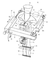
以下、添付した図面に基づいて、この発明による製袋包装機の実施形態を説明する。図1は、この発明による製袋包装機を具体化した縦型製袋充填包装機の斜視図である。縦型製袋充填包装機(以下、「製袋充填包装機」という)10は、公知の構造であるが、ウェブ状包装材が巻き取られている包装材ロールから繰り出されるウェブ状包装材Fwは幾つかのガイドローラや張力付与機構(図示しない)を経て、製袋充填包装機10のフォーマ11に供給される。供給途上のウェブ状包装材には、必要な印字が施される。また、包装材上のマークがセンサで読み取られており、袋の形成及び袋内部への製品の充填とのタイミングを計って、包装材がフォーマ11に供給される。製袋充填包装機10は、更に、筒状に曲成された包装材Fwをその両側端縁51,51に縦シールを施して筒状包装材Ftに成形する縦シール手段としての縦ヒートシーラ15、サーボモータによって駆動され筒状包装材Ftの縦シール部を含む横断領域を挟み込んで横シールを施して袋を形成する横シール手段としての横ヒートシーラ16,16を備えている。
Hereinafter, an embodiment of a bag making and packaging machine according to the present invention will be described with reference to the accompanying drawings. FIG. 1 is a perspective view of a vertical bag making and filling machine embodying a bag making and packaging machine according to the present invention. The vertical bag making and filling machine (hereinafter referred to as “bag making and filling machine”) 10 has a known structure, but the web-like packaging material Fw fed out from the packaging material roll around which the web-like packaging material is wound. Is supplied to the former 11 of the bag making filling and
製袋充填包装機10においては、フォーマ11内に製品を投入案内するための投入筒12が貫通配置されており、投入筒12の上部は断面が拡大したホッパ13とされている。フォーマ11によってその内部に筒状に曲成された包装材は、投入筒12の周囲を取り巻くように案内され、同期して作動する包装材送り用の左右一対のベルト送り機構14,14(一方側のみ示す)によって、下方へ間欠的に紙送りされる。筒状に曲成された包装材は、投入筒12の周囲を下方に走行される間の間欠動作の停止中に縦ヒートシーラ15によって、側端縁51,51同士が熱溶着されて、筒状包装材Ftに成形される。縦ヒートシーラ15は、側端縁51,51同士を挟み込んでヒートシールを施すバー状の二つのヒートシーラ部15a,15bを備え、側端縁51,51に合掌貼りを施す。各ヒートシーラ部は、公知であるが、先端側にヒートパイプを、また中央部分にカートリッジヒータを備えている。
In the bag making and filling and
筒状包装材Ftは、投入筒12の下端から下方へ送り出される。製品が投入・充填された筒状包装材は、横ヒートシーラ16,16によって、袋の天シール部と次の袋の底シール部Sとが形成される。包装材は間欠ながら順次供給されて、製品を包装した袋包装体Pが順次製造される。
The cylindrical packaging material Ft is sent downward from the lower end of the
図1を参照すると、製袋充填包装機10は、包装材を筒状包装材に成形する縦ヒートシーラ15から送り出された縦シール部52が間欠送りに伴って縦ヒートシーラ15から送り出されたときに、縦シール部52の倒れを規制する規制部材20を備えている。
Referring to FIG. 1, the bag making filling and
図2は、この発明に用いられる規制部材の一例を示す平面図である。規制部材20は、ロボットや工作機械等の技術分野で、対象物を把持する把持手段として市場で入手可能なものである。規制部材20は、縦シール部の各側方にそれぞれに対向配置された規制片21,21と、規制片21,21を開閉可能に作動させるアクチュエータ部22とを備えている。アクチュエータ部22は、エアの供給を受けて作動するアクチュエータである。アクチュエータの型式として、開閉動作の一方のみをエアシリンダで行う単動型、又は開閉動作の両方をエアシリンダで行う複動型があり、単動型の場合には反対側の動作を行わせるため、ばねと組み合わせることができる。把持手段の場合、エアシリンダの作動をフィンガ23,23の回動動作に変換することで、フィンガ23,23間に対象物を把持又は把持解除を行う。
FIG. 2 is a plan view showing an example of a regulating member used in the present invention. The restricting
図3は、この発明による製袋充填包装機10の要部を示す図であって、(a)は正面図、(b)は横断面図である。上記把持手段が縦シール部52の倒れの規制に用いられる規制部材20として適用されるときは、フィンガ23,23にそれぞれ規制片21,21が取り付けられる。各規制片21は、縦シール部52の各側方にそれぞれに対向配置される。アクチュエータ部22の作動によってフィンガ23,23を介して規制片21,21を開閉可能に作動させることで、規制片21,21を縦シール部52から遠く後退させた開き位置と、開き位置よりは閉じていて縦シール部52に接近させた接近位置との間で開閉させることができる。規制部材20は、規制片21,21が接近位置を占めるときに縦シール部52に接近するけれども完全に閉じることはなく、隙間Gだけ開いている。規制片21,21は、接近位置では、縦シール部52がいずれの方向に倒れようとしても、またカールを生じようとしても、規制片21,21が縦シール部52をその幅内に規制することで、そうした現象を防止することができる。したがって、製袋充填包装機10の間欠的な動作に伴って、包装材が送られるときには縦シール部52が規制片21,21間の隙間Gを通過可能である。また、縦ヒートシーラ15が間欠的に閉じ動作するときに、縦ヒートシーラ15内部に位置している縦シール部52及び側縁部51,51は起立状態にあって縦ヒートシーラ15によって正しく挟み込まれる。その結果、縦シール部52及び側縁部51,51が倒れた状態のままで縦ヒートシールされることが防止され、既に形成されている縦シール部52と綺麗に繋がった連続性のある縦シール部が形成される。
FIGS. 3A and 3B are diagrams showing a main part of the bag making and filling and
各規制片21は、図示のものではプレート状の形態とされているが、ワイヤ状のものを曲げ加工したもの、ロッド状のものとすることができる。また、材料としては、走行の際に摩擦抵抗の小さい材料や表面形態、例えば、滑らかなテフロン(登録商標)表面を選択することが好ましい。
Each of the restricting
規制部材20は、この例では、縦ヒートシーラ15の縦シール部52が送り出される下側端部15cに直近位置に連結されている。具体的には、規制部材20は、縦ヒートシーラ15の固定側縦ヒートシーラ部15aの下側端部に機械的に連結されていて、製袋充填包装機の作動中に位置を変えない。このように配置された規制部材20は、縦ヒートシーラ15内において一部が残されている縦シール部52及びそれに続く未シール部としての側縁部51,51が倒れを生じようとしても、一定の位置から最も効果的に影響を及ぼし、曲成された包装材Ftからの起立状態を維持する。
In this example, the regulating
製袋充填包装機10をメンテナンス等のために、縦ヒートシーラ15を左側又は右側に設けられた縦軸の回りに開いて製袋充填包装機10の正面から移動させる場合がある。このとき規制部材20も縦ヒートシーラ15とともに移動される。規制部材20の両規制片21,21を閉じた状態で縦軸の回りに開くと、閉じた両規制片21,21をメンテナンス終了後に縦軸の回りに閉じて再セットするときには、規制片21が縦シール部52(倒れる又はカールしている可能性が高い)に干渉するおそれがある。同様に、縦ヒートシーラ15及びそれに関連する部品も縦シール部52に干渉するおそれがある。こうした干渉は、縦シール部52を変形させる等の不都合な影響を及ぼす。
In some cases, the
そこで、規制部材20については、製袋充填包装機10へのセットの際、及びセット解除の際には、両規制片21,21をアクチュエータ部22によって予め開き状態にしておくことが好ましい。このようにすることで、規制部材20の製袋充填包装機10へのセットの際、及びセット解除の際に、両規制片21,21が縦シール部52や未シール部としての重なった側縁部51,51に干渉するのを防止することができる。規制部材20のセットの後、アクチュエータ部22の作動によって両規制片21,21を閉じて縦シール部52や側縁部51,51に接近した接近位置を取らせることができる。製袋充填包装機10のメンテナンス等の場合にセット解除する際にも、予め規制片21,21を開いた状態として縦シール部52や側縁部51,51と干渉しない位置とすることが好ましい。
Therefore, the restricting
規制部材20について製袋充填包装機10へのセットの際、及びセット解除の際に、縦シール部52や未シール部としての重なった側縁部51,51との干渉を更に回避するために、規制部材20及び縦ヒートシーラ15を、製袋充填包装機10の正面に対して進退可能とする動作と、左側又は右側に開く回動動作とを組み合わせることが好ましい。
In order to further avoid interference with the
即ち、図1に示されているように、規制部材20を支持し且つ製袋充填包装機10の正面に対して左端又は右端に設けられた縦軸30の回りに回動して開閉する第1フレーム31と、第1フレーム31を製袋充填包装機1の正面に対して進退自在に支持する第2フレーム32とを備えている。第1フレーム31は右側の縦軸30の回りに回動可能であり、第1フレーム31を左側の第2フレーム32aに対してロック又はロック解除させる操作のために、第1フレーム31にはハンドル33が設けられている。第1フレーム31には、縦ヒートシーラ15と規制部材20とが取り付けられている。
That is, as shown in FIG. 1, the regulating
一方、第2フレーム32は、左側の第2フレーム32aとともに右側の第2フレーム32bを有している。第2フレーム32a,32bには、それぞれ、製袋充填包装機10の背面に設けられたモータ34によって駆動されるねじ伝動機構35,35が備わっており、同期して作動することにより、前後方向に約30mm程度平行移動可能である。なお、縦シール部52の幅は約15mm程度である。
On the other hand, the
第1フレーム31及び第2フレーム32を備えることにより、規制部材20及び縦ヒートシーラ15のセット解除に際しては、先ず第2フレーム32を作動させて、第1フレーム31の全体を製袋充填包装機10の正面に対して手前側に後退させる。第2フレーム32の動作によって、規制部材20(この際には、規制片21,21は開かれている)は、縦シール部52との干渉を防ぎながら縦シール部52から後退する。その状態で第1フレーム31を縦軸30の回りに回動させることで、規制部材20及び縦ヒートシーラ15を含んだ第1フレーム31を製袋充填包装機10の正面を開くことができる。また逆に、規制部材20及び縦ヒートシーラ15を製袋充填包装機10にセットするに際しては、第1フレーム31を回動させて製袋充填包装機10の正面に据え、その状態で第2フレーム32を作動させて第1フレーム31の全体をそのまま製袋充填包装機10の正面に対して前進させてセットする。このような回動動作と進退動作とを第1フレーム31及び第2フレーム32に分担させて組み合わせることにより、規制部材20及び縦ヒートシーラ15を縦軸30に回りにおける回動動作のみで直接セットするときに生じやすい縦シール部52や側縁部51,51との干渉を、未然に防止することができる。
By providing the
この製袋包装機において、両規制片21,21は、少なくとも包装材の送り開始時からその後の縦ヒートシーラ15の作動開始時までに渡って、アクチュエータ部22によって縦シール部52に接近した接近位置に作動させることができる。これにより、製袋充填包装機10の運転において、少なくとも、包装材の送りが開始されてその後、送りが停止され、更に縦ヒートシーラ15の作動が開始される時まで、規制部材20の規制片21,21は縦シール部52に比較的接近して縦シール部52の倒れを防止することができる。
In this bag making and packaging machine, the two restricting
10 製袋充填包装機 11 フォーマ
12 投入筒 13 ホッパ
14 ベルト送り機構 15 縦ヒートシーラ
15a 固定側ヒートシールバー 15b 可動側ヒートシールバー
15c 下側端部 16 横ヒートシーラ
20 規制部材 21 規制片
22 アクチュエータ部 23 フィンガ
30 縦軸 31 第1フレーム
32(32a,32b) 第2フレーム
33 ハンドル 34 モータ
35 ねじ伝動機構
50,52 縦シール部 51,51 側端縁
Fw ウェブ状包装材 Ft 筒状包装材
G 隙間
DESCRIPTION OF
Claims (4)
前記縦ヒートシーラは、固定側縦ヒートシーラ部と当該固定側縦ヒートシーラ部に対して接離可能な可動側縦ヒートシーラ部とを備えており、
前記縦ヒートシーラから送り出された前記縦シール部の倒れを規制する規制部材が、前記縦ヒートシーラの前記縦シール部が送り出される側の端部に直近し且つ前記固定側縦ヒートシーラ部に連結されて配設されており、
前記規制部材は、前記縦シール部の各側方にそれぞれに対向配置された規制片と、前記規制片を開閉可能に作動させるアクチュエータ部とを備えており、
前記両規制片は、前記規制部材の前記製袋包装機へのセットの際、及び前記製袋包装機からセット解除の際に、前記アクチュエータ部によって開状態とされる
ことから成る製袋包装機。 In a bag making and packaging machine equipped with a vertical heat sealer that seals the side edges on both sides of the packaging material to the vertical seal part in the shape of a palm in order to form intermittently fed packaging material into a cylindrical packaging material,
The vertical heat sealer includes a fixed-side vertical heat sealer and a movable-side vertical heat sealer that is movable toward and away from the fixed-side vertical heat sealer.
A regulating member that regulates the fall of the vertical seal portion sent out from the vertical heat sealer is disposed close to the end of the vertical heat sealer on the side where the vertical seal portion is sent out and connected to the fixed side vertical heat sealer portion. Has been established,
The restricting member includes a restricting piece disposed opposite to each side of the vertical seal part, and an actuator part that operates the restricting piece so as to be openable and closable.
The both restricting pieces are opened by the actuator portion when the restricting member is set in the bag making and packaging machine and when the set is released from the bag making and packaging machine. Bag making and packaging machine.
Priority Applications (1)
| Application Number | Priority Date | Filing Date | Title |
|---|---|---|---|
| JP2006194966A JP4933180B2 (en) | 2006-07-14 | 2006-07-14 | Bag making and packaging machine |
Applications Claiming Priority (1)
| Application Number | Priority Date | Filing Date | Title |
|---|---|---|---|
| JP2006194966A JP4933180B2 (en) | 2006-07-14 | 2006-07-14 | Bag making and packaging machine |
Publications (2)
| Publication Number | Publication Date |
|---|---|
| JP2008018997A JP2008018997A (en) | 2008-01-31 |
| JP4933180B2 true JP4933180B2 (en) | 2012-05-16 |
Family
ID=39075271
Family Applications (1)
| Application Number | Title | Priority Date | Filing Date |
|---|---|---|---|
| JP2006194966A Active JP4933180B2 (en) | 2006-07-14 | 2006-07-14 | Bag making and packaging machine |
Country Status (1)
| Country | Link |
|---|---|
| JP (1) | JP4933180B2 (en) |
Families Citing this family (2)
| Publication number | Priority date | Publication date | Assignee | Title |
|---|---|---|---|---|
| JP6279369B2 (en) * | 2014-03-19 | 2018-02-14 | 株式会社イシダ | Bag making and packaging machine |
| JP6742625B2 (en) | 2016-04-28 | 2020-08-19 | 株式会社イシダ | Packaging equipment |
Family Cites Families (7)
| Publication number | Priority date | Publication date | Assignee | Title |
|---|---|---|---|---|
| JP2548399B2 (en) * | 1989-10-13 | 1996-10-30 | 松下電器産業株式会社 | Burner |
| JP3468558B2 (en) * | 1993-10-15 | 2003-11-17 | 株式会社川島製作所 | Vertical four-sided seal bag filling and packaging machine |
| JP2003116479A (en) * | 2001-10-16 | 2003-04-22 | Omori Mach Co Ltd | Transverse pillow packaging apparatus for konnyaku |
| JP2004099174A (en) * | 2002-08-23 | 2004-04-02 | Sanko Kikai Kk | Automatic packaging machine |
| JP4373701B2 (en) * | 2003-05-02 | 2009-11-25 | 株式会社川島製作所 | Gusset packaging machine |
| JP2005231722A (en) * | 2004-02-23 | 2005-09-02 | Fuji Mach Co Ltd | Bag former in vertical bag-making/filling machine |
| JP4644048B2 (en) * | 2005-06-17 | 2011-03-02 | 株式会社東京自働機械製作所 | Vertical bag making and filling machine |
-
2006
- 2006-07-14 JP JP2006194966A patent/JP4933180B2/en active Active
Also Published As
| Publication number | Publication date |
|---|---|
| JP2008018997A (en) | 2008-01-31 |
Similar Documents
| Publication | Publication Date | Title |
|---|---|---|
| US6363692B2 (en) | Method and apparatus for placing a product in a flexible recloseable container | |
| US4676051A (en) | Method and apparatus for forming, filling and sealing bags made from a continuous plastic sheet | |
| JP4773747B2 (en) | Pillow packaging machine | |
| WO2009154175A1 (en) | Bag-making packaging machine | |
| JP5955542B2 (en) | Horizontal bag making and packing machine | |
| JP4933180B2 (en) | Bag making and packaging machine | |
| JP4875877B2 (en) | Bag-making device with hem | |
| JP5941652B2 (en) | Ear folding device for pillow package in horizontal bag making and filling machine | |
| JP6109594B2 (en) | Horizontal wrapping machine with bag folding device | |
| JP2002019737A (en) | Heat-sealing device | |
| JP6255178B2 (en) | Packaging machine | |
| JP4463060B2 (en) | Vertical bag making filling and packaging machine for square bottom bags | |
| JP6521605B2 (en) | Corner seal device and packaging machine | |
| JP2007022629A (en) | Bag closing device | |
| JP6914621B2 (en) | Filling and packaging machine and filling and packaging method | |
| JP6407823B2 (en) | Vertical bag making filling and packaging machine for square bottom bags | |
| JP5995303B2 (en) | Bag making filling and packaging machine | |
| JP7012300B2 (en) | Heater bar device for packaging machine | |
| US20080163589A1 (en) | Combined packaging machine | |
| JP4132940B2 (en) | Gusset packaging machine | |
| JP3969783B2 (en) | Bag making filling and packaging machine | |
| JP5941651B2 (en) | Horizontal bag making and packaging machine and its end seal control device | |
| JP7061313B2 (en) | Packaging bag and packaging machine | |
| JP6706565B2 (en) | Wrapping machine and method of folding a package | |
| JP4549684B2 (en) | Vertical seal device in multi-row stick type automatic filling and packaging machine |
Legal Events
| Date | Code | Title | Description |
|---|---|---|---|
| A621 | Written request for application examination |
Free format text: JAPANESE INTERMEDIATE CODE: A621 Effective date: 20090710 |
|
| A977 | Report on retrieval |
Free format text: JAPANESE INTERMEDIATE CODE: A971007 Effective date: 20111028 |
|
| A131 | Notification of reasons for refusal |
Free format text: JAPANESE INTERMEDIATE CODE: A131 Effective date: 20111115 |
|
| A521 | Request for written amendment filed |
Free format text: JAPANESE INTERMEDIATE CODE: A523 Effective date: 20120114 |
|
| TRDD | Decision of grant or rejection written | ||
| A01 | Written decision to grant a patent or to grant a registration (utility model) |
Free format text: JAPANESE INTERMEDIATE CODE: A01 Effective date: 20120207 |
|
| A01 | Written decision to grant a patent or to grant a registration (utility model) |
Free format text: JAPANESE INTERMEDIATE CODE: A01 |
|
| A61 | First payment of annual fees (during grant procedure) |
Free format text: JAPANESE INTERMEDIATE CODE: A61 Effective date: 20120216 |
|
| R150 | Certificate of patent or registration of utility model |
Ref document number: 4933180 Country of ref document: JP Free format text: JAPANESE INTERMEDIATE CODE: R150 Free format text: JAPANESE INTERMEDIATE CODE: R150 |
|
| FPAY | Renewal fee payment (event date is renewal date of database) |
Free format text: PAYMENT UNTIL: 20150224 Year of fee payment: 3 |
|
| R250 | Receipt of annual fees |
Free format text: JAPANESE INTERMEDIATE CODE: R250 |
|
| R250 | Receipt of annual fees |
Free format text: JAPANESE INTERMEDIATE CODE: R250 |
|
| R250 | Receipt of annual fees |
Free format text: JAPANESE INTERMEDIATE CODE: R250 |
|
| R250 | Receipt of annual fees |
Free format text: JAPANESE INTERMEDIATE CODE: R250 |
|
| R250 | Receipt of annual fees |
Free format text: JAPANESE INTERMEDIATE CODE: R250 |
|
| R250 | Receipt of annual fees |
Free format text: JAPANESE INTERMEDIATE CODE: R250 |