JP4930622B2 - Inkjet printer and printing method - Google Patents
Inkjet printer and printing method Download PDFInfo
- Publication number
- JP4930622B2 JP4930622B2 JP2010094759A JP2010094759A JP4930622B2 JP 4930622 B2 JP4930622 B2 JP 4930622B2 JP 2010094759 A JP2010094759 A JP 2010094759A JP 2010094759 A JP2010094759 A JP 2010094759A JP 4930622 B2 JP4930622 B2 JP 4930622B2
- Authority
- JP
- Japan
- Prior art keywords
- data
- print data
- pulse
- shift register
- Prior art date
- Legal status (The legal status is an assumption and is not a legal conclusion. Google has not performed a legal analysis and makes no representation as to the accuracy of the status listed.)
- Expired - Lifetime
Links
Images


Description
本発明は、同一のノズルから異なる大きさのインク滴を吐出することができるインクジェット式プリンタに関し、特に、一印刷周期中に複数のインク滴を吐出可能なインクジェット式プリンタに関する。 The present invention relates to an ink jet printer that can eject ink droplets of different sizes from the same nozzle, and more particularly to an ink jet printer that can eject a plurality of ink droplets during one printing cycle.
従来より、コンピュータの出力装置として、数色のインクをプリントヘッドから吐出するタイプのカラーインクジェット式プリンタが普及し、コンピュータ等が処理した画像を多色多階調で印刷するのに広く用いられている。 2. Description of the Related Art Conventionally, color ink jet printers that eject several colors of ink from a print head have become widespread as computer output devices, and are widely used for printing images processed by computers and the like in multiple colors and multiple gradations. Yes.
インクジェット式プリンタは、副走査方向(紙送り方向)に多数のノズルを備えたプリントヘッドを有しており、このプリントヘッドをキャリッジ機構によって主走査方向に移動させ、上記副走査方向に所定の紙送りを行うことで、所望の印刷結果を得るものである。ホストコンピュータから入力された印刷データを展開してなるドットパターンデータに基づいて、プリントヘッドの各ノズルからインク滴がそれぞれ所定のタイミングで吐出され、これらの各インク滴が記録紙等の印刷記録媒体に着弾し付着することにより、印刷が行われる。このようにインクジェット式プリンタは、インク滴を吐出するかしないか、つまりドットのオンオフ制御を行うものであるため、このままでは灰色等の中間階調を印刷出力することができない。 The ink jet printer has a print head having a large number of nozzles in the sub-scanning direction (paper feeding direction). The print head is moved in the main scanning direction by a carriage mechanism, and a predetermined paper in the sub-scanning direction is moved. By performing the feeding, a desired print result is obtained. Based on dot pattern data obtained by developing print data input from the host computer, ink droplets are ejected from the nozzles of the print head at predetermined timings, and these ink droplets are printed on a recording medium such as recording paper. Printing is performed by landing on and adhering to the surface. As described above, the ink jet printer does not eject ink droplets, that is, performs dot on / off control. Therefore, it is not possible to print out an intermediate gradation such as gray.
そこで、従来より、同一ノズルからインク重量の異なる複数のインク滴を吐出することで記録ドット径を可変に制御できるようにしたインクジェット式プリンタが用いられている。例えば、特開平10−81013号公報等に記載されているインクジェット式プリンタでは、一印刷周期毎に出力される駆動信号を複数の駆動パルスから構成し、各駆動パルスにそれぞれ対応したパルス選択信号を含んでなる印刷データによって各駆動パルスのうちいずれか一つ又は複数の駆動パルスを選択するようにしている。即ち、上記特開平10−81013号公報等記載の従来例では、例えば、一印刷周期毎に出力される駆動信号を、第1パルス(中ドット)、第2パルス(小ドット)、第3パルス(中ドット)、第4パルス(微振動)から成る4つの駆動パルスから構成し、各駆動パルス毎に1ビットのデータを割り当てて印字データを構成する。そして、無ドットの階調値1の場合は、スイッチ回路に対して、第1〜第3パルスの発生期間中は「0」を印加する一方、第4パルスの発生と同期させて「1」を印加することにより、微振動を発生させる第4パルスのみを圧電振動子に供給することで、インク滴を吐出しない無ドットの階調値1を実現する。このため、階調値1を示す2ビットのデータ(00)をデコーダによって4ビットのデータ(0001)に翻訳(デコード)した上で、上述したスイッチ回路に印加する。
Therefore, conventionally, an ink jet printer has been used in which a recording dot diameter can be variably controlled by ejecting a plurality of ink droplets having different ink weights from the same nozzle. For example, in an ink jet printer described in Japanese Patent Application Laid-Open No. 10-81013 or the like, a drive signal output for each printing cycle is composed of a plurality of drive pulses, and a pulse selection signal corresponding to each drive pulse is provided. One or a plurality of drive pulses are selected from the drive pulses according to the print data included. That is, in the conventional example described in the above Japanese Patent Laid-Open No. 10-81013, for example, the drive signal output for each printing cycle is the first pulse (medium dot), the second pulse (small dot), the third pulse. It consists of four drive pulses consisting of (medium dot) and fourth pulse (fine vibration), and 1-bit data is assigned to each drive pulse to constitute print data. In the case of the dot-
同様に、小ドットの階調値2の場合は、スイッチ回路に対して、第1、第3、第4パルスの発生期間中は「0」を印加する一方、第2パルスの発生と同期させて「1」を印加すれば、第2パルスのみを圧電振動子に供給することで、小ドット相当のインク滴を吐出する階調値2を実現できる。この場合には、階調値2を示す2ビットのデータ(01)をデコーダによって4ビットのデータ(0100)に翻訳(デコード)した上で、上述したスイッチ回路に印加する。
Similarly, in the case of
同様に、1個の中ドットの階調値3の場合は、スイッチ回路に対して、第1パルスの発生と同期させて「1」を印加する一方、第2〜第4パルスの発生期間中は「0」を印加すれば、第1パルスのみを圧電振動子に供給することで、中ドット相当のインク滴を吐出する階調値3を実現できる。この場合には、階調値3を示す2ビットのデータ(10)をデコーダによって4ビットのデータ(1000)に翻訳(デコード)した上で、上述したスイッチ回路に印加する。
Similarly, in the case of
同様に、2個の中ドットで大ドットを形成する階調値4の場合は、スイッチ回路に対して、第1、第3パルスの発生と同期させて「1」を印加する一方、第2、第4パルスの発生期間中は「0」を印加すれば、第1及び第3パルスのみを圧電振動子に供給することで、中ドット相当のインク滴を2回吐出させ、これらが記録紙上に続けて着弾し、両者が混じり合って実質的に1つの大ドットを形成し得るので、階調値4を実現できる。この場合には、階調値4を示す2ビットのデータ(11)をデコーダによって4ビットのデータ(1010)に翻訳(デコード)した上で、上述したスイッチ回路に印加する。 Similarly, in the case of a gradation value of 4 in which two medium dots form a large dot, “1” is applied to the switch circuit in synchronization with the generation of the first and third pulses, while the second If “0” is applied during the generation period of the fourth pulse, only the first and third pulses are supplied to the piezoelectric vibrator, thereby ejecting ink droplets corresponding to medium dots twice, which are recorded on the recording paper. In this way, it is possible to land, and the two can be mixed to form substantially one large dot, so that a gradation value of 4 can be realized. In this case, 2-bit data (11) indicating a gradation value of 4 is translated (decoded) into 4-bit data (1010) by a decoder and applied to the above-described switch circuit.
一方、インクジェット式プリンタのプリントヘッド内に実装されたヘッド駆動回路には、各色インク滴を吐出するためのノズル列毎に対応して、複数の駆動素子に駆動信号を供給するためのスイッチ回路から成るトランスミッションゲート(TransmissionGate、以下、TGと呼ぶ)が設けられている。 On the other hand, a head drive circuit mounted in a print head of an ink jet printer includes a switch circuit for supplying drive signals to a plurality of drive elements corresponding to each nozzle row for discharging ink droplets of each color. A transmission gate (TransmissionGate, hereinafter referred to as TG) is provided.
上述したドット階調を行うためには、例えば2ビットの、階調(多値)データ(00、01、10、11)SIを、4ビットのデータ(0001、0100、1000、1010)から成るパルス選択信号に翻訳(デコード)する必要があり、この翻訳(デコード)するためのプログラムデータ(パターンデータ)SPとの両者をプリントヘッド内のスイッチ回路(TG)に供給する必要がある。 In order to perform the above-described dot gradation, for example, 2-bit gradation (multi-value) data (00, 01, 10, 11) SI is composed of 4-bit data (0001, 0100, 1000, 1010). It is necessary to translate (decode) the pulse selection signal, and it is necessary to supply both the program data (pattern data) SP for translation (decoding) to the switch circuit (TG) in the print head.
従来例では、印字データ(00、01、10、11)SIは、各色ノズル列(各色TG)毎にプリンタ本体内の制御部からプリントヘッド内のスイッチ回路(TG)に供給している。一方、プログラムデータ(パターンデータ)SPは、全色ノズル列(各色TG)とも共通のパターンを供給していた。 In the conventional example, the print data (00, 01, 10, 11) SI is supplied from the control unit in the printer main body to the switch circuit (TG) in the print head for each color nozzle row (each color TG). On the other hand, the program data (pattern data) SP supplies a common pattern to all the color nozzle rows (each color TG).
上記従来例では、プリンタ本体内の制御部からプリントヘッド内のスイッチ回路(TG)に各色ノズル列(各色TG)毎の印字データSIを供給するために、プリンタ本体とプリントヘッドとを電気的に接続するFFC(Flexible Flat Cable)内に、各色ノズル列(各色TG)毎の印字データ(SI)線が必要であり、更に、少なくとも1本のパターンデータ(SP)線が必要である。 In the above conventional example, in order to supply print data SI for each color nozzle row (each color TG) from the control unit in the printer body to the switch circuit (TG) in the print head, the printer body and the print head are electrically connected. In an FFC (Flexible Flat Cable) to be connected, a print data (SI) line is required for each color nozzle row (each color TG), and at least one pattern data (SP) line is required.
今後、印刷の更なる高速化と高画質化を達成するためには、プリントヘッド内の(各色)ノズル列(TG)を増設することも検討すべきであるが、上記のように、プリントヘッド上に複数のIC(TG)が搭載されると、それに対応して複数の信号線がFFCに必要になる。 In the future, in order to achieve higher printing speed and higher image quality, it should be considered to increase the number of (each color) nozzle array (TG) in the print head. When a plurality of ICs (TGs) are mounted on the top, a plurality of signal lines are required for the FFC correspondingly.
しかしながら、複数の信号線がFFCに必要となる結果、FFCの幅も増加してしまうこととなり、配線取り回しの困難性を伴う。更に、各TG毎に信号線を設けることから、TGの数が多ければその分コストが高くなるのも避けられない。 However, as a result of the need for a plurality of signal lines for the FFC, the width of the FFC also increases, which causes difficulty in wiring. Furthermore, since a signal line is provided for each TG, if the number of TGs is large, it is inevitable that the cost will increase accordingly.
そこで、本発明の課題は、印字データとパターンデータとで多値表現が可能な上に、プリンタ本体とプリントヘッドとの間の信号線数を低減することにより、比較的低コストで、且つ、FFCの配線取り回しをも容易にしたインクジェット式プリンタ、及び、印刷方法を提供することにある。 Accordingly, the problem of the present invention is that it is possible to express multi-values with print data and pattern data, and at the same time, by reducing the number of signal lines between the printer main body and the print head, and at a relatively low cost, An object of the present invention is to provide an ink jet printer and a printing method that facilitate the wiring of the FFC.
上記の課題を解決するために、本発明では、In order to solve the above problems, in the present invention,
複数のノズルのそれぞれに対応して設けられた駆動素子を作動させることにより前記各ノズルからインク滴を吐出させるプリントヘッドと、A print head that ejects ink droplets from each nozzle by operating a driving element provided corresponding to each of the plurality of nozzles;
前記プリントヘッドが取り付けられて移動するキャリッジと、A carriage on which the print head is mounted and moved;
前記駆動素子を作動させるために、一印刷周期内に異なる複数の駆動パルスを生成する制御部を有するプリンタ本体と、A printer main body having a control unit for generating a plurality of different drive pulses within one printing cycle in order to operate the drive element;
を備え、With
印刷用イメージデータとしての複数ビットの印字データ、及び、Multi-bit print data as print image data, and
前記複数の駆動パルスから選択される駆動パルスと、前記印字データとの、対応関係を規定する複数ビットのパターンデータ、A plurality of bit pattern data defining a correspondence relationship between the drive pulse selected from the plurality of drive pulses and the print data;
から選択された前記駆動パルスが複数の前記駆動素子に印加されるように構成されたインクジェット式プリンタにおいて、In the ink jet printer configured to apply the driving pulse selected from a plurality of the driving elements,
前記プリンタ本体は、前記制御部が前記プリントヘッドに複数ビットの前記印字データと、前記印字データの後に続くデータ構成とした複数ビットの前記パターンデータと、をシリアル転送するよう構成され、The printer main body is configured such that the control unit serially transfers the print data of a plurality of bits to the print head and the pattern data of a plurality of bits having a data configuration that follows the print data.
前記プリントヘッドは、前記連続してシリアル転送される複数ビットの前記印字データを記憶する印字データ記憶用シフトレジスタと、前記印字データ記憶用シフトレジスタに接続され前記パターンデータを記憶するパターンデータ記憶用シフトレジスタと、前記印字データ記憶用シフトレジスタで記憶された前記印字データと前記パターンデータ記憶用シフトレジスタで記憶された前記パターンデータとから前記駆動パルスを選択するパルス選択手段と、を備えたことを特徴とする。The print head is connected to the print data storage shift register for storing the print data of a plurality of bits transferred serially serially, and for pattern data storage connected to the print data storage shift register. A shift register; and pulse selection means for selecting the drive pulse from the print data stored in the print data storage shift register and the pattern data stored in the pattern data storage shift register. It is characterized by.
前記パターンデータは、前記駆動パルス毎にまとめてシリアル転送されることとしてもよい。The pattern data may be serially transferred together for each drive pulse.
前記パルス選択手段として、前記ラッチ回路の後段に配置され前記印字データ記憶用シフトレジスタで記憶され前記ラッチ回路でラッチされた前記印字データと、前記パターンデータ記憶用シフトレジスタで記憶された前記パターンデータと、から前記駆動パルスを選択するパルス選択情報を生成するデコーダを有することとしてもよい。As the pulse selection means, the print data arranged at the subsequent stage of the latch circuit, stored in the shift register for storing print data and latched in the latch circuit, and the pattern data stored in the shift register for storing pattern data And a decoder for generating pulse selection information for selecting the drive pulse.
また、複数のノズルのそれぞれに対応して設けられた駆動素子を作動させることにより前記各ノズルからインク滴を吐出させるプリントヘッドと、Further, a print head that ejects ink droplets from each nozzle by operating a driving element provided corresponding to each of the plurality of nozzles;
前記プリントヘッドが取り付けられて移動するキャリッジと、A carriage on which the print head is mounted and moved;
前記駆動素子を作動させるために、一印刷周期内に異なる複数の駆動パルスを生成する制御部を有するプリンタ本体と、A printer main body having a control unit for generating a plurality of different drive pulses within one printing cycle in order to operate the drive element;
を備え、With
印刷用イメージデータとしての複数ビットの印字データ、及び、Multi-bit print data as print image data, and
前記複数の駆動パルスから選択される駆動パルスと、前記印字データとの、対応関係を規定する複数ビットのパターンデータ、A plurality of bit pattern data defining a correspondence relationship between the drive pulse selected from the plurality of drive pulses and the print data;
から選択された前記駆動パルスが複数の前記駆動素子に印加されるように構成されたインクジェット式プリンタを用いた印刷方法において、In the printing method using the ink jet printer configured to apply the driving pulse selected from the plurality of driving elements,
前記プリンタ本体は、前記制御部が前記プリントヘッドに複数ビットの前記印字データと、前記印字データの後に続くデータ構成とした複数ビットの前記パターンデータと、をシリアル転送し、The printer body serially transfers the print data of a plurality of bits to the print head and the pattern data of a plurality of bits having a data configuration that follows the print data.
前記プリントヘッドは、The print head is
印字データ記憶用シフトレジスタにより、前記連続してシリアル転送される複数ビットの前記印字データを記憶し、The print data storage shift register stores the print data of a plurality of bits that are serially transferred continuously,
前記印字データ記憶用シフトレジスタに接続されたパターンデータ記憶用シフトレジスタにより、前記パターンデータを記憶し、The pattern data is stored by the pattern data storage shift register connected to the print data storage shift register,
パルス選択手段により、前記印字データ記憶用シフトレジスタで記憶された前記印字データと前記パターンデータ記憶用シフトレジスタで記憶された前記パターンデータとから前記駆動パルスを選択することを特徴とする。The drive pulse is selected by the pulse selection means from the print data stored in the print data storage shift register and the pattern data stored in the pattern data storage shift register.
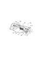
以下、図面に基づいて本発明の実施の形態について詳細に説明する。まず、本発明の第1の実施形態に係るインクジェット式プリンタについて説明する。図1は、本実施の形態に係るインクジェット式プリンタの概略構成を示す斜視図であり、図2は、そのプリントヘッド部におけるブラック(Bk)とカラー(Cl)のノズル列構造を示す図である。 Hereinafter, embodiments of the present invention will be described in detail with reference to the drawings. First, an ink jet printer according to a first embodiment of the present invention will be described. FIG. 1 is a perspective view showing a schematic configuration of an ink jet printer according to the present embodiment, and FIG. 2 is a view showing a nozzle array structure of black (Bk) and color (Cl) in the print head portion. .
図1に示すように、本実施形態のインクジェット式プリンタ20は、キャリッジ30がタイミングベルト36を介してキャリッジ機構12のキャリッジモータ24に接続され、ガイド部材140に案内されて印刷用紙150の紙幅方向に往復動するように構成されている。また、インクジェット式プリンタ20には、紙送りローラ26を用いた紙送り機構11も形成されている。キャリッジ30は印刷用紙150と対向する面、この図に示す例では下面にインクジェット式のプリントヘッド10が取り付けられている。プリントヘッド10はキャリッジ30の上部に載置されているインクカートリッジ170からインクの補給を受けてキャリッジ30の移動に合わせて印刷用紙150に各色のインク滴を吐出してドットを形成し、印刷用紙150に画像や文字を印刷する。尚、この第1の実施形態では、プリントヘッド10は、図2に示すように、ブラック(Bk)インク吐出用のノズル列10Bkとカラーインク吐出用のノズル列10Clとの2つのノズル列を備えている。Bkインク吐出用ノズル列10Bkは、縦(副走査方向)に180個のBkインク吐出用ノズルを有し、カラーインク吐出用ノズル列10Clは、縦(副走査方向)にイエロー(Y)、マゼンタ(M)、シアン(C)の各インク吐出用ノズルをこの順にそれぞれ60個有している。ここで、プリントヘッド10は、図1に示すように、プリンタ装置本体に対して、フレキシブルフラットケーブル(Flexible Flat Cable、以下、FFCと呼ぶ)100を介して回路接続されている。このFFC100は、キャリッジ30の移動を妨げないように、長めのものが用いられている。
As shown in FIG. 1, in the
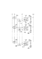
次に、本実施の形態のインクジェット式プリンタ20の電気的構成について説明する。図3は、インクジェット式プリンタ20の機能ブロック図である。図3に示すように、このインクジェット式プリンタ20は、プリンタコントローラ41とプリントエンジン42とを備えている。
Next, the electrical configuration of the
プリンタコントローラ41は、図示しないホストコンピュータ等からの印刷データ等を受信するインタフェース(以下、外部I/Fという)43と、各種データの記憶等を行うRAM44と、各種データ処理のためのルーチン等を記憶したROM45と、CPU等から成る制御部46と、クロック信号(CK)を発生する発振回路47と、プリントヘッド4へ供給する駆動信号(COM)を生成する駆動信号生成回路48と、後に詳述する印字データ(SI)、プログラム(パターン)データ(SP)及び駆動信号等をプリントエンジン42に送信するためのインタフェース(以下、内部I/Fという)49とを備えている。
The
駆動信号生成回路48は、図4及び図5に示すように、中ドット(インク滴の量は約13pl)の第1駆動パルスDP1、小ドット(インク滴の量は約6pl)の第2駆動パルスDP2、中ドット(インク滴の量は約13pl)の第3駆動パルスDP3、無ドット(インク滴の吐出無し)[微振動]の第4駆動パルスDP4を一定の時間間隔で複数配置した駆動信号を印刷周期単位で繰り返し生成する。
As shown in FIGS. 4 and 5, the drive
再び、図3を参照して、外部I/F43は、例えばキャラクタコード、グラフィック関数、イメージデータのいずれか1つ又は複数のデータから成る印刷データをホストコンピュータ等から受信する。また、外部I/F43は、ホストコンピュータに対してビジー信号(BUSY)やアクノリッジ信号(ACK)等を出力する。
Referring to FIG. 3 again, the external I /
RAM44は、入力バッファ、出力バッファ及びワークメモリ等として利用されるものである。入力バッファには、外部I/F43がホストコンピュータ等から受信した印刷データが一時的に記憶される。出力バッファには、プリントヘッド4へシリアル転送される印刷用イメージデータとしての印字データ(SI)が展開される。印字データ(SI)は、ホストコンピュータ(図示せず)等から供給される印刷信号に含まれる印刷データをイメージバッファに展開し、供給された印刷用イメージデータであり、各ノズル列毎に別々に転送される[以下、ブラック(Bk)インク吐出用のノズル列10Bkに転送される印字データを(SIBk)、カラー(Cl)インク吐出用のノズル列10Clに転送される印字データを(SICl)として説明することがある]。ROM45は、制御部46によって実行される各種制御ルーチン、フォントデータ及びグラフィック関数、各種手続き等を記憶している。
The
制御部46は、データ展開手段として機能し、印刷データを印字データに展開する。即ち、入力バッファ内の印刷データを読み出して解析し、ROM45内のフォントデータやグラッフィック関数等を参照して複数ビットの印字データに展開する。尚、本実施形態における印字データは、後述するように2ビットのデータで構成される。この展開された印字データは出力バッファに記憶されて、プリントヘッド10の1行分に相当する印字データが得られると、この1行分の印字データ(SI)は、内部I/F49を介してプリントヘッド10にシリアル伝送される。
The control unit 46 functions as data expansion means and expands print data into print data. That is, the print data in the input buffer is read and analyzed, and is developed into a plurality of bits of print data by referring to the font data, graphic function, etc. in the
また、制御部46は、タイミング信号発生手段の一部を構成し、内部I/F49を通じてプリントヘッド10にラッチ信号(LAT)やチャンネル信号(CH)を供給する。これらのラッチ信号やチャンネル信号は、駆動信号(COM)を構成する第1駆動パルスDP1〜第4駆動パルスDP4の供給開始タイミングを規定する。
The control unit 46 constitutes a part of the timing signal generation means, and supplies a latch signal (LAT) and a channel signal (CH) to the
プリントエンジン42は、紙送り機構11、キャリッジ機構12及びプリントヘッド10から構成されている。紙送り機構11は、図1を参照して説明したように、紙送りモータ(図示せず)及び紙送りローラ26等から成り、印刷用紙150等の記録媒体を順次送り出して副走査を行うものである。キャリッジ機構12は、プリントヘッド10を搭載するキャリッジ30と、このキャリッジ30をタイミングベルト36を介して走行させるキャリッジモータ24等からなり、プリントヘッド10を主走査させるものである。
The print engine 42 includes a
プリントヘッド10は、図2に示したノズル列構造や、圧力発生室、更にはインク流路系等を含む機械的構成の他、駆動回路系51を備えている。このプリントヘッド10の駆動回路系51は、第1シフトレジスタ52及び第2シフトレジスタ53からなるシフトレジスタと、第1ラッチ回路54と第2ラッチ回路55とからなるラッチ回路と、デコーダ56、制御ロジック57と、レベルシフタ58と、スイッチ回路59と、圧電振動子36とを備えて構成されている。そして、各シフトレジスタ52、53、各ラッチ回路54、55、デコーダ56、スイッチ回路59、及び、圧電振動子36は、それぞれプリントヘッド10のBkのノズル列10Bk、Cl(Y、M、C)のノズル列10Clそれぞれの各ノズル開口[Bk1・・・180、及びY1・・・60、M1・・・60、C1・・・60](図2参照)に対応して複数設けられる。例えば、Bkのノズル列10BkとCl(Y、M、C)のノズル列10Clそれぞれが、図6に示すように、第1シフトレジスタ52A〜52Nと、第2シフトレジスタ53A〜53N、第1ラッチ回路54A〜54Nと、第2ラッチ回路55A〜55Nと、デコーダ56A〜56Nと、スイッチ回路59A〜59Nと、圧電振動子36A〜36Nとから構成される。なお、この図6において、レベルシフタ58(図3参照)は省略されているが、このレベルシフタ58も同様に複数設けられている。
The
そして、プリントヘッド10は、プリンタコントローラ41からの印字データ(SI)に基づいてインク滴を吐出する。即ち、プリンタコントローラ41からの印字データ(SI)は、発振回路47からのクロック信号(CK)に同期して、内部I/F49から第1シフトレジスタ52及び第2シフトレジスタ53にシリアル伝送される。この印字データ(SI)は2ビットのデータであり、非記録、小ドット、中ドット、大ドットからなる4階調を表す階調情報によって構成される。本実施形態では、図4からも明らかなように、非記録が階調情報(00)であり、小ドット階調情報(01)であり、中ドットが階調情報(10)であり、大ドットが階調情報(11)である。
Then, the
印字データ(SI)は、各ノズル開口[Bk1・・・180、及びY1・・・60、M1・・・60、C1・・・60](図2参照)毎に設定される。そして、全てのノズル開口に関し、図4及び図5に示すような下位ビット(L)のデータが第1シフトレジスタ52(52A〜52N)に入力され、同様に、全てのノズル開口に関し、図4及び図5に示すような上位ビット(H)のデータが第2シフトレジスタ53(53A〜53N)に入力される。 The print data (SI) is set for each nozzle opening [Bk1... 180, Y1... 60, M1. For all nozzle openings, lower bit (L) data as shown in FIGS. 4 and 5 is input to the first shift register 52 (52A to 52N). Similarly, for all nozzle openings, FIG. And the data of the upper bit (H) as shown in FIG. 5 is inputted to the second shift register 53 (53A to 53N).
図3に示すように、第1シフトレジスタ52には第1ラッチ回路54が電気的に接続され、第2シフトレジスタ53には第2ラッチ回路55が電気的に接続されている。そして、プリンタコントローラ41からのラッチ信号(LAT)が各ラッチ回路54、55に入力されると、第1ラッチ回路54は、図5に示した印字データ(SI)の下位ビット(L)のデータをラッチし、第2ラッチ回路55は、図4及び図5に示した印字データ(SI)の上位ビット(H)のデータをラッチする。このような動作をする第1シフトレジスタ52及び第1ラッチ回路54の組と、第2シフトレジスタ53及び第2ラッチ回路55の組は、それぞれが記憶回路を構成し、デコーダ56に入力される前の印字データ(SI)を一時的に記憶する。
As shown in FIG. 3, a
ここで、駆動信号生成回路48が生成する駆動信号(COM)について説明しておく。本実施形態における駆動信号生成回路48は、図4に示すように、インク滴の量が異なる4つの駆動パルスDP1〜DP4を印刷周期内で配置した一連の駆動信号を生成する。
Here, the drive signal (COM) generated by the drive
この駆動信号(COM)は、期間T1に配置された(つまり、期間T1で発生する)第1駆動パルスDP1と、期間T1の後の期間T2に配置された第2駆動パルスDP2と、期間T2の後の期間T3に配置された第3駆動パルスDP3と、期間T3の後の期間T4に配置された第4駆動パルスDP4とを有し、印刷周期TAで繰り返し発生される信号である。この駆動信号において、第1駆動パルスDP1、第2駆動パルスDP2、第3駆動パルスDP3、及び、第4駆動パルスDP4は、それぞれ図4に示すような波形形状とされており、圧電振動子36に供給されることによりプリントヘッド10のノズル開口から所定量(それぞれ、約13pl、約6pl、約13pl、0pl)のインク滴を吐出させる。即ち、ここで、第1駆動パルスDP1及び第3駆動パルスDP3は、同一のパルス形状を有し、約13plの中程度のインク滴を吐出する。この第1駆動パルスDP1、第3駆動パルスDP3によって得られるドット径は、中程度の大きさになるため、これら第1駆動パルスDP1及び第3駆動パルスDP3を「中ドットパルス」として表現することもできる。第2駆動パルスDP2は、第1駆動パルスDP1や第3駆動パルスDP3よりも小さい台形波から成り、約6plの小さいインク滴を吐出する。この第2駆動パルスDP2によって小さいドット径が得られるため、この第2駆動パルスDP2を「小ドットパルス」として表現し得る。第4駆動パルスDP4は、各色ヘッド部中央のノズル穴付近のインクを微振動させてインクの粘度の増大を防止するためのものであり、この第4駆動パルスDP4によってインク滴は吐出されない。この第4駆動パルスDP4は、「微振動パルス」として表現可能である。
The drive signal (COM) includes a first drive pulse DP1 arranged in the period T1 (that is, generated in the period T1), a second drive pulse DP2 arranged in the period T2 after the period T1, and a period T2. This signal has a third drive pulse DP3 arranged in the subsequent period T3 and a fourth drive pulse DP4 arranged in the period T4 after the period T3, and is repeatedly generated at the printing cycle TA. In this drive signal, the first drive pulse DP1, the second drive pulse DP2, the third drive pulse DP3, and the fourth drive pulse DP4 each have a waveform shape as shown in FIG. Ink droplets of a predetermined amount (about 13 pl, about 6 pl, about 13 pl, and 0 pl, respectively) are ejected from the nozzle openings of the
次に、4ビットのパルス選択情報をスイッチ回路59等に与える構成について、図4を参照しつつ説明する。
Next, a configuration for giving 4-bit pulse selection information to the
まず、出力バッファ4Cに記憶された各ノズル毎の2ビットの印字データ(SI)[H,L]は、プリントヘッド10内のデコーダ56によって、上述した4ビットのパルス選択情報(D1,D2,D3,D4)に翻訳される。ここで、D1は、第1駆動パルスDP1の選択信号、D2は、第2駆動パルスDP2の選択信号、D3は、第3駆動パルスDP3の選択信号、D4は、第4駆動パルスDP4の選択信号である。この4ビットのパルス選択情報は、一印刷周期内にプリントヘッド10の各ノズルに対応したスイッチ回路59に与えられる。尚、図5に示すように、全ノズルについての2ビットの印字データ(SI)は、一印刷周期内で各シフトレジスタ52、53に転送され、次のラッチ信号によって各ラッチ回路54、55にラッチされる。即ち、ある印刷周期で実行されるべき印字データ(SI)は、直前の印刷周期内でプリントヘッド10に転送される。
First, the 2-bit print data (SI) [H, L] for each nozzle stored in the output buffer 4C is received by the
そして、転送された印字データ(SI)は、各駆動パルスの発生タイミングに応じて4ビットのパルス選択情報に翻訳される。各駆動パルスの発生タイミングは、図5に示すチャンネル信号(CH)とラッチ信号(LAT)によって検出される。即ち、第1駆動パルスDP1の発生タイミングはラッチ信号(LAT)によって、第2駆動パルスDP2の発生タイミングはチャンネル信号(CH1)によって、第3駆動パルスDP3の発生タイミングはチャンネル信号(CH2)によって、第4駆動パルスDP4の発生タイミングはチャンネル信号(CH3)によって、それぞれ検出される。 Then, the transferred print data (SI) is translated into 4-bit pulse selection information according to the generation timing of each drive pulse. The generation timing of each drive pulse is detected by a channel signal (CH) and a latch signal (LAT) shown in FIG. That is, the generation timing of the first drive pulse DP1 is determined by the latch signal (LAT), the generation timing of the second drive pulse DP2 is determined by the channel signal (CH1), and the generation timing of the third drive pulse DP3 is determined by the channel signal (CH2). The generation timing of the fourth drive pulse DP4 is detected by the channel signal (CH3).
各駆動パルスの発生が検出されると、デコーダ56は、当該パルスに対応した選択信号をスイッチ回路59に出力する。即ち、例えば、ラッチ信号(LAT)によって第1駆動パルスDP1の発生が検出された時には、ノズル毎にD1のデータを出力し、チャンネル信号(CH1)によって第2駆動パルスDP2の発生が検出された時には、ノズル毎にD2のデータを出力する。これにより、例えば、ノズルに与えられたD1の値が「1」の場合は、第1駆動パルスDP1に従って圧電振動子36が伸縮するため、該ノズルから約13pl相当のインク滴が吐出され、このインク滴が記録紙に着弾して中ドットの記録ドットが形成される。
一方、与えられたD1の値が「0」であるノズルは、第1駆動パルスDP1が圧電振動子36に印加されないため、インク滴を吐出しない。
When the generation of each drive pulse is detected, the
On the other hand, since the first drive pulse DP1 is not applied to the
以上のように、4段階のドット階調を行う場合、特開平10−81013号公報に記載されているように、真理値表に対応するプログラム(パターン)データ(SP)を組み合わせ回路等に入力することを介して印字データ(階調値)と駆動パルスとの組み合わせを自由に設定することが可能である。この時、2値の印字データを転送するごとに、16ビットのプログラム(パターン)データ(SP)を送ることが考えられる。図4(B)は、かかるプログラム(パターン)データ(SP)の16ビットの構成を示す。即ち、プログラム(パターン)データ(SP)は、印字データ(SI)と選択される駆動パルスDP1〜DP4との関係を規定するデータであり、例えば、図4(B)に示すように、プログラム(パターン)データ(SP)は、[0001100000101100]から成る16ビットのデータが送られる。ここで、このプログラム(パターン)データ(SP)は、図4(A)に示すように、第4駆動パルスにおける大ドットの印字データ4を最上位ビットデータ(TOP)として、次に、印字データ3、2、1に対応するプログラムデータ(SP)を順次送る。従って、図4(B)示すように、プログラムデータ(SP)は、TOPから(0001)となる。次に、第4の駆動パルスのプログラムデータ(SP)に追従し、第3の駆動パルスの印字データ4から印字データ1までのプログラムデータ(1000)が送られる。以下、第2、第1駆動パルスに対応するプログラムデータが送られ、図4(A)に示すように、最下位のビットデータ(BOTTOM)までを順次送る。従って、図4(B)示すように、プログラムデータ(SP)は、[0001100000101100]の16ビットから成るパルス選択情報となる。以上のように、駆動パルス毎にまとめてプログラムデータ(SP)を送ることで、印字周期内の時系列毎に駆動パルスの生成が可能となるため、効率よく駆動データを構成することができる。また、上記では第4駆動パルスにおける大ドットの印字データ4を最上位ビットデータ(TOP)としたが、印字周期内の時系列毎に駆動パルスを生成できれば良く、従って、第1駆動パルスにおける微振動の印字データ1を最上位ビットデータ(TOP)とし、第4駆動パルスにおける大ドットの印字データ4を最下位のビットデータ(BOTTOM)としても良い。
As described above, when four-step dot gradation is performed, program (pattern) data (SP) corresponding to a truth table is input to a combinational circuit or the like as described in JP-A-10-81013. By doing so, it is possible to freely set the combination of the print data (gradation value) and the drive pulse. At this time, it is conceivable to send 16-bit program (pattern) data (SP) each time binary print data is transferred. FIG. 4B shows a 16-bit configuration of such program (pattern) data (SP). That is, the program (pattern) data (SP) is data defining the relationship between the print data (SI) and the selected drive pulses DP1 to DP4. For example, as shown in FIG. Pattern) data (SP) is 16-bit data consisting of [0001100000101100]. Here, as shown in FIG. 4A, the program (pattern) data (SP) includes the large
以上により、上記のプログラム(パターン)データ(SP)に基づいて、図4(A)に示すように、各印字データ(SI)[H,L]に対応したパルス選択情報が得られる。即ち、印字データ(00)には、パルス選択情報(0001)、印字データ(01)には、パルス選択情報(0100)、印字データ(10)には、パルス選択情報(1000)、印字データ(11)には、パルス選択情報(1010)が、それぞれ対応して得られる。これらパルス選択情報は、駆動信号(COM)を構成する各駆動パルスDP1〜DP4に各ビットを対応させた複数ビットで構成されている。そして、各ビットの内容〔例えば、(0)、(1)〕に応じて圧電振動子36に対する各駆動パルスの供給あるいは非供給が選択される。即ち、パルス選択情報の最上位ビットが第1駆動パルスDP1に対応し、2番目のビットが第2駆動パルスDP2に対応し、3番目のビットが第3駆動パルスDP3に対応し、最下位ビットが第4駆動パルスDP4に対応している。そして、パルス選択情報の最上位ビットが(1)の場合には、最初のタイミング信号の発生時である期間T1の開始時から2番目のタイミング信号の発生時である期間T2の開始時までの間スイッチ回路59が接続状態になる。2番目のビットが(1)の場合には、期間T2の開始時から3番目のタイミング信号の発生時である期間T3の開始時までの間スイッチ回路59が接続状態になる。3番目のビットが(1)の場合には、期間T3の開始時から4番目のタイミング信号の発生時である期間T4の開始時までの間スイッチ回路59が接続状態になる。同様に、最下位ビットが(1)の場合には、期間T4の開始時から次の印刷周期TAにおける期間T1の開始時までの間スイッチ回路59が接続状態になる。
As described above, pulse selection information corresponding to each print data (SI) [H, L] is obtained based on the program (pattern) data (SP) as shown in FIG. That is, the print data (00) includes pulse selection information (0001), the print data (01) includes pulse selection information (0100), the print data (10) includes pulse selection information (1000), and print data ( 11), pulse selection information (1010) is obtained correspondingly. The pulse selection information is composed of a plurality of bits in which each bit corresponds to each drive pulse DP1 to DP4 constituting the drive signal (COM). Then, supply or non-supply of each drive pulse to the
従って、小ドットの印字データ(01)に基づき、対応する圧電振動子36には、第2駆動パルスDP2が供給される。同様に、中ドットの印字データ(10)に基づいて、対応する圧電振動子36には、第1駆動パルスDP1が供給され、大ドットの印字データ(11)に基づいて、対応する圧電振動子36には、第1駆動パルスDP1及び第3駆動パルスDP3が供給される。
Accordingly, the second drive pulse DP2 is supplied to the corresponding
図5は、16ビットのプログラム(パターン)データ(SP)を駆動信号と共に表したタイミングチャートであり、かかるプログラム(パターン)データ(SP)の転送方法を示す。同図に示すように、16ビットのプログラム(パターン)データ(SP)は、上位ビット180(H DATA)及び下位ビット180(L DATA)から成る印字データ(SI)の後に続く16ビットデータにより構成されており、図3に示すように、FFC100内の印字データ(SI)と共通の信号線によりプリンタ装置本体内のプリンタコントローラ41からプリントヘッド10に転送される。
FIG. 5 is a timing chart showing 16-bit program (pattern) data (SP) together with a drive signal, and shows a method of transferring the program (pattern) data (SP). As shown in the figure, 16-bit program (pattern) data (SP) is composed of 16-bit data following print data (SI) consisting of upper bits 180 (H DATA) and lower bits 180 (L DATA). As shown in FIG. 3, the print data (SI) in the
この方式では、図5に示すように、多値データの転送を、ブラック(Bk)とカラー(Cl)それぞれのノズル列ごとに(印刷データSIBk、SIClそれぞれにおいて)上位ビット180(H DATA)、続けて下位ビット180(L DATA)を180×2=360クロックで転送している。この方式では、2列ヘッドそれぞれのTGには、印字データSIは、SIBk、SIClそれぞれが転送され、プログラムデータ(SP)も、SIBkの後に続いて16ビットデータSPBkが転送され、SIClの後に続いて16ビットデータSPClが転送される。ここで、本実施形態では、2個のTGそれぞれに対して共通のプログラム(パターン)データ(SP)が転送される[SPBk=SPCl](インクの色がBkとカラー如何に拘らず多値パターンは共通のパターンとなる)。 In this method, as shown in FIG. 5, the transfer of multi-value data is performed for each nozzle row of black (Bk) and color (Cl) (in the print data SIBk and SICl), the upper bit 180 (H DATA), Subsequently, the lower bit 180 (L DATA) is transferred at 180 × 2 = 360 clocks. In this method, the print data SI is transferred to each of the TGs of the two-row heads, SIBk and SICl, respectively, and the program data (SP) is also transferred to the 16-bit data SPBk after the SIBk, and after the SICl. 16-bit data SPCl is transferred. Here, in this embodiment, common program (pattern) data (SP) is transferred to each of the two TGs [SPBk = SPCl] (a multi-value pattern regardless of whether the ink color is Bk or color). Is a common pattern).
さて、制御部46は、ホストコンピュータ等からの印刷データを2ビットの階調情報から成る印字データ(SI)に展開し、プリントヘッド10にシリアル伝送する。
The control unit 46 expands the print data from the host computer or the like into print data (SI) composed of 2-bit gradation information and serially transmits it to the
例えば、制御部46は、印刷データを、非印字の印字データ(階調情報00)、小ドットの印字データ(階調情報01)、中ドットの印字データ(階調情報10)、或いは、大ドットの印字データ(階調情報11)に展開する。展開された印字データは、1ノズル列分、即ち、上位ビット180(H DATA)及び下位ビット180(L DATA)から成る印字データ(SI)として転送されるが、この180×2=360個のSIデータの後に続く16ビットデータによりSPデータが構成されており、図3に示したように、FFC100内の印字データ(SI)と共通の信号線によりプリンタ装置本体内のプリンタコントローラ41からプリントヘッド10に転送される。かかるSIデータとその後に続くSPデータから成る多値データSISPは、SIデータ部分がプリントヘッド10のシフトレジスタ52、53にセットされた後に、ラッチ信号のタイミングでラッチ回路54、55にラッチされる。一方、SISPのSPデータ部分は、印字データ(SI)と選択される駆動パルスDP1〜DP4との関係を規定するデータであり、印字データ(SI)に連続してプリントヘッド10にシリアル転送され、第3シフトレジスタ60にセットされた後にラッチ信号LATにより確定されて、制御ロジック57に入力される。この制御ロジック57は、例えば、前述した特開平10−81013号公報に記載されている組み合わせ回路等と同様の公知の構成を用いることができる。
For example, the control unit 46 sets the print data as non-print print data (gradation information 00), small dot print data (gradation information 01), medium dot print data (gradation information 10), or large print data. This is expanded into dot print data (gradation information 11). The developed print data is transferred as print data (SI) consisting of one nozzle row, that is, upper bits 180 (H DATA) and lower bits 180 (L DATA). The 180 × 2 = 360 pieces of print data are transferred. The SP data is composed of 16-bit data following the SI data. As shown in FIG. 3, the print head is connected from the
各ラッチ回路54、55でラッチされた印字データは、デコーダ56に入力される。このデコーダ56は翻訳手段として機能し、2ビットの印字データを翻訳してパルス選択情報を生成する。本実施形態のデコーダ56には、制御ロジック57から上述したパルス選択信号が入力されており、このパルス選択信号に基づいてパルス選択情報を生成する。
The print data latched by the
デコーダ56によって翻訳されたパルス選択情報は、上位ビット側から順に、タイミング信号によって規定されるタイミングが到来する毎にレベルシフタ58に入力される。例えば、印刷周期TAにおける最初のタイミング(T1の開始時)ではパルス選択情報の最上位ビットのデータがレベルシフタ58に入力され、2番目のタイミング(T2の開始時)ではパルス選択情報における2番目のビットのデータがレベルシフタ58に入力される。このレベルシフタ58は、電圧増幅器として機能し、パルス選択情報が(1)の場合には、スイッチ回路59を駆動できる電圧、たとえは数十ボルト程度の電圧に昇圧された電気信号を出力する。レベルシフタ58で昇圧された(1)のパルス選択情報は、スイッチ手段として機能するスイッチ回路59に供給される。このスイッチ回路59の入力側には、駆動信号生成回路48からの駆動信号(COM)が供給されており、スイッチ回路59の出力側には圧電振動子36が接続されている。
The pulse selection information translated by the
パルス選択情報は、スイッチ回路59の作動、つまり、第1〜第4駆動パルスDP1〜DP4の圧電振動子36への選択的な供給を制御する。例えば、スイッチ回路59に加わるパルス選択情報が(1)である期間中は、スイッチ回路59が接続状態になって当該駆動パルスが圧電振動子36に供給され、この駆動パルスに応じて圧電振動子36の電位レベルが変化する。一方、スイッチ回路59に加わるパルス選択情報が、(0)の期間中は、レベルシフタ58からはスイッチ回路59を作動させる電気信号が出力されない。このため、スイッチ回路59が切断状態になって圧電振動子36へは駆動パルスが供給されない。
The pulse selection information controls the operation of the
従って、図4(A)に示すように、パルス選択情報如何により、第1駆動パルスDP1、第2駆動パルスDP2、第3駆動パルスDP3、及び/又は第4駆動パルスDP4を選択的に圧電振動子36に供給することができ、これにより、プリントヘッド10のノズル開口からそれぞれ所定量(約13pl、約6pl、約13pl、0pl)のインク滴を吐出させることが可能である。
Therefore, as shown in FIG. 4A, the first drive pulse DP1, the second drive pulse DP2, the third drive pulse DP3, and / or the fourth drive pulse DP4 is selectively piezoelectrically oscillated according to the pulse selection information. Thus, a predetermined amount (about 13 pl, about 6 pl, about 13 pl, 0 pl) of ink droplets can be ejected from the nozzle openings of the
本実施形態によれば、プログラム(パターン)データ(SP)を、印字データ(SI)の後に続くデータにより構成し、FFC100内の印字データ(SI)と共通の信号線によりプリンタ装置本体内のプリンタコントローラ41からプリントヘッド10に転送するので、プログラム(パターン)データ(SP)を送るための信号線を別個設ける必要が無くなる結果、FFC100内の信号線数を削減することが可能である。
According to the present embodiment, the program (pattern) data (SP) is constituted by the data that follows the print data (SI), and the printer in the printer apparatus main body is formed by the common signal line with the print data (SI) in the
次に、本発明の第2の実施形態に係るインクジェット式プリンタについて説明する。この第2の実施形態に係るインクジェット式プリンタの基本構成は、図1、図2及び図3に示した第1の実施形態のものと略同様であるので、その図示及び詳しい説明は省略する。 Next, an ink jet printer according to a second embodiment of the present invention will be described. Since the basic configuration of the ink jet printer according to the second embodiment is substantially the same as that of the first embodiment shown in FIGS. 1, 2, and 3, the illustration and detailed description thereof will be omitted.
本実施形態の特徴は、図7(A)及び(B)に示すように、BkとClの2個のTGそれぞれに対して異なるプログラム(パターン)データ(SP)を転送する[図5において、SPBk≠SPCl](インクの色がBkとカラーとで多値パターンは別個のパターンとなる)ことにある。 As shown in FIGS. 7A and 7B, the feature of this embodiment is that different program (pattern) data (SP) is transferred to each of two TGs Bk and Cl [in FIG. SPBk ≠ SPCl] (the ink color is Bk and color, and the multi-value pattern is a separate pattern).
即ち、図7(B)に示すように、Clのプログラム(パターン)データ(SPCl)は、[0001100000101100]から成る16ビットのデータが送られるのに対し、Bkのプログラム(パターン)データ(SPBk)は、[0001101000001100]から成る16ビットのデータが送られる。ここで、これらプログラム(パターン)データ(SPCl及びSPBk)は、図7(A)に示すように、最上位ビットデータ(TOP)から最下位ビットデータ(BOTTOM)までの16ビットが構成されている。 That is, as shown in FIG. 7B, the program (pattern) data (SPCl) of Cl is 16-bit data consisting of [0001100000101100], whereas the program (pattern) data (SPBk) of Bk. 16-bit data consisting of [0001101000001100] is sent. Here, as shown in FIG. 7A, these program (pattern) data (SPCl and SPBk) are composed of 16 bits from the most significant bit data (TOP) to the least significant bit data (BOTTOM). .
従って、まず、Clインクのプログラム(パターン)データ(SPCl)に基づいて、図7(A)に示すように、各印字データ(SICl)[H,L]に対応したパルス選択情報が得られる。即ち、印字データ(00)には、パルス選択情報(0001)、印字データ(01)には、パルス選択情報(0100)、印字データ(10)には、パルス選択情報(1000)、印字データ(11)には、パルス選択情報(1010)が、それぞれ対応して得られる。 Therefore, first, as shown in FIG. 7A, pulse selection information corresponding to each print data (SICl) [H, L] is obtained based on the Cl ink program (pattern) data (SPCl). That is, the print data (00) includes pulse selection information (0001), the print data (01) includes pulse selection information (0100), the print data (10) includes pulse selection information (1000), and print data ( 11), pulse selection information (1010) is obtained correspondingly.
一方、Bkインクのプログラム(パターン)データ(SPBk)に基づいて、図7(A)に示すように、各印字データ(SIBk)[H,L]に対応したパルス選択情報が得られる。即ち、印字データ(00)には、パルス選択情報(0001)、印字データ(01)には、パルス選択情報(0010)、印字データ(10)には、パルス選択情報(1000)、印字データ(11)には、パルス選択情報(1010)が、それぞれ対応して得られる。 On the other hand, based on the Bk ink program (pattern) data (SPBk), as shown in FIG. 7A, pulse selection information corresponding to each print data (SIBk) [H, L] is obtained. That is, the print data (00) includes pulse selection information (0001), the print data (01) includes pulse selection information (0010), the print data (10) includes pulse selection information (1000), and print data ( 11), pulse selection information (1010) is obtained correspondingly.
ここで、本実施形態のインクジェット式プリンタによる作用効果を説明する。まず、Clインクの印字データ(SICl)とプログラム(パターン)データ(SPCl)による吐出制御方法及びその作用は、図4及び図7を比較すれば明らかなように、上述した第1の実施形態の場合と全く同様であるので、その説明は省略する。 Here, the operational effects of the ink jet printer according to the present embodiment will be described. First, as is apparent from a comparison of FIGS. 4 and 7, the ejection control method and its operation using Cl ink print data (SICl) and program (pattern) data (SPCl) are the same as those in the first embodiment described above. Since this is exactly the same as the case, the description thereof is omitted.
一方、図7に示す例では、Bkのプログラム(パターン)データ(SPBk)は、[0001101000001100]から成る16ビットのデータが送られる結果、印字データSIBkが(00)では、「微振動パルス」たる第4駆動パルスDP4が選択される結果、当該ノズルからインク滴は吐出されず、ドットは形成されない(非記録)。SIBkが(01)では、中ドットパルスたる第3駆動パルスDP3が選択される結果、当該ノズルから約13pl相当のインク滴が吐出され、このインク滴が記録紙に着弾し、中ドットの記録ドットが(後ろ)に形成される。SIBkが(10)では、中ドットパルスたる第1駆動パルスDP1が選択される結果、当該ノズルから約13pl相当のインク滴が吐出され、このインク滴が記録紙に着弾し、中ドットの記録ドットが(前)に形成される。SIBkが(11)では、中ドットパルスたる第1駆動パルスDP1と同じく中ドットパルスたる第3駆動パルスDP3の両者が選択される結果、同一ノズルから約13pl相当のインク滴が2つ吐出され、これらインク滴が記録紙に着弾し、合体して大ドットの記録ドットが形成される。 On the other hand, in the example shown in FIG. 7, Bk program (pattern) data (SPBk) is 16 bit data consisting of [0001101000001100]. As a result, when the print data SIBk is (00), “fine vibration pulse” is generated. As a result of the selection of the fourth drive pulse DP4, no ink droplet is ejected from the nozzle, and no dot is formed (non-recording). When SIBk is (01), the third drive pulse DP3, which is a medium dot pulse, is selected. As a result, an ink droplet equivalent to about 13 pl is ejected from the nozzle, and this ink droplet lands on the recording paper. Is formed on the back. When the SIBk is (10), the first drive pulse DP1, which is a medium dot pulse, is selected. As a result, an ink droplet equivalent to about 13 pl is ejected from the nozzle, and the ink droplet lands on the recording paper. Is formed (before). When SIBk is (11), both the first drive pulse DP1 that is a medium dot pulse and the third drive pulse DP3 that is a medium dot pulse are selected. As a result, two ink droplets corresponding to about 13 pl are ejected from the same nozzle, These ink droplets land on the recording paper and combine to form a large dot recording dot.
このように、Bkインクの印字データ(SIBk)とプログラム(パターン)データ(SPBk)による吐出制御において、中ドットの記録制御が一印刷周期TA内の前半ドット(第1駆動パルスDP1による場合、つまり、前側の単位画素)及び後半ドット(第3駆動パルスDP3による場合、つまり、後側の単位画素)の記録又は非記録を表すパルス選択情報に従って形成される。 As described above, in the ejection control based on the Bk ink print data (SIBk) and the program (pattern) data (SPBk), the medium dot recording control is performed in the first half dot within one printing cycle TA (that is, when the first drive pulse DP1 is used). , The front unit pixel) and the latter half dot (in the case of the third drive pulse DP3, that is, the rear unit pixel), it is formed according to pulse selection information indicating recording or non-recording.
従って、図7(A)から分かるように、印字データ(SIBk)の上位ビット(H)が前半ドットに割り当てられてこの前半ドットの記録又は非記録を表し、印字データ(SIBk)の下位ビット(L)が後半ドットに割り当てられてこの後半ドットの記録又は非記録を表すのと同様になる。例えば、印字データSIBk(00)は前半ドットと後半ドットの何れも記録しない(0pl)ことを意味し、印字データSIBk(10)は前半ドットのみを記録する(13pl前)ことを意味し、印字データSIBk(11)は前半ドットと後半ドットを連続して記録する(26pl)ことを意味する。 Accordingly, as can be seen from FIG. 7A, the upper bit (H) of the print data (SIBk) is assigned to the first half dot to indicate recording or non-recording of the first half dot, and the lower bit ( L) is assigned to the latter half of the dot and represents the recording or non-recording of the latter half of the dot. For example, the print data SIBk (00) means that neither the first half dot nor the second half dot is recorded (0 pl), and the print data SIBk (10) means that only the first half dot is recorded (before 13 pl). Data SIBk (11) means that the first half dot and the second half dot are continuously recorded (26 pl).
図8は、本発明の第2の実施の形態に係るインクジェット式プリンタの作用・効果を説明するための図であり、図7(A)に示したパルス選択情報によって、カラー(Cl)のインク滴(6pl,13pl,26pl)とブラック(Bk)のインク滴(13pl後,13pl前,26pl)それぞれが吐出されドットを形成する様子を示す。 FIG. 8 is a diagram for explaining the operation and effect of the ink jet printer according to the second embodiment of the present invention. Color (Cl) ink is determined based on the pulse selection information shown in FIG. A state is shown in which droplets (6 pl, 13 pl, 26 pl) and black (Bk) ink droplets (after 13 pl, before 13 pl, 26 pl) are ejected to form dots.
図8、特に、Bkの(13pl後,13pl前)に関して斜線部で示すように、Bkインクに関しては、一印刷周期TA(360dpi)に対応した記録領域内に2つの単位画素(高解像度単位画素)を主走査方向に沿って記録可能となり、あたかも、主走査方向の解像度をClの2倍(720dpi)に設定したかのような状態となる。つまり、この場合、Clにおける単位画素形成領域内に、Bkでは2つの高解像度単位画素を記録できる。 In FIG. 8, in particular, as indicated by the hatched portion with respect to Bk (after 13 pl, before 13 pl), for Bk ink, two unit pixels (high resolution unit pixels) are included in the recording area corresponding to one printing cycle TA (360 dpi). ) Can be recorded along the main scanning direction, as if the resolution in the main scanning direction was set to twice Cl (720 dpi). That is, in this case, two high-resolution unit pixels can be recorded in Bk in the unit pixel formation region in Cl.
以上のように、本実施形態では、BkとClの2個のTGそれぞれに対して異なるプログラム(パターン)データ(SP)を転送するようにすることで、BkとClとで、解像度を異ならしめる等、プログラマブルな吐出制御が可能となる。 As described above, in the present embodiment, by transferring different program (pattern) data (SP) to each of the two TGs Bk and Cl, the resolution differs between Bk and Cl. For example, programmable discharge control can be performed.
以上説明したように、本発明によれば、プログラム(パターン)データを印字データと共通の信号線によりプリンタ装置本体からプリントヘッドに転送するので、プログラム(パターン)データを送るための信号線を別個設ける必要が無くなる。従って、例えば、FFC内の信号線数を削減することが可能であり、比較的低コストで、インクジェット式プリンタを製作できる上に、FFCの配線取り回し等も容易になる。 As described above, according to the present invention, since the program (pattern) data is transferred from the printer apparatus main body to the print head via the signal line common to the print data, the signal line for sending the program (pattern) data is separately provided. There is no need to provide it. Therefore, for example, the number of signal lines in the FFC can be reduced, an inkjet printer can be manufactured at a relatively low cost, and wiring of the FFC can be easily performed.
また、本発明によれば、少なくとも1色について、他の色とは異なるプログラム(パターン)データを用いるので、例えば、当該1色について解像度を異ならしめる等、インクジェット式プリンタにおけるプログラマブルな吐出制御が可能となる。 In addition, according to the present invention, since program (pattern) data different from that of other colors is used for at least one color, for example, it is possible to perform programmable ejection control in an ink jet printer, such as making the resolution different for the one color. It becomes.
以上、本発明を特定の実施形態について述べたが、本発明はこれらに限られるものではなく、特許請求の範囲に記載した範囲内で他の実施形態についても適用される。 As mentioned above, although this invention was described about specific embodiment, this invention is not limited to these, It applies also about other embodiment within the range described in the claim.
例えば、上記実施形態では、プリントヘッド10がブラック(Bk)インク吐出用のノズル列とカラーインク吐出用のノズル列との2つのノズル列を備える例について説明したが、ノズル列の数は2つに限られない。例えば、1列96ノズル、7列ヘッドで2ビット多値データを転送する場合等にも本発明を適用し得るのは勿論である。
For example, in the above-described embodiment, an example in which the
尚、上述した実施形態では、圧力発生素子としてはピエゾ素子を用いたが、ピエゾ素子に限らず、磁歪素子等を用いてもよい。さらに、本発明は、圧力発生素子として発熱素子を用いたいわゆるバブルジェット(登録商標)方式のインクジェット式プリンタにも適用することができる。 In the embodiment described above, a piezoelectric element is used as the pressure generating element. However, the pressure generating element is not limited to the piezoelectric element, and a magnetostrictive element or the like may be used. Furthermore, the present invention can also be applied to a so-called bubble jet (registered trademark) ink jet printer using a heating element as a pressure generating element.
20 インクジェット式プリンタ、10 プリントヘッド、10Bk ブラックインク吐出用のノズル列、10Cl カラーインク吐出用のノズル列、100 フレキシブルフラットケーブル(FFC)、41 プリンタコントローラ、42 プリントエンジン、48 駆動信号生成回路、DP1 第1駆動パルス、DP2 第2駆動パルス、DP3 第3駆動パルス、DP4 第4駆動パルス、46 制御部、52 第1シフトレジスタ、53 第2シフトレジスタ、54 第1ラッチ回路、55 第2ラッチ回路、56 デコーダ、57 制御ロジック、58 レベルシフタ、59 スイッチ回路、36 圧電振動子、SI 印字データ、SP プログラム(パターン)データ、CH チャンネル信号、LAT ラッチ信号、60 第3シフトレジスタ。 20 Inkjet printer, 10 Print head, 10Bk Black ink ejection nozzle array, 10Cl color ink ejection nozzle array, 100 Flexible flat cable (FFC), 41 Printer controller, 42 Print engine, 48 Drive signal generation circuit, DP1 1st drive pulse, DP2 2nd drive pulse, DP3 3rd drive pulse, DP4 4th drive pulse, 46 control unit, 52 1st shift register, 53 2nd shift register, 54 1st latch circuit, 55 2nd latch circuit , 56 decoder, 57 control logic, 58 level shifter, 59 switch circuit, 36 piezoelectric vibrator, SI print data, SP program (pattern) data, CH channel signal, LAT latch signal, 60 third shift register.
Claims (4)
前記プリントヘッドが取り付けられて移動するキャリッジと、
前記駆動素子を作動させるために、一印刷周期内に異なる複数の駆動パルスを生成する制御部を有するプリンタ本体と、
を備え、
印刷用イメージデータとしての複数ビットの印字データ、及び、
前記複数の駆動パルスから選択される駆動パルスと、前記印字データとの、対応関係を規定する複数ビットのパターンデータ、
から選択された前記駆動パルスが複数の前記駆動素子に印加されるように構成されたインクジェット式プリンタにおいて、
前記プリンタ本体は、前記制御部が前記プリントヘッドに複数ビットの前記印字データと、前記印字データの後に続くデータ構成とした複数ビットの前記パターンデータと、をシリアル転送するよう構成され、
前記プリントヘッドは、前記連続してシリアル転送される複数ビットの前記印字データを記憶する印字データ記憶用シフトレジスタと、前記印字データ記憶用シフトレジスタに接続され前記パターンデータを記憶するパターンデータ記憶用シフトレジスタと、前記印字データ記憶用シフトレジスタで記憶された前記印字データと前記パターンデータ記憶用シフトレジスタで記憶された前記パターンデータとから前記駆動パルスを選択するパルス選択手段と、を備えたことを特徴とするインクジェット式プリンタ。 A print head that ejects ink droplets from each nozzle by operating a driving element provided corresponding to each of the plurality of nozzles;
A carriage on which the print head is mounted and moved;
A printer main body having a control unit for generating a plurality of different drive pulses within one printing cycle in order to operate the drive element;
With
Multi-bit print data as print image data , and
A plurality of bit pattern data defining a correspondence relationship between the drive pulse selected from the plurality of drive pulses and the print data;
In the ink jet printer configured to apply the driving pulse selected from a plurality of the driving elements,
The printer main body is configured such that the control unit serially transfers the print data of a plurality of bits to the print head and the pattern data of a plurality of bits having a data configuration that follows the print data.
The print head is connected to the print data storage shift register for storing the print data of a plurality of bits transferred serially serially, and for pattern data storage connected to the print data storage shift register. A shift register; and pulse selection means for selecting the drive pulse from the print data stored in the print data storage shift register and the pattern data stored in the pattern data storage shift register. An ink jet printer characterized by the above.
前記プリントヘッドが取り付けられて移動するキャリッジと、
前記駆動素子を作動させるために、一印刷周期内に異なる複数の駆動パルスを生成する制御部を有するプリンタ本体と、
を備え、
印刷用イメージデータとしての複数ビットの印字データ、及び、
前記複数の駆動パルスから選択される駆動パルスと、前記印字データとの、対応関係を規定する複数ビットのパターンデータ、
から選択された前記駆動パルスが複数の前記駆動素子に印加されるように構成されたインクジェット式プリンタを用いた印刷方法において、
前記プリンタ本体は、前記制御部が前記プリントヘッドに複数ビットの前記印字データと、前記印字データの後に続くデータ構成とした複数ビットの前記パターンデータと、をシリアル転送し、
前記プリントヘッドは、
印字データ記憶用シフトレジスタにより、前記連続してシリアル転送される複数ビットの前記印字データを記憶し、
前記印字データ記憶用シフトレジスタに接続されたパターンデータ記憶用シフトレジスタにより、前記パターンデータを記憶し、
パルス選択手段により、前記印字データ記憶用シフトレジスタで記憶された前記印字データと前記パターンデータ記憶用シフトレジスタで記憶された前記パターンデータとから前記駆動パルスを選択することを特徴とする印刷方法。 A print head that ejects ink droplets from each nozzle by operating a driving element provided corresponding to each of the plurality of nozzles;
A carriage on which the print head is mounted and moved;
A printer main body having a control unit for generating a plurality of different drive pulses within one printing cycle in order to operate the drive element;
With
Multi-bit print data as print image data , and
A plurality of bit pattern data defining a correspondence relationship between the drive pulse selected from the plurality of drive pulses and the print data;
In the printing method using the ink jet printer configured to apply the driving pulse selected from the plurality of driving elements,
The printer body serially transfers the print data of a plurality of bits to the print head and the pattern data of a plurality of bits having a data configuration that follows the print data.
The print head is
The print data storage shift register stores the print data of a plurality of bits that are serially transferred continuously,
The pattern data is stored by the pattern data storage shift register connected to the print data storage shift register,
A printing method comprising: selecting the driving pulse from the print data stored in the print data storage shift register and the pattern data stored in the pattern data storage shift register by a pulse selection unit.
Priority Applications (1)
| Application Number | Priority Date | Filing Date | Title |
|---|---|---|---|
| JP2010094759A JP4930622B2 (en) | 2001-04-17 | 2010-04-16 | Inkjet printer and printing method |
Applications Claiming Priority (3)
| Application Number | Priority Date | Filing Date | Title |
|---|---|---|---|
| JP2001118741 | 2001-04-17 | ||
| JP2001118741 | 2001-04-17 | ||
| JP2010094759A JP4930622B2 (en) | 2001-04-17 | 2010-04-16 | Inkjet printer and printing method |
Related Parent Applications (1)
| Application Number | Title | Priority Date | Filing Date |
|---|---|---|---|
| JP2007026074A Division JP2007112149A (en) | 2001-04-17 | 2007-02-05 | Ink jet printer |
Publications (3)
| Publication Number | Publication Date |
|---|---|
| JP2010155470A JP2010155470A (en) | 2010-07-15 |
| JP2010155470A5 JP2010155470A5 (en) | 2010-09-09 |
| JP4930622B2 true JP4930622B2 (en) | 2012-05-16 |
Family
ID=42573724
Family Applications (1)
| Application Number | Title | Priority Date | Filing Date |
|---|---|---|---|
| JP2010094759A Expired - Lifetime JP4930622B2 (en) | 2001-04-17 | 2010-04-16 | Inkjet printer and printing method |
Country Status (1)
| Country | Link |
|---|---|
| JP (1) | JP4930622B2 (en) |
Cited By (1)
| Publication number | Priority date | Publication date | Assignee | Title |
|---|---|---|---|---|
| US10933633B2 (en) | 2015-11-30 | 2021-03-02 | Seiko Epson Corporation | Liquid ejecting device and ejection selection signal generation circuit |
Families Citing this family (2)
| Publication number | Priority date | Publication date | Assignee | Title |
|---|---|---|---|---|
| JP2022151262A (en) | 2021-03-26 | 2022-10-07 | セイコーエプソン株式会社 | Liquid discharge device |
| JP2022151260A (en) | 2021-03-26 | 2022-10-07 | セイコーエプソン株式会社 | Liquid discharge device |
Family Cites Families (4)
| Publication number | Priority date | Publication date | Assignee | Title |
|---|---|---|---|---|
| JP3965845B2 (en) * | 1999-11-18 | 2007-08-29 | セイコーエプソン株式会社 | Inkjet recording device |
| JP3837296B2 (en) * | 2000-01-25 | 2006-10-25 | セイコーエプソン株式会社 | Inkjet recording device |
| JP3467570B2 (en) * | 2000-08-04 | 2003-11-17 | セイコーエプソン株式会社 | Liquid ejecting apparatus and driving method of liquid ejecting apparatus |
| JP4141992B2 (en) * | 2004-07-27 | 2008-08-27 | セイコーエプソン株式会社 | Inkjet recording apparatus and recording method |
-
2010
- 2010-04-16 JP JP2010094759A patent/JP4930622B2/en not_active Expired - Lifetime
Cited By (1)
| Publication number | Priority date | Publication date | Assignee | Title |
|---|---|---|---|---|
| US10933633B2 (en) | 2015-11-30 | 2021-03-02 | Seiko Epson Corporation | Liquid ejecting device and ejection selection signal generation circuit |
Also Published As
| Publication number | Publication date |
|---|---|
| JP2010155470A (en) | 2010-07-15 |
Similar Documents
| Publication | Publication Date | Title |
|---|---|---|
| JP3944712B2 (en) | Inkjet printer | |
| US6419337B2 (en) | Ink jet recording apparatus and method of driving the same | |
| JP5471289B2 (en) | Liquid ejecting apparatus and method for controlling liquid ejecting apparatus | |
| US7278698B2 (en) | Liquid ejection apparatus, liquid ejection head thereof, and liquid ejection method | |
| EP1120256B1 (en) | Ink jet recording apparatus, method of controlling the apparatus, and recording medium having the method recorded thereon | |
| KR100693022B1 (en) | Driving circuit of inkjet recording head, inkjet recording head and inkjet printer | |
| JP4930622B2 (en) | Inkjet printer and printing method | |
| JP3634355B2 (en) | Liquid ejector | |
| JP3965845B2 (en) | Inkjet recording device | |
| EP3383660B1 (en) | Liquid ejecting device and ejection selection signal generation circuit | |
| JP2001246738A (en) | Ink-jet recording apparatus and method for driving ink- jet recording head | |
| JP2005081565A (en) | Liquid injection apparatus | |
| JP2001315324A (en) | Ink jet recorder | |
| JP3508724B2 (en) | Ink jet recording device | |
| JP3837296B2 (en) | Inkjet recording device | |
| JP5298766B2 (en) | Liquid ejection device | |
| JP2007131012A (en) | Recording apparatus | |
| JP2007112149A (en) | Ink jet printer | |
| JP4470506B2 (en) | Print control device | |
| JP2007015166A (en) | Recording device | |
| JP2005067073A (en) | Liquid ejector | |
| JP5332086B2 (en) | Printing apparatus, printing method, and program | |
| JP2005035066A (en) | Ink jet printer, its head driver and driving method | |
| JP2005067086A (en) | Liquid ejector | |
| JP2004001572A (en) | Ink jet recorder |
Legal Events
| Date | Code | Title | Description |
|---|---|---|---|
| A621 | Written request for application examination |
Free format text: JAPANESE INTERMEDIATE CODE: A621 Effective date: 20100514 |
|
| RD02 | Notification of acceptance of power of attorney |
Free format text: JAPANESE INTERMEDIATE CODE: A7422 Effective date: 20100514 |
|
| A521 | Request for written amendment filed |
Free format text: JAPANESE INTERMEDIATE CODE: A523 Effective date: 20100727 |
|
| A131 | Notification of reasons for refusal |
Free format text: JAPANESE INTERMEDIATE CODE: A131 Effective date: 20110809 |
|
| A521 | Request for written amendment filed |
Free format text: JAPANESE INTERMEDIATE CODE: A523 Effective date: 20111005 |
|
| TRDD | Decision of grant or rejection written | ||
| A01 | Written decision to grant a patent or to grant a registration (utility model) |
Free format text: JAPANESE INTERMEDIATE CODE: A01 Effective date: 20120117 |
|
| A01 | Written decision to grant a patent or to grant a registration (utility model) |
Free format text: JAPANESE INTERMEDIATE CODE: A01 |
|
| A61 | First payment of annual fees (during grant procedure) |
Free format text: JAPANESE INTERMEDIATE CODE: A61 Effective date: 20120130 |
|
| R150 | Certificate of patent or registration of utility model |
Ref document number: 4930622 Country of ref document: JP Free format text: JAPANESE INTERMEDIATE CODE: R150 Free format text: JAPANESE INTERMEDIATE CODE: R150 |
|
| FPAY | Renewal fee payment (event date is renewal date of database) |
Free format text: PAYMENT UNTIL: 20150224 Year of fee payment: 3 |
|
| S531 | Written request for registration of change of domicile |
Free format text: JAPANESE INTERMEDIATE CODE: R313531 |
|
| R350 | Written notification of registration of transfer |
Free format text: JAPANESE INTERMEDIATE CODE: R350 |
|
| EXPY | Cancellation because of completion of term |