JP4928170B2 - Image forming apparatus - Google Patents
Image forming apparatus Download PDFInfo
- Publication number
- JP4928170B2 JP4928170B2 JP2006162573A JP2006162573A JP4928170B2 JP 4928170 B2 JP4928170 B2 JP 4928170B2 JP 2006162573 A JP2006162573 A JP 2006162573A JP 2006162573 A JP2006162573 A JP 2006162573A JP 4928170 B2 JP4928170 B2 JP 4928170B2
- Authority
- JP
- Japan
- Prior art keywords
- drive motor
- motor
- image forming
- image
- forming apparatus
- Prior art date
- Legal status (The legal status is an assumption and is not a legal conclusion. Google has not performed a legal analysis and makes no representation as to the accuracy of the status listed.)
- Expired - Fee Related
Links
Images


Classifications
-
- H—ELECTRICITY
- H04—ELECTRIC COMMUNICATION TECHNIQUE
- H04N—PICTORIAL COMMUNICATION, e.g. TELEVISION
- H04N1/00—Scanning, transmission or reproduction of documents or the like, e.g. facsimile transmission; Details thereof
- H04N1/04—Scanning arrangements, i.e. arrangements for the displacement of active reading or reproducing elements relative to the original or reproducing medium, or vice versa
- H04N1/113—Scanning arrangements, i.e. arrangements for the displacement of active reading or reproducing elements relative to the original or reproducing medium, or vice versa using oscillating or rotating mirrors
- H04N1/1135—Scanning arrangements, i.e. arrangements for the displacement of active reading or reproducing elements relative to the original or reproducing medium, or vice versa using oscillating or rotating mirrors for the main-scan only
-
- H—ELECTRICITY
- H04—ELECTRIC COMMUNICATION TECHNIQUE
- H04N—PICTORIAL COMMUNICATION, e.g. TELEVISION
- H04N1/00—Scanning, transmission or reproduction of documents or the like, e.g. facsimile transmission; Details thereof
- H04N1/00832—Recording use, e.g. counting number of pages copied
-
- H—ELECTRICITY
- H04—ELECTRIC COMMUNICATION TECHNIQUE
- H04N—PICTORIAL COMMUNICATION, e.g. TELEVISION
- H04N1/00—Scanning, transmission or reproduction of documents or the like, e.g. facsimile transmission; Details thereof
- H04N1/00912—Arrangements for controlling a still picture apparatus or components thereof not otherwise provided for
- H04N1/00928—Initialisation or control of normal start-up or shut-down, i.e. non failure or error related
-
- H—ELECTRICITY
- H04—ELECTRIC COMMUNICATION TECHNIQUE
- H04N—PICTORIAL COMMUNICATION, e.g. TELEVISION
- H04N1/00—Scanning, transmission or reproduction of documents or the like, e.g. facsimile transmission; Details thereof
- H04N1/23—Reproducing arrangements
- H04N1/2307—Circuits or arrangements for the control thereof, e.g. using a programmed control device, according to a measured quantity
- H04N1/2346—Circuits or arrangements for the control thereof, e.g. using a programmed control device, according to a measured quantity according to a detected condition or state of the reproducing device, e.g. temperature or ink quantity
-
- H—ELECTRICITY
- H04—ELECTRIC COMMUNICATION TECHNIQUE
- H04N—PICTORIAL COMMUNICATION, e.g. TELEVISION
- H04N1/00—Scanning, transmission or reproduction of documents or the like, e.g. facsimile transmission; Details thereof
- H04N1/23—Reproducing arrangements
- H04N1/29—Reproducing arrangements involving production of an electrostatic intermediate picture
- H04N1/295—Circuits or arrangements for the control thereof, e.g. using a programmed control device, according to a measured quantity
Landscapes
- Engineering & Computer Science (AREA)
- Multimedia (AREA)
- Signal Processing (AREA)
- Control Or Security For Electrophotography (AREA)
- Exposure Or Original Feeding In Electrophotography (AREA)
- Mechanical Optical Scanning Systems (AREA)
- Facsimile Scanning Arrangements (AREA)
Description
本発明は、電子写真プロセスを用いる画像形成装置に関する。 The present invention relates to an image forming apparatus using an electrophotographic process.
現在、電子写真プロセスを用いた複写機、プリンタ等の画像形成装置においては、より高速な画像形成を求められるため、像担持体に静電潜像を形成する手段として、ポリゴンミラー(回転多面鏡)に半導体レーザを照射するレーザ光学系を用いている。ポリゴンミラーは4面〜12面程度の多角形であり、これを高速回転した状態で半導体レーザを照射することで、主走査方向(像担持体の長手方向)への潜像形成を実現している。 At present, image forming apparatuses such as copying machines and printers using an electrophotographic process are required to form images at higher speeds. Therefore, as means for forming an electrostatic latent image on an image carrier, a polygon mirror (rotating polygon mirror) is used. A laser optical system for irradiating a semiconductor laser is used. The polygon mirror is a polygon of about 4 to 12 surfaces, and a latent image is formed in the main scanning direction (longitudinal direction of the image carrier) by irradiating the semiconductor laser with the polygon mirror rotated at a high speed. Yes.
ポリゴンミラーを回転駆動するモータはポリゴン駆動モータと呼ばれ、ユーザが複写開始ボタン(例えば、コピースタートボタン)を押すなどして複写動作が開始された時に回転開始する。ポリゴン駆動モータが所定の速度で安定して回転してからでないと安定した潜像を形成することができないため、ポリゴン駆動モータの回転安定信号を検知してから画像形成シーケンスへと移行するよう制御されている。 A motor that rotationally drives the polygon mirror is called a polygon drive motor, and starts to rotate when the user starts a copying operation by pressing a copy start button (for example, a copy start button). Since a stable latent image cannot be formed until the polygon drive motor rotates stably at a predetermined speed, control is performed so as to shift to the image formation sequence after detecting the rotation stability signal of the polygon drive motor. Has been.
ポリゴン駆動モータは、ポリゴンミラーを回転させるものであるため慣性が大きく、回転が安定するのに時間がかかることが知られている。また、ポリゴン駆動モータは近年の画像形成装置の高速化に伴い、非常に高速に回転させる必要があるため、停止状態からの立ち上げに時間がかかるようになっている。 It is known that the polygon drive motor has a large inertia because it rotates the polygon mirror, and it takes time to stabilize the rotation. Further, since the polygon drive motor needs to be rotated at a very high speed with the recent increase in the speed of the image forming apparatus, it takes time to start up from the stopped state.
ポリゴン駆動モータが安定回転した状態でなければ画像形成が開始できないので、一般的にレーザ光学系を用いた画像形成装置においては、ファーストコピー(プリント)タイム、即ち複写開始ボタンを押下してから1枚目の用紙が出力されるまでの時間は、ポリゴン駆動モータの立ち上がりに所要する時間に影響されるものである。 Since image formation cannot be started unless the polygon drive motor is in a stable rotation state, in general, in an image forming apparatus using a laser optical system, the first copy (print) time, that is, a copy start button is pressed to 1 The time until the first sheet is output is affected by the time required for the polygon drive motor to rise.
そこで、特許文献1には、複写開始ボタンが押下される前に、ポリゴン駆動モータを先行して回転を開始させる機能を有し、ファーストコピータイムの短縮を実現し、ユーザの負担を軽減した画像形成装置が提案されている。
しかしながら、ポリゴン駆動モータの先行回転制御は、複写動作が開始される前に、ユーザがプリント(コピー)ジョブを開始することを予測して実行するものであり、必ずしも先行回転制御をした後にプリントジョブが開始されるわけではない。 However, the advance rotation control of the polygon drive motor is executed by predicting that the user starts a print (copy) job before the copying operation is started, and the print job is not necessarily performed after the advance rotation control. Does not start.
プリントジョブが実行されなかった場合、ポリゴン駆動モータの先行回転は無駄となってしまう。つまり、画像形成を行わないにもかかわらずポリゴン駆動モータを起動し、所定時間、回転させた後に停止するのであるから、ポリゴン駆動モータの寿命に対して好ましくない。 If the print job is not executed, the preceding rotation of the polygon drive motor is wasted. That is, since the polygon drive motor is started, stopped after being rotated for a predetermined time regardless of image formation, it is not preferable for the life of the polygon drive motor.
また、ポリゴン駆動モータは非常に高速で定常回転するモータであるため、安定した回転を継続可能な寿命が存在する。ポリゴン駆動モータが寿命に達すると、安定した回転を維持することができなくなったり、停止状態から回転安定状態へと至るまでの所要時間が増大することが知られている。 Further, since the polygon drive motor is a motor that rotates at a very high speed and a steady rotation, there is a lifetime that allows stable rotation to continue. It is known that when the polygon drive motor reaches the end of its life, it becomes impossible to maintain a stable rotation, or the time required to reach a stable rotation state from a stopped state increases.
ポリゴン駆動モータが駆動するポリゴンミラーは潜像を形成するレーザ光を反射するものであるから、ポリゴン駆動モータが安定して定常回転できなくなると、潜像が乱れて画像形成品質が悪化する。 Since the polygon mirror driven by the polygon drive motor reflects the laser beam that forms the latent image, if the polygon drive motor cannot stably rotate constantly, the latent image is disturbed and the image formation quality deteriorates.
以上述べたように、ポリゴン駆動モータの先行回転を行わない設計とした場合は、ファーストコピータイムを短縮できず、また、ポリゴン駆動モータの先行回転を行った場合は、特にポリゴン駆動モータの寿命の劣化を促進してしまうという問題が存在する。このため、予め耐久性の高い高価なモータ部品を用いて、レーザ光学系を設計しなければならなかった。 As described above, when the design is such that the polygon drive motor does not perform the preceding rotation, the first copy time cannot be shortened, and when the polygon drive motor performs the preceding rotation, the life of the polygon drive motor is particularly long. There is a problem of promoting deterioration. For this reason, the laser optical system has to be designed in advance using expensive and highly durable motor parts.
本発明の目的は、ファーストコピータイムを短縮してユーザのプリントジョブ実行までの待ち時間の軽減と、ポリゴン駆動モータの寿命の向上とを両立することができる画像形成装置を提供することにある。 An object of the present invention is to provide an image forming apparatus capable of reducing both the waiting time until the user executes a print job by reducing the first copy time and improving the life of the polygon drive motor.
上記目的を達成するために、請求項1記載の画像形成装置は、画像形成開始信号に応答して像担持体に潜像を形成する画像形成装置であって、前記潜像を形成するために光源から出射される光ビームが前記像担持体を走査するように前記光ビームを反射させる回転多面鏡と、前記回転多面鏡を回転駆動するモータと、停止状態から回転状態へ移行した回数である前記モータの起動回数をカウントするカウンタと、前記カウンタのカウント値が所定値より少ない場合、前記画像形成開始信号が発生されるより前に、前記画像形成装置になされた所定の操作を検出したことに応じて前記モータを起動し、前記カウント値が前記所定値以上の場合、前記画像形成開始信号の発生に応じて前記モータを起動させる制御部とを備えることを特徴とする。
請求項4記載の画像形成装置は、画像形成開始信号に応答して像担持体に潜像を形成する画像形成装置であって、前記潜像を形成するために光源から出射される光を反射して前記像担持体を走査する回転多面鏡を回転駆動するモータと、前記モータの起動回数をカウントするカウンタと、前記モータの回転状態を判定する回転判定部と、前記回転判定部により前記モータが回転していないと判定された場合において、前記カウンタのカウント値が所定値より少ないときは前記画像形成開始信号が発生されるより前に、前記画像形成装置になされた所定の操作を検出したことに応じて前記モータを起動させる一方、前記カウンタのカウント値が前記所定値以上のときは前記画像形成開始信号が発生されるまで前記モータを起動させない制御部とを備えることを特徴とする。
In order to achieve the above object, an image forming apparatus according to
5. The image forming apparatus according to claim 4 , wherein the image forming apparatus forms a latent image on an image carrier in response to an image formation start signal, and reflects light emitted from a light source to form the latent image. And a motor for rotationally driving the rotary polygon mirror that scans the image carrier, a counter that counts the number of times the motor is started, a rotation determination unit that determines the rotation state of the motor, and the rotation determination unit In the case where it is determined that the image forming apparatus is not rotating, a predetermined operation performed on the image forming apparatus is detected before the image forming start signal is generated when the count value of the counter is smaller than a predetermined value . while activating the motor depending on particular, said counter count value is said when the predetermined value or more the image formation start signal is not started the motor until the generator controller Characterized in that it comprises.
本発明によれば、ファーストコピータイムを短縮して、ユーザのプリントジョブ実行までの待ち時間の軽減と、ポリゴン駆動モータの寿命の向上とを両立することができる。 According to the present invention, it is possible to reduce the first copy time, to reduce the waiting time until the user executes the print job, and to improve the life of the polygon drive motor.
以下、本発明の実施の形態を図面を参照しながら詳細に説明する。 Hereinafter, embodiments of the present invention will be described in detail with reference to the drawings.
図1は、本発明の実施の形態に係る画像形成装置におけるレーザスキャナユニットの構成を概略的に示す図である。 FIG. 1 is a diagram schematically showing a configuration of a laser scanner unit in an image forming apparatus according to an embodiment of the present invention.
図1において、レーザダイオード101の前方には、ポリゴン駆動モータ102によって回転駆動されるポリゴンミラー103が配置される。ポリゴンミラー103によってレーザ光が反射される方向に結像レンズ104、折り返しミラー105が配置されている。また、ポリゴンミラー103の反射方向の結像レンズ104の近傍には、ビーム検知センサ106が配置されている。
In FIG. 1, a
レーザダイオード101は、画像信号に基づいて変調されたレーザ光を発生する。レーザ光は回転するポリゴンミラー103によって反射され、結像レンズ104を通過し、折り返しミラー105に反射され、感光ドラム107107に達し、感光ドラム107上に潜像を形成する。
The
図2は、図1のレーザスキャナユニットを搭載する本発明の実施の形態に係る画像形成装置の構成を概略的に示す図である。 FIG. 2 is a diagram schematically showing a configuration of an image forming apparatus according to an embodiment of the present invention on which the laser scanner unit of FIG.
図2において、画像形成装置は、装置本体底部には用紙カセット209が配置され、その上部に中間転写体204が配置され、その上面にイエロー、マゼンダ、シアン、ブラックの4つのプロセスユニット202が配置されている。また、用紙搬送方向下流側には、定着ローラ213と加圧ローラ214からなる定着装置が配置されている。また、装置本体上部には原稿読取装置219が配置されている。
In FIG. 2, in the image forming apparatus, a
以下、詳細な構成を動作と併せて説明する。トナーボトル201y〜201kは、それぞれイエロー、マゼンダ、シアン、ブラックのトナーが充填されている。プロセスユニット202y〜202kは、感光ドラムや現像器、帯電ローラや感光ドラムクリーナなどによって構成されている。帯電ローラは感光ドラム面を一様に帯電するためのものである。
Hereinafter, the detailed configuration will be described together with the operation. The
レーザスキャナユニット203y〜203kは、図1に示した部材によって構成され、一様に帯電された感光ドラム107上に画像情報に従ってレーザ露光を行い、静電潜像を形成する。形成された静電潜像は、プロセスユニット202y〜202k内の現像器によってトナー像に現像される。
The
中間転写体204は、感光ドラム上に作像されたトナー像を各色逐次重ね合わせて一次転写して、さらに用紙上に二次転写するためのものである。一次転写ローラ205y〜205kは、感光ドラムから中間転写体204に一次転写する際にバイアス電圧を印加しつつ安定した転写を実現するためのものである。
The
中間転写体204に一次転写されたトナー像は、二次転写ローラ206によって用紙上に二次転写される。二次転写ローラ206で転写しきれなかった残トナーは、中間転写体クリーナ207によって回収される。反射光量センサ208は、中間転写体204上のトナー濃度を反射光量によって検知する。
The toner image primarily transferred to the
用紙は、用紙カセット209から給紙ローラ210によって搬送され、レジストローラ212によって斜行を補正された後、二次転写ローラ206に送られる。用紙は、二次転写ローラ206でトナー像を転写された後、定着ローラ213及び加圧ローラ214によってトナー像が熱定着され、排紙フラッパ215によってインナー排紙トレイ216もしくは排紙トレイ217に送られる。
The paper is conveyed from the
原稿読取装置218は、セットされたコピー原稿をスキャンして画像データを、後述する図におけるCPU301を介してRAM302へ伝送するものである。圧板219は、原稿読取装置218上に載置した原稿の上に置く蓋の役割を持ち、その開閉状況は非図示のセンサによってCPU301から読み取り可能である。
The
図3は、図2の画像形成装置に搭載される制御回路のブロックを概略的に示す図である。図3では、ポリゴン駆動モータは、簡単化のため「ポリゴンモータ」と略称している。図5及び図6においても同様である。 FIG. 3 is a diagram schematically showing a block of a control circuit mounted on the image forming apparatus of FIG. In FIG. 3, the polygon drive motor is abbreviated as “polygon motor” for simplicity. The same applies to FIGS. 5 and 6.
図3において、制御回路は、CPU301に、ROM302、RAM303及びバックアップRAM304が接続され、また、入出力ポート306を介して各種付加が接続されていることで構成される。
In FIG. 3, the control circuit is configured by connecting a
CPU301は、制御回路全体の制御を行い、後述する図6の処理を実行する。ROM302は、CPU301が動作するためのプログラムを格納している。RAM303は、CPU301が一時的にデータを記憶しておくために使用される。
The
バックアップRAM304は、本画像形成装置の動作上で設定された情報を、電源を切断しても記録しておくことを可能にするためのもので、図示されないバックアップバッテリによって電源供給されている。
The
バックアップRAM304内には、図1のポリゴン駆動モータ102の起動回数の累積値を記録するポリゴン駆動モータ累積起動回数カウンタ305がある。ポリゴン駆動モータ102は、Y、M、C、K色ごとに存在するため、ポリゴン駆動モータ累積起動回数カウンタ305も色毎に設けられており、それぞれのポリゴン駆動モータ102が回転を1回開始するたびに、1カウントアップされる。
In the
ポリゴン駆動モータ102の寿命は、モータの軸受けに使用されているベアリング部材やオイル等の潤滑剤の品質変化によってもたらされるものである。これらの品質変化は、主にポリゴン駆動モータ102が停止状態から起動して定常回転に至るまでの回転立ち上げや、定常回転している時間に依るものである。
The lifetime of the
特にポリゴン駆動モータ102の寿命に支配的であると言われる要因は上記回転立ち上げである。ポリゴン駆動モータ102の立ち上げ回数をカウントすることで、ポリゴン駆動モータ102の寿命を予測することが可能である。
The factor that is said to be dominant in the life of the
CPU301の入出力ポート306は、CPU301に接続される機器を介するものである。スキャナI/F307は、原稿読取装置218と接続するためのインターフェイスである。レーザドライバ308は、レーザダイオード101を駆動するためのものである。
The input /
搬送モータドライバ309は、用紙を搬送するモータ類を駆動するものである。ポリゴン駆動モータドライバ310は、ポリゴン駆動モータ102の回転と停止、及び回転速度を制御するものである。高圧ユニット311は、作像を行うための高圧を制御するものである。センサ312は、前用紙の有無や搬送位置、電位や温度などを検知する。センサ312には前述の圧板219の、非図示の開閉検知センサも含まれる。操作パネル313は、複写枚数を入力するテンキーや表示パネル、コピースタートボタンなどによって構成される。
The
図4は、図3の制御回路によりポリゴン駆動モータの先行回転制御を行った場合のタイミングチャートである。 FIG. 4 is a timing chart when the preceding rotation control of the polygon drive motor is performed by the control circuit of FIG.
図4(a)は、ポリゴン駆動モータの先行回転中にプリントジョブが投入された場合を示し、図4(b)はポリゴン駆動モータの先行回転中にプリントジョブが投入されなかった場合を示す。 FIG. 4A shows a case where a print job is input during the preceding rotation of the polygon drive motor, and FIG. 4B shows a case where a print job is not input during the preceding rotation of the polygon drive motor.
図4(a)、図4(b)それぞれにおいて、(1)はポリゴン駆動モータ102の回転速度を示し、(2)はプリントジョブの動作中信号を示す。
4A and 4B, (1) indicates the rotational speed of the
まず図4(a)に関して説明する。操作パネル313上で、コピースタートボタン以外の何らかのキーが押下されるか、原稿読取装置218の圧板219を開閉したことをCPU301が検知すると、ポリゴン先行回転トリガを発生させ、ポリゴン駆動モータ102を回転させる。つまり、コピースタートボタンによる直接的なプリント開始指示によりポリゴン駆動モータ102の回転制御を開始するのではなく、何らかのキーが押下されるか、圧板219を開閉など、ユーザーがしたことを検知することでポリゴン駆動モータ102の先行回転制御である。
First, FIG. 4A will be described. When the
この、ポリゴン駆動モータ102の先行回転制御では、ポリゴン駆動モータ回転開始時にタイマ設定を行い、ユーザがそれ以上の操作を行わずに所定時間経過した場合、寿命の観点からポリゴン駆動モータ102を一度停止する。
In this advance rotation control of the
前述したようにポリゴン駆動モータ102が回転状態にあるうちに、ユーザが操作パネル313上のコピースタートボタンを押下すると、プリントジョブが開始される。この時、ポリゴン駆動モータ制御状態は作像回転中状態になるが、すでにポリゴン駆動モータ102は所望の速度で回転しているためポリゴン駆動モータ102の変速に要する時間は0である。
As described above, when the user presses the copy start button on the
プリントジョブが終了すると、CPU301は次のジョブに備えるべくポリゴン駆動モータ102を一定時間回転させておく後準備回転中状態となる。このジョブ後の後準備回転中に、さらにユーザが操作パネル313上でキーを押下するか、原稿読取装置218の圧板219の開閉を行った場合、前述のように先行回転制御を行い、再び先行回転中状態となる。しかし、すでにポリゴン駆動モータ102は回転中であるためタイマが再設定されて回転時間が延長されるのみである。
When the print job is completed, the
この状態で再びコピースタートボタンが押下されると、ポリゴン駆動モータ102は回転状態のままプリントジョブが開始される。プリントジョブが終了した後、前述のようにポリゴン駆動モータ102は後準備回転中になり、所定時間回転を継続しているが、所定時間内にユーザの操作が無い場合は、ポリゴン駆動モータ102はタイマによって所定時間後に停止する。
If the copy start button is pressed again in this state, the
次に、ポリゴン駆動モータの先行回転制御中に、ユーザがプリントジョブを実行しなかった場合について、図4(b)を用いて説明する。 Next, a case where the user does not execute the print job during the advance rotation control of the polygon drive motor will be described with reference to FIG.
図4(a)の場合と同じく操作パネル313上でコピースタートボタン以外のいずれかのキーが押下されるか、もしくは原稿読取装置218の圧板219が開閉されたことを検知すると、ポリゴン先行回転トリガを発生する。CPU301はこのトリガによってポリゴン駆動モータ102を回転させ、所定時間のタイマを設定する。
As in the case of FIG. 4A, when any key other than the copy start button is pressed on the
所定時間内にユーザがそれ以上の操作を行わずに所定時間経過した場合、ポリゴン駆動モータ102の寿命保護のため、上記タイマによりポリゴン駆動モータ102を一度停止するよう制御する。
When the user does not perform any further operation within the predetermined time and the predetermined time elapses, the
ポリゴン駆動モータ102が停止した状態でユーザがコピースタートボタンを押下した場合、すでにポリゴン駆動モータ102が停止しているため、プリントジョブ開始時に改めてポリゴン駆動モータを起動させる。そしてポリゴン駆動モータ102の回転が安定してから画像形成動作を開始する。
If the user presses the copy start button while the
プリントジョブ終了後は、図4(a)と同じくCPU301は次のジョブに備えるべくポリゴン駆動モータ102を一定時間回転状態にしておくが、一定時間内にユーザの操作が無い場合はポリゴン駆動モータ102を停止する。
After completion of the print job, the
以上のように、コピースタート前の先行回転時と、ポリゴン駆動モータ102が停止状態でプリントジョブが開始された時に、ポリゴン駆動モータ102は回転を開始する。CPU301は、ポリゴン駆動モータ102が回転開始するたびに、バックアップRAM304上に確保されたポリゴン駆動モータ累積起動回数カウンタ305の値を1カウントアップする。
As described above, the
ポリゴン駆動モータ零席起動回数カウンタ305の寿命値は、次に説明する図5のROMデータテーブルに記録されている。
The lifetime value of the polygon drive motor zero seat
図5は、図3におけるROM内に記録されるポリゴン駆動モータの寿命値を示すROMデータテーブルを示す図である。 FIG. 5 is a diagram showing a ROM data table showing the life value of the polygon drive motor recorded in the ROM in FIG.
図5において、起動回数寿命値501は、ポリゴン駆動モータ102の起動回数が寿命に達したと判断する起動回数の値である。ポリゴン駆動モータ102の累積起動回数がこの値に達した場合は、速やかにポリゴン駆動モータ102を含むレーザスキャナユニットを交換しなければならない。
In FIG. 5, the activation
起動回数寿命係数502は、ポリゴン駆動モータ102の累積起動回数が起動回数寿命値501にどの程度近づいた時点で、ポリゴン駆動モータ102の先行回転に関する動作を変更するかの割合を示す値である。
The activation
起動回数寿命警戒値503は、起動回数寿命値501に起動回数寿命係数502を乗じた値であり、ポリゴン駆動モータ累積起動回数カウンタ305の値がこの値以上となった場合、ポリゴン駆動モータ102の先行回転を行わないよう制御する値である。
The activation number
なお、起動回数寿命警戒値503は、必ずしもROM302内にデータテーブルを設ける必要はない。本実施の形態では、ROM302内に全てのデータテーブルを記録したが、起動回数寿命係数502に対するオフセットをバックアップRAM304上に持たせ、値を可変としても良い。この場合は、起動回数寿命値501と起動回数寿命係数502の演算結果である起動回数寿命警戒値503は、RAM303上に配置しても良い。
Note that the activation number
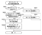
図6は、図3の制御回路によって実行されるポリゴン駆動モータ先行回転制御処理の手順を示すフローチャートである。 FIG. 6 is a flowchart showing a procedure of a polygon drive motor preceding rotation control process executed by the control circuit of FIG.
本処理は、CPU301によって実行される。
This process is executed by the
図6において、まず、現時点でポリゴン駆動モータ102が回転しているか否かを確認する(ステップS601)。すでにポリゴン駆動モータ102が回転している場合、ポリゴン駆動モータ102の回転状態はそのままとして(ステップS602)、この処理を終了する。
In FIG. 6, first, it is confirmed whether or not the
ステップS601の確認結果、ポリゴン駆動モータ102が回転していない場合、ポリゴン駆動モータ102の寿命を判定する(ステップS603)。ポリゴン駆動モータ102の寿命判定は、前述のポリゴン駆動モータ累積起動回数カウンタ305の値と起動回数寿命警戒値503とを比較することによって行われる。
As a result of the confirmation in step S601, if the
ポリゴン駆動モータ累積起動回数カウンタ305の値が起動回数寿命警戒値503を超えた値である場合、ポリゴン駆動モータ102の寿命に余裕がないと判断し、ポリゴン駆動モータ102は停止のまま速度変更を行わず(ステップS604)、この処理を終了する。
When the value of the polygon drive motor cumulative
また、ポリゴン駆動モータ累積起動回数カウンタ305の値が起動回数寿命警戒値503以下である場合は、ポリゴン駆動モータ102の先行回転動作を開始する(ステップS605)。次いで、ポリゴン駆動モータ累積起動回数カウンタ305を1カウントアップして(ステップS606)、この処理を終了する。
If the value of the polygon drive motor cumulative
なお、ポリゴン駆動モータ累積起動回数カウンタ305は、ポリゴン駆動モータ先行回転時だけではなく、ポリゴン駆動モータ停止状態からのジョブ開始時や、ポリゴン駆動モータ停止時からの自動調整のなどの場合にポリゴン駆動モータ102を起動する際にもカウントアップされる。
The polygon drive motor cumulative
また図6のポリゴン駆動モータ先行回転制御処理は、各色のポリゴン駆動モータ別に行われる。このため、故障等によってポリゴン駆動モータ102を1つだけ別時期に交換した場合や、特定の色のポリゴン駆動モータ102だけ寿命の異なるモータを使用した場合でも、正しい先行回転の判断が可能である。
Further, the polygon drive motor advance rotation control process of FIG. 6 is performed for each color polygon drive motor. For this reason, even when only one
図6の処理によれば、ポリゴン駆動モータの先行回転制御において、ポリゴン駆動モータ累積起動回数カウンタ305の値が起動回数寿命警戒値503を超えた値である場合(ステップS603でY)、ポリゴン駆動モータ102の寿命に余裕がないと判断する。そして、ポリゴン駆動モータ102は停止のままとする(ステップS604)ので、ポリゴン駆動モータ102の寿命を延ばすことができる。
According to the processing of FIG. 6, when the value of the polygon driving motor cumulative
図7は、図6のポリゴン駆動モータ先行回転制御処理にて、寿命に余裕が無いためにポリゴン駆動モータは停止のまま速度変更を行わないと判断した場合の、ポリゴン駆動モータとジョブ状態を示すタイムチャートである。 FIG. 7 shows the polygon drive motor and the job state when it is determined in the polygon drive motor advance rotation control process of FIG. 6 that the speed of the polygon drive motor is not changed because the life is not enough. It is a time chart.
おもな形態は、図4(a)に準ずるものである。(1)はポリゴン駆動モータ102の回転速度を示し、(2)はプリントジョブの動作中信号を示す。
The main form is similar to FIG. (1) indicates the rotational speed of the
操作パネル313上でキーが押下されるか、もしくは圧板219の開閉を検知した時にポリゴン先行回転トリガを発生する。この時CPU301は図6のポリゴン駆動モータ先行回転制御を実行し、ポリゴン駆動モータ102が停止のままである場合、ポリゴン駆動モータ12を停止のまま回転させない。続いて、ユーザが操作パネル313上のコピースタートボタンを押下すると、プリントジョブが開始される。この時になってから、ポリゴン駆動モータ102は回転を開始する。
When a key is pressed on the
プリントジョブが終了した後、次のジョブに備えるべくポリゴン駆動モータ102を一定時間まで、後準備回転中として回転させておく点に関しては、図6の寿命の判断結果に依らず実行する。
After the print job is completed, until a certain time the
これは、ポリゴン駆動モータ102の寿命において支配的であるのは起動回数であるため、短い間隔でユーザが原稿を交換してコピージョブを実行することを考慮した場合、ポリゴン駆動モータ102を後準備回転状態としておいたほうが寿命維持に有利であるためである。
Since the number of activations is dominant in the life of the
よって、所定時間経過してポリゴン駆動モータ102を停止するが、もしこの間にコピージョブが投入されれば、再びプリントを開始する。この場合はポリゴン駆動モータ102の起動を行う必要は無い。
Therefore, the
図8は、図3における操作パネルに示されるポリゴン駆動モータ累積起動回数カウンタをクリアするための画面を示す図である。 FIG. 8 is a diagram showing a screen for clearing the polygon drive motor cumulative activation number counter shown on the operation panel in FIG.
図8において、カウンタ表示画面801は、ポリゴン駆動モータ102の累積起動回数カウンタ表示画面であり、操作パネル313上に表示されるものである。
In FIG. 8, a
カウンタ表示画面801上には、ポリゴン駆動モータ累積起動回数カウンタ305の現在値を表示するポリゴン駆動モータ累積起動回数表示部0802と、ポリゴン駆動モータ102を寿命と判定する起動回数寿命値501を表示する累積起動回数値表示部0803とが配置される。
On the
また、カウンタ表示画面801上には、カウンタクリアボタン804と、カウンタ表示画面退出ボタン805とが配置される。
On the
ユーザ操作にてカウンタクリアボタン804が押下されると、ポリゴン駆動モータ累積起動回数カウンタ305を0に初期化する。ユーザが表示値を確認したり、カウンタクリア操作を行った後、カウンタ表示画面退出ボタン805を押すと、通常のコピー操作画面へと復帰する。カウンタクリアボタン804によるポリゴン駆動モータ累積起動回数カウンタ305のクリアは、図1のレーザスキャナユニットを交換した時に実行する。
When the counter
102 ポリゴン駆動モータ
103 ポリゴンミラー
107 感光ドラム(感光体)
301 CPU
302 ROM
303 RAM
304 バックアップRAM
305 ポリゴン駆動モータ累積起動開始カウンタ
102
301 CPU
302 ROM
303 RAM
304 Backup RAM
305 Polygon drive motor cumulative start counter
Claims (4)
前記潜像を形成するために光源から出射される光ビームが前記像担持体を走査するように前記光ビームを反射させる回転多面鏡と、
前記回転多面鏡を回転駆動するモータと、
停止状態から回転状態へ移行した回数である前記モータの起動回数をカウントするカウンタと、
前記カウンタのカウント値が所定値より少ない場合、前記画像形成開始信号が発生されるより前に、前記画像形成装置になされた所定の操作を検出したことに応じて前記モータを起動し、前記カウント値が前記所定値以上の場合、前記画像形成開始信号の発生に応じて前記モータを起動させる制御部とを備えることを特徴とする画像形成装置。 An image forming apparatus that forms a latent image on an image carrier in response to an image formation start signal,
A rotating polygon mirror that reflects the light beam so that a light beam emitted from a light source to scan the image carrier to form the latent image ;
A motor for rotationally driving the rotary polygon mirror ;
A counter that counts the number of times the motor has been started, which is the number of times that the motor has shifted from the stopped state to the rotating state
When the count value of the counter is less than a predetermined value, the motor is activated in response to detecting a predetermined operation performed on the image forming apparatus before the image formation start signal is generated , and the count An image forming apparatus comprising: a control unit that activates the motor in response to generation of the image formation start signal when the value is equal to or greater than the predetermined value.
前記潜像を形成するために光源から出射される光を反射して前記像担持体を走査する回転多面鏡を回転駆動するモータと、
前記モータの起動回数をカウントするカウンタと、
前記モータの回転状態を判定する回転判定部と、
前記回転判定部により前記モータが回転していないと判定された場合において、前記カウンタのカウント値が所定値より少ないときは前記画像形成開始信号が発生されるより前に、前記画像形成装置になされた所定の操作を検出したことに応じて前記モータを起動させる一方、前記カウンタのカウント値が前記所定値以上のときは前記画像形成開始信号が発生されるまで前記モータを起動させない制御部とを備えることを特徴とする画像形成装置。 An image forming apparatus that forms a latent image on an image carrier in response to an image formation start signal,
A motor that rotationally drives a rotary polygon mirror that reflects the light emitted from a light source to scan the image carrier to form the latent image;
A counter for counting the number of times the motor is started;
A rotation determination unit for determining a rotation state of the motor;
When the rotation determination unit determines that the motor is not rotating, if the count value of the counter is less than a predetermined value, the rotation is performed by the image forming apparatus before the image formation start signal is generated. A controller that activates the motor in response to detection of the predetermined operation, and that does not activate the motor until the image formation start signal is generated when the count value of the counter is equal to or greater than the predetermined value. An image forming apparatus comprising the image forming apparatus.
Priority Applications (2)
| Application Number | Priority Date | Filing Date | Title |
|---|---|---|---|
| JP2006162573A JP4928170B2 (en) | 2006-06-12 | 2006-06-12 | Image forming apparatus |
| US11/761,352 US7952604B2 (en) | 2006-06-12 | 2007-06-11 | Image forming apparatus |
Applications Claiming Priority (1)
| Application Number | Priority Date | Filing Date | Title |
|---|---|---|---|
| JP2006162573A JP4928170B2 (en) | 2006-06-12 | 2006-06-12 | Image forming apparatus |
Publications (3)
| Publication Number | Publication Date |
|---|---|
| JP2007333803A JP2007333803A (en) | 2007-12-27 |
| JP2007333803A5 JP2007333803A5 (en) | 2011-05-06 |
| JP4928170B2 true JP4928170B2 (en) | 2012-05-09 |
Family
ID=38821633
Family Applications (1)
| Application Number | Title | Priority Date | Filing Date |
|---|---|---|---|
| JP2006162573A Expired - Fee Related JP4928170B2 (en) | 2006-06-12 | 2006-06-12 | Image forming apparatus |
Country Status (2)
| Country | Link |
|---|---|
| US (1) | US7952604B2 (en) |
| JP (1) | JP4928170B2 (en) |
Cited By (1)
| Publication number | Priority date | Publication date | Assignee | Title |
|---|---|---|---|---|
| US9130572B2 (en) | 2011-08-30 | 2015-09-08 | Yamaha Corporation | Controller provided with touch detection device including movable and fixed contact patterns |
Families Citing this family (4)
| Publication number | Priority date | Publication date | Assignee | Title |
|---|---|---|---|---|
| JP5355174B2 (en) * | 2009-03-27 | 2013-11-27 | キヤノン株式会社 | Image forming apparatus |
| JP5429690B2 (en) * | 2009-09-14 | 2014-02-26 | 株式会社リコー | Image forming apparatus and power consumption notification method |
| JP5696773B2 (en) * | 2013-12-11 | 2015-04-08 | 株式会社リコー | Image forming apparatus |
| JP6642202B2 (en) * | 2016-03-30 | 2020-02-05 | ブラザー工業株式会社 | Image forming apparatus, control method thereof, and program |
Family Cites Families (10)
| Publication number | Priority date | Publication date | Assignee | Title |
|---|---|---|---|---|
| JPS63124786A (en) * | 1986-11-14 | 1988-05-28 | Canon Inc | Controller for motor |
| JPH05188311A (en) * | 1991-02-26 | 1993-07-30 | Ricoh Co Ltd | Recorder |
| JPH07273951A (en) | 1994-03-30 | 1995-10-20 | Toshiba Corp | Image forming device |
| JP3501502B2 (en) * | 1994-06-10 | 2004-03-02 | キヤノン株式会社 | Image forming device |
| JPH11202717A (en) * | 1998-01-13 | 1999-07-30 | Toshiba Corp | Device and method for forming image |
| JP2000203082A (en) * | 1999-01-13 | 2000-07-25 | Ricoh Co Ltd | Image forming apparatus |
| JP2002131681A (en) * | 2000-10-25 | 2002-05-09 | Canon Inc | Image forming device provided with statistical function |
| JP2002174790A (en) * | 2000-12-06 | 2002-06-21 | Toshiba Tec Corp | Image forming device |
| JP2005225157A (en) * | 2004-02-16 | 2005-08-25 | Konica Minolta Business Technologies Inc | Image forming apparatus |
| JP4259344B2 (en) * | 2004-02-18 | 2009-04-30 | コニカミノルタビジネステクノロジーズ株式会社 | Image forming apparatus |
-
2006
- 2006-06-12 JP JP2006162573A patent/JP4928170B2/en not_active Expired - Fee Related
-
2007
- 2007-06-11 US US11/761,352 patent/US7952604B2/en not_active Expired - Fee Related
Cited By (1)
| Publication number | Priority date | Publication date | Assignee | Title |
|---|---|---|---|---|
| US9130572B2 (en) | 2011-08-30 | 2015-09-08 | Yamaha Corporation | Controller provided with touch detection device including movable and fixed contact patterns |
Also Published As
| Publication number | Publication date |
|---|---|
| US20070285738A1 (en) | 2007-12-13 |
| US7952604B2 (en) | 2011-05-31 |
| JP2007333803A (en) | 2007-12-27 |
Similar Documents
| Publication | Publication Date | Title |
|---|---|---|
| JP5235475B2 (en) | Image forming apparatus | |
| JP4928170B2 (en) | Image forming apparatus | |
| JP2003280452A (en) | Image forming apparatus | |
| JP4698303B2 (en) | Image forming apparatus | |
| US7787166B2 (en) | Method for controlling image forming apparatus | |
| JP2015187723A (en) | image forming apparatus | |
| JP2007310365A (en) | Method for controlling image forming apparatus | |
| JP5624968B2 (en) | Image forming apparatus | |
| JP2010256477A (en) | Color image forming apparatus | |
| US20070216758A1 (en) | Driving control device, image forming apparatus and recording medium for recording driving control program | |
| JP2011059325A (en) | Image forming apparatus and method for controlling the same | |
| JP5380513B2 (en) | Image forming apparatus | |
| JP5257042B2 (en) | Image forming method and apparatus | |
| JP2020059235A (en) | Image processing device, abnormal member detection method and abnormal member detection program | |
| JP5478970B2 (en) | Image forming apparatus | |
| JP5361146B2 (en) | Image forming apparatus and control method thereof | |
| JP2009300864A (en) | Image forming apparatus | |
| JPH10319652A (en) | Image forming device | |
| JP2007108361A (en) | Image forming apparatus | |
| JPH11119478A (en) | Image forming device | |
| JP2005164922A (en) | Image forming apparatus | |
| JP2020061686A (en) | Image processing apparatus, abnormal member detection method, and abnormal member detection program | |
| JP4280534B2 (en) | Image forming apparatus | |
| JP2024069073A (en) | Image formation apparatus | |
| JP2003341133A (en) | Imaging apparatus |
Legal Events
| Date | Code | Title | Description |
|---|---|---|---|
| A521 | Written amendment |
Free format text: JAPANESE INTERMEDIATE CODE: A523 Effective date: 20090420 |
|
| A621 | Written request for application examination |
Free format text: JAPANESE INTERMEDIATE CODE: A621 Effective date: 20090420 |
|
| A521 | Written amendment |
Free format text: JAPANESE INTERMEDIATE CODE: A523 Effective date: 20110318 |
|
| A131 | Notification of reasons for refusal |
Free format text: JAPANESE INTERMEDIATE CODE: A131 Effective date: 20110822 |
|
| A521 | Written amendment |
Free format text: JAPANESE INTERMEDIATE CODE: A523 Effective date: 20111018 |
|
| TRDD | Decision of grant or rejection written | ||
| A01 | Written decision to grant a patent or to grant a registration (utility model) |
Free format text: JAPANESE INTERMEDIATE CODE: A01 Effective date: 20120207 |
|
| A01 | Written decision to grant a patent or to grant a registration (utility model) |
Free format text: JAPANESE INTERMEDIATE CODE: A01 |
|
| A61 | First payment of annual fees (during grant procedure) |
Free format text: JAPANESE INTERMEDIATE CODE: A61 Effective date: 20120210 |
|
| FPAY | Renewal fee payment (event date is renewal date of database) |
Free format text: PAYMENT UNTIL: 20150217 Year of fee payment: 3 |
|
| R151 | Written notification of patent or utility model registration |
Ref document number: 4928170 Country of ref document: JP Free format text: JAPANESE INTERMEDIATE CODE: R151 |
|
| FPAY | Renewal fee payment (event date is renewal date of database) |
Free format text: PAYMENT UNTIL: 20150217 Year of fee payment: 3 |
|
| LAPS | Cancellation because of no payment of annual fees |