JP4923820B2 - Functional material coating apparatus and functional material coating method - Google Patents
Functional material coating apparatus and functional material coating method Download PDFInfo
- Publication number
- JP4923820B2 JP4923820B2 JP2006203255A JP2006203255A JP4923820B2 JP 4923820 B2 JP4923820 B2 JP 4923820B2 JP 2006203255 A JP2006203255 A JP 2006203255A JP 2006203255 A JP2006203255 A JP 2006203255A JP 4923820 B2 JP4923820 B2 JP 4923820B2
- Authority
- JP
- Japan
- Prior art keywords
- coating liquid
- coating
- functional material
- discharge
- coated
- Prior art date
- Legal status (The legal status is an assumption and is not a legal conclusion. Google has not performed a legal analysis and makes no representation as to the accuracy of the status listed.)
- Expired - Fee Related
Links
Images


Description
本発明は、例えば、電子材料、光学材料など機能性材料を所望の被塗布物に塗布するための機能性材料塗布液、及び機能性材料塗布方法に関する。 The present invention relates to a functional material coating liquid and a functional material coating method for coating a functional material such as an electronic material and an optical material on a desired object.
従来、コピー機、プリンターに搭載される感光性ドラムなど電子写真感光体は、主として浸漬塗布法により製造されてきた。この方法では、材料の性能管理のため、実際に塗布されるよりも相当多くの量を要求されるため、無駄が多かった。また、浸漬速度や乾燥速度の精密な管理が必要とされるため、環境変動などにより、バラツキが発生し、不良品となる割合が高かった。 Conventionally, an electrophotographic photosensitive member such as a photosensitive drum mounted on a copying machine or a printer has been mainly manufactured by a dip coating method. In this method, a considerably larger amount than that actually applied is required for performance management of the material, which is wasteful. In addition, since precise control of the dipping rate and drying rate is required, there was a high percentage of defective products due to variations due to environmental fluctuations.
一方、近年、インクジェット技術の工業用途への適用の検討が盛んである。家庭でのカラープリントや写真の印刷にインクジェットは広く、いきわたっているが、印刷対象を用紙ではなく、また塗布液をインクではなく工業用材料とすることの例が発表されている。 On the other hand, in recent years, studies on application of inkjet technology to industrial applications are actively conducted. Inkjet is widely used for color printing and photo printing at home, but there are examples of printing not on paper but on coating liquids as industrial materials instead of ink.
例えば、特許文献1〜4には、このようなインクジェット技術を用いて、高分子膜や導電性膜などの機能膜を形成し、電子写真部材などの工業製品を製造することが提案されている。 For example, Patent Documents 1 to 4 propose using such an ink jet technique to form a functional film such as a polymer film or a conductive film to manufacture an industrial product such as an electrophotographic member. .
ところが、インクジェット方式を成膜などの塗布技術として使用すると、液滴の速度の適正値として、マーキングとは異なる課題があることが判った。マーキングでは、液滴の体積のばらつきと液滴の着弾位置のばらつきを少なくするため、外乱の影響を受けにくい吐出安定性の得られる比較的速い液滴吐出速度を採用している。しかし、その液滴吐出速度を成膜などの塗布技術として使用すると、以下のような問題が発生した。 However, when the inkjet method is used as a coating technique such as film formation, it has been found that there is a problem different from marking as an appropriate value of the droplet velocity. In the marking, in order to reduce variations in droplet volume and droplet landing position, a relatively fast droplet ejection speed is employed that provides ejection stability that is less susceptible to disturbance. However, when the droplet discharge speed is used as a coating technique such as film formation, the following problems occur.
1)紙への印字とは異なり、被塗布物が金属やプラスチックあるいはセラミックスのような硬いものであるため、液滴の跳ね返りが大きく塗布膜の厚みがばらつく原因となる。 1) Unlike printing on paper, the object to be coated is a hard material such as metal, plastic, or ceramics, so that the droplets rebound greatly, causing the coating film thickness to vary.
そこで、本発明は、上記問題に鑑み、被塗布物との着弾面において、吐出安定性を維持しつつ、塗布膜の厚みばらつきを少なくすることが可能な機能性材料塗布装置及び機能性材料塗布方法を提供することを目的とする。 Therefore, in view of the above problems, the present invention provides a functional material coating apparatus and a functional material coating capable of reducing variation in the thickness of a coating film while maintaining ejection stability on a landing surface with an object to be coated. It aims to provide a method.
上記課題は、以下の手段により解決される。即ち、
本発明の機能性材料塗布装置は、機能性材料の塗布液を被塗布物へ吐出する塗布液吐出ヘッドと、少なくとも前記塗布液吐出ヘッドから前記塗布液を吐出する時、前記塗布液吐出ヘッドから遠ざかるように前記被塗布物における前記塗布液の着弾面を移動する着弾面移動手段と、を有し、
前記塗布液が前記塗布液吐出ヘッドから吐出した直後における吐出方向に沿った前記塗布液の吐出速度よりも、前記塗布液が前記被塗布物へ着弾したときにおける当該着弾した面の法線方向に沿った前記塗布液の着弾速度が遅い、
ことを特徴としている。
The above problem is solved by the following means. That is,
The functional material coating apparatus according to the present invention includes a coating liquid ejection head that ejects a coating liquid of a functional material onto an object to be coated, and at least when the coating liquid is ejected from the coating liquid ejection head, A landing surface moving means for moving the landing surface of the coating liquid in the coating object so as to be away from the object ,
The normal direction of the landed surface when the coating liquid lands on the object to be coated, rather than the discharge speed of the coating liquid along the discharge direction immediately after the coating liquid is discharged from the coating liquid discharge head. The landing speed of the coating liquid along is slow,
It is characterized by that.
本発明の機能性材料塗布装置では、吐出直後の塗布液の吐出速度よりも、被塗布物の着弾面における法線方向に沿った塗布液の着弾速度を遅くするようにすることで、吐出安定性を維持しつつ、着弾した塗布液の跳ね返りが低減でき、形成される塗布膜の不均一性防止や例えば着弾面が他の塗布膜で構成された場合でも当該他の塗布膜を乱すことが抑制される。 In the functional material coating apparatus of the present invention, the ejection speed of the coating liquid along the normal direction on the landing surface of the coating object is made slower than the ejection speed of the coating liquid immediately after ejection, thereby stabilizing the ejection. The rebound of the landed coating liquid can be reduced while maintaining the properties, and the nonuniformity of the formed coating film can be prevented, for example, even when the landing surface is composed of another coating film, the other coating film can be disturbed. It is suppressed.
本発明の機能性材料塗布装置において、被塗布物の着弾面における法線方向に沿った塗布液の着弾速度を遅くする形態としては、以下のような形態が挙げられる。 In the functional material coating apparatus of the present invention, examples of the form in which the landing speed of the coating liquid along the normal direction on the landing surface of the object to be coated are slow include the following forms.
・前記塗布液が前記被塗布物へ着弾する着弾面の法線方向と前記塗布液の吐出方向とが角度をなして、前記塗布液が被塗布物へ着弾するように、前記塗布液吐出ヘッドを配置する形態。 The coating liquid discharge head so that the normal direction of the landing surface on which the coating liquid lands on the object to be coated and the discharge direction of the coating liquid form an angle so that the coating liquid lands on the object to be coated. Form to arrange.
・水平方向よりも上方側に向かって前記塗布液が被塗布物へ吐出するように、前記塗布液吐出ヘッドを配置する形態。 A form in which the coating liquid discharge head is arranged so that the coating liquid is discharged onto the object to be coated upward from the horizontal direction.
・前記塗布液吐出ヘッドから吐出された前記塗布液の吐出速度を低減する吐出速度低減手段をさらに有する形態。この形態の場合、前記吐出速度低減手段は、吐出された前記塗布液に電界を付与する電界付与手段であることが好適である。 A mode that further includes a discharge speed reduction unit that reduces a discharge speed of the coating liquid discharged from the coating liquid discharge head. In the case of this form, it is preferable that the discharge speed reducing means is an electric field applying means for applying an electric field to the discharged coating liquid.
一方、本発明の機能性材料塗布方法は、機能性材料の塗布液を被塗布物へ吐出する機能性材料塗布方法であって、
前記塗布液が前記塗布液吐出ヘッドから吐出した直後における吐出方向に沿った前記塗布液の吐出速度よりも、前記塗布液が前記被塗布物へ着弾したときにおける当該着弾した面の法線方向に沿った前記塗布液の着弾速度を遅くし、
少なくとも前記塗布液吐出ヘッドから前記塗布液を吐出する時、前記塗布液吐出ヘッドから遠ざかるように前記被塗布物における前記塗布液の着弾面を移動させる、
ことを特徴としている。
On the other hand, the functional material coating method of the present invention is a functional material coating method for discharging a functional material coating liquid onto an object to be coated,
The normal direction of the landed surface when the coating liquid lands on the object to be coated, rather than the discharge speed of the coating liquid along the discharge direction immediately after the coating liquid is discharged from the coating liquid discharge head. Slow down the landing speed of the coating liquid along ,
When discharging at least the coating liquid from the coating liquid discharge head, Ru said moving the landing surface of the coating liquid in the coating object away from the coating liquid discharge head,
It is characterized by that.
本発明の機能性材料塗布方法では、上記本発明の機能性材料装置と同様に、吐出直後の塗布液の吐出速度よりも、被塗布物の着弾面における法線方向に沿った塗布液の着弾速度を遅くするようにすることで、着弾した塗布液の跳ね返りが低減でき、形成される塗布膜の不均一性防止や例えば着弾面が他の塗布膜で構成された場合でも当該他の塗布膜を乱すことが抑制される。 In the functional material coating method of the present invention, as with the functional material device of the present invention described above, the landing of the coating liquid along the normal direction on the landing surface of the object to be coated is faster than the discharging speed of the coating liquid immediately after discharging. By reducing the speed, the splashing of the landing coating liquid can be reduced, and the nonuniformity of the formed coating film can be prevented, for example, even when the landing surface is composed of another coating film. Disturbing is suppressed.
本発明の機能性材料塗布方法において、被塗布物の着弾面における法線方向に沿った塗布液の着弾速度を遅くする形態としては、以下のような形態が挙げられる。 In the functional material coating method of the present invention, examples of the form in which the landing speed of the coating solution along the normal direction on the landing surface of the object to be coated are slow include the following forms.
・前記塗布液が前記被塗布物へ着弾する着弾面の法線方向と前記塗布液の吐出方向とが角度をなして、前記塗布液が被塗布物へ着弾するように、前記塗布液を被塗布物へ吐出する形態。 The normal direction of the landing surface on which the coating liquid lands on the object to be coated and the discharge direction of the coating liquid make an angle so that the coating liquid lands on the object to be coated. A form to be discharged onto the coating.
・水平方向よりも上方側に向かって、前記塗布液を被塗布物へ吐出する形態。 A form in which the coating liquid is discharged onto the object to be coated upward from the horizontal direction.
・前記塗布液吐出ヘッドから吐出された前記塗布液の吐出速度を低減する形態。この形態の場合、前記塗布液吐出ヘッドから吐出された前記塗布液の吐出速度を電界により低減することが好ましい。 A mode in which the discharge speed of the coating liquid discharged from the coating liquid discharge head is reduced. In the case of this embodiment, it is preferable that the discharge speed of the coating liquid discharged from the coating liquid discharge head is reduced by an electric field.
・少なくとも前記塗布液吐出ヘッドから前記塗布液を吐出する時、前記塗布液吐出ヘッドから遠ざかるように前記被塗布物における前記塗布液の着弾面を移動する形態。 A mode in which the landing surface of the coating liquid on the coating object is moved away from the coating liquid discharging head when discharging the coating liquid from at least the coating liquid discharging head.
本発明によれば、被塗布物との着弾面において、吐出安定性を維持しつつ、塗布膜の厚みばらつきを少なくすることが可能な機能性材料塗布装置及び機能性材料塗布方法を提供することができる。 According to the present invention, there are provided a functional material coating apparatus and a functional material coating method capable of reducing variation in the thickness of a coating film while maintaining ejection stability on a landing surface with an object to be coated. Can do.
以下、本発明について図面を参照しつつ詳細に説明する。なお、実質的に同一の機能を有する部材には、全図面を通して同じ符合を付与し、重複する説明は省略する場合がある。 Hereinafter, the present invention will be described in detail with reference to the drawings. In addition, the same code | symbol is provided to the member which has the substantially same function through all the drawings, and the overlapping description may be abbreviate | omitted.
(第1実施形態)
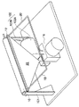
図1は、第1実施形態に係る機能性材料塗布装置を示す斜視図である。図2は、第1実施形態に係る機能性材料塗布装置を示す概略構成図である。
(First embodiment)
FIG. 1 is a perspective view showing a functional material coating apparatus according to the first embodiment. FIG. 2 is a schematic configuration diagram illustrating the functional material coating apparatus according to the first embodiment.
第1実施形態に係る機能性材料塗布装置は、図1〜図2に示すように、機能性材料の塗布液14を被塗布物10へ吐出するための吐出ヘッド12と、当該吐出ヘッド12へ送液する塗布液14を貯留する塗布液タンク16と、を有している。
As shown in FIGS. 1 to 2, the functional material coating apparatus according to the first embodiment includes a
そして、吐出ヘッド12は、吐出する塗布液14が被塗布物10へ着弾する着弾面の法線方向(図中、qで示す)と塗布液の吐出方向(図中、pで示す)とが角度(鋭角:θ)をなして、塗布液14の液滴が被塗布物10へ着弾するように配置している。なお、着弾面の法線とは、被塗布物の着弾面が平面で構成される場合(例えば被塗布物が板状体の場合)は、その面と直交する線を示し、本実施形態のように被塗布物の着弾面が曲面で構成される場合(例えば被塗布物が球体或いは円筒体などの場合)には、その着弾した位置の接線(図中、rで示す)で構成される面と直交する線を示す。
The
吐出ヘッド12には、塗布液吐出面側(ノズル面)側に、吐出した塗布液14を帯電させる帯電電極24と、その帯電した塗布液14に電界を付与し偏向を与え吐出方向を変える偏向電極26と、が配設されている。なお、このような帯電・偏向制御は、塗布量を制限したり、塗布にパターンを持たせる場合に行うことが好適である。このようなことが必要なければ、帯電電極24及び偏向電極26を設けなくてもよい。
The
また、吐出ヘッド12の一端には、塗布液供給管18が連結され、他端には、塗布液排出管20が連結されている。塗布液供給管18及び塗布液排出管20の一端側(吐出ヘッド12と非連結側)は、塗布液タンク16と連結されている。そして、塗布液供給管18には、塗布液タンク側から吐出ヘッド12に向かって、送液用ポンプ181(加圧手段:溶剤用高圧無動脈ポンプ:3連プランジャポンプ)、送液用ポンプ181の脈動を抑制するダンパ182、塗布液のゴミ異物等を除去するフィルタ183、吐出ヘッド12への塗布液14の送液を開始・停止を行うための送液用電磁弁184が配設されている。一方、塗布液排出管20には、塗布液14の排出を開始・停止する排出用電磁弁201が配設されている。
A coating
なお、排出用電磁弁201は、通常、常に閉状態とし、塗布液14の循環、混入した気泡の除去などを行う際に開放するものである。
The
被塗布物10は、円筒体から構成されており、その両端を回転可能に支持体101により支持されている。また、被塗布物10は、被塗布物駆動装置102により回転可能に、具体的には駆動モータ102Aによりベルト102Bを介して回転駆動可能に連結されている。
The object to be coated 10 is composed of a cylindrical body, and both ends thereof are supported by a
吐出ヘッド12と被塗布物10との間であって、吐出した塗布液14の液滴を下方へ帯電・偏向制御したときに当該塗布液14を受け止められる位置(塗布液14吐出方向の延長線より下方に上端が配置される位置)に液受け22(吐出塗布液回収手段)が設けられている。液受け22は、塗布液タンク16とフィルタ223を介して排出管222により連結されており、吐出した塗布液14を受け止めた時、当該塗布液タンク16へ排出するようになっている。
A position between the
以下、吐出ヘッド12について説明する。ここで、図3は、第1実施形態に係る塗布液吐出ヘッドを示す斜視図である。図4は、第1実施形態に係る塗布液吐出ヘッドの断面図である。
Hereinafter, the
吐出ヘッド12は、図3〜図4に示すように、例えば、ステンレスやニッケル合金などからなる筒状体で構成されている。そして、吐出ヘッド12には、長手方向に配列された複数のノズル121(例えば、ノズル内径25μm)と、各ノズル121に共通して連通する塗布液室122と、塗布液室122を介してノズル121と対向して設けられた圧電素子123(例えばPZTセラミック膜、ポリフッ化ビニリデン膜(PVF2膜))と、を有している。
As shown in FIGS. 3 to 4, the
なお、吐出ヘッド12は、塗布時、図示しない駆動装置によりヘッド長手方向に配列されたノズル間隔分、当該ヘッド長手方向に往復して移動するようになっている。これにより、ノズル間隔分の隙間が生じることなく被塗布物10に塗布液14を塗布することができる。無論、被塗布物10の方を移動可能なようにしてもよい。
The
ここで、圧電素子123は、塗布液室122に送液されてきた塗布液14に対し、所定の振動を付与し、ノズル121から液柱状に吐出した塗布液14を液滴化するためのものである。圧電素子123は、図示しないが、例えばPZTセラミック膜に電極から高周波電圧を印加して振動(音波)を発生せしめ、この振動をピストンにより塗布液室122の塗布液14へ伝達せしめる。
Here, the
圧電素子123は、ノズル121と対向して設けられ、塗布液14の吐出方向と同一方向から、図示しない外部機器より増幅され例えばピーク間電圧(Vpp)50V程度までの電圧で出力する駆動正弦波が供給されると、定在波(進行波と反射波との混合した波:つまり、照射した進行波とノズル面に反射した反射波との混合波)による振動を付与して、ノズル121から液柱状に吐出した塗布液14を液滴化する。
The
ここで、図5〜図7に、粘度約9mPa・s程度の塗布液14の吐出状態を示す。図5は、振動を付与しない場合における塗布液14の吐出状態を示す模式図である。図6は、90kHzの振動を付与した場合における塗布液14の吐出状態を示す模式図である。図7は、60kHzの振動を付与した場合における塗布液14の吐出状態を示す模式図である。
Here, the discharge state of the
圧電素子123を駆動させず、例えば、送液用ポンプ181により0.9MPaで吐出ヘッド12から塗布液14を吐出した場合、図5に示すように、液柱状の塗布液14が吐出する。そして、圧電素子123により塗布液14に振動を付与すると、図6及び図7に示すように、液柱状に吐出された塗布液14が液滴化される。図6、7に示するように、90kHzの振動を塗布液14に付与した場合は、60kHz振動を塗布液14に付与したに場合に比べ、塗布液の液滴径が小さく、液滴間距離(液滴間隔)が狭くなっている。しかし、ポンプ圧力は一定であるので、単位時間あたりの噴射量は同一である。
For example, when the
図5に示すように、液滴化せず、液柱状の状態で塗布液を塗布すると、吐出ヘッド12から離れた位置では、無秩序な噴流となるため、塗布膜の均一性が確保できない。よって、塗布液14の液滴化が必要である。
As shown in FIG. 5, when the coating liquid is applied in a liquid column state without forming droplets, a disordered jet is formed at a position away from the
ここで、例えば、塗布液の吐出速度10m/sec、ノズル内径25μmとしたとき、好適周波数は、88.7kHzとなる。また、液滴の体積は、約55pl(pico litre)(55,000μm3)である。但し、液滴化の観点のみで、周波数は決定されず、吐出ヘッドと圧電素子の振動特性を考慮する必要がある。即ち、吐出ヘッドの構造と圧電素子の特性に基づく共振点を考慮することで、圧電素子に印加する電圧の調整を行なう必要がある。例えば、本実施形態では、ピーク間電圧(Vpp)30V程度の電圧を圧電素子に印加する。 Here, for example, when the discharge speed of the coating liquid is 10 m / sec and the nozzle inner diameter is 25 μm, the preferred frequency is 88.7 kHz. The volume of the droplet is about 55 pl (pico liter) (55,000 μm 3 ). However, the frequency is not determined only from the viewpoint of droplet formation, and it is necessary to consider the vibration characteristics of the ejection head and the piezoelectric element. That is, it is necessary to adjust the voltage applied to the piezoelectric element by considering the resonance point based on the structure of the ejection head and the characteristics of the piezoelectric element. For example, in the present embodiment, a voltage having a peak-to-peak voltage (Vpp) of about 30 V is applied to the piezoelectric element.
また、粘度約9mPa・s程度の塗布液14を10m/secで吐出するための圧力は例えば約0.9MPaであるが、粘度3mPa・s程度の塗布液を吐出する場合は、例えば0.3MPa程度の圧力を必要とすることが実験によりわかった。したがって、粘度100mPa・s程度の塗布液を吐出するためには、例えば10MPa程度の圧力が必要であると予想される。これは、塗布液に掛かる圧力と流速が流路抵抗を係数とする1次の関係にあることより説明される。ただし、上記の数値は一例である。
The pressure for discharging the
それは、ノズルの形状により抵抗値が大きく変わるからである。ノズル加工方法には、一般的にポンチ加工方法、エレクトロフォーミング(電鋳)加工方法、放電加工方法、レーザ加工方法などが挙げられる。それぞれの加工方法には得失があり、一概にどの方法が好ましいか決定することはできないが、ノズル内径を一定にして比較した場合、ノズルにおける流路抵抗の観点からは、ノズルの断面形状に大きなテーパを有するエレクトロフォーミング(電鋳)が極力、噴射の圧力を低く保つという観点では好ましい。 This is because the resistance value varies greatly depending on the shape of the nozzle. Examples of the nozzle machining method generally include a punch machining method, an electroforming (electroforming) machining method, an electric discharge machining method, and a laser machining method. There are advantages and disadvantages to each processing method, and it is not possible to generally decide which method is preferable. However, when compared with a constant nozzle inner diameter, the cross-sectional shape of the nozzle is large from the viewpoint of the flow resistance of the nozzle. Tape forming electroforming is preferable from the viewpoint of keeping the injection pressure as low as possible.
以下、本実施形態に係る機能性材料塗布装置の塗布動作を説明する。 Hereinafter, the coating operation of the functional material coating apparatus according to the present embodiment will be described.
まず、送液用ポンプ181を駆動すると共に、送液用電磁弁184を開放する。また、圧電素子123を駆動する。これにより、ノズル121から液柱状の塗布液14が吐出すると共に、液柱状の塗布液14が液滴化される。この際、帯電電極24に所定の電圧を印加し、吐出した塗布液14を帯電させると共に、偏向電極26にも所定の電圧を印加して、その帯電した塗布液14に電界を付与して、液受け22が位置する下方(図中)に偏向を与え、吐出方向を変えて当該液受け22に塗布液14を受け止めさせる。
First, the
次に、被塗布物駆動装置102を駆動し、被塗布物10を回転駆動する(例えば、被塗布物10の回転速度を1回転/1秒(1rps)とする)。
Next, the coating
次に、帯電電極24及び偏向電極26への電圧印加を解除して、吐出方向を戻す。これにより、塗布液14の被塗布物10への塗布が開始される。
Next, the voltage application to the charging
そして、所定時間経過後、再び、帯電電極24に所定の電圧を印加し、吐出した塗布液14を帯電させると共に、偏向電極にも所定の電圧を印加して、その帯電した塗布液14に電界を付与して、液受け22が位置する下方(図中)に偏向を与え、吐出方向を変えて当該液受け22に塗布液14を受け止めさせる。これにより、塗布を終了させる。
Then, after a predetermined time has elapsed, a predetermined voltage is applied again to the charging
その後、送液用ポンプ181の駆動を停止すると共に、送液用電磁弁184を閉じる。また、圧電素子123の駆動を停止する。最後に、被塗布物10の回転を停止する。
Thereafter, the driving of the
なお、塗布終了後、被塗布物の回転を所定時間継続することで、塗布膜の平滑化に加え、塗布膜の液だれ防止を図ることができる。塗布液14の被塗布物10表面への着弾は必ずしも全面にわたるものではなく、着弾した液滴間には隙間が存在する。また、ジェットはノズル加工の精度に起因する僅かな曲がりを有する場合がある。このため、塗布液14は被塗布物10表面に着弾後、当初、粘度が高いほど、液滴の形状を反映して半球に近い形状で存在する。このため、均一な塗布膜を形成するためには、塗布終了後、被塗布物を回転させる、即ち平滑化工程における時間管理が重要である。また、被塗布物10を回転させながら塗布膜の平滑化を行うと、その遠心力により、塗布液14が被塗布物10に対して凸状の形状を守る方向に働くため、回転速度を液だれを起こさない程度に低下させることが、好ましい。被塗布物10表面との親和性により塗布液14は広がり、被塗布物10の回転時間と共に隣接着弾滴と引き合いながら、塗布膜は平坦化していくことになる。
In addition, by continuing the rotation of the coating object for a predetermined time after the coating is completed, it is possible to prevent the coating film from dripping in addition to smoothing the coating film. The landing of the
以上説明した本実施形態に係る機能性材料塗布装置では、吐出する塗布液14が被塗布物10へ着弾する着弾面の法線方向と塗布液14の吐出方向とが角度をなして、塗布液14が被塗布物10へ着弾するように、吐出ヘッド12を配置しているので、吐出直後の塗布液14の吐出速度(吐出方向に沿った吐出速度)よりも、被塗布物10の着弾面における法線方向に沿った塗布液14の着弾速度を遅くなる。つまり、吐出安定性を維持可能な吐出速度を持たせつつ、着弾速度が、着弾面の法線方向と着弾面と平行な方向に分散するため、塗布液の着弾衝撃が緩和されると推測される。
In the functional material coating apparatus according to the present embodiment described above, the normal direction of the landing surface on which the
ここで、図8及び図9に、塗布液14の液滴の着弾モデルを模式的に示す。図8は、比較のために、着弾面(図中では、被塗布物10としての液体層の面を示す)に対し、当該面の法線方向から塗布液14の液滴が着弾する様子を示す。一方、図9には、着弾面(図中では、被塗布物10としての液体層の面を示す)に対し、当該面の法線方向と角度を持って塗布液14の液滴が着弾する様子を示す。
Here, FIGS. 8 and 9 schematically show the landing model of the droplet of the
図8に示すように、着弾面の法線方向から着弾面(液面)に速い速度で打ち込むと、跳ね返りが舞い飛ぶ。また、液面が大きく凹み、液体層の中に気泡を巻き込み、そのまま硬化すると気泡が膜内に閉じ込められてしまう。また、多層膜の場合は、下の層と混濁してしまう。一方、図9に示すように、着弾面に対し、当該面の法線方向と角度を持って塗布液14の液滴が着弾すると、着弾面の法線方向に沿った着弾速度が低減するので、跳ね返りが発生しない。
As shown in FIG. 8, when the robot is driven at a high speed from the normal direction of the landing surface to the landing surface (liquid surface), the rebound will fly. Further, when the liquid surface is greatly dented, bubbles are entrained in the liquid layer and cured as it is, the bubbles are trapped in the film. In the case of a multilayer film, it becomes turbid with the lower layer. On the other hand, as shown in FIG. 9, when the droplet of the
このように、吐出する塗布液14が被塗布物10へ着弾する着弾面の法線方向と塗布液14の吐出方向とが角度をなして、塗布液14が被塗布物10へ着弾するように、吐出ヘッド12を配置することで、吐出安定性を維持しつつ、着弾した塗布液14の跳ね返りが低減でき、形成される塗布膜の不均一性防止や例えば着弾面が他の塗布膜で構成された場合でも当該他の塗布膜を乱すことが抑制される。
In this way, the normal direction of the landing surface on which the
また、本実施形態に係る機能性材料塗布装置では、被塗布物10を回転させつつ、吐出する塗布液14が被塗布物10へ着弾する着弾面の法線方向と塗布液14の吐出方向とが角度をなして、塗布液14が被塗布物10へ着弾しているので、塗布液が着弾した際、着弾面と平行な方向、即ち、着弾面(点)の接線方向に沿った着弾速度における着弾面との相対速度(以下、接線方向相対速度と称する場合がある)が低減し、当該接線方向の塗布液の着弾衝撃が緩和される。このため、より効果的に、着弾した塗布液14の跳ね返りが低減でき、形成される塗布膜の不均一性防止や例えば着弾面が他の塗布膜で構成された場合でも当該他の塗布膜を乱すことが抑制される。
In the functional material coating apparatus according to this embodiment, the normal direction of the landing surface on which the
ここで、着弾した塗布液14の跳ね返りをより効果的に低減するためには、以下の特性を満たすことが好ましい。
Here, in order to reduce the rebound of the
塗布液14の粘度が10mPa・s以上30mPa・s以下であって、吐出する塗布液14の吐出速度(ヘッドから吐出した直後の吐出速度)が、8m/s以上12m/s以下であり、かつ、吐出する塗布液14が被塗布物10へ着弾する着弾面の法線方向と塗布液の吐出方向とが角度(鋭角:θ)としては、30度以上45度以下であることが好ましい。なお、ヘッドから吐出した直後の吐出速度とは、ノズルオリフィスを通過する塗布液の平均速度であり、単位時間にノズルオリフィス面を通過する塗布液の体積をオリフィスの断面積で割ったものである。
The viscosity of the
以下、上記第1実施形態に係る機能性材料塗布装置の試験例を示す。 Hereinafter, test examples of the functional material coating apparatus according to the first embodiment will be described.
−試験例1−1−
試験例1−1は、下記表1に記載した条件に従って行った。なお、吐出ヘッド12から吐出する塗布液14が被塗布物10へ着弾する着弾面の法線方向と塗布液14の吐出方向とがなす角度(鋭角:θ)は、図10に示すように、吐出ヘッド12から吐出する塗布液14の吐出方向を水平に保ちつつ変わるように吐出ヘッド12配置位置を変えて行った。また、被塗布物10(円筒体:外径100mm)は回転駆動させずに試験を行った。なお、評価方法は以下の通りである。
-Test Example 1-1
Test Example 1-1 was performed according to the conditions described in Table 1 below. The angle (acute angle: θ) formed by the normal direction of the landing surface on which the
ここで、図10は、第1実施形態に係る機能性塗布装置を示す概略側面図である。但し、図中、吐出ヘッド、被塗布物以外の構成は省略して示している。 Here, FIG. 10 is a schematic side view showing the functional coating apparatus according to the first embodiment. However, in the drawing, configurations other than the ejection head and the object to be coated are omitted.
・吐出安定性:ストロボ同期の吐出液観察システムで、吐出された塗布液の液滴を観察し、その液滴写真像の面積や吐出速度の繰り返し安定性を測定した。
この吐出液観察システム30は、図13に示すように、吐出ヘッド12と、吐出ヘッド12のノズル出口から500μm(Δxμm)離れた地点の塗布液14の液滴を観察するカメラ31と、カメラ31と塗布液14の液滴を介して対向配置されたストロボ32と、吐出ヘッド12へ付与される駆動パルス信号(駆動正弦波)に基づき当該パルス信号をΔt秒遅延させてストロボ32の発光させるパルス遅延装置33と、を有している。この距離(Δx)と時間(Δt)を決め、塗布液14の液滴の飛翔速度を算出するものである。また、ストロボ32の発光と同時にカメラ31に写った画像の面積から、吐出された塗布液14の液滴の体積を推定することができる。吐出の安定性は、複数の液滴画像を比較することで求めた。ストロボ32の発光の遅延時間(Δt)を一定にして撮影した画像の位置のばらつきから速度の安定性を求めた。また画像より面積のばらつきも求めた。
評価基準は以下の通りである。
A:液滴像の面積変化の標準偏差が2%未満かつ速度変化の標準偏差が2%未満。
B:液滴像の面積変化10%未満かつ速度変化10%未満。
C:液滴像の面積変化10%以上又は、速度変化10%以上。
-Discharge stability: The ejected coating liquid droplets were observed with a strobe-synchronized ejection liquid observation system, and the repetitive stability of the area and ejection speed of the droplet photographic image was measured.
As shown in FIG. 13, the discharge
The evaluation criteria are as follows.
A: The standard deviation of the area change of the droplet image is less than 2% and the standard deviation of the speed change is less than 2%.
B: Area change of droplet image is less than 10% and speed change is less than 10%.
C: Area change of droplet image is 10% or more, or speed change is 10% or more.
なお、安定して塗布液14の液滴が吐出されている場合には、図14(A)に示すように、例えば、塗布液14の液滴は同じタイミングで繰り返し撮影すれば同じ位置に再現される。一方、不安定で塗布液14の液滴が吐出されている場合には、図14(B)に示すように、例えば、塗布液14の液滴は同じタイミングで繰り返し撮影すると位置が変動する。
When the droplets of the
・膜厚ばらつき:塗布後、乾燥固化させた塗布層の厚みばらつきを測定した。具体的には、塗布後、乾燥固化させた塗布層をほぼ等間隔になるように10箇所切り抜き、干渉型膜厚測定器(大塚電子株式会社 MCPD−3000)で測定した。10箇所の測定箇所の最大厚みをTmax、最小厚みをTminとして、膜厚みばらつきをΔT=Tmax−Tminとして求めた。評価基準は以下の通りである。
A:膜厚ばらつきΔT 0.3μm未満。
B:膜厚ばらつきΔT 0.3μm以上2.0μm未満。
C:膜厚ばらつきΔT 2.0μm以上。
-Film thickness variation: After coating, the thickness variation of the dried and solidified coating layer was measured. Specifically, after coating, the dried and solidified coating layer was cut out at 10 positions so as to be substantially equidistant, and measured with an interference type film thickness measuring instrument (MCPD-3000, Otsuka Electronics Co., Ltd.). The maximum thickness of the ten measurement locations was Tmax, the minimum thickness was Tmin, and the film thickness variation was determined as ΔT = Tmax−Tmin. The evaluation criteria are as follows.
A: Film thickness variation ΔT Less than 0.3 μm.
B: Film thickness variation ΔT 0.3 μm or more and less than 2.0 μm.
C: Film thickness variation ΔT 2.0 μm or more.
・跳ね返りミスト:図15も示すように被塗布物10の着弾位置の下方に、ミスト捕集用プレート34を置き、被塗布物10に付着した塗布液の重量と、ミスト補修用プレート34に付着した重量を比較した。評価基準は以下の通りである。なお、図15中、14Aはミストを示す。
A:ミスト補修用プレートへの付着量/被塗布物付着量0.1%未満。
B:ミスト補修用プレートへの付着量/被塗布物付着量0.1%以上0.5%未満。
C:ミスト補修用プレートへの付着量/被塗布物付着量0.5%以上。
Bounce mist: As shown in FIG. 15, a
A: Amount of adhesion to the mist repair plate / amount of coating object of less than 0.1%.
B: Amount of adhesion to the mist repair plate / amount of object to be coated 0.1% or more and less than 0.5%.
C: Amount of adhesion to the mist repair plate / amount of coating object of 0.5% or more.
・下層膜界面乱れ:基盤となる被塗布物に良導電性の金属板材を使い、その上に下層として、低誘電率の塗布膜と、上層として高誘電率の塗布膜を塗布し、乾燥固化させた。接触型誘電率計で、塗布膜の施されたパイプの表面をスキャンし、誘電率の均一性を測定した。固化した塗布膜を基盤から剥がし、ほぼ等間隔になるように10箇所から約10mm角で切り抜きその静電容量のばらつきの標準偏差を求めた。静電容量は、LCRメータ(Agilent社製 4284AプレシジョンLCRメータ)にテストフィクスチャー(治具)(Agilent社製 16451B 誘電体測定用電極 電極Bを使用)を接続した測定系にて測定した。膜厚みは、膜厚みは、干渉型膜厚測定器(大塚電子株式会社製 MCPD−3000)で測定した。面積はテストフィクスチャーの電極(φ5mm)の面積で規定されるので、静電容量と膜厚から平均の誘電率を求めた。
。評価基準は以下の通りである。
A:誘電率の領域ばらつきの標準偏差が1%未満。
B:誘電率の領域ばらつきの標準偏差が1%以上5%未満。
C:誘電率の領域ばらつきの標準偏差が5%以上。
・ Underlayer interface disturbance: A highly conductive metal plate is used for the substrate to be coated, and a low dielectric constant coating film and a high dielectric constant coating film are applied as a lower layer, and then dried and solidified. I let you. The surface of the pipe coated with the coating film was scanned with a contact type dielectric constant meter, and the uniformity of the dielectric constant was measured. The solidified coating film was peeled off from the substrate, and was cut out from 10 locations at approximately 10 mm square so as to be approximately equally spaced, and the standard deviation of the variation in capacitance was obtained. The capacitance was measured with a measurement system in which a test fixture (jig) (using Agilent's 16451B dielectric measurement electrode, electrode B) was connected to an LCR meter (Agilent 4284A Precision LCR meter). The film thickness was measured with an interference type film thickness meter (MCPD-3000 manufactured by Otsuka Electronics Co., Ltd.). Since the area is defined by the area of the electrode (φ5 mm) of the test fixture, the average dielectric constant was determined from the capacitance and the film thickness.
. The evaluation criteria are as follows.
A: The standard deviation of the area variation of the dielectric constant is less than 1%.
B: The standard deviation of the variation in the dielectric constant region is 1% or more and less than 5%.
C: The standard deviation of the variation in the dielectric constant region is 5% or more.
・気泡巻き込み:塗布終了後、塗布液が乾燥固化した被塗布媒体表面を顕微鏡で観察し、巻き込まれて消えずに残っている気泡の数を数えた。評価基準は以下の通りである。
A:気泡巻き込みが全く発生せず。
B:100(個)/1(cm2)未満。
C:100(個)/1(cm2)以上。
-Bubble entrainment: After the application was completed, the surface of the coated medium in which the coating solution was dried and solidified was observed with a microscope, and the number of bubbles remaining after being entrained and disappeared was counted. The evaluation criteria are as follows.
A: Bubble entrainment does not occur at all.
B: Less than 100 (pieces) / 1 (cm 2 ).
C: 100 (pieces) / 1 (cm 2 ) or more.

上記結果のように、水準1〜3(比較例)では、着弾面の法線と平行に被塗布物に塗布液を着弾させる例であって、塗布液の液滴の吐出速度を変えて比較をした。その結果、塗布液を遅く吐出するほど着弾の衝撃が少なく、欠陥の少ない膜が得られるが、吐出安定性が悪いことにより液滴径が揃わず、膜厚みが均一にならない。 As shown in the above results, levels 1 to 3 (comparative examples) are examples in which the coating liquid is landed on the object to be coated in parallel with the normal line of the landing surface, and the comparison is made by changing the discharge speed of the droplets of the coating liquid Did. As a result, as the coating solution is discharged later, the impact of landing is reduced and a film with fewer defects is obtained. However, due to poor discharge stability, the droplet diameter is not uniform and the film thickness is not uniform.
また、水準4〜8では、入射角度(塗布液着弾方向の着弾面法線に対する角度θ)を変えて比較した。初速(吐出直後の吐出速度)を維持したまま着弾の衝撃を減らしたので、膜厚み均一性を維持したまま、着弾の衝撃による欠陥を減らすことができた。ただし、入射角には最適値が存在し、着弾面の法線に対して入射角を大きくと液滴が跳ね返りやすくなり、跳ね返りミストが多くなった。この例では、入射角30度以上45度以下程度が最適値である。 Moreover, in level 4-8, it compared by changing incident angle (angle (theta) with respect to the landing surface normal line of a coating liquid landing direction). Since the impact of landing was reduced while maintaining the initial speed (discharge speed immediately after discharge), defects due to the impact of landing could be reduced while maintaining the film thickness uniformity. However, there was an optimum value for the incident angle, and when the incident angle was increased with respect to the normal of the landing surface, the droplets rebounded easily and the bounce mist increased. In this example, the optimum value is an incident angle of about 30 ° to 45 °.
また、水準9〜12では、塗布液粘度を高くして試験行った。本例の入射角の最適値は25〜60度程度が最適値であった、なお、塗布液の粘度が高いほど、跳ね返りミストが防止できる入射角の許容範囲が広くなる。 Moreover, in level 9-12, it tested by making coating-solution viscosity high. The optimum value of the incident angle in this example is about 25 to 60 degrees. Note that the higher the viscosity of the coating liquid, the wider the allowable range of the incident angle at which bounce mist can be prevented.
−試験例1−2−
試験例1−2は、下記表2に記載した条件に従って行った。なお、本例は、被塗布物10(円筒体:外径100mm)を回転速度(周速):1.9m/s(水準1)、5.8m/s(水準2)で回転させて試験を行った。評価は、試験例1−1と同様である。
-Test Example 1-2
Test Example 1-2 was performed according to the conditions described in Table 2 below. In this example, the object to be coated 10 (cylindrical body: outer diameter 100 mm) was rotated at a rotational speed (peripheral speed) of 1.9 m / s (level 1) and 5.8 m / s (level 2). Went. Evaluation is the same as in Test Example 1-1.
上記結果のように、水準2では、水準1に比べ被塗布物の回転速度(周速)が早いため、着弾速度の接線方向の相対速度が遅く、跳ね返りミストや気泡巻き込みが抑制され、欠陥のない塗布膜を作ることができる。 As shown in the above results, at level 2, the rotational speed (circumferential speed) of the coated object is higher than at level 1, so the relative speed in the tangential direction of the landing speed is slow, bounce mist and bubble entrainment are suppressed, No coating film can be made.
(第2実施形態)
図11は、第2実施形態に係る機能性塗布装置を示す概略側面図である。但し、図中、吐出ヘッド、被塗布物以外の構成は省略して示している。
(Second Embodiment)
FIG. 11 is a schematic side view showing a functional coating apparatus according to the second embodiment. However, in the drawing, configurations other than the ejection head and the object to be coated are omitted.
本実施形態に係る機能性材料塗布装置は、偏向電極26の代わりに減速電極28(吐出速度低減手段)を設けた形態である。そして、吐出ヘッド12を、被塗布物10の軸が水平面と同一平面上に位置するように配置し、塗布液14を被塗布物10の着弾面の法線方向(着弾面に対して直交方向)に沿って吐出するようにしている。
The functional material coating apparatus according to the present embodiment is a mode in which a deceleration electrode 28 (discharge speed reducing means) is provided instead of the
減速電極28は、吐出方向に沿ってそれぞれ配列した第1減速電極対281(ヘッド側電極281A、被塗布物側電極281B)と、第2減速電極対282(ヘッド側電極282A、被塗布物側電極282B)とを有している。第1減速電極対281及び第2減速電極対282は、その間を塗布液が通過するように配置されている。
The
そして、第1減速電極対281及び第2減速電極対282は、それぞれの電極対間に電圧を印加することで、電界を付与し、当該電界により吐出した塗布液14を減速させる。具体的には、例えば、帯電電極24が+(ブラス)になるように電圧を印加し、吐出した塗布液14を−(マイナス)に帯電させた場合、第1減速電極対281及び第2減速電極対282には、それぞれのヘッド側電極281A、282Aを+(プラス)、被塗布物側電極281B、282Bを−(マイナス)となるように電圧を印加することで、吐出した塗布液14を減速させることができる。
And the 1st
一方、例えば、帯電電極24が−(マイナス)になるように電圧を印加し、吐出した塗布液14を+(ブラス)に帯電させた場合、第1減速電極対281及び第2減速電極対282には、それぞれのヘッド側電極281A、281Bを−(マイナス)、被塗布物側電極281B、282Bを+(プラス)となるように電圧を印加することで、吐出した塗布液14を減速させるせることができる。
On the other hand, for example, when a voltage is applied so that the charging
ただし、大気中で絶縁破壊を発生することなく印加できる電界強度は、約3.0kV/mmであるため、減速電極対に印加する電圧はそれ以下である必要がある。よって、吐出された塗布液14を減速させる電界としては、例えば1.5kV/mm以上2.5kV/mm以下が好ましい。
However, since the electric field intensity that can be applied in the atmosphere without causing dielectric breakdown is about 3.0 kV / mm, the voltage applied to the deceleration electrode pair needs to be lower than that. Therefore, the electric field for decelerating the discharged
これら以外は、第1実施形態と同様であるので説明を省略する。 Since other than these are the same as those in the first embodiment, description thereof will be omitted.
以上説明した本実施形態に係る機能性材料塗布装置では、減速電極28により電界を付与し、吐出された塗布液14に減速している。これにより、塗布液14を被塗布物10の着弾面の法線方向(着弾面に対して直交方向)に沿って吐出するようにした場合でも、吐出ヘッド12から吐出直後の塗布液14の吐出速度(吐出方向に沿った吐出速度)よりも、被塗布物10の着弾面における法線方向に沿った塗布液14の着弾速度を遅くなる。このため、第1実施形態と同様に、吐出安定性を維持しつつ、着弾した塗布液14の跳ね返りが低減でき、形成される塗布膜の不均一性防止や例えば着弾面が他の塗布膜で構成された場合でも当該他の塗布膜を乱すことが抑制される。
In the functional material coating apparatus according to the present embodiment described above, an electric field is applied by the
なお、塗布液14の着弾速度を遅くする方法として、上記に限られず、静電界で減速させる方法であってもよい。
In addition, the method of slowing down the landing speed of the
以下、上記第2実施形態に係る機能性材料塗布装置の試験例を示す。 Hereinafter, test examples of the functional material coating apparatus according to the second embodiment will be described.
−試験例2−
試験例2は、下記表3に記載した条件に従って行った。なお、評価方法は試験例1−1と同様である。
-Test Example 2-
Test Example 2 was performed according to the conditions described in Table 3 below. The evaluation method is the same as in Test Example 1-1.
上記結果のように、水準2〜3は、水準1(比較例)に比べ、初速(ヘッドから吐出直後の吐出速度)を維持したまま着弾速度を遅くすることができ、上の例では減速電界をかけたものは、吐出安定性と塗布膜質を両立でき均一な膜を生成することができる。 As in the above results, Levels 2 to 3 can slow down the landing speed while maintaining the initial speed (the ejection speed immediately after ejection from the head) compared with Level 1 (Comparative Example). The product applied with the can achieve both discharge stability and coating film quality, and can form a uniform film.
(第3実施形態)
図12は、第3実施形態に係る機能性塗布装置を示す概略側面図である。但し、図中、吐出ヘッド、被塗布物以外の構成は省略して示している。
(Third embodiment)
FIG. 12 is a schematic side view showing a functional coating apparatus according to the third embodiment. However, in the drawing, configurations other than the ejection head and the object to be coated are omitted.
本実施形態に係る機能性材料塗布装置は、吐出ヘッド12を被塗布物の例えば真下に配置し、重力方向下方から上方に向けて塗布液14を吐出する形態である。
The functional material coating apparatus according to the present embodiment is a mode in which the
これ以外は、第1実施形態と同様のため、説明を省略する。 Since other than this is the same as the first embodiment, the description thereof is omitted.
以上説明した本実施形態に係る機能性材料塗布装置では、水平方向よりも上方側に向かって(本実施形態では、重力方向上側に向かって)塗布液14被塗布物10へ吐出して、吐出された塗布液14を重力により減速している。これにより、塗布液14を被塗布物10の着弾面の法線方向(着弾面に対して直交方向)に沿って吐出するようにした場合でも、吐出ヘッド12から吐出直後の塗布液14の吐出速度(吐出方向に沿った吐出速度)よりも、被塗布物10の着弾面における法線方向に沿った塗布液14の着弾速度を遅くなる。このため、第1実施形態と同様に、吐出安定性を維持しつつ、着弾した塗布液14の跳ね返りが低減でき、形成される塗布膜の不均一性防止や例えば着弾面が他の塗布膜で構成された場合でも当該他の塗布膜を乱すことが抑制される。
In the functional material coating apparatus according to the present embodiment described above, the
なお、本実施形態では、吐出ヘッド12を被塗布物の例えば真下に配置しているが、これに限られず、水平方向よりも上方側に向かって塗布液14被塗布物10へ吐出するようにするには、被塗布物10の着弾面(点)よりも、重力方向下方側へ配置すればよい。
In the present embodiment, the
なお、重力による吐出した塗布液14の減速は、重量加速度が小さいことから着弾速度の低減が効果的に現れるには、吐出距離(ヘッドのノズル面との着弾面との最短距離)が長いほうが好ましい。一方、吐出距離が長くなりすぎると気流の揺らぎに影響を強く受け、着弾位置が不安定なってしまう。よって適切な吐出距離が存在し、80mm以上200mm以下が好ましい。
In addition, the deceleration of the discharged
以下、上記第3実施形態に係る機能性材料塗布装置の試験例を示す。 Hereinafter, test examples of the functional material coating apparatus according to the third embodiment will be described.
−試験例3−
試験例3は、下記表4に記載した条件に従って行った。なお、評価方法は試験例1−1と同様である。
-Test Example 3-
Test Example 3 was performed according to the conditions described in Table 4 below. The evaluation method is the same as in Test Example 1-1.
上記結果のように、空気抵抗の影響があり水準1、2共に吐出速度が減速されているが、重力により減速する上向き吐出の水準1では着弾速度が3.3m/sであるのに対し、水準2(比較例)では着弾速度が3.8m/sとである。本試験例では、液滴径が57μm(体積100pl)、粘度3mPa・sの塗布液の液滴は、跳ね返りミストや着弾の衝撃による欠陥が発生しやすいため、わずかな速度差であるが膜質向上に有効である。 As shown in the above result, the discharge speed is reduced in both levels 1 and 2 due to the influence of air resistance, but in the level 1 of upward discharge that is decelerated by gravity, the landing speed is 3.3 m / s. In level 2 (comparative example), the landing speed is 3.8 m / s. In this test example, coating liquid droplets with a droplet diameter of 57 μm (volume of 100 pl) and a viscosity of 3 mPa · s are likely to cause defects due to rebound mist and impact of impact, so the film quality is improved although there is a slight speed difference. It is effective for.
以上説明した、いずれの実施形態に係る機能性材料塗布装置では、塗布液を連続加圧しつつ吐出を行う所謂連続型の塗布装置について説明したが、これに限られず、所謂、圧電素子により間欠的に塗布液の液滴を吐出するドロップオンデマンド(DOD)型の塗布装置を適用してもよい。 In the functional material coating apparatus according to any of the embodiments described above, a so-called continuous type coating apparatus that discharges while continuously pressurizing a coating liquid has been described. However, the functional material coating apparatus is not limited thereto, and is intermittently driven by a so-called piezoelectric element. Alternatively, a drop-on-demand (DOD) type coating apparatus that discharges droplets of the coating liquid may be applied.
また、いずれの実施形態に係る機能性材料塗布装置は、吐出ヘッドとして、塗布領域幅と同等或いはそれ以上の幅を持つ長尺(所謂FWA:Full Width Array)型のヘッドを適用した形態を説明したが、塗布領域幅よりも小さい短尺型のヘッドを適用し、被塗布物と相対的に移動して塗布を行う形態であってもよい。 Further, the functional material coating apparatus according to any of the embodiments describes a form in which a long (so-called FWA: Full Width Array) type head having a width equal to or larger than the width of the coating area is applied as the ejection head. However, a short head smaller than the application area width may be applied, and the application may be performed by moving relative to the object to be applied.
また、いずれの実施形態に係る機能性材料塗布装置は、被塗布物として円筒体(ドラム)の場合を説明したが、無論、板状体をはじめ、その他の形状のものも適用することができる。 Moreover, although the functional material coating apparatus which concerns on any embodiment demonstrated the case of the cylindrical body (drum) as a to-be-coated object, of course, the thing of other shapes including a plate-shaped body is also applicable. .
また、本実施形態に係る機能性材料塗布装置は、電子写真用部材(電子写真用感光体、機能性ベルト(中間転写体)、転写ロール、帯電ロールなど)や、その他工業製品(例えば、液晶ディスプレイ、プラズマディスプレイ、半導体製品)に適宜利用することができる。 In addition, the functional material coating apparatus according to the present embodiment includes electrophotographic members (electrophotographic photoreceptors, functional belts (intermediate transfer bodies), transfer rolls, charging rolls, etc.), and other industrial products (for example, liquid crystal Display, plasma display, semiconductor product).
なお、第1から第3実施形態に示した数値は、これに限定されるものではなく、同様の効果が得られるものであれば、ここに例示した数値範囲外の値も、本発明に含まれるものである。 The numerical values shown in the first to third embodiments are not limited to this, and values outside the numerical ranges exemplified here are also included in the present invention as long as similar effects can be obtained. It is what
10 被塗布物
101 支持体
102 被塗布物駆動装置
102A 駆動モータ
102B ベルト
12 吐出ヘッド
121 ノズル
122 塗布液室
123 圧電素子
14 塗布液
16 塗布液タンク
18 塗布液供給管
181 送液用ポンプ
182 ダンパ
183 フィルタ
184 送液用電磁弁
20 塗布液排出管
201 排出用電磁弁
22 液受け
222 排出管
223 フィルタ
24 帯電電極
26 偏向電極
28 減速電極
281 減速電極対
281A、282A ヘッド側電極
281B、282B 被塗布物側電極
DESCRIPTION OF
Claims (6)
前記塗布液が前記塗布液吐出ヘッドから吐出した直後における吐出方向に沿った前記塗布液の吐出速度よりも、前記塗布液が前記被塗布物へ着弾したときにおける当該着弾した面の法線方向に沿った前記塗布液の着弾速度が遅い、
ことを特徴とする機能性材料塗布装置。 A coating liquid discharge head that discharges a coating liquid of a functional material onto an object to be coated, and at least when the coating liquid is discharged from the coating liquid discharge head, the coating on the object to be coated is away from the coating liquid discharge head A landing surface moving means for moving the landing surface of the liquid ,
The normal direction of the landed surface when the coating liquid lands on the object to be coated, rather than the discharge speed of the coating liquid along the discharge direction immediately after the coating liquid is discharged from the coating liquid discharge head. The landing speed of the coating liquid along is slow,
A functional material applicator characterized by that.
前記塗布液が前記塗布液吐出ヘッドから吐出した直後における吐出方向に沿った前記塗布液の吐出速度よりも、前記塗布液が前記被塗布物へ着弾したときにおける当該着弾した面の法線方向に沿った前記塗布液の着弾速度を遅くし、
少なくとも前記塗布液吐出ヘッドから前記塗布液を吐出する時、前記塗布液吐出ヘッドから遠ざかるように前記被塗布物における前記塗布液の着弾面を移動させる、
ことを特徴とする機能性材料塗布方法。 A functional material application method for discharging a functional material coating liquid onto an object to be coated,
The normal direction of the landed surface when the coating liquid lands on the object to be coated, rather than the discharge speed of the coating liquid along the discharge direction immediately after the coating liquid is discharged from the coating liquid discharge head. Slow down the landing speed of the coating liquid along ,
When discharging at least the coating liquid from the coating liquid discharge head, Ru said moving the landing surface of the coating liquid in the coating object away from the coating liquid discharge head,
The functional material application method characterized by the above-mentioned.
Priority Applications (1)
| Application Number | Priority Date | Filing Date | Title |
|---|---|---|---|
| JP2006203255A JP4923820B2 (en) | 2006-07-26 | 2006-07-26 | Functional material coating apparatus and functional material coating method |
Applications Claiming Priority (1)
| Application Number | Priority Date | Filing Date | Title |
|---|---|---|---|
| JP2006203255A JP4923820B2 (en) | 2006-07-26 | 2006-07-26 | Functional material coating apparatus and functional material coating method |
Publications (2)
| Publication Number | Publication Date |
|---|---|
| JP2008029917A JP2008029917A (en) | 2008-02-14 |
| JP4923820B2 true JP4923820B2 (en) | 2012-04-25 |
Family
ID=39119892
Family Applications (1)
| Application Number | Title | Priority Date | Filing Date |
|---|---|---|---|
| JP2006203255A Expired - Fee Related JP4923820B2 (en) | 2006-07-26 | 2006-07-26 | Functional material coating apparatus and functional material coating method |
Country Status (1)
| Country | Link |
|---|---|
| JP (1) | JP4923820B2 (en) |
Families Citing this family (3)
| Publication number | Priority date | Publication date | Assignee | Title |
|---|---|---|---|---|
| US8854505B2 (en) | 2008-11-13 | 2014-10-07 | Nikon Corporation | Dust-removal optical device, a dust-removal imaging device, and method of manufacturing an optical device for removing dust |
| JP5018835B2 (en) | 2009-07-08 | 2012-09-05 | 株式会社ニコン | Imaging device, optical apparatus, and manufacturing method of imaging device |
| JP6206398B2 (en) * | 2012-03-15 | 2017-10-04 | 株式会社ニコン | Mask unit, substrate processing apparatus, mask unit manufacturing method, and substrate processing method |
Family Cites Families (9)
| Publication number | Priority date | Publication date | Assignee | Title |
|---|---|---|---|---|
| JPS6442140A (en) * | 1987-08-07 | 1989-02-14 | Hitachi Chemical Co Ltd | Connection of integrated circuit |
| JP3480774B2 (en) * | 1996-01-24 | 2003-12-22 | 株式会社東芝 | Ink jet recording device |
| JP2002001997A (en) * | 2000-04-19 | 2002-01-08 | Canon Inc | Waste ink absorption body, spare discharge receiving mechanism and ink-jet recording device |
| JP2001314797A (en) * | 2000-05-11 | 2001-11-13 | Matsushita Electric Ind Co Ltd | Fluorescent sustance applying device and manufacturing method of display device |
| JP3956224B2 (en) * | 2002-09-24 | 2007-08-08 | コニカミノルタホールディングス株式会社 | Liquid ejection device |
| JP3835449B2 (en) * | 2003-10-29 | 2006-10-18 | セイコーエプソン株式会社 | Droplet coating method, droplet coating apparatus and device, and electronic apparatus |
| JP2005136151A (en) * | 2003-10-30 | 2005-05-26 | Konica Minolta Holdings Inc | Liquid discharging device |
| JP4639863B2 (en) * | 2005-03-10 | 2011-02-23 | セイコーエプソン株式会社 | Liquid ejection device |
| JP4618256B2 (en) * | 2006-02-13 | 2011-01-26 | セイコーエプソン株式会社 | Pattern formation method, alignment film formation method, droplet discharge device, and alignment film formation device |
-
2006
- 2006-07-26 JP JP2006203255A patent/JP4923820B2/en not_active Expired - Fee Related
Also Published As
| Publication number | Publication date |
|---|---|
| JP2008029917A (en) | 2008-02-14 |
Similar Documents
| Publication | Publication Date | Title |
|---|---|---|
| US10850444B2 (en) | Method and apparatus for fabricating three-dimensional object | |
| TWI606764B (en) | Material deposition system and method for depositing materials on a substrate | |
| WO2004091911A2 (en) | Positive pressure drop-on-demand printing | |
| JP4923820B2 (en) | Functional material coating apparatus and functional material coating method | |
| JP6990877B2 (en) | Inkjet head and inkjet device using it and ink application method | |
| JPH1119554A (en) | Method and apparatus for applying coating solution | |
| JP5459695B2 (en) | Inkjet recording apparatus and inkjet recording method | |
| JP2008161835A (en) | Coating film forming apparatus, fixation part for electrophotography formed by coating film forming apparatus, and image forming apparatus using fixation part for electrophotography | |
| JP2010075813A (en) | Coating method | |
| JP2007325993A (en) | Functional material coating system and method | |
| JP2017209631A (en) | Ink jet head, ink jet device and ink application method | |
| JP7123398B2 (en) | fluid ejector | |
| JP4848841B2 (en) | Film forming apparatus and film forming method | |
| JP2008284523A (en) | Functional material coating device | |
| JP2009139560A (en) | Alignment layer application device and liquid crystal display panel | |
| US8087750B2 (en) | Liquid droplet discharging device and image forming device | |
| JP2007130852A (en) | Liquid ejector | |
| JP6528476B2 (en) | Coating apparatus and coating method | |
| JPH08196983A (en) | Thin film forming method | |
| JP2009154417A (en) | Liquid discharge head, head cartridge, image forming apparatus, manufacturing method of liquid discharge head, joint member, and manufacturing method of joint member | |
| JP2005088357A (en) | Liquid droplet discharging head, its manufacturing method, and image forming apparatus | |
| JP6368568B2 (en) | Inkjet head, inkjet recording apparatus, and inkjet head manufacturing method. | |
| JP2019063698A (en) | Liquid discharge nozzle | |
| JP4457782B2 (en) | Inkjet coating device | |
| JP2003182072A (en) | Ink jet head and ink jet recorder |
Legal Events
| Date | Code | Title | Description |
|---|---|---|---|
| A621 | Written request for application examination |
Free format text: JAPANESE INTERMEDIATE CODE: A621 Effective date: 20090212 |
|
| A977 | Report on retrieval |
Free format text: JAPANESE INTERMEDIATE CODE: A971007 Effective date: 20110412 |
|
| A131 | Notification of reasons for refusal |
Free format text: JAPANESE INTERMEDIATE CODE: A131 Effective date: 20110419 |
|
| A521 | Written amendment |
Free format text: JAPANESE INTERMEDIATE CODE: A523 Effective date: 20110617 |
|
| TRDD | Decision of grant or rejection written | ||
| A01 | Written decision to grant a patent or to grant a registration (utility model) |
Free format text: JAPANESE INTERMEDIATE CODE: A01 Effective date: 20120110 |
|
| A01 | Written decision to grant a patent or to grant a registration (utility model) |
Free format text: JAPANESE INTERMEDIATE CODE: A01 |
|
| A61 | First payment of annual fees (during grant procedure) |
Free format text: JAPANESE INTERMEDIATE CODE: A61 Effective date: 20120123 |
|
| FPAY | Renewal fee payment (event date is renewal date of database) |
Free format text: PAYMENT UNTIL: 20150217 Year of fee payment: 3 |
|
| R150 | Certificate of patent or registration of utility model |
Free format text: JAPANESE INTERMEDIATE CODE: R150 |
|
| LAPS | Cancellation because of no payment of annual fees |